Embed Size (px)
Citation preview
1TsllmbdatsooStc
pmptttmfnltttrha
300 J. Opt. Soc. Am. B/Vol. 24, No. 2 /February 2007 Moehring et al.
Quantum networking with photonsand trapped atoms (Invited)
D. L. Moehring, M. J. Madsen, K. C. Younge, R. N. Kohn, Jr., P. Maunz, L.-M. Duan, and C. Monroe
FOCUS Center and Department of Physics, University of Michigan, Ann Arbor, Michigan 48109-1040
B. B. Blinov
Department of Physics, University of Washington, Seattle, Washington 98195
Received June 21, 2006; accepted July 14, 2006;posted August 15, 2006 (Doc. ID 72166); published January 26, 2007
Distributed quantum information processing requires a reliable quantum memory and a faithful carrier ofquantum information. Atomic qubits have very long coherence times and are thus excellent candidates forquantum information storage, whereas photons are ideal for the transport of quantum information as they cantravel long distances with a minimum of decoherence. We discuss the theoretical and experimental combina-tion of these two systems and their use for not only quantum information transfer but also scalable quantumcomputation architectures. © 2007 Optical Society of America
OCIS codes: 020.7010, 270.5580, 020.1670, 270.5290.
patpaaoct
vspttice
tNupweq
2BPCthta
. INTRODUCTIONrapped atoms are among the most attractive systems forcalable quantum computation as they can be well iso-ated from the environment and manipulated easily withasers.1–22 However, as one tries to scale these systems to
any hundreds or thousands of atomic quantum bits (qu-its), current experimental setups may be too limited toeal with the complexity of these very large systems. Onepproach to overcome this scaling problem in ion traps iso shuttle the ions through multizone traps.23–26 In such aystem, quantum gates are performed in entangling zonesf the larger trap structure, and the atoms are shuttled tother zones for storage or further operations as necessary.till, as the number of atoms grows and the dimensions ofhe traps shrink, preserving coherence may become ex-eedingly difficult.27
Another approach to scaling up atomic quantum com-utation systems is to use photon-mediated entangle-ent. With this approach, atoms in many different trap-
ing zones can be entangled without the need for coolingo the motional ground state or even localization withinhe Lamb–Dicke regime. Even though this approach isypically probabilistic, it has been shown to scale polyno-ially with 1/Pa–a and n (Pa–a is the success probability
or atom–atom entanglement in a given trial, and n is theumber of qubits),28–30 thus eliminating the need for chal-
enging cavity-QED techniques necessary for the genera-ion of deterministic quantum information transfer be-ween atomic and photonic sources.13,14,22,31 While QEDechniques are not strictly necessary, they can be incorpo-ated into the protocols described in this paper and canelp to increase the probability of spontaneously emittingphoton into the mode of interest.Probabilistic atom entanglement leads to deterministic
uantum computation in a way similar to linear opticaluantum computing where quantum interference of two
0740-3224/07/020300-16/$15.00 © 2
hotons is used to create quantum gates. By combiningtomic and photonic systems, the benefits of atomic quan-um memory32–34 and the quantum communication ofhotons are combined. If two photons emitted by twotomic sources interfere on a beam splitter (BS), then theppropriate measurement of the photons from the two at-ms can project the atoms into an entangled state thatan be used as a resource for further quantum informa-ion processing.
Here, we present a theoretical and experimental over-iew of the entanglement between atomic and photonicystems. We show the progress toward the generation ofrobabilistic remote atom entanglement, and how this en-anglement provides a key component for scalable quan-um computation. Although work with trapped atomicons is highlighted in this paper, all the techniques dis-ussed are also applicable to neutral atoms and perhapsven isolated quantum dots.35–39
This paper starts with a general introduction to the en-anglement between a single atom and a single photon.ext, we show how remote entanglement can be createdsing atom–photon entangled pairs and is followed by ex-erimental progress toward this end. The paper concludesith a discussion on how this approach to remote-atomntanglement, though probabilistic, can lead to scalableuantum computation.
. PROBABILISTIC ENTANGLEMENTETWEEN A SINGLE ATOM AND A SINGLEHOTONonsider an atomic system possessing long-lived elec-
ronic states that can be used as a viable qubit and alsoaving a strong electric dipole coupling to an excited elec-ronic state. For concreteness, the atomic qubit states aressumed to be hyperfine levels in the 2S ground states
1/2007 Optical Society of America
olhnl(ts
smrrd2
(qasr
wcp
dapFs�wtqsldi
vqltp=lpHihbqd
tss�
ipdt�tawdtBe
w
FemlpadntpdndsnqtTfasqcpm
Moehring et al. Vol. 24, No. 2 /February 2007 /J. Opt. Soc. Am. B 301
f a single valence electron atom,40 although other atomicevel schemes can be used. We assume the atomic systemas short-lived 2P1/2 and 2P3/2 excited states that sponta-eously decay exclusively to the 2S1/2 ground state. Simi-
ar systems with decay channels to other electronic statessuch as low-lying 2D states) may also apply but requirehe application of radiation driving population from thesetates back to the S–P levels.
When a single atom is prepared in one of the excited 2Ptates, a single photon can be spontaneously emitted viaultiple decay channels after a mean time of � (the natu-
al lifetime of the P state) typically in the nanosecondange. Attributes of the emitted photon from the multipleecay channels can become entangled with the resultingS1/2 ground states of the atom.
The simplest atomic level diagram for this systemnuclear spin I=1/2) is shown in Fig. 1(a). The main re-uirement for atom–photon entanglement is to drive thetom to a state with multiple decay channels, which re-ult in different levels of the atomic ground state �Si�. Theesulting (unnormalized) state of the photon and atom is
� = �i,j,�m
Ci,j,�m�Si���j����m�, �1�
here Ci,j,�m are atomic Clebsch–Gordon (CG) coeffi-ients, �j are the photon frequencies, and ��m are thehoton polarizations.The photons are emitted in a specific radiation pattern
epending on the change in angular momentum of thetom along the quantization axis, �m (defined by an ap-lied magnetic field of typically a few Gauss [Fig. 1(g)]).or �m=0, the (unnormalized) polarization state of apontaneously emitted photon is ��0�=−sin ���� and form= ±1, the states are ��±1�=e±i��cos ����±i���� /�2,here � and � are spherical polar and azimuthal angles of
he emitted photon’s wave vector with respect to theuantization axis, and � and � are their associatedpherical coordinate unit vectors. Based on these formu-as, there are a number of protocols, which are good can-idates for atom–photon entanglement, five of which arellustrated in Figs. 1(b)–1(f).
Ideally, the atom will decay to two different 2S1/2 levelsia two distinct decay channels of distinguishable photonubit states (either polarization or frequency states). Po-arization qubits typically require the photon to be emit-ed in a specific direction. One convenient choice is for ahoton emitted perpendicularly to the dipole axis ��� /2�. In this case, the �m= ±1 radiation is linearly po-
arized and orthogonal to the �m=0 radiation. Anotherossibility is emission along the quantization axis ��=0�.ere, no �m=0 photons are emitted due to the radiation
ntensity pattern [Fig. 1(g)]; whereas the �m= ±1 photonsave opposite (orthogonal) helicity. With polarization qu-its, single-qubit rotations are easily accomplished viauarter- and half-wave plates, and qubit state detection isone with polarizing BSs and single-photon detectors.One possible decay scheme is shown in Fig. 1(b), where
he 2P3/2 �2,1� state is prepared. From here, the atompontaneously decays back to either the 2S1/2 �1,0� (�↓�)tate while emitting a +-polarized photon or to the 2S1/21,1� (�↑�) state while emitting a �-polarized photon (with
dentical CG coefficients). With this decay scheme, thehoton polarizations are orthogonal when viewed perpen-icularly to the quantization axis, with the � decay pho-on polarized parallel to the quantization axis (defined asV�), and the + decay photon polarized perpendicularly tohe quantization axis (defined as �H�). The resultingtom–photon entangled state is �1/3�↓ ��H�+�2/3�↑ ��V�,here the different prefactors come from the spatial ra-iation intensity modes for �m=−1 and �m=0 transi-ions. Although this state is not a maximally entangledell state, it is still sufficient for multiatom entanglementxperiments as shown later.
Figures 1(c) and 1(d) show similar decay schemes,hich give rise to entanglement between the atomic qubit
ig. 1. Possible schemes for atom–photon entanglement. (a) En-rgy level diagram for an atom with nuclear spin I=1/2 andagnetic moment I�0. (b) Decay scheme unique to the 2P3/2
evel with two possible decay channels. If the photon is emittederpendicularly to the quantization axis, the polarization modesre linear and orthogonal. (c) Decay scheme consisting of threeecay channels where viewing along the quantization axis elimi-ates the photon from the �m=0 decay channel due to the radia-ion pattern, and the �m= ±1 photons have orthogonal circularolarizations. (d) Same decay scheme as (c) but viewed perpen-icularly to the quantization axis. The �m=0 photon decay chan-el is linear and orthogonal to the �m= ±1 decay channels. Afterecay, the �1,−1� and �1,1� can be coherently combined in the �0,0�tate establishing the atomic qubit. (e) Two ��m�=1 decay chan-els with the same polarization comprise a photonic frequencyubit. The �m=0 photon can be eliminated by a polarizer or byhe radiation pattern if viewed along the quantization axis. (f)wo �m=0 decay channels with the same polarization and dif-erent frequencies. Viewed perpendicularly to the quantizationxis, the �m= ±1 photons are eliminated via a polarizer. As de-cribed in the text, this decay scheme can be used to performuantum gates between the atom and the photon. [Note thatases (c)–(f) also apply to the 2P3/2 levels.] (g) Radiation emissionatterns for the �m=0 and �m= ±1 decay channels defined by aagnetic field B� .
as�ztotqstcW−t
qpdssmmblqaoarqsdws
pshafcee
1cwe�ip
ebpwsim��
tls�tapctt
smH(owsttsTrb
apabptocpd
3TAatqaa
atssown++swctnd
302 J. Opt. Soc. Am. B/Vol. 24, No. 2 /February 2007 Moehring et al.
nd the photon polarization qubit. In both of thesechemes, the atom is prepared in the 2P1/2 �0,0� (or 2P3/22, 0�) state with three decay channels. Along the quanti-ation axis [Fig. 1(c)], no �m=0 photons are detected dueo the radiation pattern, and the �m= ±1 photons haverthogonal circular polarizations. The resulting polariza-ions can be converted into the �H�– �V� basis with auarter-wave plate creating the ��↓ ��H�+ �↑ ��V�� /�2 Belltate. Similarly, if observed perpendicularly to the quan-ization axis [Fig. 1(d)], the polarization of the �m=0 de-ay channel is orthogonal to the �m= ±1 decay channels.hile this results in populating three atomic levels, �1,
1� and �1,1� can be coherently combined in the �0,0� stateransferring the population to the clock qubit states.40
In addition to photon polarizations, two resolved fre-uencies can also be used for the photonic qubit. As com-ared with polarization qubits, frequency qubits can beifficult to manipulate, as it is much more challenging toeparate and detect frequency components (typicallyeparated by a few gigahertz for atomic systems) than toeasure different polarization modes. However, directeasurement of the photon frequency qubits is possible
y using a Mach–Zehnder interferometer with a pathength difference equal to c /2��, where �� is the fre-uency splitting of the photonic qubit. Qubit rotations canlso be performed by changing the path length differencef the interferometer. One technical challenge for furthertomic state rotations is synchronization of the photon ar-ival time with the free evolution of the atomic hyperfineubit (1/��=100 ps for ��=10 GHz), which may be fea-ible using very fast electronics and detectors. However,irect diagnosis of the photonic qubit is not necessaryhen performing remote-atom entanglement, as will be
hown later.With remote entanglement, frequency qubits are ex-
ected to be more robust than polarization qubits. Closelypaced frequency components of the same polarizationave essentially zero dispersion in typical optical pathsnd thus are highly insensitive to phase jitter and bire-ringence inherent in optical paths.41–47 Furthermore, be-ause these frequency qubit states have the same spatialmission patterns, efficient mode matching is possibleven with an increased collection solid angle.30
One scheme using frequency qubits is shown in Fig.(e), where an atom prepared in the 2P1/2 �1,1� state de-ays to the 2S1/2 �1,0� and �0,0� states emitting a photonith a single polarization but in a superposition of differ-nt frequencies. Here, a �-polarized photon to the 2S1/2
1,1� state can be eliminated via a polarizer or by detect-ng along the quantization axis resulting in the atom–hoton entangled state ��↑ ���↑�+ �↓ ���↓�� /�2.While either photonic qubit allows for the creation of
ntanglement between atoms and photons, frequency qu-its further enable the possibility to propagate prior su-erposition or entanglement of the atom to the photon,hich can be used for quantum gates.30 Consider the
etup illustrated in Fig. 1(f), where an atom (of half-nteger I) is initially prepared in a superposition of the
agnetic field insensitive clock qubit states �F ,mF=0��↑ �, and �F+1,mF=0���↓ �. Upon excitation with a-polarized laser pulse, the atom can be coherently driven
o the corresponding clock qubit states in the excited 2P1/2evels,48,49 �F�+1,mF�=0���↑��, and �F� ,mF�=0���↓�� re-pectively, where F�=F. Cross coupling between the levels↑ �↔ �↓�� and �↓ �↔ �↑�� is prohibited by selection rules. Af-er spontaneous emission of a �-polarized photon into theppropriate mode (with �m= ±1 photons eliminated via aolarizer), the atom and photon are entangled in the state↑�↑ ���↑�+c↓�↓ ���↓�, where c↑ and c↓ correspond to the ini-ial superposition amplitudes of the atom before excita-ion.
For any of the atom–photon entanglement schemes de-cribed above, the probability of detecting the entangle-ent in a given trial is less than unity, Pa–p�pep�1.ere, pe is the probability of single photon emission
atomic excitation), and p= f�T�� /4�� is the probabilityf a photon being detected in the desired spatial mode,here f=I� / �I� is of order unity and describes the inten-
ity of the atomic emission pattern into the light collec-ion solid angle � compared to the average emission in-ensity over all space, � is the quantum efficiency of theingle-photon detectors, and T is the optical transmission.his results in an atom–photon entanglement successate of Ra–p=Pa–p /Trep, where the repetition time Trep cane of the order of the excited state lifetime, �.Ideally, Pa–p could approach unity. The excitation prob-
bility could be near unity by using an ultrafast laserulse �pe1� as discussed in more detail later. One couldlso increase the collection efficiency of scattered photonsy placing the atom within an optical cavity. This couldotentially allow for the collection of all scattered pho-ons, effectively allowing � /4� to approach unity with-ut sacrificing fidelity.17,22,50,51 Photon detector efficien-ies can also be near perfect.52–54 Nonetheless, the successrobability on a given trial is assumed in the followingiscussions to be p�1.
. ENTANGLING TWO ATOMIC QUBITSHROUGH INTERFERENCE OF PHOTONStoms separated by a distance too large for significanttom–atom interactions may instead be entangled viaheir emitted photons. Protocols that accomplish this re-uire the ability to mode match photons produced by twotoms such that, after a BS, the photons from each atomre indistinguishable.55–57
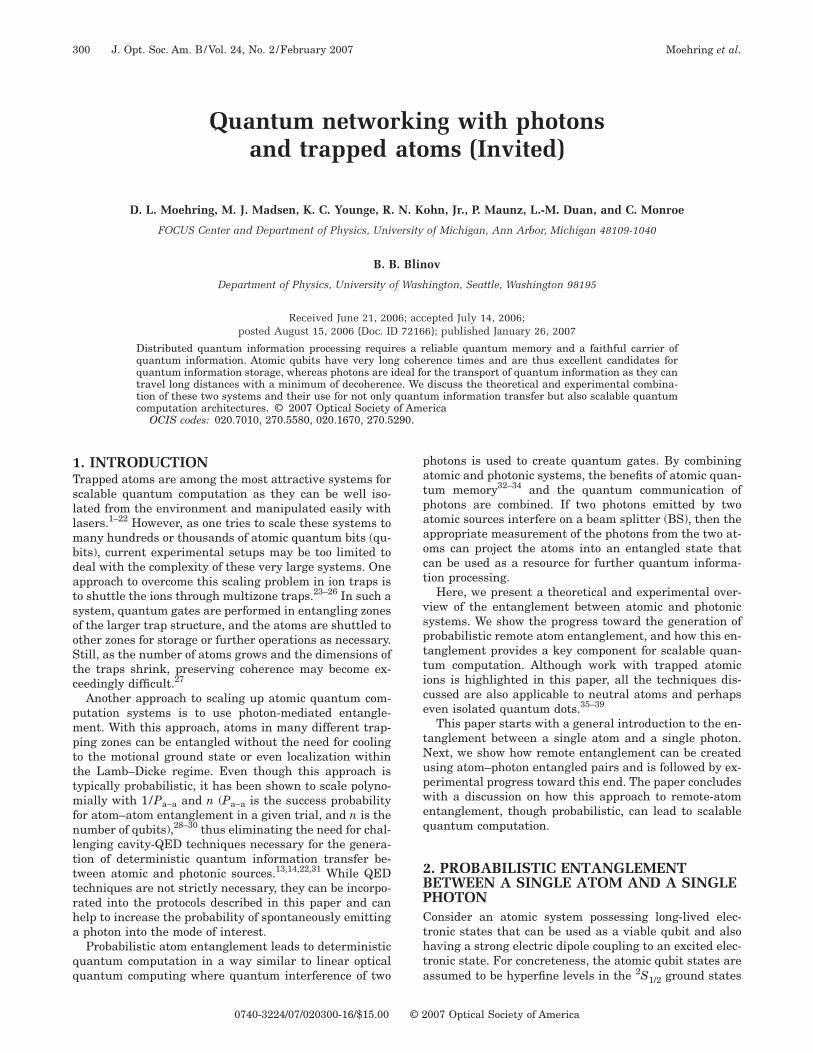
In one such protocol, proposed by Cabrillo et al.,55 twotoms are each prepared in a known ground state �↓� of ahree-level � system [Fig. 2(a)]. The two atoms are thenimultaneously weakly driven �pe=��1� to the excitedtate �e� from where the atom will decay either to theriginal state or to a second ground state �↑�. After theeak excitation pulse, the two atoms are each in the (un-ormalized) state �↓ �+���e� or for atoms a and b: ��↓ �a���e�a� � ��↓ �b+���e�b�= �↓ �a�↓ �b+���↓ �a�e�b+���e�a�↓ �b��e�a�e�b. For successful atom–atom entanglement, aingle photon must be detected from one of the two atoms,here the detector is only sensitive to the �e�→ �↑ � decay
hannel. If the atomic excitation is sufficiently small suchhat the probability of both atoms emitting a photon isegligible, �2�2�, then by the projection postulate, afteretection of the single photon, the atoms are in the en-
t�t
webpmtwpwatTtl
tDpmpc
afcena
w�±ttwmiTpApttBtt
tacp=attpieEplmflp
ttuTtfie
tptt
Fq5gop+ptsCwe�ptso
Moehring et al. Vol. 24, No. 2 /February 2007 /J. Opt. Soc. Am. B 303
angled state ��↓ �a�↑ �b+ei��↑ �a�↓ �b� /�2 where the phase=k�x comes from the optical path length difference be-
ween each atom and the detector.One limitation to the entanglement fidelity achievable
ith this protocol is the probability of multiple photonmissions. By choosing ��1, this probability is loweredut at the expense of lowering the entanglement successrobability. This protocol also requires that the atomsust be well localized such that the path length the pho-
on travels to the detector is known much better than theavelength of the emitted photon.58,59 Otherwise, thehase in the final entangled state will be unknown andill ruin entanglement. Similarly, if an atom experiencesrecoil upon emission, the evidence of which atom emit-
ed the photon will again ruin the entanglement fidelity.hese last two restrictions, however, may be overcome ifhe atoms are localized to well within the Lamb–Dickeimit.
A more robust two-photon protocol for remote-atom en-anglement, not requiring localization within the Lamb–icke limit and insensitive to the photonic phase, wasroposed independently by Duan and Kimble56 and Si-on and Irvine.57 The atomic energy levels for this ap-
roach are the same as the previous protocol, but the ex-ited state is prepared with arbitrarily high probability
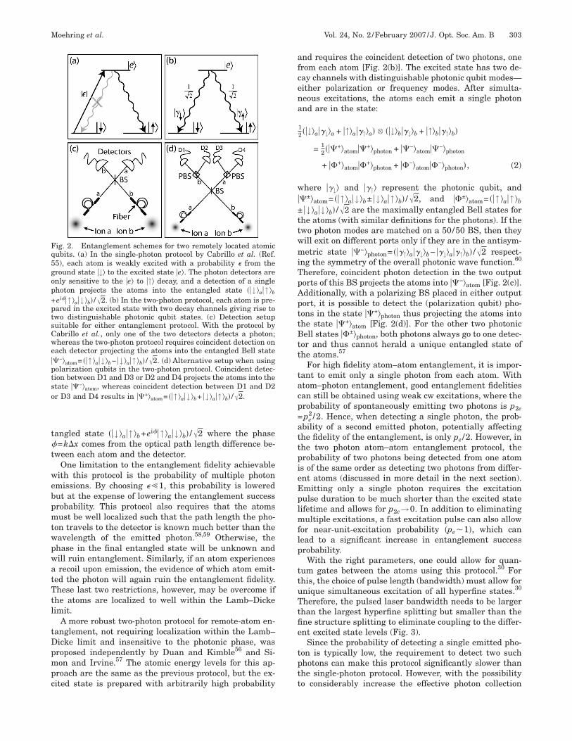
ig. 2. Entanglement schemes for two remotely located atomicubits. (a) In the single-photon protocol by Cabrillo et al. (Ref.5), each atom is weakly excited with a probability � from theround state �↓� to the excited state �e�. The photon detectors arenly sensitive to the �e� to �↑� decay, and a detection of a singlehoton projects the atoms into the entangled state ��↓ �a�↑ �b
ei��↑ �a�↓ �b� /�2. (b) In the two-photon protocol, each atom is pre-ared in the excited state with two decay channels giving rise towo distinguishable photonic qubit states. (c) Detection setupuitable for either entanglement protocol. With the protocol byabrillo et al., only one of the two detectors detects a photon;hereas the two-photon protocol requires coincident detection on
ach detector projecting the atoms into the entangled Bell state�−�atom= ��↑ �a�↓ �b− �↓ �a�↑ �b� /�2. (d) Alternative setup when usingolarization qubits in the two-photon protocol. Coincident detec-ion between D1 and D3 or D2 and D4 projects the atoms into thetate ��−�atom, whereas coincident detection between D1 and D2r D3 and D4 results in ��+�atom= ��↑ �a�↓ �b+ �↓ �a�↑ �b� /�2.
nd requires the coincident detection of two photons, onerom each atom [Fig. 2(b)]. The excited state has two de-ay channels with distinguishable photonic qubit modes—ither polarization or frequency modes. After simulta-eous excitations, the atoms each emit a single photonnd are in the state:
12 ��↓�a��↓�a + �↑�a��↑�a� � ��↓�b��↓�b + �↑�b��↑�b�
= 12 ���+�atom��+�photon + ��−�atom��−�photon
+ ��+�atom��+�photon + ��−�atom��−�photon�, �2�
here ��↓� and ��↑� represent the photonic qubit, and�±�atom= ��↑ �a�↓ �b± �↓ �a�↑ �b� /�2, and ��±�atom= ��↑ �a�↑ �b
�↓ �a�↓ �b� /�2 are the maximally entangled Bell states forhe atoms (with similar definitions for the photons). If thewo photon modes are matched on a 50/50 BS, then theyill exit on different ports only if they are in the antisym-etric state ��−�photon= ���↑�a��↓�b− ��↓�a��↑�b� /�2 respect-
ng the symmetry of the overall photonic wave function.60
herefore, coincident photon detection in the two outputorts of this BS projects the atoms into ��−�atom [Fig. 2(c)].dditionally, with a polarizing BS placed in either outputort, it is possible to detect the (polarization qubit) pho-ons in the state ��+�photon thus projecting the atoms intohe state ��+�atom [Fig. 2(d)]. For the other two photonicell states ��±�photon, both photons always go to one detec-
or and thus cannot herald a unique entangled state ofhe atoms.57
For high fidelity atom–atom entanglement, it is impor-ant to emit only a single photon from each atom. Withtom–photon entanglement, good entanglement fidelitiesan still be obtained using weak cw excitations, where therobability of spontaneously emitting two photons is p2epe
2 /2. Hence, when detecting a single photon, the prob-bility of a second emitted photon, potentially affectinghe fidelity of the entanglement, is only pe /2. However, inhe two photon atom–atom entanglement protocol, therobability of two photons being detected from one atoms of the same order as detecting two photons from differ-nt atoms (discussed in more detail in the next section).mitting only a single photon requires the excitationulse duration to be much shorter than the excited stateifetime and allows for p2e→0. In addition to eliminating
ultiple excitations, a fast excitation pulse can also allowor near-unit-excitation probability �pe1�, which canead to a significant increase in entanglement successrobability.With the right parameters, one could allow for quan-
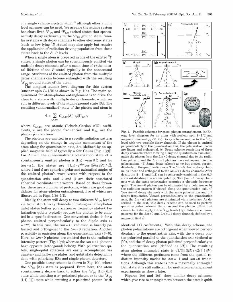
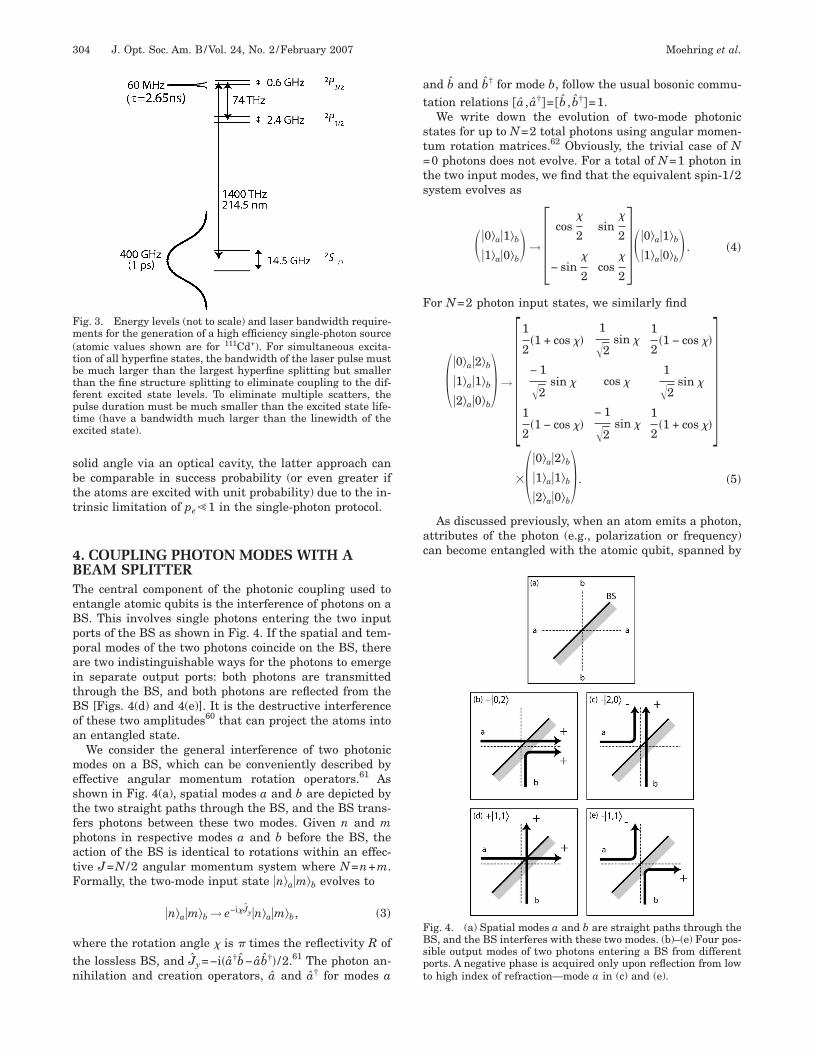
um gates between the atoms using this protocol.30 Forhis, the choice of pulse length (bandwidth) must allow fornique simultaneous excitation of all hyperfine states.30
herefore, the pulsed laser bandwidth needs to be largerhan the largest hyperfine splitting but smaller than thene structure splitting to eliminate coupling to the differ-nt excited state levels (Fig. 3).
Since the probability of detecting a single emitted pho-on is typically low, the requirement to detect two suchhotons can make this protocol significantly slower thanhe single-photon protocol. However, with the possibilityo considerably increase the effective photon collection
sbtt
4BTeBppaitBoa
mestfpatF
wtn
at
st=ts
F
ac
FBspt
Fm(tbtfpte
304 J. Opt. Soc. Am. B/Vol. 24, No. 2 /February 2007 Moehring et al.
olid angle via an optical cavity, the latter approach cane comparable in success probability (or even greater ifhe atoms are excited with unit probability) due to the in-rinsic limitation of pe�1 in the single-photon protocol.
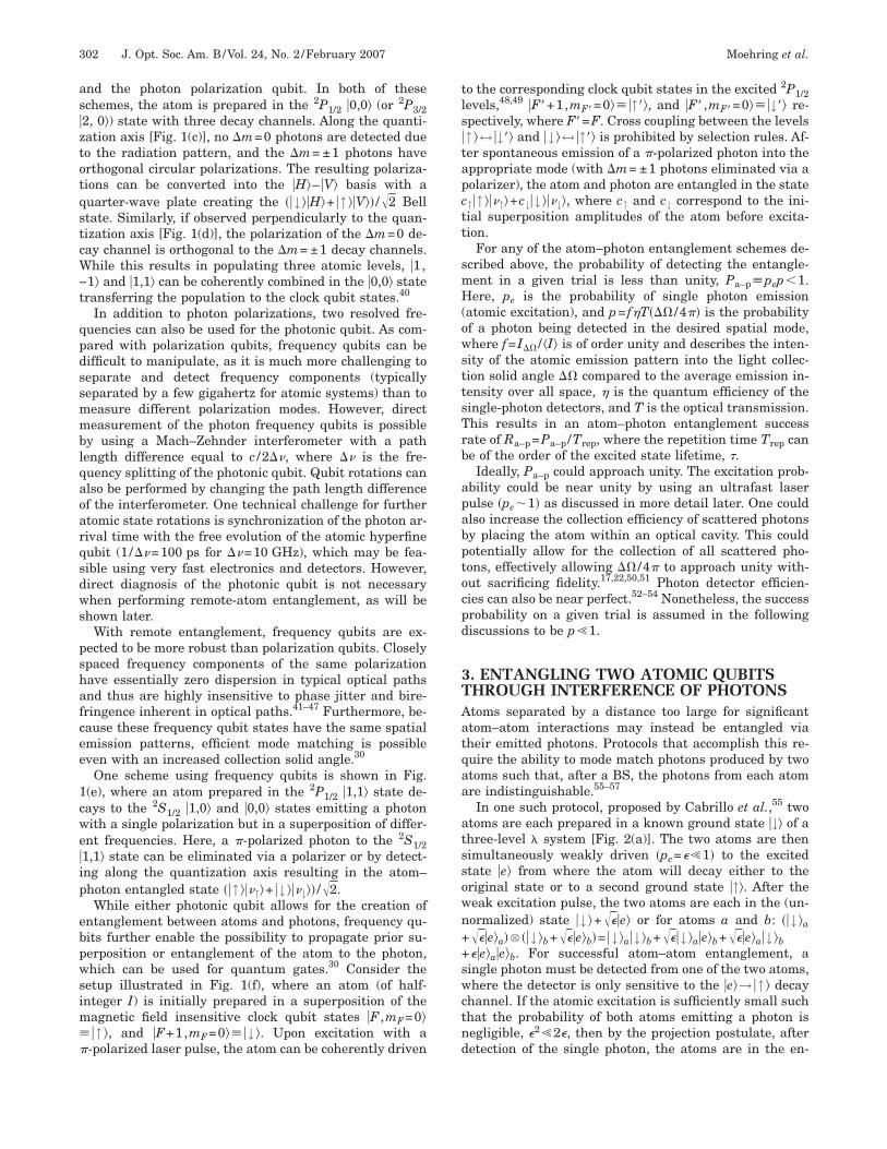
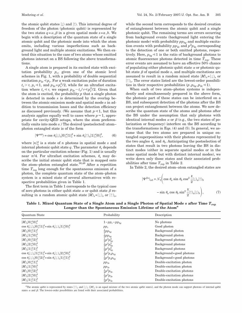
. COUPLING PHOTON MODES WITH AEAM SPLITTERhe central component of the photonic coupling used tontangle atomic qubits is the interference of photons on aS. This involves single photons entering the two inputorts of the BS as shown in Fig. 4. If the spatial and tem-oral modes of the two photons coincide on the BS, therere two indistinguishable ways for the photons to emergen separate output ports: both photons are transmittedhrough the BS, and both photons are reflected from theS [Figs. 4(d) and 4(e)]. It is the destructive interferencef these two amplitudes60 that can project the atoms inton entangled state.We consider the general interference of two photonicodes on a BS, which can be conveniently described by
ffective angular momentum rotation operators.61 Ashown in Fig. 4(a), spatial modes a and b are depicted byhe two straight paths through the BS, and the BS trans-ers photons between these two modes. Given n and mhotons in respective modes a and b before the BS, thection of the BS is identical to rotations within an effec-ive J=N /2 angular momentum system where N=n+m.ormally, the two-mode input state �n�a�m�b evolves to
�n�a�m�b → e−i�Jy�n�a�m�b, �3�
here the rotation angle � is � times the reflectivity R ofhe lossless BS, and Jy=−i�a†b− ab†� /2.61 The photon an-ihilation and creation operators, a and a† for modes a
ig. 3. Energy levels (not to scale) and laser bandwidth require-ents for the generation of a high efficiency single-photon source
atomic values shown are for 111Cd+). For simultaneous excita-ion of all hyperfine states, the bandwidth of the laser pulse muste much larger than the largest hyperfine splitting but smallerhan the fine structure splitting to eliminate coupling to the dif-erent excited state levels. To eliminate multiple scatters, theulse duration must be much smaller than the excited state life-ime (have a bandwidth much larger than the linewidth of thexcited state).
nd b and b† for mode b, follow the usual bosonic commu-ation relations a , a†�= b , b†�=1.
We write down the evolution of two-mode photonictates for up to N=2 total photons using angular momen-um rotation matrices.62 Obviously, the trivial case of N0 photons does not evolve. For a total of N=1 photon in
he two input modes, we find that the equivalent spin-1/2ystem evolves as
��0�a�1�b
�1�a�0�b → � cos
�
2sin
�
2
− sin�
2cos
�
2���0�a�1�b
�1�a�0�b . �4�
or N=2 photon input states, we similarly find
��0�a�2�b
�1�a�1�b
�2�a�0�b� → �
1
2�1 + cos ��
1
�2sin �
1
2�1 − cos ��
− 1
�2sin � cos �
1
�2sin �
1
2�1 − cos ��
− 1
�2sin �
1
2�1 + cos ��
���
�0�a�2�b
�1�a�1�b
�2�a�0�b� . �5�
As discussed previously, when an atom emits a photon,ttributes of the photon (e.g., polarization or frequency)an become entangled with the atomic qubit, spanned by
ig. 4. (a) Spatial modes a and b are straight paths through theS, and the BS interferes with these two modes. (b)–(e) Four pos-ible output modes of two photons entering a BS from differentorts. A negative phase is acquired only upon reflection from lowo high index of refraction—mode a in (c) and (e).
tftbaegtpt
tsetttitdaaptp
wionsttpss
os
wopfptttaeoba�t
dtBcstiltsttstswa
Q
�c�����cc�����
s
Moehring et al. Vol. 24, No. 2 /February 2007 /J. Opt. Soc. Am. B 305
he atomic qubit states �↓� and �↑�. This internal degree ofreedom of the photon (photonic qubit) is represented byhe two states q=� ,� in a given spatial mode s=a ,b. Weegin with a description of the quantum state of a singletomic qubit and the photonic mode into which the atommits, including various imperfections such as back-round light and multiple atomic excitations. We then ex-end this situation to the case of two atoms whose emittedhotons interact on a BS following the above transforma-ions.
A single atom is prepared in its excited state with exci-ation probability pe, given one of the atomic levelchemes in Fig. 1, with a probability of double sequentialxcitation p2e�pe. For a weak excitation pulse of duratione��, pe�1, and p2e=pe
2 /2, while for an ultrafast excita-ion where te��, we expect p2e te /��pe
2 /2. Given thathe atom is excited, the probability p that a single photons detected in mode s is determined by the overlap be-ween the atomic emission mode and spatial mode s in ad-ition to transmission losses and the detection efficiencys discussed previously. (We assume that p�1, but thisnalysis applies equally well to cases where p�1, appro-riate for cavity-QED setups, where the atom preferen-ially emits into mode s.) The desired (postselected) atom–hoton entangled state is of the form
��ent� = cos �s�↓�s�0�s��1�s
� + sin �s�↑�s�1�s��0�s
�, �6�
here �n�sq is a state of n photons in spatial mode s and
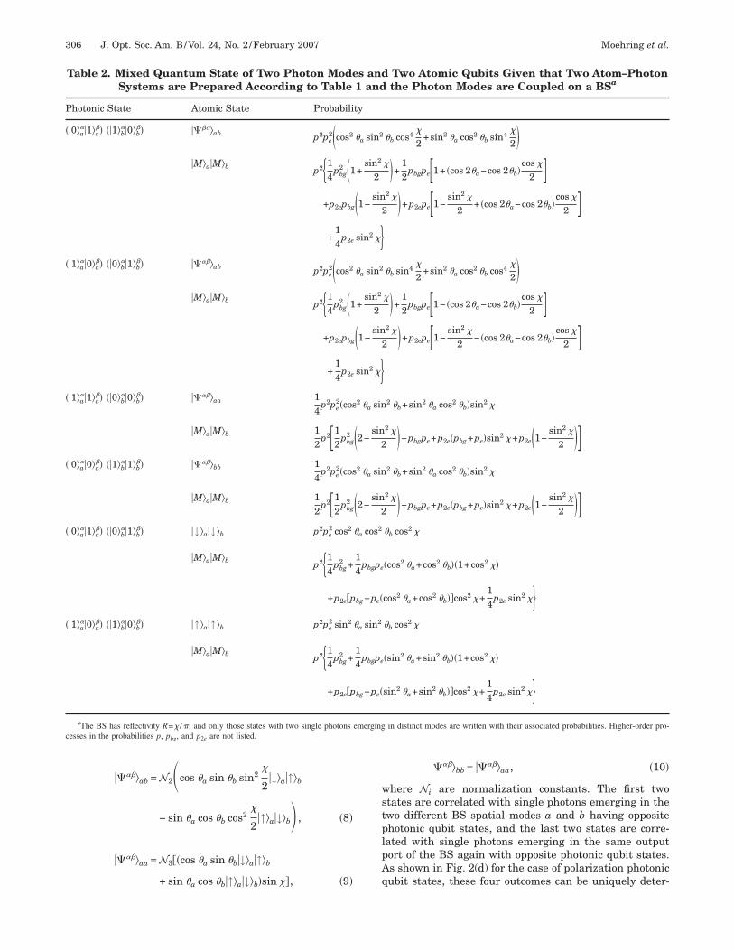
nternal photonic qubit state q. The parameter �s dependsn the particular excitation scheme (Fig. 1) and is usuallyear � /4. For ultrafast excitation schemes, �s may de-cribe the initial atomic qubit state that is mapped ontohe atom–photon entangled state.30,49 After a repetitionime Trep long enough for the spontaneous emission of ahoton, the complete quantum state of the atom–photonystem is a mixed state of several alternatives with re-pective probabilities given in Table 1.
The first term in Table 1 corresponds to the typical casef zero photons in either qubit state � or qubit state � re-ulting in a random atomic qubit state �M�s= �↓ �s or �↑ �s,
Table 1. Mixed Quantum State of a Single Atom aLonger than the Spontaneou
uantum State Probabili
M�s�0�s��0�s
� 1−ppe−pos �s�↓ �s�0�s
��1�s�+sin �s�↓ �s�1�s
��0�s� ppe
M�s�0�s��1�s
� 12ppbg
M�s�1�s��0�s
� 12ppbg
M�s�0�s��2�s
� 14p2pbg
2
M�s�2�s��0�s
� 14p2pbg
2
M�s�1�s��1�s
� 12p2pbg
2
os �s�↓ �s�1�s��1�s
�+sin �s�↓ �s�2�s��0�s
� 12p2pepbg
os �s�↓ �s�0�s��2�s
�+sin �s�↓ �s�1�s��1�s
� 12p2pepbg
M�s�0�s��1�s
� pp2e
M�s�1�s��0�s
� pp2e
M�s�0�s��2�s
� 14p2p2e
M�s�2�s��0�s
� 14p2p2e
M�s�1�s��1�s
� 12p2p2e
aThe atomic qubit is represented by states �↑ �s and �↓ �s ��M�s is an equal mixturetates � and �. The lowest-order possibilities are listed with their associated probab
hile the second term corresponds to the desired creationf entanglement between the atomic qubit and a singlehotonic qubit. The remaining terms are errors occurringrom background events (background light entering thehotonic mode) with probability ppbg and multiple excita-ion events with probability pp2e and p2p2e correspondingo the detection of one or both emitted photons, respec-ively. Here, pbg�1 is the ratio of background photons totomic fluorescence photons detected in time Trep. Theserror events are assumed to have an effective 50% chancef populating either photonic qubit state � or photonic qu-it state � of spatial mode s, and multiple excitations aressumed to result in a random mixed state �M�s= �↓ �s or↑ �s. The error states listed are the lowest-order possibili-ies in their respective probabilities �p ,pbg ,p2e�1�.
When each of two atom–photon systems is indepen-ently and simultaneously prepared in the above form,he photonic part of these states can be interfered on aS, and subsequent detection of the photons after the BSan project entanglement between the atoms. We now de-cribe the quantum state of the atoms and photons afterhe BS under the assumption that only photons withdentical internal modes � or � (e.g., the two states of po-arization or frequency) interfere on the BS according tohe transformations in Eqs. (4) and (5). In general, we as-ume that the two atoms are prepared in unique en-angled superpositions with their photons represented byhe two angles �a and �b. Anticipating the postselection oftates that result in two photons leaving the BS in dis-inct modes (either in separate spatial modes or in theame spatial mode but with distinct internal modes), werite down only those states and their associated prob-bilities after time Trep in Table 2.In Table 2, the desired atom–atom entangled states are
�����ab = N1�cos �a sin �b cos2�
2�↓�a�↑�b
− sin �a cos �b sin2�
2�↑�a�↓�b , �7�
Single Photon of Spatial Mode s after Time Trepission Lifetime of the Atoma
Description
No photonsGood photonBackground photonBackground photonBackground photonsBackground photonsBackground photonsBackground+good photonsBackground+good photonsDouble-excitation photonDouble-excitation photonDouble-excitation photonsDouble-excitation photonsDouble-excitation photons
wo atomic qubit states�, and the photon mode can support photons of internal qubit
nd as Em
ty
pbg
of the tilities.
wstplpAq
P
�
�
�
�
�
�
c
306 J. Opt. Soc. Am. B/Vol. 24, No. 2 /February 2007 Moehring et al.
�����ab = N2�cos �a sin �b sin2�
2�↓�a�↑�b
− sin �a cos �b cos2�
2�↑�a�↓�b , �8�
�����aa = N3�cos �a sin �b�↓�a�↑�b
+ sin � cos � �↑� �↓� �sin ��, �9�
Table 2. Mixed Quantum State of Two Photon ModeSystems are Prepared According to Table
hotonic State Atomic State Probabili
�0�a��1�a
�� ��1�b��0�b
�� �����ab p2pe2�cos2
�M�a�M�b p2�14
pbg2 �1
+p2epbg
�+14
p2e
�1�a��0�a
�� ��0�b��1�b
�� �����ab p2pe2�cos2
�M�a�M�b p2�14
pbg2 �1
+p2epbg
�+14
p2e
�1�a��1�a
�� ��0�b��0�b
�� �����aa 14
p2pe2�cos
�M�a�M�b 12
p212
pbg2
�0�a��0�a
�� ��1�b��1�b
�� �����bb 14
p2pe2�cos
�M�a�M�b 12
p212
pbg2
�0�a��1�a
�� ��0�b��1�b
�� �↓ �a�↓ �b p2pe2 cos2
�M�a�M�b p2�14
pbg2 +
�+p2ep
�1�a��0�a
�� ��1�b��0�b
�� �↑ �a�↑ �b p2pe2 sin2
�M�a�M�b p2�14
pbg2 +
�+p2ep
aThe BS has reflectivity R=� /�, and only those states with two single photonsesses in the probabilities p, pbg, and p2e are not listed.
a b a b
�����bb = �����aa, �10�
here Ni are normalization constants. The first twotates are correlated with single photons emerging in thewo different BS spatial modes a and b having oppositehotonic qubit states, and the last two states are corre-ated with single photons emerging in the same outputort of the BS again with opposite photonic qubit states.s shown in Fig. 2(d) for the case of polarization photonicubit states, these four outcomes can be uniquely deter-
Two Atomic Qubits Given that Two Atom–Photonthe Photon Modes are Coupled on a BSa
�b cos4�
2+sin2 �a cos2 �b sin4
�
2 �� �+
12
pbgpe1+ �cos 2�a−cos 2�b�cos �
2 ��2 � �+p2epe1−
sin2 �
2+ �cos 2�a−cos 2�b�
cos �
2 �
�b sin4�
2+sin2 �a cos2 �b cos4
�
2 �� �+
12
pbgpe1− �cos 2�a−cos 2�b�cos �
2 ��2 � �+p2epe1−
sin2 �
2− �cos 2�a−cos 2�b�
cos �
2 �
2 �b+sin2 �a cos2 �b�sin2 �
2 � �+pbgpe+p2e�pbg+pe�sin2 �+p2e�1−sin2 �
2 ��2 �b+sin2 �a cos2 �b�sin2 �
2 � �+pbgpe+p2e�pbg+pe�sin2 �+p2e�1−sin2 �
2 ���b cos2 �
�cos2 �a+cos2 �b��1+cos2 ���cos2 �a+cos2 �b��cos2 �+
14
p2e sin2 ���b cos2 �
�sin2 �a+sin2 �b��1+cos2 ���sin2 �a+sin2 �b��cos2 �+
14
p2e sin2 ��in distinct modes are written with their associated probabilities. Higher-order pro-
s and1 and
ty
�a sin2
+sin2
2
�1−sin
2
sin2 ���a sin2
+sin2
2
�1−sin
2
sin2 ��2 �a sin
�2−sin
2
2 �a sin
�2−sin
2
�a cos2
14
pbgpe
bg+pe�
�a sin2
14
pbgpe
bg+pe�
emerging
mpt
o
w“emttgos=
itopeTdt
cctm
wa
Trplhf�dt
Ott+pvwar
5PWmddlpadt
tFslF
2cl�
pitPbdotrsnism(srp
Moehring et al. Vol. 24, No. 2 /February 2007 /J. Opt. Soc. Am. B 307
ined by separating the photonic qubit states at the out-ut of each BS output port and triggering on the relevantwo-photon coincidence event.
For a 50/50 BS ��=� /2�, the above states simplify tone of the following entangled states:
��ent�diff = N�cos �a sin �b�↓�a�↑�b − sin �a cos �b�↑�a�↓�b�,
�11�
��ent�same = N�cos �a sin �b�↓�a�↑�b + sin �a cos �b�↑�a�↓�b�,
�12�
here N is a normalization constant, and the subscriptsdiff” and “same” refer to cases where the two photonsmerged in different spatial modes or the same spatialode but separate photonic qubit states. This postselec-
ion process can amount to a measurement gate betweenhe two atoms originally prepared in arbitrary statesiven by �a and �b.30 For �a=�b (identically prepared at-ms), the above states simplify to the odd-parity Belltates ��−�atom= ��↓ �a�↑ �b− �↑ �a�↓ �b� /�2 and ��+�atom
��↓ �a�↑ �b+ �↑ �a�↓ �b� /�2, respectively.When the BS is not exactly 50/50 ���� /2�, the result-
ng errors can limit the fidelity of the gate or the en-angled state. By detecting all possibilities of photonicutput states, a biased BS can be diagnosed by the ap-earance of events with identical photonic qubit statesmerging in distinct BS output ports (last two rows ofable 2) assuming that errors from background counts orouble-excitation events are rare. In the following, weherefore assume that the BS is unbiased ��=� /2�.
Including noise from background counts and double ex-itations, we find that when two photons are detected inoincidence in the desired output ports of the BS (for ei-her the ��ent�diff or the ��ent�same state), the postselectedixed state of the two atoms alone becomes
�post = Pgood��ent���ent� + Pbad�MaMb��MaMb�, �13�
here the probabilities of a desired entangled state Pgoodnd the noisy mixed state Pbad are given by
Pgood =1
4p2pe
2�cos2 �a sin2 �b + sin2 �a cos2 �b�, �14�
Pbad =p2
2 �pbg�3
4pbg + pe + p2e�pbg + pe +
1
2 � .
�15�
he above probabilities do not add to one because they areelative to the (most probable) null case of not detectinghotons in each of the output modes of the BS. Neverthe-ess, we can calculate a lower limit on the fidelity of theeralded entangled atomic qubit state most importantlyor the maximally entangled Bell states ��−�atom and�+�atom ��a=�b=� /4�. Noting that the fidelity of the ran-om mixed state �MaMb� is 1/4, we find that the fidelity ofhe postselected state is
F =Pgood + 1
4Pbad
Pgood + Pbad
=pe
2 + pbg� 34pbg + pe� + p2e�pbg + pe + 1
2��pe
2 + 4pbg� 34pbg + pe� + p2e�pbg + pe + 1
2��. �16�
ne criterion for the generation of entanglement is thathe fidelity be greater than 1/2, which leads to the condi-ion that Pgood�Pbad/2, or pe
2�2pbg� 34pbg+pe�+2p2e�pbg
pe+ 12 �. It is clear that when using a weak excitation
ulse of duration te��, the entanglement fidelity is se-erely limited �Pbad�Pgood�, since p2e=pe
2 /2. However,hen using ultrafast excitation pulses such that pe→1nd p2e→0, only the background photons can affect theesulting fidelity: F1−3pbg.
. EXPERIMENTS WITH PHOTONOLARIZATION QUBITShile matter–light entanglement has been implicit inany experimental systems over the past few
ecades,58,63–77 the first system with sufficient control forirect measurement of entanglement between matter andight was the trapped ion system.73,74 In this system, ahoton is spontaneously emitted from a single trappedtomic ion, which is initially excited to a state with twoecay channels, resulting in photons of different polariza-ions [Fig. 1(b)].
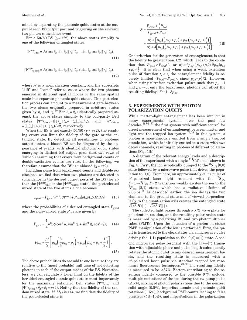
A diagram of the relevant energy levels and a descrip-ion of the experiment with a single 111Cd+ ion is shown inig. 5. First, the ion is optically pumped to the 2S1/2 �0,0�tate followed by a microwave pulse that drives the popu-ation to �1,0�. From here, an approximately 50 ns pulse of+-polarized laser light resonant with the 2S1/2=1↔ 2P3/2 F=2 transition weakly excites the ion to the
2P3/2 �2,1� state, which has a radiative lifetime of.65 ns.78 As described earlier, the ion decays via twohannels to the ground state and if viewed perpendicu-arly to the quantization axis creates the entangled state1/3�H��↓ �+�2/3�V��↑ �.The collected light passes through a � /2 wave plate for
olarization rotation, and the resulting polarization states measured by a polarizing BS and two photomultiplierubes (PMTs). Upon the detection of a photon on eitherMT, manipulation of the ion is performed. First, the qu-it is transferred to the clock states via a microwave pulseriving the �1,1� population to the �0,0���↑� state. A sec-nd microwave pulse resonant with the �↓ �↔ �↑� transi-ion with adjustable phase and pulse length subsequentlyotates the atomic qubit to any desired measurement ba-is, and the resulting state is measured with a+-polarized laser pulse via standard trapped ion reso-ance fluorescence techniques.79,80 The resulting fidelity
s measured to be �87%. Factors contributing to the re-ulting fidelity compared to the possible 97% include:ultiple excitations of the ion during the cw pump pulse
2.5%), mixing of photon polarizations due to the nonzeroolid angle (0.5%), imperfect atomic and photonic qubitotations (1.5%), background PMT counts leading to falseositives (5%–10%), and imperfections in the polarization
obmbs
ppsr�rgsli
6FImbge
pt
e
s
FwiasndSRrwfuecb[ps
Fwia2
pptpfwbt
308 J. Opt. Soc. Am. B/Vol. 24, No. 2 /February 2007 Moehring et al.
ptics (3%). Since the qubit is transferred to the clock qu-it states right after photon emission, we estimate thatagnetic field fluctuations affect the atomic qubit fidelity
y �1%. When combined, these sources of error are con-istent with the observed fidelity.
As mentioned above, this entanglement generation is arobabilistic process. With the cw excitation scheme, therobability of emitting a single photon in each trial is re-tricted to pe�0.1 to suppress multiple excitations. Theesulting success probability is Pa–p=pe�T�� /4��= �0.1��0.2��0.4��0.02��1.6�10−4. The experiment repetition
ate is R=1/Trep=104 s−1 resulting in an entanglementeneration rate Ra–p=Pa–pR�1.6 s−1, but improvementsuch as higher excitation probability using an ultrafastaser pulse and an increased repetition rate significantlyncrease this yield.
. EXPERIMENTS WITH PHOTONREQUENCY QUBITS
n a recent experiment, indirect evidence of the entangle-ent between an atomic qubit and a photon frequency qu-
it was demonstrated in the cadmium ion system.49 A dia-ram of the relevant energy levels and a description of thexperiment are given in Fig. 6. First, the ion is optically
ig. 5. Experimental procedure for atom–photon entanglementith photon polarization qubits (Refs. 73 and 74). (a) The atom is
nitialized to the �1,0� state via optical pumping to the �0,0� statend a microwave transfer pulse. (b) The atom is driven to theP3/2 �2,1� excited state resulting in spontaneous emission via twohoton decay channels of orthogonal polarizations when viewederpendicularly to the quantization axis. The resulting en-angled state is �1/3�H��↓ �+�2/3�V��↑ �. (c) Microwave �wave�ulse resonant with the �1,1�↔ �0,0� transition coherently trans-ers the population to the clock qubit states. (d) Second micro-ave pulse prepares the atomic qubit for measurement in anyasis. (e) +-polarized laser pulse performs the state detection ofhe atomic qubit using resonance fluorescence techniques.
umped to �0,0���↑ �, and a microwave pulse prepareshe ion in the state ��↓ �+ �↑ �� /�2 [Fig. 6(a)].
Next, a single �-polarized ultrafast laser pulse coher-ntly drives the superposition to the clock states in the
2P3/2 manifold with near-unit probability—similar to thecheme described in Section 2 [Fig. 1(f)]. The coherence
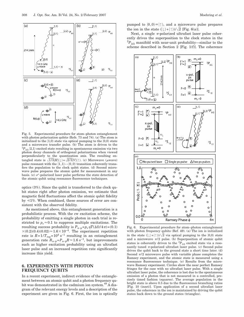
ig. 6. Experimental procedure for atom–photon entanglementith photon frequency qubits (Ref. 49). (a) The ion is initialized
n the state ��↓ �+ �↑ �� /�2 via optical pumping to the �0,0� statend a microwave � /2 pulse. (b) Superposition of atomic qubittates is coherently driven to the 2P3/2 excited state via a reso-antly tuned �-polarized ultrafast laser pulse. (c) Second pulserives the qubit back to the ground state a short time later. (d)econd � /2 microwave pulse with variable phase completes theamsey experiment, and the atomic state is measured using a
esonance fluorescence technique. (e) Results from the micro-ave Ramsey experiment. Circles show the near perfect Ramsey
ringes for the case with no ultrafast laser pulse. With a singleltrafast laser pulse, the coherence is lost due to the spontaneousmission of a photon that is not measured in a controlled, pre-isely timed fashion (squares). The average population in theright state is above 0.5 due to the fluorescence branching ratiosFig. 10 (inset)]. Upon application of a second ultrafast laserulse, the coherence in the ion is maintained by driving the qubittates back down to the ground states (triangles).
iwslaso(tttit
dcg6tpie−csat
7EAOtiPdatbwtpbBrp
atteglcst0
tltd
tasit
fstSdra
BpTtcc
Fc=vptacw
Fmmpa
Moehring et al. Vol. 24, No. 2 /February 2007 /J. Opt. Soc. Am. B 309
n this excitation scheme is demonstrated using a micro-ave Ramsey experiment. In the absence of ultrafast la-
er pulses, the Ramsey contrast is essentially perfect. Fol-owing the application of the ultrafast laser pulse, thetom is driven to the excited state. The excited atom thenpontaneously decays, and without precise measurementf the photon polarization, frequency, and emission timewith respect to the 14 GHz frequency qubit separation)he coherence is lost, as seen in Fig. 6(e). The uncon-rolled measurement of the photon results in tracing overhe photon portion of the density matrix, and the result-ng loss in contrast is consistent with prior ion–photon en-anglement.
To show that the excitation pulse is indeed coherentlyriving the superposition to the excited state, the Ramseyoherence is recovered by driving the ion back down to theround state before spontaneous emission occurs [Fig.(c)]. With a pair of picosecond laser pulses incident onhe ion between the microwave pulses, the contrast reap-ears with a phase shift proportional to the time �t spentn the excited state and the hyperfine frequency differ-nce between the ground and excited state levels: �t��0�1�= �680 ps��13.9 GHz�=18.9� [Fig. 6(e)]. The observedontrast is only 40% of the contrast without ultrafast la-er pulses due to limited laser power in the second pulsend spontaneous decay �23% � during the delay time be-ween the ultrafast pulses.
. REMOTE ATOM ENTANGLEMENTXPERIMENTAL PROGRESS. Two-Photon Interferencence two atoms are entangled with their respective pho-
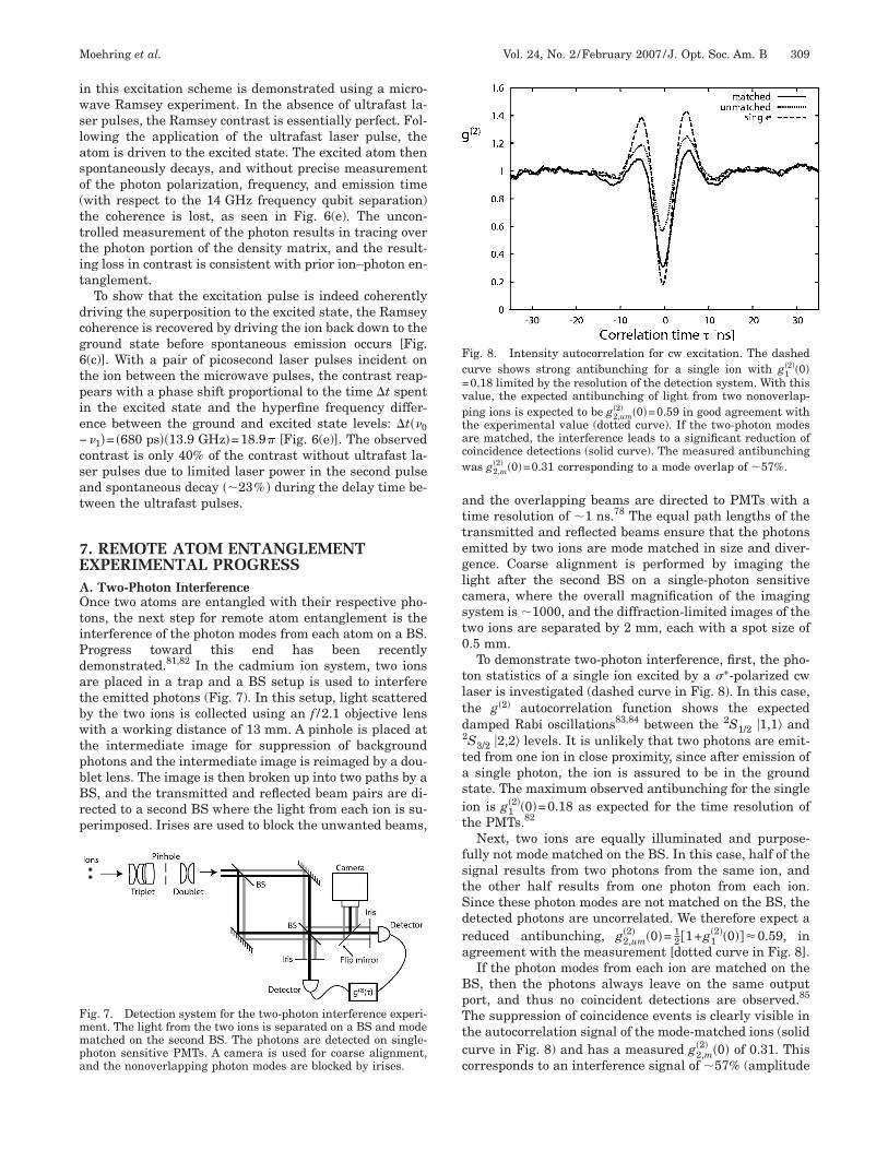
ons, the next step for remote atom entanglement is thenterference of the photon modes from each atom on a BS.rogress toward this end has been recentlyemonstrated.81,82 In the cadmium ion system, two ionsre placed in a trap and a BS setup is used to interferehe emitted photons (Fig. 7). In this setup, light scatteredy the two ions is collected using an f /2.1 objective lensith a working distance of 13 mm. A pinhole is placed at
he intermediate image for suppression of backgroundhotons and the intermediate image is reimaged by a dou-let lens. The image is then broken up into two paths by aS, and the transmitted and reflected beam pairs are di-ected to a second BS where the light from each ion is su-erimposed. Irises are used to block the unwanted beams,
ig. 7. Detection system for the two-photon interference experi-ent. The light from the two ions is separated on a BS and modeatched on the second BS. The photons are detected on single-
hoton sensitive PMTs. A camera is used for coarse alignment,nd the nonoverlapping photon modes are blocked by irises.
nd the overlapping beams are directed to PMTs with aime resolution of 1 ns.78 The equal path lengths of theransmitted and reflected beams ensure that the photonsmitted by two ions are mode matched in size and diver-ence. Coarse alignment is performed by imaging theight after the second BS on a single-photon sensitiveamera, where the overall magnification of the imagingystem is 1000, and the diffraction-limited images of thewo ions are separated by 2 mm, each with a spot size of.5 mm.To demonstrate two-photon interference, first, the pho-
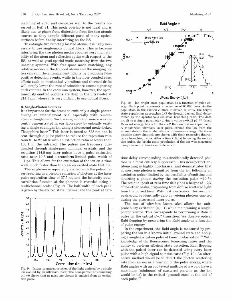
on statistics of a single ion excited by a +-polarized cwaser is investigated (dashed curve in Fig. 8). In this case,he g�2� autocorrelation function shows the expectedamped Rabi oscillations83,84 between the 2S1/2 �1,1� and
2S3/2 �2,2� levels. It is unlikely that two photons are emit-ed from one ion in close proximity, since after emission of
single photon, the ion is assured to be in the groundtate. The maximum observed antibunching for the singleon is g1
�2��0�=0.18 as expected for the time resolution ofhe PMTs.82
Next, two ions are equally illuminated and purpose-ully not mode matched on the BS. In this case, half of theignal results from two photons from the same ion, andhe other half results from one photon from each ion.ince these photon modes are not matched on the BS, theetected photons are uncorrelated. We therefore expect aeduced antibunching, g2,um
�2� �0�= 12 1+g1
�2��0���0.59, ingreement with the measurement [dotted curve in Fig. 8].If the photon modes from each ion are matched on the
S, then the photons always leave on the same outputort, and thus no coincident detections are observed.85
he suppression of coincidence events is clearly visible inhe autocorrelation signal of the mode-matched ions (solidurve in Fig. 8) and has a measured g2,m
�2� �0� of 0.31. Thisorresponds to an interference signal of 57% (amplitude
ig. 8. Intensity autocorrelation for cw excitation. The dashedurve shows strong antibunching for a single ion with g1
�2��0�0.18 limited by the resolution of the detection system. With thisalue, the expected antibunching of light from two nonoverlap-ing ions is expected to be g2,um
�2� �0�=0.59 in good agreement withhe experimental value (dotted curve). If the two-photon modesre matched, the interference leads to a significant reduction ofoincidence detections (solid curve). The measured antibunchingas g2,m
�2� �0�=0.31 corresponding to a mode overlap of 57%.
mslss
eibBirtpewdt2
BIdaciTsf1drrs
spcmi
tttaedTofpd
pppRo
pikawpnrRmwe
FepsmaRAgpctu
Fiat
310 J. Opt. Soc. Am. B/Vol. 24, No. 2 /February 2007 Moehring et al.
atching of 75%) and compares well to the results ob-erved in Ref. 81. This mode overlap is not ideal and isikely due to phase front distortions from the two atomicources as they sample different parts of many opticalurfaces before finally interfering on the BS.
To entangle two remotely located atoms, it is likely nec-ssary to use single-mode optical fibers. This is becausenterfering the two photon modes requires very high sta-ility of the atom and collection optics with respect to theS, as well as good spatial mode matching from the two
maging systems. With free-space mode matching, anyelative motion of the trapped atoms and the imaging op-ics can ruin the entanglement fidelity by producing falseositive detection events, while in the fiber coupled case,ffects such as mechanical vibrations and thermal driftsill simply lower the rate of coincidence counts (ignoringark counts). In the cadmium system, however, the spon-aneously emitted photons are deep in the ultraviolet at14.5 nm, where it is very difficult to use optical fibers.
. Single-Photon Sourcest is important for the atoms to emit only a single photonuring an entanglement trial especially with remote-tom entanglement. Such a single-photon source was re-ently demonstrated in our laboratory by optically excit-ng a single cadmium ion using a picosecond mode-lockedi:sapphire laser.82 This laser is tuned to 858 nm and isent through a pulse picker to reduce the repetition raterom 81 to 27 MHz with an extinction ratio of better than00:1 in the infrared. The pulses are frequency qua-rupled through single-pass nonlinear crystals, and theesulting 214.5 nm laser pulses have a pulse extinctionatio near 10−8 and a transform-limited pulse width of1 ps. This allows for the excitation of the ion on a time
cale much faster than the 2.65 ns excited state lifetime.The single ion is repeatedly excited with the pulsed la-
er resulting in a periodic emission of photons at the laserulse separation time of 37.5 ns, and the intensity auto-orrelation function of the photons is recorded using aultichannel scaler (Fig. 9). The half-width of each peak
s given by the excited state lifetime, and the peak at zero
ig. 9. Intensity autocorrelation of the light emitted by a singleon excited by an ultrafast laser. The near-perfect antibunchingt t=0 shows that at most one photon is emitted from an excita-ion pulse.
ime delay corresponding to coincidentally detected pho-ons is almost entirely suppressed. This near-perfect an-ibunching is highly nonclassical and demonstrates thatt most one photon is emitted from the ion following anxcitation pulse (limited by the possibility of emitting andetecting a photon during the excitation pulse �10−6).he residual peak at zero time delay has a height of 2%f the other peaks, originating from diffuse scattered lightrom the pulsed laser. With fast electronics, this residualeak could be identically zero by vetoing photons emitteduring the picosecond laser pulse.The use of ultrafast lasers also allows for unit-
robability excitation �pe1� while maintaining a single-hoton source. This corresponds to performing a Rabi �ulse on the optical S–P transition. We observe opticalabi flopping by measuring the Rabi angle as a functionf pulse energy.
In the experiment, the Rabi angle is measured by pre-aring the ion in a known initial ground state and apply-ng a single excitation pulse of known polarization.49 Withnowledge of the fluorescence branching ratios and thebility to perform efficient state detection, Rabi floppingith the pulsed laser can be detected using every laserulse with a high signal-to-noise ratio (Fig. 10). An alter-ative method would be to detect the photon scatteringate from an ion as a function of the pulse energy, whereabi angles with an odd (even) multiple of � would have aaximum (minimum) of scattered photons as the ionould be left in the excited (ground) state at the end ofach pulse.86
ig. 10. Ion bright state population as a function of pulse en-rgy. Each point represents a collection of 60,000 runs. As theopulation in the excited P state is driven to unity, the brighttate population approaches 1/3 (horizontal dashed line) deter-ined by the spontaneous emission branching ratio. The data
re fit to a single parameter giving a value a=0.42 pJ−1/2. Inset:elevant energy levels for the S–P Rabi oscillation experiment.
�-polarized ultrafast laser pulse excited the ion from theround state to the excited state with variable energy. The threeossible decay channels are shown with their respective fluores-ence branching ratios. After a time �10 s� following the excita-ion pulse, the bright state population of the ion was measuredsing resonance fluorescence detection.
gp�cgtsdwiiapseeua
8NARAqtrakitie
q oEadatg
ota1qttcttbatsluco
Fooett
FoTplpte
Moehring et al. Vol. 24, No. 2 /February 2007 /J. Opt. Soc. Am. B 311
In the experiment, the ion is prepared in the �0,0�round state through optical pumping.87 A single linearlyolarized picosecond laser pulse excites the ion on the P3/2
1,0� state. After a time �10 s�, much longer than the ex-ited state lifetime, the ion has decayed back to the S1/2round-state levels via spontaneous emission followinghe fluorescence branching ratios. The atomic groundtates are then measured using resonance fluorescenceetection, where all three F=1 states are equally bright,hile the F=0 state is dark79,80,88 with the results shown
n Fig. 10. The available power from the pulsed laser lim-ts the Rabi rotation angle to roughly �, and the datagree well with the estimates based on the beam waist,ulse length, and pulse shape.49 The probability of mea-uring the bright state is equal to 1/3 the probability ofxcitation to the excited state as follows from the CG co-fficients [Fig. 10 (inset)]. Hence, we have shown thatnit excitation and single-photon emission can bechieved with ultrafast laser pulses.
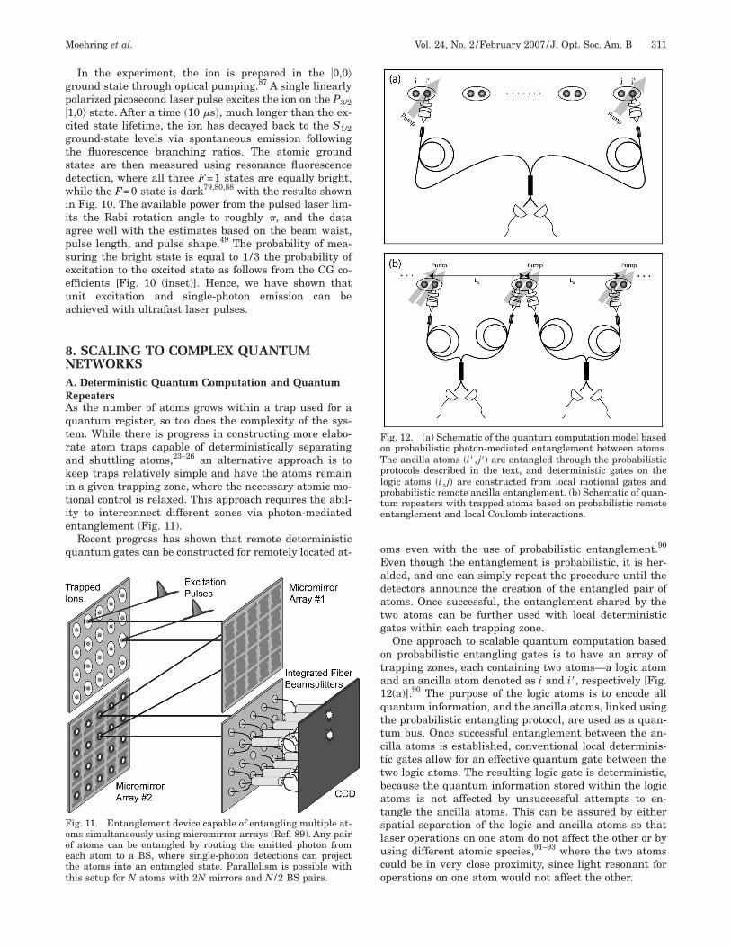
. SCALING TO COMPLEX QUANTUMETWORKS. Deterministic Quantum Computation and Quantumepeaterss the number of atoms grows within a trap used for auantum register, so too does the complexity of the sys-em. While there is progress in constructing more elabo-ate atom traps capable of deterministically separatingnd shuttling atoms,23–26 an alternative approach is toeep traps relatively simple and have the atoms remainn a given trapping zone, where the necessary atomic mo-ional control is relaxed. This approach requires the abil-ty to interconnect different zones via photon-mediatedntanglement (Fig. 11).
Recent progress has shown that remote deterministicuantum gates can be constructed for remotely located at-
ig. 11. Entanglement device capable of entangling multiple at-ms simultaneously using micromirror arrays (Ref. 89). Any pairf atoms can be entangled by routing the emitted photon fromach atom to a BS, where single-photon detections can projecthe atoms into an entangled state. Parallelism is possible withhis setup for N atoms with 2N mirrors and N /2 BS pairs.
ms even with the use of probabilistic entanglement.90
ven though the entanglement is probabilistic, it is her-lded, and one can simply repeat the procedure until theetectors announce the creation of the entangled pair oftoms. Once successful, the entanglement shared by thewo atoms can be further used with local deterministicates within each trapping zone.
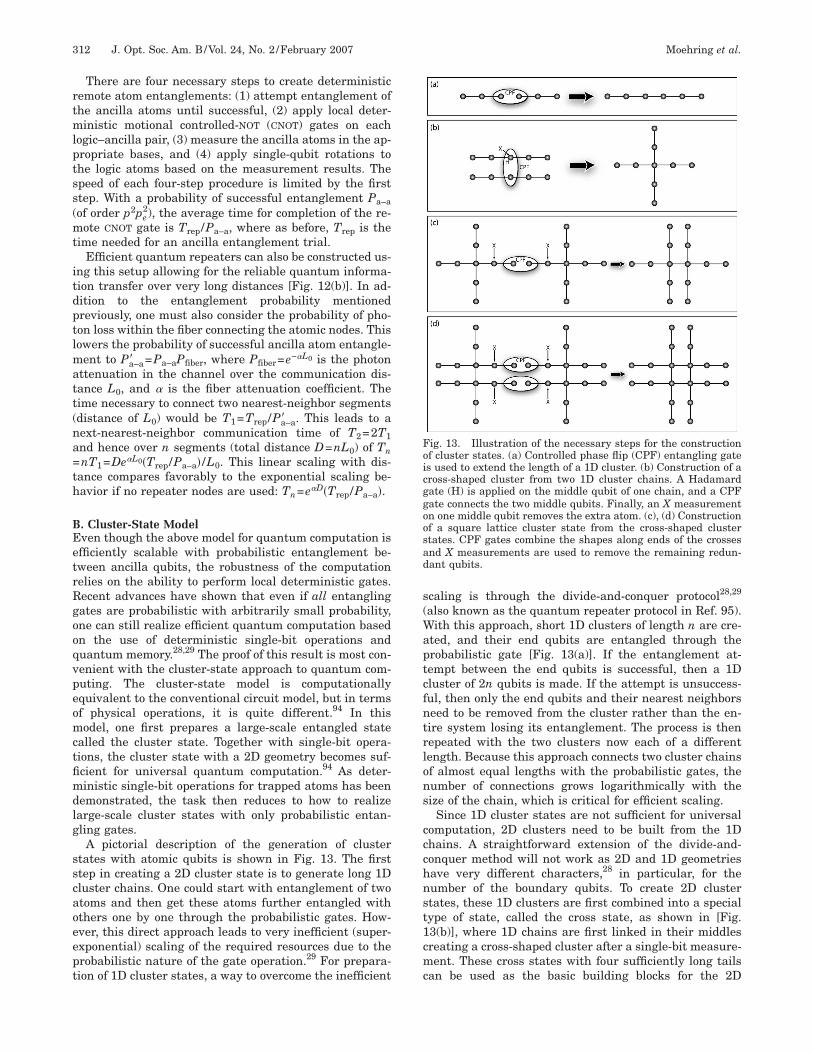
One approach to scalable quantum computation basedn probabilistic entangling gates is to have an array ofrapping zones, each containing two atoms—a logic atomnd an ancilla atom denoted as i and i�, respectively [Fig.2(a)].90 The purpose of the logic atoms is to encode alluantum information, and the ancilla atoms, linked usinghe probabilistic entangling protocol, are used as a quan-um bus. Once successful entanglement between the an-illa atoms is established, conventional local determinis-ic gates allow for an effective quantum gate between thewo logic atoms. The resulting logic gate is deterministic,ecause the quantum information stored within the logictoms is not affected by unsuccessful attempts to en-angle the ancilla atoms. This can be assured by eitherpatial separation of the logic and ancilla atoms so thataser operations on one atom do not affect the other or bysing different atomic species,91–93 where the two atomsould be in very close proximity, since light resonant forperations on one atom would not affect the other.
ig. 12. (a) Schematic of the quantum computation model basedn probabilistic photon-mediated entanglement between atoms.he ancilla atoms �i� , j�� are entangled through the probabilisticrotocols described in the text, and deterministic gates on theogic atoms �i , j� are constructed from local motional gates androbabilistic remote ancilla entanglement. (b) Schematic of quan-um repeaters with trapped atoms based on probabilistic remotentanglement and local Coulomb interactions.
rtmlptss(mt
itdptlmatt(na=th
BEetrRgooqvpeomctfimdlg
sscaoeept
s(Waptcfntrlons
ccchnst1cmc
Foicggoosad
312 J. Opt. Soc. Am. B/Vol. 24, No. 2 /February 2007 Moehring et al.
There are four necessary steps to create deterministicemote atom entanglements: (1) attempt entanglement ofhe ancilla atoms until successful, (2) apply local deter-inistic motional controlled-NOT (CNOT) gates on each
ogic–ancilla pair, (3) measure the ancilla atoms in the ap-ropriate bases, and (4) apply single-qubit rotations tohe logic atoms based on the measurement results. Thepeed of each four-step procedure is limited by the firsttep. With a probability of successful entanglement Pa–aof order p2pe
2), the average time for completion of the re-ote CNOT gate is Trep/Pa–a, where as before, Trep is the
ime needed for an ancilla entanglement trial.Efficient quantum repeaters can also be constructed us-
ng this setup allowing for the reliable quantum informa-ion transfer over very long distances [Fig. 12(b)]. In ad-ition to the entanglement probability mentionedreviously, one must also consider the probability of pho-on loss within the fiber connecting the atomic nodes. Thisowers the probability of successful ancilla atom entangle-
ent to Pa–a� =Pa–aPfiber, where Pfiber=e−�L0 is the photonttenuation in the channel over the communication dis-ance L0, and � is the fiber attenuation coefficient. Theime necessary to connect two nearest-neighbor segmentsdistance of L0) would be T1=Trep/Pa–a� . This leads to aext-nearest-neighbor communication time of T2=2T1nd hence over n segments (total distance D=nL0) of TnnT1=De�L0�Trep/Pa–a� /L0. This linear scaling with dis-
ance compares favorably to the exponential scaling be-avior if no repeater nodes are used: Tn=e�D�Trep/Pa–a�.
. Cluster-State Modelven though the above model for quantum computation isfficiently scalable with probabilistic entanglement be-ween ancilla qubits, the robustness of the computationelies on the ability to perform local deterministic gates.ecent advances have shown that even if all entanglingates are probabilistic with arbitrarily small probability,ne can still realize efficient quantum computation basedn the use of deterministic single-bit operations anduantum memory.28,29 The proof of this result is most con-enient with the cluster-state approach to quantum com-uting. The cluster-state model is computationallyquivalent to the conventional circuit model, but in termsf physical operations, it is quite different.94 In thisodel, one first prepares a large-scale entangled state
alled the cluster state. Together with single-bit opera-ions, the cluster state with a 2D geometry becomes suf-cient for universal quantum computation.94 As deter-inistic single-bit operations for trapped atoms has been
emonstrated, the task then reduces to how to realizearge-scale cluster states with only probabilistic entan-ling gates.
A pictorial description of the generation of clustertates with atomic qubits is shown in Fig. 13. The firsttep in creating a 2D cluster state is to generate long 1Dluster chains. One could start with entanglement of twotoms and then get these atoms further entangled withthers one by one through the probabilistic gates. How-ver, this direct approach leads to very inefficient (super-xponential) scaling of the required resources due to therobabilistic nature of the gate operation.29 For prepara-ion of 1D cluster states, a way to overcome the inefficient
caling is through the divide-and-conquer protocol28,29
also known as the quantum repeater protocol in Ref. 95).ith this approach, short 1D clusters of length n are cre-
ted, and their end qubits are entangled through therobabilistic gate [Fig. 13(a)]. If the entanglement at-empt between the end qubits is successful, then a 1Dluster of 2n qubits is made. If the attempt is unsuccess-ul, then only the end qubits and their nearest neighborseed to be removed from the cluster rather than the en-ire system losing its entanglement. The process is thenepeated with the two clusters now each of a differentength. Because this approach connects two cluster chainsf almost equal lengths with the probabilistic gates, theumber of connections grows logarithmically with theize of the chain, which is critical for efficient scaling.
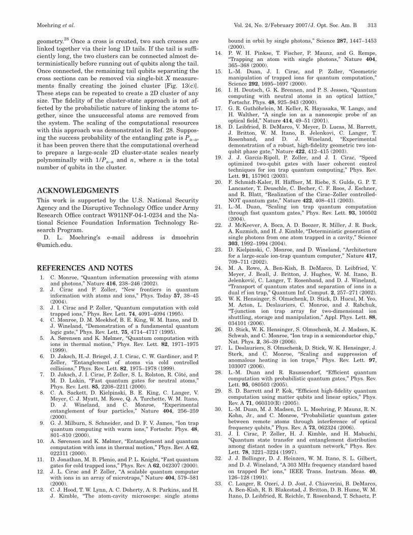
Since 1D cluster states are not sufficient for universalomputation, 2D clusters need to be built from the 1Dhains. A straightforward extension of the divide-and-onquer method will not work as 2D and 1D geometriesave very different characters,28 in particular, for theumber of the boundary qubits. To create 2D clustertates, these 1D clusters are first combined into a specialype of state, called the cross state, as shown in [Fig.3(b)], where 1D chains are first linked in their middlesreating a cross-shaped cluster after a single-bit measure-ent. These cross states with four sufficiently long tails
an be used as the basic building blocks for the 2D
ig. 13. Illustration of the necessary steps for the constructionf cluster states. (a) Controlled phase flip (CPF) entangling gates used to extend the length of a 1D cluster. (b) Construction of aross-shaped cluster from two 1D cluster chains. A Hadamardate (H) is applied on the middle qubit of one chain, and a CPFate connects the two middle qubits. Finally, an X measurementn one middle qubit removes the extra atom. (c), (d) Constructionf a square lattice cluster state from the cross-shaped clustertates. CPF gates combine the shapes along ends of the crossesnd X measurements are used to remove the remaining redun-ant qubits.
glctOcmTsfgtwiitpn
ATARts
@
R
1
1
1
1
1
1
1
1
1
1
2
2
2
2
2
2
2
2
2
2
3
3
3
3
Moehring et al. Vol. 24, No. 2 /February 2007 /J. Opt. Soc. Am. B 313
eometry.28 Once a cross is created, two such crosses areinked together via their long 1D tails. If the tail is suffi-iently long, the two clusters can be connected almost de-erministically before running out of qubits along the tail.nce connected, the remaining tail qubits separating the
ross sections can be removed via single-bit X measure-ents finally creating the joined cluster [Fig. 13(c)].hese steps can be repeated to create a 2D cluster of anyize. The fidelity of the cluster-state approach is not af-ected by the probabilistic nature of linking the atoms to-ether, since the unsuccessful atoms are removed fromhe system. The scaling of the computational resourcesith this approach was demonstrated in Ref. 28. Suppos-
ng the success probability of the entangling gate is Pa–a,t has been proven there that the computational overheado prepare a large-scale 2D cluster-state scales nearlyolynominally with 1/Pa–a and n, where n is the totalumber of qubits in the cluster.
CKNOWLEDGMENTShis work is supported by the U.S. National Securitygency and the Disruptive Technology Office under Armyesearch Office contract W911NF-04-1-0234 and the Na-
ional Science Foundation Information Technology Re-earch Program.
D. L. Moehring’s e-mail address is dmoehrinumich.edu.
EFERENCES AND NOTES1. C. Monroe, “Quantum information processing with atoms
and photons,” Nature 416, 238–246 (2002).2. J. Cirac and P. Zoller, “New frontiers in quantum
information with atoms and ions,” Phys. Today 57, 38–45(2004).
3. J. I. Cirac and P. Zoller, “Quantum computation with coldtrapped ions,” Phys. Rev. Lett. 74, 4091–4094 (1995).
4. C. Monroe, D. M. Meekhof, B. E. King, W. M. Itano, and D.J. Wineland, “Demonstration of a fundamental quantumlogic gate,” Phys. Rev. Lett. 75, 4714–4717 (1995).
5. A. Sørensen and K. Mølmer, “Quantum computation withions in thermal motion,” Phys. Rev. Lett. 82, 1971–1975(1999).
6. D. Jaksch, H.-J. Briegel, J. I. Cirac, C. W. Gardiner, and P.Zoller, “Entanglement of atoms via cold controlledcollisions,” Phys. Rev. Lett. 82, 1975–1978 (1999).
7. D. Jaksch, J. I. Cirac, P. Zoller, S. L. Rolston, R. Côté, andM. D. Lukin, “Fast quantum gates for neutral atoms,”Phys. Rev. Lett. 85, 2208–2211 (2000).
8. C. A. Sackett, D. Kielpinski, B. E. King, C. Langer, V.Meyer, C. J. Myatt, M. Rowe, Q. A. Turchette, W. M. Itano,D. J. Wineland, and C. Monroe, “Experimentalentanglement of four particles,” Nature 404, 256–259(2000).
9. G. J. Milburn, S. Schneider, and D. F. V. James, “Ion trapquantum computing with warm ions,” Fortschr. Phys. 48,801–810 (2000).
0. A. Sørensen and K. Mølmer, “Entanglement and quantumcomputation with ions in thermal motion,” Phys. Rev. A 62,022311 (2000).
1. D. Jonathan, M. B. Plenio, and P. L. Knight, “Fast quantumgates for cold trapped ions,” Phys. Rev. A 62, 042307 (2000).
2. J. L. Cirac and P. Zoller, “A scalable quantum computerwith ions in an array of microtraps,” Nature 404, 579–581(2000).
3. C. J. Hood, T. W. Lynn, A. C. Doherty, A. S. Parkins, and H.J. Kimble, “The atom-cavity microscope: single atoms
bound in orbit by single photons,” Science 287, 1447–1453(2000).
4. P. W. H. Pinkse, T. Fischer, P. Maunz, and G. Rempe,“Trapping an atom with single photons,” Nature 404,365–368 (2000).
5. L.-M. Duan, J. I. Cirac, and P. Zoller, “Geometricmanipulation of trapped ions for quantum computation,”Science 292, 1695–1697 (2000).
6. I. H. Deutsch, G. K. Brennen, and P. S. Jessen, “Quantumcomputing with neutral atoms in an optical lattice,”Fortschr. Phys. 48, 925–943 (2000).
7. G. R. Guthöhrlein, M. Keller, K. Hayasaka, W. Lange, andH. Walther, “A single ion as a nanoscopic probe of anoptical field,” Nature 414, 49–51 (2001).
8. D. Leibfried, B. DeMarco, V. Meyer, D. Lucas, M. Barrett,J. Britton, W. M. Itano, B. Jelenkovi, C. Langer, T.Rosenband, and D. J. Wineland, “Experimentaldemonstration of a robust, high-fidelity geometric two ion-qubit phase gate,” Nature 422, 412–415 (2003).
9. J. J. García-Ripoll, P. Zoller, and J. I. Cirac, “Speedoptimized two-qubit gates with laser coherent controltechniques for ion trap quantum computing,” Phys. Rev.Lett. 91, 157901 (2003).
0. F. Schmidt-Kaler, H. Häffner, M. Riebe, S. Gulde, G. P. T.Lancaster, T. Deuschle, C. Becher, C. F. Roos, J. Eschner,and R. Blatt, “Realization of the Cirac–Zoller controlled-NOT quantum gate,” Nature 422, 408–411 (2003).
1. L.-M. Duan, “Scaling ion trap quantum computationthrough fast quantum gates,” Phys. Rev. Lett. 93, 100502(2004).
2. J. McKeever, A. Boca, A. D. Boozer, R. Miller, J. R. Buck,A. Kuzmich, and H. J. Kimble, “Deterministic generation ofsingle photons from one atom trapped in a cavity,” Science303, 1992–1994 (2004).
3. D. Kielpinski, C. Monroe, and D. Wineland, “Architecturefor a large-scale ion-trap quantum computer,” Nature 417,709–711 (2002).
4. M. A. Rowe, A. Ben-Kish, B. DeMarco, D. Leibfried, V.Meyer, J. Beall, J. Britton, J. Hughes, W. M. Itano, B.Jelenkovic, C. Langer, T. Rosenband, and D. J. Wineland,“Transport of quantum states and separation of ions in adual rf ion trap,” Quantum Inf. Comput. 2, 257–271 (2002).
5. W. K. Hensinger, S. Olmschenk, D. Stick, D. Hucul, M. Yeo,M. Acton, L. Deslauriers, C. Monroe, and J. Rabchuk,“T-junction ion trap array for two-dimensional ionshuttling, storage and manipulation,” Appl. Phys. Lett. 88,034101 (2006).
6. D. Stick, W. K. Hensinger, S. Olmschenk, M. J. Madsen, K.Schwab, and C. Monroe, “Ion trap in a semiconductor chip,”Nat. Phys. 2, 36–39 (2006).
7. L. Deslauriers, S. Olmschenk, D. Stick, W. K. Hensinger, J.Sterk, and C. Monroe, “Scaling and suppression ofanomalous heating in ion traps,” Phys. Rev. Lett. 97,103007 (2006).
8. L.-M. Duan and R. Raussendorf, “Efficient quantumcomputation with probabilistic quantum gates,” Phys. Rev.Lett. 95, 080503 (2005).
9. S. D. Barrett and P. Kok, “Efficient high-fidelity quantumcomputation using matter qubits and linear optics,” Phys.Rev. A 71, 060310(R) (2005).
0. L.-M. Duan, M. J. Madsen, D. L. Moehring, P. Maunz, R. N.Kohn, Jr., and C. Monroe, “Probabilistic quantum gatesbetween remote atoms through interference of opticalfrequency qubits,” Phys. Rev. A 73, 062324 (2006).
1. J. I. Cirac, P. Zoller, H. J. Kimble, and H. Mabuchi,“Quantum state transfer and entanglement distributionamong distant nodes in a quantum network,” Phys. Rev.Lett. 78, 3221–3224 (1997).
2. J. J. Bollinger, D. J. Heinzen, W. M. Itano, S. L. Gilbert,and D. J. Wineland, “A 303 MHz frequency standard basedon trapped Be+ ions,” IEEE Trans. Instrum. Meas. 40,126–128 (1991).
3. C. Langer, R. Ozeri, J. D. Jost, J. Chiaverini, B. DeMarco,A. Ben-Kish, R. B. Blakestad, J. Britton, D. B. Hume, W. M.Itano, D. Leibfried, R. Reichle, T. Rosenband, T. Schaetz, P.
3
3
3
3
3
3
4
4
4
4
4
4
4
4
4
4
5
5
5
5
5
5
5
5
5
5
6
6
6
6
6
6
6
6
6
6
7
7
7
7
7
7
7
7
7
314 J. Opt. Soc. Am. B/Vol. 24, No. 2 /February 2007 Moehring et al.
O. Schmidt, and D. J. Wineland, “Long-lived qubit memoryusing atomic ions,” Phys. Rev. Lett. 95, 060502 (2005).
4. H. Häffner, F. Schmidt-Kaler, W. Hänsel, C. F. Roos, T.Körber, M. Chwalla, M. Riebe, J. Benhelm, U. D. Rapol, C.Becher, and R. Blatt, “Robust entanglement,” Appl. Phys. B81, 151–153 (2005).
5. A. Imamoglu, “Quantum computation using quantum dotspins and microcavities,” Fortschr. Phys. 48, 987–997(2000).
6. C. Piermarocchi, P. Chen, L. J. Sham, and D. G. Steel,“Optical RKKY interaction between charged semiconductorquantum dots,” Phys. Rev. Lett. 89, 167402 (2002).
7. F. Troiani, E. Molinari, and U. Hohenester, “High-finesseoptical quantum gates for electron spins in artificialmolecules,” Phys. Rev. Lett. 90, 206802 (2003).
8. E. Pazy, E. Biolatti, T. Calarco, I. D’Amico, P. Zanardi, F.Rossi, and P. Zoller, “Spin-based optical quantumcomputation via Pauli blocking in semiconductor quantumdots,” Europhys. Lett. 62, 175–181 (2003).
9. T. Calarco, A. Datta, P. Fedichev, E. Pazy, and P. Zoller,“Spin-based all-optical quantum computation withquantum dots: understanding and suppressingdecoherence,” Phys. Rev. A 68, 012310 (2003).
0. B. B. Blinov, D. Leibfried, C. Monroe, and D. J. Wineland,“Quantum computing with trapped ion hyperfine qubits,”Quantum Inf. Process. 3, 45–59 (2004).
1. D. Stucki, N. Gisin, O. Guinnard, G. Ribordy, and H.Zbinden, “Quantum key distribution over 67 km with aplug & play system,” New J. Phys. 4, 41 (2002).
2. D. S. Bethune and W. P. Risk, “Autocompensating quantumcryptography,” New J. Phys. 4, 42 (2002).
3. R. J. Hughes, J. E. Nordholt, D. Derkacs, and C. G.Peterson, “Practical free-space quantum key distributionover 10 km in daylight and at night,” New J. Phys. 4, 43(2002).
4. N. Lütkenhaus and M. Jahma, “Quantum key distributionwith realistic states: photon-number statistics in thephoton-number splitting attack,” New J. Phys. 4, 44 (2002).
5. D. G. Enzer, P. G. Hadley, R. J. Hughes, C. G. Peterson,and P. G. Kwiat, “Entangled-photon six-state quantumcryptography,” New J. Phys. 4, 45 (2002).
6. C. Elliott, “Building the quantum network,” New J. Phys.4, 46 (2002).
7. J. H. Shapiro, “Architectures for long-distance quantumteleportation,” New J. Phys. 4, 47 (2002).
8. It is also possible to excite on the D2 line to the 2P3/2manifold (for I=1/2) where the �↑� and �↓� states are excitedto �F�=1, mF�=0� and �F�=2, mF�=0�, respectively.
9. M. J. Madsen, D. L. Moehring, P. Maunz, R. N. Kohn, Jr.,L.-M. Duan, and C. Monroe, “Ultrafast coherent coupling ofatomic hyperfine and photon frequency qubits,” Phys. Rev.Lett. 97, 040505 (2006).
0. A. Mundt, A. Kreuter, C. Becher, D. Leibfried, J. Eschner,F. Schmidt-Kaler, and R. Blatt, “Coupling a single atomicquantum bit to a high finesse optical cavity,” Phys. Rev.Lett. 89, 103001 (2002).
1. A. Kuhn, M. Hennrich, and G. Rempe, “Deterministicsingle-photon source for distributed quantum networking,”Phys. Rev. Lett. 89, 067901 (2002).
2. P. G. Kwiat, A. M. Steinberg, R. Y. Chiao, P. Eberhard, andM. Petroff, “High efficiency single-photon detectors,” Phys.Rev. A 48, R867–R870 (1993).
3. A. P. VanDevender and P. G. Kwiat, “High efficiency singlephoton detection via frequency up-conversion,” J. Mod. Opt.51, 1433–1445 (2004).
4. D. Rosenberg, A. E. Lita, A. J. Miller, and S. W. Nam,“Noise-free high-efficiency photon-number-resolvingdetectors,” Phys. Rev. A 71, 061803 (2005).
5. C. Cabrillo, J. I. Cirac, P. Garcia-Fernandez, and P. Zoller,“Creation of entangled states of distant atoms byinterference,” Phys. Rev. A 59, 1025–1033 (1999).
6. L.-M. Duan and J. Kimble, “Efficient engineering ofmultiatom entanglement through single-photondetections,” Phys. Rev. Lett. 90, 253601 (2003).
7. C. Simon and W. T. M. Irvine, “Robust long-distance
entanglement and a loophole-free Bell test with ions andphotons,” Phys. Rev. Lett. 91, 110405 (2003).
8. U. Eichmann, J. C. Bergquist, J. J. Bollinger, J. M.Gilligan, W. M. Itano, D. J. Wineland, and M. G. Raizen,“Young’s interference experiment with light scattered fromtwo atoms,” Phys. Rev. Lett. 70, 2359–2362 (1993).
9. W. M. Itano, J. C. Bergquist, J. J. Bollinger, D. J. Wineland,U. Eichmann, and M. G. Raizen, “Complementarity andYoung’s interference fringes from two atoms,” Phys. Rev. A57, 4176–4187 (1998).
0. C. K. Hong, Z. Y. Ou, and L. Mandel, “Measurement ofsubpicosecond time intervals between two photons byinterference,” Phys. Rev. Lett. 59, 2044–2046 (1987).
1. B. Yurke, S. L. McCall, and J. R. Klauder, “SU(2) andSU(1,1) interferometers,” Phys. Rev. A 33, 4033–4054(1986).
2. A. R. Edmunds, Angular Momentum in QuantumMechanics (Princeton U. Press, 1960).
3. S. J. Freedman and J. F. Clauser, “Experimental test oflocal hidden-variable theories,” Phys. Rev. Lett. 28,938–941 (1972).
4. A. Aspect, P. Grangier, and G. Roger, “Experimentalrealization of Einstein-Podolsky-Rosen-Bohmgedankenexperiment: a new violation of Bell’s inequalities,”Phys. Rev. Lett. 49, 91–94 (1982).
5. R. G. DeVoe and R. G. Brewer, “Observation ofsuperradiant and subradiant spontaneous emission of twotrapped ions,” Phys. Rev. Lett. 76, 2049–2052 (1996).
6. A. Kuzmich, L. Mandel, and N. P. Bigelow, “Generation ofspin squeezing via continuous quantum nondemolitionmeasurement,” Phys. Rev. Lett. 85, 1594–1597 (2000).
7. B. Julsgaard, A. Kozhekin, and E. S. Polzik, “Experimentallong-lived entanglement of two macroscopic objects,”Nature 413, 400–403 (2001).
8. S. Haroche, J. M. Raimond, and M. Brune, ExperimentalQuantum Computation and Information (IOS Press, 2002),pp. 3–36.
9. A. Kuhn and G. Rempe, Experimental QuantumComputation and Information (IOS Press, 2002), pp.37–66.
0. A. Kuzmich, W. P. Bowen, A. D. Boozer, A. Boca, C. W.Chou, L.-M. Duan, and H. J. Kimble, “Generation ofnonclassical photon pairs for scalable quantumcommunication with atomic ensembles,” Nature 423,731–734 (2003).
1. C. H. van der Wal, M. D. Eisaman, A. Andr, R. L.Walsworth, D. F. Phillips, A. S. Zibrov, and M. D. Lukin,“Atomic memory for correlated photon states,” Science 301,196–200 (2003).
2. J. McKeever, J. R. Buck, A. D. Boozer, A. Kuzmich, H.-C.Nägerl, D. M. Stamper-Kurn, and H. J. Kimble, “State-insensitive cooling and trapping of single atoms in anoptical cavity,” Phys. Rev. Lett. 90, 133602 (2003).
3. B. B. Blinov, D. L. Moehring, L.-M. Duan, and C. Monroe,“Observation of entanglement between a single trappedatom and a single photon,” Nature 428, 153–157 (2004).
4. D. L. Moehring, M. J. Madsen, B. B. Blinov, and C. Monroe,“Experimental Bell inequality violation with an atom and aphoton,” Phys. Rev. Lett. 93, 090410 (2004).
5. D. N. Matsukevich and A. Kuzmich, “Quantum statetransfer between matter and light,” Science 306, 663–666(2004).
6. C. W. Chou, H. de Riedmatten, D. Felinto, S. V. Polyakov, S.J. van Enk, and H. J. Kimble, “Measurement-inducedentanglement for excitation stored in remote atomicensembles,” Nature 438, 828–832 (2005).
7. J. Volz, M. Weber, D. Schlenk, W. Rosenfeld, J. Vrana, K.Saucke, C. Kurtsiefer, and H. Weinfurter, “Observation ofentanglement of a single photon with a trapped atom,”Phys. Rev. Lett. 96, 030404 (2006).
8. D. L. Moehring, B. B. Blinov, D. W. Gidley, R. N. Kohn, Jr.,M. J. Madsen, T. B. Sanderson, R. S. Vallery, and C.Monroe, “Precision lifetime measurement of a singletrapped ion with ultrafast laser pulses,” Phys. Rev. A 73,023413 (2006).
7
8
8
8
8
8
8
8
8
8
8
9
9
9
9
9
9
Moehring et al. Vol. 24, No. 2 /February 2007 /J. Opt. Soc. Am. B 315
9. R. Blatt and P. Zoller, “Quantum jumps in atomic systems,”Eur. J. Phys. 9, 250–256 (1988).
0. M. Acton, K.-A. Brickman, P. Haljan, P. J. Lee, L.Deslauriers, and C. Monroe, “Near-perfect simultaneousmeasurement of a qubit register,” Quantum Inf. Comput. 6,465–482 (2006).
1. J. Beugnon, M. P. A. Jones, J. Dingjan, B. Darquie, G.Messin, A. Browaeys, and P. Grangier, “Quantuminterference between two single photons emitted byindependently trapped atoms,” Nature 440, 779–782(2006).
2. P. Maunz, M. J. Madsen, D. L. Moehring, R. N. Kohn, Jr.,K. Younge, and C. Monroe, “Quantum interference ofphoton pairs from two trapped atomic ions,” arXiv.org e-Print archive, August 5, 2006, quant-ph/0608047, http://arXiv.org/labs/quant-ph/0608047.
3. F. Diedrich and H. Walther, “Nonclassical radiation of asingle stored ion,” Phys. Rev. Lett. 58, 203–206 (1987).
4. W. M. Itano, J. C. Bergquist, and D. J. Wineland, “Photonantibunching and sub-Poissonian statistics from quantumjumps in one and two atoms,” Phys. Rev. A 38, 559–562(1988).
5. L. Mandel, “Quantum effects in one-photon and two-photoninterference,” Rev. Mod. Phys. 71, S274–S282 (1999).
6. B. Darquie, M. P. A. Jones, J. Dingjan, J. Beugnon, S.Bergamini, Y. Sortais, G. Messin, A. Browaeys, and P.Grangier, “Controlled single-photon emission from a singletrapped two-level atom,” Science 309, 454–456 (2005).
7. P. J. Lee, B. B. Blinov, K. Brickman, L. Deslauriers, M. J.Madsen, R. Miller, D. L. Moehring, D. Stick, and C.Monroe, “Atomic qubit manipulations with an electro-opticmodulator,” Opt. Lett. 28, 1582–1584 (2003).
8. P. J. Lee, K.-A. Brickman, L. Deslauriers, P. C. Haljan,
L.-M. Duan, and C. Monroe, “Phase control of trapped ionquantum gates,” J. Opt. B: Quantum Semiclassical Opt. 7,S371–S383 (2005).
9. J. Kim, C. J. Nuzman, B. Kumar, D. F. Lieuwen, J. S.Kraus, A. Weiss, C. P. Lichtenwalner, A. R. Papazian, R. E.Frahm, N. R. Basavanhally, D. A. Ramsey, V. A. Aksyuk, F.Pardo, M. E. Simon, V. Lifton, H. B. Chan, M. Haueis, A.Gasparyan, H. R. Shea, S. Arney, C. A. Bolle, P. R.Kolodner, R. Ryf, D. T. Neilson, and J. V. Gates, “1100�1100 port MEMS-based optical crossconnect with 4-dBmaximum loss,” IEEE Photon. Technol. Lett. 15,1537–1539 (2003).
0. L.-M. Duan, B. B. Blinov, D. L. Moehring, and C. Monroe,“Scaling trapped ions for quantum computation withprobabilistic ion-photon mapping,” Quantum Inf. Comput.4, 165–173 (2004).
1. B. B. Blinov, L. Deslauriers, P. Lee, M. J. Madsen, R.Miller, and C. Monroe, “Sympathetic cooling of trapped Cd+
isotopes,” Phys. Rev. A 65, 040304(R) (2002).2. M. Barrett, B. L. DeMarco, T. Schaetz, V. Meyer, D.
Leibfried, J. Britton, J. Chiaverini, W. M. Itano, B. M.Jelenkovic, J. D. Jost, C. Langer, T. Rosenband, and D. J.Wineland, “Sympathetic cooling of 9Be+ and 24Mg+ forquantum logic,” Phys. Rev. A 68, 042302 (2003).
3. P. O. Schmidt, T. Rosenband, C. Langer, W. M. Itano, J. C.Bergquist, and D. J. Wineland, “Spectroscopy usingquantum logic,” Science 309, 749–752 (2005).
4. R. Raussendorf and H. J. Briegel, “A one-way quantumcomputer,” Phys. Rev. Lett. 86, 5188–5191 (2001).
5. L.-M. Duan, M. D. Lukin, J. I. Cirac, and P. Zoller, “Long-distance quantum communication with atomic ensemblesand linear optics,” Nature 414, 413–418 (2001).