Embed Size (px)
DESCRIPTION
Quantity Reporting
Citation preview
Bechtel Confidential 2001,2003, 2005 Bechtel Corp. All rights reserved. Contains information that is confidential and proprietary to Bechtel or its affiliates, clients or suppliers, and may not to be used, reproduced or disclosed without Bechtel’s prior written permission.
No. 4MP-T81-08401 REV. 2PAGE 1 OF 27STANDARD WORK PROCESS PROCEDUREEFFECTIVE 1-FEBRUARY-2005
QUANTITY REPORTINGManager, Field Project Controls Manager, CE&T President, BCOI
R.J. Surrock R.J. Marl T.R. Draeger
1.0 PURPOSE
This procedure defines the standard work process for the take-off of construction quantities and the reporting of installed quantities used in determining construction progress and performance.
2.0 SCOPE
2.1 This procedure is applicable to all non-nuclear projects under the administrative control of Bechtel Construction Operations Incorporated (BCOI).
2.2 This procedure is based on a project utilizing TEAMWorks, SETROUTE and Quantity Reporting System (QRS) to perform material take-offs and reporting of quantities to PCWorks.
2.3 Requirements for (Sub)contractors performing activities as described in Section 1.0 of this procedure are found in Standard Work Process Procedure 4MP-T81-04102, (Sub)contractor Requirements.
2.4 In accordance with BCOI Operating Instruction, 4MP-T11-M105, Standard Work Process Procedures, any deviation from this procedure shall be documented and approved in advance by the responsible Manager of Construction.
2.5 This procedure does not apply to projects where the Subcontractor retains quantity responsibility, but may be used as a guideline to ensure that basic quantity reporting requirements are met.
3.0 DEFINITIONS
3.1 Installed Quantities
Quantities reported as installed are materials and/or equipment that are required to construct the designed permanent facility and do not include quantities installed for construction convenience, overage, error, or waste.
3.2 To Go Quantities
Quantities defined as to-go are materials not yet installed that are required to construct the designed permanent facility.
3.3 Quantity Reporting
Quantity reporting includes the identification, quantification, and weekly status updating of all equipment/materials included in the project scope.
3.4 Take-off
A summarization of separate, field-installed items or quantities prepared from Issued for Construction (IFC) design documents.

4MP-T81-08401 REV. 2QUANTITY REPORTING PAGE 2 OF 27
Bechtel Confidential 2002, 2003, 2005 Bechtel Corp. All rights reserved. Contains information that is confidential and proprietary to Bechtel or its affiliates, clients or suppliers, and may not be used, reproduced or disclosed without Bechtel’s prior written permission.
3.5 Rules of Credit
The installation milestones and associated percents complete established to provide partial or full installation credit for permanent plant equipment/materials. Standard rules of credit for major commodities are provided in Tables 1 through 8.
4.0 REFERENCES
4.1 BCOI Operating Instruction, 4MP-T11-M105, Standard Work Process Procedures
4.2 BCOI Standard Work Process Procedure 4MP-T81-04102, (Sub)contractor Requirements
5.0 RESPONSIBILITIES
5.1 Project Field Engineer (PFE)
The PFE is responsible for managing the quantity reporting work process at the construction site or field office and for implementing the requirements of this standard work process procedure. If no PFE is assigned to the project or field office, the Site Manager or Lead Supervisor shall designate an individual to be responsible for managing the quantity reporting process and for implementing the requirements of this standard work process procedure. This includes the following:
a. Developing of the Quantity Reporting Plan as defined in this SWPP.b. Working with design engineering group to confirm the division of responsibility for material take-offs
(Quantity Take-off Responsibility Matrix). c. Coordinating with the project controls group on quantity take-offs during project forecasts.d. Working with Site Management, site supervision and Project Controls in the confirmation of the
Quantity Reporting Matrix that identifies the rules of credit that are to be reported based on activities and material conditions for items being tracked. Any deviation from the rules of credit contained herein constitutes a SWPP deviation and must be approved per paragraph 2.4.
e. Ensuring that the quantity reporting work process is effective, reasonable, and accurate.
5.2 Responsible Field Engineer (RFE)
The RFE is responsible for the following:
a. Ensuring the weekly installed quantities in assigned area is accurately reported. b. Providing these quantities to the PFE and Project Controls on a timely basis. c. Performing verification against actual installed quantity reports for accuracy and consistency.d. Updating and maintaining the quantity tracking systems. e. Defining work scope by performing take-offs and maintaining accurate take-off records for assigned
commodities. f. Verifying take-off quantities provided by engineering or vendors are accurate and complete.
Updating these take-offs, as required, as design documents or field changes warrant.
5.3 Field Project Controls Supervisor (FCS)
The FCS is responsible for the following:
a. Inputting of weekly quantities, as reported by RFE, into the PCWorks Craft Performance module.b. Providing periodic auditing of reported progress and cost coding activities to confirm progress and
reporting accuracy.

4MP-T81-08401 REV. 2QUANTITY REPORTING PAGE 3 OF 27
Bechtel Confidential 2002, 2003, 2005 Bechtel Corp. All rights reserved. Contains information that is confidential and proprietary to Bechtel or its affiliates, clients or suppliers, and may not be used, reproduced or disclosed without Bechtel’s prior written permission.
c. Timely incorporation of changes in budgeted quantities and budgeted hours approved through the project’s change control system, e.g. scope trends1
5.4 Project Field Superintendent (PFS)
The PFS is responsible for assuring that the manual workforce adheres to established project cost codes on time sheets.
5.5 Responsible Superintendent (RS)
5.5.1 The RS is responsible for the following:
a. Reporting work progress and quantity input to the RFE(s) on a weekly basis (quantities can also be turned in daily with a weekly rollup).
b. This must be done in a timely manner to allow the RFE time to verify the quantities and provide appropriate progress reports for the Project Controls group.
5.5.2 Ensuring accurate craft timecard cost coding.
6.0 REQUIREMENTS
6.1 Standard Work Process
The standard work process for reporting installed construction quantities is shown in the work Process Flow Chart, Attachment A.
6.2 Quantity Reporting Plan
6.2.1 The PFE shall ensure that the following quantity reporting objectives are met:
a. Accurate measurement of construction progress while striving to minimize RFE effortb. Consistent performance measurementc. Identification of manageable blocks of work for progress measurementd. Establishment of project rules of credit for non-standard commodities. It is understood that often
these cannot be established at the beginning of the project and should be updated as items are identified.
e. Establishment of the project’s reporting period calendar with weekly cutoff days and times for progress and quantity input
f. Consistent quantity information for Site Managementg. Generation of data for monitoring project progressh. Consistent historical data for use in future proposals including quantities, labor performance, and
installation ratesi. Based on the same data used to develop project material forecast requirementsj. Establishment of how rework is reported and/or measured on the projectk. Identification of which vendor or subcontractor quantities will be tracked on the project
6.2.2 The PFE shall coordinate the development of a project specific Responsibility Matrix outlining which organizations or individuals are responsible for key features of the system. Refer to Attachment B for a sample matrix.
1 PIP, BNI-CON-01-001197, Concrete Installation Aberdeen, April 2002

4MP-T81-08401 REV. 2QUANTITY REPORTING PAGE 4 OF 27
Bechtel Confidential 2002, 2003, 2005 Bechtel Corp. All rights reserved. Contains information that is confidential and proprietary to Bechtel or its affiliates, clients or suppliers, and may not be used, reproduced or disclosed without Bechtel’s prior written permission.
6.2.3 The PFE shall coordinate the development of a Material Take-off Matrix outlining the division of responsibility between Construction and Engineering.
6.3 Quantity Take-off
6.3.1 The RFE prepares take-offs for all items, which are the responsibility of construction as defined in the Work Process Flow Chart, Attachment A. The RFE ensures that the data is manually input into the applicable quantity tracking system. Items for which Design Engineering, or a vendor, has take-off responsibility may be electronically downloaded directly into the quantity tracking systems, however, the RFE shall retain responsibility for accuracy.
6.3.2 Quantity take-offs must be entered into the appropriate quantity tracking system before any progress can be reported against that item. This must be done prior to any expenditure of field labor on this commodity. Additionally, a large part of the take off process is determining where and how quantities should be grouped. The RFE must work with the project controls group to place the quantities into the appropriate cost code in which they were estimated.
6.3.3 Note: Refer to Attachment C for a detailed matrix of the standard method used to perform take-offs.
6.3.4 The RFE shall prepare/verify timely take-offs from issued for construction (IFC) design drawings for all items that are the responsibility of construction as defined in Material Take-off Responsibility Matrix. FEs shall also verify that electronic take-offs from engineering are accurate. In no case shall the RFE be relieved of responsibility for maintaining accurate quantity records for assigned work.
6.3.5 The RFE shall review all design document revisions for quantity changes and update take-off information accordingly.
6.3.6 The RFE shall input quantity changes into the applicable quantity tracking system.
6.3.7 The RFE shall notify the Project Controls group when completed and/or revised take-offs affect current forecast numbers.
6.4 Quantity Tracking Systems
6.4.1 The following commodity tracking applications are available for use to track the installation progress for their respective commodity.
a. Quantity Reporting System (QRS), or the combined TEAMWorks/QRS application, shall be used to track the installation of commodities such as sitework, formwork, rebar, concrete, architectural, equipment, and HVAC. As a stand-alone application, QRS is intended to be a comprehensive site database for reporting of all commodities not being reported using TEAMWorks or SETROUTE.
b. TEAMWorks, or the combined TEAMWorks/QRS application, shall be used to track the installation of commodities such as structural steel, lines (LDT), instruments, insulation, painting and piping commodities (including spools, supports, valves, welds and specialty items), where applicable.
c. SETROUTE shall be used to track the installation of the electrical commodities, equipment, raceway, cable, and terminations for all EPC contracts. SETROUTE may also be used to track the installation status of wired instruments. 2
d. Pipe welds are tracked with MaxTrax (for ASME B31.3 projects) or with TEAMWorks. However, all pipe welding is normally included in the piping installation rate (except on some Power projects). Weld numbers are normally shown in the 3D Model and on the piping drawings.
2 PIP POWER-ENG-01-00011, Electrical Cable Installation Waste Issues, February 2002

4MP-T81-08401 REV. 2QUANTITY REPORTING PAGE 5 OF 27
Bechtel Confidential 2002, 2003, 2005 Bechtel Corp. All rights reserved. Contains information that is confidential and proprietary to Bechtel or its affiliates, clients or suppliers, and may not be used, reproduced or disclosed without Bechtel’s prior written permission.
Quantity Tracking Systems refers to the set of tracking applications as a whole.
6.5 Quantity Reporting
6.5.1 Supervision reports the weekly progress for the previous week to the RFE who verifies the quantities installed and reports the incremental and cumulative quantities against the appropriate project cost codes. The Superintendent shall ensure weekly submittal of installation input for all quantities or marked up quantity reports to the RFE. These records should be the basis for verification and should be submitted in accordance with the Project quantity reporting plan deadlines.
6.5.2 The RFE shall review the marked up quantity reports with the RS and ensure that the data is input into the appropriate quantity tracking system for all work performed in the preceding week.
6.5.3 RFE shall complete the data input and print summary reports for review.
6.5.4 The RFE shall verify that the summary quantity reports are accurate and reflect the quantities submitted for the week.
6.5.5 The RS (RS), working with the RFE, shall confirm that all craft disciplines have reported quantities for the preceding week and submit the complete and accurate summary quantity report to the PFE. Quantity reporting omissions should be brought to the attention of the responsible superintendent and resolved before the weekly quantity reporting deadline.
6.5.6 The PFE, RFEs, Superintendents, RS, and PFS shall review the quantities claimed versus the Labor Code hours charged and address any discrepancies.
6.5.7 The Field Project Controls group shall input the weekly installed quantities into the PCWorks, Project Controls tracking program, craft performance module for the weekly issue of the labor cost and progress report.
6.5.8 The Field Project Controls group shall conduct periodic checks to confirm installation progress and timecard cost codes are accurate and consistent with project requirements. Noted discrepancies should be brought to the attention of the PFE/PFS for resolution.
6.5.9 The Field Project Controls group shall retain a copy of the weekly quantity progress in the project files for the duration of the project.
6.6 General
a. The following guidelines and requirements are provided for most major commodities. A more comprehensive detailed description, unit of measure, cost code, and explanatory notes are provided in the Bechtel Standard Code of Accounts.
b. Any questions or problems related to installed quantities should be resolved between the RFE and the appropriate superintendent before quantities are reported. The RFE reports quantities to Project Field Controls on a weekly basis as outlined in the Project Quantity Reporting Plan.
c. RFE should maintain updated reports of weekly installed quantity reports. Only quantities included in the take-off should be reported as installed. Any additional quantities should be reported to Project Field Controls as a potential scope increase.
6.7 Site Work
6.7.1 Take-off
a. Excavation (Cubic Meters/Cubic Yards) Take-offs are a measure of the required excavated volume based on rough grade elevation,
bottom of concrete elevation and cross section dimensions. As a general rule, the excavation should be 1.5 feet (0.45 meters) per side larger than the foundation footer. The

4MP-T81-08401 REV. 2QUANTITY REPORTING PAGE 6 OF 27
Bechtel Confidential 2002, 2003, 2005 Bechtel Corp. All rights reserved. Contains information that is confidential and proprietary to Bechtel or its affiliates, clients or suppliers, and may not be used, reproduced or disclosed without Bechtel’s prior written permission.
1.5 feet (0.45 meter) dimension will vary by project depending on site soil conditions. This dimension should be established early in the project and used consistently for all excavation take-offs thereafter. If the excavation is deeper than 5 feet (1.5 meters) the cut should be calculated with a 45° angle slope beginning at a point 5 feet (1.5 meters) above bottom of concrete elevation. Excavation guidelines also apply to underground pipe and cable/ductbanks, with the 1.5 feet (0.45 meter) added to the outside of the pipe wall or cable(s) on both sides. Verify excavation size requirements with Field Supervision and BESH personnel prior to performing quantity take-off calculations.
b. Backfill (Cubic Meters/Cubic Yards) Take-offs are a measure of volume to be backfilled based on the excavation take-off minus
the below grade concrete (and/or underground pipe/conduit/duct bank) volume. Backfill is not a measure of loose fill material placed to achieve compaction requirements.
Excavation and backfill take-offs are performed manually (no electronic data transfer for the 3D model) and are done in conjunction with the foundation concrete take-offs. For excavation and backfill take-offs not associated with foundations, separate ledgers are typically maintained for recording take-off quantities.
Piping, electrical, architectural, and structural steel drawings should be reviewed for items that may require excavation and backfill, such as: underground pipe, underground ductbank, pipe supports, miscellaneous platforms, manholes, light stanchions, and guard posts.
6.7.2 Reporting
All site work quantities shall be reported as completed.
a. Since excavation and backfill work activities change so rapidly, quantities are typically reported daily. Quantities are reported as the actual volume of earthwork excavated or backfilled. Partial credit reporting is not used (except for very large excavation/backfill such as underground storage pits and earthworks, i.e., grading, site fill, etc.).
b. Depending on the organization of the project, quantity reporting may be done by either the RFE or the RS.
c. Regardless of who does the reporting, the RFE must typically verify by visual inspection that reported quantities are correct and properly excavated or backfilled. Any questions or problems must be resolved with the appropriate superintendent in a timely manner. The RFE assembles the daily reports and reports quantities to Project Field Controls on a weekly basis as required by the project Quantity Reporting Plan.
d. RFE should maintain both a marked up plot plan showing excavations (typically marked in yellow) and backfills (typically marked in blue) and a weekly ledger or log of reported quantities.
e. Only those quantities included in the original take-off should be reported as installed. If additional quantities are discovered, report the increase to Project Field Controls as a potential scope increase or as the basis for variance reporting.
6.8 Concrete
6.8.1 Take-offs
a. General Formwork, rebar, and concrete take-offs should be made in sufficient detail to permit
reporting by pour sequence (i.e., identify footings and piers as separate items on small foundations and as pour sequences on major foundations such as turbine pedestals and compressor foundations). If the pour sequence is in question, the take-offs should be done in sufficient detail to avoid having to interpret one-line entries on the take-off. Where foundations are repetitive and likely to be worked simultaneously, such as pipe rack foundations, the foundation take-offs should be grouped together in a single take-off line by drawing number.
Take-offs should be organized to match the project code of accounts, which may divide the concrete into types such as foundations, sumps and basins, precast, and paving. Questions

4MP-T81-08401 REV. 2QUANTITY REPORTING PAGE 7 OF 27
Bechtel Confidential 2002, 2003, 2005 Bechtel Corp. All rights reserved. Contains information that is confidential and proprietary to Bechtel or its affiliates, clients or suppliers, and may not be used, reproduced or disclosed without Bechtel’s prior written permission.
on how to classify a particular take-off item should be addressed to Field Project Controls prior to the take-off being made.
Take-offs are typically recorded by drawing number and foundation number. If no foundation number applies, a description of the item including location should be provided. Examples would include underground ductbank, piping thrust blocks, and other miscellaneous cast in place concrete.
Take-offs are performed manually since there is no electronic data transfer available from the 3D CAD Model.
The type of quantity tracking system adopted for the project will influence take-off methods. Some systems (e.g., QRS) allow the user greater control by dividing work operations into
smaller pieces and automatically calculating Earned Significant Quantities as the work operations are performed and claimed. To gain the best advantage from these systems, example take-off sheets and computer printouts should be reviewed before starting take-offs.
b. Concrete (Cubic Meters/Cubic Yards) The concrete take-off is a measure of the engineered quantity of concrete. Engineered
quantity is a measure of concrete volume, rounded to the nearest cubic meter/cubic yard as defined by the formwork dimensions on the foundation drawings. This take-off should be neat with no allowances for waste or overpour. Take-offs for quantity reporting are based on the engineered quantity only.
c. Formwork (Square Meters/Square Feet) The formwork quantity take-off is a measure of the formwork to concrete contact area as
defined by the foundation drawings and is rounded up to the nearest square meter/foot Where the placement execution plan required the use of bulkheads, the concrete contact
surface area should be included in the takeoff. Formwork quantity should be estimated consistently, regardless of the method of
construction (i.e., neat line versus formed).d. Metal Decking (Square Meters/Square Feet)
The metal decking quantity take-off is a measure of the formwork to concrete contact area for elevated slabs/decks and is rounded-up to the nearest square meter/foot.
e. Rebar (Metric Tons/Tons) Whenever possible, the rebar quantities are taken from the fabricator’s bill of material by
foundation. A detailed rebar take-off is generally not required and can be estimated by the weight of rebar per cubic yard or cubic meter of reinforced concrete basis (if no vendor information is available).
If rebar is estimated by weight per cubic yard or cubic meter of concrete when no vendor information is available, checks shall be made to verify that the rate used is consistent with the evolving design.
Rebar quantities are normally rounded to the nearest 100 pounds/kilograms.f. Embeds (Kilograms/Pounds)
When required for quantity reporting, embedded metal and anchor bolts are quantified in kilograms or pounds. The quantities should be taken from the fabricator bill of material.
Depending on the project, embeds may be reported as part of the formwork operation when the installation jobhours are charged to the formwork account. Reporting requirements should be verified with Project Field Controls.
g. Concrete Paving and Slabs (Cubic Meters/Cubic Yards) All work associated with concrete paving and sidewalks, including forms, rebar, wire mesh
and expansion joints, are normally tracked under one account and reported as concrete cubic yards/meters installed.
When the QRS system is used, the take-off may be expanded to show the formwork and wire mesh quantities, but the work will still typically be reported as cubic yards/meters.
h. Manholes, Catch-basins (Precast or partially precast, or built with block) (Each)
4MP-T81-08401 REV. 2QUANTITY REPORTING PAGE 8 OF 27
Bechtel Confidential 2002, 2003, 2005 Bechtel Corp. All rights reserved. Contains information that is confidential and proprietary to Bechtel or its affiliates, clients or suppliers, and may not be used, reproduced or disclosed without Bechtel’s prior written permission.
Site work drawings, underground pipe drawings, and electrical drawings are reviewed for manholes, catch basins, and lift stations, which may be entirely precast or assembled from precast sections or cast in place.
These are taken off and reported as a single item with one manhole equaling one each.i. Fireproofing (Cubic Meters/Cubic Yards)
Fireproofing quantities are taken off according to the needs of the project. When the fireproofing material is troweled on over an expanded metal base, it is taken off in
square feet/meters or linear feet/meters of steel to be fireproofed. When the fireproofing consists of concrete encasement of steel by gunite or a combination
of precasting and casting in place, the quantity is taken off in cubic yards or cubic meters.
6.8.2 Take-off Methods
a. A single take-off should be made for each concrete drawing (and other discipline drawings that contain concrete items). This take-off should normally capture all quantity reporting requirements and field material requisitioning requirements in one effort. However, rebar and embeds quantity information may be obtained from vendor data at a later time.
b. As each drawing is reviewed, take-off dimensions, item count, calculations, and sketches should be recorded and saved for future reference. As take-offs are completed, the quantities selected for quantity reporting should be entered by cost code into the quantity tracking system by the RFE.
6.8.3 Reporting
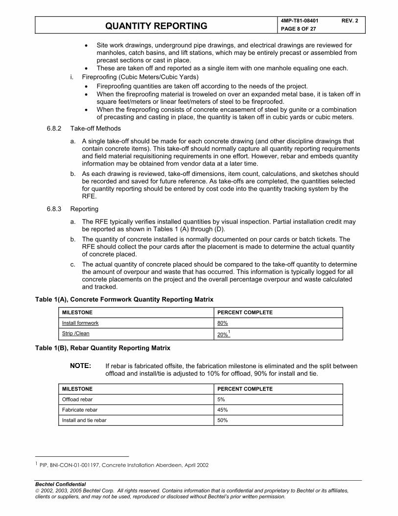
a. The RFE typically verifies installed quantities by visual inspection. Partial installation credit may be reported as shown in Tables 1 (A) through (D).
b. The quantity of concrete installed is normally documented on pour cards or batch tickets. The RFE should collect the pour cards after the placement is made to determine the actual quantity of concrete placed.
c. The actual quantity of concrete placed should be compared to the take-off quantity to determine the amount of overpour and waste that has occurred. This information is typically logged for all concrete placements on the project and the overall percentage overpour and waste calculated and tracked.
Table 1(A), Concrete Formwork Quantity Reporting Matrix
Table 1(B), Rebar Quantity Reporting Matrix
If rebar is fabricated offsite, the fabrication milestone is eliminated and the split between offload and install/tie is adjusted to 10% for offload, 90% for install and tie.
MILESTONE PERCENT COMPLETE
Offload rebar 5%
Fabricate rebar 45%
Install and tie rebar 50%
1 PIP, BNI-CON-01-001197, Concrete Installation Aberdeen, April 2002
MILESTONE PERCENT COMPLETE
Install formwork 80%
Strip /Clean 20%1

4MP-T81-08401 REV. 2QUANTITY REPORTING PAGE 9 OF 27
Bechtel Confidential 2002, 2003, 2005 Bechtel Corp. All rights reserved. Contains information that is confidential and proprietary to Bechtel or its affiliates, clients or suppliers, and may not be used, reproduced or disclosed without Bechtel’s prior written permission.
Table 1(C), Embed Quantity Reporting Matrix
As an option, embed reporting may be combined with formwork. When this occurs, embed installation should be included as part of formwork installation.
MILESTONE PERCENT COMPLETE
Offload, build templates and set embeds 80%
Concrete placement and remove templates 20%
Table 1(D), Concrete Quantity Reporting Matrix
MILESTONE PERCENT COMPLETE
Concrete placement 90%
Patch concrete and final cleanup 8%
Field Engineering Inspection Complete, Acceptable and Ready to Test
2%
6.9 Structural Steel
6.9.1 Take-off
a. The take-off format for structural steel must follow the project code of accounts. The Quantity Reporting Plan should identify how items such as grating, handrail and toeplate, stair tread, etc., will be quantified.
b. Structural steel is taken off as tons/metric tons and is normally organized and compiled by cost code, drawing numbers, and structure.
c. In some cases, further information (such as elevation and bay) is used in the take-off and reporting of major multilevel structures such as boiler buildings.
d. The RFE should maintain a complete set of fabricator erection drawings showing the fabricator's piece marks used for the take-off. The RFE should also track the delivery status and installed status of each piece of steel. One method of doing this is to mark-up the erection drawings using a color code.
e. In some cases, take-off quantities can be electronically developed by the steel fabricator and electronically downloaded into TEAMWorks. When this occurs, the RFE should make sure quantities are accurate and updated with any changes that occur. Quantities should be available before the steel is received on site. Vendor documents are often available that list the piece marks with weights for all fabricated steel by drawing number.
6.9.2 Reporting
a. The RFE normally verifies installed quantities by visual inspection of the completed work. Partial installation credit shall be reported as shown in Table 2.
b. RFE should maintain both a marked-up set of drawings showing installed quantities and a log of weekly installed quantities that have been reported.
c. Grouting of associated base plates is normally included in the steel account and should be considered as part of the installation (welded or bolted) milestone.
Table 2, Structural Steel Reporting Matrix
OFFLOAD & HAUL ERECTED & TACKED WELDED OR
BOLTEDFIELD ENGINEERING INSPECTION
COMPLETEAND ACCEPTABLE AND READY TO TEST
Platform, stairs, ladders 5% 45% 35% 15%Grating, checker plate 5% 45% 35% 15%Pipe stanchions 5% 65% 15% 15%Steel structures 5% 50% 25% 20%Handrail systems 5% 50% 35% 10%
4MP-T81-08401 REV. 2QUANTITY REPORTING PAGE 10 OF 27
Bechtel Confidential 2002, 2003, 2005 Bechtel Corp. All rights reserved. Contains information that is confidential and proprietary to Bechtel or its affiliates, clients or suppliers, and may not be used, reproduced or disclosed without Bechtel’s prior written permission.
6.10 Buildings
6.10.1 Take-off
a. The take-off for buildings should be performed for each building for major work items such as brick/block, building structural steel, siding and roofing, doors and windows, plumbing, electrical, HVAC, F&G and architectural finishes. Building foundations should be included with the concrete accounts.
b. It is important to clearly identify the boundaries of take-off responsibility between buildings and other disciplines, especially piping and electrical. The normal limit for this boundary is 5 feet (1.5 meters) outside the building outline.
6.10.2 Reporting
Building installed quantities are normally reported by each discipline as outlined in each section of this SWPP. However, if the building is subcontracted, a separate report may be submitted for all disciplines in the subcontractor's scope of work.
6.11 Mechanical Equipment
6.11.1 Take-off
The mechanical equipment take-off is developed by cost code from the design engineering equipment list. Data is normally electronically fed into QRS. The RFE is responsible for setting up the appropriate quantity reporting ledger.
a. The RFE should review the vendor drawings to identify loose commodities supplied with the mechanical equipment that must be field installed. Depending on the project code of accounts, the RFE may need to perform separate take-offs of these quantities.
b. In general, mechanical equipment may be reported as anywhere from 20 to 80 percent complete when set on foundations and 100 percent complete after final alignment and grouting.
c. In developing the plan for reporting installed mechanical equipment quantities, a thorough review of the equipment installation procedure and schedule must be made by the RFE and RS to determine installation milestones that can be used to monitor the installation process.
d. This weighting should take into consideration the job hours and percentage of the budget required to achieve the milestone. Based on these weighting factors, the installation is reported as a percent complete for the overall installation.
e. The QRS application has significant direction on the identified milestones, activities, and related weightings.
f. When the weighting factors are developed, the installation of loose commodities and special work processes, such as alignment, must be taken into account as one of the basic milestones in completing the overall installation since this effort can represent a significant portion of the budgeted jobhours.
6.11.2 Reporting
a. The RFE normally verifies installed quantities by visual inspection of the completed work. The complete installation of mechanical equipment should include final alignment.
b. Typical examples of Major Equipment Detailed Work Operations reporting percentages are shown in Table 3.
4MP-T81-08401 REV. 2QUANTITY REPORTING PAGE 11 OF 27
Bechtel Confidential 2002, 2003, 2005 Bechtel Corp. All rights reserved. Contains information that is confidential and proprietary to Bechtel or its affiliates, clients or suppliers, and may not be used, reproduced or disclosed without Bechtel’s prior written permission.
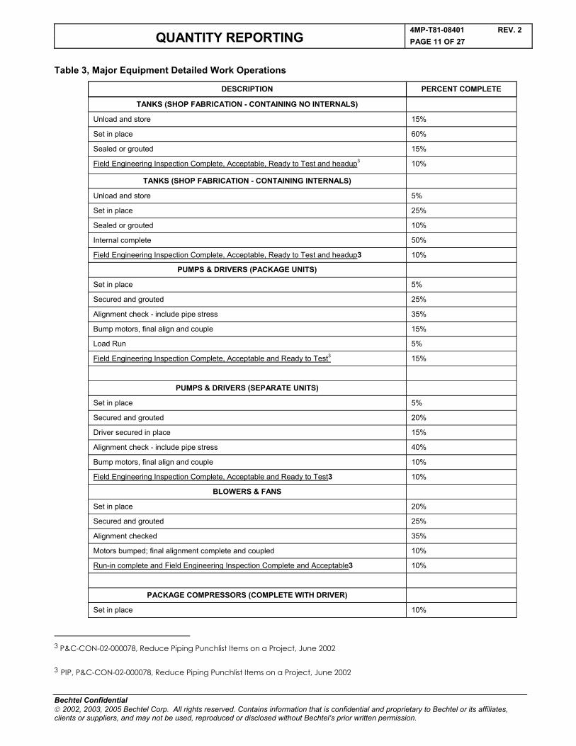
Table 3, Major Equipment Detailed Work Operations
DESCRIPTION PERCENT COMPLETE
TANKS (SHOP FABRICATION - CONTAINING NO INTERNALS)
Unload and store 15%
Set in place 60%
Sealed or grouted 15%
Field Engineering Inspection Complete, Acceptable, Ready to Test and headup3 10%
TANKS (SHOP FABRICATION - CONTAINING INTERNALS)
Unload and store 5%
Set in place 25%
Sealed or grouted 10%
Internal complete 50%
Field Engineering Inspection Complete, Acceptable, Ready to Test and headup3 10%
PUMPS & DRIVERS (PACKAGE UNITS)
Set in place 5%
Secured and grouted 25%
Alignment check - include pipe stress 35%
Bump motors, final align and couple 15%
Load Run 5%
Field Engineering Inspection Complete, Acceptable and Ready to Test3 15%
PUMPS & DRIVERS (SEPARATE UNITS)
Set in place 5%
Secured and grouted 20%
Driver secured in place 15%
Alignment check - include pipe stress 40%
Bump motors, final align and couple 10%
Field Engineering Inspection Complete, Acceptable and Ready to Test3 10%
BLOWERS & FANS
Set in place 20%
Secured and grouted 25%
Alignment checked 35%
Motors bumped; final alignment complete and coupled 10%
Run-in complete and Field Engineering Inspection Complete and Acceptable3 10%
PACKAGE COMPRESSORS (COMPLETE WITH DRIVER)
Set in place 10%
3 P&C-CON-02-000078, Reduce Piping Punchlist Items on a Project, June 2002
3 PIP, P&C-CON-02-000078, Reduce Piping Punchlist Items on a Project, June 2002
4MP-T81-08401 REV. 2QUANTITY REPORTING PAGE 12 OF 27
Bechtel Confidential 2002, 2003, 2005 Bechtel Corp. All rights reserved. Contains information that is confidential and proprietary to Bechtel or its affiliates, clients or suppliers, and may not be used, reproduced or disclosed without Bechtel’s prior written permission.
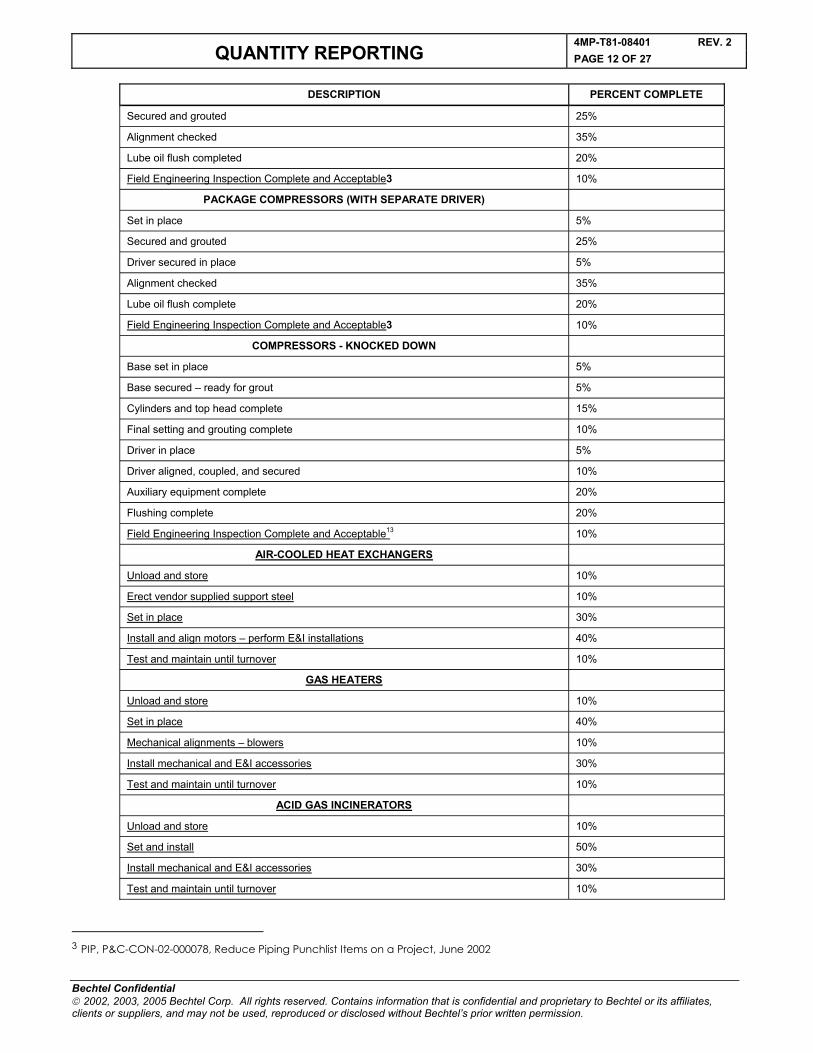
DESCRIPTION PERCENT COMPLETE
Secured and grouted 25%
Alignment checked 35%
Lube oil flush completed 20%
Field Engineering Inspection Complete and Acceptable3 10%
PACKAGE COMPRESSORS (WITH SEPARATE DRIVER)
Set in place 5%
Secured and grouted 25%
Driver secured in place 5%
Alignment checked 35%
Lube oil flush complete 20%
Field Engineering Inspection Complete and Acceptable3 10%
COMPRESSORS - KNOCKED DOWN
Base set in place 5%
Base secured – ready for grout 5%
Cylinders and top head complete 15%
Final setting and grouting complete 10%
Driver in place 5%
Driver aligned, coupled, and secured 10%
Auxiliary equipment complete 20%
Flushing complete 20%
Field Engineering Inspection Complete and Acceptable13 10%
AIR-COOLED HEAT EXCHANGERS
Unload and store 10%
Erect vendor supplied support steel 10%
Set in place 30%
Install and align motors – perform E&I installations 40%
Test and maintain until turnover 10%
GAS HEATERS
Unload and store 10%
Set in place 40%
Mechanical alignments – blowers 10%
Install mechanical and E&I accessories 30%
Test and maintain until turnover 10%
ACID GAS INCINERATORS
Unload and store 10%
Set and install 50%
Install mechanical and E&I accessories 30%
Test and maintain until turnover 10%
3 PIP, P&C-CON-02-000078, Reduce Piping Punchlist Items on a Project, June 2002
4MP-T81-08401 REV. 2QUANTITY REPORTING PAGE 13 OF 27
Bechtel Confidential 2002, 2003, 2005 Bechtel Corp. All rights reserved. Contains information that is confidential and proprietary to Bechtel or its affiliates, clients or suppliers, and may not be used, reproduced or disclosed without Bechtel’s prior written permission.
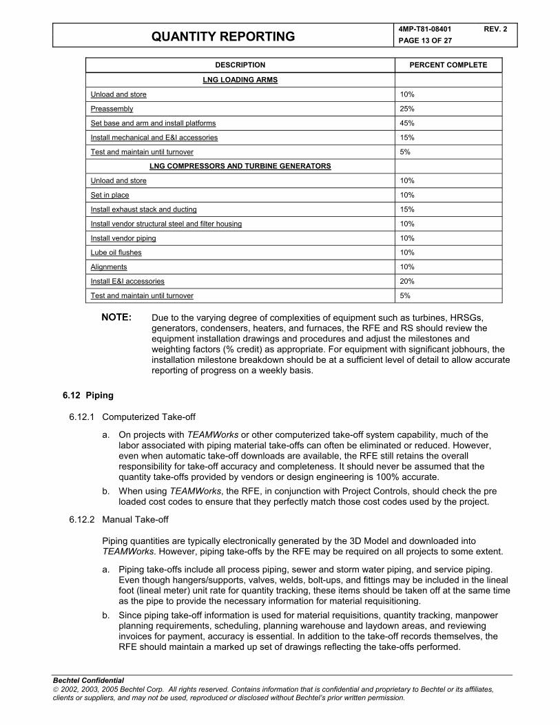
DESCRIPTION PERCENT COMPLETE
LNG LOADING ARMS
Unload and store 10%
Preassembly 25%
Set base and arm and install platforms 45%
Install mechanical and E&I accessories 15%
Test and maintain until turnover 5%
LNG COMPRESSORS AND TURBINE GENERATORS
Unload and store 10%
Set in place 10%
Install exhaust stack and ducting 15%
Install vendor structural steel and filter housing 10%
Install vendor piping 10%
Lube oil flushes 10%
Alignments 10%
Install E&I accessories 20%
Test and maintain until turnover 5%
Due to the varying degree of complexities of equipment such as turbines, HRSGs, generators, condensers, heaters, and furnaces, the RFE and RS should review the equipment installation drawings and procedures and adjust the milestones and weighting factors (% credit) as appropriate. For equipment with significant jobhours, the installation milestone breakdown should be at a sufficient level of detail to allow accurate reporting of progress on a weekly basis.
6.12 Piping
6.12.1 Computerized Take-off
a. On projects with TEAMWorks or other computerized take-off system capability, much of the labor associated with piping material take-offs can often be eliminated or reduced. However, even when automatic take-off downloads are available, the RFE still retains the overall responsibility for take-off accuracy and completeness. It should never be assumed that the quantity take-offs provided by vendors or design engineering is 100% accurate.
b. When using TEAMWorks, the RFE, in conjunction with Project Controls, should check the pre loaded cost codes to ensure that they perfectly match those cost codes used by the project.
6.12.2 Manual Take-off
Piping quantities are typically electronically generated by the 3D Model and downloaded into TEAMWorks. However, piping take-offs by the RFE may be required on all projects to some extent.
a. Piping take-offs include all process piping, sewer and storm water piping, and service piping. Even though hangers/supports, valves, welds, bolt-ups, and fittings may be included in the lineal foot (lineal meter) unit rate for quantity tracking, these items should be taken off at the same time as the pipe to provide the necessary information for material requisitioning.
b. Since piping take-off information is used for material requisitions, quantity tracking, manpower planning requirements, scheduling, planning warehouse and laydown areas, and reviewing invoices for payment, accuracy is essential. In addition to the take-off records themselves, the RFE should maintain a marked up set of drawings reflecting the take-offs performed.
4MP-T81-08401 REV. 2QUANTITY REPORTING PAGE 14 OF 27
Bechtel Confidential 2002, 2003, 2005 Bechtel Corp. All rights reserved. Contains information that is confidential and proprietary to Bechtel or its affiliates, clients or suppliers, and may not be used, reproduced or disclosed without Bechtel’s prior written permission.
c. Pipe length is taken from dimensional drawings, never from P&IDs. Changes in direction (fittings) are measured from intersection of straight centerlines. Footage/linear meters is measured through fittings, valves, and specialties but not equipment.
d. Piping drawings and P&IDs should show all pipe line numbers. The Line Designation Table or Line List usually describes beginning and ending points for each line. P&IDs, the Line Designation Table, layout drawings, isometrics, and other project drawings are all required to make an accurate piping take-off.
e. When the piping take-off is complete, the Line Designation Table, P&IDs, isometrics, and layout drawings should be compared to determine any lines not included in the take-off. The most common discrepancy is two-inch and smaller lines shown only on P&IDs with no line number assigned. These lines are typically routed at the site and the Design Engineering group should be notified to assign an appropriate line number.
f. Shop fabricated pipe is a separate take-off. Depending on the project, some of the pipe will be shop fabricated and delivered in spools to the jobsite. Isometric and orthographic drawings should be clearly marked to identify field welds and pipe length to be spooled prior to vendor fabrication. This pipe is taken off by spool number. Each spool take-off should be labeled with a code corresponding to the drawing and spool number. Straight run pipe lengths that will not be vendor fabricated should be identified on the isometric drawings.
g. Equipment drawings for package systems, skid mounted equipment, etc., should be reviewed to ensure that all materials, especially valves, are either vendor furnished or included in the field piping take-off. These items may be marked as supplied by others. Installation and reporting of piping supplied by an equipment vendor is normally included in the mechanical equipment accounts.
h. Pipe materials for temporary construction quantities should not be included in the total installed quantities required for project quantity reporting.
i. Pipe support/hanger and stanchion take-offs are required for installed quantity reporting and/or material requisitioning. On some projects (i.e., Power) uniquely designed supports are tracked in a separate account.
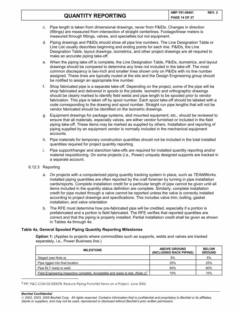
6.12.3 Reporting
a. On projects with a computerized piping quantity tracking system in place, such as TEAMWorks,installed piping quantities are often reported by the craft foreman by turning in pipe installation cards/reports. Complete installation credit for a particular length of pipe cannot be given until all items included in the quantity status definition are complete. Similarly, complete installation credit for pipe routed through a valve cannot be reported unless the valve is correctly installed according to project drawings and specifications. This includes valve trim, bolting, gasket installation, and valve orientation
b. The RFE must determine how pre-fabricated pipe will be credited, especially if a portion is prefabricated and a portion is field fabricated. The RFE verifies that reported quantities are correct and that the piping is properly installed. Partial installation credit shall be given as shown in Tables 4a through 4e.
Table 4a, General Spooled Piping Quantity Reporting Milestones
Option 1: (Applies to projects where commodities such as supports, welds and valves are tracked separately, i.e., Power Business line.)
MILESTONE ABOVE GROUND (INCLUDING RACK PIPING)
BELOW GROUND
Staged (see Note a) 5% 5%Pipe rigged into final location 25% 25%Pipe ELT ready to weld 60% 60%Field Engineering Inspection complete, Acceptable and ready to test. (Note c)3 10% 10%
3 PIP, P&C-CON-02-000078, Reduce Piping Punchlist Items on a Project, June 2002
4MP-T81-08401 REV. 2QUANTITY REPORTING PAGE 15 OF 27
Bechtel Confidential 2002, 2003, 2005 Bechtel Corp. All rights reserved. Contains information that is confidential and proprietary to Bechtel or its affiliates, clients or suppliers, and may not be used, reproduced or disclosed without Bechtel’s prior written permission.
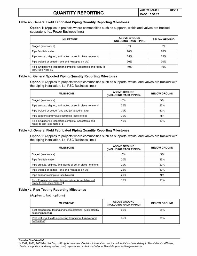
Table 4b, General Field Fabricated Piping Quantity Reporting Milestones
Option 1: (Applies to projects where commodities such as supports, welds and valves are tracked separately, i.e., Power Business line.)
MILESTONE ABOVE GROUND (INCLUDING RACK PIPING) BELOW GROUND
Staged (see Note a) 5% 5%
Pipe field fabrication 20% 20%
Pipe erected, aligned, and tacked or set in place - one end 35% 35%
Pipe welded or bolted – one end (wrapped on u/g) 30% 30%
Field Engineering Inspection complete, Acceptable and ready to test. (See Note c)3
10% 10%
Table 4c, General Spooled Piping Quantity Reporting Milestones
Option 2: (Applies to projects where commodities such as supports, welds, and valves are tracked with the piping installation, i.e. P&C Business line.)
MILESTONE ABOVE GROUND (INCLUDING RACK PIPING) BELOW GROUND
Staged (see Note a) 5% 5%
Pipe erected, aligned, and tacked or set in place - one end 25% 25%
Pipe welded or bolted - one end (wrapped on u/g) 30% 60%
Pipe supports and valves complete (see Note b) 30% N/A
Field Engineering Inspection complete, Acceptable and ready to test (See Note c) 3
10% 10%
Table 4d, General Field Fabricated Piping Quantity Reporting Milestones
Option 2: (Applies to projects where commodities such as supports, welds, and valves are tracked with the piping installation, i.e. P&C Business line.)
MILESTONE ABOVE GROUND (INCLUDING RACK PIPING) BELOW GROUND
Staged (see Note a) 5% 5%
Pipe field fabrication 20% 35%
Pipe erected, aligned, and tacked or set in place - one end 20% 20%
Pipe welded or bolted – one end (wrapped on u/g) 25% 30%
Pipe supports complete (see Note b) 20% N/A
Field Engineering Inspection complete, Acceptable and ready to test. (See Note c) 3
10% 10%
Table 4e, Pipe Testing Reporting Milestones
(Applies to both options)
MILESTONE ABOVE GROUND (INCLUDING RACK PIPING) BELOW GROUND
Test preparation, testing and test restoration. (Validated by field engineering)
65% 65%
Post test final Field Engineering Inspection, turnover and acceptance1
35% 35%

4MP-T81-08401 REV. 2QUANTITY REPORTING PAGE 16 OF 27
Bechtel Confidential 2002, 2003, 2005 Bechtel Corp. All rights reserved. Contains information that is confidential and proprietary to Bechtel or its affiliates, clients or suppliers, and may not be used, reproduced or disclosed without Bechtel’s prior written permission.
Notes:a. Staging includes either moving material from the Laydown Yard/Warehouse to the area of
installation, or offloading delivered material at the point of installation.b. Deviations from the rules of credit indicated above require an SWPP deviation and MOC approval.c. This reporting milestone is not to be used to complete remaining work items or to repair work
previously reported as fully complete. The line at this stage of progress should be walked down and validated against the isometric and P&IDs by the RFE. The RSs and RFEs should target Zero Punchlist Items associated with completed work activities. Punchlist items (Including client punchlist) should be identified and assessed for pre-turnover completion. This does not include test blind installation.3
d. Field Engineering Inspection3 includes operational checks of valve handwheels, chain operators, and restraightening small diameter pipe. This does not include removal of test blinds and rebolting flanges after testing.
e. Installation rates normally exclude scaffolding and material handling (refer to Standard Code of Accounts). This should be confirmed.
f. RFE should maintain both a marked up set of drawings and data records reflecting take-off, material, and installation status.
g. Tagged inline instruments and instrument air headers reporting is the responsibility of piping group.
6.13 Electrical
6.13.1 Take-off
a. Power and control conduit is taken off by drawing, size, and type. Individual conduit runs are listed by electrical device such as motor, panel, or control station.
b. Lighting and instrument conduit is taken off by drawing, size, and type. Conduit runs are listed by geographical area, junction box, elevation, or equipment number. Conduits should be numbered to provide easier quantity tracking.
c. When a computerized quantity tracking program like SETROUTE is not available at the project site, the RFE should maintain a complete set of take-off drawings reflecting the take-off performed. Any allowances for omitted dimensions, such as elevation changes, should be indicated on the marked up take-off drawings.
d. Cable tray, tray hangers, and tray covers are taken off by drawing and size. The take-off should include fittings by type and size. The RFE should maintain a set of marked up drawings reflecting the take-off.
e. Wire and cable take-offs are based on the project circuit and raceway schedule. The circuit schedule must be reviewed carefully to ensure that it includes all instrument wire circuits, special vendor wire requirements, communication systems, lighting circuits, and electric heat tracing circuits. The take-off boundaries between building accounts and electrical accounts must be clearly defined so that all building circuits are taken off.
f. Nonscheduled wire and cable (typically lighting circuits and instrument wiring from junction boxes to field mounted devices) are taken off or estimated by wire and cable type by lighting or instrument location drawings.
g. The wire and cable take-off quantity is the "pulled" linear feet/meters including tails. The normal tail length is 5 feet (1.5 meters) per end on 5 kV and larger cable and 10 feet (3 meters) per end on all other wire and cable. For scheduled wire and cable, the “Engineered” cable length as
2 PIP POWER-ENG-01-00011, Electrical Cable Installation Waste Issues, February 2002
3 PIP, P&C-CON-02-000078, Reduce Piping Punchlist Items on a Project, June 2002

4MP-T81-08401 REV. 2QUANTITY REPORTING PAGE 17 OF 27
Bechtel Confidential 2002, 2003, 2005 Bechtel Corp. All rights reserved. Contains information that is confidential and proprietary to Bechtel or its affiliates, clients or suppliers, and may not be used, reproduced or disclosed without Bechtel’s prior written permission.
reported by SETROUTE is to be used as the take-off quantity. This Engineered length is effectively the “pulled” linear feet/meters including tails, since SETROUTE calculates the “Engineered” length by summing the length of the raceway in which the cable is routed, and adding on a default tail end length to each cable end. The raceway lengths used by SETROUTE to calculate the cable “Engineered” length (e.g. the take-off length) is either the “Engineered” (estimated) raceway length or the actual installed raceway length, depending on the status of the raceway installation. 2
h. Terminations are normally taken off at the same time as the wire and cable. The termination take-off equals the number of conductors in the cable times two, less spares. The termination take-off should also include the ground wire as a conductor. Lighting system terminations are not normally included in the take-off.
i. Power and control equipment such as pushbutton stations, junction boxes, distribution panels, and receptacles are normally taken off by drawing and grouped by device type. As with other take-off activities, a set of marked up drawings should be maintained documenting the take-off performed.
j. Lighting equipment including light fixtures, lighting contactors and switches, lighting panels, lighting transformers, and receptacles on lighting circuits is normally taken off by drawing and grouped by device type.
k. Grounding is taken off by drawing, conductor, size, and type. The grounding drawings are marked up as take-offs are done and maintained in the RFEs file. Ground rods are taken off in “eaches” and included in the take-off. If they are not shown on the drawings, include allowances for pigtails to motors and electrical equipment. All raceway (Tray and Conduit) and misc. equipment grounds are included in the quantity reporting for each of those specific commodity installations and unit rates therefore not required to be tracked and reported separately.4
l. ISO-Phase quantities are taken off using issued IFC drawing, (Bechtel and/or Vendor) by number of bus sections individually for Main Bus and Auxiliary Bus. Main Bus is identified as the sections between the Transformer to Generator Breaker to Exciter and Generator. Auxiliary Bus is identified as the section drops from the Main Bus to the individual components or equipment. ISO-Phase is considered Electrical Equipment and shall be credited as installation progresses and reported by bus type (Main and Auxiliary) to the Project Field Controls department as defined in Table 5. As with other take-off activities, a set of marked up drawings should be maintained documenting the take-off preformed and highlighted as components are completed to track installation status.4
6.13.2 Reporting
a. On projects using the SETROUTE quantity tracking program, the electrical craft foreman normally reports installed quantities by completing and submitting an installation card documenting the work performed. The program will then credit the linear feet of wire and cable installed, terminations completed, or devices set. Installation of raceway is not complete unless all trays are secured and all supports, caps, and plugs are in place.
SETROUTE allows three separate cable lengths to be tracked in the SETROUTE databases. ALL quantity reporting for scheduled cables shall be based upon the Engineered Lengths shown in SETROUTE:
Engineered Length – a length calculated by SETROUTE as described in Section 14.1 above, based upon the length of the raceway the cable is routed within
2 PIP POWER-ENG-01-00011, Electrical Cable Installation Waste Issues, February 2002
3 PIP, P&C-CON-02-000078, Reduce Piping Punchlist Items on a Project, June 2002
4 PIP, Power-CON-03-000001, Isophase – Constructability Approach, October 2003 and PIP, Power-CON-03-113767, In-Plant Electrical Grounding, February 2004
4MP-T81-08401 REV. 2QUANTITY REPORTING PAGE 18 OF 27
Bechtel Confidential 2002, 2003, 2005 Bechtel Corp. All rights reserved. Contains information that is confidential and proprietary to Bechtel or its affiliates, clients or suppliers, and may not be used, reproduced or disclosed without Bechtel’s prior written permission.
Actual Length – the final installed length (e.g. trimmed length) as reported by feedback on the cable installation card by Construction
Cut Length – tracked against the cable reel quantity, the actual length cut from the associated cable reel as reported by feedback on the cable installation card by Construction1
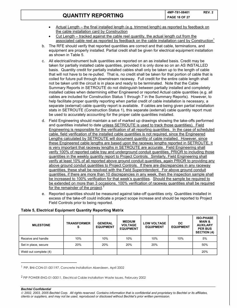
b. The RFE should verify that reported quantities are correct and that cable, terminations, and equipment are properly installed. Partial credit shall be given for electrical equipment installation as shown in Table 5.
c. All electrical/instrument bulk quantities are reported on an as installed basis. Credit may be taken for partially installed cable quantities, provided it is only done so on an AS INSTALLED basis. Quantity credit for partially installed cables shall only be taken up to the length of cable that will not have to be re-pulled. That is, no credit shall be taken for that portion of cable that is coiled for future pull through downstream raceway. Full credit for the entire cable length shall not be taken until the circuit is in place and ready to be terminated. Note that the Cable Summary Reports in SETROUTE do not distinguish between partially installed and completely installed cables when determining either Engineered or reported Actual cable quantities (e.g. all cables are included for Construction Status 1 through 7 in the Summary Reports). However, to help facilitate proper quantity reporting when partial credit of cable installation is necessary, a separate (external) cable quantity report is available. If cables are being given partial installation stats in SETROUTE (Construction Status 1), this separate (external) cable quantity report must be used to accurately accounting for the proper cable quantities installed.
d. Field Engineering should maintain a set of marked up drawings showing the take-offs performed and quantities installed to date unless SETROUTE is used to track those quantities). Field Engineering is responsible for the verification of all reporting quantities. In the case of scheduled cable, field verification of the installed cable quantities is not required, since the Engineered Lengths calculated by SETROUTE will document quantity of cable installed. However, since these Engineered cable lengths are based upon the raceway lengths reported in SETROUTE, it is very important that raceway lengths in SETROUTE are accurate. Field Engineering shall verify 100% of reported cable tray and underground conduit quantities, PRIOR to including those quantities in the weekly quantity report to Project Controls. Similarly, Field Engineering shall verify at least 10% of all reported above ground conduit quantities, again PRIOR to providing any above ground conduit quantities to Project Controls. If there are discrepancies in any raceway quantities, these shall be resolved with the Field Superintendent. For above ground conduit quantities, if there are more than 10 discrepancies in any week, then the inspection sample shall be increased to 100% verification for that week’s quantities. Should the sample be required to be extended on more than 3 occasions, 100% verification of raceway quantities shall be required for the remainder of the project.2
e. Reported quantities should be measured against take-off quantities only. Quantities installed in excess of the take-off could indicate a project scope increase and should be reported to Project Field Controls prior to being reported.
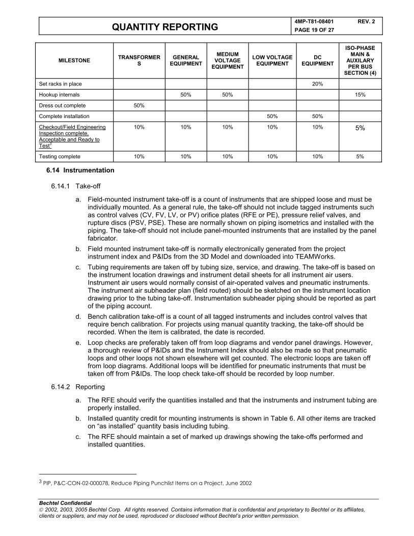
Table 5, Electrical Equipment Quantity Reporting Matrix
MILESTONE TRANSFORMERS
GENERAL EQUIPMENT
MEDIUM VOLTAGE
EQUIPMENTLOW VOLTAGE
EQUIPMENTDC
EQUIPMENT
ISO-PHASE MAIN &
AUXILARY PER BUS
SECTION (4)
Receive and handle 10% 10% 10% 10% 10% 5%
Set in place, secure 20% 20% 20% 20% 50%
Weld out complete (4) 20%
1 PIP, BNI-CON-01-001197, Concrete Installation Aberdeen, April 2002
2 PIP POWER-ENG-01-00011, Electrical Cable Installation Waste Issues, February 2002
4MP-T81-08401 REV. 2QUANTITY REPORTING PAGE 19 OF 27
Bechtel Confidential 2002, 2003, 2005 Bechtel Corp. All rights reserved. Contains information that is confidential and proprietary to Bechtel or its affiliates, clients or suppliers, and may not be used, reproduced or disclosed without Bechtel’s prior written permission.
MILESTONE TRANSFORMERS
GENERAL EQUIPMENT
MEDIUM VOLTAGE
EQUIPMENTLOW VOLTAGE
EQUIPMENTDC
EQUIPMENT
ISO-PHASE MAIN &
AUXILARY PER BUS
SECTION (4)
Set racks in place 20%
Hookup internals 50% 50% 15%
Dress out complete 50%
Complete installation 50% 50%
Checkout/Field Engineering Inspection complete, Acceptable and Ready to Test3
10% 10% 10% 10% 10% 5%
Testing complete 10% 10% 10% 10% 10% 5%
6.14 Instrumentation
6.14.1 Take-off
a. Field-mounted instrument take-off is a count of instruments that are shipped loose and must be individually mounted. As a general rule, the take-off should not include tagged instruments such as control valves (CV, FV, LV, or PV) orifice plates (RFE or PE), pressure relief valves, and rupture discs (PSV, PSE). These are normally shown on piping isometrics and installed with the piping. The take-off should not include panel-mounted instruments that are installed by the panel fabricator.
b. Field mounted instrument take-off is normally electronically generated from the project instrument index and P&IDs from the 3D Model and downloaded into TEAMWorks.
c. Tubing requirements are taken off by tubing size, service, and drawing. The take-off is based on the instrument location drawings and instrument detail sheets for all instrument air users. Instrument air users would normally consist of air-operated valves and pneumatic instruments. The instrument air subheader plan (field routed) should be sketched on the instrument location drawing prior to the tubing take-off. Instrumentation subheader piping should be reported as part of the piping account.
d. Bench calibration take-off is a count of all tagged instruments and includes control valves that require bench calibration. For projects using manual quantity tracking, the take-off should be recorded. When the item is calibrated, the date is recorded.
e. Loop checks are preferably taken off from loop diagrams and vendor panel drawings. However, a thorough review of P&IDs and the Instrument Index should also be made so that pneumatic loops and other loops not shown elsewhere will get counted. The electronic loops are taken off from loop diagrams. Additional loops will be identified for pneumatic instruments that must be taken off from P&IDs. The loop check take-off should be recorded by loop number.
6.14.2 Reporting
a. The RFE should verify the quantities installed and that the instruments and instrument tubing are properly installed.
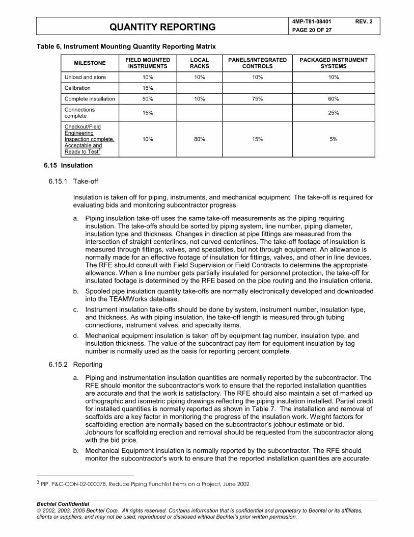
b. Installed quantity credit for mounting instruments is shown in Table 6. All other items are tracked on “as installed” quantity basis including tubing.
c. The RFE should maintain a set of marked up drawings showing the take-offs performed and installed quantities.
3 PIP, P&C-CON-02-000078, Reduce Piping Punchlist Items on a Project, June 2002
4MP-T81-08401 REV. 2QUANTITY REPORTING PAGE 20 OF 27
Bechtel Confidential 2002, 2003, 2005 Bechtel Corp. All rights reserved. Contains information that is confidential and proprietary to Bechtel or its affiliates, clients or suppliers, and may not be used, reproduced or disclosed without Bechtel’s prior written permission.
Table 6, Instrument Mounting Quantity Reporting Matrix
MILESTONE FIELD MOUNTED INSTRUMENTS
LOCAL RACKS
PANELS/INTEGRATED CONTROLS
PACKAGED INSTRUMENT SYSTEMS
Unload and store 10% 10% 10% 10%
Calibration 15%
Complete installation 50% 10% 75% 60%
Connections complete 15% 25%
Checkout/Field Engineering Inspection complete, Acceptable and Ready to Test3
10% 80% 15% 5%
6.15 Insulation
6.15.1 Take-off
Insulation is taken off for piping, instruments, and mechanical equipment. The take-off is required for evaluating bids and monitoring subcontractor progress.
a. Piping insulation take-off uses the same take-off measurements as the piping requiring insulation. The take-offs should be sorted by piping system, line number, piping diameter, insulation type and thickness. Changes in direction at pipe fittings are measured from the intersection of straight centerlines, not curved centerlines. The take-off footage of insulation is measured through fittings, valves, and specialties, but not through equipment. An allowance is normally made for an effective footage of insulation for fittings, valves, and other in line devices. The RFE should consult with Field Supervision or Field Contracts to determine the appropriate allowance. When a line number gets partially insulated for personnel protection, the take-off for insulated footage is determined by the RFE based on the pipe routing and the insulation criteria.
b. Spooled pipe insulation quantity take-offs are normally electronically developed and downloaded into the TEAMWorks database.
c. Instrument insulation take-offs should be done by system, instrument number, insulation type, and thickness. As with piping insulation, the take-off length is measured through tubing connections, instrument valves, and specialty items.
d. Mechanical equipment insulation is taken off by equipment tag number, insulation type, and insulation thickness. The value of the subcontract pay item for equipment insulation by tag number is normally used as the basis for reporting percent complete.
6.15.2 Reporting
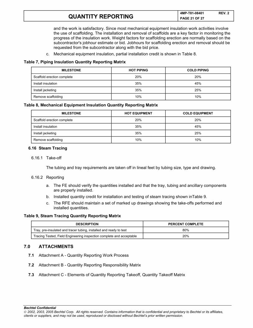
a. Piping and instrumentation insulation quantities are normally reported by the subcontractor. The RFE should monitor the subcontractor's work to ensure that the reported installation quantities are accurate and that the work is satisfactory. The RFE should also maintain a set of marked up orthographic and isometric piping drawings reflecting the piping insulation installed. Partial credit for installed quantities is normally reported as shown in Table 7. The installation and removal of scaffolds are a key factor in monitoring the progress of the insulation work. Weight factors for scaffolding erection are normally based on the subcontractor’s jobhour estimate or bid. Jobhours for scaffolding erection and removal should be requested from the subcontractor along with the bid price.
b. Mechanical Equipment insulation is normally reported by the subcontractor. The RFE should monitor the subcontractor's work to ensure that the reported installation quantities are accurate
3 PIP, P&C-CON-02-000078, Reduce Piping Punchlist Items on a Project, June 2002
4MP-T81-08401 REV. 2QUANTITY REPORTING PAGE 21 OF 27
Bechtel Confidential 2002, 2003, 2005 Bechtel Corp. All rights reserved. Contains information that is confidential and proprietary to Bechtel or its affiliates, clients or suppliers, and may not be used, reproduced or disclosed without Bechtel’s prior written permission.
and the work is satisfactory. Since most mechanical equipment insulation work activities involve the use of scaffolding. The installation and removal of scaffolds are a key factor in monitoring the progress of the insulation work. Weight factors for scaffolding erection are normally based on the subcontractor's jobhour estimate or bid. Jobhours for scaffolding erection and removal should be requested from the subcontractor along with the bid price.
c. Mechanical equipment insulation, partial installation credit is shown in Table 8.
Table 7, Piping Insulation Quantity Reporting Matrix
MILESTONE HOT PIPING COLD PIPING
Scaffold erection complete 20% 20%
Install insulation 35% 45%
Install jacketing 35% 25%
Remove scaffolding 10% 10%
Table 8, Mechanical Equipment Insulation Quantity Reporting Matrix
MILESTONE HOT EQUIPMENT COLD EQUIPMENT
Scaffold erection complete 20% 20%
Install insulation 35% 45%
Install jacketing 35% 25%
Remove scaffolding 10% 10%
6.16 Steam Tracing
6.16.1 Take-off
The tubing and tray requirements are taken off in lineal feet by tubing size, type and drawing.
6.16.2 Reporting
a. The FE should verify the quantities installed and that the tray, tubing and ancillary components are properly installed.
b. Installed quantity credit for installation and testing of steam tracing shown inTable 9.c. The RFE should maintain a set of marked up drawings showing the take-offs performed and
installed quantities.
Table 9, Steam Tracing Quantity Reporting Matrix
DESCRIPTION PERCENT COMPLETE
Tray, pre-insulated and tracer tubing, installed and ready to test 80%
Tracing Tested, Field Engineering inspection complete and acceptable 20%
7.0 ATTACHMENTS
7.1 Attachment A - Quantity Reporting Work Process
7.2 Attachment B - Quantity Reporting Responsibility Matrix
7.3 Attachment C - Elements of Quantity Reporting Takeoff, Quantity Takeoff Matrix
4MP-T81-08401 REV. 2QUANTITY REPORTING PAGE 22 OF 27
Bechtel Confidential 2001,2003, 2005 Bechtel Corp. All rights reserved. Contains information that is confidential and proprietary to Bechtel or its affiliates, clients or suppliers, and may not to be used, reproduced or disclosed without Bechtel’s prior written permission.
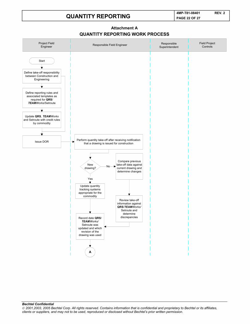
Attachment AQUANTITY REPORTING WORK PROCESS
Project FieldEngineer Responsible Field Engineer Responsible
SuperintendentField Project
Controls
Start
Define take-off responsibilitybetween Construction and
Engineering
Define reporting rules andassociated templates as
required for QRS/TEAMWorks/Setroute
Update QRS, TEAMWorksand Setroute with credit rules
by commodity
Issue DOR Perform quantity take-off after receiving notificationthat a drawing is issued for construction
Newdrawing?
Compare previoustake-off data againstcurrent drawing anddetermine changes
Update quantitytracking systems
appropriate for thecommodity
Review take-offinformation againstQRS/TEAMWorks/
Setroute anddetermine
discrepanciesRecord date QRS/TEAMWorks/Setroute was
updated and whichrevision of the
drawing was used
A
No
Yes
4MP-T81-08401 REV. 2QUANTITY REPORTING PAGE 23 OF 27
Bechtel Confidential 2002, 2003, 2005 Bechtel Corp. All rights reserved. Contains information that is confidential and proprietary to Bechtel or its affiliates, clients or suppliers, and may not be used, reproduced or disclosed without Bechtel’s prior written permission.
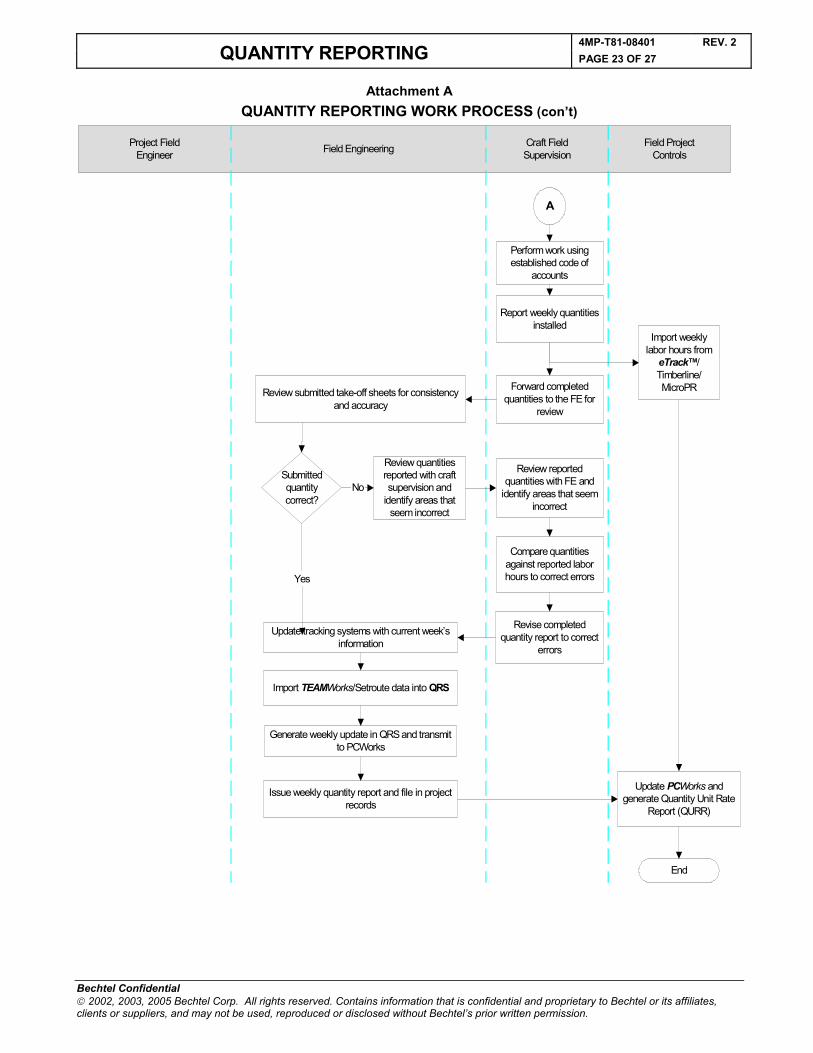
Attachment AQUANTITY REPORTING WORK PROCESS (con’t)
Project FieldEngineer Field Engineering Craft Field
SupervisionField Project
Controls
A
End
Perform work usingestablished code of
accounts
Review quantitiesreported with craftsupervision and
identify areas thatseem incorrect
Review submitted take-off sheets for consistencyand accuracy
Report weekly quantitiesinstalled
Import weeklylabor hours from
eTrack™/Timberline/MicroPRForward completed
quantities to the FE forreview
Submittedquantitycorrect?
Review reportedquantities with FE and
identify areas that seemincorrect
Compare quantitiesagainst reported laborhours to correct errors
Revise completedquantity report to correct
errors
Update tracking systems with current week’sinformation
Import TEAMWorks/Setroute data into QRS
Generate weekly update in QRS and transmitto PCWorks
Issue weekly quantity report and file in projectrecords
Update PCWorks andgenerate Quantity Unit Rate
Report (QURR)
No
Yes

4MP-T81-08401 REV. 2QUANTITY REPORTING PAGE 24 OF 27
Bechtel Confidential 2001,2003, 2005 Bechtel Corp. All rights reserved. Contains information that is confidential and proprietary to Bechtel or its affiliates, clients or suppliers, and may not to be used, reproduced or disclosed without Bechtel’s prior written permission.
Attachment BSAMPLE QUANTITY REPORTING RESPONSIBILITY MATRIX
RESPONSIBILITYSITE
MANAGEMENTFIELD
ENGINEERINGFIELD
SUPERVISIONFIELD
PROJECTCONTROLS
Develop quantity reporting plan S R S S
Identify quantity scope prepare take-offs R
Identify quantity changes resulting from drawing revisions and field changes
R
Report quantities R S
Update and issue project quantity unit rate report S S R
Perform periodic audits to assure reporting accuracy
S S R
Assure system effectiveness, reasonableness, and accuracy
R S
Assures systems adherence R S
Maintain system R S
R = PRIMARY RESPONSIBILITY S = SUPPORT ROLE
4MP-T81-08401 REV. 2QUANTITY REPORTING PAGE 25 OF 27
Bechtel Confidential 2002, 2003, 2005 Bechtel Corp. All rights reserved. Contains information that is confidential and proprietary to Bechtel or its affiliates, clients or suppliers, and may not be used, reproduced or disclosed without Bechtel’s prior written permission.
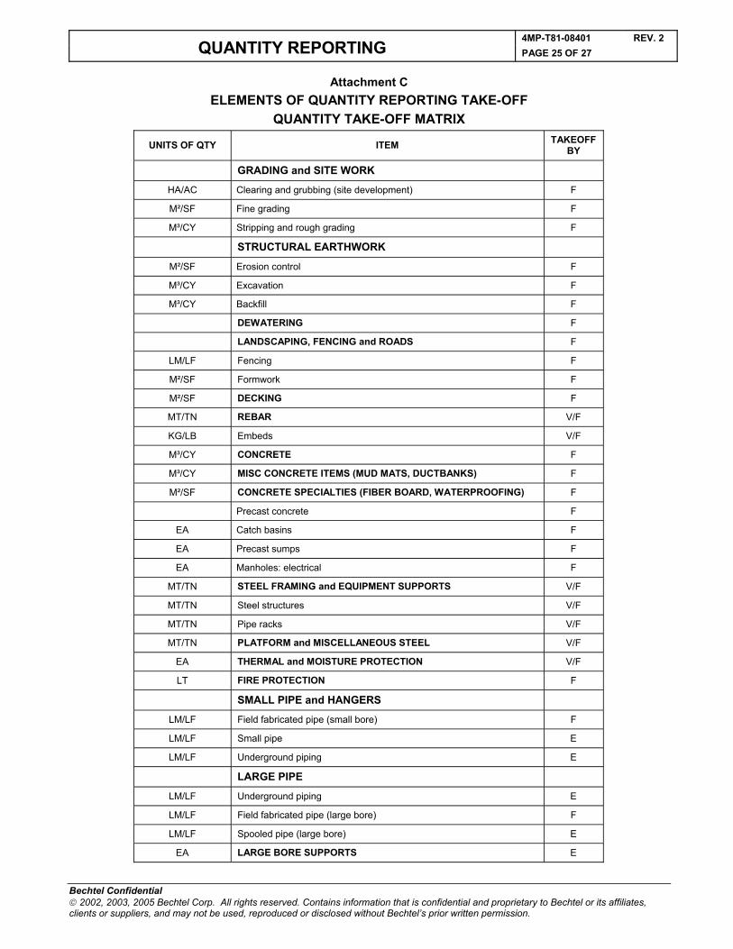
Attachment CELEMENTS OF QUANTITY REPORTING TAKE-OFF
QUANTITY TAKE-OFF MATRIX
UNITS OF QTY ITEM TAKEOFF BY
GRADING and SITE WORK
HA/AC Clearing and grubbing (site development) F
M²/SF Fine grading F
M³/CY Stripping and rough grading F
STRUCTURAL EARTHWORK
M²/SF Erosion control F
M³/CY Excavation F
M³/CY Backfill F
DEWATERING F
LANDSCAPING, FENCING and ROADS F
LM/LF Fencing F
M²/SF Formwork F
M²/SF DECKING F
MT/TN REBAR V/F
KG/LB Embeds V/F
M³/CY CONCRETE F
M³/CY MISC CONCRETE ITEMS (MUD MATS, DUCTBANKS) F
M²/SF CONCRETE SPECIALTIES (FIBER BOARD, WATERPROOFING) F
Precast concrete F
EA Catch basins F
EA Precast sumps F
EA Manholes: electrical F
MT/TN STEEL FRAMING and EQUIPMENT SUPPORTS V/F
MT/TN Steel structures V/F
MT/TN Pipe racks V/F
MT/TN PLATFORM and MISCELLANEOUS STEEL V/F
EA THERMAL and MOISTURE PROTECTION V/F
LT FIRE PROTECTION F
SMALL PIPE and HANGERS
LM/LF Field fabricated pipe (small bore) F
LM/LF Small pipe E
LM/LF Underground piping E
LARGE PIPE
LM/LF Underground piping E
LM/LF Field fabricated pipe (large bore) F
LM/LF Spooled pipe (large bore) E
EA LARGE BORE SUPPORTS E
4MP-T81-08401 REV. 2QUANTITY REPORTING PAGE 26 OF 27
Bechtel Confidential 2002, 2003, 2005 Bechtel Corp. All rights reserved. Contains information that is confidential and proprietary to Bechtel or its affiliates, clients or suppliers, and may not be used, reproduced or disclosed without Bechtel’s prior written permission.
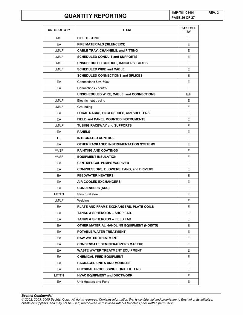
UNITS OF QTY ITEM TAKEOFF BY
LM/LF PIPE TESTING F
EA PIPE MATERIALS (SILENCERS) E
LM/LF CABLE TRAY, CHANNELS, and FITTING E
LM/LF SCHEDULED CONDUIT and SUPPORTS E
LM/LF UNSCHEDULED CONDUIT, HANGERS, BOXES F
LM/LF SCHEDULED WIRE and CABLE E
SCHEDULED CONNECTIONS and SPLICES E
EA Connections 5kv, 600v E
EA Connections - control F
UNSCHEDULED WIRE, CABLE, and CONNECTIONS E/F
LM/LF Electric heat tracing E
LM/LF Grounding F
EA LOCAL RACKS, ENCLOSURES, and SHELTERS E
EA FIELD and PANEL MOUNTED INSTRUMENTS E
LM/LF TUBING RACEWAY and SUPPORTS F
EA PANELS E
LT INTEGRATED CONTROL E
EA OTHER PACKAGED INSTRUMENTATION SYSTEMS E
M²/SF PAINTING AND COATINGS F
M²/SF EQUIPMENT INSULATION F
EA CENTRIFUGAL PUMPS W/DRIVER E
EA COMPRESSORS, BLOWERS, FANS, and DRIVERS E
EA FEEDWATER HEATERS E
EA AIR COOLED EXCHANGERS E
EA CONDENSERS (ACC) E
MT/TN Structural steel F
LM/LF Welding F
EA PLATE AND FRAME EXCHANGERS, PLATE COILS E
EA TANKS & SPHEROIDS – SHOP FAB. E
EA TANKS & SPHEROIDS – FIELD FAB E
EA OTHER MATERIAL HANDLING EQUIPMENT (HOISTS) E
EA POTABLE WATER TREATMENT E
EA RAW WATER TREATMENT E
EA CONDENSATE DEMINERALIZERS MAKEUP E
EA WASTE WATER TREATMENT EQUIPMENT E
EA CHEMICAL FEED EQUIPMENT E
EA PACKAGED UNITS AND MODULES E
EA PHYSICAL PROCESSING EQMT. FILTERS E
MT/TN HVAC EQUIPMENT and DUCTWORK F
EA Unit Heaters and Fans E
4MP-T81-08401 REV. 2QUANTITY REPORTING PAGE 27 OF 27
Bechtel Confidential 2002, 2003, 2005 Bechtel Corp. All rights reserved. Contains information that is confidential and proprietary to Bechtel or its affiliates, clients or suppliers, and may not be used, reproduced or disclosed without Bechtel’s prior written permission.
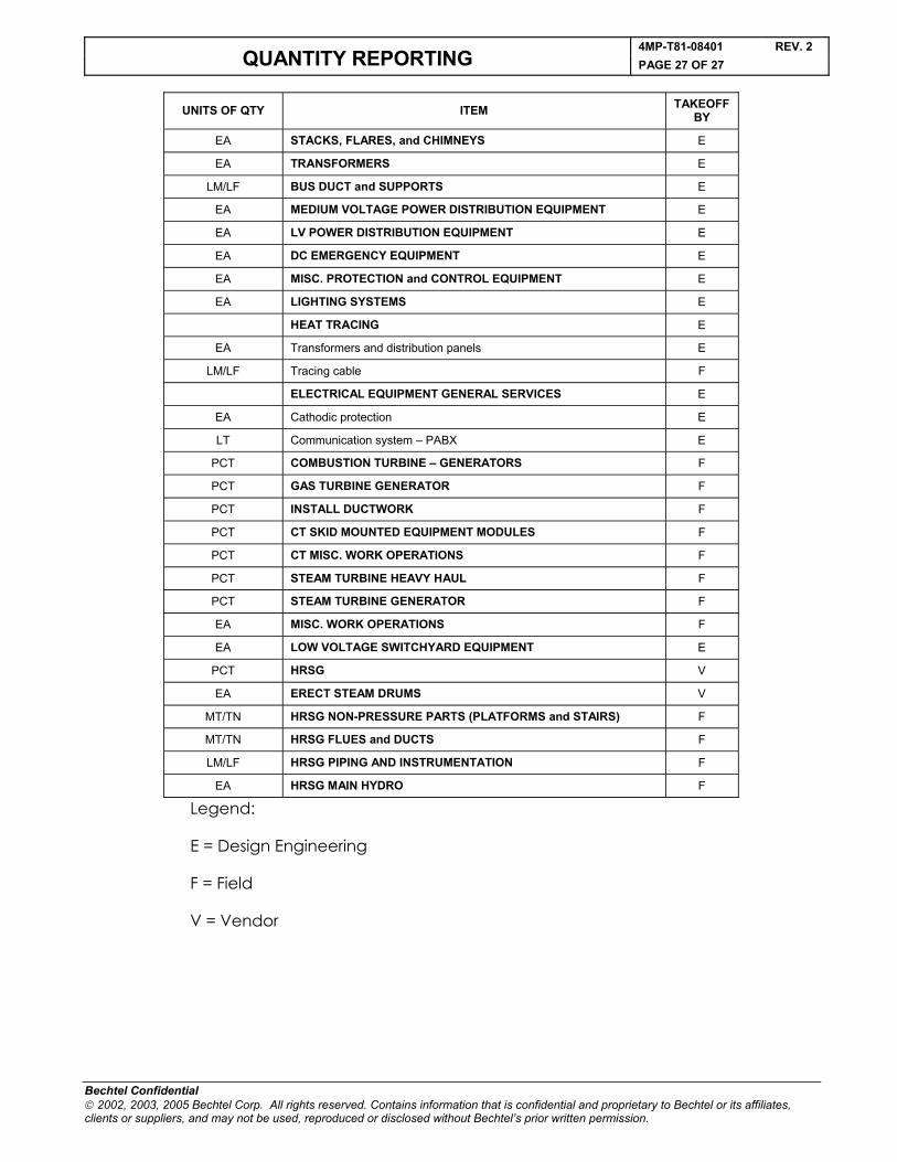
UNITS OF QTY ITEM TAKEOFF BY
EA STACKS, FLARES, and CHIMNEYS E
EA TRANSFORMERS E
LM/LF BUS DUCT and SUPPORTS E
EA MEDIUM VOLTAGE POWER DISTRIBUTION EQUIPMENT E
EA LV POWER DISTRIBUTION EQUIPMENT E
EA DC EMERGENCY EQUIPMENT E
EA MISC. PROTECTION and CONTROL EQUIPMENT E
EA LIGHTING SYSTEMS E
HEAT TRACING E
EA Transformers and distribution panels E
LM/LF Tracing cable F
ELECTRICAL EQUIPMENT GENERAL SERVICES E
EA Cathodic protection E
LT Communication system – PABX E
PCT COMBUSTION TURBINE – GENERATORS F
PCT GAS TURBINE GENERATOR F
PCT INSTALL DUCTWORK F
PCT CT SKID MOUNTED EQUIPMENT MODULES F
PCT CT MISC. WORK OPERATIONS F
PCT STEAM TURBINE HEAVY HAUL F
PCT STEAM TURBINE GENERATOR F
EA MISC. WORK OPERATIONS F
EA LOW VOLTAGE SWITCHYARD EQUIPMENT E
PCT HRSG V
EA ERECT STEAM DRUMS V
MT/TN HRSG NON-PRESSURE PARTS (PLATFORMS and STAIRS) F
MT/TN HRSG FLUES and DUCTS F
LM/LF HRSG PIPING AND INSTRUMENTATION F
EA HRSG MAIN HYDRO F
Legend:
E = Design Engineering
F = Field
V = Vendor