Embed Size (px)
Citation preview

Research ArticleQuantitative Comparison of the Efficiency and Scalability ofthe Current and Future LTE Network Architectures
Morteza Karimzadeh1 Hans van den Berg12 Ricardo de O Schmidt13 and Aiko Pras1
1Design and Analysis of Communication Systems (DACS) University of Twente Enschede Netherlands2Netherlands Organization for Applied Scientific Research (TNO) The Hague Netherlands3SIDN Labs Arnhem Netherlands
Correspondence should be addressed to Morteza Karimzadeh mrkarimzadehgmailcom
Received 2 June 2017 Accepted 12 September 2017 Published 5 November 2017
Academic Editor Luca Foschini
Copyright copy 2017 Morteza Karimzadeh et al This is an open access article distributed under the Creative Commons AttributionLicense which permits unrestricted use distribution and reproduction in any medium provided the original work is properlycited
The core architecture of current mobile networks does not scale well to cope with future traffic demands owing to its highlycentralized composition Typically it is believed that decentralization of the network architecture would be a sustainable approachto deal with ever growing amount of mobile data traffic Nevertheless the decentralization strategy of network architecture hasnot been properly examined through quantitative performance studies Given that LTE will be the leading mobile networkingtechnology in the coming 5ndash10 years we conduct a hybrid study model to compare performance of current and future(decentralized) LTE network architectures Particularly our analysis presents numerical results quantifying impact of the numberof attached nodes on the load at network routers and links on the latency and on the processing cost of the userrsquos data and controlplanes Analytical results demonstrate that decentralization of the LTEnetwork architecture achieves higher performance comparedto the current architecture and improves the latency and cost of data packet delivery more than 10 and 6 times respectivelyFurthermore it is also observed that GTP outperforms PMIP for all studied performance metrics in the decentralized architectureand provides about twofold better latency and cost for data packet delivery and roughly 6 times lower data traffic load on thenetwork routers
1 Introduction
Over the last years with the ubiquitous deployment and rapidevolution of mobile networks (eg 3GPP and WiMAX) thedemand of accessing the Internet for mobile users has beensoared dramatically The mobile devices (eg smart-phonesand tablets) become an integral part of everyonersquos daily liveand generate a substantial part of the total Internet trafficwhich is still increasing significantly
It is forecasted that by 2021 there will be around 12billion mobile devices worldwide and 82 from these willbe smart mobile devices generating up to 99 of all mobiledata Overall mobile data is expected to increase from 7EBper month seen in 2016 to 49 EB per month in 2021 [1 2]Copingwith such a demand in the currentmobile networks isneither economically nor technically viableTheRadioAccessNetwork (RAN) cannot be easily extended due to spectrumlimitations Furthermore the core of mobile networks is
highly centralized which introduces scalability and reliabilityproblems
Mobile network operators increase RAN capacity byimproving spectrum utilization in several ways for exam-ple deployment of small cells selectively offloading trafficfrom cellular access to WiFi technology and exploitingmulticarrier techniques or multiple radio access technologyapproaches [3 4] The major challenge regarding the corenetworks (standardized by 3GPP IETF) is related to thefact that a few high level network entities entitled anchorpoints manage both the data plane and the control planeIn such a centralized architecture mobile nodersquos (MNrsquos)traffic must traverse the core anchor point and then go tothe corresponding service node (CN) see Figure 1(a) Thismakes the network prone to several limitations for examplesuboptimal routing low scalability signaling overhead andthe lack of granularity on services [5 6]
HindawiWireless Communications and Mobile ComputingVolume 2017 Article ID 3938545 20 pageshttpsdoiorg10115520173938545
2 Wireless Communications and Mobile Computing
CNCN
Anchor point
Access gateway
(a)
CNCN
Anchor point
Access gatewayDecentralization of core network entities
(b)
Figure 1 A general view of the current (centralized) (a) and future (decentralized) (b) mobile network architectures
S1-MME
eNodeB-1
UE
X2-U
S1-U
eNodeB-2
Mov
emen
t
MME
S11
SGWS5S8
Gx
PGWSGi Internet
PCRF
GTPOver G
TP-CGTP-U
GTPOver GTP-CGTP-U
PMIPOver GRE
Figure 2 Current LTE architecture and its two mobility management protocols for 3GPP access
The straightforward solution to cope with such an issuemay consist of operators investment to upgrade the resourcesof the core network entities Although this approach istechnically feasible network operators always prefer cost-effective and more sustainable solutions Traffic offloadingis an alternative approach to effectively reduce the traffictraversing through core network entities and to mitigate thetraffic overhead on the limited resources of the core partThis can be achieved by placing small-scale anchor points inthe proximity of the access network to locally handle MNsconnections and traffic [7] This essentially leads to a decen-tralized (flat) network architecture see Figure 1(b) Eventhough decentralization also requires further investments fornetwork architecture changes and management it seems inthe long term to be more cost-efficient than continuouslyextending capacity of the centralized architecture to copewith the future demands
Long-Term Evolution (LTE) is expected to be the leadingmobile networking technology in the next decade handlingsubstantial part of ever growing globalmobile data traffic It is
predicted that the development of LTE will not keep up withthe growth ofmobile traffic andwhile it supports almost 69(out of 7 EB) of the current mobile traffic it is estimated tohandle about 79 (out of 49 EB) of theworldwidemobile datatraffic by 2021 [1 2]
Therefore in this paper we pay special attention tothe LTE system and perform a hybrid study includingsimulation and analytical models to analyze in detail theperformance and scalability of the current and a decen-tralized LTE network architecture In particular we analyt-ically evaluate both network architectures to quantify howmuch the load on network resources (routers and links)and the latency and cost of the userrsquos data plane (trafficforwarding procedures) and control plane (attachment andhandover procedures) are affected by the increasing numberof attached mobile nodes We analyze performance of GPRSTunneling Protocol (GTP) and Proxy Mobile IP protocol(PMIP) the two commonly used protocols in the LTE systemto handle MNs data traffic and mobility in 3GPP access(Figure 2)
Wireless Communications and Mobile Computing 3
Summarizing ourmain contributions in this paper are asfollows
(i) Develop a detailed model of the functions of GTPand PMIP protocols for 3GPP access on both current(centralized) and future (decentralized) LTE networkarchitectures
(ii) Carry out a hybrid study combining simulation andanalytical modeling capturing the most essentialcharacteristics of the system while abstracting fromthe less important details in order to evaluate variousscenarios in feasible time
(iii) Using the developed approach derive variousmetricsto quantify and analyze the performance and scalabil-ity of the LTE network system (current architectureversus decentralized architecture)
(iv) Relying on the obtained numerical results providean intuition of the expected impact of the numberof subscribers on the different LTE core networkarchitectures
The rest of this paper is organized as follows Section 2provides concisely the necessary background about the cur-rent LTE and its existing mobility management solutionsfor 3GPP access Section 3 discusses our hybrid modelingstudy Section 4 describes in detail the analytical calculationof the performance metrics and the evaluation procedureThe results to compare the performance and scalability ofdifferent network architectures are presented in Section 5Section 6 reviews in brief the recent related works andspecifies how our work differs from the literature Finally thepaper ends up with the conclusion and discussion parts inSections 7 and 8 respectively
2 LTE Architecture
This section gives a brief overview for current LTE networkarchitecture and the two existing mobility managementprotocols for 3GPP access which are essential for perceivingthe problem statement as well as the proposed model in thiswork
The LTE architecture is hierarchical and defines theEvolved Packet System (EPS) consisting of Evolved UniversalTerrestrial Radio Access Network (E-UTRAN) and EvolvedPacket Core (EPC) The E-UTRAN consists of a network ofradio base stations (eNodeBmdashevolved Node B) that provideradio connectivity to User Equipment (UE) The EPC is amultiaccess IP-based network that allows for a common corenetwork for 3GPP and non-3GPP radio access and fixedaccess
The EPC consists of four main elements (Figure 2) thatallow for the convergence of packet-based services [10]
(i) ServingGateway (SGW) is a user plane node that pro-vides data paths and routes traffic between eNodeBsand PGW It also acts as a local mobility anchor forUEs performing handover between eNodeBs
(ii) PDN Gateway (PGW) provides the connectionbetween the EPC and other external IP networks as
well as several additional functions such as IP addressanchoring and allocation routing packet filteringand monitoring and policy control
(iii) Mobility Management Entity (MME) whose keyrole is to handle UE mobility also performs thecontrol functions to access the LTE assigns networkresources and supports roaming and handover pro-cedure
(iv) Policy and Charging Rule Function (PCRF) dynam-ically controls and manages all data sessions anddetermines quality of service (QoS) policies andcharging rules to SGW and PGW
21 Mobility Management Protocols Current EPC may useGTP or PMIP protocol to support UErsquos mobility for 3GPPaccess networks [11] These protocols allow an uninterruptedhandover for the UEs during internetwork mobility Tomanage UErsquos mobility using GTP or PMIP the PGW mightconnect to SGW via S5S8 interfaces (Figure 2) for nonroam-ing and roaming scenarios respectively [11]
The GTP protocol is able to fully handle the control anddata planes It can forward the UErsquos downlink packets fromsource location to target place during handover The PMIPhowever can only handle UErsquos mobility and perform dataforwarding after handover procedure Moreover it is not ableto control the bearers andQoS signalingWhen PMIP is usedover the S5S8 interface the GTP bearers are only definedbetween UE and the SGW In this case the SGW takes overthe bearer binding operations and an additional connection(dash line in Figure 2) needs to be created between the SGWand the PCRF to provide the required information on QoSpolicy [9 10 12]
UEmay perform a handover in either idle or activemodeIn idle mode the UE stays in power consumption mode anddoes not inform the network about the location informationThe network uses the tracking and paging procedures todiscover position of UE In active mode UErsquos mobility iscompletely under control of the network The decision toperform a handover and to choose the target cell is handledby the network based on measurements performed by theeNodeB and the UE During the handover procedure GTPcan locate theUErsquos position even in the idlemode to establishthe required data and control planes tunnels However PMIPdoes not support tracking and paging functions and theUE needs to be always in active mode Therefore GTPprotocol is mostly used in the access network between SGWand eNodeBs to eliminate the aforementioned drawbacks ofPMIP
The decision for using GTP or PMIP over the S5S8interface depends on several parameters such as technicalsupport and existence of roaming scenarios among the 3GPPaccess and non-3GPP access networks Note also that mobil-ity management protocols for non-3GPP such as Mobile IP(MIP) andDual StackMIP (DSMIP) [10] are out of the scopeof this study
22 Data andControl Planes Tunneling WhenUE attaches tothe LTE network several control messages are exchanged
4 Wireless Communications and Mobile Computing
UE
MME
PCRF
PGW
GRE
SGW
S1-MME
GTP
-C
eNodeB-1
eNodeB-2
GREIPv6
S1-U
PMIPv6 GTP
UDP GTP-U
S5S8
GTP-U
GTP-C
GIP-U
Mov
emen
t
S11
(40 B)IPv6
(40 B) (16 B)(8 B)
UDP GTP-CIPv6(40 B) (12 B)(8 B)
(24 B)
InternetSGi
Gx
X2-U
GTP
-UControlmessage
User datapacket
Control messageuser data packet
(a) GTP and PMIP headers
MME
PGWSGW-1
SGW-2
eNodeB-1
eNodeB-2
Mov
emen
t
Internet
Control tunnelrelocation
Data amp controltunnel relocation
UE
(b) Tunnel updating during handover
Figure 3 LTE data and control planes for 3GPP access
between the eNodeB MME SGW and PGW Using GTPprotocol a successful attachment results in a tunnel for theuser data plane (GTP-U) between the eNodeB and SGW andbetween the SGW and PGW Another tunnel for the controlplane (GTP-C) is established between the SGW and PGWand also between the MME and SGW (Figure 3(a)) WhileGTP-U simply transports data packets within the core andradio access networks GTP-C tunnel is used to exchange thecontrol messages for handling UErsquos mobility as well as forpath management and tunnel management (eg adjustingQoS parameters updating sessions for roaming subscribersand activating and deactivating subscriber sessions) Thesetunnels are created for each individual UE traffic flow (IPtraffic) Each GTP tunnel has an identifier entitled TunnelEnd Point Identifier (TEID) Based on the TEID the networkis able to choose the appropriate tunnels to transfer datapackets and control messages between the end points
In the case of PMIP protocol basic IP connectivity overGeneric Routing Encapsulation (GRE) tunneling is usedbetween the SGWandPGW and aGREkey is used to identifyeach tunnel
As Figure 3(b) shows during a handover between neigh-boring eNodeBs the GTP-U tunnel is updated and if thehandover is between neighboring SGWs both GTP-U andGTP-C (or GRE) are updated
Note that tunneled packetsmight be further encapsulatedby IPsec protocol in order to protect both control messagesand data In this study we only focus on the data and con-trol planesrsquo tunnels established over the transport networkAdditional control signaling involved on UErsquos attachmenthandover and data delivery procedures with the otherLTE components as well as IPsec is out of scope in thispaper
23 Mobility Management Messages The signaling for UEmobility control is similar for GTP and PMIP in the accessnetwork (Figure 2) Differences depend on the mobilityprotocol in the core network over the S5S8 interfaces
Figure 4 shows the GTP and PMIP mobility messagesin the core network during UE attachment and handoverprocedures
Wireless Communications and Mobile Computing 5
SGW-1
SGW-2
S5S8
Create Session Req amp Res
Modify Bearer Req amp Res
Modify Bearer Req amp Res
Modify BearerReq amp ResH
ando
ver p
roce
dure
Han
dove
r pro
cedu
reSG
W re
loca
tion
eNod
B re
loca
tion
PGW
Atta
chm
ent
proc
edur
e
GTP-C
(a) GTP-based
SGW-2
SGW-1 PGW
Han
dove
r pro
cedu
re
Han
dove
r pro
cedu
reSG
W re
loca
tion
eNod
B re
loca
tion
Atta
chm
ent
proc
edur
e
PCRFS5S8PMIP
Gateway Control Session Req amp Res
Gateway Control Session Req amp Res
Gateway Control Session
Req amp ResProxy Binding
Upd amp Ack
Proxy Binding Upd amp Ack
(b) PMIP-based
Figure 4 UE attachment and handover procedures messages
Table 1 Mobility messages for GTP [8]
Message Size HeadersCreate Session Request (CSReq) 335 B 60 BCreate Session Response (CSRes) 224 B 60 BModify Bearer Request (MBReq) 67 B 60 BModify Bearer Response (MBRes) 81 B 60 B
231 For the GTP Protocol Table 1 lists the messages usedin the procedures described in the following as well astheir respective sizes Note that the size information doesnot include the extra GTP-C tunnel header size which ispresented in a separated column
For GTP protocol when UErsquos switch is turned on anAttach Request message is sent to the MME through theeNodeBTheMME then sends aCSReqmessage to the SGWwhich is forwarded to the PGW This request is meant forsetting up the UErsquos default bearer and also for requestinga Packet Data Network (PDN) connectivity The reply fromthe PGW containing an IP address for the UE and a defaultbearer ID is also forwarded by the SGW to the eNodeB andthe MME With this information the attachment procedureis concluded and the traffic from the UE can flow from theeNodeB to the SGW via the S1-U interface (Figure 3(a)) TheMME still sends a MBReq message to the SGW which inturn is forwarded to the PGW containing the TEID assignedto the eNodeB The PGW finally replies to this request witha MBRes message and the user data plane is then set up fortraffic flow in the core network
During a handover between eNodeBs the target eNodeBsends a Path Switch Request to the MME informing thatthe UE has changed its physical location The MME thensends to the SGW aMBReq message with the address of thenew eNodeB and the TEID of the user plane for downlinkThis information is forwarded by the SGW to the PGW ThePGW replies with a MBRes message to the SGW that starts
Table 2 Mobility messages for PMIP [9]
Message Size HeadersGateway Control Session Request (GCSReq) 336 B 68 BGateway Control Session Response (GCSRes) 972 B 68 BProxy Binding Update (PBU) 104 B 64 BProxy Binding Acknowledge (PBA) 104 B 64 B
forwarding downlink packets to the target eNodeB (currentUE location)
On realizing that the SGW has been relocated (from thePath Switch Request message sent by the target eNodeB)the MME sends a CSReq message to the target SGW Thismessage contains the PGW addresses the TEIDs used foruplink traffic the address of the target eNodeB and theprotocol type used over S5 or S8 interface The target SGWassigns the addresses and TEIDs for downlink traffic from thePGW and sends a MBReq message to the PGW informingabout the changes The PGW then updates its context fieldand replies to the SGWwith a MBRes message including itsaddress and TEIDs information [11]
232 For the PMIP Protocol Table 2 lists the messages usedin the procedures explained in this section as well as theirrespective sizes Note that the size information does notinclude additional header sizes which can differ and arepresented in a separated column
For PMIP the initial attachment procedure of UE issimilar to that of the GTP The only difference is that theSGW has to establish a control session towards the PCRF toobtain the QoS policy information needed to perform thebearer binding All these are obtained through a GCSResmessage sent by the PCRF to the SGW in reply to a GCSReqmessage This message exchange is done over the StreamControl Transmission Protocol (SCTP)
To establish the default bearers the SGW sends to thePGWaPBUmessage containing amongothers theGREkey
6 Wireless Communications and Mobile Computing
Networktopology model
Mobility modelTraffic model
Delay model Performance metricscalculation
Analytical modelSimulation model
Figure 5 The hybrid modeling study
for downlink traffic address information of the UE to requestan IPv6 prefix and charging characteristicsThe PGW repliesto the SGW with a PBA message containing among othersthe UErsquos address the GRE key for uplink traffic and thecharging ID These two messages are exchanged over a GREtunnel and after this exchange the SGW and the PGW setup an additional bidirectional GRE tunnel for forwarding ofUErsquos data flows
During handover between eNodeBs the SGW sends tothe PCRF aGCSReqmessage informing about the change ofUErsquos location which was received from the MMEThe PCRFreplies to the SGW with a GCSRes message providingamong others the updated QoS policy and charging rules Incase of a handover with SGW relocation in addition to thePCRF messages the new SGW have to exchange the PBUand PBA messages with the PGW [10]
In the following Section 3 describes our hybridmodelingapproach to quantify the gains on performance and scalabilityin four different scenarios the current (centralized) and adecentralized EPC architecture with GTP and PMIPmobilitymanagement protocols Next in Section 4 we present thecalculation of various performance metrics in detail
3 Hybrid Simulation and Analytical Modeling
This section describes our hybrid study containing simulationand analytical modeling As described in the Introductionthe simulation model captures the dynamic behaviour ofthe system at mobile node and connection level deliveringinformation about for example link load and load of routersin the different network layers This information togetherwith other network and traffic parameters is used in theanalytical delay model to derive queuing delay for datapacket and control messages processing in the nodes as wellas queuing delays for transmitting this information on thenetwork links Eventually these intermediate results are usedto calculate end-to-end data packet delivery delay and costcontrol plane and data plane loads
Figure 5 shows schematically how the various parts of ourhybrid model relate to each other
CN3
CN1
CN2
R9R8R7R6 R10
R5R4R3R2
R11
R1 Core layer
Distribution layer
Access layer
E2E traffic path in the decentralized approachE2E traffic path in the centralized approach
Centralized approachDecentralized approach
R1 function R2ndashR5 function
Router RouterRouterPGW
R6ndashR1 function
SPGWSGW
Figure 6 The network topology used in the analytical model
It is important to remark that in our approach onone hand we capture the most essential characteristics ofthe system and on the other hand abstract from the lessimportant details to set up an straightforward environmentto perform the modeling and analyses in a feasible time Weuse MATLAB as the environment to implement the modelsand perform the analysis Using a normal desktop computerit takes only a couple of minutes to carry out the completetasks for all scenarios
Table 3 presents the notation used in the hybrid modelas well as in the analytical calculation to compute differentperformance metrics (Section 4)
31 Network Topology Model Figure 6 shows the networktopology used in our modeling This topology follows theCisco 3-layer hierarchical model consisting of the coredistribution and access layers The core layer handles traffictransferred to and from the routers at the distribution layerThe distribution layer enables the communication betweenrouters from the core and access layers The access layermainly controls the attachment of end users and devices tothe network
We define two network scenarios in our models thecurrent (centralized) and future (decentralized) networkarchitectures in context of the LTE system In each of thesethe routers in the core and the access layers play differentroles
In the first scenario for the centralized architecture thePGW is placed in the top of the topology (R1 in Figure 6)and the SGWs are placed at the edge routers (R6 to R11) Inthis scenario the PGW is the anchoring point of the networkand handles all data and control plane operationsThe SGWsprovide the data paths towards the core and routeUE packetsbetween the access network and the PGW
In the second scenario for the decentralized architecturewe define SPGWs which are physical nodes combiningfunctions of the SGW and PGW elements In this scenariothe SPGWs operate as the distributed anchoring points andhandle the data and control plane operations locallyThese are
Wireless Communications and Mobile Computing 7
Table 3 The notations used in the hybrid model and analytical calculation
Symbol Definition Value퐻푥-푦 Number of hops between arbitrary nodes 푥 and 푦푑(푥)119897 Queuing delay of 푥 in the network link 푙 due to traffic load 푥 isin 푝 (푝 + 푡푢) (푚 + 푡푐)훿(푥)119897 Transmission delay of 푥 in the network link 푙 푥 isin 푝 (푝 + 푡푢) (푚 + 푡푐)휏푝(119901119898)119895 Packet (푝) or message (푚) processing delay in router 푗휏푟(119901119898)119895 푝 or푚 routing delay in router 푗휏푡(119901119898)119909 푝 or푚 tunneling delay in the node 푥 푥 isin SGWPGW SPGW푑(푝푚)119895 푝 or푚 queuing delay in router 푗 due to processing load푁ℎ119894 Number of handovers (ℎ) for node 푖 during simulation time푁푘119894 Number of paths (푘) created for node 푖 due to mobilityMNAP(푥) Messages number of initial attachment procedure 푥 isin GTPPMIPMNHP(푥) Messages number of handover procedure 푥 isin GTPPMIPALDPD푖 Average latency of packet delivery for node 푖ACDPD푖 Average processing cost of packet delivery for node 푖LDPD푘 Latency of packet delivery in path 푘CDPD푘 Processing cost of packet delivery in path 푘LAP푖 Latency of attachment procedure for node 푖CAP푖 Processing cost of attachment procedure for node 푖LHP푖 Latency of handover procedure for node 푖CHP푖 Processing cost of handover procedure for node 푖CML(푁)119895 Control message lode (number) over router 푗 during simulation timeCML(KBs)119895 Control message load (size) over router 푗 during simulation time
placed in the access layer (R6 to R11) Herein the core router(R1) is only used when data has to be routed through it
In both scenarios routers on the distribution layer per-form as normal L3 routers and enable the communicationbetween the core and access layers
We consider three static CNs located at each layer Theserepresent the data centers that in reality could be geograph-ically distributed The data traffic to UE is transmitted withthe shortest path through (CN rarr PGW rarr SGW rarr UE) or(CNrarr SPGWrarr UE) for the centralized and decentralizedscenarios respectively It is important to mention that weignore all the detailed functions of the routing mechanism(eg load balancing) in our model As in this paper weperform a comparative analysis for the different networkarchitectures using a plain routing solution having no severeeffect on the final outcome of the comparison
The two network architecture scenarios described aboveare later (in Section 4) combined with both the GTP andPMIP protocols to define the four scenarios being analyzedin this work
32 Mobility Model A straightforward approach to modelmobility is by obtaining the time spent by amobile node (alsoknown as the residence timeor the dwell time) in each SGW(orSPGW) during movement The Fluid-Flow mobility modelis a simple approach to drive the mobile nodersquos dwell timein cellular networks which has been extensively used inprevious work [13ndash16] By applying the Fluid-Flow model
where 퐸(V) is the average speed of a mobile node the averagedwell time of the node in each SGW is given by
퐸 [푇dwell] = 휋 times 퐴퐸 (V) times 푃 = 휋 times (휋푅2)
퐸 (V) times (2휋푅) =휋푅
2퐸 (V) (1)
where 푅 퐴 and 푃 denote the radius coverage area andperimeter of each SGW respectively Note that for eachmobile node 퐸(V) is arbitrarily chosen from the predefinedvalues listed in Table 5
We assume that a mobile node randomly attaches to oneof the SGWs and after passing the dwell time it starts to movetowards the neighbor SGW This movement is modeled byrandomly choosing one of the neighbor SGWs and staying init for the dwell timeThis procedure is continuously repeatedduring the simulation time Therefore the number of han-dovers for eachmobile node (푁ℎ119894) can be easily derived usingits dwell time and the simulation time For both scenariosmobile nodes choose the same trajectories affecting the pathscreated for the related control and data planes during thesimulation time In our model we assume that 퐸(V) for eachmobile node is constant during the simulation time It is alsoassumed that each SGW covers a circular domain consistingof three eNodeBs and therefore for a SGW relocation therewill be three handovers between neighboring eNodeBs
33 Traffic Model We assume that each mobile node ran-domly attaches to one of the SGWs (or SPGWs) and starts todownload data from one of the CNs also randomly chosen
8 Wireless Communications and Mobile Computing
Every mobile node has a single active session to one of theCNs during the whole simulation time Every node followsthemobilitymodel described in the previous section and afterstaying at each access layer entity (SGWs or SPGWs) for itsdwell time moves to one of the neighboring entities
A Poisson traffic stream with average rate of 100 packetsper second (CNTR) is generated from the CNs towards theconnected mobile nodes simulating the download of databy the attached nodes For the sake of simplicity this modelignores the packet level details (eg packet loss and lossrecovery mechanism) To avoid IP packet fragmentation asa result of tunneling overhead at the core network we setthe size of packets from the CNs to 1200 Bytes ([17] advisesa default MTU size of 1280 Bytes)
34 Delay Model During a transmission between two end-points data packets or control messages may be delayed dueto for example link congestion and queues In our modelthe network link delay in each hop includes the transmissiondelay (훿(푥)119897) and the queuing delay (푑(푥)119897) where 푥 is either apure or a tunneled data packet or control message (Table 3)Applying an MM1 queuing model the average delay (푇(푝)119897)of a data packet of size 푝 transmitted in the network link 푙with transmission rate TR and traffic load CNTR per mobilenode is given by
푇(푝)119897 = [훿(푝)119897 + 푑(푝)119897] =훿(푝)119897
1 minus 퐿 (푝)119897 퐿 (푝)119897 =
휆푙 times 푝TR
(2)
휆푙 denotes the network link traffic derived from thesimulation by keeping track of all paths that are establishedusing link 푙 as well as their duration and taking into accountthe packet rate
For a data packet 푝 or a control message푚 and a node 푗the router delay consists of the processing delay (휏푝(119901119898)119895 ) thedata packet encapsulationdecapsulation or control messageconstructionextraction delay (휏푡(푝푚)119895) during a tunnelingthe routing delay (휏푟(119901119898)119895 ) and the queuing delay (푑(푝푚)119895) atthe router (Table 3) For matters of simplicity we assume that휏푝(119901119898)119895 = 휏푡(119901119898) = 휏푟(119901119898) Similar to the network link delay fora network router 푗 with the processing rate PR the averagedelay (푇(푝)119895) for a data packet 푝 is defined by
푇(푝)119895 = [휏푝(119901)119895 + 푑(푝)119895] =휏푝(119901)119895
1 minus 퐿 (푝)119895 퐿 (푝)119895 =
휆푗 times 푝PR
(3)
Herein 휆푗 signifies the network router traffic obtainedfrom the simulation by keeping track of all paths that crossedrouter 푗 as well as their duration4 Calculation of the Performance Metrics
This section presents the analytical calculation of the perfor-mancemetrics (Table 4) defined in ourmodel to quantify theimpact of the number of mobile nodes on the performanceof the EPC current and decentralized network architectureswith the GTP and PMIP protocols
Table 4 Performance metrics
Symbol DefinitionALDPD Average latency of data packet deliveryACDPD Average processing cost of data packet deliveryALAP Average latency of initial attachment procedureCAP Processing cost of initial attachment procedureALHP Average latency of handover procedureACHP Average processing cost of handover procedureLR Load of routersLNL Load of network linksCML(푁) Control messages load (number)CML(KBs) Control messages load (size)
In current EPC architecture PGW handles centrally theMNrsquos data traffic and mobility through the whole networkHowever in decentralized architecture the SPGWs beingdistributed closer to edge of the networkmanage traffic of theMNs attached locally and handle theirmobility whenmovingbetween the eNodeBs Therefore an additional mechanismneeds to be implemented on top of the SPGWs to keepongoing traffic sessions active for the MNs performinghandovers with SPGW relocation Different approachesmaydemand additional components and modifications in thenetwork topology as well as impose further signaling effortsin the network which must also be taken into account see[18ndash22] as examples
In our model we only study the parameters related to thecore network That is because the structures and characteris-tics for the access and wireless networks are the same for boththe centralized and decentralized LTE architectures
In the following Section 41 defines the performancemetrics listed in Table 4 Next we detail the latency andprocessing cost related metrics for both architectures inSections 42 and 43 respectively
41 Definition of Performance Metrics
(i)TheAverage Latency of Data Packet Delivery (ALDPD)TheALDPD is obtained using the average latency of data packetdelivery for each mobile node 푖
ALDPD = sum푁node푖=1 ALDPD푖푁node
(4)
The individual ALDPD for a mobile node 푖 is given by
ALDPD푖 = LAP푖 + LHP푖 + LDPD푖 (5)
where
LHP푖 =sum푁ℎ119894ℎ119894=1
LHPℎ119894푁ℎ119894
LDPD푖 =sum푁119896119894푘119894=1
LDPD푘119894푁푘119894
(6)
Wireless Communications and Mobile Computing 9
Table 5 Input parameters (assumptions)
Symbol Definition Value푁node Number of mobile nodes [100 sdot sdot sdot 1000]퐸(V) Average velocity of mobile nodes 25 50 or 75 kmh푅 Radius of the coverage area of the access routers 1200m푝 Average data packet size 1200 BytesCNTR CNs generating traffic (a Poisson traffic stream) With average 100 ppsPR Routers processing rate 1000K ppsTR Network links transmission rate 100K pps퐶PGW Cost of processing 퐶푝 routing 퐶푟 or tunneling 퐶푡 at PGW 1 unit per KB퐶SGW Cost of processing 퐶푝 routing 퐶푟 or tunneling 퐶푡 at SGW 13 unit per KB퐶푟119895 Cost of routing at the distribution router 푗 14 unit per KB
Note that LAP푖 is the latency of the initial attachmentprocedure for mobile node 푖 The LHP푖 and LDPD푖 definethe average handover latency and the average latency for datapacket delivery over the created paths (due to mobility) formobile node 푖 respectively(ii) Average Processing Cost of Data Packet Delivery (ACDPD)The ACDPD is obtained by
ACDPD =푁node
sum푖=1
ACDPD푖 (7)
The individual ACDPD for a mobile node 푖 is given by
ACDPD푖 = CAP푖 + CHP푖 + CDPD푖 (8)
where
CHP푖 =sum푁ℎ119894ℎ119894=1
CHPℎ119894푁ℎ119894
CDPD푖 =sum푁119896119894푘119894=1
CDPD푘119894푁푘119894
(9)
Herein CAP푖 is the processing cost of the initial attachmentprocedure for the mobile node 푖 The CHP푖 and CDPD푖define the average handover processing cost and the averageprocessing cost for data packet delivery over the created paths(due to mobility) for mobile node 푖 respectively
One may note that LAP푖 and CAP푖 may slightly affectthe overall amount of the ALDPD and ACDPD respectivelyHowever we would like to discuss all parameters involvedduring the data packet delivery procedure to acquire moreprecise results
(iii) Average Latency of Initial Attachment Procedure (ALAP)It is given by
ALAP = sum푁node푖=1 LAP푖푁node
(10)
(iv) Processing Cost of Initial Attachment Procedure (CAP)The CAP is obtained by
CAP =푁node
sum푖=1
CAP푖 (11)
(v) Average Latency for Handover Procedure (ALHP) TheALHP is given by
ALHP = sum푁node푖=1 LHP푖푁node
(12)
(vi) Average Processing Cost for Handover Procedure (ACHP)It is given by
ACHP =푁node
sum푖=1
CHP푖 (13)
(vii) Load of the Network Routers (LR) and Load of theNetwork Links (LNL) The LR and LNL define the data planeloads implying how many times MNs traffic passes throughthe network routers and links respectively
(viii) The Control Message Load in Terms of Number(퐶푀퐿 (푁)) and Size of Messages (CML(퐾퐵푠)) The CML(푁)defines the load of control plane at the network routers interms of the number of messages It is obtained by
CML(푁)119895 =푁node
sum푖=1
(MNAP(GTPPMIP)
+MNHP(GTPPMIP) times 푁ℎ119894) (14)
We count the CML(푁) for both EPC network architecturesusing the GTP and PMIP protocols
The CML(KBs) is another interpretation of CML(푁) thattakes into account also the size of messages and representsa better view of control plane related load at the networkrouters Considering that the control messages type and size
10 Wireless Communications and Mobile Computing
for the GTP and PMIP protocols are different making theexpression of CML(KBs) more complex we avoid to present ithere
In the following we elaborate on the ALDPD푖 andACDPD푖 covering also the latency of the initial attachment(LAP푖) and the average handover (LHP푖) procedures aswell as the related costs (CAP푖 and CHP푖) respectivelyAbbreviations of the control messages used in the followingsections are listed in Tables 1 and 2 Moreover the notationsfor the elements used in the analytical calculation of theperformancemetrics as well as the input parameters are listedin Tables 3 5 and 6 respectively
42 ALDPD for Individual Mobile Node ALDPD푖 from (5)consists of the latency of the initial attachment procedure(LAP푖) the average latency of handover procedure (LHP푖)and the mean latency of data packet delivery (LDPD푖)for node 푖 in the paths created from CN to the accesslayer routers In the following we detail these items for thecentralized and decentralized LTE architectures consideringboth GTP and PMIP protocols
421 The Centralized Architecture
The GTP-Based Approach Referring to Figure 4(a) LAP푖defines the latency of mobile node initial attachment proce-dure caused by exchanging CSReqRes and MBReqResmessages between the attached SGW and PGW That is thedelay of tunneling (constructingextracting) of the messagesin the attached SGW and PGW and also the delay of routingthose messages (over the GTP-C) in the path between them
LHP푖 is calculated using the latency of handover in eachpath (LHPℎ119894) during the simulation time For both eNodeBand SGW relocations MBReqRes messages are exchangedbetween the attached SGW and PGW Therefore LHPℎ119894includes (i) the delay of tunneling of messages at the attachedSGW (for eNodeB relocation) or at the second SGW (forSGW relocation) and PGW and (ii) the delay of routing thetunneled messages in the path built between them
The PMIP-Based Approach In the PMIP-based approachthe initial attachment latency includes (i) the delay forexchanging GCSReqRes messages (over SCTP protocol)between the attached SGW and PCRF (ii) the delay fortunneling the PBUPBA messages at the attached SGW andPGW and (iii) the delay of routing the messages (over theGRE) in the created path (Figure 4(b))
LHPℎ119894 defines the delay for exchanging GCSReqResmessages (over the SCTP protocol) between the first SGW(for eNodeB relocation) or the second SGW (for SGWrelocation) and PCRF In case of SGW relocation it alsoincludes the delay of tunneling of PBUPBAmessages in thesecond SGW and PGWand the delay of routing themessagesin the path between them
Finally LDPD푘119894 specifies the delay of data packet deliveryfrom CN to SGW in path k In both GTP and PMIPapproaches the LDPD푘119894 includes (i) the delay of routing IPpackets between CN and PGW (ii) the delay of data packet
MME
SPGW-1
SPGW-2
eNodeB-1
eNodeB-2
Mov
emen
t
Internet
Control tunnelrelocation
UE
Figure 7 A general view of LTE decentralized architecture
encapsulation (over GTP-U or GRE) on PGW (iii) the delayof routing the tunneled packets in the path between PGWandSGW and (iv) the delay of data packet decapsulation in SGW
If the MN experiences a handover with SGW relocationduring the session time data packets have to be tunneledbetween two SGWsThe delay caused by this procedure mustalso be taken into account in LDPD푘119894
The detailed derivation of ALDPD푖 for the centralizedarchitecture is given in Appendix A1
422 The Decentralized Architecture In the decentralizedarchitecture SPGW performs both SGW and PGW func-tionalities The control messages are not tunneled during theinitial attachment and handover procedures and neither thedata packets are forwarded between PGWand SGWTheonlyGTP tunneling is between SPGWand eNodeBswhich is alsothe case for the centralized architecture (Figure 7)
The GTP-Based Approach LAP푖 only includes the delay ofprocessing the CSReqRes and MBReqRes messages onSPGW Similarly the delay of LHPℎ is for processing theMBReqRes messages in the first attached SPGW duringeNodeB relocation and in the second one for SPGW relo-cation
The PMIP-Based ApproachThe delay of LAP푖 is for process-ing theGCSReqRes including the SCTP and IPv6 protocolheaders and PBUPBA messages on SPGW LHPℎ119894 foreNodeB relocation only includes the processing delay ofGCSReqRes messages in SPGW In the case of SPGWrelocation the delay is due to processing the GCSReqResand PBUPBA messages in target SPGW
In the decentralized architecture regular IP data packetswith no tunneling are forwarded through CNs to SPGWsTherefore LDPD푘119894 only includes the delay for routing thepackets in the path between an arbitrary CN and SPGW
Similar to the centralized architecture in the case of aSPGW relocation during node session time the delay forforwarding the tunneled data packet between two SPGWsmust be considered
The detailed derivation of ALDPD푖 for the decentralizedarchitecture is given in Appendix A2
43 ACDPD for Individual Mobile Node ACDPD푖 from (8)includes the cost of handling mobility control messages(CAP푖 and CHPℎ119894) and the cost of data packet delivery
Wireless Communications and Mobile Computing 11
(CDPD푘119894) from CN to the access layer nodes in the cre-ated paths during the MNrsquos session time This sectiondescribes the parameters in both centralized and decentral-ized approaches and details these parameters for GTP andPMIP protocols For the sake of simplicity we assume thatthe costs of the processing (퐶푝) routing (퐶푟) and tunneling(퐶푡) in the routers are the same Furthermore given the trafficload crossing through the routers at each layer we assign1 13 14 unit processing cost per each KB of traffic forthe root router (PGW in centralized architecture) the distri-bution routers and the access routers (SGWs or SPGW)respectivelyThis is a rational comparative assignment for thepurpose of comparing network architectures
431 The Centralized Architecture
The GTP-Based Approach In the GTP-based approach CAP푖defines the cost of exchanging CSReqRes andMBReqRestunneled messages between the first attached SGW andPGW It also includes the cost of constructingextracting ofmessages in the first SGW and PGW and the cost of routingthe tunneled messages (over GTP-C) in the path betweenthem
Similarly CHPℎ119894 describes the cost of transferring onlythe MBReqRes tunneled messages (over GTP-C) betweenthe first attached SGW and PGW during eNodeB relocationor the target SGW and PGW for SGW relocation
The PMIP-Based Approach For the PMIP protocol CAP푖comprises (i) the costs of swapping the GCSReqResmessages including the SCTP and IPv6 protocol headersbetween the first attached SGWandPCRF (ii) the cost of tun-neling (constructingextracting) the PBUPBA messages inthe first attached SGW and PGW and (iii) the cost of routingthe tunneled messages over GRE in the path between them
CHPℎ119894 for eNodeB relocation only includes the cost ofprocessing GCSReqRes messages exchanged between thefirst SGW and PCRF During SGW relocation CHPℎ119894 definesthe cost of exchanging aforesaid messages between the targetSGW and PCRF Moreover it includes the cost of exchangingthe tunneled PBUPBA messages over GRE between thesecond SGW and PGW
CDPD푘119894 specifies the cost of routing regular IP packetsfrom CN to PGW and the cost of tunneling (encapsulating)data packets over GTP-U or GRE in PGW It also countsfor the cost of routing the tunneled packet in the pathbetween PGW and SGW and also the cost of decapsulatingthe tunneled packet in SGW
The cost of forwarding the tunneled data packets betweentwo SGWs must also be considered in case of a SGWreallocation during the session time
The detailed derivation of ACDPD푖 for the centralizedarchitecture is given in Appendix B1
432 The Decentralized Architecture
The GTP-Based Approach As described in Section 422 thedecentralized architecture does not have a control or dataplane tunneling in the core network Therefore CAP푖 only
includes the cost of processing CSReqRes andMBReqResmessages in the SPGW
CHPℎ119894 includes the cost of processing MBReqRes mes-sages in the first attached SPGW for eNodeB relocation andin the target SPGW during SPGW relocation
The PMIP-Based Approach In this approach CAP푖 is relatedto the cost of processing GCSReqRes messages includingthe SCTP and IPv6 protocol headers and the PBUPBAmessages in SPGW
CHPℎ119894 for eNodeB relocation only defines the cost ofprocessing the GCSReqRes messages including the SCTPand IPv6 protocol headers in the first SPGW DuringSPGW relocation it describes the cost of processing theGCSReqRes and PBUPBA messages in the secondSPGW
In decentralized architecture CDPD푘119894 specifies the costof routing IP packets with no tunneling header in the pathbetween CN and SPGW If a MN experiences handoverduring the session time CDPD푘119894 also includes the cost offorwarding the tunneled data packets between the first andtarget SGWs
Note that in both network architectures if there is morethan one SGW (or SPGW) between CN and mobile nodethe data packets are tunneled and forwarded among themTherefore the additional delay and cost due to this procedurealso must be considered in calculating LDPD푘119894 and CDPD푘119894
The detailed derivation of ACDPD푖 for the decentralizedarchitecture is given in Appendix B2
5 Numerical Results
This section presents the numerical results of the perfor-mance metrics defined in Section 4 The obtained resultsprovide scalability indicators for the EPC centralized anddecentralized network architectures via a quantitative anal-ogy over the performance of GTP and PMIP protocolsTable 5 lists the input parameters and Table 6 summarizes thedefault parameters used in Sections 3 and 4
51 Average Cost and Latency of MNrsquos Initial AttachmentHandover and Data Packet Delivery Procedures The graphsin Figure 8 show the impact of the number of MNs on GTP(solid lines) and PMIP (dash lines) performance in termsof cost and latency for both the EPC centralized (red lines)and decentralized (blue lines) architectures It is notable thatthe decentralized architecture outperforms the centralizedone regardless of the mobility protocol This is because inthe decentralized architecture the control plane messageswithout tunneling are handled in the SPGWs of accesslayer Furthermore data traffic with regular IP packets areonly transmitted over the paths between CNs and SPGWswithout crossing the root node Accordingly latency and costmeasures are substantially improved
The MNrsquos Initial Attachment Procedure Figures 8(a) and8(d) show that in centralized architecture during the initialattachment procedure PMIP achieves better outcomes thanGTP particularly in latency This is due to the fact that four
12 Wireless Communications and Mobile Computing
Table 6 Standard parameters (Sections 22 and 23)
Symbol Definition Size푡푢(GTP) GTP-U header 64B푡푐(GTP) GTP-C header 60BIf푚 = CSReq GTP Create Session Request message 335BIf푚 = CSRes GTP Create Session Responsemessage 224BIf푚 = MBReq GTPModify Bearer Request message 67BIf푚 = MBRes GTPModify Bearer Responsemessage 81B푡(PMIPv6) PMIPv6 tunnel header 64BIf푚 = GCSReq PMIPv6 Gateway Control Session Request message 336BIf푚 = GCSRes PMIPv6 Gateway Control Session Responsemessage 972BIf푚 = PBU PMIPv6 Proxy Binding Updatemessage 104BIf푚 = PBA PMIPv6 Proxy Binding Acknowledgemessage 104B
012345678
(Sec
)At
tach
men
t lat
ency
100
200
300
400
500
600
700
800
900
1000
Number of mobile nodesGTP-decentGTP-cent
PMIP-decentPMIP-cent
times10minus3
(a) Latency of initial attachment procedure
100
200
300
400
500
600
700
800
900
1000
Number of mobile nodesGTP-decentGTP-cent
PMIP-decentPMIP-cent
0123456789
(Sec
)H
ando
ver l
aten
cy
times10minus3
(b) Latency of handover procedure10
020
030
040
050
060
070
080
090
010
00
Number of mobile nodesGTP-decentGTP-cent
PMIP-decentPMIP-cent
00005
0010015
0020025
0030035
004
(Sec
)Pa
cket
del
iver
y lat
ency
(c) Latency of packet delivery procedure
100
200
300
400
500
600
700
800
900
1000
Number of mobile nodesGTP-decentGTP-cent
PMIP-decentPMIP-cent
0100200300400500600700
(pro
cess
ing
unit
KB)
Initi
al at
tach
men
t cos
t
(d) Cost of initial attachment procedure
100
200
300
400
500
600
700
800
900
1000
Number of mobile nodesGTP-decentGTP-cent
PMIP-decentPMIP-cent
0
500
1000
1500
Han
dove
r cos
t(p
roce
ssin
g un
itKB
)
(e) Cost of handover procedure
100
200
300
400
500
600
700
800
900
1000
Number of mobile nodesGTP-decentGTP-cent
PMIP-decentPMIP-cent
0500
100015002000250030003500
(pro
cess
ing
unit
KB)
Pack
et d
eliv
ery
cost
(f) Cost of packet delivery procedure
Figure 8 The latency and cost of GTP and PMIP mobility protocols in EPC centralized and decentralized architectures
messages in GTP and two messages in PMIP are exchanged(over GTP-C and GRE respectively) between the SGWsand PGW The other two messages in PMIP are exchangedbetween the SGW and PCRF through a private network linkwith no tunneling (Figure 4) In decentralized architecturethe SPGWs handle these messages Hence the relatedlatency and cost are only due to processing ofmessages on theSPGWs having no tunneling header In this scenario GTPprovides better results as its initial attachment messages aresmaller than PMIP messages
For the centralized architecture Figure 8(a) shows thatthe growth rate of the attachment latency in PMIP is 5 lessthan GTP However in the decentralized architecture GTPperforms 4 better than PMIP In addition using decentral-ized architecture the attachment latency is improvedasymp44 andasymp8 times in GTP and PMIP respectively (Table 7)
Figure 8(d) shows that for attachment cost in centralizedarchitecture PMIP provides (gt1) lower increasing slopecompared to GTP However in the decentralized architec-ture this metric for GTP is asymp7 lower than for PMIP
Wireless Communications and Mobile Computing 13
Table 7 Performance of GTP and PMIP in the various EPC network architectures
Centralized Decentralized Ratiolowastlowastlowast
GTP PMIP GTP PMIP GTP PMIPLAPlowast 55 50 40 44 4435 763LHPlowast 55 53 40 47 6183 294LDPDlowast 52 50 41 42 1154 583CAPlowastlowast 1558 1547 1441 1515 890 352CHPlowastlowast 1538 1564 1416 1543 1231 230CDPDlowastlowast 1567 1572 1473 1561 674 313lowastThe percentage shows the growth rate (GR) of the exponential graphs lowastlowastThe percentage shows the increasing slope (IS) of the liner graphs The exponentialand linear graphs are expressed by 푌푛 = 푌푛0 times (1 + GR)
푛 and 푌푛 = IS times 푛 + 푌푛0 respectively 푌 and 푛 represent the performance metrics and the number ofMNs in 푦- and 푥-axes respectively lowastlowastlowast푅푎푡푖표 (R) shows the proportion of the metrics in centralized to decentralized architecture derived for 푌푛0 (푛0 = 100)
Furthermore in decentralized architecture GTP and PMIPdecrease the attachment cost byasymp9 andasymp3 times respectivelycompared to the centralized architecture
The Handover Procedure Figure 8(b) shows that in central-ized architecture PMIP offers a lower handover latency thanGTP This is caused by the latency of routing two tunneledmessages between the attached SGW and PGW in GTP forevery eNodeB relocation For PMIP the messages are onlyprocessed and exchanged between the SGW and PCRP via adedicated link For the cost metric GTP outperforms PMIP(Figure 8(e)) Because in GTP both the control plane tunnelheaders and handover messages are smaller than PMIPFurthermore GTP uses fewer number of messages duringSGW relocation In the decentralized architecture GTPshows better functionality thanPMIPboth in terms of latencyand cost (Figures 8(b) and 8(e))This is due to the processingof fewer short-sized handover messages in GTP on SPGWsFigure 8(b) indicates that for centralized architecture PMIPshows 2 lower growth rate on handover latency than GTPIn decentralized architecture GTP outperforms PMIP andprovides 7 lower growth rate for this metric Moreover thehandover latency is also improved by asymp62 and asymp3 times inGTP and PMIP respectively In terms of handover cost forboth architectures GTP carries out better than PMIP achiev-ing 26 and 127 lower increasing slope for this metric inthe centralized and decentralized architectures respectively(Table 7) Furthermore for decentralized architecture GTPreduces the handover cost by asymp12 times compared withcentralized one which is asymp2 times when PMIP is used(Figure 8(e))
TheData Packet Delivery Procedure As shown in Figure 3(a)sizes of the tunnels header in bothGTP and PMIP data planesare the same and hence one may expect similar latency andcost for both protocols However recalling from (4) and (7)these metrics also depend on the latency and cost on theattachment and handover procedures resulting in the similaroutcomes
Figure 8(c) shows that PMIP performs 2 better thanGTP for centralized architecture in terms of growth rate forlatency on data packet delivery However in decentralizedarchitecture GTP outperforms PMIP and provides 1 lower
growth rate for this metric Furthermore GTP improveslatency for asymp11 times which is asymp6 far from PMIP
For the cost metric GTP provides better results thanPMIP with asymp1 and asymp9 lower increasing slope in thecentralized and decentralized architectures In addition fordecentralized architecture GTP reduces the data packetdelivery cost by asymp6 times compared to centralized one whilePMIP achieves a ratio of asymp3 times (Figure 8(f))
Table 7 summarizes the results discussed in this section
52 The Data Plane and Control Plane Load on the Net-work Routers and Links Figure 9 shows the impact of thenumber of MNs on the network routers and links loadsfor centralized and decentralized architectures Although weexpected a higher load of both data and control planes indecentralized architecture than in centralized onewe observethat the differences are surprisingly large That is because indecentralized architecture the control plane messages as wellas the data traffic are managed and handled at anchor pointsplaced in the access layer resulting in reduced load and stressin the upper layers
Load of the Data Plane Figures 9(a) and 9(d) show the load ofthe data plane on the network routers and links for differentEPC network architectures respectively As expected theroot router (R1-PGW Figure 6) and the routers on thedistribution layer (R2 to R5) in the centralized approach areused more often than in the decentralized one Accordinglythe network links between these two layers forwarding datatraffic between the routers are also used more in centralizedapproach
In decentralized architecture MNs traffic is mainly han-dled by the access layer routers (R6 to R11-SPGW) and loadis more distributed over the network This reduces the stresson upper layers and diminishes the load of the core routersand links by growing the number of attached MNs
Note that in both architectures some of the network linksare not used That is because in the proposed model the pathconstruction between the MNs and CNs is only based on theshortest-paths approach disregarding other functionalitiessuch as load balancing
Note also that in decentralized architecture the load onrouter R9 is slightly higher than in centralized architecture
14 Wireless Communications and Mobile Computing
1234567891011100
300500
700900
Router ID
Number of mobile
DecentCent
0
05
1
15
2
25
Load
on
rout
er (n
umbe
r of u
ses) times10
4
nodes
(a) Data plane load on the routers
1234567891011Router ID
100300
500700
900
100300000
DecentCent
1
0
2
3
4
5
Con
trol m
essa
ge lo
ad (n
umbe
r)
Number of m
obile
nodes
times104
(b) Control messages load (numbers) on therouters in centralized architecture
1234567891011 Router ID
100300
500700
900
2100300
000
DecentCent
0
05
1
15
2
25
Con
trol m
essa
ge lo
ad (K
B)
Number of mobile
nodes
times104
(c) Control messages load (KB) on the routersin centralized architecture
1 2 3 4 5 6 7 8 9 10 1102
46
810
12
Router ID
Number of mobile nodes 1000
Router ID
DecentCent
0500
10001500200025003000
Num
ber o
f use
s per
link
(d) Data plane load on the network links
1234567891011 Router ID
100300
500700
900
DecentCent
100000
0
2000
4000
6000
8000
10000
Con
trol m
essa
ge lo
ad (n
umbe
r)
Number of m
obile
nodes
(e) Control messages load (numbers) onthe routers in decentralized architecture
1234567891011 Router ID
100300
500700
900
DecentCent
100300000
0100020003000400050006000
Con
trol m
essa
ge lo
ad (K
B)
Number of m
obile
nodes
(f) Control messages load (KB) on therouters in decentralized architecture
Figure 9 The data plane and control plane loads over the network routers and links in EPC centralized and decentralized architectures
This is because in the former R9 is directly connected to CN3and directly serves the MNs that link to CN3
In addition in centralized architecture the obtainedresults show that the load of the root router (R1) is asymp11timesmore than in decentralized architecture For the routersplaced in the distribution and access layers this load ratio onaverage is asymp2 and asymp1 times respectively
Load of the Control Plane Figures 9(b) and 9(e) showthe impact of the number of MNs on loads of GTP andPMIP control messages within the routers for different EPCarchitectures In centralized architecture all messages relatedto MNrsquos mobility are handled by the root router (PGW) Therouters at the distribution layer (R2 to R5) have also to beinvolved on crossing the messages within the core networkHowever in decentralized architecture control messages arenot traversed to the upper layer routers and the access layerrouters (SPGWs in ourmodel) are in charge ofmanaging themobility messages
Figures 9(c) and 9(f) show loads on the network routersdue to the control plane messages in terms of amount (KBs)
of the handling messages It is observed that PMIP protocolinflicts more load to the network than GTP protocol Thisis because size of the mobility messages and the tunnelingheaders for PMIP are larger than for GTP Furthermore GTPgenerates less number of control messages during the SGWor SPGW relocation (Figures 3(a) and 4)
Our results indicate that for both GTP and PMIPprotocols the control plane load on the routers is amplifiedlinearly by the number of attached nodes to the network It isalso inferred that PMIP imposes in average asymp6 times higherload on the routers than GTP
6 Related Work
Using a simulation model a comparative study has beenperformed in [23] to analyze performances of the proposedDynamic Mobility Anchoring (DMA) scheme and MobileIP (MIP) protocol to handle the MNsrsquo TCP-based traffic Inthis study the handover latency and TCP segment delayshave been used as the performance metrics The work in [16]presents an analytical and experimental evaluation of PMIP-based mobility management in centralized and distributed
Wireless Communications and Mobile Computing 15
ways The metrics of signaling and packet delivery costshandover latency and packet loss have been used to presentthe trade-offs between two architectures In a similar way[24] investigated impact of the distribution and dynamic acti-vation of the mobility anchors on performance of PMIP pro-tocol Here the evaluation has been accomplished based onthe packet delivery cost anchorednonanchored packet ratioand traffic distribution ratio The authors in [25] proposed aPMIPv6-based distributed mobility management model (D-PMIPv6) which outperformed the conventional PMIPv6 interms of route optimization and packet delivery and signal-ing costs The discussed approach was based on distributionof access routers with a centralized management model Acomprehensive study of distributed and dynamic mobilitymanagement (DDMM) has been done by [26] The authorsdiscussed an architecture with distributed deployment ofmobility anchors and dynamic activation In this researchit has been shown that DDMM generally achieves higherperformance compared to centralized mobility managementin terms of packet delivery cost tunneling overhead andthroughput The work in [15] proposed a partially (P-DMM)and a fully distributed mobility management (F-DMM) Inthe former only the data plane was distributed while in thelatter both data and control planes were distributed In thiswork it was shown that the F-DMM outperforms P-DMMstrategy in terms of handover latency and packet loss In [9]the functional differences of the GTP and PMIP within theEPC have been discussed and the signaling costs of theseprotocols using dynamic QoS and policy control have beenevaluated An introduction of the different LTE core networkarchitectures and mobility management schemes has beenpresented in [27] In this work an analytical model basedon the two-dimensional hexagonal random walk modelwas proposed for comparing performance of the mobilitymanagement on different EPC core architectures For theperformance evaluations the total signaling cost and loadon the network nodes have been used as the comparisonparameters
Our work differs from the literature particularly withrespect to comprehensive analysis of four main possiblescenarios on LTE system that is the current (centralized)and future (decentralized) EPC architectures with GTP orPMIP mobility protocols for 3GPP access Compared toprevious studies mostly focused on the performance analysisofMIPPMIPprotocols in general centralized anddistributedapproaches we paid special attention to the LTE network thedominant mobile networking technology to accommodatethe major part of worldwide mobile data traffic in comingdecade
We conducted a hybrid modeling study detailing theGTP and PMIP protocols (the only used mobility supportmechanisms in the EPC) data and control planes functionsfor 3GPP access to quantify the performance and scalabilityof the current and future LTE network architectures Theproposed model enables detailed analysis on the load ofnetwork entities and on the network efficiency parameters forthe userrsquos data and control planes by increasing the numberof mobile nodes To the best of our knowledge this is the firstwork to perform a quantitative analysis of such scale on the
LTE system in order to compare the performance of differentnetwork architectures
7 Conclusions
Although decentralization of the core network architectureis not standardized by the 3GPP yet it is seen as the visionon emerging future mobile network (eg 5G) architecturalstandards In this regard there are different ongoing researchprojects and activities aiming to come up with the solutionsto address the features and demands of current mobile net-works in a decentralized architecture In this article we haveparticularly conducted a detailed analysis and comparativestudy of centralized and decentralized network architecturesin the LTE system for 3GPP access We have carried out ahybrid study comprising simulation and analytical modelingto evaluate the attached nodersquos (devicersquos) data traffic andmobility related messages load as well as the latency andcost for the initial attachment handover and data packetdelivery procedures in both network architectures usingGTP and PMIP protocols Our research aimed in particularto quantify the impact of the number of connected devices tothe network on various performance and scalability metricsfor both LTE network architectures
Given the specified scenarios andparameters in our studythe optioned results show that decentralization of the LTEnetwork architecture substantially reduces load of data traffic(asymp11 times) on the core of the network Accordingly thisleads to improvement of the latency for attachment (asymp44times) and handover (asymp61 times) procedures during the nodemobility and the latency for data delivery procedure (asymp11times) (using GTP) which are the keys in providing higherQoS and QoE for the subscribers It is also shown that adecentralized architecture (using GTP) imposes remarkablylower processing cost on both the data plane (asymp7 times)and control plane (asymp11 times during handover) (see Table 7)which is also an essential concern for network operatorsThe analysis indicated that in the centralized architecturePMIP achieves slightly lower growing rates for the latenciesbut provides higher increasing slopes for the loads and costscompared to GTP protocol However in a decentralizedarchitecture GTP protocol outperforms PMIP for all theperformance metrics
The presented approach of analysis helps to assess thenetwork efficiency (in terms of the data and control planeslatency and processing cost) and the network scalability(in terms of handling the data traffic load and signalingoverhead) in the LTE network with different core networkarchitectures The outcomes of this research provide clearintuition on the impact of the growing number of users onthe current and future LTE systems In a future study ouranalysis can be further extended by taking into account otherparameters such as the additional control plane overheaddemanded to address the core network features (eg mobilitymanagement policy controlling and accounting) and therequired investment and level of complexity for modificationand maintenance of the network architectures This canprovide the mobile network operators a trustworthy insightduring decision making and policy development procedures
16 Wireless Communications and Mobile Computing
in order to accommodate the network infrastructure forcoping with the future demands on mobile data traffic
8 Discussion
This section briefly discusses the major modifications thatwould be required on the current EPS system as well assome of technical challenges to realize a decentralized LTEnetwork architecture and to support MNrsquos mobility in thisarchitecture
81 Anchor Point Relocation In the current 3GPP LTE spec-ification IP-based traffic continuity is not supported when aMN changes its EPS traffic anchor point (PGW) for exampleduring interoperator roaming procedure In the existing LTEsystem MNrsquos traffic remains anchored to a single PGW untilit moves out of the access network and upon a handoverto a different anchor point flows initiated at the previousPGW will be stopped This is due to the fact that in thecurrent LTE technical specifications there is not a standardmechanism to support a handover procedure with PGWrelocation and to provide the continuity of bearers afterPGW relocation Following a decentralized LTE architecturethe anchor points (SPGW) are placed closer to the edgenetwork to locally handle the MNsrsquo traffic and mobility andthe MNs are expected to change their anchor point far moreoften In this case two layers of mobility management areneeded in order to handle the MNsrsquo IP traffic continuityduring a handover with a SPGW relocation (i) withinthe EPC network (between the SPGWs and eNodeBs) and(ii) above the EPC network (between the SPGWs andCNs) The main obstacle in implementation of IP addresscontinuity within the EPC network comes by the fact thatin the current EPS architecture there is neither signalingnor data forwarding scheme available between two differentPGW entities However by combining the PGW and SGWfunctionalities into a single entity (SPGW) current standardsolution and messages used for a handover procedure withSGW relocation can be revised and modified to supportIP traffic continuity between different SPGW domains Wehave addressed this issue in our previous works and detailedinformation about the related modifications can be found in[19 20]
The mobility above the anchor points (SPGWs) is dis-cussed in the following section
82 Traffic Steering on Top of the Anchor Points As describedpreviously in the current EPC architecture the PGW as acentral anchor point handles all the MNs data traffic andmobility related functions However in a LTE with decentral-ized architecture the SPGWs are distributed closer to theedge of the network anchoring the MNs attached locally andhandling mobility for those users moving between eNodeBsIn this case an additional mobility support mechanismalso needs to be implemented to keep ongoing sessionsactive (above the EPC) for the MNs performing handoverwith mobility anchor (SPGW) relocation To address thisissue we have developed two network layer [19 20] andone transport layer [21] solutions Generally the mobility
support approaches running to the network layer handleMNrsquos mobility requirements in a transparent manner andhide any changes from upper layers However they requiresome infrastructural modifications and impose extra over-head Transport layer mobility management schemes keepthe network infrastructure intact and implement the wholefunctionality for supporting MNrsquos mobility in the transportlayer of the end host entities Different approaches mayimpose further signaling efforts in the network which mustalso be taken into account on calculation of the performancemetrics
83 Unifying Anchor Points Data Besides the traffic forward-ing and mobility anchoring functions PGW is also centrallyin charge of other tasks such as the policy enforcement packetfiltering packet screening lawful interception and chargingfor each MN Moving towards a decentralized EPC archi-tecture leads to the distribution of several SPGWs on theedge of the access networkThis demands common templatesof the aforementioned functions for SPGWs to carry outthe unique regulations for the MNs performing handoveramong them To do so additional network connections andsynchronization mechanisms (or eg resource pooling andmemory sharing) need to be applied between the SPGWsand also with the other EPC components (eg MME andPCRF)
Appendix
A Average Latency of Data Packet Delivery forMobile Node 푖
ALDPD푖 is derived using (A1)
ALDPD푖 = LAP푖 +sum푁ℎ119894ℎ119894=1
LHPℎ119894푁ℎ119894
+ sum푁119896119894푘119894=1
LDPD푘119894푁푘119894
(A1)
In the following we calculate ALDPD푖 items for EPC cen-tralized and decentralized architectures with GTP and PMIPprotocols
A1 The Centralized Architecture
(㶳)LAP푖(GTP) = [휏푡(CSReq+119905119888) + 휏푡(CSRes+119905119888) + 휏푡(MBReq+119905119888)
+ 휏푡(MBRes+119905119888)] in SGW
+
퐻SGWrarrPGW
sum푙=1푗=1
[(훿 + 푑)(CSReq+푡119888)119897
+ (훿 + 푑)(MBReq+푡119888)119897 + 휏푟(CSReq+119905119888)119895 + 휏푟(MBReq+119905119888)119895 ]
+
퐻PGWrarrSGW
sum푙=1푗=1
[(훿 + 푑)(CSRes+푡119888)119897
Wireless Communications and Mobile Computing 17
+ (훿 + 푑)(MBRes+푡119888)119897 + 휏푟(CSRes+119905119888)119895 + 휏푟(MBRes+119905119888)119895 ]
+ [휏푡(CSReq+119905119888) + 휏푡(CSRes+119905119888) + 휏푡(MBReq+119905119888)+ 휏푡(MBRes+119905119888)] in PGW
(A2)
(⊳)LAP푖(PMIP)
= [휏(GCSReq+SCTP+IPv6) + 휏(GCSRes+SCTP+IPv6)]
in SGW + [휏푡(PBU+GRE) + 휏푡(PBA+GRE)] in SGW
+
퐻SGWrarrPGW
sum푙=1푗=1
[(훿 + 푑)(PBU+GRE)119897 + 휏푟(PBU+GRE)119895 ]
+
퐻PGWrarrSGW
sum푙=1푗=1
[(훿 + 푑)(PBA+GRE)119897 + 휏푟(PBA+GRE)119895 ]
+ [휏푡(PBU+GRE) + 휏푡(PBA+GRE)] in PGW
(A3)
(㶳)LHPdaggerℎ119894(GTP)
= [휏푡(MBReq+119905119888) + 휏푡(MBRes+119905119888)] in SGW
+
퐻SGWrarrPGW
sum푙=1푗=1
[(훿 + 푑)(MBReq+푡119888)119897 + 휏푟(MBReq+119905119888)119895 ]
+
퐻PGWrarrSGW
sum푙=1푗=1
[(훿 + 푑)(MBRes+푡119888)119897 + 휏푟(MBRes+119905119888)119895 ]
+ [휏푡(MBReq+119905119888) + 휏푡(MBRes+119905119888)] in PGW
(A4)
(dagger) During each SGW handover the LHPℎ119894(GTP) isrepeated three times for eNodeB relocation and onetime for SGWrelocation by replacing SGW rarr SGW耠(⊳)
LHPℎ119894(PMIP)= 3
times [휏(GCSReq+SCTP+IPv6) + 휏(GCSRes+SCTP+IPv6)]
in SGW
+ [휏(GCSReq+SCTP+IPv6) + 휏(GCSRes+SCTP+IPv6)]
in SGW耠 + [휏푡(PBU+GRE) + 휏푡(PBA+GRE)] in SGW耠
+
퐻SGW1015840rarrPGW
sum푙=1푗=1
[(훿 + 푑)(PBU+GRE)119897 + 휏푟(PBU+GRE)119895 ]
+
퐻PGWrarrSGW1015840
sum푙=1푗=1
[(훿 + 푑)(PBA+GRE)119897 + 휏푟(PBA+GRE)119895 ]
+ [휏푡(PBU+GRE) + 휏푡(PBA+GRE)] in PGW (A5)
(㶳)
LDPD푘119894(GTP) =
퐻CNrarrPGW
sum푙=1푗=1
[(훿 + 푑)(푝)119897 + 휏푟(119901)119895 ]
+ 휏푡(119901+119905119906)PGW + 휏푡(119901+119905119906)SGW
+
퐻PGWrarrSGW
sum푙=1푗=1
[(훿 + 푑)(푝+푡119906)119897 + 휏푟(119901+119905119906)119895 ]
+ 휏푡(119901+119905119906)SGW + (훿 + 푑)(푝+푡119906)119897 + 휏푟(119901+119905119906)119895
+ 휏푡(119901+119905119906)SGW1015840 daggerdagger
(A6)
(daggerdagger) This expression equals zero if there is no han-dover during session time(⊳) LDPD푘119894(PMIP)
is calculated the same as LDPD푘119894(GTP)by replacing 푡푢 rarr GRE
A2 The Decentralized Architecture
(㶳)LAP푖(GTP)
= [휏푝(CSReq) + 휏푝(CSRes) + 휏푝(MBReq) + 휏푝(MBRes)]
in SPGW
(A7)
(⊳)LAP푖(PMIP)
= [휏푝(GCSReq+SCTP+IPv6) + 휏푝(GCSRes+SCTP+IPv6)+ 휏푝(PBU) + 휏푝(PBA)] in SPGW
(A8)
(㶳)LHPℎ119894(GTP) = 3 times [휏푝(MBReq) + 휏푝(MBRes)] in SPGW
+ [휏푝(MBReq) + 휏푝(MBRes)] in SPGW耠 (A9)
18 Wireless Communications and Mobile Computing
(⊳)LHPℎ119894(PMIP)
= 3 times [휏푝(GCSReq+SCTP+IPv6)+ 휏푝(GCSRes+SCTP+IPv6)] in SPGW
+ [휏푝(GCSReq+SCTP+IPv6) + 휏푝(GCSRes+SCTP+IPv6) + 휏푝(PBU)+ 휏푝(PBA)] in SPGW耠
(A10)
(㶳)
LDPD푘119894(GTP) =
퐻CNrarrSPGW
sum푙=1푗=1
[(훿 + 푑)(푝)119897 + 휏푟(119901)119895 ]
+ 휏푡(119901+119905119906)SPGW + (훿 + 푑)(푝+푡119906)119897 + 휏푟(119901+119905119906)119895
+ 휏푡(119901+119905119906)SPGW1015840 daggerdaggerdagger
(A11)
(daggerdaggerdagger) This expression equals zero if there is nohandover during session time(⊳) LDPD푘119894(PMIP)
is calculated the same as LDPD푘119894(GTP)by replacing 푡푢 rarr GRE
B Average Processing Cost of Data PacketDelivery for Mobile Node 푖
By (B1) ACDPD푖 is calculated as follows
ACDPD푖 = CAP푖 +sum푁ℎ119894ℎ119894=1
CHPℎ119894푁ℎ119894
+ sum푁119896119894푘119894=1
CDPD푘119894푁푘119894
(B1)
This section presents calculation of ACDPD푖 in the central-ized and decentralized architectures for both GTP and PMIPprotocols
B1 The Centralized Architecture
(㶳)CAP푖(GTP) = [퐶푡(CSReq+119905119888) + 퐶푡(CSRes+119905119888) + 퐶푡(MBReq+119905119888)
+ 퐶푡(MBRes+119905119888)] in SGW
+
퐻SGWrarrPGW
sum푗=1
[퐶푟(CSReq+119905119888)119895 + 퐶푟(MBReq+119905119888)119895 ]
+
퐻PGWrarrSGW
sum푗=1
[퐶푟(CSRes+119905119888)119895 + 퐶푟(MBRes+119905119888)119895 ]
+ [퐶푡(CSReq+119905119888) + 퐶푡(CSRes+119905119888) + 퐶푡(MBReq+119905119888)+ 퐶푡(MBRes+119905119888)] in PGW
(B2)
(⊳)CAP푖(PMIP)
= [퐶푝(GCSReq+SCTP+IPv6) + 퐶푝(GCSRes+SCTP+IPv6)] in SGW
+ [퐶푡(PBU+GRE) + 퐶푡(PBA+GRE)] in SGW
+
퐻SGWrarrPGW
sum푗=1
퐶푟(PBU+GRE)119895
+
퐻PGWrarrSGW
sum푗=1
퐶푟(PBA+GRE)119895
+ [퐶푡(PBU+GRE) + 퐶푡(PBA+GRE)] in PGW
(B3)
(㶳)
CHPDaggerℎ119894(GTP) = [퐶푡(MBReq+119905119888) + 퐶푡(MBRes+119905119888)] in SGW
+
퐻SGWrarrPGW
sum푗=1
퐶푟(MBReq+119905119888)119895
+
퐻PGWrarrSGW
sum푗=1
퐶푟(MBRes+119905119888)119895
+ [퐶푡(MBReq+119905119888) + 퐶푡(MBRes+119905119888)] in PGW
(B4)
(Dagger) During each SGW handover the CHPℎ119894(GTP) isrepeated three times for eNodeB relocation and onetime for SGWrelocation by replacing SGW rarr SGW耠(⊳)
CHPℎ119894(PMIP)= 3
times [퐶푝(GCSReq+SCTP+IPv6) + 퐶푝(GCSRes+SCTP+IPv6)]
in SGW + [퐶푝(GCSReq+SCTP+IPv6) + 퐶푝(GCSRes+SCTP+IPv6)]
in SGW耠 + [퐶푡(PBU+GRE) + 퐶푡(PBA+GRE)] in SGW耠
+
퐻SGW1015840rarrPGW
sum푗=1
퐶푟(PBU+GRE)119895
+
퐻PGWrarrSGW1015840
sum푗=1
퐶푟(PBA+GRE)119895
+ [퐶푡(PBU+GRE) + 퐶푡(PBA+GRE)] in PGW
(B5)
Wireless Communications and Mobile Computing 19
(㶳)CDPD푘119894(GTP)
=
퐻CNrarrPGW
sum푗=1
퐶푟(119901)119895+ 퐶푡(119901+119905119906)PGW
+
퐻PGWrarrSGW
sum푗=1
퐶푟(119901+119905119906)119895+ 퐶푡(119901+119905119906)SGW
+ 퐶푡(119901+119905119906)SGW + 퐶푟(119901+119905119906)119895 + 퐶푡(119901+119905119906)SGW1015840 DaggerDagger
(B6)
(DaggerDagger) This expression equals zero if there is no han-dover during session time
(⊳) CDPD푘119894(PMIP)is calculated the same as the
CDPD푘119894(GTP) by replacing the 푡푢 rarr GRE
B2 The Decentralized Architecture
(㶳)CAP푖(GTP)
= [퐶푝(CSReq) + 퐶푝(CSRes) + 퐶푝(MBReq) + 퐶푝(MBRes)]
in SPGW
(B7)
(⊳)
CAP푖(PMIP)= [퐶푝(GCSReq+SCTP+IPv6) + 퐶푝(GCSRes+SCTP+IPv6)
+ 퐶푝(PBU) + 퐶푝(PBA)] in SPGW (B8)
(㶳)
CHPℎ119894(GTP) = 3 times [퐶푝(MBReq) + 퐶푝(MBRes)] in SPGW
+ [퐶푝(MBReq) + 퐶푝(MBRes)] in SPGW耠 (B9)
(⊳)
CHPℎ119894(PMIP)= 3 times [퐶푝(GCSReq+SCTP+IPv6)
+ 퐶푝(GCSRes+SCTP+IPv6)] in SPGW
+ [퐶푝(GCSReq+SCTP+IPv6) + 퐶푝(GCSRes+SCTP+IPv6)+ 퐶푝(PBU) + 퐶푝(PBA)] in SPGW耠
(B10)
(㶳)CDPD푘119894(GTP)
=
퐻CNrarrSPGW
sum푗=1
퐶푟(119901)119895
+ 퐶푡(119901+119905119906)SPGW + 퐶푟(119901+119905119906)119895 + 퐶푡(119901+119905119906)SPGW1015840 DaggerDaggerDagger
(B11)
(DaggerDaggerDagger) This expression equals zero if there is nohandover during session time(⊳) CDPD푘119894(PMIP)
is calculated the same as theCDPD푘119894(GTP) by replacing the 푡푢 rarr GRE
Conflicts of Interest
The authors declare that there are no conflicts of interestregarding the publication of this paper
References
[1] ldquoCisco Visual Networking Index Global Mobile Data TrafficForecast Updaterdquo 2016-2021 White Paper 2017
[2] ldquoEricsson Mobility Reportrdquo November 2016[3] ldquoDeployment Strategies for Heterogeneous Networksrdquo Nokia
Whitepaper 2013[4] ldquoDealing with Density The Move to Small-Cell Architecturesrdquo
RUCKUSWireless White paper 2014[5] H A Chan H Yokota J Xie P Seite and D Liu ldquoDistributed
and dynamic mobility management inmobile internet Currentapproaches and issuesrdquo Journal of Communications vol 6 no1 pp 4ndash15 2011
[6] L Bokor Z Faigl and S Imre ldquoFlat architectures Towardsscalable future internet mobilityrdquo Lecture Notes in ComputerScience (including subseries LectureNotes inArtificial Intelligenceand Lecture Notes in Bioinformatics) Preface vol 6656 pp 35ndash50 2011
[7] T Taleb K Samdanis and F Filali ldquoTowards supporting highlymobile nodes in decentralized mobile operator networksrdquoin Proceedings of the 2012 IEEE International Conference onCommunications ICC 2012 pp 5398ndash5402 June 2012
[8] C Singhal and S De Resource allocation in next-generationbroadband wireless access networks IGI Global 2017
[9] S Frei W Fuhrmann A Rinkel and B Ghita ldquoSignallingeffort evaluation of mobility protocols within Evolved PacketCore networkrdquo in Proceedings of the 8th International NetworkConference INC 2010 pp 99ndash108 July 2010
[10] 3GPPTS23402 ldquoUniversal Mobile Telecommunications Sys-tem (UMTS) LTE Architecture enhancements for non-3GPPaccessesrdquo 2015
[11] 3GPPTS23401 ldquoGeneral Packet Radio Service (GPRS)Enhancements for Evolved Universal Terrestrial Radio AccessNetwork (E-UTRAN) Accessrdquo 2015
[12] M Olsson and C Mulligan EPC and 4G Packet NetworksDriving the Mobile Broadband Revolution Academic Press 2ndedition 2012
20 Wireless Communications and Mobile Computing
[13] C Schindelhauer ldquoMobility inWireless Networksrdquo in SOFSEM2006 Theory and Practice of Computer Science vol 3831 ofLecture Notes in Computer Science pp 100ndash116 Springer BerlinHeidelberg 2006
[14] R R Roy Handbook of mobile ad hoc networks for mobilitymodels Springer Science Business Media 2010
[15] M K Murtadha N K Noordin B M Ali and F HashimldquoDesign and evaluation of distributed and dynamic mobilitymanagement approach based on PMIPv6 and MIH protocolsrdquoWireless Networks vol 21 no 8 pp 2747ndash2763 2015
[16] F Giust C J Bernardos and A De La Oliva ldquoAnalytic eval-uation and experimental validation of a network-based IPv6distributed mobility management solutionrdquo IEEE Transactionson Mobile Computing vol 13 no 11 pp 2484ndash2497 2014
[17] 3GPPTS23060 ldquoDigital cellular telecommunications system(Phase 2+) Universal Mobile Telecommunications System(UMTS) General Packet Radio Service (GPRS) Servicedescription Stage 2rdquo 2011
[18] H Chan K Pentikousis P Seite and A Dutta ldquoDistributedMobility Management Frameworkrdquo Internet draft 2013
[19] M Karimzadeh L Valtulina A Pras et al ldquoDouble-NATBasedMobilityManagement for Future LTENetworksrdquo in Proceedingsof the 2017 IEEE Wireless Communications and NetworkingConference (WCNC) pp 1ndash6 San Francisco Calif USA March2017
[20] M Karimzadeh L Valtulina H v Berg A Pras M Liebschand T Taleb ldquoSoftware Defined Networking to support IPaddress mobility in future LTE networkrdquo in Proceedings of the2017 Wireless Days (WD) pp 46ndash53 Porto Portugal March2017
[21] M Karimzadeh L Valtulina H v Berg A Pras P G Ortiz andR Sadre ldquoMultiPath TCP to Support Userrsquos Mobility in FutureLTE Networkrdquo in Proceedings of IFIPIEEE Wireless and MobileNetworking Conference (WMNC) March 2017
[22] F Giust L Cominardi and C Bernardos ldquoDistributedmobilitymanagement for future 5G networks Overview and analysis ofexisting approachesrdquo IEEE Communications Magazine vol 53no 1 pp 142ndash149 2015
[23] P Bertin S Bonjour and J-M Bonnin ldquoDistributed or cen-tralized mobilityrdquo in Proceedings of the 2009 IEEE GlobalTelecommunications Conference GLOBECOM 2009 December2009
[24] S Jeon S Figueiredo and R L Aguiar ldquoOn the impacts ofdistributed and Dynamic Mobility Management strategy Asimulation studyrdquo in Proceedings of the 6th IFIPIEEE WirelessDays Conference WD 2013 November 2013
[25] L Yi H Zhou F Ren and H Zhang ldquoAnalysis of route opti-mization mechanism for distributed mobility managementrdquoJournal of Networks vol 7 no 10 pp 1662ndash1669 2012
[26] S Jeon N Kang D Corujo and R L Aguiar ldquoComprehensiveperformance evaluation of distributed and dynamic mobilityrouting strategyrdquo Computer Networks vol 79 pp 53ndash67 2015
[27] W Meng M Georgiades and R Tafazolli ldquoSignalling costevaluation of mobility management schemes for different corenetwork architectural arrangements in 3GPP LTESAErdquo in Pro-ceedings of the 2008 IEEE 67th Vehicular Technology Conference-Spring VTC pp 2253ndash2258 May 2008
RoboticsJournal of
Hindawi Publishing Corporationhttpwwwhindawicom Volume 2014
Hindawi Publishing Corporationhttpwwwhindawicom Volume 2014
Active and Passive Electronic Components
Control Scienceand Engineering
Journal of
Hindawi Publishing Corporationhttpwwwhindawicom Volume 2014
International Journal of
RotatingMachinery
Hindawi Publishing Corporationhttpwwwhindawicom Volume 2014
Hindawi Publishing Corporation httpwwwhindawicom
Journal of
Volume 201
Submit your manuscripts athttpswwwhindawicom
VLSI Design
Hindawi Publishing Corporationhttpwwwhindawicom Volume 201
Hindawi Publishing Corporationhttpwwwhindawicom Volume 2014
Shock and Vibration
Hindawi Publishing Corporationhttpwwwhindawicom Volume 2014
Civil EngineeringAdvances in
Acoustics and VibrationAdvances in
Hindawi Publishing Corporationhttpwwwhindawicom Volume 2014
Hindawi Publishing Corporationhttpwwwhindawicom Volume 2014
Electrical and Computer Engineering
Journal of
Advances inOptoElectronics
Hindawi Publishing Corporation httpwwwhindawicom
Volume 2014
The Scientific World JournalHindawi Publishing Corporation httpwwwhindawicom Volume 2014
SensorsJournal of
Hindawi Publishing Corporationhttpwwwhindawicom Volume 2014
Modelling amp Simulation in EngineeringHindawi Publishing Corporation httpwwwhindawicom Volume 2014
Hindawi Publishing Corporationhttpwwwhindawicom Volume 2014
Chemical EngineeringInternational Journal of Antennas and
Propagation
International Journal of
Hindawi Publishing Corporationhttpwwwhindawicom Volume 2014
Hindawi Publishing Corporationhttpwwwhindawicom Volume 2014
Navigation and Observation
International Journal of
Hindawi Publishing Corporationhttpwwwhindawicom Volume 2014
DistributedSensor Networks
International Journal of
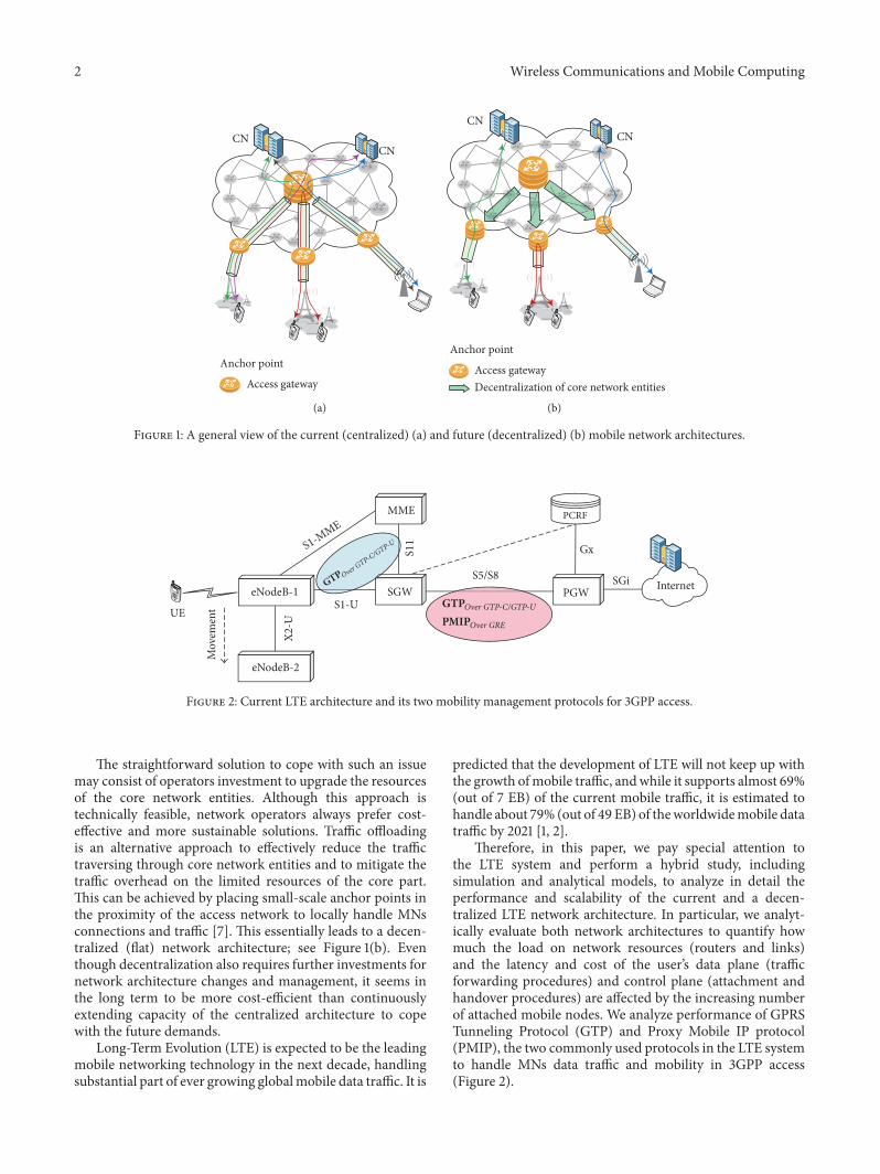
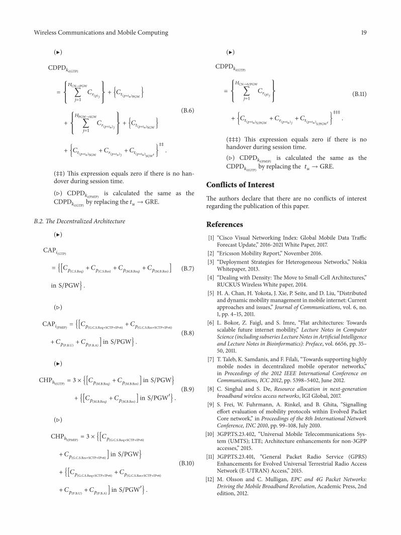