Embed Size (px)
Citation preview
1
Quantifying the energy of Terahertz fields using Electro-Optical Sampling
Tom George
LCLS, Science Undergraduate Laboratory Internship Program
San Jose State University
SLAC National Accelerator Laboratory
Menlo Park, CA
17 August 2012
Prepared in partial fulfillment of the requirement of the Office of Science, Department of Energy’s Science Undergraduate Laboratory Internship under the direction of Alan Fry in the LCLS at SLAC National Accelerator Laboratory.
Participant: __________________________________
Signature
Research Advisor: __________________________________
Signature
2
Table of Contents
Abstract……………………………………………………………………………3
Introduction………………………………………………………………………..4-5
Materials and Methods…………………………………………………………….6-7
Results and Discussion…………………………………………………………….7-8
Conclusion…………………………………………………………………………8
Acknowledgements………………………………………………………………...8-9
References…………………………………………………………………………10-11
3
Abstract
Quantifying Terahertz fields using Electro-Optical sampling. TOM GEORGE ( San Jose State
University, San Jose, Ca 95112) ALAN FRY and MATTHIAS HOFFMANN(Linac Coherent
Light Source, SLAC, Menlo Park, Ca 94025)
The pump-probe technique is an easy and common way to look into the state of a
material after it has been hit with a Terahertz or any other pulse. An electro-optic sample is
“pumped” with a Terahertz pulse and soon afterwards is “probed” by another laser pulse. This
pumped induced probe goes through birefringence as it goes through the electro-optic sample.
Two photodiodes, which receive their sample clock from the laser, capture the energy of each
laser pulse and sends it to a data acquisition card for easy processing. This method allows for
detection of very small pump-probe signals with relatively the same accuracy as a lock-in
amplifier.
4
Introduction
Terahertz(THz) signals exist in an area called the THz gap which lies between the
infrared and microwaves on the electromagnetic spectrum. Discovered over 100 years ago [1]
research was relatively stagnant due to the unavailability of sources to produce powerful enough
THz signals. However with the advent of femtosecond lasers and sources such as the Free
Electron Laser (FEL), production of powerful THz signals has been possible. Research in
Terahertz time domain spectroscopy has revealed interesting phenomena in materials when used
in molecular to astronomic studies [1].
THz pulses have a wide variety of uses which range from medical, scientific, and even
security. What make Terahertz signals perfect for many applications is its non-ionizing
properties. It can pass through objects such as clothing, wood, paper, plastics, etc but cannot pass
through water or metal [5]. This could be an alternative to screeners with it’s ability to not only
detect illegal materials such as narcotics and explosives, such as C4, but to also provide sub x-
ray like images without the harmful radiation. Applications in the future can include detection of
explosives and medical imaging. This is all possible with Terahertz spectroscopy since many
materials give off distinct spectra when hit with Terahertz signals [3].
Reliable Terahertz generating sources have just sprung up in the last few decades. One
way to generate Terahertz signals is to use ultra-short pulses using a Titanium-Sapphire laser,
producing pulse durations of 80fs, using a process called optical rectification [4]. In optical
rectification, an ultrashort laser pulse goes through a crystal, such as lithium niobate, which
5
produces terahertz pulses [4]. When the ultrashort laser pulse is sent through a specific crystal,
the quick change in polarization creates terahertz radiation [4].
To characterize the electric field of a THz pulse, after it goes through a certain sample,
electro-optic sampling is used. After the THz pulse has been generated it will go through an
electro-optic crystal which becomes birefringent while the THz pulse is present [4]. The
birefringence of the crystal causes a linearly polarized probe pulse that travels through the crystal
at the same speed of the THz pulse to become elliptically polarized [4]. The elliplicity can be
measured by splitting the two polarization components with a polarizer, and by sending them to
two photodiodes for processing. The known electro-optic coefficient of the detection crystal can
be used to determine the field strength of the THz signal from the difference in the detected
photo diode signals.
The photodiodes convert the polarization components of the probe femtosecond laser
pulse into an electrical signal, typically a voltage pulse of a few hundred mV with a duration of
about 100ns. The amount of light incident on the photodiode is proportional to either the area
under voltage pulse curve or find its peak. Normally all of this is done using a lock-in amplifier
but because of how a lock-in amplifier manipulates its data, this can take an excessive amount of
time to receive an output. To get around this problem we have used a data acquisition card
(DAQ) which can easily measure the energy of every pulse and through simple arithmetic,
E = !!!!!!
, plot the data.
6
Materials and Methods
Using a DAQ systems provides advantages in terms of quantification speed and
versatility. The laser used is a 1kHz Ti: Sapphire with a wavelength of 800nm, a pulse energy of
3.5mj and a pulse duration of 80fs [2]. This laser is split by a beam splitter into a “probe” pulse
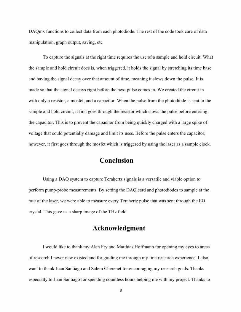
and another beam that goes into a THz signal generator. The pulse that was sent to the THz
signal generator, passes through an optical modulator that runs at 500Hz which blocks every
other pulse. The pulses that did make it through went through a lithium niobate crystal which
produced the Terahertz signals as shown in Figure 1. This signal is then sent to an electro-optic
detection crystal which becomes birefringent while the THz pulse is present. The “probe” pulse
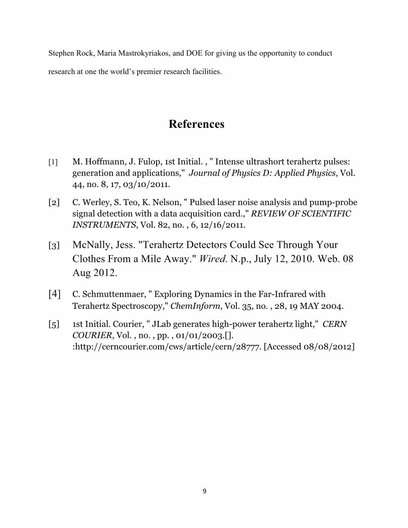
on the other hand is sent to a delay stage which delays the pulse by moving the stage back and
forth, depending on the desired time delay, before it goes through an electro-optic(EO) crystal
that has been excited by a THz pulse. The delay stage, as shown in Figure 2, is used to probe the
EO sample over time by moving it backwards or forwards, depending on the case, after every
sample.
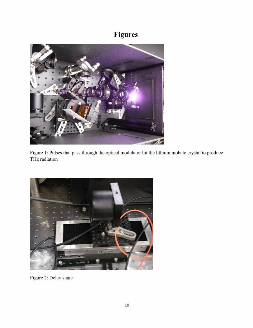
To capture the energy of the Terahertz through the EO crystal we use two photodiodes.
Two THORLABS DET100A photodiodes, shown in Figure 3, are used to capture the probe
pulse polarization components after interacting with the THz inside the EO crystal. The sample
clock of the DAQ card was taken from the Ti: Sapphire laser, meaning every pulse from the laser
is measured. The voltage pulses from the two photodiodes have a pulse decay of 80ns which
decays before the next pulse arrives. From this point there are various ways to capture the data.
A few ways are to use a lock-in amplifier, a current preamplifier with a box-car integrator, or use
7
a sample and hold circuit/integrator circuit. Since we were trying to find a better method than the
lock-in amplifier the best choice would have been to use a current preamplifier which would then
go into a boxcar integrator to give us the energy of each pulse. This would have been the easiest
method to implement but also carries along with it the highest cost at around $15, 000 for the
setup. A cheaper alternative is to use a sample and hold circuit which increases the time-base of
the signal, making if easier for the DAQ card to sample at its peak and capture the data. The
DAQ card we used was a National Instruments NI-6251, which has a maximum sampling rate of
1.25 ms/s at 16 bit resolution.
Results and Discussion
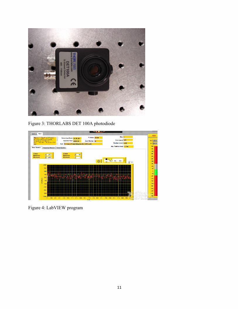
The data acquired from the photodiodes were processed in LabVIEW, shown in Figure 4.
LabVIEW allows you to create virtual instruments called VIs which can be used to control and
obtain data from various sources. Since we were using a DAQ card on a Windows machine we
were able to take advantage of the DAQmx function which makes data acquisition using an NI
DAQ extremely easy. The DAQmx function allows you to set where your signal is coming from,
triggering, and sampling all in one place. Two of these functions were used to capture the data
from the DAQ card for further use.
With my limited time and the features I still had to implement, I decided to try and
modify a VI that was currently being used to capture the energy of Terahertz signals but was
doing so using a lock-in amplifier. I was able to accomplish this by simply removing parts of the
code where information was being sent to the lock-in amplifier and initializing it. After doing
this I found where the data was being taken from the lock-in amplifier and replaced it with two
8
DAQmx functions to collect data from each photodiode. The rest of the code took care of data
manipulation, graph output, saving, etc
To capture the signals at the right time requires the use of a sample and hold circuit. What
the sample and hold circuit does is, when triggered, it holds the signal by stretching its time base
and having the signal decay over that amount of time, meaning it slows down the pulse. It is
made so that the signal decays right before the next pulse comes in. We created the circuit in
with only a resistor, a mosfet, and a capacitor. When the pulse from the photodiode is sent to the
sample and hold circuit, it first goes through the resistor which slows the pulse before entering
the capacitor. This is to prevent the capacitor from being quickly charged with a large spike of
voltage that could potentially damage and limit its uses. Before the pulse enters the capacitor,
however, it first goes through the mosfet which is triggered by using the laser as a sample clock.
Conclusion
Using a DAQ system to capture Terahertz signals is a versatile and viable option to
perform pump-probe measurements. By setting the DAQ card and photodiodes to sample at the
rate of the laser, we were able to measure every Terahertz pulse that was sent through the EO
crystal. This gave us a sharp image of the THz field.
Acknowledgment
I would like to thank my Alan Fry and Matthias Hoffmann for opening my eyes to areas
of research I never new existed and for guiding me through my first research experience. I also
want to thank Juan Santiago and Salem Cherenet for encouraging my research goals. Thanks
especially to Juan Santiago for spending countless hours helping me with my project. Thanks to
9
Stephen Rock, Maria Mastrokyriakos, and DOE for giving us the opportunity to conduct
research at one the world’s premier research facilities.
References
[1] M. Hoffmann, J. Fulop, 1st Initial. , " Intense ultrashort terahertz pulses: generation and applications," Journal of Physics D: Applied Physics, Vol. 44, no. 8, 17, 03/10/2011.
[2] C. Werley, S. Teo, K. Nelson, " Pulsed laser noise analysis and pump-probe signal detection with a data acquisition card.," REVIEW OF SCIENTIFIC INSTRUMENTS, Vol. 82, no. , 6, 12/16/2011.
[3] McNally, Jess. "Terahertz Detectors Could See Through Your Clothes From a Mile Away." Wired. N.p., July 12, 2010. Web. 08 Aug 2012.
[4] C. Schmuttenmaer, " Exploring Dynamics in the Far-Infrared with Terahertz Spectroscopy," ChemInform, Vol. 35, no. , 28, 19 MAY 2004.
[5] 1st Initial. Courier, " JLab generates high-power terahertz light," CERN COURIER, Vol. , no. , pp. , 01/01/2003.[]. :http://cerncourier.com/cws/article/cern/28777. [Accessed 08/08/2012]
10
Figures
Figure 1: Pulses that pass through the optical modulator hit the lithium niobate crystal to produce THz radiation
Figure 2: Delay stage
11
Figure 3: THORLABS DET 100A photodiode
Figure 4: LabVIEW program

![Highly Efficient Terahertz Radiation from Thin Foil ... · 3 THz time-domain spectroscopy (TDS) system with direct spatial encoding pump-probe electro-optical (EO) sampling [10] is](https://img.pdfslide.us/doc/110x75/5b02825f7f8b9a89598fb31a/highly-efficient-terahertz-radiation-from-thin-foil-thz-time-domain-spectroscopy.jpg)