Embed Size (px)
Citation preview
Synchronization inTimestamp-Based Cache Coherence Protocols
by
Quan Minh NguyenB.S., University of California, Berkeley (2014)
Submitted to the Department ofElectrical Engineering and Computer Science
in partial fulfillment of the requirements for the degree of
Master of Science in Electrical Engineering and Computer Science
at the
MASSACHUSETTS INSTITUTE OF TECHNOLOGY
June 2016
c� Massachusetts Institute of Technology 2016. All rights reserved.
Author . . . . . . . . . . . . . . . . . . . . . . . . . . . . . . . . . . . . . . . . . . . . . . . . . . . . . . . . . . . . . . . .Department of Electrical Engineering and Computer Science
May 20, 2016
Certified by. . . . . . . . . . . . . . . . . . . . . . . . . . . . . . . . . . . . . . . . . . . . . . . . . . . . . . . . . . . .Srinivas Devadas
Professor of Electrical Engineering and Computer ScienceThesis Supervisor
Accepted by . . . . . . . . . . . . . . . . . . . . . . . . . . . . . . . . . . . . . . . . . . . . . . . . . . . . . . . . . . .Professor Leslie A. Kolodziejski
Chair, Department Committee on Graduate Students

2
Synchronization in
Timestamp-Based Cache Coherence Protocols
by
Quan Minh Nguyen
Submitted to the Department of Electrical Engineering and Computer Scienceon May 20, 2016, in partial fulfillment of the
requirements for the degree ofMaster of Science in Electrical Engineering and Computer Science
AbstractSupporting computationally demanding workloads into the future requires that multi-processor systems support hundreds or thousands of cores. A cache coherence protocolmanages the memory cached by these many cores, but the storage overhead requiredby existing directory-based protocols to track coherence state scales poorly as thenumber of cores increases. The Tardis cache coherence protocol uses timestamps toavoid these scalability problems. We build a cycle-level multicore simulator that im-plements a version of the Tardis protocol that uses release consistency. Changingthe coherence protocol, which affects what memory values a processor can observe,changes inter-processor communication and synchronization, two processes crucial tothe operation of a multicore system. We construct Tardis versions of synchronizationprimitives and the atomic instructions they use, and compare them to their analogousimplementations on a directory-based cache coherent multicore system. Simulationson several benchmarks suggest that the Tardis system performs just as well as thebaseline system while preserving the ability to scale systems to hundreds or thousandsof cores.
Thesis Supervisor: Srinivas DevadasTitle: Professor of Electrical Engineering and Computer Science
3

4
Acknowledgments
Before I begin, I’d like to take this opportunity to thank the people who have made
this journey even remotely tractable. First, I would especially like to thank my
adviser, Srini, for providing key insights and guidance in this project and so warmly
welcoming me into the group two years ago. I am very grateful to Xiangyao, who
has never wavered from answering my unrelenting stream of questions about Tardis.
I aspire to emulate their contagious enthusiasm and wide-spanning knowledge. In
addition to my lab mates, my friends here have made my stay at the Institute at least
as much play as it is work; a heartfelt thank-you to Aaron, Fady, Lisa, Liz, Mehrdad,
Michael, and Wendy, who have been by my side the entire time. I am tremendously
grateful to Albert, Andrew, Krste, Stephen, and Yunsup of the ParLab and ASPIRE
Lab at Berkeley for intellectually launching me into the place where I am today. And,
finally, I want to thank my family: my mother, father, and sister (better known to
me as Má, Ba, and Uyên), for making it all possible. Just thinking of you and the
love you have shown me is always a source of inspiration and hope.
5

6
Contents
1 Introduction 13
2 Timestamp-Based Cache Coherence Protocols 17
2.1 The Tardis Cache Coherence Protocol . . . . . . . . . . . . . . . . . . 17
2.1.1 Timestamps . . . . . . . . . . . . . . . . . . . . . . . . . . . . 19
2.1.2 Reading Cache Blocks with Leases . . . . . . . . . . . . . . . 22
2.1.3 Writing Cache Blocks through Time Travel . . . . . . . . . . . 23
2.1.4 Renewals . . . . . . . . . . . . . . . . . . . . . . . . . . . . . 24
2.1.5 Per-Program Timestamps . . . . . . . . . . . . . . . . . . . . 25
2.1.6 Main Memory, Incoherent Memory, and I/O . . . . . . . . . . 27
2.2 Release Consistency and RISC-V . . . . . . . . . . . . . . . . . . . . 28
2.2.1 Fences . . . . . . . . . . . . . . . . . . . . . . . . . . . . . . . 29
2.2.2 Release and Acquire Instructions . . . . . . . . . . . . . . . . 31
2.3 Release Consistency Support for Tardis . . . . . . . . . . . . . . . . . 31
2.3.1 Compact Timestamp Configurations . . . . . . . . . . . . . . 32
2.3.2 Cache Transactions . . . . . . . . . . . . . . . . . . . . . . . . 34
2.3.3 Leases and Renewals in Tardis-RC . . . . . . . . . . . . . . . 37
2.4 Stale Reads . . . . . . . . . . . . . . . . . . . . . . . . . . . . . . . . 37
2.5 Techniques for Writing Tardis Programs . . . . . . . . . . . . . . . . 40
2.6 Previous Use of Timestamps for Coherence . . . . . . . . . . . . . . . 41
3 Atomic Instructions 43
3.1 Compare-and-Swap . . . . . . . . . . . . . . . . . . . . . . . . . . . . 43
7
3.2 Load-Reserved and Store-Conditional . . . . . . . . . . . . . . . . . . 45
3.3 Atomic Memory Operations . . . . . . . . . . . . . . . . . . . . . . . 48
4 Synchronization 51
4.1 Locks . . . . . . . . . . . . . . . . . . . . . . . . . . . . . . . . . . . . 51
4.1.1 The Mellor-Crummey-Scott Queue Lock . . . . . . . . . . . . 53
4.2 Barriers . . . . . . . . . . . . . . . . . . . . . . . . . . . . . . . . . . 54
5 Implementation 61
5.1 Guiding Principles . . . . . . . . . . . . . . . . . . . . . . . . . . . . 61
5.2 The RISC-V Rocket Microarchitecture . . . . . . . . . . . . . . . . . 62
5.2.1 Pipelining Timestamps . . . . . . . . . . . . . . . . . . . . . . 62
5.2.2 Extending the Memory Hierarchy . . . . . . . . . . . . . . . . 63
5.3 Network-on-Chip . . . . . . . . . . . . . . . . . . . . . . . . . . . . . 64
5.3.1 Manager/Client Abstraction . . . . . . . . . . . . . . . . . . . 64
5.3.2 Network Topology . . . . . . . . . . . . . . . . . . . . . . . . 65
6 Evaluation 67
6.1 Atomic Instructions . . . . . . . . . . . . . . . . . . . . . . . . . . . . 67
6.2 Synchronization Primitives . . . . . . . . . . . . . . . . . . . . . . . . 70
6.3 Application Performance . . . . . . . . . . . . . . . . . . . . . . . . . 72
7 Conclusion 81
7.1 Future Work . . . . . . . . . . . . . . . . . . . . . . . . . . . . . . . . 81
7.2 Concluding Remarks . . . . . . . . . . . . . . . . . . . . . . . . . . . 83
8
List of Figures
2-1 Simplified system diagram. . . . . . . . . . . . . . . . . . . . . . . . . 18
2-2 Last-level cache metadata layout. . . . . . . . . . . . . . . . . . . . . 18
2-3 Timeline diagram representing the validity of cache blocks within the
Tardis protocol. . . . . . . . . . . . . . . . . . . . . . . . . . . . . . . 21
2-4 Timeline diagram demonstrating a cache block read. . . . . . . . . . . 23
2-5 Timeline diagram demonstrating a cache block write. . . . . . . . . . 24
2-6 Timeline diagram demonstrating a cache block renewal. . . . . . . . . 25
2-7 Timeline diagram demonstrating interaction with main memory. . . . 27
2-8 Assembly code demonstrating a potential hit-under-miss situation a
cache. . . . . . . . . . . . . . . . . . . . . . . . . . . . . . . . . . . . 28
2-9 Timeline diagram demonstrating one of the limitations of Tardis with
sequential consistency. . . . . . . . . . . . . . . . . . . . . . . . . . . 29
2-10 Timeline diagram demonstrating a write-read fence in Tardis. . . . . 30
2-11 Timeline diagram demonstrating timestamps used in Tardis-RC. . . . 33
2-12 Example producer-consumer code. . . . . . . . . . . . . . . . . . . . . 38
2-13 Using synchronization to communicate updated data through an ex-
ternal cache block. . . . . . . . . . . . . . . . . . . . . . . . . . . . . 40
3-1 Hypothetical source code for a compare-and-swap instruction. . . . . 44
3-2 Timeline diagram demonstrating avoidance of the ABA problem. . . . 45
3-3 Load-reserved/store-conditional instruction sequence. . . . . . . . . . 45
3-4 Timeline diagram demonstrating livelock freedom on the LR/SC in-
struction pair. . . . . . . . . . . . . . . . . . . . . . . . . . . . . . . . 47
9
4-1 Source code for spin lock that uses compare-and-swap. . . . . . . . . 52
4-2 Diagram depicting linked-list nature of the MCS queue lock. . . . . . 54
4-3 Source code for an implementation of the Mellor-Crummey-Scott queue
lock. . . . . . . . . . . . . . . . . . . . . . . . . . . . . . . . . . . . . 55
4-4 Timeline diagram illustrating the effects of a barrier in physiological
time. . . . . . . . . . . . . . . . . . . . . . . . . . . . . . . . . . . . . 56
4-5 Source code for a sense-reversing barrier. . . . . . . . . . . . . . . . . 57
4-6 Barrier exploiting the exclusive ownership state to notify other cores. 58
6-1 Microbenchmark source code. . . . . . . . . . . . . . . . . . . . . . . 68
6-2 Performance of the MCS queue lock microbenchmark. . . . . . . . . . 71
6-3 Performance of a barrier microbenchmark. . . . . . . . . . . . . . . . 72
6-4 Performance of a vector-vector add benchmark exhibiting false sharing. 74
6-5 Performance of a vector-vector addition benchmark without false sharing. 75
6-6 Number of acquire messages sent on the TileLink networks. . . . . . . 76
6-7 Number of acquire messages sent on the TileLink networks. . . . . . . 77
6-8 Performance of a matrix-matrix multiplication. . . . . . . . . . . . . . 78
10
List of Tables
1-1 Size and latencies of a computer’s memory hierarchy. . . . . . . . . . 14
2-1 Timestamps for Tardis-SC, a sequentially consistent version of Tardis. 21
2-2 Timestamp update rules for the manager in the sequentially consistent
version of the Tardis cache coherence protocol. . . . . . . . . . . . . . 26
2-3 Timestamp update rules for the manager in the sequentially consistent
version of the Tardis cache coherence protocol. . . . . . . . . . . . . . 26
2-4 Message types used in Tardis. . . . . . . . . . . . . . . . . . . . . . . 26
2-5 Timestamp update rules needed to support relaxed consistency mem-
ory models. . . . . . . . . . . . . . . . . . . . . . . . . . . . . . . . . 32
2-6 Timestamps for Tardis-RC, a release-consistent version of Tardis, as
implemented in this thesis. . . . . . . . . . . . . . . . . . . . . . . . . 33
2-7 Actions performed by the client in the Tardis cache coherence protocol. 35
2-8 Actions performed by the manager in the Tardis cache coherence protocol. 36
2-9 Guidelines for timestamps to be sent along with messages to the last-
level cache during cache misses. . . . . . . . . . . . . . . . . . . . . . 37
5-1 Logical networks in the TileLink coherence protocol abstraction. . . . 64
5-2 Timestamps required in network messages for coherence in the Tardis
protocol. . . . . . . . . . . . . . . . . . . . . . . . . . . . . . . . . . . 65
5-3 Evaluation system configuration. . . . . . . . . . . . . . . . . . . . . 66
6-1 Performance of the load-reserved/store-conditional microbenchmark. . 68
6-2 Performance of the atomic memory operation microbenchmark. . . . 69
11

12
Chapter 1
Introduction
We must build multicore systems that scale well to hundreds or thousands of cores to
run applications increasingly necessary for progress and discovery in modern society.
These systems have become ubiquitous in everyday life, from mobile platforms to
datacenter computers. Even systems with one microprocessor may have multiple cores
running independently and in parallel. Computer architects have taken advantage of
the falling cost of transistors and evolving circuit fabrication techniques to increase
both the number of cores and the amount of memory or a single system.
Low-latency, high-throughput memory ensures that these applications run quickly.
On a shared-memory machine, all cores access the same main memory. However, these
cores rarely make changes directly to main memory – instead, they change the data
stored in a cache. A cache contains small sections of frequently used memory to exploit
spatial and temporal locality, and are essential in the design of high-performance com-
puters. Nowadays, the computer’s memory hierarchy separates a processor’s registers
from main memory with multiple levels of progressively larger caches. A processor’s
registers, at the top of the hierarchy, are fast, but small; main memory, at the bot-
tom of the hierarchy, is relatively slow, but large. By balancing the speed and size
trade-offs, the memory hierarchy grants the illusion of a vast, fast memory [1]. Yet,
programmers assume that any core may immediately observe the changes to memory
made by another core. The cache coherence system, which implements a specific
cache coherence protocol, communicates with the cores to keep cached data in a state
13
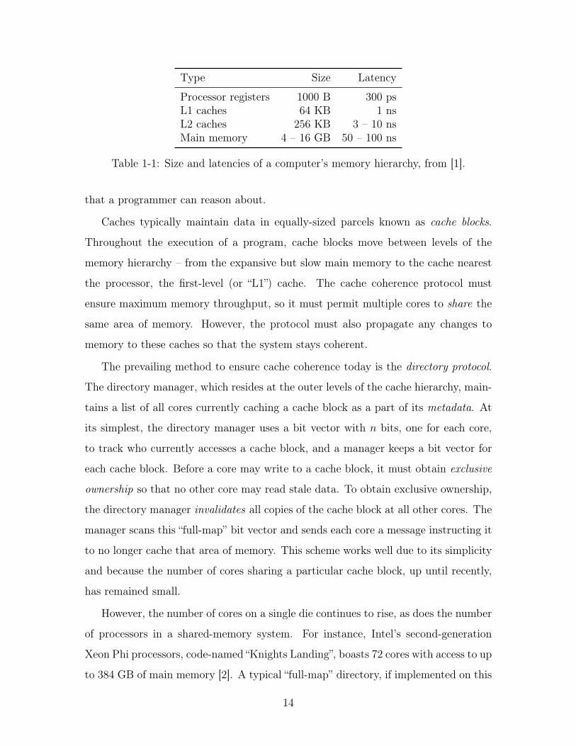
Type Size Latency
Processor registers 1000 B 300 psL1 caches 64 KB 1 nsL2 caches 256 KB 3 – 10 nsMain memory 4 – 16 GB 50 – 100 ns
Table 1-1: Size and latencies of a computer’s memory hierarchy, from [1].
that a programmer can reason about.
Caches typically maintain data in equally-sized parcels known as cache blocks.
Throughout the execution of a program, cache blocks move between levels of the
memory hierarchy – from the expansive but slow main memory to the cache nearest
the processor, the first-level (or “L1”) cache. The cache coherence protocol must
ensure maximum memory throughput, so it must permit multiple cores to share the
same area of memory. However, the protocol must also propagate any changes to
memory to these caches so that the system stays coherent.
The prevailing method to ensure cache coherence today is the directory protocol.
The directory manager, which resides at the outer levels of the cache hierarchy, main-
tains a list of all cores currently caching a cache block as a part of its metadata. At
its simplest, the directory manager uses a bit vector with n bits, one for each core,
to track who currently accesses a cache block, and a manager keeps a bit vector for
each cache block. Before a core may write to a cache block, it must obtain exclusive
ownership so that no other core may read stale data. To obtain exclusive ownership,
the directory manager invalidates all copies of the cache block at all other cores. The
manager scans this “full-map” bit vector and sends each core a message instructing it
to no longer cache that area of memory. This scheme works well due to its simplicity
and because the number of cores sharing a particular cache block, up until recently,
has remained small.
However, the number of cores on a single die continues to rise, as does the number
of processors in a shared-memory system. For instance, Intel’s second-generation
Xeon Phi processors, code-named “Knights Landing”, boasts 72 cores with access to up
to 384 GB of main memory [2]. A typical “full-map” directory, if implemented on this
14
system, would require 72 bits per cache block to represent all possible combinations of
sharers. This amount of storage would represent more than 10% metadata overhead
for a 64-byte cache block, and will only grow as the number of cores increases. Several
techniques [3, 4, 5] reduce the cost of scaling the directory, but no technique suitably
solves the problem of effectively broadcasting invalidation messages to all sharers.
Tardis, a timestamp-based cache coherence protocol, reduces the per-cache block
metadata overhead from O(n) to O(log n) in the number of sharers [6]. Instead of
tracking all sharers of a cache block, the Tardis protocol only tracks its exclusive
owner. To maintain coherence, the Tardis protocol also assigns each cache block a
set of timestamps. Each core, which gains a timestamp counter in this protocol, may
only read a cache block if it satisfies conditions on its counter and the cache block’s
timestamps. The Tardis protocol, which provably preserves sequential consistency [7],
opens the door to dramatically scaling the number of cores in a system by dispensing
with excess metadata.
We wish to understand the effects of a system running Tardis to establish a case
for future implementation in real-world systems. The first efforts at modeling the per-
formance of the Tardis protocol were completed in Graphite, a functional simulator
that only performs lax synchronization. In this model, cores are only synchronized
when they interact on “true synchronization” events [8], making it possible for sim-
ulated events to occur out-of-order from when they would occur on a real system.
However, synchronization is a necessary component of a parallel program running on
a multicore machine. Furthermore, Graphite cannot faithfully model effects that arise
from inter-processor communication, such as message latency and network contention,
even while modeling the memory (“full” mode). These shortcomings prevent us from
fully measuring and understanding Tardis, so we opt to model it with cycle-level
simulation.
15
Organization and Contributions of this Thesis
In this thesis, we study synchronization on a machine implementing the Tardis proto-
col on a cycle-level simulator in the interest of building it on a real platform, whether
synthesized for a field-programmable gate array (FPGA) or for fabrication. We mod-
ify a version of Tardis that supports sequential consistency (“Tardis-SC”) to produce
“Tardis-RC”, a version of Tardis that supports the release consistency memory model
in Chapter 2. Using Tardis-RC, we define new semantics for atomic instructions and
observe their impacts on synchronization primitives in Chapters 3 and 4. We imple-
ment a prototype cycle-level simulator in Chapter 5, the first known implementation
of Tardis-RC with cycle-level detail. In Chapter 6, we demonstrate the performance
of Tardis implementations of atomic instructions and synchronization primitives and
their baseline counterparts on several benchmarks. We summarize our findings and
discuss possibilities for future work in Chapter 7.
16
Chapter 2
Timestamp-Based Cache Coherence
Protocols
In this chapter, we provide an overview of the Tardis cache coherence protocol. First,
we introduce the sequentially consistent version of Tardis, Tardis-SC, as described in
[6]. We specify Tardis-RC, a version of Tardis that supports release consistency, to
match the architecture used in our cycle-level simulator. We also extend Tardis to
memory-mapped devices and input/output (I/O).
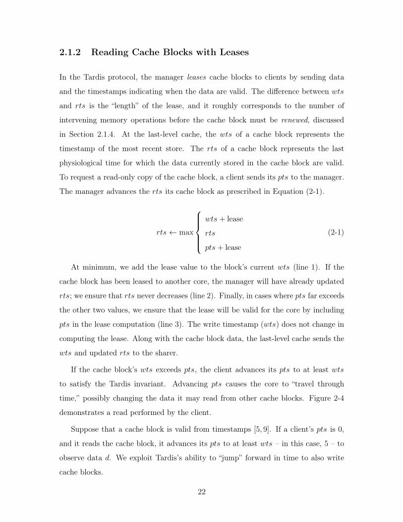
2.1 The Tardis Cache Coherence Protocol
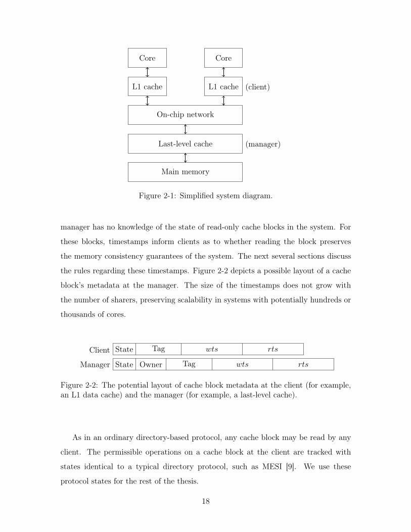
A system that implements the Tardis protocol has a number of cores and their caches
connected by an on-chip network that is eventually serviced by a shared last-level
cache, as typified in Figure 2-1. We refer to the system that maintains metadata
at the last-level cache as the manager. Clients, such as a core’s private data and
instruction caches, communicate with the manager to receive cache blocks. Clients
that may store modified blocks in a private cache are cached clients. Cached clients
require invalidations, while uncached clients (for instance, memory-mapped I/O) do
not. Tardis distinguishes itself from other cache coherence protocols because the
manager stores only the identity of the exclusive owner of the cache block, if it
exists, resulting in O(log n) metadata storage per cache block. Consequently, the
17
Core
L1 cache (client)
Core
L1 cache
On-chip network
Last-level cache (manager)
Main memory
Figure 2-1: Simplified system diagram.
manager has no knowledge of the state of read-only cache blocks in the system. For
these blocks, timestamps inform clients as to whether reading the block preserves
the memory consistency guarantees of the system. The next several sections discuss
the rules regarding these timestamps. Figure 2-2 depicts a possible layout of a cache
block’s metadata at the manager. The size of the timestamps does not grow with
the number of sharers, preserving scalability in systems with potentially hundreds or
thousands of cores.
Manager State Owner Tag wts rts
Client State Tag wts rts
Figure 2-2: The potential layout of cache block metadata at the client (for example,an L1 data cache) and the manager (for example, a last-level cache).
As in an ordinary directory-based protocol, any cache block may be read by any
client. The permissible operations on a cache block at the client are tracked with
states identical to a typical directory protocol, such as MESI [9]. We use these
protocol states for the rest of the thesis.
18
Time
The definition of “time” plays an important role in the Tardis protocol, so we take
care to define it here1. Physical time is the time observed in accordance with natural
phenomena; that is, wall-clock time. Logical time, perhaps most well-established as
Lamport clocks, numbers events based on a monotonically increasing counter without
regard to the passage of physical time [11]. Tardis combines both notions of time
to form physical-logical time, shortened to physiological time2, to establish a global
memory ordering between memory operations on cache blocks within a multiprocessor
system. Thus, something said to occur at the same physiological time may have
actually happened at two different physical times.
Memory models describe how the memory operations in a program (which defines
the program order) may be interleaved to form a global memory order. The sequential
consistency model stipulates that “the result of any execution is the same as if the
operations of all the processors were executed in some sequential order, and the
operations of each individual processor appear in this sequence in the order specified
by its program” [12]. The physiological time rule of Tardis-SC [6] establishes a global
memory order with timestamps assigned to memory operations:
Definition 1 (Physiological time rule). For an operation X to occur before Y in the
global memory order, X’s timestamp must be ordered before Y ’s timestamp, or if they
have the same timestamp, that X must be ordered before Y in the program.
2.1.1 Timestamps
The Tardis protocol assigns a write timestamp and a read timestamp to each cache
block, which we denote as wts and rts respectively. These timestamps do not cor-
respond to any actual operation, but instead specify which physiological times a
memory operation may occur. In Tardis-SC, the sequentially consistent version of
the Tardis protocol, each client keeps a timestamp counter to track its own sense of
1More precisely than “a big ball of wibbly wobbly timey wimey stuff.” [10]
2Physiological time has no relation to the biological notion of physiology.
19
physiological time, which we denote as pts.3 To satisfy the protocol’s requirement for
totally ordered timestamps, we represent physiological timestamps with integers. In
practice, 64-bit unsigned integers suffice and will never roll over in human-fathomable
timescales. A client can store pts in a register, while caches at the client and manager
can store wts and rts in a cache metadata array.
The write timestamp wts and the read timestamp rts denote the minimum and
maximum physiological times at which the cache block data assigned those time-
stamps are considered valid. To have valid cache block data, the read timestamp
must be no less than the write timestamp; that is, wts rts. In Section 2.1.2, we
will restrict reads to the cache block to clients that have a pts that fall within this
range. The validity of a cache block can then be expressed as an integer interval,
which we denote in this thesis as [wts, rts], emulating the notation for real-valued
intervals that contain both the start and end values. The Tardis protocol stipulates
a crucial invariant for these timestamps which we term the Tardis invariant :
Definition 2 (Tardis invariant). For a specific cache block, only one version of its
data may exist in a given timestamp interval [wts, rts].
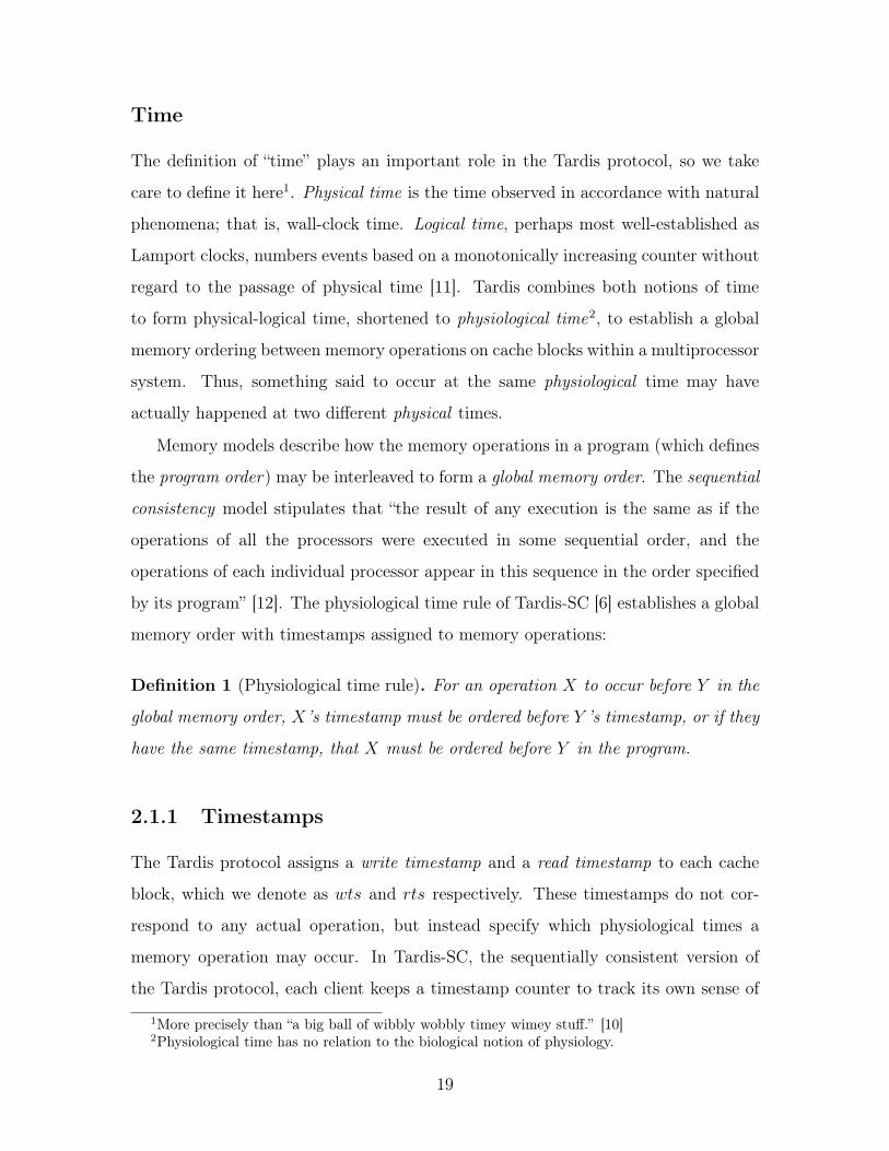
Figure 2-3 depicts the validity of a cache block on a timeline. In this figure,
physiological time increases to the right. The cache block’s data, d, are valid in the
interval [5, 9]. Reads to the cache block occurring at timestamps before 5 or after 9
may yield different data different from d.
An immediate consequence of this invariant is that changes to the data always
generate a new pair of timestamps with an interval disjoint from that of the old data.
A more subtle implication is that the value of rts may be increased as long as the
data in the cache block do not change. Increasing the rts of a cache block amounts to
“renewing“ a cache block. Renewals, covered in Section 2.1.4, allow clients to extend
the range of physiological times they may read the data. The Tardis invariant helps
programmers and computer architects reason about the function of the protocol. For
3The term processor timestamp gives rise to the abbreviation pts, but such a timestamp applies
to any caching client.
20

physiological time1 2 3 4 5 6 7 8 9 10
? ?d
wts rts
Figure 2-3: Timeline diagram representing the validity of a cache block. Physiologicaltime increases to the right, and all timestamps are integers. Rectangles on the samerow refer to the same cache block, and the text enclosed refers to the data. Thesmallest integer a rectangle overlaps represents that cache block’s wts; the largestinteger represents that cache block’s rts. We use a hatched pattern to emphasizethat the data outside wts and rts may not be known to the client.
instance, in Chapter 3 we demonstrate that the Tardis invariant can mitigate the
ABA problem for the compare-and-swap atomic instruction.
A client’s pts may only increase; however, pts only changes when the client in-
teracts with memory – pts does not increase with wall-clock time or the cycle count.
Reading memory may not alter a client’s pts at all. With a single timestamp, a
caching client can maintain sequential consistency; the next several sections review
Tardis-SC as specified in [6]. Physiological timestamps exist for uncached regions of
memory as well; they are discussed in Section 2.1.6. We summarize the timestamps
discussed so far, and their function, in Table 2-1.
Name Purpose
pts Tracks a client’s position in physiological time.
wts The physiological time for which the data assignedto this timestamp are valid.
rts At a client, the last physiological time for which thedata assigned are valid. At the manager, the lasttime for any client.
Table 2-1: Timestamps for Tardis-SC, a sequentially consistent version of Tardis.
21
2.1.2 Reading Cache Blocks with Leases
In the Tardis protocol, the manager leases cache blocks to clients by sending data
and the timestamps indicating when the data are valid. The difference between wts
and rts is the “length” of the lease, and it roughly corresponds to the number of
intervening memory operations before the cache block must be renewed, discussed
in Section 2.1.4. At the last-level cache, the wts of a cache block represents the
timestamp of the most recent store. The rts of a cache block represents the last
physiological time for which the data currently stored in the cache block are valid.
To request a read-only copy of the cache block, a client sends its pts to the manager.
The manager advances the rts its cache block as prescribed in Equation (2-1).
rts max
8>>><
>>>:
wts + lease
rts
pts + lease
(2-1)
At minimum, we add the lease value to the block’s current wts (line 1). If the
cache block has been leased to another core, the manager will have already updated
rts; we ensure that rts never decreases (line 2). Finally, in cases where pts far exceeds
the other two values, we ensure that the lease will be valid for the core by including
pts in the lease computation (line 3). The write timestamp (wts) does not change in
computing the lease. Along with the cache block data, the last-level cache sends the
wts and updated rts to the sharer.
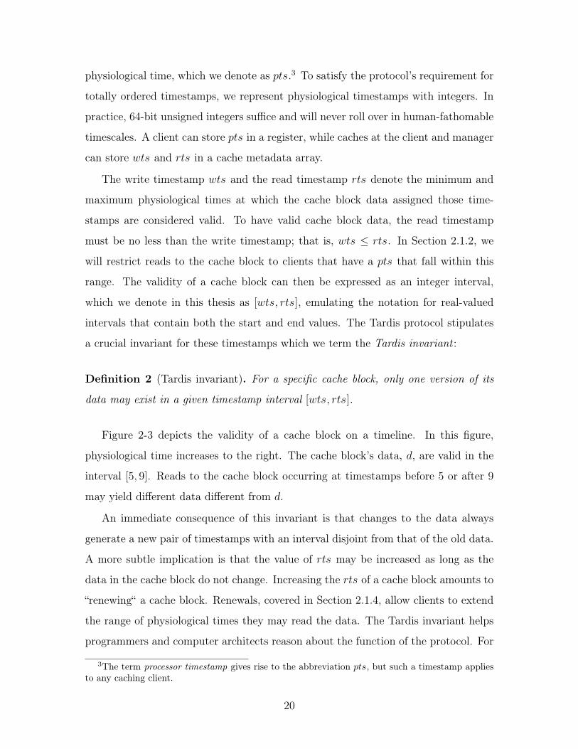
If the cache block’s wts exceeds pts, the client advances its pts to at least wts
to satisfy the Tardis invariant. Advancing pts causes the core to “travel through
time,” possibly changing the data it may read from other cache blocks. Figure 2-4
demonstrates a read performed by the client.
Suppose that a cache block is valid from timestamps [5, 9]. If a client’s pts is 0,
and it reads the cache block, it advances its pts to at least wts – in this case, 5 – to
observe data d. We exploit Tardis’s ability to “jump” forward in time to also write
cache blocks.
22
physiological time0 1 2 3 4 5 6 7 8 9 10
d
ptsold
ptsnew
read
Figure 2-4: Reading from a cache block. Because pts < wts, we advance pts to atleast wts to read the cache block’s data.
2.1.3 Writing Cache Blocks through Time Travel
Clients must request exclusive ownership of a cache block to modify its data. If
another client exclusively owns that cache block, the manager issues a writeback
request to that client before granting the original requester the exclusively-owned
cache block. In the directory protocol, the manager must also invalidate all read-only
copies of the cache block. In Tardis, invalidations of read-only copies of the cache
block are not necessary. To grant exclusive ownership of a cache block, the manager
sends its values of wts and rts for that cache block to the requester. Because rts
represents the last physiological time at which a client may read the current version
of that cache block, the earliest timestamp at which the data may change is rts + 1.
The client “jumps” to this physiological time to modify the data, thus lending the
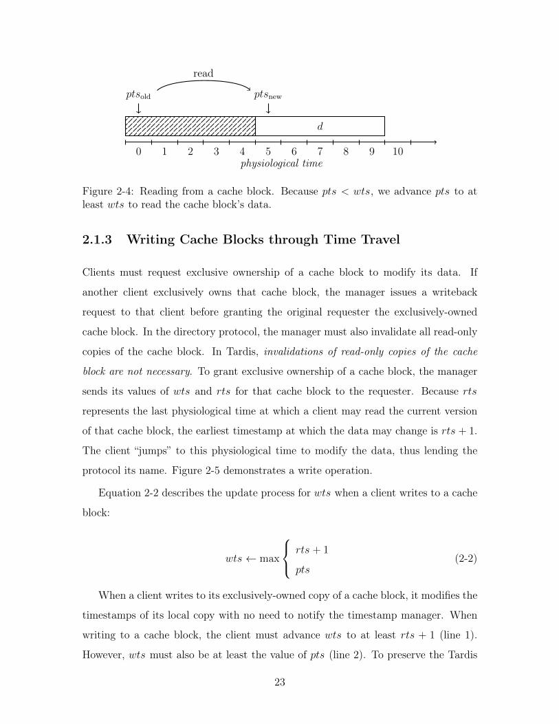
protocol its name. Figure 2-5 demonstrates a write operation.
Equation 2-2 describes the update process for wts when a client writes to a cache
block:
wts max
8<
:rts + 1
pts(2-2)
When a client writes to its exclusively-owned copy of a cache block, it modifies the
timestamps of its local copy with no need to notify the timestamp manager. When
writing to a cache block, the client must advance wts to at least rts + 1 (line 1).
However, wts must also be at least the value of pts (line 2). To preserve the Tardis
23
physiological time0 1 2 3 4 5 6 7 8 9 10
d d0
ptsold
ptsnew
write
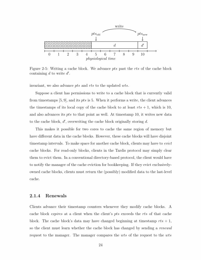
Figure 2-5: Writing a cache block. We advance pts past the rts of the cache blockcontaining d to write d0.
invariant, we also advance pts and rts to the updated wts.
Suppose a client has permissions to write to a cache block that is currently valid
from timestamps [5, 9], and its pts is 5. When it performs a write, the client advances
the timestamps of its local copy of the cache block to at least rts + 1, which is 10,
and also advances its pts to that point as well. At timestamp 10, it writes new data
to the cache block, d0, overwriting the cache block originally storing d.
This makes it possible for two cores to cache the same region of memory but
have different data in the cache blocks. However, these cache blocks will have disjoint
timestamp intervals. To make space for another cache block, clients may have to evict
cache blocks. For read-only blocks, clients in the Tardis protocol may simply clear
them to evict them. In a conventional directory-based protocol, the client would have
to notify the manager of the cache eviction for bookkeeping. If they evict exclusively-
owned cache blocks, clients must return the (possibly) modified data to the last-level
cache.
2.1.4 Renewals
Clients advance their timestamp counters whenever they modify cache blocks. A
cache block expires at a client when the client’s pts exceeds the rts of that cache
block. The cache block’s data may have changed beginning at timestamp rts + 1,
so the client must learn whether the cache block has changed by sending a renewal
request to the manager. The manager compares the wts of the request to the wts
24
of the cache block stored at the manager to discern whether the cache block has
changed. If they do not differ, the renewal succeeds, and the manager advances the
rts of the cache block at the manager to contain at least the client’s pts, also sent
with the renewal message. The manager completes the renewal process by informing
the client of the cache block’s rts, and no cache block data transfer is needed. If the
data have changed at the manager, the manager sends the client the modified data
alongside the updated timestamps as if it were an ordinary cache block read request.
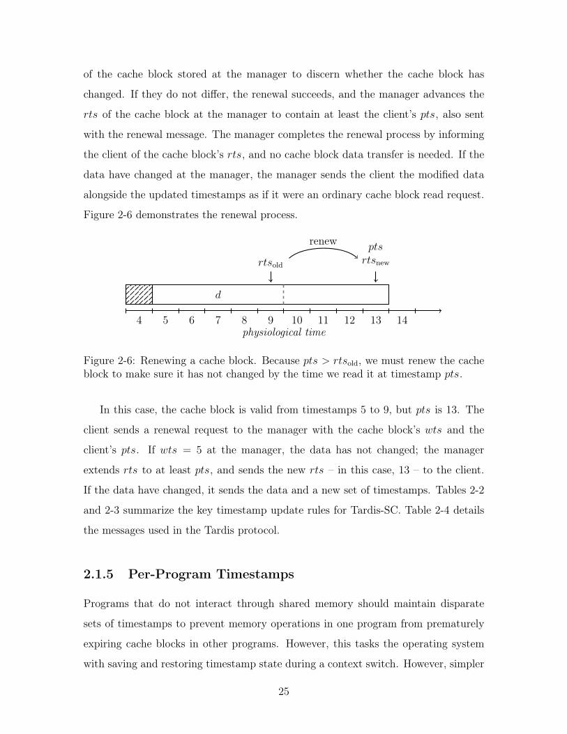
Figure 2-6 demonstrates the renewal process.
physiological time4 5 6 7 8 9 10 11 12 13 14
d
rtsold
ptsrts
new
renew
Figure 2-6: Renewing a cache block. Because pts > rtsold
, we must renew the cacheblock to make sure it has not changed by the time we read it at timestamp pts.
In this case, the cache block is valid from timestamps 5 to 9, but pts is 13. The
client sends a renewal request to the manager with the cache block’s wts and the
client’s pts. If wts = 5 at the manager, the data has not changed; the manager
extends rts to at least pts, and sends the new rts – in this case, 13 – to the client.
If the data have changed, it sends the data and a new set of timestamps. Tables 2-2
and 2-3 summarize the key timestamp update rules for Tardis-SC. Table 2-4 details
the messages used in the Tardis protocol.
2.1.5 Per-Program Timestamps
Programs that do not interact through shared memory should maintain disparate
sets of timestamps to prevent memory operations in one program from prematurely
expiring cache blocks in other programs. However, this tasks the operating system
with saving and restoring timestamp state during a context switch. However, simpler
25
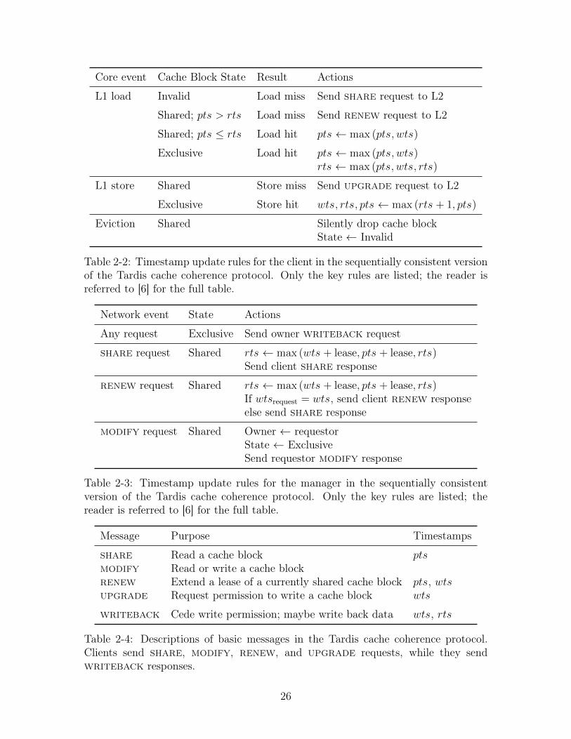
Core event Cache Block State Result Actions
L1 load Invalid Load miss Send share request to L2
Shared; pts > rts Load miss Send renew request to L2
Shared; pts rts Load hit pts max (pts, wts)
Exclusive Load hit pts max (pts, wts)rts max (pts, wts, rts)
L1 store Shared Store miss Send upgrade request to L2
Exclusive Store hit wts, rts, pts max (rts + 1, pts)
Eviction Shared Silently drop cache blockState Invalid
Table 2-2: Timestamp update rules for the client in the sequentially consistent versionof the Tardis cache coherence protocol. Only the key rules are listed; the reader isreferred to [6] for the full table.
Network event State Actions
Any request Exclusive Send owner writeback request
share request Shared rts max (wts + lease, pts + lease, rts)Send client share response
renew request Shared rts max (wts + lease, pts + lease, rts)If wts
request
= wts, send client renew responseelse send share response
modify request Shared Owner requestorState ExclusiveSend requestor modify response
Table 2-3: Timestamp update rules for the manager in the sequentially consistentversion of the Tardis cache coherence protocol. Only the key rules are listed; thereader is referred to [6] for the full table.
Message Purpose Timestamps
share Read a cache block ptsmodify Read or write a cache blockrenew Extend a lease of a currently shared cache block pts, wtsupgrade Request permission to write a cache block wts
writeback Cede write permission; maybe write back data wts, rts
Table 2-4: Descriptions of basic messages in the Tardis cache coherence protocol.Clients send share, modify, renew, and upgrade requests, while they sendwriteback responses.
26
systems running only a single program will not incur performance penalties, as there
is no context switching.
2.1.6 Main Memory, Incoherent Memory, and I/O
At system reset, no cache blocks are valid. Accesses to main memory bring cache
blocks to the last-level cache, but Tardis does not propagate timestamps to main
memory. In [6], the timestamp mts tracks accesses to main memory. For congruence
with our existing timestamps, we split mts into wtsmemory
and rtsmemory
, which re-
spectively represent the highest wts and rts of any cache block written back to main
memory. When a cache block is loaded from main memory, it assumes the time-
stamps wtsmemory
and rtsmemory
. Although it applies to all cache blocks brought in
from main memory, this conservative measure preserves coherence with a minimum
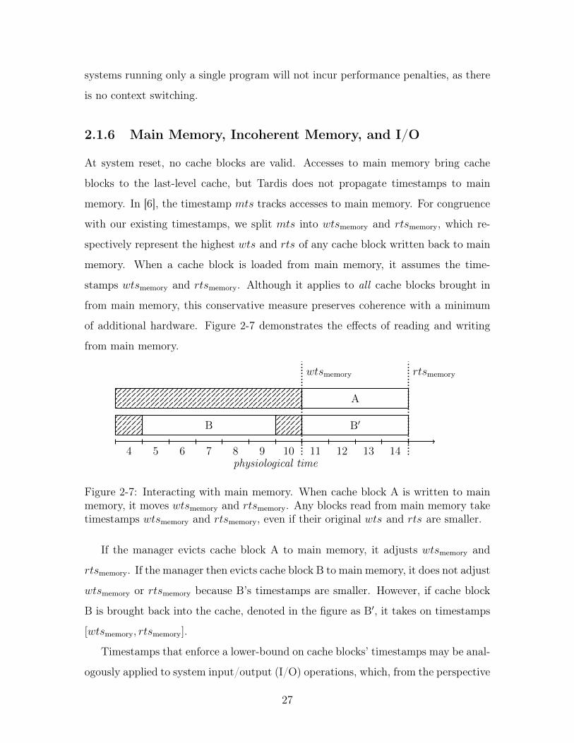
of additional hardware. Figure 2-7 demonstrates the effects of reading and writing
from main memory.
physiological time4 5 6 7 8 9 10 11 12 13 14
A
B B0
wtsmemory
rtsmemory
Figure 2-7: Interacting with main memory. When cache block A is written to mainmemory, it moves wts
memory
and rtsmemory
. Any blocks read from main memory taketimestamps wts
memory
and rtsmemory
, even if their original wts and rts are smaller.
If the manager evicts cache block A to main memory, it adjusts wtsmemory
and
rtsmemory
. If the manager then evicts cache block B to main memory, it does not adjust
wtsmemory
or rtsmemory
because B’s timestamps are smaller. However, if cache block
B is brought back into the cache, denoted in the figure as B0, it takes on timestamps
[wtsmemory
, rtsmemory
].
Timestamps that enforce a lower-bound on cache blocks’ timestamps may be anal-
ogously applied to system input/output (I/O) operations, which, from the perspective
27
of the last-level cache, behave like accesses to main memory. Timestamps may be
more generally applied to govern the interactions with data that comes from off-chip
(“incoherent” memory).
2.2 Release Consistency and RISC-V
Sequentially consistent systems impose major limitations on program optimizations
that reorder memory operations [13]. In fact, modern instruction set architectures
do not implement full sequential consistency [14]. However, Tardis-SC inherits the
limitations of sequentially-consistent computing. To demonstrate such a limitation,
consider a processor connected to a decoupled non-blocking L1 data cache executing
the instructions in Figure 2-8.
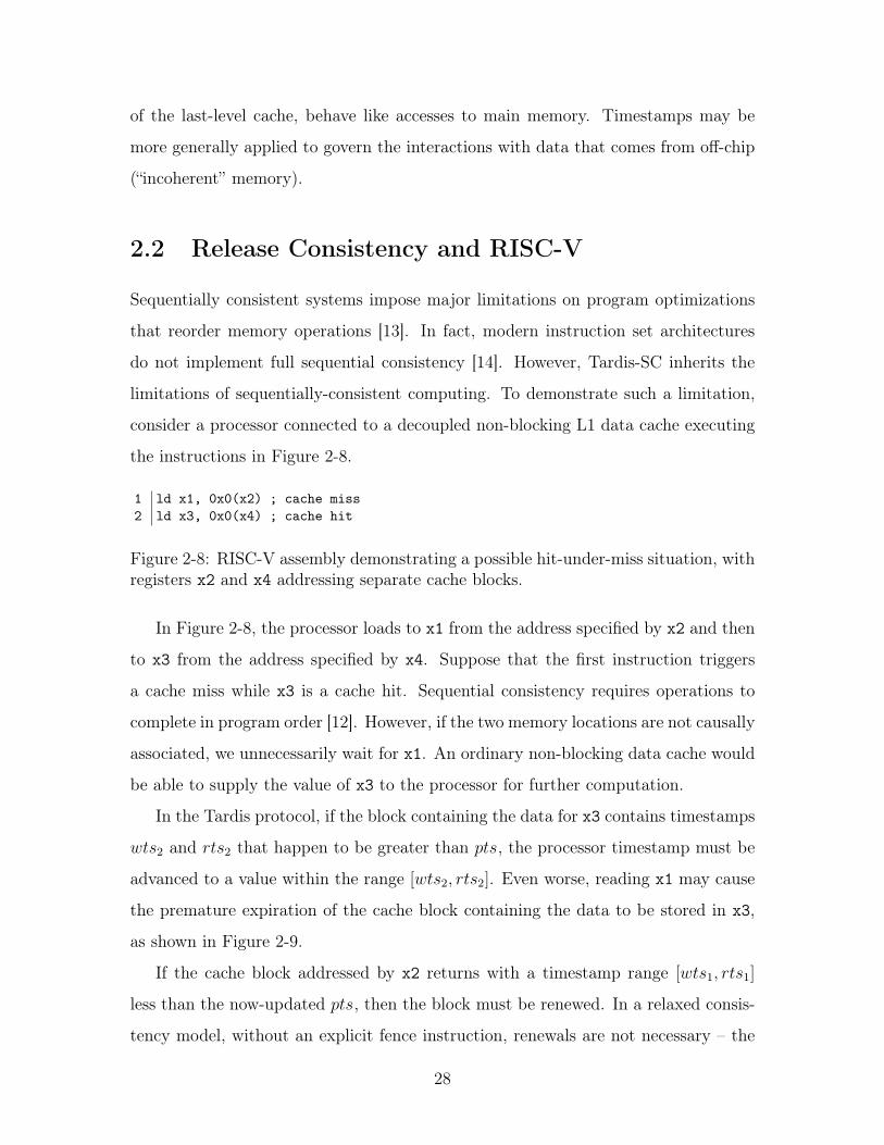
1 ld x1, 0x0(x2) ; cache miss2 ld x3, 0x0(x4) ; cache hit
Figure 2-8: RISC-V assembly demonstrating a possible hit-under-miss situation, withregisters x2 and x4 addressing separate cache blocks.
In Figure 2-8, the processor loads to x1 from the address specified by x2 and then
to x3 from the address specified by x4. Suppose that the first instruction triggers
a cache miss while x3 is a cache hit. Sequential consistency requires operations to
complete in program order [12]. However, if the two memory locations are not causally
associated, we unnecessarily wait for x1. An ordinary non-blocking data cache would
be able to supply the value of x3 to the processor for further computation.
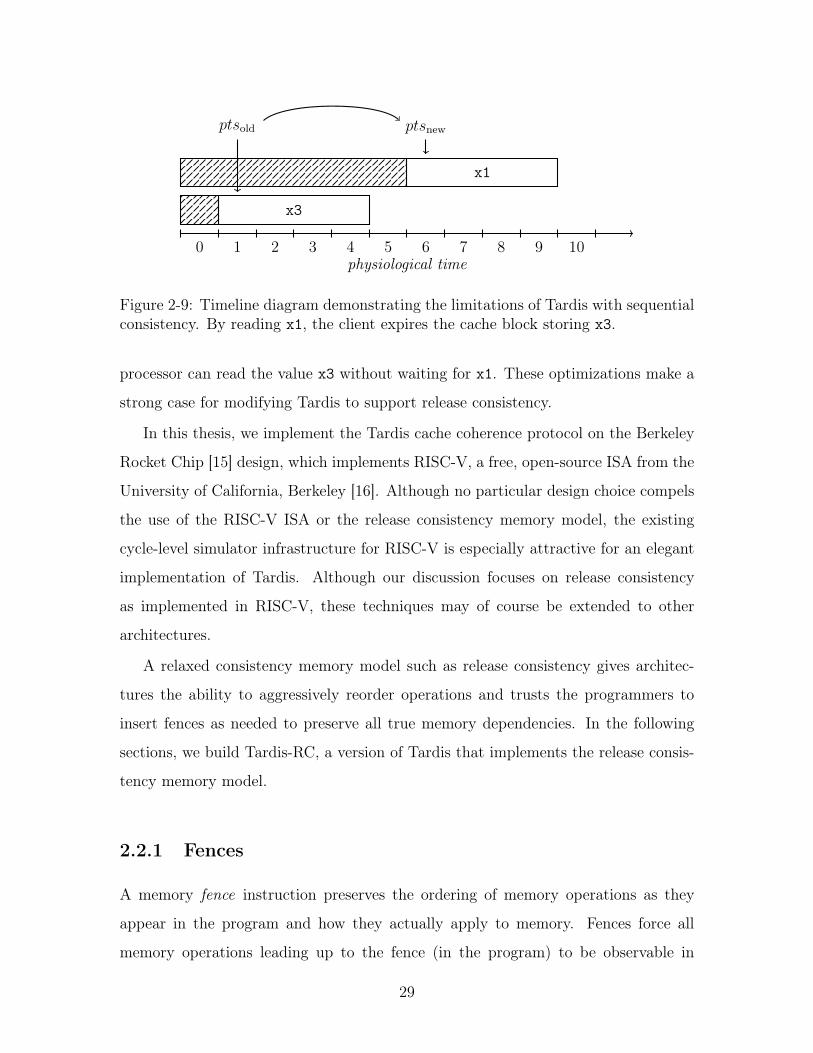
In the Tardis protocol, if the block containing the data for x3 contains timestamps
wts2
and rts2
that happen to be greater than pts, the processor timestamp must be
advanced to a value within the range [wts2
, rts2
]. Even worse, reading x1 may cause
the premature expiration of the cache block containing the data to be stored in x3,
as shown in Figure 2-9.
If the cache block addressed by x2 returns with a timestamp range [wts1
, rts1
]
less than the now-updated pts, then the block must be renewed. In a relaxed consis-
tency model, without an explicit fence instruction, renewals are not necessary – the
28
physiological time0 1 2 3 4 5 6 7 8 9 10
x3
x1
ptsold
ptsnew
Figure 2-9: Timeline diagram demonstrating the limitations of Tardis with sequentialconsistency. By reading x1, the client expires the cache block storing x3.
processor can read the value x3 without waiting for x1. These optimizations make a
strong case for modifying Tardis to support release consistency.
In this thesis, we implement the Tardis cache coherence protocol on the Berkeley
Rocket Chip [15] design, which implements RISC-V, a free, open-source ISA from the
University of California, Berkeley [16]. Although no particular design choice compels
the use of the RISC-V ISA or the release consistency memory model, the existing
cycle-level simulator infrastructure for RISC-V is especially attractive for an elegant
implementation of Tardis. Although our discussion focuses on release consistency
as implemented in RISC-V, these techniques may of course be extended to other
architectures.
A relaxed consistency memory model such as release consistency gives architec-
tures the ability to aggressively reorder operations and trusts the programmers to
insert fences as needed to preserve all true memory dependencies. In the following
sections, we build Tardis-RC, a version of Tardis that implements the release consis-
tency memory model.
2.2.1 Fences
A memory fence instruction preserves the ordering of memory operations as they
appear in the program and how they actually apply to memory. Fences force all
memory operations leading up to the fence (in the program) to be observable in
29
memory before proceeding to any memory operation in the program after the fence.
The RISC-V ISA provides a fine-grained fence instruction that specifies which
types of memory operations the fence affects. Any memory operation in the suc-
cessor set (in the program) may not be observed until all memory operations in the
predecessor set (in the program) have been observed. Bits in the instruction encoding
specify the members of the predecessor and successor sets, allowing arbitrary combi-
nations of memory fences between reads, writes, inputs, and outputs. For instance,
the fence instruction fence w,r prevents any read operation (r) from occurring until
all writes (w) before the fence have been observed.
Memory fences in Tardis also have an additional stipulation: that memory op-
erations occurring at physiological timestamps after the fence must occur after the
most recent (in physiological time) memory operation. We can derive the physiolog-
ical time requirements for the fence w,r instruction by examining the predecessor
and successor sets: if we must prevent reads from happening before writes, we must
require that read operations’ timestamps be lower-bounded by any previous write
operations’ timestamps.
physiological time4 5 6 7 8 9 10 11 12 13 14 15
d d0
wtsold
wtsnew
wtsmax
rtsmin
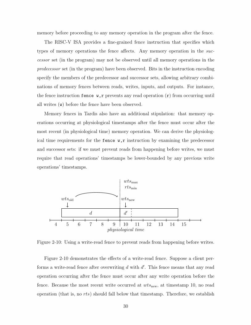
Figure 2-10: Using a write-read fence to prevent reads from happening before writes.
Figure 2-10 demonstrates the effects of a write-read fence. Suppose a client per-
forms a write-read fence after overwriting d with d0. This fence means that any read
operation occurring after the fence must occur after any write operation before the
fence. Because the most recent write occurred at wtsnew
, at timestamp 10, no read
operation (that is, no rts) should fall below that timestamp. Therefore, we establish
30
a minimum read timestamp rtsmin
that sets the lowest bound for a read at this client.
After performing the fence, a client may read d0, but only at timestamps greater than
10. In this thesis, we only consider read/write fences, although we can extend our
results to incorporate input/output memory fences.
2.2.2 Release and Acquire Instructions
Atomic instructions, described in greater detail in Chapter 3, modify memory with the
guarantee that no other core interposes on theses accesses – “indivisible” instructions.
To support release consistency, the RISC-V ISA allows atomic instructions to encode
that it represents an acquire or a release access. No memory operation after an acquire
operation (in program order) can occur before the acquire operation (in memory
order). Similarly, no memory operation before a release operation (in program order)
can occur after the release operation (in memory order).
2.3 Release Consistency Support for Tardis
To fully relax memory operation ordering while supporting memory fences, we in-
troduce additional timestamps. For arbitrary combinations of read/write memory
fences, we need four new timestamps, which express minimum and maximum val-
ues for rts and wts, which we will term wtsmin
, rtsmin
, wtsmax
, and rtsmax
. The
timestamps wtsmin
and rtsmin
express the earliest possible time at which memory
operations can occur with respect to previous fences or acquire/release operations.
The timestamps wtsmax
and rtsmax
express the earliest possible time at which the
client may complete all of its memory operations. Unlike the minimum timestamps,
the maximum timestamps do not enforce bounds; they merely track what values the
wtsmin
and rtsmin
should be set to upon the next fence instruction. It is important
to remark that the maximum timestamps required to observe all writes and reads are
not necessarily set by the wts and rts of a particular cache block. If the operation
may be observed at a timestamp less than wtsmax
or rtsmax
, then these timestamps
do not change.
31
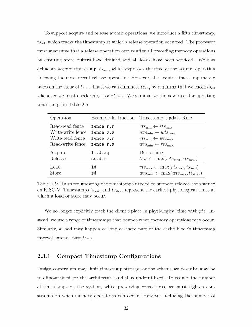
To support acquire and release atomic operations, we introduce a fifth timestamp,
tsrel
, which tracks the timestamp at which a release operation occurred. The processor
must guarantee that a release operation occurs after all preceding memory operations
by ensuring store buffers have drained and all loads have been serviced. We also
define an acquire timestamp, tsacq
, which expresses the time of the acquire operation
following the most recent release operation. However, the acquire timestamp merely
takes on the value of tsrel
. Thus, we can eliminate tsacq
by requiring that we check tsrel
whenever we must check wtsmin
or rtsmin
. We summarize the new rules for updating
timestamps in Table 2-5.
Operation Example Instruction Timestamp Update Rule
Read-read fence fence r,r rtsmin
rtsmax
Write-write fence fence w,w wtsmin
wtsmax
Write-read fence fence w,r rtsmin
wtsmax
Read-write fence fence r,w wtsmin
rtsmax
Acquire lr.d.aq Do nothingRelease sc.d.rl ts
rel
max(wtsmax
, rtsmax
)
Load ld rtsmax
max(rtsmax
, tsload
)
Store sd wtsmax
max(wtsmax
, tsstore
)
Table 2-5: Rules for updating the timestamps needed to support relaxed consistencyon RISC-V. Timestamps ts
load
and tsstore
represent the earliest physiological times atwhich a load or store may occur.
We no longer explicitly track the client’s place in physiological time with pts. In-
stead, we use a range of timestamps that bounds when memory operations may occur.
Similarly, a load may happen as long as some part of the cache block’s timestamp
interval extends past tsmin
.
2.3.1 Compact Timestamp Configurations
Design constraints may limit timestamp storage, or the scheme we describe may be
too fine-grained for the architecture and thus underutilized. To reduce the number
of timestamps on the system, while preserving correctness, we must tighten con-
straints on when memory operations can occur. However, reducing the number of
32
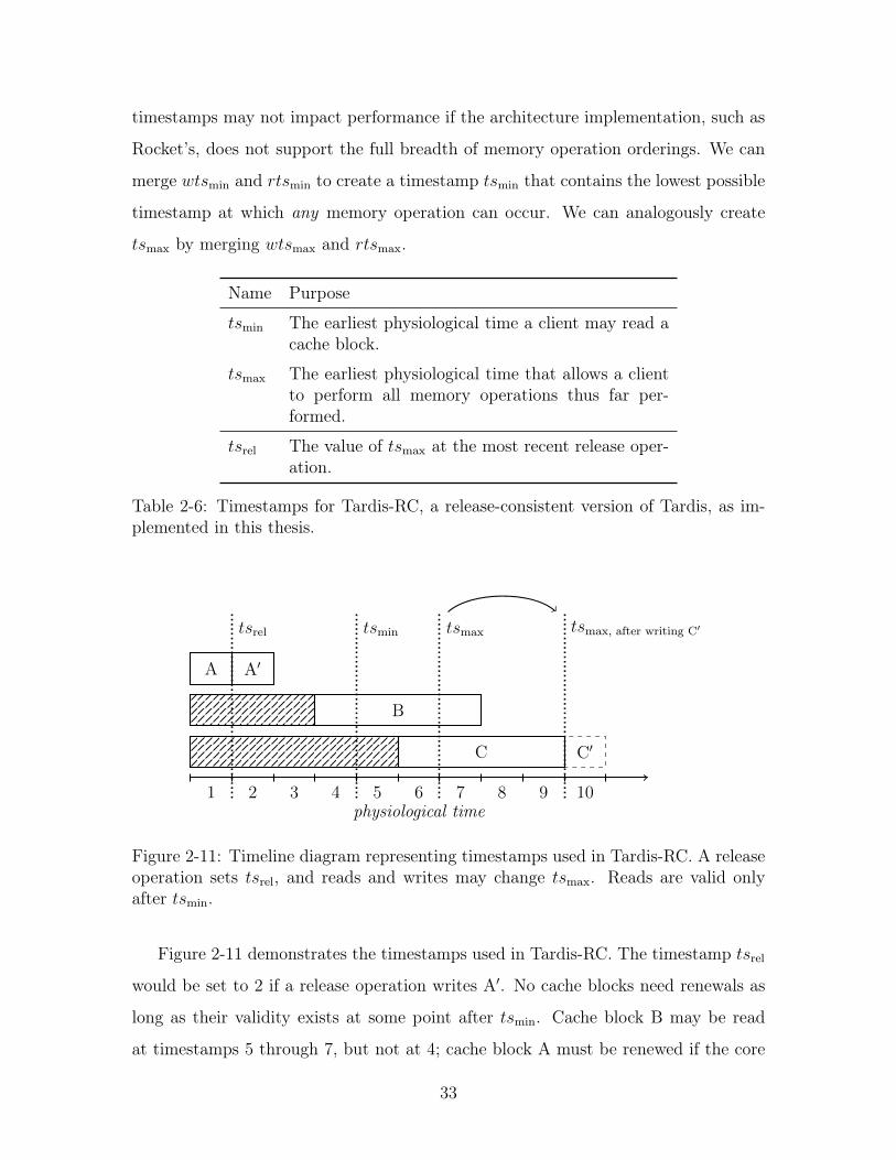
timestamps may not impact performance if the architecture implementation, such as
Rocket’s, does not support the full breadth of memory operation orderings. We can
merge wtsmin
and rtsmin
to create a timestamp tsmin
that contains the lowest possible
timestamp at which any memory operation can occur. We can analogously create
tsmax
by merging wtsmax
and rtsmax
.
Name Purpose
tsmin
The earliest physiological time a client may read acache block.
tsmax
The earliest physiological time that allows a clientto perform all memory operations thus far per-formed.
tsrel
The value of tsmax
at the most recent release oper-ation.
Table 2-6: Timestamps for Tardis-RC, a release-consistent version of Tardis, as im-plemented in this thesis.
physiological time1 2 3 4 5 6 7 8 9 10
A A0
B
C C0
tsrel
tsmin
tsmax
tsmax, after writing C
0
Figure 2-11: Timeline diagram representing timestamps used in Tardis-RC. A releaseoperation sets ts
rel
, and reads and writes may change tsmax
. Reads are valid onlyafter ts
min
.
Figure 2-11 demonstrates the timestamps used in Tardis-RC. The timestamp tsrel
would be set to 2 if a release operation writes A0. No cache blocks need renewals as
long as their validity exists at some point after tsmin
. Cache block B may be read
at timestamps 5 through 7, but not at 4; cache block A must be renewed if the core
33
loses exclusive ownership after writing A0. The timestamp tsmin
may only be moved
by a fence instruction – in the absence of fence instructions, clients may read cache
blocks B and C in any order. If a client writes to cache block C, it would be written
at timestamp 10; tsmax
would be set to 10 to express the highest timestamp of any
operation performed by the client.
To conserve even more space, we can combine tsmin
and tsrel
into just one time-
stamp, tsmin/rel
. Such a timestamp would be adjusted on every release operation and
fence.
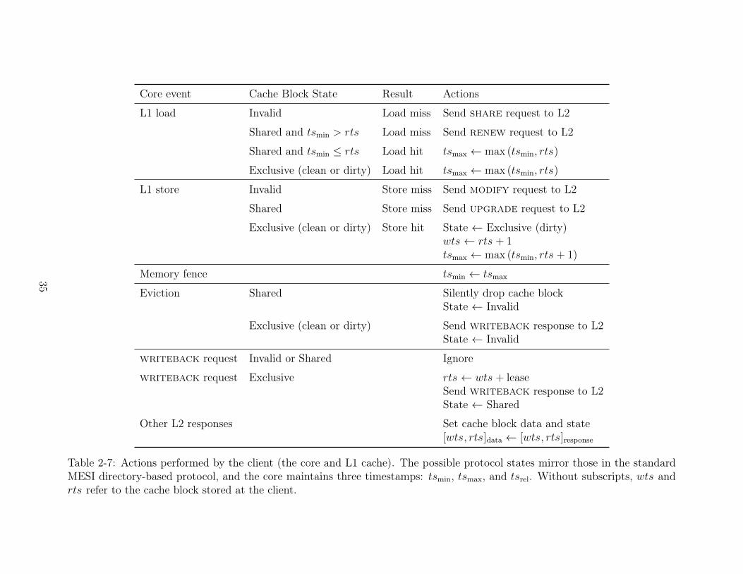
2.3.2 Cache Transactions
Tables 2-7 and 2-8 specify the timestamp update rules for the relaxed consistency
version of Tardis for the client and manager, respectively.
34
Core event Cache Block State Result Actions
L1 load Invalid Load miss Send share request to L2
Shared and tsmin
> rts Load miss Send renew request to L2
Shared and tsmin
rts Load hit tsmax
max (tsmin
, rts)
Exclusive (clean or dirty) Load hit tsmax
max (tsmin
, rts)
L1 store Invalid Store miss Send modify request to L2
Shared Store miss Send upgrade request to L2
Exclusive (clean or dirty) Store hit State Exclusive (dirty)wts rts + 1
tsmax
max (tsmin
, rts + 1)
Memory fence tsmin
tsmax
Eviction Shared Silently drop cache blockState Invalid
Exclusive (clean or dirty) Send writeback response to L2State Invalid
writeback request Invalid or Shared Ignore
writeback request Exclusive rts wts + leaseSend writeback response to L2State Shared
Other L2 responses Set cache block data and state[wts, rts]
data
[wts, rts]response
Table 2-7: Actions performed by the client (the core and L1 cache). The possible protocol states mirror those in the standardMESI directory-based protocol, and the core maintains three timestamps: ts
min
, tsmax
, and tsrel
. Without subscripts, wts andrts refer to the cache block stored at the client.
35
Network event Cache Block State Actions
Any request Invalid Load from main memorywts wts
mem
rts max (wts + lease, tsrequest
+ lease, rtsmem
)
Exclusive Send owner writeback request
share request Shared State Sharedrts max (wts + lease, ts
request
+ lease, rts)Send client share response
renew request Shared rts max (wts + lease, tsrequest
+ lease, rts)If wts
request
= wts, send core renew responseelse send share response
modify request Shared Owner requestorState ExclusiveSend requestor modify response
writeback response Write back data[wts, rts]
data
[wts, rts]response
Eviction Shared wtsmem
max (wtsmem
, wts)rts
mem
max (rtsmem
, rts)Store to main memory
Table 2-8: Actions performed by the manager (the last-level cache) in the Tardis cache coherence protocol, in response to actionsperformed by the core in Table 2-7. The last-level cache manages timestamps wts
mem
and rtsmem
, which are external to anycache block. Without subscripts, wts and rts refer to the cache block stored at the manager. Unlike the client, the managerhas three cache block states: Invalid, Shared, and Exclusive.
36
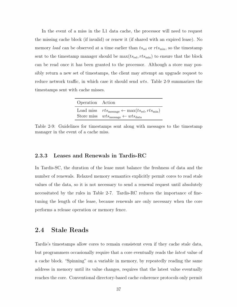
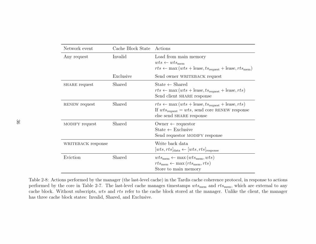
In the event of a miss in the L1 data cache, the processor will need to request
the missing cache block (if invalid) or renew it (if shared with an expired lease). No
memory load can be observed at a time earlier than tsrel
or rtsmin
, so the timestamp
sent to the timestamp manager should be max(tsrel
, rtsmin
) to ensure that the block
can be read once it has been granted to the processor. Although a store may pos-
sibly return a new set of timestamps, the client may attempt an upgrade request to
reduce network traffic, in which case it should send wts. Table 2-9 summarizes the
timestamps sent with cache misses.
Operation Action
Load miss rtsmessage
max(tsrel
, rtsmin
)
Store miss wtsmessage
wtsdata
Table 2-9: Guidelines for timestamps sent along with messages to the timestampmanager in the event of a cache miss.
2.3.3 Leases and Renewals in Tardis-RC
In Tardis-SC, the duration of the lease must balance the freshness of data and the
number of renewals. Relaxed memory semantics explicitly permit cores to read stale
values of the data, so it is not necessary to send a renewal request until absolutely
necessitated by the rules in Table 2-7. Tardis-RC reduces the importance of fine-
tuning the length of the lease, because renewals are only necessary when the core
performs a release operation or memory fence.
2.4 Stale Reads
Tardis’s timestamps allow cores to remain consistent even if they cache stale data,
but programmers occasionally require that a core eventually reads the latest value of
a cache block. “Spinning” on a variable in memory, by repeatedly reading the same
address in memory until its value changes, requires that the latest value eventually
reaches the core. Conventional directory-based cache coherence protocols only permit
37
1 static int x;23 void produce(int y)4 {5 x = y;6 }78 int consume()9 {
10 return x;11 }
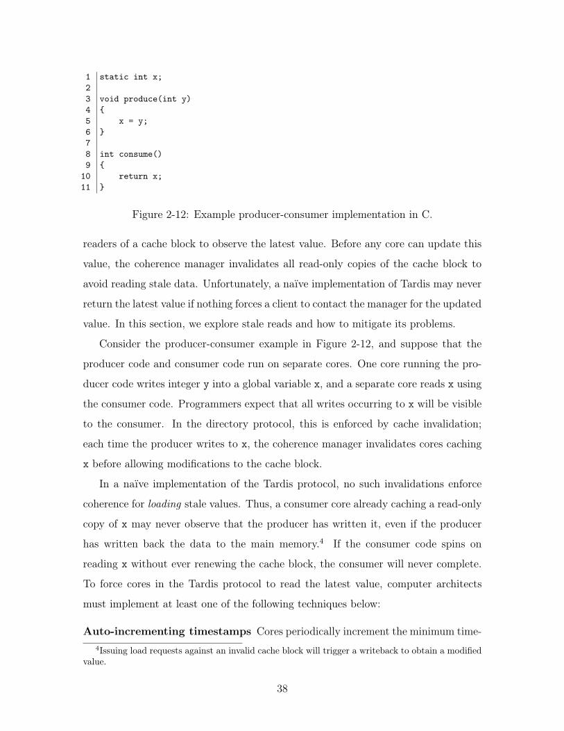
Figure 2-12: Example producer-consumer implementation in C.
readers of a cache block to observe the latest value. Before any core can update this
value, the coherence manager invalidates all read-only copies of the cache block to
avoid reading stale data. Unfortunately, a naïve implementation of Tardis may never
return the latest value if nothing forces a client to contact the manager for the updated
value. In this section, we explore stale reads and how to mitigate its problems.
Consider the producer-consumer example in Figure 2-12, and suppose that the
producer code and consumer code run on separate cores. One core running the pro-
ducer code writes integer y into a global variable x, and a separate core reads x using
the consumer code. Programmers expect that all writes occurring to x will be visible
to the consumer. In the directory protocol, this is enforced by cache invalidation;
each time the producer writes to x, the coherence manager invalidates cores caching
x before allowing modifications to the cache block.
In a naïve implementation of the Tardis protocol, no such invalidations enforce
coherence for loading stale values. Thus, a consumer core already caching a read-only
copy of x may never observe that the producer has written it, even if the producer
has written back the data to the main memory.4 If the consumer code spins on
reading x without ever renewing the cache block, the consumer will never complete.
To force cores in the Tardis protocol to read the latest value, computer architects
must implement at least one of the following techniques below:
Auto-incrementing timestamps Cores periodically increment the minimum time-4Issuing load requests against an invalid cache block will trigger a writeback to obtain a modified
value.
38
stamp at which a core may observe data, tsmin
. Eventually, tsmin
exceeds the
rts of the block and forces a renewal which produces the latest value. This is
the method presented in [6].
New instructions A new instruction to force the processor to load the latest value,
issuing a writeback to a core exclusively caching the cache block if necessary.
Take exclusive ownership A core obtaining the cache block in the exclusive state
will always read the latest data.
Synchronization Using the above methods, a core can signal through a separate
cache block that that the data has changed. Using a memory fence, the core
can observe the updated data.
Of the aforementioned techniques, automatically incrementing timestamps is one
of the simplest backwards-compatible solutions. This technique does not require
adding instructions to the ISA or program binary modifications, and will be essential
for legacy code. The time between increments of tsmin
requires careful tuning. Too
frequent increments will prematurely expire cache blocks, but too infrequent incre-
ments will cause long delays for programs that spin. As a result, this technique is
particularly poorly suited for spin locks, which are normally regarded as the simplest
solution for extremely short locking periods. Aggressively optimized architectures
implementing Tardis may increment tsmin
when spinning on memory is detected.
It may be attractive to implement a new instruction that forces the processor
to observe the latest value of the cache block. Such an instruction, however, would
require the core to send a message to the last-level cache. Worse yet, a core spinning on
a cache block, waiting for another core to update it, could flood the on-chip network.
Furthermore, this requires modifications to the instruction set and the creation of
a new network message, adding complexity to the hardware-software interface. We
conclude that this is not an effective way to obtain the latest data in a cache block.
Finally, cores can obtain a fresh copy of the cache block by letting another core
signal to it that the cache block has changed; that is, through synchronization. The
39
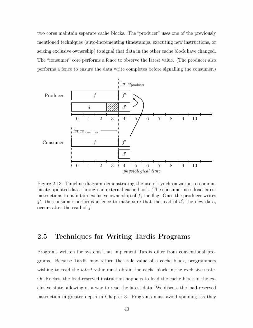
two cores maintain separate cache blocks. The “producer” uses one of the previously
mentioned techniques (auto-incrementing timestamps, executing new instructions, or
seizing exclusive ownership) to signal that data in the other cache block have changed.
The “consumer” core performs a fence to observe the latest value. (The producer also
performs a fence to ensure the data write completes before signalling the consumer.)
0 1 2 3 4 5 6 7 8 9 10
d d0
f f 0
fenceproducer
Producer
Consumer
physiological time0 1 2 3 4 5 6 7 8 9 10
f f 0
d0
fenceconsumer
Figure 2-13: Timeline diagram demonstrating the use of synchronization to commu-nicate updated data through an external cache block. The consumer uses load-latestinstructions to maintain exclusive ownership of f , the flag. Once the producer writesf 0, the consumer performs a fence to make sure that the read of d0, the new data,occurs after the read of f .
2.5 Techniques for Writing Tardis Programs
Programs written for systems that implement Tardis differ from conventional pro-
grams. Because Tardis may return the stale value of a cache block, programmers
wishing to read the latest value must obtain the cache block in the exclusive state.
On Rocket, the load-reserved instruction happens to load the cache block in the ex-
clusive state, allowing us a way to read the latest data. We discuss the load-reserved
instruction in greater depth in Chapter 3. Programs must avoid spinning, as they
40
may never make forward progress in the absence of auto-incrementing timestamps.
Leveraging the exclusive state to implement synchronization sidesteps the problem of
stale reads, as we will demonstrate in Chapter 4.
2.6 Previous Use of Timestamps for Coherence
Timestamps, including logical timestamps, are not new to coherent distributed shared
systems. Lamport discussed logical time in what are now called Lamport clocks [11].
Vector clocks track shared data by assigning timestamps to each processor. The
Ficus [17] and Bayou [18] systems tracked file version history with vector clocks and
permitted disconnected operation. Treadmarks [19] also uses vector timestamps to
manage distributed shared memory at the page level with a relaxed consistency model.
However, each vector timestamp contains as many timestamps as there are processors
in the system, so these schemes scale poorly to hundreds or thousands of cores.
Google’s Spanner system [20] distributes data across its datacenters using globally
synchronized timestamps. Tardis does not require globally synchronized timestamps,
and Spanner’s methods for ensuring consistency, including the use of atomic clocks,
are excessive for the scale at which Tardis operates.
Summary
In this chapter, we introduced the notion of physiological time and a sequentially
consistent version of Tardis. With additional timestamps, we augmented Tardis to
support a release consistency memory model as used in RISC-V, the ISA used by our
simulator infrastructure. We discussed techniques to obtain the latest data in a cache
block and how to write effective programs for Tardis. In the next chapter, we extend
physiological time to atomic instructions.
41

42
Chapter 3
Atomic Instructions
Atomic instructions allow processor to modify memory without any other processor
modifying the same part of memory. The name for these instructions arises from the
notion that no other operation may “divide” these instructions. They are necessary in
multiprocessor systems because ordinary loads and stores are not sufficient to perform
synchronization [21].
Many types of atomic instructions exist, but some of the most well-known today
include compare-and-swap (CAS), atomic memory operations (AMOs), and the load-
reserved/store-conditional (LR/SC) pair. These instructions have usability trade-offs
that make them suitable for some situations but not others. In this chapter, we take
advantage of the Tardis invariant to implement new forms of commonly-used atomic
instructions that eliminate some of the drawbacks affecting these instructions.
3.1 Compare-and-Swap
The compare-and-swap instruction has existed in the IBM System/370 [22] and in the
x86 architecture since the Intel 486 [23]. The compare-and-swap (CAS) instruction
compares a value in memory to one of the instruction’s operands; if so, the core
switches the value in memory with another operand [22]. It returns the old value
to the core. Invocations of compare-and-swap that fail the comparison do not affect
memory.
43
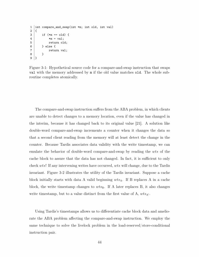
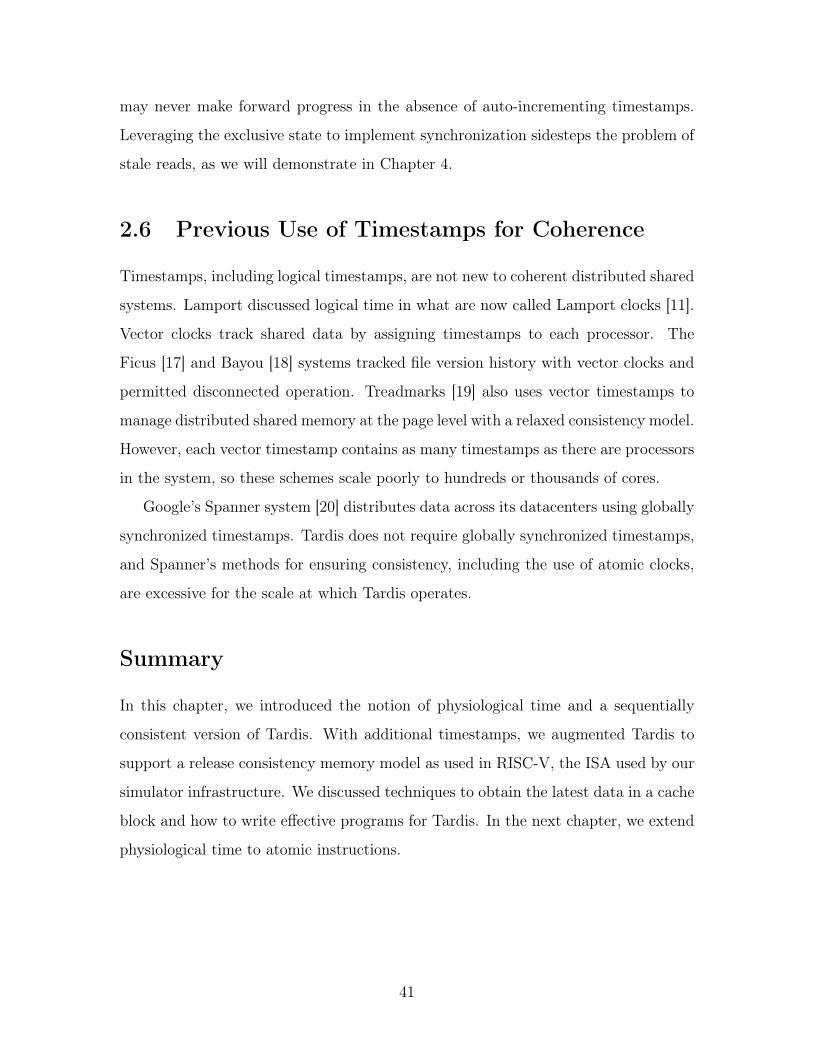
1 int compare_and_swap(int *m; int old, int val)2 {3 if (*m == old) {4 *m = val;5 return old;6 } else {7 return val;8 }9 }
Figure 3-1: Hypothetical source code for a compare-and-swap instruction that swapsval with the memory addressed by m if the old value matches old. The whole sub-routine completes atomically.
The compare-and-swap instruction suffers from the ABA problem, in which clients
are unable to detect changes to a memory location, even if the value has changed in
the interim, because it has changed back to its original value [21]. A solution like
double-word compare-and-swap increments a counter when it changes the data so
that a second client reading from the memory will at least detect the change in the
counter. Because Tardis associates data validity with the write timestamp, we can
emulate the behavior of double-word compare-and-swap by reading the wts of the
cache block to assure that the data has not changed. In fact, it is sufficient to only
check wts! If any intervening writes have occurred, wts will change, due to the Tardis
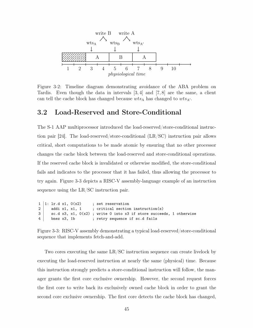
invariant. Figure 3-2 illustrates the utility of the Tardis invariant. Suppose a cache
block initially starts with data A valid beginning wtsA
. If B replaces A in a cache
block, the write timestamp changes to wtsB
. If A later replaces B, it also changes
write timestamp, but to a value distinct from the first value of A, wtsA
0 .
Using Tardis’s timestamps allows us to differentiate cache block data and amelio-
rate the ABA problem affecting the compare-and-swap instruction. We employ the
same technique to solve the livelock problem in the load-reserved/store-conditional
instruction pair.
44
physiological time1 2 3 4 5 6 7 8 9 10
A B A
wtsA
write B
wtsB
write A
wtsA
0
Figure 3-2: Timeline diagram demonstrating avoidance of the ABA problem onTardis. Even though the data in intervals [3, 4] and [7, 8] are the same, a clientcan tell the cache block has changed because wts
A
has changed to wtsA
0 .
3.2 Load-Reserved and Store-Conditional
The S-1 AAP multiprocessor introduced the load-reserved/store-conditional instruc-
tion pair [24]. The load-reserved/store-conditional (LR/SC) instruction pair allows
critical, short computations to be made atomic by ensuring that no other processor
changes the cache block between the load-reserved and store-conditional operations.
If the reserved cache block is invalidated or otherwise modified, the store-conditional
fails and indicates to the processor that it has failed, thus allowing the processor to
try again. Figure 3-3 depicts a RISC-V assembly-language example of an instruction
sequence using the LR/SC instruction pair.
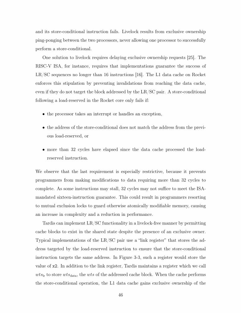
1 1: lr.d x1, 0(x2) ; set reservation2 addi x1, x1, 1 ; critical section instruction(s)3 sc.d x3, x1, 0(x2) ; write 0 into x3 if store succeeds, 1 otherwise4 bnez x3, 1b ; retry sequence if sc.d fails
Figure 3-3: RISC-V assembly demonstrating a typical load-reserved/store-conditionalsequence that implements fetch-and-add.
Two cores executing the same LR/SC instruction sequence can create livelock by
executing the load-reserved instruction at nearly the same (physical) time. Because
this instruction strongly predicts a store-conditional instruction will follow, the man-
ager grants the first core exclusive ownership. However, the second request forces
the first core to write back its exclusively owned cache block in order to grant the
second core exclusive ownership. The first core detects the cache block has changed,
45
and its store-conditional instruction fails. Livelock results from exclusive ownership
ping-ponging between the two processors, never allowing one processor to successfully
perform a store-conditional.
One solution to livelock requires delaying exclusive ownership requests [25]. The
RISC-V ISA, for instance, requires that implementations guarantee the success of
LR/SC sequences no longer than 16 instructions [16]. The L1 data cache on Rocket
enforces this stipulation by preventing invalidations from reaching the data cache,
even if they do not target the block addressed by the LR/SC pair. A store-conditional
following a load-reserved in the Rocket core only fails if:
• the processor takes an interrupt or handles an exception,
• the address of the store-conditional does not match the address from the previ-
ous load-reserved, or
• more than 32 cycles have elapsed since the data cache processed the load-
reserved instruction.
We observe that the last requirement is especially restrictive, because it prevents
programmers from making modifications to data requiring more than 32 cycles to
complete. As some instructions may stall, 32 cycles may not suffice to meet the ISA-
mandated sixteen-instruction guarantee. This could result in programmers resorting
to mutual exclusion locks to guard otherwise atomically modifiable memory, causing
an increase in complexity and a reduction in performance.
Tardis can implement LR/SC functionality in a livelock-free manner by permitting
cache blocks to exist in the shared state despite the presence of an exclusive owner.
Typical implementations of the LR/SC pair use a “link register” that stores the ad-
dress targeted by the load-reserved instruction to ensure that the store-conditional
instruction targets the same address. In Figure 3-3, such a register would store the
value of x2. In addition to the link register, Tardis maintains a register which we call
wtslr
to store wtsdata
, the wts of the addressed cache block. When the cache performs
the store-conditional operation, the L1 data cache gains exclusive ownership of the
46
block if it does not already have it. The data cache then checks wtslr
against the
cache block’s current wtsdata
. If wtslr
6= wtsdata
, the store-conditional fails because
the block has been written since it was load-reserved at this core. Otherwise, the
timestamps match and the store-conditional succeeds, as no other core has written
the block.
If an exclusive request to the manager causes this core to lose exclusive owner-
ship of the cache block, the core retains wtslr
and the link register of the reservation.
As long as wtsdata
does not change when we regain exclusive ownership of the orig-
inal cache block, the store-conditional instruction can succeed. Note that the store-
conditional instruction will still fail if the processor receives an interrupt or takes an
exception. It will also fail if the store-conditional targets a different address from the
one targeted by the load-reserved instruction. Most importantly, we no longer need
the 32-cycle counter or a sixteen-instruction guarantee provided by the ISA. Now able
to use nearly as many cycles as we need, we can design LR/SC sequences that modify
the data in considerably more meaningful ways. Of course, keeping instruction se-
quences short will reduce the number of overlapping LR/SC sequences and keep the
store-conditional failure rate low.
physiological time1 2 3 4 5 6 7 8 9 10
d
wtslr, B
Core B
1 2 3 4 5 6 7 8 9 10
d
wtslr, A
wtsd
d0
wtsd0
store conditional
Core A
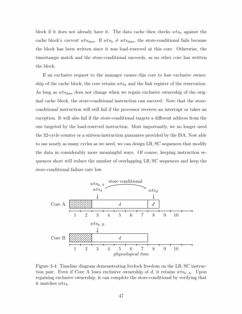
Figure 3-4: Timeline diagram demonstrating livelock freedom on the LR/SC instruc-tion pair. Even if Core A loses exclusive ownership of d, it retains wts
lr, A
. Uponregaining exclusive ownership, it can complete the store-conditional by verifying thatit matches wts
d
.
47
Figure 3-4 shows an LR/SC instruction happening on a timeline diagram. Core
A successfully writes d0 because the wts of the cache block still matches the wtslr, A
saved by the load-reserved instruction. This implies that the cache block data has not
changed. Upon gaining exclusive ownership, Core B will detect the altered wts, and
fail the store-conditional instruction. This scheme elegantly avoids livelock because a
cache block’s wts persists through invalidations and only changes when a core changes
the data at the cache block. Therefore, a write will eventually succeed at one of the
cores.
3.3 Atomic Memory Operations
The NYU Ultracomputer introduced atomic memory operations (AMOs), described
then as read-modify-write (RMW) instructions [26]. The Wisconsin Multicube ar-
chitecture implemented hardware fetch-and-Phi (fetch-and-�) operations [27]. These
instructions write to memory the result of an operation with a register as one of its
operands and the original value that memory location as the other. Phi (�) repre-
sents the operation – addition, bitwise and, maximum, and so on – to be performed
on the value in memory and a register operand. The cache returns the previous value
of the memory location to the core.
In a system that supports remote AMOs, the manager uses its own arithmetic logic
unit (ALU) to compute the result of an atomic memory operation. This approach
eliminates the need to transfer cache block data, although the manager should ensure
that no clients cache the block to reduce potential invalidations. Local atomic memory
operations will require the cache block to be present at the L1 cache, and can be
implemented by temporarily preventing cache invalidations.
When a remote AMO occurs on a system with a directory-based coherence proto-
col, it may have to invalidate current sharers. On a system that implements Tardis,
AMOs do not need to invalidate sharers, reducing invalidation traffic. The last-level
cache automatically updates wts and rts as if it were a client performing a store. An
L1 data cache that implements local AMOs takes advantage of a cache block in the
48
exclusive state, and does not differ from the baseline implementation of AMOs.
Summary
We gently altered three classes of atomic instructions to take advantage of physio-
logical time. In doing so, we mitigated the ABA problem for the compare-and-swap
instruction. With livelock freedom, we make the LR/SC instruction pair simpler to
implement and easier to use. It could become feasible to modify larger data struc-
tures without excessive spinning. We also used physiological time to reduce cache
block invalidations when performing remote AMOs. Fast, simple, and useful atomic
instructions form the basis for constructing high-performance synchronization primi-
tives, which we cover in the next chapter.
49

50
Chapter 4
Synchronization
Synchronization primitives ensure that concurrent programs work correctly by pre-
venting unwanted concurrent accesses or by separating phases of computation. Many
efforts have tried to improve the ability to scale synchronization on multicore machines
[27, 28]. Locks prevent concurrent accesses to the same data by forcing serialization.
Barriers allow separately running threads of execution to meet at a single point in
physical time before proceeding onto the next phase of the program. We investigate
the implementation of locks and barriers with the atomic instructions we built in
Chapter 3. In this chapter, we refer to units executing parts of the same concurrent
program as threads.
4.1 Locks
Mutual exclusion locks, or mutexes, prevent more than one thread from accessing a
critical section of code – a section of code only one thread may execute at a time.
Programmers want fast locks, so that threads contending for the lock do not take an
excessive amount of time to acquire the lock. They also expect locks to work fairly
– namely, if all threads that acquire the lock eventually release it, then all threads
should pass through the critical section.
Spin locks are amongst the simplest of locks. A core acquires the lock by setting a
lock bit, and unlocks it by clearing it. Figure 4-1 shows the source code for a spin lock
51
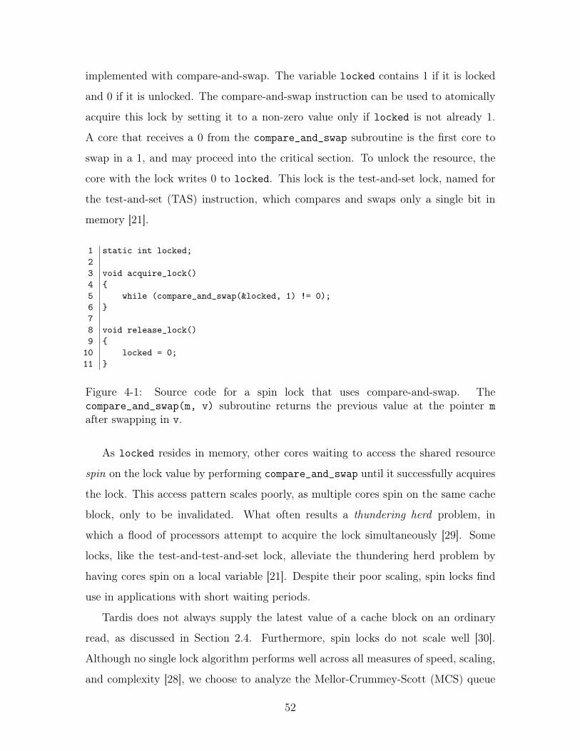
implemented with compare-and-swap. The variable locked contains 1 if it is locked
and 0 if it is unlocked. The compare-and-swap instruction can be used to atomically
acquire this lock by setting it to a non-zero value only if locked is not already 1.
A core that receives a 0 from the compare_and_swap subroutine is the first core to
swap in a 1, and may proceed into the critical section. To unlock the resource, the
core with the lock writes 0 to locked. This lock is the test-and-set lock, named for
the test-and-set (TAS) instruction, which compares and swaps only a single bit in
memory [21].
1 static int locked;23 void acquire_lock()4 {5 while (compare_and_swap(&locked, 1) != 0);6 }78 void release_lock()9 {
10 locked = 0;11 }
Figure 4-1: Source code for a spin lock that uses compare-and-swap. Thecompare_and_swap(m, v) subroutine returns the previous value at the pointer m
after swapping in v.
As locked resides in memory, other cores waiting to access the shared resource
spin on the lock value by performing compare_and_swap until it successfully acquires
the lock. This access pattern scales poorly, as multiple cores spin on the same cache
block, only to be invalidated. What often results a thundering herd problem, in
which a flood of processors attempt to acquire the lock simultaneously [29]. Some
locks, like the test-and-test-and-set lock, alleviate the thundering herd problem by
having cores spin on a local variable [21]. Despite their poor scaling, spin locks find
use in applications with short waiting periods.
Tardis does not always supply the latest value of a cache block on an ordinary
read, as discussed in Section 2.4. Furthermore, spin locks do not scale well [30].
Although no single lock algorithm performs well across all measures of speed, scaling,
and complexity [28], we choose to analyze the Mellor-Crummey-Scott (MCS) queue
52
lock because it reduces the number of cache invalidations to one per lock release
operation [31].
4.1.1 The Mellor-Crummey-Scott Queue Lock
The Mellor-Crummey-Scott (MCS) queue lock [30] forms a linked list of cores waiting
to access a locked resource. Each core maintains its own local lock and knows the
location of a global lock corresponding to that resource. The locks are queue nodes
(qnodes), data structures that store the current locked state and the pointer to the
next core waiting on the lock. Cores acquiring an already-locked lock append them-
selves to the tail of the linked list. The core with the lock releases the lock by writing
to a field that allows the next core in the linked list to proceed. Figure 4-3 shows C
code to acquire and release MCS locks. Because of its linked-list structure, and the
way that each core unlocks the next, the MCS lock is well-suited to implementation
on Tardis.
Figure 4-2 illustrates the basic operation of the MCS lock. Threads attempt
to acquire the lock by performing a fetch-and-set operation (or atomic swap) with
the global lock value, replacing it with a pointer to the thread’s my_lock struct. If
global_lock contained the null pointer, then the thread has successfully acquired
the lock (step 2). If the pointer was not null, then the lock has already been acquired
– the thread sets its own locked field to 1. Then, it sets the next field of the queue
node at the end of the last node in the queue to point to its my_lock struct (step 3).
A thread with the lock passes it to the next thread by following the next pointer to
the next thread’s my_lock struct and setting its locked field to 0 (step 4). (If it is
the last thread in the queue, it sets global_lock back to the null pointer.)
The Tardis implementation of the MCS lock requires modifications to load the
latest value of the mcs_lock struct members. In particular, the loops on lines 21 and
38 of Figure 4-3 must load the latest value of locked and next, respectively. We used
the load-reserved instruction to obtain exclusive ownership to read the latest value.
53
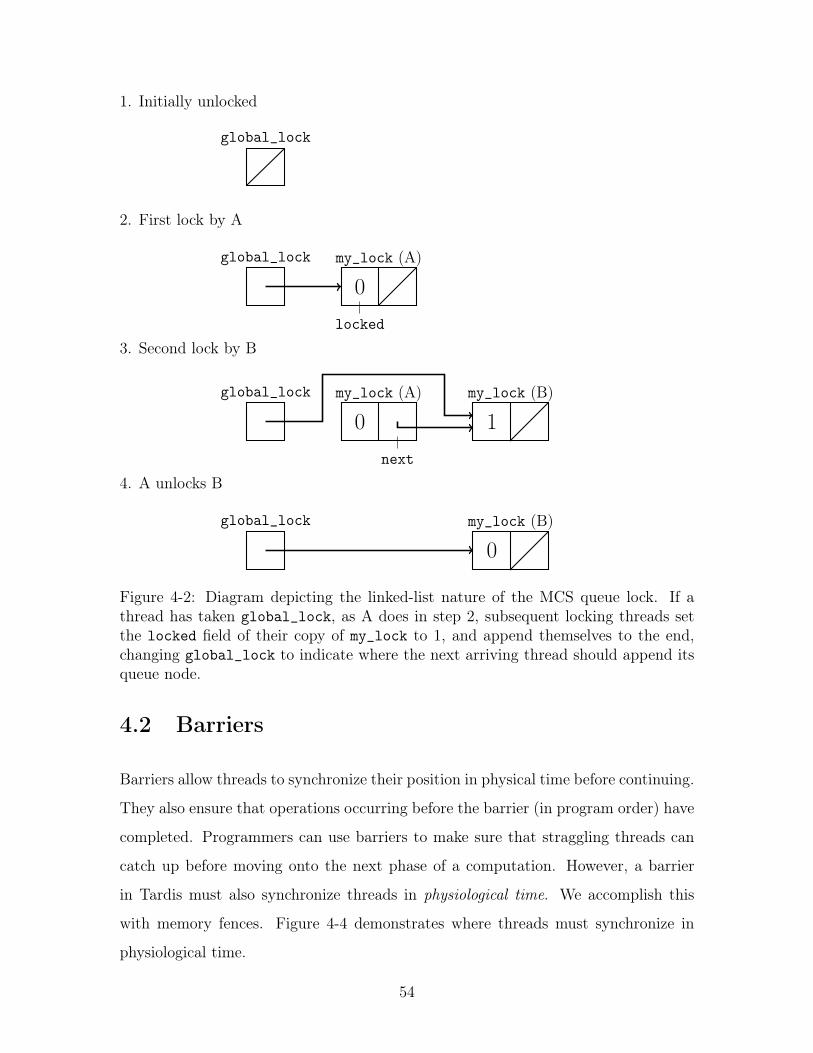
1. Initially unlocked
global_lock
2. First lock by A
global_lock
my_lock (A)
0locked
3. Second lock by B
global_lock
my_lock (A)
0next
my_lock (B)
1
4. A unlocks B
global_lock
my_lock (B)
0
Figure 4-2: Diagram depicting the linked-list nature of the MCS queue lock. If athread has taken global_lock, as A does in step 2, subsequent locking threads setthe locked field of their copy of my_lock to 1, and append themselves to the end,changing global_lock to indicate where the next arriving thread should append itsqueue node.
4.2 Barriers
Barriers allow threads to synchronize their position in physical time before continuing.
They also ensure that operations occurring before the barrier (in program order) have
completed. Programmers can use barriers to make sure that straggling threads can
catch up before moving onto the next phase of a computation. However, a barrier
in Tardis must also synchronize threads in physiological time. We accomplish this
with memory fences. Figure 4-4 demonstrates where threads must synchronize in
physiological time.
54
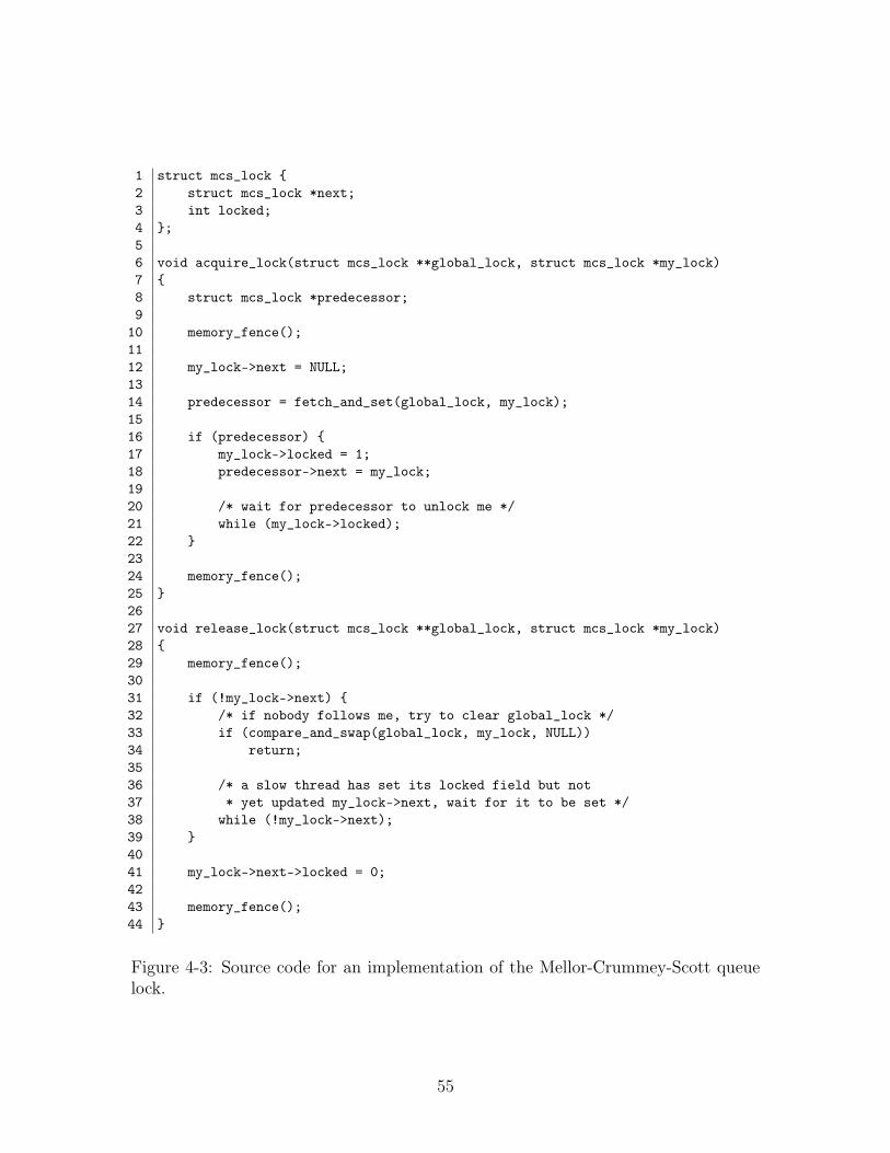
1 struct mcs_lock {2 struct mcs_lock *next;3 int locked;4 };56 void acquire_lock(struct mcs_lock **global_lock, struct mcs_lock *my_lock)7 {8 struct mcs_lock *predecessor;9
10 memory_fence();1112 my_lock->next = NULL;1314 predecessor = fetch_and_set(global_lock, my_lock);1516 if (predecessor) {17 my_lock->locked = 1;18 predecessor->next = my_lock;1920 /* wait for predecessor to unlock me */21 while (my_lock->locked);22 }2324 memory_fence();25 }2627 void release_lock(struct mcs_lock **global_lock, struct mcs_lock *my_lock)28 {29 memory_fence();3031 if (!my_lock->next) {32 /* if nobody follows me, try to clear global_lock */33 if (compare_and_swap(global_lock, my_lock, NULL))34 return;3536 /* a slow thread has set its locked field but not37 * yet updated my_lock->next, wait for it to be set */38 while (!my_lock->next);39 }4041 my_lock->next->locked = 0;4243 memory_fence();44 }
Figure 4-3: Source code for an implementation of the Mellor-Crummey-Scott queuelock.
55
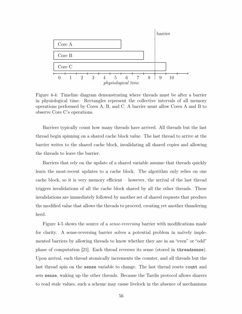
physiological time0 1 2 3 4 5 6 7 8 9 10
Core A
Core B
Core C
barrier
Figure 4-4: Timeline diagram demonstrating where threads must be after a barrierin physiological time. Rectangles represent the collective intervals of all memoryoperations performed by Cores A, B, and C. A barrier must allow Cores A and B toobserve Core C’s operations.
Barriers typically count how many threads have arrived. All threads but the last
thread begin spinning on a shared cache block value. The last thread to arrive at the
barrier writes to the shared cache block, invalidating all shared copies and allowing
the threads to leave the barrier.
Barriers that rely on the update of a shared variable assume that threads quickly
learn the most-recent updates to a cache block. The algorithm only relies on one
cache block, so it is very memory efficient – however, the arrival of the last thread
triggers invalidations of all the cache block shared by all the other threads. These
invalidations are immediately followed by another set of shared requests that produce
the modified value that allows the threads to proceed, creating yet another thundering
herd.
Figure 4-5 shows the source of a sense-reversing barrier with modifications made
for clarity. A sense-reversing barrier solves a potential problem in naïvely imple-
mented barriers by allowing threads to know whether they are in an “even” or “odd”
phase of computation [21]. Each thread reverses its sense (stored in threadsense).
Upon arrival, each thread atomically increments the counter, and all threads but the
last thread spin on the sense variable to change. The last thread resets count and
sets sense, waking up the other threads. Because the Tardis protocol allows sharers
to read stale values, such a scheme may cause livelock in the absence of mechanisms
56
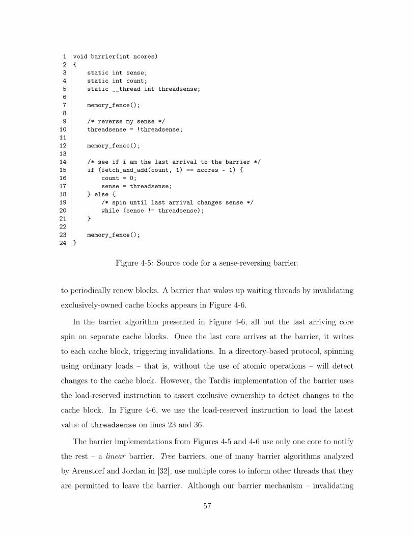
1 void barrier(int ncores)2 {3 static int sense;4 static int count;5 static __thread int threadsense;67 memory_fence();89 /* reverse my sense */
10 threadsense = !threadsense;1112 memory_fence();1314 /* see if i am the last arrival to the barrier */15 if (fetch_and_add(count, 1) == ncores - 1) {16 count = 0;17 sense = threadsense;18 } else {19 /* spin until last arrival changes sense */20 while (sense != threadsense);21 }2223 memory_fence();24 }
Figure 4-5: Source code for a sense-reversing barrier.
to periodically renew blocks. A barrier that wakes up waiting threads by invalidating
exclusively-owned cache blocks appears in Figure 4-6.
In the barrier algorithm presented in Figure 4-6, all but the last arriving core
spin on separate cache blocks. Once the last core arrives at the barrier, it writes
to each cache block, triggering invalidations. In a directory-based protocol, spinning
using ordinary loads – that is, without the use of atomic operations – will detect
changes to the cache block. However, the Tardis implementation of the barrier uses
the load-reserved instruction to assert exclusive ownership to detect changes to the
cache block. In Figure 4-6, we use the load-reserved instruction to load the latest
value of threadsense on lines 23 and 36.
The barrier implementations from Figures 4-5 and 4-6 use only one core to notify
the rest – a linear barrier. Tree barriers, one of many barrier algorithms analyzed
by Arenstorf and Jordan in [32], use multiple cores to inform other threads that they
are permitted to leave the barrier. Although our barrier mechanism – invalidating
57
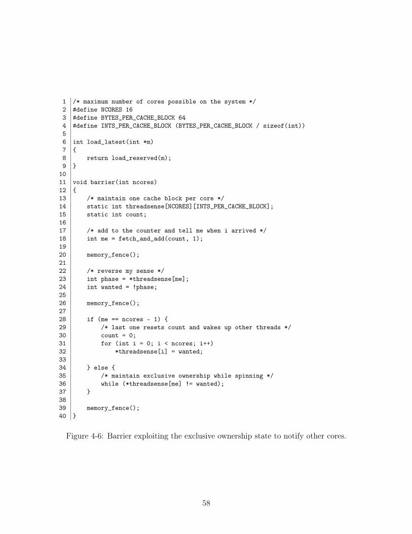
1 /* maximum number of cores possible on the system */2 #define NCORES 163 #define BYTES_PER_CACHE_BLOCK 644 #define INTS_PER_CACHE_BLOCK (BYTES_PER_CACHE_BLOCK / sizeof(int))56 int load_latest(int *m)7 {8 return load_reserved(m);9 }
1011 void barrier(int ncores)12 {13 /* maintain one cache block per core */14 static int threadsense[NCORES][INTS_PER_CACHE_BLOCK];15 static int count;1617 /* add to the counter and tell me when i arrived */18 int me = fetch_and_add(count, 1);1920 memory_fence();2122 /* reverse my sense */23 int phase = *threadsense[me];24 int wanted = !phase;2526 memory_fence();2728 if (me == ncores - 1) {29 /* last one resets count and wakes up other threads */30 count = 0;31 for (int i = 0; i < ncores; i++)32 *threadsense[i] = wanted;3334 } else {35 /* maintain exclusive ownership while spinning */36 while (*threadsense[me] != wanted);37 }3839 memory_fence();40 }
Figure 4-6: Barrier exploiting the exclusive ownership state to notify other cores.
58
exclusively-owned blocks – is implemented in a linear fashion, tree barriers can be
implemented analogously.
Summary
Today’s synchronization primitives assume that multicore systems have directory-
based cache coherence, but the Tardis protocols opens new possibilities for synchro-
nization that operate independently of physical time. In particular, timestamps may
obviate previously employed busy-waiting techniques. In this chapter, we reviewed
two of many possible synchronization primitives and how to build them on a system
implementing Tardis. In the next chapter, we discuss the hardware changes necessary
to run these modified synchronization primitives.
59

60
Chapter 5
Implementation
We implemented a cycle-level simulator for the Tardis cache coherence protocol – the
first we know of – on the Rocket Chip generator [15]. The Rocket Chip generator
generates a configurable system with Rocket cores connected to outer-level caches
and system environment (the “uncore”). The Rocket core is a six-stage, in-order
scalar RISC-V processor that supports a supervisor implementation as well as 64-
and 32-bit datapath widths. A four-stage pipelined non-blocking L1 data cache, the
HellaCache, connects Rocket to the outer levels of the memory hierarchy. The outer
memory hierarchies contain any number of L2 banks, which collectively serve as the
last-level cache; these banks interface with DRAMSim2, a cycle-level simulator of
main memory [33]. Rocket Chip is written in Chisel [34], a hardware design language
embedded in Scala that generates C++ for cycle-level emulation or Verilog for FPGA
synthesis and physical design.
In this chapter, we discuss our rationale for our design choices and the modifica-
tions required to the processor, network-on-chip, and coherence protocols needed to
implement Tardis.
5.1 Guiding Principles
In the interest of simplicity and elegance, we chose not to expose timestamps to the
programmer, so no instructions like “read timestamp“ or “write timestamp” exist. As
61
a result, we add no new instructions to the instruction set. Furthermore, we retain
binary compatibility. For the purposes of our evaluation, these features significantly
simplify our task.
Recall that a set of timestamps {tsmin
, tsmax
, tsrel
} should be kept per program to
prevent one program from prematurely expiring the cache blocks of other programs
by performing too many memory fence operations. Implementations that expose
timestamps to the programmer could rely on the operating system to modify the
timestamps of individual cores to limit interference by other programs. However, in-
troducing timestamps as additional microarchitectural state means that programmers
must save and restore to the stack in the event of a context switch. Restoring incor-
rect timestamps could result in a program observing the wrong values in memory –
something that would not occur in a conventional directory-based protocol. Because
we prohibit cores from directly changing timestamps through software, all threads run
with the same set of timestamps. Despite this limitation, our evaluation programs,
which run without operating system facilities, do not degrade in performance due to
this choice.
5.2 The RISC-V Rocket Microarchitecture
Implementing a client in the Tardis cache coherence protocol requires the addition
of three timestamp counters: tsrel
, tsmin
, and tsmax
. In a single-cycle core, the time-
stamps are always correct. Pipelining a processor, nowadays absolutely essential for
performance and efficiency, complicates the implementation of the Tardis timestamps.
5.2.1 Pipelining Timestamps
Pipelining processors increases performance by reducing the clock period, but it in-
troduces additional complexity because of the need for data bypasses and interlock-
ing. The timestamps needed by Tardis are part of the processor’s microarchitectural
state; although they are not directly accessible from software, the timestamps must
be pipelined through the processor. An instruction earlier in the pipeline could oth-
62
erwise be affected by modifications to these timestamps by instructions ahead in the
pipeline. Fortunately, release memory semantics allow operations to proceed out-of-
order in the absence of memory fences or acquire/release instructions. This choice of
memory model considerably simplifies Tardis-RC’s implementation, as Tardis-SC on
a pipelined processor would require bypassing timestamps.
The Rocket microarchitecture stalls the decode stage if there is a fence instruction
and remains stalled until the memory stage has completed all requests. Because we
have stored timestamps at the decode stage, it is unnecessary to bypass timestamps.
However, should timestamps be propagated into the execution units (such as in an
out-of-order core or an aggressively pipelined in-order processor), updates to tsmin
would need to be bypassed to the memory unit to preserve the relaxed consistency
model.
A processor’s timestamp counters only change when instructions commit, which
parallels the semantics of all other instructions. This means that if a core takes an
interrupt or encounters an exception, the instructions affected do not make updates to
the timestamp. Conveniently, this requirement aligns with typical instruction commit
semantics.
5.2.2 Extending the Memory Hierarchy
Many of the changes to needed to implement Tardis occur in the HellaCache and
the outer levels of the memory hierarchy. We extended the metadata arrays in the
HellaCache and the L2 to support the storage of the wts and rts timestamps. We
extended the cache coherence protocol abstraction layer to define the Tardis protocol,
which amounts to defining the effects of messages on the manager and client. Rec-
ognizing the diminished importance of leases and renewals in Tardis-RC, we set the
lease to a fixed value of 10.
In the baseline implementation, a counter in the HellaCache tracks the number
of cycles that have elapsed since the most recent load-reserved instruction. A store-
conditional will fail if this counter exceeds 32 cycles. However, as we demonstrated
in Section 3.2, the counter is not necessary; we eliminate the counter in the Tardis
63
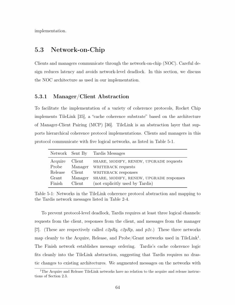
implementation.
5.3 Network-on-Chip
Clients and managers communicate through the network-on-chip (NOC). Careful de-
sign reduces latency and avoids network-level deadlock. In this section, we discuss
the NOC architecture as used in our implementation.
5.3.1 Manager/Client Abstraction
To facilitate the implementation of a variety of coherence protocols, Rocket Chip
implements TileLink [35], a “cache coherence substrate” based on the architecture
of Manager-Client Pairing (MCP) [36]. TileLink is an abstraction layer that sup-
ports hierarchical coherence protocol implementations. Clients and managers in this
protocol communicate with five logical networks, as listed in Table 5-1.
Network Sent By Tardis Messages
Acquire Client share, modify, renew, upgrade requestsProbe Manager writeback requestsRelease Client writeback responsesGrant Manager share, modify, renew, upgrade responsesFinish Client (not explicitly used by Tardis)
Table 5-1: Networks in the TileLink coherence protocol abstraction and mapping tothe Tardis network messages listed in Table 2-4.
To prevent protocol-level deadlock, Tardis requires at least three logical channels:
requests from the client, responses from the client, and messages from the manager
[7]. (These are respectively called c2pRq, c2pRp, and p2c.) These three networks
map cleanly to the Acquire, Release, and Probe/Grant networks used in TileLink1.
The Finish network establishes message ordering. Tardis’s cache coherence logic
fits cleanly into the TileLink abstraction, suggesting that Tardis requires no dras-
tic changes to existing architectures. We augmented messages on the networks with1The Acquire and Release TileLink networks have no relation to the acquire and release instruc-
tions of Section 2.3.
64

Network Sent By Timestamps
Acquire Client Client’s ptsProbe Manager noneRelease Client Cache block’s wts, rtsGrant Manager Cache block’s wts, rtsFinish Client none
Table 5-2: Timestamps required as part of a network message for an implementationof Tardis in the TileLink protocol.
Tardis’s timestamps, as listed in Table 5-2. Other than these modifications, Tardis’s
cache coherence logic required no major changes to the TileLink architecture.
5.3.2 Network Topology
In the original Rocket Chip generator design, crossbars connect clients and managers.
Each last-level cache bank requires one manager port on the crossbar, while each core
requires two client ports. For low core counts, a crossbar is an acceptable network-
on-chip. However, with many more cores, scaling the crossbar while maintaining
low latency becomes untenable because only one manager-client pair may hold the
network at a time. We chose to implement a mesh network to allow multiple messages
to be in flight at a modest cost in complexity. We anticipate our future massively
multicore systems will also use meshes.
Timestamps as wide as 64 bits may balloon the size of a message by 128 bits.
The impact of timestamp size can be mitigated with compression as proposed in [6].
Timestamps may also be sent as separate packets in the same message to reduce
network link width in exchange for a greater number of packets per message.
We selected the xy algorithm, a deterministic routing algorithm known for its
simplicity and deadlock freedom, to route packets on the network. Currently, all
packets carry header information, including the source and destination of a message,
but wormhole flow control [37] can reduce the area needed by the network-on-chip by
minimizing redundant routing information.
65
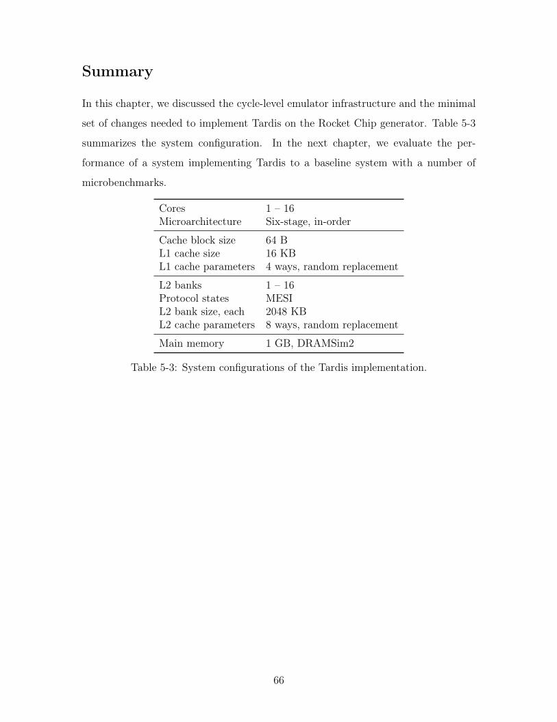
Summary
In this chapter, we discussed the cycle-level emulator infrastructure and the minimal
set of changes needed to implement Tardis on the Rocket Chip generator. Table 5-3
summarizes the system configuration. In the next chapter, we evaluate the per-
formance of a system implementing Tardis to a baseline system with a number of
microbenchmarks.
Cores 1 – 16Microarchitecture Six-stage, in-order
Cache block size 64 BL1 cache size 16 KBL1 cache parameters 4 ways, random replacement
L2 banks 1 – 16Protocol states MESIL2 bank size, each 2048 KBL2 cache parameters 8 ways, random replacement
Main memory 1 GB, DRAMSim2
Table 5-3: System configurations of the Tardis implementation.
66
Chapter 6
Evaluation
In this chapter, we evaluate the performance of our implementation of Tardis-RC
against a baseline implementation of a directory-based protocol in cycle-level simu-
lation. We sweep from systems with one core to sixteen cores. Limitations in the
simulator infrastructure made scaling systems to 32 cores and beyond impractical.
6.1 Atomic Instructions
We developed microbenchmarks to selectively exercise and evaluate the performance
of the load-reserved/store-conditional (LR/SC) pair and atomic memory operations
(AMOs). In these microbenchmarks, each core attempts to increment a counter using
the aforementioned instructions. All microbenchmarks follow the pattern in Figure 6-
1.
Compare-and-Swap
We do not implement or evaluate the performance of compare-and-swap (CAS), be-
cause the RISC-V architecture would require (1) substantial modifications to the
memory system and (2) a three-ported register file to read a memory address, the
comparison value, and the replacement value. Locking the bus from other cores, as
the x86 architecture does [23], is not feasible with a system with hundreds or thou-
67
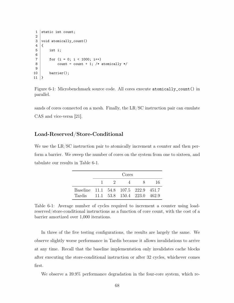
1 static int count;23 void atomically_count()4 {5 int i;67 for (i = 0; i < 1000; i++)8 count = count + 1; /* atomically */9
10 barrier();11 }
Figure 6-1: Microbenchmark source code. All cores execute atomically_count() inparallel.
sands of cores connected on a mesh. Finally, the LR/SC instruction pair can emulate
CAS and vice-versa [21].
Load-Reserved/Store-Conditional
We use the LR/SC instruction pair to atomically increment a counter and then per-
form a barrier. We sweep the number of cores on the system from one to sixteen, and
tabulate our results in Table 6-1.
Cores
1 2 4 8 16
Baseline 11.1 54.8 107.5 222.9 451.7Tardis 11.1 53.8 150.4 223.0 462.9
Table 6-1: Average number of cycles required to increment a counter using load-reserved/store-conditional instructions as a function of core count, with the cost of abarrier amortized over 1,000 iterations.
In three of the five testing configurations, the results are largely the same. We
observe slightly worse performance in Tardis because it allows invalidations to arrive
at any time. Recall that the baseline implementation only invalidates cache blocks
after executing the store-conditional instruction or after 32 cycles, whichever comes
first.
We observe a 39.9% performance degradation in the four-core system, which re-
68
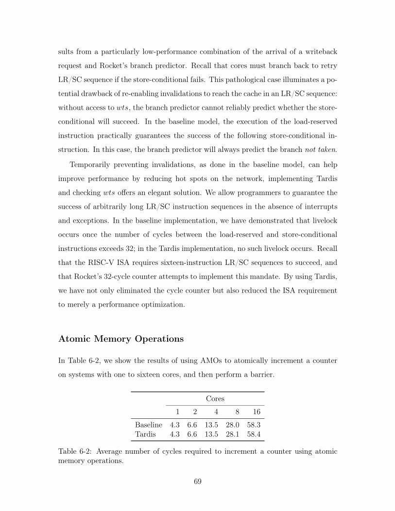
sults from a particularly low-performance combination of the arrival of a writeback
request and Rocket’s branch predictor. Recall that cores must branch back to retry
LR/SC sequence if the store-conditional fails. This pathological case illuminates a po-
tential drawback of re-enabling invalidations to reach the cache in an LR/SC sequence:
without access to wts, the branch predictor cannot reliably predict whether the store-
conditional will succeed. In the baseline model, the execution of the load-reserved
instruction practically guarantees the success of the following store-conditional in-
struction. In this case, the branch predictor will always predict the branch not taken.
Temporarily preventing invalidations, as done in the baseline model, can help
improve performance by reducing hot spots on the network, implementing Tardis
and checking wts offers an elegant solution. We allow programmers to guarantee the
success of arbitrarily long LR/SC instruction sequences in the absence of interrupts
and exceptions. In the baseline implementation, we have demonstrated that livelock
occurs once the number of cycles between the load-reserved and store-conditional
instructions exceeds 32; in the Tardis implementation, no such livelock occurs. Recall
that the RISC-V ISA requires sixteen-instruction LR/SC sequences to succeed, and
that Rocket’s 32-cycle counter attempts to implement this mandate. By using Tardis,
we have not only eliminated the cycle counter but also reduced the ISA requirement
to merely a performance optimization.
Atomic Memory Operations
In Table 6-2, we show the results of using AMOs to atomically increment a counter
on systems with one to sixteen cores, and then perform a barrier.
Cores
1 2 4 8 16
Baseline 4.3 6.6 13.5 28.0 58.3Tardis 4.3 6.6 13.5 28.1 58.4
Table 6-2: Average number of cycles required to increment a counter using atomicmemory operations.
69
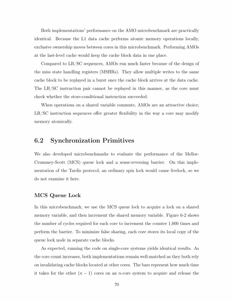
Both implementations’ performance on the AMO microbenchmark are practically
identical. Because the L1 data cache performs atomic memory operations locally,
exclusive ownership moves between cores in this microbenchmark. Performing AMOs
at the last-level cache would keep the cache block data in one place.
Compared to LR/SC sequences, AMOs run much faster because of the design of
the miss state handling registers (MSHRs). They allow multiple writes to the same
cache block to be replayed in a burst once the cache block arrives at the data cache.
The LR/SC instruction pair cannot be replayed in this manner, as the core must
check whether the store-conditional instruction succeeded.
When operations on a shared variable commute, AMOs are an attractive choice;
LR/SC instruction sequences offer greater flexibility in the way a core may modify
memory atomically.
6.2 Synchronization Primitives
We also developed microbenchmarks to evaluate the performance of the Mellor-
Crummey-Scott (MCS) queue lock and a sense-reversing barrier. On this imple-
mentation of the Tardis protocol, an ordinary spin lock would cause livelock, so we
do not examine it here.
MCS Queue Lock
In this microbenchmark, we use the MCS queue lock to acquire a lock on a shared
memory variable, and then increment the shared memory variable. Figure 6-2 shows
the number of cycles required for each core to increment the counter 1,000 times and
perform the barrier. To minimize false sharing, each core stores its local copy of the
queue lock node in separate cache blocks.
As expected, running the code on single-core systems yields identical results. As
the core count increases, both implementations remain well-matched as they both rely
on invalidating cache blocks located at other cores. The bars represent how much time
it takes for the other (n � 1) cores on an n-core system to acquire and release the
70
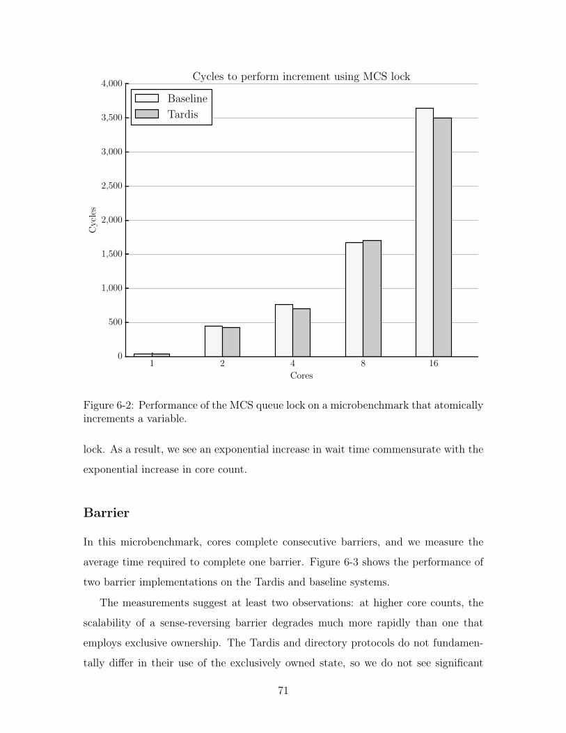
1 2 4 8 16
Cores
0
500
1,000
1,500
2,000
2,500
3,000
3,500
4,000
Cycles
Cycles to perform increment using MCS lock
Baseline
Tardis
Figure 6-2: Performance of the MCS queue lock on a microbenchmark that atomicallyincrements a variable.
lock. As a result, we see an exponential increase in wait time commensurate with the
exponential increase in core count.
Barrier
In this microbenchmark, cores complete consecutive barriers, and we measure the
average time required to complete one barrier. Figure 6-3 shows the performance of
two barrier implementations on the Tardis and baseline systems.
The measurements suggest at least two observations: at higher core counts, the
scalability of a sense-reversing barrier degrades much more rapidly than one that
employs exclusive ownership. The Tardis and directory protocols do not fundamen-
tally differ in their use of the exclusively owned state, so we do not see significant
71
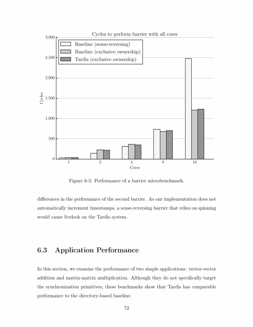
1 2 4 8 16
Cores
0
500
1,000
1,500
2,000
2,500
3,000
Cycles
Cycles to perform barrier with all cores
Baseline (sense-reversing)
Baseline (exclusive ownership)
Tardis (exclusive ownership)
Figure 6-3: Performance of a barrier microbenchmark.
differences in the performance of the second barrier. As our implementation does not
automatically increment timestamps, a sense-reversing barrier that relies on spinning
would cause livelock on the Tardis system.
6.3 Application Performance
In this section, we examine the performance of two simple applications: vector-vector
addition and matrix-matrix multiplication. Although they do not specifically target
the synchronization primitives, these benchmarks show that Tardis has comparable
performance to the directory-based baseline.
72
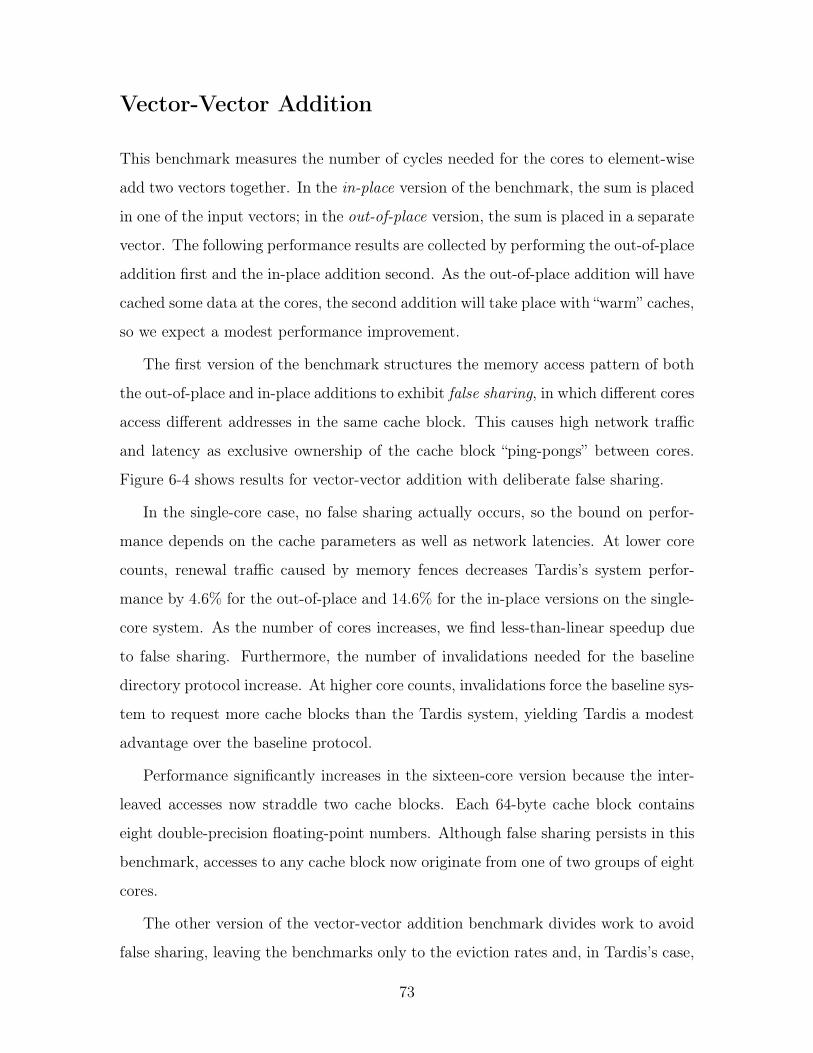
Vector-Vector Addition
This benchmark measures the number of cycles needed for the cores to element-wise
add two vectors together. In the in-place version of the benchmark, the sum is placed
in one of the input vectors; in the out-of-place version, the sum is placed in a separate
vector. The following performance results are collected by performing the out-of-place
addition first and the in-place addition second. As the out-of-place addition will have
cached some data at the cores, the second addition will take place with “warm” caches,
so we expect a modest performance improvement.
The first version of the benchmark structures the memory access pattern of both
the out-of-place and in-place additions to exhibit false sharing, in which different cores
access different addresses in the same cache block. This causes high network traffic
and latency as exclusive ownership of the cache block “ping-pongs” between cores.
Figure 6-4 shows results for vector-vector addition with deliberate false sharing.
In the single-core case, no false sharing actually occurs, so the bound on perfor-
mance depends on the cache parameters as well as network latencies. At lower core
counts, renewal traffic caused by memory fences decreases Tardis’s system perfor-
mance by 4.6% for the out-of-place and 14.6% for the in-place versions on the single-
core system. As the number of cores increases, we find less-than-linear speedup due
to false sharing. Furthermore, the number of invalidations needed for the baseline
directory protocol increase. At higher core counts, invalidations force the baseline sys-
tem to request more cache blocks than the Tardis system, yielding Tardis a modest
advantage over the baseline protocol.
Performance significantly increases in the sixteen-core version because the inter-
leaved accesses now straddle two cache blocks. Each 64-byte cache block contains
eight double-precision floating-point numbers. Although false sharing persists in this
benchmark, accesses to any cache block now originate from one of two groups of eight
cores.
The other version of the vector-vector addition benchmark divides work to avoid
false sharing, leaving the benchmarks only to the eviction rates and, in Tardis’s case,
73
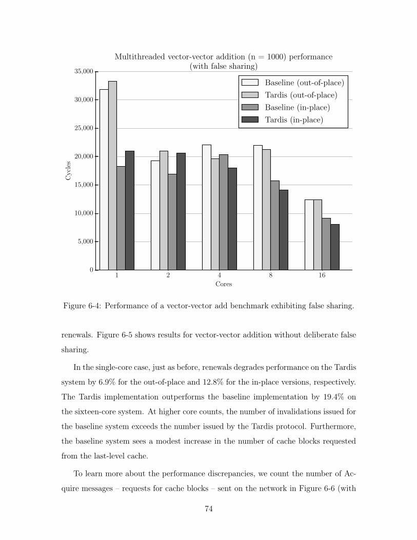
1 2 4 8 16
Cores
0
5,000
10,000
15,000
20,000
25,000
30,000
35,000
Cycles
Multithreaded vector-vector addition (n = 1000) performance
(with false sharing)
Baseline (out-of-place)
Tardis (out-of-place)
Baseline (in-place)
Tardis (in-place)
Figure 6-4: Performance of a vector-vector add benchmark exhibiting false sharing.
renewals. Figure 6-5 shows results for vector-vector addition without deliberate false
sharing.
In the single-core case, just as before, renewals degrades performance on the Tardis
system by 6.9% for the out-of-place and 12.8% for the in-place versions, respectively.
The Tardis implementation outperforms the baseline implementation by 19.4% on
the sixteen-core system. At higher core counts, the number of invalidations issued for
the baseline system exceeds the number issued by the Tardis protocol. Furthermore,
the baseline system sees a modest increase in the number of cache blocks requested
from the last-level cache.
To learn more about the performance discrepancies, we count the number of Ac-
quire messages – requests for cache blocks – sent on the network in Figure 6-6 (with
74
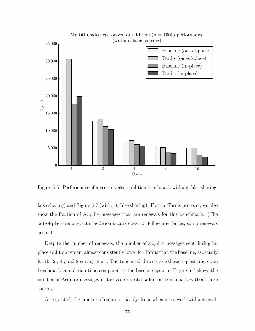
1 2 4 8 16
Cores
0
5,000
10,000
15,000
20,000
25,000
30,000
35,000
Cycles
Multithreaded vector-vector addition (n = 1000) performance
(without false sharing)
Baseline (out-of-place)
Tardis (out-of-place)
Baseline (in-place)
Tardis (in-place)
Figure 6-5: Performance of a vector-vector addition benchmark without false sharing.
false sharing) and Figure 6-7 (without false sharing). For the Tardis protocol, we also
show the fraction of Acquire messages that are renewals for this benchmark. (The
out-of-place vector-vector addition occurs does not follow any fences, so no renewals
occur.)
Despite the number of renewals, the number of acquire messages sent during in-
place addition remain almost consistently lower for Tardis than the baseline, especially
for the 2-, 4-, and 8-core systems. The time needed to service these requests increases
benchmark completion time compared to the baseline system. Figure 6-7 shows the
number of Acquire messages in the vector-vector addition benchmark without false
sharing.
As expected, the number of requests sharply drops when cores work without inval-
75
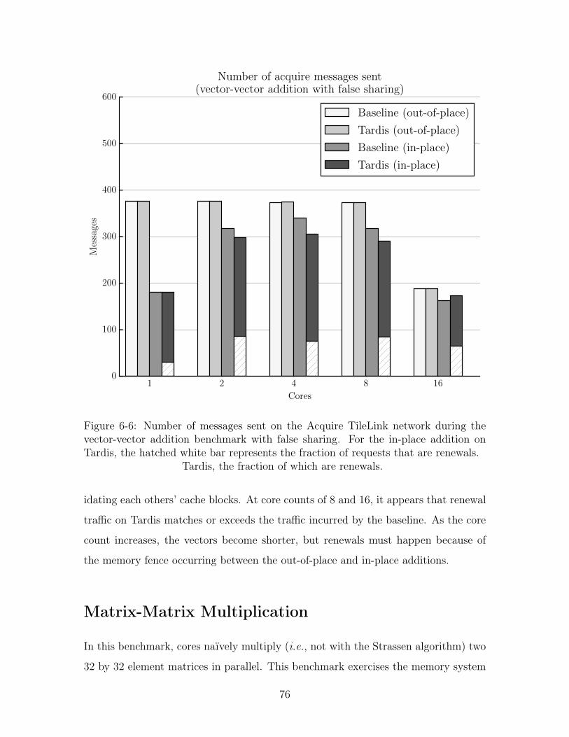
1 2 4 8 16
Cores
0
100
200
300
400
500
600
Messages
Number of acquire messages sent
(vector-vector addition with false sharing)
Baseline (out-of-place)
Tardis (out-of-place)
Baseline (in-place)
Tardis (in-place)
Figure 6-6: Number of messages sent on the Acquire TileLink network during thevector-vector addition benchmark with false sharing. For the in-place addition onTardis, the hatched white bar represents the fraction of requests that are renewals.
Tardis, the fraction of which are renewals.
idating each others’ cache blocks. At core counts of 8 and 16, it appears that renewal
traffic on Tardis matches or exceeds the traffic incurred by the baseline. As the core
count increases, the vectors become shorter, but renewals must happen because of
the memory fence occurring between the out-of-place and in-place additions.
Matrix-Matrix Multiplication
In this benchmark, cores naïvely multiply (i.e., not with the Strassen algorithm) two
32 by 32 element matrices in parallel. This benchmark exercises the memory system
76
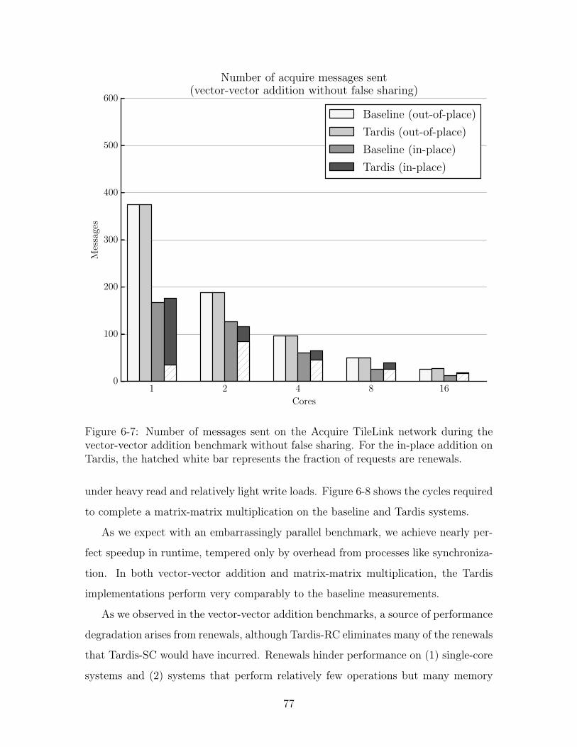
1 2 4 8 16
Cores
0
100
200
300
400
500
600
Messages
Number of acquire messages sent
(vector-vector addition without false sharing)
Baseline (out-of-place)
Tardis (out-of-place)
Baseline (in-place)
Tardis (in-place)
Figure 6-7: Number of messages sent on the Acquire TileLink network during thevector-vector addition benchmark without false sharing. For the in-place addition onTardis, the hatched white bar represents the fraction of requests are renewals.
under heavy read and relatively light write loads. Figure 6-8 shows the cycles required
to complete a matrix-matrix multiplication on the baseline and Tardis systems.
As we expect with an embarrassingly parallel benchmark, we achieve nearly per-
fect speedup in runtime, tempered only by overhead from processes like synchroniza-
tion. In both vector-vector addition and matrix-matrix multiplication, the Tardis
implementations perform very comparably to the baseline measurements.
As we observed in the vector-vector addition benchmarks, a source of performance
degradation arises from renewals, although Tardis-RC eliminates many of the renewals
that Tardis-SC would have incurred. Renewals hinder performance on (1) single-core
systems and (2) systems that perform relatively few operations but many memory
77
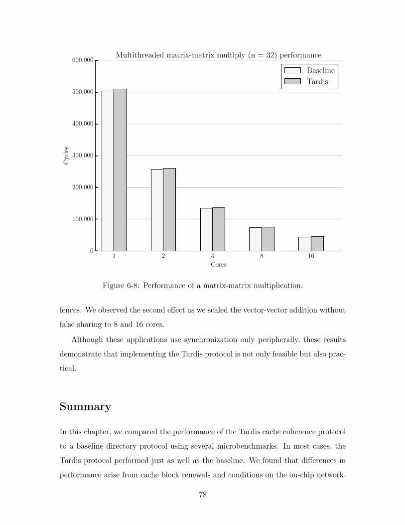
1 2 4 8 16
Cores
0
100,000
200,000
300,000
400,000
500,000
600,000
Cycles
Multithreaded matrix-matrix multiply (n = 32) performance
Baseline
Tardis
Figure 6-8: Performance of a matrix-matrix multiplication.
fences. We observed the second effect as we scaled the vector-vector addition without
false sharing to 8 and 16 cores.
Although these applications use synchronization only peripherally, these results
demonstrate that implementing the Tardis protocol is not only feasible but also prac-
tical.
Summary
In this chapter, we compared the performance of the Tardis cache coherence protocol
to a baseline directory protocol using several microbenchmarks. In most cases, the
Tardis protocol performed just as well as the baseline. We found that differences in
performance arise from cache block renewals and conditions on the on-chip network.
78
Despite the need for renewals in our applications, we saw that renewals become less
relevant in hampering overall protocol performance. We also find that renewals, once
a significant consideration in Tardis-SC, become diminished in relevance in Tardis-RC.
This evaluation yields many insights that can steer future inquiries into timestamp-
based coherence protocols.
79

80
Chapter 7
Conclusion
This thesis examined Tardis in sequentially-consistent and release-consistent variants.
We devised new atomic instructions to take advantage of Tardis’s timestamps and
used them to construct commonly-used synchronization primitives. We demonstrated
that the Tardis implementations perform nearly as well as our baseline system.
7.1 Future Work
We have only taken a glimpse at the unique possibilities offered by timestamp-based
cache coherence protocols like Tardis, and there is plenty of room for future work.
The Tardis invariant links the write timestamp to the value of the data. In this
thesis, we used it to eliminate the ABA problem in compare-and-swap and the livelock
problem in load-reserved/store-conditional sequences. Linking physiological time to
data will yield yet more innovation.
Currently, the only way to obtain the latest value of data in a cache is to load
it in the exclusive state (accomplished in our implementation with the load-reserved
instruction). We hope to find other ways of explicitly loading the latest value of a
cache block while minimizing cache invalidations. Ideally, we would establish some
mechanism to notify cores of an updated value and allow them to sleep or yield to
the operating system to schedule another process.
The prototype implementation has several shortcomings that hinder its practical-
81
ity. In each core, fully implementing the finer-grained timestamps – wtsmin
, wtsmax
,
rtsmin
, and rtsmax
in lieu of tsmin
and tsmax
– would align Rocket’s microarchitecture
to fully exploit the relaxations allowed by release consistency, but Rocket would also
need to be extended to make full use of these features.
Currently, all clients and managers have a mesh node on the network. Each client
and manager has its own node on the mesh, which is somewhat sub-optimal. We plan
to move to a tiled architecture, in which each node contains a core, its L1 cache, and
slice of the last-level cache, to reduce the number of routers and nodes on the main
network. All packets on the network, regardless of overall message length, contain
routing header information. With wormhole routing, we can dispense with all but
one of the copies of the header, and subsequently narrow the networks. To reduce
network area, we may merge logical networks which see relatively little traffic, like
the Probe and Grant networks.
Our evaluation uses microbenchmarks to individually evaluate the performance of
atomic instructions and synchronization primitives. A logical extension is to diverse
applications that measure realistic uses of the instructions and primitives covered in
this thesis. Synchronization plays a crucial role in operating system performance, so
incorporating physiological time may yield performance and scalability benefits. Of
course, synchronization is not the only bottleneck – today’s programming paradigms
make deep-seated assumptions about the underlying system architecture. To take
advantage of Tardis’s properties, we should find algorithms best-suited for scaling to
systems with thousands of cores. For instance, lock-free algorithms can reduce the
waiting ordinarily incurred by conventional synchronization primitives.
Our immediate future work involves the extension of this work towards the con-
struction of a thousand-core system1 with logic distributed throughout several inter-
connected FPGAs. Accordingly, we will optimize our design for FPGA synthesis,
including the elimination of any critical paths in the design. We especially want to
optimize the network-on-chip, as we have yet to synthesize it. In particular, we would
1The system is tentatively named T-1000, the time-traveling antagonist in Terminator 2: Judg-
ment Day (1991).
82
like to demonstrate a minimum of additional complexity and modest area2 and power
requirements.
7.2 Concluding Remarks
We will need a variety of techniques to build computers that satisfy strict constraints
on performance, power, and complexity. Tardis removes a major impediment to the
scaling of multiprocessor systems. Some efforts can be devoted to increasing the
number of cores on a single die. Others can extend the ideas from Tardis to other
domains. We will need to rethink the way concurrent applications run today to meet
the demands of the future. It’s not just about time; it’s about physiological time.
2To prove that a system implementing Tardis is not bigger on the inside.
83

84
Bibliography
[1] J. L. Hennessy and D. A. Patterson, Computer Architecture: A QuantitativeApproach. Elsevier, 2011.
[2] E. Gardner, “What public disclosures has Intel made about Knights Landing?”November 2014. [Online]. Available: https://software.intel.com/en-us/articles/what-disclosures-has-intel-made-about-knights-landing
[3] D. Chaiken, J. Kubiatowicz, and A. Agarwal, “LimitLESS Directories: Ascalable cache coherence scheme,” SIGPLAN Not., vol. 26, no. 4, pp. 224–234,Apr. 1991. [Online]. Available: http://doi.acm.org/10.1145/106973.106995
[4] D. Chaiken, C. Fields, K. Kurihara, and A. Agarwal, “Directory-based cachecoherence in large-scale multiprocessors,” Computer, vol. 23, no. 6, pp. 49–58,June 1990.
[5] Y.-C. Maa, D. K. Pradhan, and D. Thiebaut, “Two economical directoryschemes for large-scale cache coherent multiprocessors,” SIGARCH Comput.Archit. News, vol. 19, no. 5, pp. 10–, Sep. 1991. [Online]. Available:http://doi.acm.org/10.1145/379189.379198
[6] X. Yu and S. Devadas, “Tardis: Time Traveling Coherence Algorithm forDistributed Shared Memory,” CoRR, vol. abs/1501.04504, 2015. [Online].Available: http://arxiv.org/abs/1501.04504
[7] X. Yu, M. Vijayaraghavan, and S. Devadas, “A proof of correctness for thetardis cache coherence protocol,” CoRR, vol. abs/1505.06459, 2015. [Online].Available: http://arxiv.org/abs/1505.06459
[8] J. Miller, H. Kasture, G. Kurian, C. Gruenwald, N. Beckmann, C. Celio,J. Eastep, and A. Agarwal, “Graphite: A distributed parallel simulator for mul-ticores,” in High Performance Computer Architecture (HPCA), 2010 IEEE 16thInternational Symposium on, Jan 2010, pp. 1–12.
[9] M. S. Papamarcos and J. H. Patel, “A low-overhead coherence solution for mul-tiprocessors with private cache memories,” in ACM SIGARCH Computer Archi-tecture News, vol. 12, no. 3. ACM, 1984, pp. 348–354.
[10] Doctor Who, “Blink,” episode 10, originally aired June 9, 2007.
85
[11] L. Lamport, “Time, clocks, and the ordering of events in a distributed system,”Commun. ACM, vol. 21, no. 7, pp. 558–565, Jul. 1978. [Online]. Available:http://doi.acm.org/10.1145/359545.359563
[12] ——, “How to make a multiprocessor computer that correctly executes multipro-cess programs,” Computers, IEEE Transactions on, vol. 100, no. 9, pp. 690–691,1979.
[13] K. Gharachorloo, D. Lenoski, J. Laudon, P. Gibbons, A. Gupta, andJ. Hennessy, “Memory consistency and event ordering in scalable shared-memorymultiprocessors,” in Proceedings of the 17th Annual International Symposium onComputer Architecture, ser. ISCA ’90. New York, NY, USA: ACM, 1990, pp.15–26. [Online]. Available: http://doi.acm.org/10.1145/325164.325102
[14] S. V. Adve and K. Gharachorloo, “Shared memory consistency models: a tuto-rial,” Computer, vol. 29, no. 12, pp. 66–76, Dec 1996.
[15] K. Asanović, R. Avizienis, J. Bachrach, S. Beamer, D. Biancolin, C. Celio,H. Cook, D. Dabbelt, J. Hauser, A. Izraelevitz, S. Karandikar, B. Keller, D. Kim,J. Koenig, Y. Lee, E. Love, M. Maas, A. Magyar, H. Mao, M. Moreto, A. Ou,D. A. Patterson, B. Richards, C. Schmidt, S. Twigg, H. Vo, and A. Waterman,“The Rocket Chip generator,” EECS Department, University of California,Berkeley, Tech. Rep. UCB/EECS-2016-17, Apr 2016. [Online]. Available:http://www.eecs.berkeley.edu/Pubs/TechRpts/2016/EECS-2016-17.html
[16] A. Waterman, “Design of the risc-v instruction set architecture,” Ph.D.dissertation, EECS Department, University of California, Berkeley, Jan2016. [Online]. Available: http://www.eecs.berkeley.edu/Pubs/TechRpts/2016/EECS-2016-1.html
[17] P. L. Reiher, J. S. Heidemann, D. Ratner, G. Skinner, and G. J. Popek, “Re-solving file conflicts in the Ficus file system,” in Summer USENIX Conference,Proceedings of the, June 1994, pp. 183–195.
[18] D. B. Terry, M. M. Theimer, K. Petersen, A. J. Demers, M. J. Spreitzer, andC. H. Hauser, “Managing update conflicts in Bayou, a weakly connected repli-cated storage system,” in ACM Symposium on Operating Systems Principles,Proceedings of the 15th, December 1995.
[19] P. Keleher, A. L. Cox, S. Dwarkadas, and W. Zwaenepoel, “Treadmarks: Dis-tributed shared memory on standard workstations and operating systems,” inUSENIX Winter, vol. 1994, 1994, pp. 23–36.
[20] J. C. Corbett, J. Dean, M. Epstein, A. Fikes, C. Frost, J. J. Furman, S. Ghe-mawat, A. Gubarev, C. Heiser, P. Hochschild et al., “Spanner: Google’s glob-ally distributed database,” ACM Transactions on Computer Systems (TOCS),vol. 31, no. 3, p. 8, 2013.
86
[21] M. Herlihy and N. Shavit, The Art of Multiprocessor Programming, RevisedReprint. Elsevier, 2012.
[22] R. P. Case and A. Padegs, “Architecture of the IBM System/370,”Commun. ACM, vol. 21, no. 1, pp. 73–96, Jan. 1978. [Online]. Available:http://doi.acm.org/10.1145/359327.359337
[23] Intel 64 and IA-32 Architectures Software Developer’s Manual. Intel Corpora-tion, April 2016, vol. 2 (2A, 2B & 2C).
[24] E. H. Jensen, G. W. Hagensen, and J. M. Broughton, “A new approach to exclu-sive data access in shared memory multiprocessors,” Technical Report UCRL-97663, Lawrence Livermore National Laboratory, Tech. Rep., 1987.
[25] S. Steely, S. Van Doren, and M. Sharma, “Livelock prevention by delayingsurrender of ownership upon intervening ownership request during load locked /store conditional atomic memory operation,” Oct. 5 2004, uS Patent 6,801,986.[Online]. Available: https://www.google.com/patents/US6801986
[26] C. P. Kruskal, L. Rudolph, and M. Snir, “Efficient synchronizationof multiprocessors with shared memory,” ACM Trans. Program. Lang.Syst., vol. 10, no. 4, pp. 579–601, Oct. 1988. [Online]. Available:http://doi.acm.org/10.1145/48022.48024
[27] J. R. Goodman, M. K. Vernon, and P. J. Woest, “Efficient synchronizationprimitives for large-scale cache-coherent multiprocessors,” in Proceedings ofthe Third International Conference on Architectural Support for ProgrammingLanguages and Operating Systems, ser. ASPLOS III. New York, NY, USA: ACM,1989, pp. 64–75. [Online]. Available: http://doi.acm.org/10.1145/70082.68188
[28] T. David, R. Guerraoui, and V. Trigonakis, “Everything you always wantedto know about synchronization but were afraid to ask,” in Proceedings ofthe Twenty-Fourth ACM Symposium on Operating Systems Principles, ser.SOSP ’13. New York, NY, USA: ACM, 2013, pp. 33–48. [Online]. Available:http://doi.acm.org/10.1145/2517349.2522714
[29] “The Jargon File,” version 4.4.7. [Online]. Available: http://www.catb.org/jargon/html/T/thundering-herd-problem.html
[30] J. M. Mellor-Crummey and M. L. Scott, “Algorithms for scalable synchronizationon shared-memory multiprocessors,” ACM Trans. Comput. Syst., vol. 9, no. 1,pp. 21–65, Feb. 1991. [Online]. Available: http://doi.acm.org/10.1145/103727.103729
[31] S. Boyd-Wickizer, M. F. Kaashoek, R. Morris, and N. Zeldovich, “Non-scalablelocks are dangerous,” in Proceedings of the Linux Symposium, 2012, pp. 119–130.
[32] N. S. Arenstorf and H. F. Jordan, “Comparing barrier algorithms,” Parallel Com-puting, vol. 12, no. 2, pp. 157–170, 1989.
87
[33] P. Rosenfeld, E. Cooper-Balis, and B. Jacob, “DRAMSim2: A cycle accuratememory system simulator,” IEEE Computer Architecture Letters, vol. 10, no. 1,pp. 16–19, Jan 2011.
[34] J. Bachrach, H. Vo, B. Richards, Y. Lee, A. Waterman, R. Avižienis,J. Wawrzynek, and K. Asanović, “Chisel: Constructing Hardware in a ScalaEmbedded Language,” in Proceedings of the 49th Annual Design AutomationConference. ACM, 2012, pp. 1216–1225.
[35] H. Cook, “TileLink 0.3.3 specification.” [Online]. Available: https://docs.google.com/document/d/1Iczcjigc-LUi8QmDPwnAu1kH4Rrt6Kqi1_EUaCrfrk8/pub
[36] J. G. Beu, M. C. Rosier, and T. M. Conte, “Manager-client pairing: a frame-work for implementing coherence hierarchies,” in Proceedings of the 44th AnnualIEEE/ACM International Symposium on Microarchitecture. ACM, 2011, pp.226–236.
[37] W. J. Dally and B. P. Towles, Principles and Practices of Interconnection Net-works. Elsevier, 2004.
88


![Vietnam at a glance [Minh Nguyen]](https://img.pdfslide.us/doc/110x75/548bdc37b47959e96d8b4811/vietnam-at-a-glance-minh-nguyen.jpg)