Embed Size (px)
Citation preview

Quality, Reliability Quality, Reliability and Trust in and Trust in SimulationSimulation
Quality, Reliability Quality, Reliability and Trust in and Trust in SimulationSimulation
© 2011 ANSYS, Inc. All rights reserved. 1 ANSYS, Inc. Proprietary© 2011 ANSYS, Inc. All rights reserved. 1 ANSYS, Inc. Proprietary
Phil StopfordPhil Stopford
ANSYS UKANSYS UK
Phil StopfordPhil Stopford
ANSYS UKANSYS UK
De Vere Milton Hill House
6th April 2011
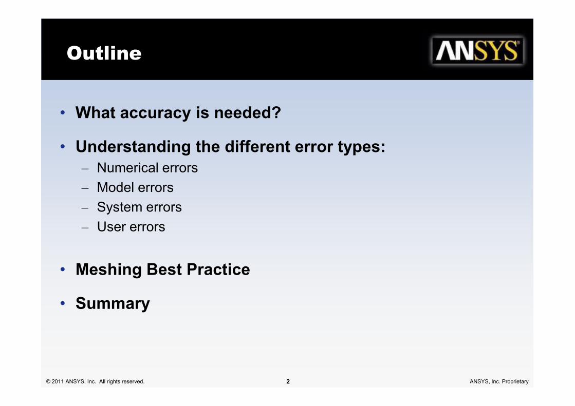
Outline
• What accuracy is needed?
• Understanding the different error types:
– Numerical errors
– Model errors
– System errors
© 2011 ANSYS, Inc. All rights reserved. 2 ANSYS, Inc. Proprietary
– System errors
– User errors
• Meshing Best Practice
• Summary

Motivation for Quality
• CAE results are used for many different stages of the design process:
– Design & optimization of components and machines
– Safety analyses
– Virtual prototypes
© 2011 ANSYS, Inc. All rights reserved. 3 ANSYS, Inc. Proprietary
• When undertaking a CAE model, consideration should be given to the
purpose of the work:
– What will the results be used for?
– What level of accuracy will be needed?

Different Sources of Error:
There are several different factors that combine to affect the
overall solution accuracy. In order of increasing magnitude:
– Round-off errors
• Computer is working to a certain numerical precision
– Iteration errors
• Difference between ‘converged’ solution and solution at
© 2011 ANSYS, Inc. All rights reserved. 4 ANSYS, Inc. Proprietary
iteration ‘n’
– Solution errors
• Difference between converged solution on current grid and
‘exact’ solution of model equations
– ‘Exact’ solution = Solution on infinitely fine grid
– Model errors
• Difference between ‘exact’ solution of model equations and
reality (data or analytic solution)

Round-Off Error
• Inaccuracies caused by machine round-off:
– Large differences in length scales
– Flow driven by small changes in pressure or density
– Large variable range
• Procedure:
© 2011 ANSYS, Inc. All rights reserved. 5 ANSYS, Inc. Proprietary
• Procedure:
– Define target variables
– Work with offset quantities (gauge pressure not absolute)
– Calculate with:
• Single-precision
• Double-precision
– Compare target variables

Iteration Error – Example
© 2011 ANSYS, Inc. All rights reserved. 6 ANSYS, Inc. Proprietary
R
(Re
sid
ua
l)

Iteration Error – Example
• Effect of difference Residual limits during convergence:
– 2D Compressor cascade
– 2nd order
Rmax = 1 × 10⁻³ Rmax = 1 × 10⁻⁴ Rmax = 1 × 10⁻⁵
© 2011 ANSYS, Inc. All rights reserved. 7 ANSYS, Inc. Proprietary
Change of Pressure Distribution

Iteration Error – Example
Relative error:
0.18% 0.01%
Isentr
opic
Effic
iency
Iteration errors:
Difference between
‘converged’ solution and
solution at iteration ‘n’
© 2011 ANSYS, Inc. All rights reserved. 8 ANSYS, Inc. Proprietary
Rmax=10-2
Iteration 35
Rmax=10-3
Iteration 59
Rmax=10-4
Iteration 132
Isentr
opic
Effic
iency
Convergence criterion
Iteration Number

Iteration Error - Best Practice
• Define target variables:
– Head rise
– Efficiency
– Mass flow rate
– D
• Select convergence criterion (e.g. residual norm)
© 2011 ANSYS, Inc. All rights reserved. 9 ANSYS, Inc. Proprietary
• Plot target variables as a function of convergence criterion
• Set convergence criterion such that value of target variable becomes
“independent” of convergence criterion
• Check convergence of global balances

Solution (or Discretisation) Error
• All discrete methods have solution errors:
– Finite volume methods
– Finite element methods
– Finite difference methods
– ...
e f f= −
© 2011 ANSYS, Inc. All rights reserved. 10 ANSYS, Inc. Proprietary
• Difference between solution on a given grid and ‘exact’ solution on
an infinitely fine grid
• Exact solution not available Discretisation error estimation
h h exe f f= −

Advection Schemes
1st Order Upwind
Scheme
β = 0
Flow is misaligned with
mesh
fφ
0Cφ 1Cφ0dr
© 2011 ANSYS, Inc. All rights reserved. 11 ANSYS, Inc. Proprietary
β = 0
2nd Order
Scheme
β=1.0
Theory
0
1
High
Resolution
Scheme

Discretisation Error Estimation
• Impinging jet flow with
heat transfer
• 2-D, axisymmetric
• Compared grids:
– 50 × 50 800 × 800 H
D D= 26.5mm or 101.6mm
© 2011 ANSYS, Inc. All rights reserved. 12 ANSYS, Inc. Proprietary
• SST turbulence model
• Advection schemes:
– 1st order upwind
– 2nd order upwind
• Target quantities:
– Heat transfer
– Maximum Nusselt number
r

Discretisation Error Estimation
Grid
Nu Error
1st order 2nd order 1st order 2nd order
50 × 50 190.175 176.981 22.1 % 13.6 %
100 × 100 170.230 163.793 9.3 % 5.1 %
© 2011 ANSYS, Inc. All rights reserved. 13 ANSYS, Inc. Proprietary
100 × 100 170.230 163.793 9.3 % 5.1 %
200 × 200 162.664 159.761 4.4 % 2.6 %
400 × 400 159.646 158.296 2.3 % 1.4 %
800 × 800 157.808 157.168 1.1% 0.7 %
∞ × ∞ 155.751 155.777

Discretisation Error Estimation
• Practical alternatives:
– Compare solutions obtained with different advection schemes
– Compare solutions at regional refined meshes
© 2011 ANSYS, Inc. All rights reserved. 14 ANSYS, Inc. Proprietary

Model Errors
• Inadequacies of (empirical) mathematical models:
– Basic equations (Euler vs. RANS, steady-state vs. unsteady-state, D)
– Turbulence models
– Combustion models
– Multiphase flow models
– D
© 2011 ANSYS, Inc. All rights reserved. 15 ANSYS, Inc. Proprietary
• Discrepancies between experimental data and calculations remain,
even after all numerical errors have become insignificant!

Model Error: Impinging Jet
• Results: H/D=2, Re=23,000
Nu* TKE*
KE RNG KΩ
© 2011 ANSYS, Inc. All rights reserved. 16 ANSYS, Inc. Proprietary
KE
RNG
KΩ
KE
RNG
KΩ
Nu* TKE*
Model error

Systematic Errors
• Discrepancies remain, even if numerical and model errors are insignificant
• ‘Systematic errors’:
– Approximations of:
• Geometry
• Component vs. machine
© 2011 ANSYS, Inc. All rights reserved. 17 ANSYS, Inc. Proprietary
• Component vs. machine
• Boundary conditions
• Fluid and material properties, D
• Try to ‘understand’ application and physics
• Document and defend assumptions!
• Uncertainty analysis
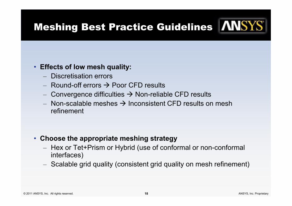
Meshing Best Practice Guidelines
• Effects of low mesh quality:
– Discretisation errors
– Round-off errors Poor CFD results
– Convergence difficulties Non-reliable CFD results
– Non-scalable meshes Inconsistent CFD results on mesh
© 2011 ANSYS, Inc. All rights reserved. 18 ANSYS, Inc. Proprietary
– Non-scalable meshes Inconsistent CFD results on mesh refinement
• Choose the appropriate meshing strategy
– Hex or Tet+Prism or Hybrid (use of conformal or non-conformal interfaces)
– Scalable grid quality (consistent grid quality on mesh refinement)
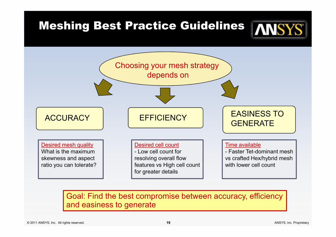
Meshing Best Practice Guidelines
EASINESS TO
Choosing your mesh strategy
depends on
ACCURACY EFFICIENCY
© 2011 ANSYS, Inc. All rights reserved. 19 ANSYS, Inc. Proprietary
GENERATEACCURACY EFFICIENCY
Desired mesh quality
What is the maximum
skewness and aspect
ratio you can tolerate?
Desired cell count
- Low cell count for
resolving overall flow
features vs High cell count
for greater details
Time available
- Faster Tet-dominant mesh
vs crafted Hex/hybrid mesh
with lower cell count
Goal: Find the best compromise between accuracy, efficiency and easiness to generate

Meshing: Capture Flow Physics
• Grid must be able to capture
important physics:
– Boundary layers
– Heat transfer
– Wakes, shock
– Flow gradients
• Boundary layers:
– Velocity and temperature
– 10-15 elements
– Expansion ratios:
≤ 1.2 D 1.3
– y+ ≈ 1 for heat transfer and
© 2011 ANSYS, Inc. All rights reserved. 20 ANSYS, Inc. Proprietary
– Flow gradients
• Tip: Sketch the solution you
expect before you start to mesh
– y+ ≈ 1 for heat transfer and
transition modeling

Mesh Quality
A good mesh depends on :
Cell not too distorted
Cell not too stretched
Good Not Good
© 2011 ANSYS, Inc. All rights reserved. 21 ANSYS, Inc. Proprietary
Smooth transition

Mesh Quality
• Grid generation:
– Scalable grids
– Skewness < 0.9 (accuracy, convergence)
– Aspect ratios < 100
– Expansion ratios < 1.5 D2
– Capture physics based on experience (shear layers, shocks)
Bad cells
© 2011 ANSYS, Inc. All rights reserved. 22 ANSYS, Inc. Proprietary
– Angle between grid face & flow vector
• Grid refinement:
– Manual, based on error estimate
– Automatic adaptive based on ‘error sensor’
Adaption
No bad cells

Mesh Quality
• Avoid sudden change in mesh density
© 2011 ANSYS, Inc. All rights reserved. 23 ANSYS, Inc. Proprietary
Not good Good
Hex
mesh
Tri
mesh
U=0.1
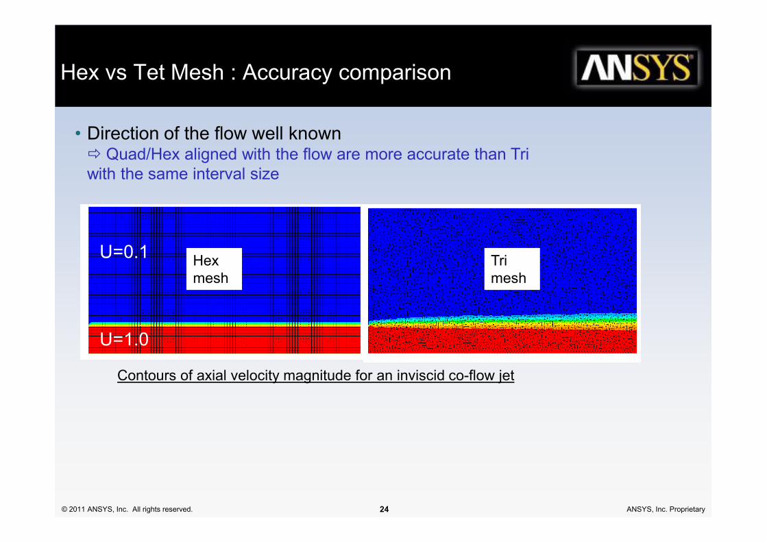
Hex vs Tet Mesh : Accuracy comparison
• Direction of the flow well known Quad/Hex aligned with the flow are more accurate than Tri
with the same interval size
© 2011 ANSYS, Inc. All rights reserved. 24 ANSYS, Inc. Proprietary
Contours of axial velocity magnitude for an inviscid co-flow jet
mesh mesh
U=1.0

U=0.1
Hex vs Tet Mesh : Accuracy comparison
• For complex flows without dominant flow direction, Quad and Hex
meshes lose their advantage Quad & Tri equivalent
qua
d tri
T =
1
T =
1
© 2011 ANSYS, Inc. All rights reserved. 25 ANSYS, Inc. Proprietary
U=1.0
d tri
T = 0
T =
1
U = V = 1.0 ,U = V = 1.0 ,T
= 1
U =
V =
1.0
,
U =
V =
1.0
,
T = 0
Contours of temperature for inviscid flow

Summary
• Try to ‘understand’ application and physics of the application
• Compare accuracy expectations with assumptions
• Distinguish between numerical, model and other errors
• Document and defend assumptions
– Geometry
– Boundary conditions
© 2011 ANSYS, Inc. All rights reserved. 26 ANSYS, Inc. Proprietary
– Boundary conditions
– Flow regime (laminar, turbulent, steady-state, unsteady-state, D)
– Model selection (turbulence, D)
• Be aware of sources of systematic error, e.g.
– Approximations
– Data

Resources
• ERCOFTAC SIG: ‘Quantification of Uncertainty in CFD’
www.ercoftac.org
• Roache, P. J., Verification and Validation in Computational
Science and Engineering, Hermosa Publishers, 1998
© 2011 ANSYS, Inc. All rights reserved. 27 ANSYS, Inc. Proprietary
Science and Engineering, Hermosa Publishers, 1998
• ANSYS Best Practice Guidelines