Embed Size (px)
Citation preview
Quaality Man
nual
`
2 2012
QUALITY CONTROL MANUAL
Section : I Page : 1 of 1 Rev. : 1 Date : 21 / 10 / 2012
Project Services Company PSC (S.A.E.) Qarit Oraby, Desert Road, Amria, Alexandria, Egypt Phone : +2 03 4482 402 Fax : +2 03 449 9641 E-mail : [email protected] Web : www.psc-eg.com
Quality Control Manual Title Page
Edition : III
Revision : 1
Date: 21 / 10 / 2012
Copy No.
Controlled
Uncontrolled
QUALITY CONTROL MANUAL Section : II Page : 1 of 2 Rev. : 2 Date : 20 / 12 / 2012
Table of Contents
Edition: III
Table of Contents
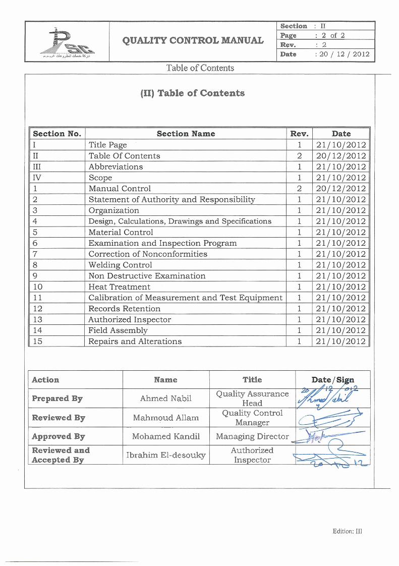
Table of Contents
++
Edition: 111
QUALITY CONTROL MANUAL
(11) Table of Contents
Section : I1 Page Rev.
:2of2 : 2
Date :20/ 121 2012
Title
Quality Assurance Head
Quality Control Manager
Managing Director C
Authorized Inspector
Action
Prepared By
Reviewed By
Approved By
Reviewed and Accepted By
Name
Ahmed Nabil
Mahmoud Allam
Mohamed Kandil
Ibrahim El-desouky
QUALITY CONTROL MANUAL Section : III Page : 1 of 3 Rev. : 1 Date : 21 / 10 / 2012
Abbreviations
Edition: III
Abbreviations
QUALITY CONTROL MANUAL Section : III Page : 2 of 3 Rev. : 1 Date : 21 / 10 / 2012
Abbreviations
Edition: III
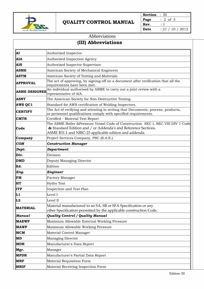
(III) Abbreviations
AI Authorized Inspector
AIA Authorized Inspection Agency
AIS Authorized Inspector Supervisor
ASME American Society of Mechanical Engineers
ASTM American Society of Testing and Materials
APPROVAL The act of approving, by signing-off on a document after verification that all the requirements have been met.
ASME DESIGNEE An individual authorised by ASME to carry out a joint review with a representative of AIA.
ASNT The American Society for Non-Destructive Testing.
AWS QC1 Standard for AWS certification of Welding Inspectors.
CERTIFY The Act of verifying and attesting in writing that Documents, process, products, or personnel qualifications comply with specified requirements.
CMTR Certified - Material Test Report
Code The ASME Boiler &Pressure Vessel Code of Construction SEC I, SEC VIII DIV 1 Code & Standard Edition and / or Addenda's and Reference Sections. ASME B31.1 and NBIC-23 applicable edition and addenda.
Company Project Services Company, PSC (S.A.E.)
COM Construction Manager Dept. Department Div. Division
DMD Deputy Managing Director
Ed. Edition
Eng. Engineer FM Factory Manager
HT Hydro Test
ITP Inspection and Test Plan
L1 Level I
L2 Level II
MATERIAL Material manufactured to an SA, SB or SFA Specification or any other Specification permitted by the applicable construction Code.
Manual Quality Control / Quality Manual MAEWP Maximum Allowable External Working Pressure
MAWP Maximum Allowable Working Pressure
MCM Material Control Manager
MD Managing Director
MDR Manufacturer's Data Report
Mgr. Manager
MPDR Manufacturer's Partial Data Report
MRF Material Requisition Form
MRIF Material Receiving Inspection Form
QUALITY CONTROL MANUAL Section : III Page : 3 of 3 Rev. : 1 Date : 21 / 10 / 2012
Abbreviations
Edition: III
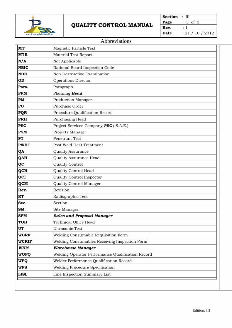
MT Magnetic Particle Test
MTR Material Test Report
N/A Not Applicable
NBIC National Board Inspection Code
NDE Non Destructive Examination
OD Operations Director
Para. Paragraph
PFM Planning Head
PM Production Manager
PO Purchase Order
PQR Procedure Qualification Record
PRH Purchasing Head
PSC Project Services Company PSC ( S.A.E.)
PSM Projects Manager
PT Penetrant Test
PWHT Post Weld Heat Treatment
QA Quality Assurance
QAH Quality Assurance Head
QC Quality Control
QCH Quality Control Head
QCI Quality Control Inspector
QCM Quality Control Manager
Rev. Revision
RT Radiographic Test
Sec. Section
SM Site Manager
SPM Sales and Proposal Manager TOH Technical Office Head
UT Ultrasonic Test
WCRF Welding Consumable Requisition Form
WCRIF Welding Consumables Receiving Inspection Form
WHM Warehouse Manager WOPQ Welding Operator Performance Qualification Record
WPQ Welder Performance Qualification Record
WPS Welding Procedure Specification
LISL Line Inspection Summary List
QUALITY CONTROL MANUAL Section : IV Page : 1 of 2 Rev. : 1 Date : 21 / 10 / 2012
Scope
Edition: III
Scope
QUALITY CONTROL MANUAL Section : IV Page : 2 of 2 Rev. : 1 Date : 21 / 10 / 2012
Scope
Edition: III
(IV) Scope
II.1 General
PSC has kept and maintained a Quality Control System which has been established to provide our custemors with boilers and boiler parts, boiler external piping, pressure vessels and pressure vessel parts (such as: towers and heat exchangers) required to be constructed in accordance with ASME Boiler and Pressure Vessel Code Section I, ASME B31.1, Section VIII Div.1, AWS, API, EN or other governing Codes or Standards (hereafter called Code). The Quality control system has been established to meet the requirements of ASME Code including design, material, fabrication and examination by PSC; and inspection by The Authorized Inspector (AI) for Power Boilers, Power Piping, Pressure Vessels and pressure vessels parts. The Quality control system has been established to cover activities in the shop and field sites.
This Manual also is applied to Metallic Repairs and/or Alterations at this Shop and extended for Field Repairs and/or Alterations controlled by this Shop” The scope covers the following: -
1. Construction and erection of boiler, boiler parts, pressure vessels, towers and heat exchangers in accordance with Code requirements.
2. Design and fabrication of all pressure vessel accessories, such as ladders, platforms…etc.
3. Field erection and testing of boilers and pressure vessels. 4. Design, fabrication, erection, testing and inspection of storage
tanks. 5. Repairs , alterations and re-rating of boilers, power piping and
pressure vessels to the requirements of NBIC NB23 and relevant construction code/standard
6. Design, fabrication and erection of steel structure, plate works and pressure/non pressure piping.
QUALITY CONTROL MANUAL Section : 1 Page : 1 of 3 Rev. : 2 Date : 20 / 12 / 2012
Manual Control
Edition: III
Manual Control
QUALITY CONTROL MANUAL Section : 1 Page : 2 of 3 Rev. : 2 Date : 20 / 12 / 2012
Manual Control
Edition: III
(1) Manual Control
1.1 This Manual shall be prepared by QAH, who collects the Manual sections prepared by each concerned personal (QCH, TOH & NDE Level III Examiner), reviewed by QCM, whilst the approval of such shall be granted by the Managing Director and reviewed and accepted by the AI of records. The QAH shall issue controlled copies of this approved Manual with transmittal advice in accordance with the list of Manual Holders Log (Exhibit No. (01-01)) maintained by him.
1.2 Each copy of this Manual will bear the same control number on its title page as shown on the List of Manual Holders Log, and the same will be done but on the back of each Manual pages. In case of electronic copies the control number will appear on the title page and it must be protected against changes and printing.
1.3 When new Code Edition or Addenda is issued; it shall be reviewed
by the concerned personal (QCH, TOH & NDE Level III Examiner) to determine the need for revisions required to the Quality Control Manual. The QAH shall document this review by his dated initials on a copy of the front page of the Edition/Addenda summary of changes page. This step shall also be recorded in record of Code Edition and Addenda review form (Exhibit (01-02)).
1.4 Revisions of the Manual – if needed- shall be prepared and
approved the same way as the original and then submitted to the AI of record for his review and acceptance prior to issue. However, revisions will be made by sections except for Exhibits.
1.5 Revisions of the Quality Control Manual are distributed to the List of Manual Holders Log using the Manual Holders Log within six months of Code Edition/Addenda issue date
1.6 Revisions are indicated in the corresponding pages by bold &
QUALITY CONTROL MANUAL Section : 1 Page : 3 of 3 Rev. : 2 Date : 20 / 12 / 2012
Manual Control
Edition: III
italic font of the revised text. Only the latest revision will be indicated.
1.7 Revised sections and Ehibits of the Manual are issued,
distributed and controlled by the QAH in the same manner as stated through Para. 1.1 And 1.2 of this Section.
1.8 Revised Exhibits pages are issued individually with a revised List
of Exhibits Exhibit No. (1-03) by QAH.
1.9 QCM may, at his discretion advance the edition level of the Manual at which time all revision status of all sections shall revert to zero. However, exhibits revision numbers shall remain with the same revision status.
1.10 Uncontrolled copies of the Manual may be distributed to parties
outside PSC. However, there is no need to distribute a new un-controlled copies or withdraw the old revisions of the uncontrolled copies when the Manual is updated.
1.11 In case change to the QC Manual are requested by the AI of an AIA other than that of Record, all such changes shall be represented by the Quality Control Manager to the AI of the AIA of Record for his review and acceptance prior to revision of the Manual and its implementation.
1.12 The Quality Control Manual is issued in English Language only.
Work Instructions may be issued in both English and Arabic Languages, and in case of conflict between languages, the English text shall govern.
1.13 One master copy of earlier revision of the Manual marked supereeded shall be retained by QAH for minimum 3 years.
1.14 QAH is responsible to insure that revised copies are retuned and destroyed.
QUALITY CONTROL MANUAL Section : 2 Page : 1 of 2 Rev. : 1 Date : 21 / 10 / 2012
Statement of Authority and Responsibility
Edition: III
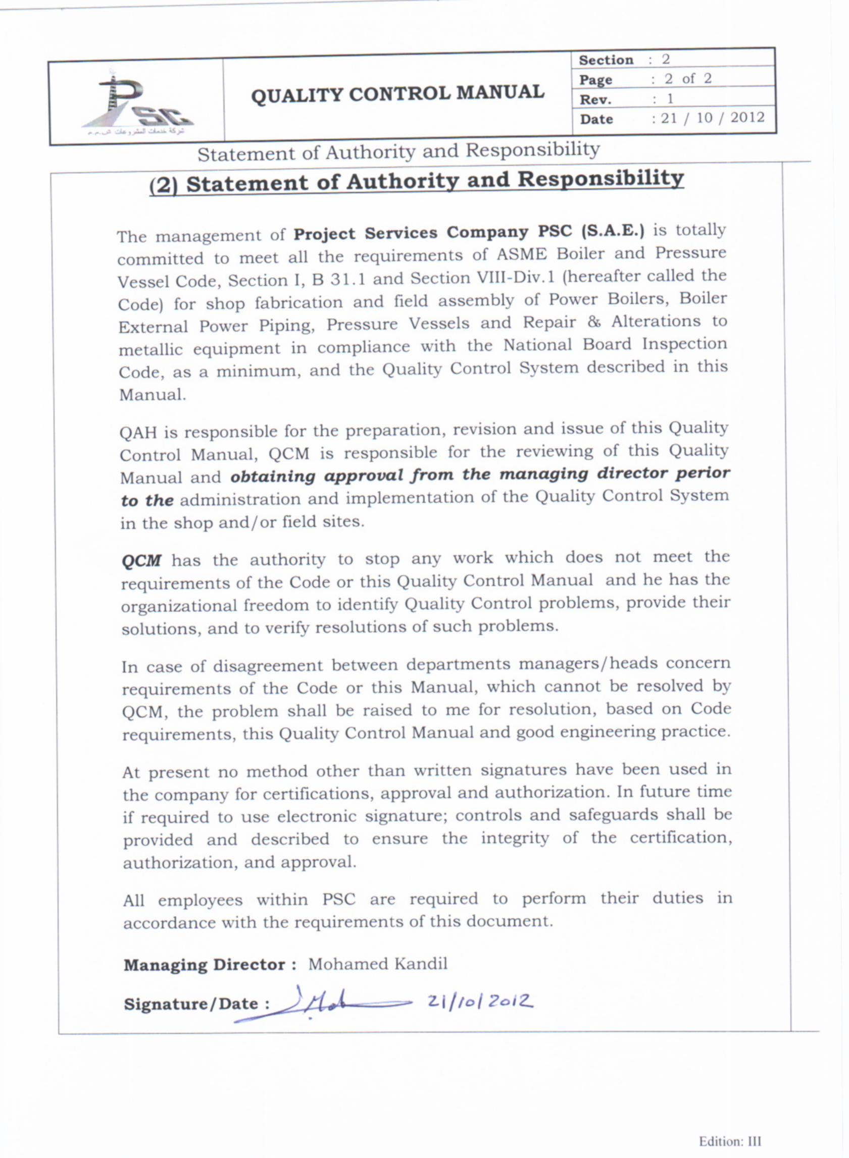
Statement of Authority and Responsibility

QUALITY CONTROL MANUAL Section : 3 Page : 1 of 6 Rev. : 1 Date : 21 / 10 / 2012
Organization
Edition: III
Organization
QUALITY CONTROL MANUAL Section : 3 Page : 2 of 6 Rev. : 1 Date : 21 / 10 / 2012
Organization
Edition: III
(3) Organization
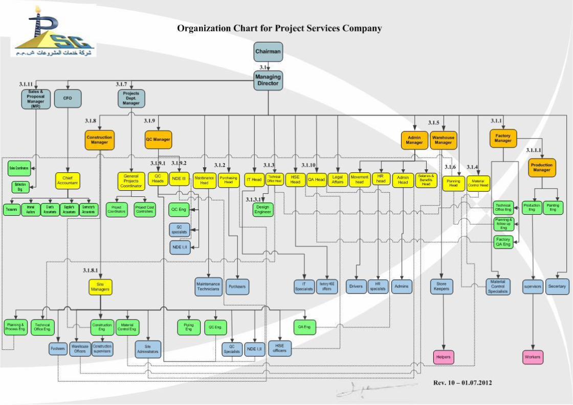
3.0 Organization of PSC The Organization Chart of PSC is attached to this Section.
3.1 Managing Director. (MD)
MD is the responsible person in PSC for all administrative issues and
operations activities within the company scope of works. He is responsible
for monitoring the performance of the department’s heads and managers,
and is responsible to the client for initiating any project and related action,
which is outside of head’s and manager's responsibilities.
MD is responsible for the approval of this QC Manual.
His staff consists of :-
3.1.1 Factory Manager. (FM)
He reports directly to MD. He is responsible for managing all activities and operations at PSC Workshop.
3.1.1.1 Production Manager. (PM)
He reports directly to Factory Manager. He is responsible for production activities according to design instruction, procedures and drawings at PSC Workshop. He will liaise with QCM during production in matters relating to inspection, testing, examinations and Quality Control.
3.1.2 Purchasing Head. (PRH)
He reports directly to MD He is responsible for following up of purchasing all Code materials according to Material Requisition Form (Exhibit No. 04-01), upon review by QCM and approval by TOH He is also responsible for the time of material arrival to be suitable with project schedule.
QUALITY CONTROL MANUAL Section : 3 Page : 3 of 6 Rev. : 1 Date : 21 / 10 / 2012
Organization
Edition: III
3.1.3 Technical Office Head. (TOH)
He Reports directly to MD. He is responsible for the Engineering and Design of Power Boilers, Boiler External Piping, and Pressure Vessels built to ASME Code Section I, B31.1, and Section VIII-Div.1, including approval of drawings to show the details of the construction of the Vessel, calculations, to support the design and specifications to show how these vessels comply with the applicable Code Section. He is responsible to manage Engineering and Design documents' transmission (new issues as well as revised issues) and to arrange with sales department for assigning a job number for each order of a Code item. He is also responsible for all engineering activities related to other Construction Codes and re-rating, alteration and repairs in according to NBIC NB 23. The scope of his responsibility covers both PSC work shop and sites controlled by it.
3.1.3.1 Design Engineer The Design Engineer reports directly to the TOH and is responsible for
preparation of design drawings, calculations and Material Requisitions of Code items being manufactured by the Company as well as repairs and alternations in according to NBIC NB 23.
3.1.4 Material Control Head. (MCH)
He reports directly to MD. He provides instructions for material controllers to control the receiving, storage, preservation, issuing, scrap,...etc related to all Code section materials, except welding consumables.
3.1.5 Warehouse Manager (WHM)
He reports directly to MD. He provides instructions for Warehouse Keeper to arrange the work of the warehouse (Receiving, storage, preservation, issuing, scrap,...etc). for all other materials and welding consumables not included in the scope of Material Control Head.
3.1.6 Planning Head (PFH)
He reports directly to MD. He will define for each contract the following… a) Fabrication Schedule of assigned work. b) Preparation of Resource Plan (Material - Labourers - Machines) and
resources activity location. c) Following-up of all activities. d) Progress Reports (Daily - Weekly - Monthly).
QUALITY CONTROL MANUAL Section : 3 Page : 4 of 6 Rev. : 1 Date : 21 / 10 / 2012
Organization
Edition: III
3.1.7 Projects Dept. Manager. (PSM)
He reports directly to MD. He is responsible for managing projects coordination, contract administration and cost control activities in both work shop and field sites.
3.1.8 Construction Manager. (COM)
He reports directly to MD. He is responsible for managing project activities and all operations at field sites.
3.1.8.1 Site Manager. (SM) He reports directly to Construction Manager and he is responsible for the site activities according to design instructions, procedures and drawings. He will liaise with QCM during Construction in matters relating to Inspection, Testing, Examination and Quality Control. It is the responsibility of Site Manager to ensure that only calibrated and identified equipment is used for Site Work.
3.1.9. Quality Control Manager. (QCM)
The QCM reports directly to MD. He has the responsibility to ensure that all the departments within workshop and field sites at all time comply with the requirements of the applicable ASME Code, National Board Inspection Code, and this Quality Control Manual. In addition, it is the responsibility of the QCM to review the applicable Code Edition after issue for change required by such and to arrange for any necessary revisions to Quality Control system. His further duties include but not limited to the following:
a. Ensure of correct preparation, revision, approval and implementation of
Quality Control Manual. b. Safe custody and controlled use of ASME Certification mark stamp and
National Board R&NB stamps in the work shop, and in site through the QC specialist at site.
c. Control and issue of National Board serial numbers for shop and site if registered.
QUALITY CONTROL MANUAL Section : 3 Page : 5 of 6 Rev. : 1 Date : 21 / 10 / 2012
Organization
Edition: III
d. Preparation of revisions to Quality Control procedures and submission of the same to the AI for his acceptance prior to inclusion or implementation.
e. Review and certification of Manufacturer's Data Reports for Code Items. f. Maintaining contact with the AI and the AIA. g. Resolution of Nonconformities. h. Control of all welding activities related to the Code sections ( WPS, PQR,
WPQ and WOPQ). i. Performing the required inspection, examinations and/or tests by
himself or through his personnel and signifying completion of the inspections, examination and tests and acceptance of production function by signing or initialing the space provided on the ITP.
j. Approval of NDE procedures, and execution of required NDE through qualified and certified personnel.
k. He is responsible for the control and acceptance of all subcontracting activities directly associated with the Code Items.
l. He has to get assurance through supporting formal documents that the subcontractor of a Code activity such as forming, PWHT, NDE, etc., is qualified, experienced and capable to meet the Code requirements while performing such activity.
m. The certified report of the subcontractor for such activity/activities shall be reviewed by the QCM and sign if all Code requirements have been met and the concurrence of the AI shall be obtained.
n. Other responsibilities of the QCM are quoted under individual applicable sections of this Manual.
o. At his discretion, any of the above duties may be delegated to the appropriate Quality Control Personnel.
3.1.9.1 Quality Control Head. (QCH)
The Quality Head reports directly to the Quality Control Manager and is responsible for overall activities related to Quality at workshop or filed. His further duties include but not limited to the following:
a) Preparation of Code Items ITP and control its implementation after
required approvals. b) Preparation and control of all welding activities related to the Code
sections (WPS, PQR, WPQ and WOPQ). c) Control the execution of required NDE through qualified and certified
personnel in according to the approved NDE procedures. d) Control the execution of required PWHT. e) Control of Hydrostatic tests required by the Code Section.
QUALITY CONTROL MANUAL Section : 3 Page : 6 of 6 Rev. : 1 Date : 21 / 10 / 2012
Organization
Edition: III
3.1.9.2 NDE Level III
Appointed NDE level III reports directly to the QC Manager and is responsible for reviewing and approving documents such as written practice, procedures, personnel training and certification, records and certification of demonstrated NDE procedures.
3.1.10. Quality Assurance Head. (QAH)
The QAH reports directly to MD. His further duties include but not limited to the following: f) Preparation, control, and distribution of Quality Control Manual. g) Periodical Calibration of measuring and testing equipment and
maintenance of record of the calibration activities. h) Safe keeping of records. i) Other responsibilities of the QAH are quoted under individual
applicable sections of this Manual. j) At his discretion, any of the above duties may be delegated to the
appropriate Quality Assurance Personnel. k) Following up the implementation of the Quality Control Manual.
3.1.11. Sales and Proposal Manager (SPM) The SPM reports directly to MD. He is responsible about all marketing, estimation and proposal activities. He shall contact and arrange with QCM for any Quality issues related to ASME certification Mark projects.
3.2 Delegation and Performance of Duties.
3.2.1 Any Manager or Department Head may delegate any of the duties assigned to him to any of the qualified personnel who reports directly to him. However, the responsibility of such duties cannot be delegated.
3.2.2 Responsibilities and authorities of personnel shown in the organization
chart and not described here have been detailed in various Sections of this Manual (If necessary).
3.2.3 Each Person in a supervisory position may carry out the duties of personnel under their supervision provided they are qualified and when required are certified to perform the work.
QUALITY CONTROL MANUAL Section : 4 Page : 1 of 8 Rev. : 1 Date : 21 / 1/ / 2012
Design, Calculations, Drawings and Specifications
Edition: III
Design,
Calculations, Drawings and Specifications
QUALITY CONTROL MANUAL Section : 4 Page : 2 of 8 Rev. : 1 Date : 21 / 1/ / 2012
Design, Calculations, Drawings and Specifications
Edition: III
(4) Design, Calculations, Drawings and Specifications
4.1 General Each order received for a Code item is assigned a job or work order number by the Sales and Proposal Manager, which is used to identify documents related to the order.
4.2 Design by PSC. 4.2.1. For Code items, to be designed by PSC, the TOH and Quality Control Manger review the Customer’s Design Specifications for Code compliance and adequacy of data. Any deficiencies are reconciled with the Customer to enable proper design work to start and continue accordingly. 4.2.2. After Their approval to Customer’s Design Specifications, the TOH shall assign a Design Engineer(s) to prepare the Design Calculation Sheets, Drawings; Material Requisition forms (Exhibit No. (04-01) and if required, Material Technical Delivery Specifications (Exhibit No. (04-03). 4.2.3. The applicable Code Edition and addenda used in design for Code items according to Sections I and VIII Div. 1 shall be the applicable Code Edition and addenda on time of contract. 4.2.4. The Design Calculations, Drawings, and Material Requisition are submitted to TOH for his review and approval.
4.2.5. Any disapproved documents are returned to the Design Engineer for correction and re-submittal. Final approval is shown by the dated signature of TOH on the documents. QCM reviews all design documents to assure compliance with the Code requirements and his review shall appear on all design documents by signature and date.
4.2.6. Revisions to the above design documents are prepared and approved in the same way as the first issue (Rev.0). 4.2.7. Preparation of detailed documents will be done by Design Engineer and designee, as per detail in the following paragraph 4.4.
QUALITY CONTROL MANUAL Section : 4 Page : 3 of 8 Rev. : 1 Date : 21 / 1/ / 2012
Design, Calculations, Drawings and Specifications
Edition: III
4.3 Design by Others 4.3.1 When design drawings, calculations and material specifications are provided to PSC by others. The Design Engineer reviews these documents for compliance with the Code and User's design requirements; TOH approves the Design Engineer's reviewed documentation by signature and date on the original drawing and calculations. Any discrepancies are brought to the attention of the design concern for correction to meet Code requirements. Customer drawings shall be issued and controlled as PSC drawings as per Para 4.4.2 below. 4.3.2 When the design documents (Calculation, drawings, MRF, ..etc.) meet Code requirements, they are approved by the TOH and forwarded to QCM who will review all design documents to assure compliance with the Code requirements and his review shall appear on all design documents by signature and date. 4.3.3 In case of parts where PSC workshop is not responsible for the design, and the design is prepared and approved by ASME Certificate Holder Client or other ASME Certificate Holder that assigned by the Client, no design review shall be performed by PSC, but review of drawings for adequacy of data, review of customer material requisition or P.O or Material Technical Delivery Specification by PSC Design Engineer and approved by TOH; then submitted to the QCM for his review and consideration. In such case MPDR shall indicate the Design responsibility.
4.4 Preparation of Shop/Field Drawings and Calculations. 4.4.1 Calculations 4.4.1.1 In case of Design by PSC The Design Engineer is responsible for the preparation of calculations, drawings and for issuing of Material Requisition Form (04-01).
4.4.1.2 In case of Design by OTHERS In addition to the responsibilities of the Design Engineers mentioned per paragraph 4.3.1 above, and in case that the MRF is not submitted by the Customer, the Design Engineer is responsible to review the engineering documents, prepare the MRF and submit all to TOH for his approval. After TOH review and approval, the same documents will be submitted to the QCM for his review and then to the AI for his review and comments if any.
QUALITY CONTROL MANUAL Section : 4 Page : 4 of 8 Rev. : 1 Date : 21 / 1/ / 2012
Design, Calculations, Drawings and Specifications
Edition: III
4.4.1.3 In both cases For both cases above, calculation Sheets shall be consecutively numbered and formulas identified as to the applicable Code paragraph. Calculations shall identify and consider all loading required for user’s design requirements and for applicable ASME Code Construction Section.
4.4.2 Drawings 4.4.2.1 The detailed drawings shall include, but not limited to, details of welded and bolted joints, Non Destructive Examination, Post Weld Heat Treatment, material specifications type, class or grade, dimensions together with tolerances, Impact test requirement and/or exemption, hydrostatic or pneumatic tests, applicable Code Section Edition and Addenda, design data including MAWP and Design Pressure at coincident temperature and minimum design metal temperature. Drawings shall also indicate certification Mark details and location. 4.4.2.2 Revisions to the above documents are prepared and approved in the same way as the first issue.
4.5 Distribution of Design Calculations, Material Specifications, Shop and Field Assembly Drawings. 4.5.1 Design Engineer files the original of all drawings, calculations, material specifications and other documents in its job files and logs them by job number. 4.5.2 After approval, all documents are forwarded to TOH.
4.5.3 Copies of approved drawings are distributed according to the Distribution list form (Exhibit No.(04-02)) by TOH , recipient shall sign and date the Distribution List Form as acknowledgment of receipt of documents listed .
4.5.4 TOH is responsible for providing AI at shop and/or field, with all design calculations, drawings, material specifications and any other documents deemed necessary for his review and acceptance. 4.5.5 Revisions to shop and field assembly drawings are prepared, approved and distributed in the same manner as the originals (First issued).
QUALITY CONTROL MANUAL Section : 4 Page : 5 of 8 Rev. : 1 Date : 21 / 1/ / 2012
Design, Calculations, Drawings and Specifications
Edition: III
4.5.6 Superseded documents to be returned back by recipient to the TOH to destroy the same unless containing notes which require their retention. In this case the documents are marked-up on the document table with "For Information Only". Destroying of documents will be confirmed against signature on Distribution List Form by the concerned recipient(s). 4.5.8 Computer Aided Design. When computer programs are used to prepare ASME Code calculations the program output shall be identified with a program name, number and version. Each program application/module shall be verified prior to use. A verification report shall be prepared by Design Engineer and approved by TOH. The Verification Report shall… 1. Identify scope or application for which the program is verified. 2. Identify the hardware used. 3. Include comparison of the program output either by:
a- Hand calculations. b- Test results. c- Another verified computer program.
ASME Code Edition shall be reviewed by TOH for possible changes to the program. Revised programs shall identify the reason for the change. When calculations are produced using the program, Design Engineer shall ensure that the program is suitable for the required application and that all applications to be utilized have been verified. All program printout will be identified with the program name/number and version. When calculations are sub-contracted to an organization which uses computer programs, Design Engineer or TOH shall review and accept the program verification report of the sub-contractor. If not available, the TOH shall prepare verification report for the subcontractor's computer program
4.6 Units 4.6.1 Either US customary, SI units or local customary units, may be used to demonstrate compliance with all Code requirements. 4.6.2 A single system of units shall be used for all aspects of design except where unfeasible or impractical.
QUALITY CONTROL MANUAL Section : 4 Page : 6 of 8 Rev. : 1 Date : 21 / 1/ / 2012
Design, Calculations, Drawings and Specifications
Edition: III
4.6.3 When components are manufactured for different locations where local customary units are different than those used for the general design, the local units may be used for the design and documentations of that component (Please refer to Para. 4.6.9) below. 4.6.4 For any single equation, all variables shall be expressed in a single system of units. 4.6.5 When separate equations are provided for US customary and SI Units, there equations must be executed using variables in the units associated with the specific equation. Data expressed in other units shall be converted to US customary or SI units for use in these equations. The results obtained from execution of these equations may be converted to other units. 4.6.6 Production, measurements and test equipment, drawings, WPSs and other fabrication documents may be in US customary units or SI Units. 4.6.7 Any conversion necessary between different units for verification of Code compliance and to ensure that dimensional consistency is maintained, shall be in accordance with the following: 4.6.7.1 Conversion factors shall be accurate to at least four significant figures. 4.6.7.2 The results of conversions of unit shall be expressed to a minimum of three significant figures. 4.6.8 Conversion factors between US customary units and SI Units may be found in non-mandatory appendix, guidance for the use of US customary and SI Units in the ASME Code. 4.6.9 Whenever local customary units are used the manufacturer shall provide the source of the conversion factors which shall be subject to verification and acceptance by the AI
4.6.10 All entries on a Manufacturer's Data Report and data for Code required nameplate marking shall be in units consistent with the fabrication drawings for the component using US customary units, SI Units, or local customary units, it is acceptable to show alternate unit parenthetically.
QUALITY CONTROL MANUAL Section : 4 Page : 7 of 8 Rev. : 1 Date : 21 / 1/ / 2012
Design, Calculations, Drawings and Specifications
Edition: III
4.7 Additional requirements of ASME Code Sec.I When the pressure parts of a forced-flow steam generator according to Section I, with no fixed steam and waterline are designed for different pressure levels, as permitted by PG 21.2 in Section I, the owner shall provide or cause to provide a boiler pressure system design diagram, certified by a Professional Engineer experienced in the mechanical design of power plants, which supplies the following information:-
a) The relative location of the various pressure parts, within the
scope of Code section, shall be defined with respect to the path of water-steam flow.
b) A line showing the expected maximum sustained pressure, as described by PG 21.2 in Section I, indicating the expected variation in pressure along the path of water-steam flow.
c) The maximum allowable working pressure of the various pressure parts.
d) The location and set pressure of the overpressure protection devices.
e) Copy of this diagram shall be attached to the Master Data Report.
For an isolable or separately fired superheater which discharges steam directly to a process stream, the required stop valve and safety valves may be omitted when, flow and pressure calculations demonstrating that the superheater will not be overpressurized under any steam flow. TOH shall assure that the pressure system design diagram or the calculations are certified by a Professional Engineer experienced in the mechanical design of power plants. TOH shall make the same documents available to the Authorized Inspector for review. 4.8 Subcontracting design:
a) Design work may be subcontracted to an experienced individual
or organization evaluated by the TOH
b) TOH shall be responsible to provide suitable information to the design subcontractor and shall review and approve the design documents prepared by subcontractor.
QUALITY CONTROL MANUAL Section : 4 Page : 8 of 8 Rev. : 1 Date : 21 / 1/ / 2012
Design, Calculations, Drawings and Specifications
Edition: III
c) The responsibility of the design work carried out by the subcontractor shall always remain with the company PSC.
4.9 Change of drawings In case the drawing has revised, Design Engineer shall review any effect of the change on the calculations and sign off the cover page as an evidence of review.
QUALITY CONTROL MANUAL Section : 5 Page : 1 of 7 Rev. : 1 Date : 21 / 10 / 2012
Material Control
Edition: III
Material Control
QUALITY CONTROL MANUAL Section : 5 Page : 2 of 7 Rev. : 1 Date : 21 / 10 / 2012
Material Control
Edition: III
(5) Material Control
5.1 Requisitions 5.1.1 Design Engineer prepares the Material Requisition Form (Exhibit (04-01)) for all material except welding material which is prepared by the QCH, who uses Welding Consumables Requisition Form – WCRF (Exhibit (05-01)). 5.1.2 Design Engineer is responsible to prepare, in accordance with the applicable documents and the Code requirements, The Material Requisition Form that are then approved by the TOH and reviewed by QCM. 5.1.3 The Material Requisition Form shall include as a minimum, all Code requirements; this includes material specification, type/grade, permitted by the applicable construction Code Section and of that specification given in Section II, marking and material test report requirements, and any additional requirements of the Code Section, such as UG-79, UCS-79 when cold formed, special testing, and charpy impact tests at minimum design metal temperature is required and grain size and the supplementary requirements of the design if any, and any other instructions to the supplier. However, when required, a Technical Delivery Specification Exhibit No.(04-03) may be made giving information required and this document shall be referenced in the MRF with its revision number. 5.1.4 Selection of materials according to ASME B31.1 which is based on their inherent properties to:- 5.1.4.1 Listed materials. Materials meeting the requirements of Para. 123.2.2 shall be acceptable materials to use in Boiler External Piping. 5.1.5 Completed Material Requisition Forms (MRF) are to be signed and dated by Design Engineer and forwarded to TOH for approval then to be forwarded to QCM for review, and, finally submitted to the Material Control Head who verify the material available at store to deduct it from the quantity required to be purchased for each item then to be forwarded to Purchasing Head.
QUALITY CONTROL MANUAL Section : 5 Page : 3 of 7 Rev. : 1 Date : 21 / 10 / 2012
Material Control
Edition: III
5.1.6 For stock material one copy of MRF is distributed by Material Control Head to the QCH.
5.1.7 Completed WCRF Exhibit No. (05-01) is to be signed and dated by the QCH who will forward it to QCM to approve; then to Warehouse Manager who verify the material available at the store to deduct it from the quantity required to be purchased for each item then to be forwarded to Purchasing Head. 5.1.8 For stock material one copy of WCRF is distributed by Warehouse Manager to the QCH. 5.2 Purchase Orders 5.2.1 For all Code material that must be ordered, Purchasing Head, prepares the Purchase Order (Exhibit (05-02)) and attaches a copy of the approved MRF, and submit this to one of the selected vendors. However, purchase of welding consumable will be conducted with the same way and in according to the final WCRF. 5.2.2 The requirements for certification Marking and Partial Data Reports shall be included either in the Purchase Order (Exhibit (05-02)) or reference the attached MRF when purchasing Parts that required ASME Certification Mark Which shall be ordered on the Manufacturer who has ASME authorization for application of required ASME stamp 5.2.3 Upon receiving the subject documents from Design Engineer, TOH then transmits a copy from MRF, to QCM for use during receiving inspection. 5.2.4 For material to be sent to a Field Site, copy of the Purchase Orders or MRF and WCRF shall be sent to the Site QC Engineer. 5.2.5 Changes to Purchase Order will be prepared, reviewed and approved from revised MRF or WCRF in the same way as the Initial /Original issue. 5.2.6 Substitution of Material is not permitted without the prior approval of Design Engineer. Revision of design documents including MRF is to be issued and submitted to the AI for review. The AI shall be informed on a substitution by Design Engineer.
QUALITY CONTROL MANUAL Section : 5 Page : 4 of 7 Rev. : 1 Date : 21 / 10 / 2012
Material Control
Edition: III
5.3 Material Receiving Inspection 5.3.1 All Code Materials received at the shop or site are placed in the material inspection storage area arranged by the Material Control Head. This area is a part of the main storage area which subdivided into three main areas; “Material Inspection Area”, “Accepted Material Area” and “Hold Material Area”. 5.3.2 The Material Control Head makes a preliminary receiving of the incoming materials comparing the coming packing list against the actual incoming materials to detect any discrepancy may be occurred on the Material Receiving Report (MRR) (exhibit (05-05)); then submit a copy to the QCH to execute the required inspection. 5.3.3 The Quality Control Eng., using his copy of the Material Specification, MRR Exhibit (05-05) and MRF, examines all Code Materials, except welding materials, for dimensions, marking, condition and quantity. The result of inspection shall be recorded on Material Receiving Inspection Form –MRIF-(exhibit (05-03)).The Quality Control Engineer shall record the measuring instruction used during incoming material inspection on the MRIF report.
5.3.4 The Quality Control Engineer reviews the Material Certificate, Chemical Analysis and Physical Properties and other test results, against those listed in the applicable Material Specifications when Material test Report / Certificate is required. He shall also verify the marking required by the material specification and the Material Requisition Form MRF. The material marking should be verified against the mill test certificate. 5.3.5 When acceptable, the Quality Control Eng. signs and dates the MRIF and the Material Certificate or the Material test report MRIF should be forwarded to the QCH for approval by signature and date; then a copy is forwarded to Material Control Head to release the materials to the work shop or site.
5.3.6 The Material Control Head will notify the concerned shop and site Material Control Eng., the Site Manager or the Production Manager of all materials released, by sending to them a copy of the approved MRIF.
QUALITY CONTROL MANUAL Section : 5 Page : 5 of 7 Rev. : 1 Date : 21 / 10 / 2012
Material Control
Edition: III
5.3.7 Material which does not meet the requirements of Material Requisition Forms, Purchase Orders and applicable ASME Code Section shall be transferred to the "Hold Material Area", and controlled as described in Section 7 of this Manual (Dealing with Correction of Non-conformities).
5.3.8 In case of any ASTM materials, the Quality Control Eng. shall review the year of acceptable Edition according to the applicable ASME Code Section, then review all the requirements of the ASTM specification, sign and date Material Test Report (MTR) if acceptable the material shall be recertified to required ASME specification on the Material Test Certificate and material stamped accordingly next to original stamping where ASTM material are not according to acceptable Edition either older or newer then acceptable shall be considered as non conforming and dealt with as per Sec.7 of this Manual dealing with correction of Nonconformities .In case of any deviation or rejection the usual receiving procedure shall be followed. 5.3.9 Before cutting Material into two or more pieces, the entire material marking is to be transferred by the layout foreman and verified by the Quality Control Eng. a coded marking traceable to the original required material marking and to the Material Certificate or material specification, as required for the product form, may be used to identify each piece. The method and extent of marking shall be acceptable to the AI. The said marking shall be done as a minimum by paint marking and a material map contains heat number, designation, grade, manufacturing name and certification number (if required) shall be used for all Code items for the purpose of maintaining material traceability (Vessels/Tanks Material Map - Exhibit (05-06)) or (Piping Material Map- Exhibit (05-07)). 5.3.10 Hard stamp shall not be done on ferrous materials under 6mm and non-ferrous materials under 13mm thickness. 5.3.11 Permanent attachments welded to pressure parts shall be identified as in Para 5.3.9 above 5.3.12 Temporary attachments welded to pressure parts shall be identified or kept in a container with at least mark with the P-Number of the material. For material, which has no assigned P-Number, a WPS shall be established as described in Section 8 dealing with welding control of this Manual to prove weldability of the material and use of the WPS while welding of the same material
QUALITY CONTROL MANUAL Section : 5 Page : 6 of 7 Rev. : 1 Date : 21 / 10 / 2012
Material Control
Edition: III
5.3.13 For receiving inspection of welding materials, the QCH, using his copy of WCRF (Exhibit (05-01)), is responsible for inspection of welding materials using Welding Consumables Receiving Inspection Form (Exhibit (05-04)).
5.4 Receiving Inspection of Code Boiler and Pressure Vessel Parts. 5.4.1 Code Parts are unloaded in the Inspection Area, and examined by the Quality Control Eng. for damage, ASME Certification Mark and identification marking to provide traceability to Manufacturer's Partial Data Reports and drawings when required. 5.4.2 Manufacturer's Serial Numbers, piece mark numbers and National Board Numbers; if registered, for each item received are recorded by the Quality Control Eng., who will enter the date of receipt of Manufacturer's Partial Data Reports and name of Manufacturer who certified the Parts, in MRIF. 5.4.3 The Applicable Manufacturer's Partial Data Report (MPDR) must be received and verified against the Part certification mark by the Quality Control Eng. before the item can be released for installation or further fabrication. 5.4.4 AI shall be afforded the right to inspect and verify all Parts against the applicable Manufacturer's Partial Data Report prior to use.
5.4.5 Parts that do not meet Code and Customer Requirements are considered nonconforming and shall be dealt with as described in Section 7 of this Manual. (Dealing with Correction of Non-conformities)
5.5 Customer Supplied Material.
5.5.1 All Code Material supplied by the Customer or his designee is received and inspected by the Quality Control Eng. as described above; using either a copy of the Customer Purchase Order or MRF approved as stated in Para. 5.1, or packing list with the client Technical Delivery Specification or MRF or P.O. reviewed and accepted as per Section 4 of this Manual to verify compliance with all Code and customer requirements. (Dealing with Design, Calculations, Drawings and Specifications, Para. 4.3.3)of Section 4.
QUALITY CONTROL MANUAL Section : 5 Page : 7 of 7 Rev. : 1 Date : 21 / 10 / 2012
Material Control
Edition: III
5.6 Stock Material. 5.6.1 The Quality Control Eng. verifies that stock material purchased to an earlier material specification meets all the requirements of the Code Edition & Addenda for the new contract. The Quality Control Inspector verifies the compliance of the MTR against the applicable material specifications for the new contract, he shall sign and date the Material Test Report/Certificate for recertification when acceptable and inspect the material as per Para. 5.3 above. 5.7 Material Records. All records referenced in this Section are available for the AI review, and are filed in the job file by the Quality Control Eng.. 5.8 Warehouse and Material Storage Area. Warehouse Manager and Material Control Eng. guides store Keepers and Material concerning Control Specialist :- 1. Classification of material places inside warehouse. 2. Follow cards for each kind of material. 3. Special conditions of storing for specific materials (Welding Material). 4. Special Material is not mixed with similar product of unknown or dissimilar quality. 5. Contamination inside warehouse and how to minimize such.
5.9 Nonconformities. Quality Control Eng. must report any nonconformity to QCH and QCM to take action and solution as described in Section "7" of this Manual. (Dealing with Correction of Non-conformities). 5.10 Additional Tests. Any additional tests required during receiving inspection or fabrication shall be sub-contracted to approved laboratory by QCM, relevant report(s) shall be reviewed by QCH and approved by QCM with his dated signature.
QUALITY CONTROL MANUAL Section : 6 Page : 1 of 6 Rev. : 1 Date : 21 / 10 / 2012
Examination and Inspection Program
Edition: III
Examination and
Inspection Program
QUALITY CONTROL MANUAL Section : 6 Page : 2 of 6 Rev. : 1 Date : 21 / 10 / 2012
Examination and Inspection Program
Edition: III
(6) Examination and Inspection Program
6.1 Shop Fabrication: 6.2 Scope:
This Section describes the system used to ensure that manufacturing, examination and inspection activities are planned, performed and documented in accordance with established procedures, instructions and drawings.
6.3 Inspection & Test Plan (ITP): 6.3.1 Inspection & Test Plan (Exhibit (06-01)) is established to control the
examination and inspection program system. It shall be prepared by QCH from the approved shop drawings and shall list the sequence of fabrication, examination and inspection operations for each item in the spaces provided. Approval of this document shall be granted by QCM. It shall be presented to the AI for his review and designation of inspection points and, if required, the client acceptance prior to release for fabrication.
6.3.2 For each inspection and test point, the plan shall indicate the
applicable procedure, which details the characteristics to be inspected, inspection technique and acceptance criteria.
6.3.3 The ITP shall be the master document for controlling and
documenting the status of operations in PSC workshop and include the inspection points, in addition to the following:
a) Lists the fabrication, examination and inspection operations in
sequence. b) Identifies applicable drawings c) Identifies procedures and instructions for example: Inspection &
NDE procedure, welding procedure, and specifications for each operation.
d) Provide space for indicating inspection points. e) Provide space for sign-off inspection points. f) When completed and signed off, document the fabrication history
of the product.
QUALITY CONTROL MANUAL Section : 6 Page : 3 of 6 Rev. : 1 Date : 21 / 10 / 2012
Examination and Inspection Program
Edition: III
6.3.4 When approved shop drawings revised; the QCH shall review the ITP for any required changes and if these drawings revisions not affected the contents of the ITP; this shall be documented on the cover sheet of the ITP and signed and dated by all concerns (QCH, QCM and the AI). 6.3.5 The Inspection & Test Plan contains columns for the initials and date of the Quality Control Eng. on the applicable line for those operations he accepts, and for the Authorized Inspector to initial and date in the column provided for him to signify those operations he accepts. 6.4 Hold Points. A Hold Point is an Inspection Point beyond which fabrication shall not proceed until signed off as satisfactory by the Quality Control Eng., client Inspector and/or the Authorized Inspector as designated. 6.5 Witness Point. 6.5.1 A witness Point is an Inspection Point beyond which fabrication may proceed, provided the Authorized Inspector has been notified on time, and when he is not able to attend, he waives the inspection and is able to review the inspection records at a later date.
6.5.2 In case the Authorized Inspector has verbally agreed to waive witness point inspection, QCM shall make an entry in the Inspection & Test Plan and provide the Authorized Inspector with documented evidence of the inspection carried out by the Quality Control Eng.. 6.6 Review Point. A Review point is an Inspection Point related to documents' review. Fabrication can proceed and such documents will be reviewed by the Authorized Inspector prior to his signature on MDR. 6.7 Monitoring Point. It is a random and unscheduled Inspection Point which would be monitored by the AI and/or Client's Inspector during progress of fabrication.
QUALITY CONTROL MANUAL Section : 6 Page : 4 of 6 Rev. : 1 Date : 21 / 10 / 2012
Examination and Inspection Program
Edition: III
6.8 Final inspection 6.8.1 During the different stages of fabrication the Production Engineer shall notify the Quality Control Eng. to carry out the required inspection according to ITP, these inspections shall include, but not limited to, preparation, cutting edges, fit up, weld monitoring and NDE tests. These inspections shall be recorded in appropriate form. All MTR or certificates of compliance, examination reports, test records, and other fabrication records shall be available to the AI for review.
6.8.2 When shop fabrication or field assembly of a Pressure Vessel is completed, the Quality Control Eng. performs his final inspection. He initials and dates the Inspection & Test Plan when the item meets all Code and contractual requirements, the measurement and test equipment used during examination shall be recorded in the relevant reports. 6.8.3 For parts not tested until field assembly is completed, the AI makes his inspection after fabrication of the part is completed at the shop.
6.8.4 When a Pressure Vessel is not provided with an opening or other means of access to inspect internal surfaces, a Hold Point for the Quality Control Eng. and the AI shall be shown on the Inspection & Test Plan to permit internal inspection before starting the final closure fit up.
6.9 Pressure Tests 6.9.1 QCM shall verify that the AI has been notified sufficiently in advance of each test so that he shall witness them, and complete his inspections; pressure test shall be performed according to a written procedure prepared by the QCH and approved by QCM, the gage identification number shall recorded on the pressure test report by the QC Eng. 6.9.2 Upon completion of the test and final inspection, the Inspection & Test Plan and supporting documents are returned to QCM for review and filing as described in Section 12 which deals with the Record Retention of this Manual.
QUALITY CONTROL MANUAL Section : 6 Page : 5 of 6 Rev. : 1 Date : 21 / 10 / 2012
Examination and Inspection Program
Edition: III
6.10 TEST GAUGES : 6.10.1.One directly connected calibrated indicating test gauge, visible to the operator controlling the pressure, and having a dial graduated over a range of about double the intended maximum test pressure but not less than 1½ nor more than 4 times that pressure for Sec. VIII, div. 1 items, double the test pressure and not less than 1½ the test pressure for Sec. I items, shall be used for all types of test. 6.10.2.An additional indicating gauge may be necessary to allow the pressure to be visible to the operator at all times during the test, and to prevent excessive pressure being applied. 6.11 Certification Marking and Manufacturer's Data Report. 6.11.1 The QCM has the responsibility for the safe custody and control of the ASME Certification Mark stamps and National Board NB stamp to prevent loss or unauthorized use.
6.11.2 QCM shall be responsible to collect all required records and reports and verify that ITP has been completed and signed off to satisfy the requirements of the Code and Customer. The required Certification Mark will be applied, in the presence of the AI, and obtaining the authorization only when all fabrication, examinations and inspections are completed. 6.11.3 For Section VIII Div.1, the Certification Mark is applied on a Nameplate (Exhibit No.(06-02)) which is permanently attached to the vessel. For Section I items the Certification Marking as shown in (Exhibit No.(06-02)) shall be directly Marked on the item or as otherwise permitted by the Code. TOH shall specify the information required on the Nameplate or Certification Marking on the Code item in the Item drawings. 6.11.4 Certification Marking details for S and U part items are shown in (Exhibit (06-02)). For boiler external piping the certification marking shall be as per the requirement of PG-109 of Section I ,when required to be registered with the National Board, National Board number shall be issued by QCM and stamped on the Name Plate or Code item after authorization of the AI 6.11.5 Manufacture DATA REPORT (MDR). Upon Completion of a Code Item QCM shall review the MDR, which had been prepared by the QC Eng. or Head, for correctness and completeness and shall certify the Manufacture Data Report.
QUALITY CONTROL MANUAL Section : 6 Page : 6 of 6 Rev. : 1 Date : 21 / 10 / 2012
Examination and Inspection Program
Edition: III
6.11.6 The completed MDR together with the drawings, design documents and QC records are then presented to the AI for review and signature 6.11.7 the completed MDRs shall be distributed as follows:-
a) One copy to the AI and duplicate to the code item manufacturer.
b) One copy to the user or his designated agent. c) One copy shall be retained as per Sec.12 of this Manual
(Records Retention) d) One copy for the appropriate enforcement authority in the
jurisdiction in which the vessel is to be installed, where required by law. Part MPDR shall be distributed as follow: One copy to the AI and in duplicate to the complete Code item manufacturer
6.11.8 A log of code item manufactured shall be maintained by the QCM titled ASME & National Board Code Item Log with following details, entry number, NB number ,NB number issue date ,description of Code items, Manufacturer Serial Number ,customer details ,location of installation if known ,date of data report signed by the AI ,date of data report posted to NB and signature of QCM.
6.12 Nonconformities All Nonconformities found during fabrication or field assembly are controlled and corrected as described in Section 7 which deals with Correction of Non-conformities of this Manual.
QUALITY CONTROL MANUAL Section : 7 Page : 1 of 3 Rev. : 1 Date : 21 / 10 / 2012
Correction Of Nonconformities
Edition: III
Correction Of
Nonconformities
QUALITY CONTROL MANUAL Section : 7 Page : 2 of 3 Rev. : 1 Date : 21 / 10 / 2012
Correction Of Nonconformities
Edition: III
(7) Correction Of Nonconformities
7.1 Identification of Nonconformities. 7.1.1 Nonconformity is any condition that does not meet the applicable Code, Quality Manual and Customer mandatory requirements; during the preparation/ fabrication/assembly of the Code item. 7.1.2 It is the duty of all PSC work shop and Field Site Employees to report nonconformities to their supervisor, who will notify to the Quality Control Head or Site Quality Control Eng.; who shall identify ether the Nonconformity related to work procedures or fabrication. 7.1.3 As soon as a non conforming condition is reported to the QCH or Site QC Eng., he will inspect the item, and if verified as nonconformity, he will identify it by tagging or marking "HOLD", preparing a Nonconformance Report (Exhibit (07-01)) and informing the AI about the nonconforming condition. If practicable, the nonconforming item is moved to a segregated "HOLD" Area. 7.1.4 Nonconformance Reports are identified with sequential numbers Nonconformities Log Exhibit no. (07-02) and this number shall be placed on the Inspection Test Plan in the "REMARK" Column at that step where the Nonconformity occurred. 7.1.5 A Nonconformity can be raised up during be monitoring by the AI , auditing by the AIS or the ASME designee during joint review. 7.2 Recommended Disposition. The Nonconformance Report, also containing the QCH suggested disposition for correction of the condition, it is signed and dated by a QCH and forwarded to QCM for review and approval. If the design is affected, QCM shall consult with, and obtain the approval of the TOH. 7.3 Correction of Nonconformities. After approval of disposition and as a result of the verification of disposition, one of the following cases may take place :-
QUALITY CONTROL MANUAL Section : 7 Page : 3 of 3 Rev. : 1 Date : 21 / 10 / 2012
Correction Of Nonconformities
Edition: III
7.3.1 USE-AS-IS. When the disposition is USE-AS-IS regarding any item affects the design aspects, the decision, in this respect, shall be approved by TOH.
7.3.2 REPAIR. Repair shall be carried out using written procedures approved by the QCM and accepted by the AI . 7.3.2.1 For repairs to material, the proposed repair procedure is submitted to the AI for his acceptance of the method and extent-of repair. 7.3.2.2 A supplementary Inspection Test Plan, if found necessary, shall be issued and inspection points designated by QCH& the AI. 7.3.3 SCRAP. This disposition requires the QCH to verify and document on the Nonconformance Report that the Item has been removed from the work area and tagged or clearly marked "HOLD" to prevent its inadvertent use before disposal. 7.3.4 RETURN TO VENDOR. Hold, subsequently return to vendor. 7.3.5 OTHER. Any other dispositions not defined above. 7.4 Verification of correction. QCM shall re-inspect items after completion of dispositions described in 7.3.1, 7.3.2 and 7.3.5 when he is satisfied that the item meets Code requirements, including acceptance of operations which the AI designated as inspection points, he signs the Nonconformance Report, remove the HOLD Tag or marking, and permits the item to return to the next operation on the Inspection Test Plan.
7.5 Records 7.5.1 Where AI involvement is required by the Code, the procedure is agreed upon with the AI. 7.5.2 Completed Nonconformance Reports are returned to the QCM for his review and filing in the job file. (See Sec. 12 of this Manual)
QUALITY CONTROL MANUAL Section : 8 Page : 1 of 7 Rev. : 1 Date : 21 / 10 / 2012
Welding Control
Edition: III
Welding Control
QUALITY CONTROL MANUAL Section : 8 Page : 2 of 7 Rev. : 1 Date : 21 / 10 / 2012
Welding Control
Edition: III
(8) Welding Control
8.1 General All welding on Code work is performed using Welding Procedure Specification (WPS), Welders & Welding Operators, hereafter called Welders, qualified in accordance with the ASME Code Section IX and the applicable Code Section. 8.2 PQRs and WPSs 8.2.1 WPSs (Exhibit No. (08-02)) and PQRs Exhibit No. (08-03) are prepared by the QCH and shall include all welding variables required for the welding process by ASME Code Sec. IX and the intended range of production welding. The required test welds are made under the supervision of the QCH or his designee. Preparation and testing of the required test specimens are performed by approved testing laboratory, witnessed during performance by the QCH or his designee. If the test results are acceptable to Code Sec. IX requirements the QCH shall prepare and certify, by signature and date, the Procedure Qualification Record (PQR). The PQR shall include at least all essential actual variables used in making the qualification test welds.
8.2.2 The QCH prepares a list of approved WPSs using WPSs Log Exhibited no. (08-06). Copies of the WPSs Log and the qualified WPSs are provided to the Production Manager or Site Manager or his designee, who make it available to the welder in the work area to be used during welding of allocated weld joint.
8.2.3 WPSs may be revised whenever there is a change in a non-essential variable. Whenever there is a change in an essential or supplementary essential variable, a new WPS will be prepared and qualified. However, PQRs and WPSs issued in according to an old ASME Edition/Addenda can be used for Code items constructed according to new ASME Edition/Addenda if there are no changes in the essential and supplementary essential variables. Revision for WPS will be required if a change in the non essential variable have been detected. 8.2.4 WPSs and PQRs are made available to the Authorized Inspector for his review who may request re-qualification of a WPS for cause.
QUALITY CONTROL MANUAL Section : 8 Page : 3 of 7 Rev. : 1 Date : 21 / 10 / 2012
Welding Control
Edition: III
8.3 Qualification of Welders and Welding Operators 8.3.1 All Welders involved in Code welding at shop or site are qualified to ASME Code Sec. IX and the applicable Code Section, under the supervision of the QCH or his designee. Qualification can be by radiography, or mechanical testing of the required specimens of the test weld performed by approved testing laboratory. RT report and film interpretation or mechanical test report is reviewed by the QCH, and if acceptable, he prepares and certifies the Welder Performance Qualification Record (WPQ) Exhibit No. (08-04) or The Welding Operator Performance Qualification Record (WOPQ) Exhibit No. (08-05). The WPQ or WOPQ documents the performance essential variables actually used for the test welds and ranges qualified for production welding, QCH allocate welder identification number to each qualified welder using welding identification welder issue register. 8.3.2 A WPQ/WOPQ is also issued for any Welder/Welding Operator who has welded a test coupon to qualify a WPS, based on the performance essential variables used, and provided the test results meet the Code requirements. 8.3.3 Copies of the ASME Qualified Welders List (Exhibit (08-01), prepared by the QCH and approved by QCM, are sent to the Production Manager or Site Manager or their welding designee, for their respective welders. The original Qualified welders List and certificates are maintained by the QCH and appropriately revised upon welder qualification.
8.4 Re-Qualification of Welders: 8.4.1 The performance qualification of a welder or welding operator shall be affected when one of the following conditions occurs: a) When he has not welded with a process during a period of 6 months or more, his qualifications for that process shall expire; unless, within the 6 month period, prior to his expiration of qualification
1) The welder has welded with that process using manual or semiautomatic welding, under the supervision and control of the qualifying manufacturer or contractor or participating organization(s) as identified in QW-300.3; that will extend his qualification for an additional 6 months.
QUALITY CONTROL MANUAL Section : 8 Page : 4 of 7 Rev. : 1 Date : 21 / 10 / 2012
Welding Control
Edition: III
2) The welding operator has welded with that process using machine or automatic welding, under the supervision and control of the qualifying manufacturer or contractor or participating organization(s) as identified in QW-300.3; that will extend his qualification for an additional 6 months.
However, the extension period shall be recorded in the qualification certificates by the signature and date of the QCH or his designee or of the qualifying manufacturer or the designated supervisor of the contractor or participating organization(s) controlling his work. (b) When there is a specific reason to question his ability to make welds that meet the specification, the qualifications that support the welding, which he welded, shall be revoked. All other qualifications not questioned remain in effect. 8.4.2 Renewal of Qualification 8.4.2.1 Renewal of qualification expired under 8.4.1.(a) may be made for any process by welding a single test coupon (or production work) of either plate or pipe, of any material, thickness or diameter, in any position, and by testing that coupon as required by Section IX. A successful test renews the Welder or Welding Operator his previous qualification.
8.4.2.2 Welders and Welding Operators whose qualifications have been revoked under 8.4.1.(b) shall be re-qualified.
8.5. Maintenance Of Welder's Qualification 8.5.1 Each qualified Welder who performs welding is listed on ASME Qualified Welders List maintained by the QCH with the Performance Qualification Records. 8.5.2 The QCH determines from the ASME Qualified Welders List when the Welder's qualification will expire, so as to ensure he performs production welding, or is re-qualified, when production welding is used for conformity of welder qualification copies of production welding records such as NDE reports, etc.
QUALITY CONTROL MANUAL Section : 8 Page : 5 of 7 Rev. : 1 Date : 21 / 10 / 2012
Welding Control
Edition: III
8.6. Production Welding 8.6.1 The QCH and Production Manager verifies that all production Welders are qualified for the performance essential variables to be used, and the Welding Production Manager designee is responsible for instructing the welders in the correct use of the WPSs listed on the WPSs approved Log and for which weld it will be used. 8.6.2 The QC Eng. uses the Welding Map Exhibit (08-07) or Piping Welding Summary Exhibit (08-08) prepared by QC Eng. And approved by QCH using approved DWG for the proper follows up of welding activities and welding traceability records whenever approved DWG revised the Welding Map reviewed by QC Eng. For changes and if no changes the review is documented on the cover sheet of Welding Map. 8.6.3 Each qualified Welder is issued a unique welder number by the QCH or his delegated, by which each weld made by a Welder is identified by hard marking the welder number, provided it is not harmful to the material, at intervals not exceeding 90 cm; or by paint marking the welder identification number with the same intervals considering that the welder identification number is recorded on the Welding Map or Piping Welding Summary, depending on the application, to assure proper traceability. However, when a Welder leaves the PSC, his identification number will not be reissued.
8.7 Tack Welds 8.7.1 Tack welds, whether left in place or completely removed, are made by qualified Welders using the qualified WPS designated on the Welding Map or Piping Welding Summary. 8.7.2 If left in place, the ends of each tack weld are ground or suitably prepared to ensure complete fusion into the final weld. 8.7.3 After preparation, each tack weld is visually examined by the Quality Control Eng., and if cracked or otherwise defective, is completely removed.
QUALITY CONTROL MANUAL Section : 8 Page : 6 of 7 Rev. : 1 Date : 21 / 10 / 2012
Welding Control
Edition: III
8.8 Welding consumables 8.8.1 All welding consumables are purchased and received as described in Section 5 of this Manual (Dealing with Material Control).
8.8.2 Welding consumables is stocked in dry storage space and issued to Welders by the Storekeeper as specified on the designated WPSs and against a Withdrawal Slip Exhibit No.(08-09) prepared by the Production Manager Welding designee. 8.8.3 Low hydrogen electrodes are received and stored in hermetically sealed containers. When opened, the electrodes are placed in heated oven maintained at the temperature recommended by their manufacturer, before issue to welders. 8.8.4 Coated low hydrogen electrodes are issued only in a quantity sufficient to complete the welds during the shift and maintained by the welder in the portable oven at the recommended temperature. 8.8.5 Unconsumed coated low hydrogen electrodes returned for storage are examined for condition, cleanliness and identification before return to storage in holding furnace in a segregated area in the holding oven to be backed along with other electrodes. 8.8.6 The hermetically sealed electrode by store keeper container shall be examined for change and if damaged container is observed, the electrodes shall be backed at Temp. and time recommended by the manufacturer or as recommended by ASME Section II Part C Damaged or unidentified electrodes are not used for Code work. 8.9 Production Test Plates 8.9.1 When required, production test plates are prepared in accordance with a procedure prepared by the QCH or his designee, which includes Number, identification, type, orientation, location and dimensions of required specimens. Required preheat temperature, PWHT conditions, minimum design metal temperature and Charpy impact test temperatures. 8.9.2 The QCH or his designee supervises the welding of the test plates from which specimens are prepared and tested by approved testing laboratory whose test report is reviewed by the QCH for acceptance of results or need for retest.
QUALITY CONTROL MANUAL Section : 8 Page : 7 of 7 Rev. : 1 Date : 21 / 10 / 2012
Welding Control
Edition: III
8.9.3 Test results are made available to the AI for his review and acceptance. The Authorized Inspector may witness the tests if he desires. 8.10 Welding Records All records mentioned in this Section are made available for review by the AI and are retained in the job file maintained by the QCH (See Sec. 12 of this Manual dealing with the Records Retention).
QUALITY CONTROL MANUAL Section : 9 Page : 1 of 5 Rev. : 1 Date : 21 / 10 / 2012
Non Destructive Examination
Edition: III
Non Destructive
Examination
QUALITY CONTROL MANUAL Section : 9 Page : 2 of 5 Rev. : 1 Date : 21 / 10 / 2012
Non Destructive Examination
Edition: III
(9) Non Destructive Examination
9. Scope 9.0.1 This Section describes system for Code required Non Destructive
Examination activities. 9.0.2 Company has in-house NDE capabilities except performance of RT
which is subcontracted to an approved subcontractor having proven experience; however the final interpretation and evaluation shall be done by PSC qualified and certified level II personnel or accepted subcontractor inspectors as per 9.2 below.
9.0.3 Visual examination for Powerpiping which shall be carried out by examiners qualified as per 9.7 below.
9.0.4 PSC Company may use subcontractor to perform and evaluate NDE as needed, however the performance and evaluation of results shall be per PSC NDE Procedure.
9.1 NDE Level III & Written Practice 9.1.1 Company uses services of NDE Level III as an outside agency to
control and monitor the NDE activities on behalf of the company. The NDE Level III is appointed by the QC Manager by issuing a letter of appointment.
9.1.2 The appointment of the NDE Level III shall be based on the following:
• Educational qualification based on SNT-TC-1A requirements. • Valid endorsement on his ASNT level III or ACCP Professional Level
III certificate for RT, UT, MT and PT methods. • Experience in providing Level III services to other ASME Code
Stamp holders. • Experience in developing NDE procedures and monitoring NDE
activities on boilers, pressure vessel and piping products.
9.1.3 The appointment shall be valid for a maximum of 3 years but the QC Manager shall have the authority to extend the validity or to cancel it any time.
9.1.4 The level III shall maintain the validity of his ASNT certificate during
appointment period and responsible for:
• Reviewing company and subcontractor’s Written Practice for Training, Qualification and Certification of their NDE personnel.
QUALITY CONTROL MANUAL Section : 9 Page : 3 of 5 Rev. : 1 Date : 21 / 10 / 2012
Non Destructive Examination
Edition: III
• Reviewing company RT, UT, PT and MT procedures • Demonstration, qualification and certification of NDE procedures
as per applicable Code requirements • Resolve NDE related issues on behalf of company
9.1.5 The Company and subcontractor’s Written Practice shall be based on
Code adopted Edition of SNT-TC-1A. 9.2 Control Of NDE Activities 9.2.1 The Company shall provide the following documents for review and
verification • Written Practice in accordance with Code adopted Edition of SNT-
TC-1A. • Personnel qualification and certification records in accordance with
his written practice. • NDE procedures including their demonstration, qualification and
certification records. • Calibration records of the instruments to be used. • Eye examination records.
9.2.2 All above documents shall be Prepared & reviewed by NDE Level III on
behalf of the Company and approved by QC Manager and a copy of all the above documents shall be kept for records and for review by the AI.
9.2.3 Based on the review by NDE Level III, QC Manager shall certify that the NDE personnel are qualified and certified based on the written practice.
9.2.4 Subcontractor shall submit the same documents mentioned in Para 9.2.1, subjected to PSC Level III review and PSC QCM approval, except NDE Procedures, as the subcontractor shall use the approved PSC NDE procedures for carrying out all assigned NDE activities. However, evaluation of results shall be carried out by the qualified PSC personnel as per the applicable Codes and procedures or accepted subcontractor inspectors as per 9.3 below.
9.2.5 A copy of NDE Subcontractor's documents shall be kept for records and for review by the AI.
9.3 NDE Procedures 9.3.1 The NDE Procedures for UT, PT and MT shall be demonstrated to the
satisfaction of the AI for producing meaningful results. NDE Level III shall certify the NDE procedures to be in accordance with T-150 of ASME Code Section V.
QUALITY CONTROL MANUAL Section : 9 Page : 4 of 5 Rev. : 1 Date : 21 / 10 / 2012
Non Destructive Examination
Edition: III
9.3.2 When required by the construction Code, these procedures shall also
be qualified by demonstration for the range of essential variables intended to be used. Any change in the essential variable shall require re-qualification by demonstration.
9.3.3 RT procedure does not require demonstration and achieving the required density and penetrameter image on technique or production radiographs is considered as satisfactory demonstration of technique.
9.3.4 QC Manager shall be responsible to maintain the records of procedure demonstration and qualifications.
9.4 NDE Execution 9.4.1 Type and Extent of NDE requirements shall be specified on the
drawings and ITP. 9.4.2 QC Manager shall ensure that the required NDE is carried out at the
appropriate stage. 9.4.3 When NDE is required, QC Head shall make NDE Request (Exhibit No.
(09-01)) and send it to the Subcontractor. This request shall clearly indicate the Job details and type, location and extent of NDE.
9.4.4 In case of spot radiography, the spots shall be clearly marked on the job with identification of the spot. The AI shall be given the opportunity to mark the spots for spot radiography.
9.5 NDE Evaluation And Report 9.5.1 Evaluation and acceptance of NDE results shall be as per the
applicable Codes and NDE procedures. 9.5.2 Evaluation shall be done by PSC NDE Level II or Level III or accepted
Subcontractor's NDE Level II . The names of the persons who carried out and evaluated the results shall be clearly indicated on reports with their level of qualification
9.5.3 Subcontractor shall use PSC format of NDE reports (as approved by NDE Level III).
9.6 Review By the AI 9.6.1 Written practice, NDE procedures and NDE Personnel Qualification
Records shall be available for review by the AI. 9.6.2 Results of all NDE including radiographs and other related documents
shall be made available to the AI for his review. 9.6.3 The AI may ask for re-qualification of any NDE personnel or re-
qualification and/or re-demonstration of NDE procedures for cause.
QUALITY CONTROL MANUAL Section : 9 Page : 5 of 5 Rev. : 1 Date : 21 / 10 / 2012
Non Destructive Examination
Edition: III
9.7 Examiner For Visual Examination 9.7.1 All personnel that perform visual examination of power piping to
B31.1 welds shall be qualified and certified in compliance with the followings requirements:
9.7.1.1 Four (4) hours instruction in the fundamentals of visual welding inspection methods.
9.7.1.2 Each Examiner shall have an eye examination performed each year
to determine optical capability to perform the required examinations. Examiners shall be at least capable of reading Jaeger No. 1, with or without correction, and capable of distinguishing contrast between colors.
9.7.1.3 On the job training for 2 days (4 hours each day) to familiarize the Examiner with the appearance and interpretation of indications of weld defects.
9.7.1.4 Upon completion of 9.7.1.1 thru 9.7.1.3 above, the Examiner shall be given a written examination of 15 questions and a performance examination to determine if they are qualified to perform the required examinations and interpretation of results.
9.7.1.5 An oral examination may be given in place of the written one consisting of the same number of predetermined questions as the written examination and the answers documented by the Quality Control Manager or the Company NDE Level III.
9.7.1.6 Visual examination personnel who have not performed power piping inspections for a period of one year or more shall be reexamined as required by 9.7.1.4 or 9.7.1.5 and also pass the eye examination of 9.7.1.2 above and be recertified prior to performing any weld inspections.
9.7.1.7 The following may be used as alternatives to the preceeding program, as applicable: SNT-TC-1A or CP-198; and personnel qualified to AWS QC1 may be used for visual examinations of power piping weld.
QUALITY CONTROL MANUAL Section : 10 Page : 1 of 2 Rev. : 1 Date : 21 / 10 / 2012
Heat treatment
Edition: III
Heat Treatment
QUALITY CONTROL MANUAL Section : 10 Page : 2 of 2 Rev. : 1 Date : 21 / 10 / 2012
Heat treatment
Edition: III
(10) Heat Treatment
10.1 General 10.1.1 Heat treatment required by Code, is performed either by PSC or by a qualified subcontractor in accordance with PSC's procedures, using calibrated equipment. 10.1.2 QCM will review and approve the Heat Treatment subcontractor's controls, experienced operators record and the equipment calibration records before placing any Purchase Order for Heat Treatment. 10.2 Procedures. All Code Heat Treatment is performed as specified in a written procedure prepared by QC Engineer approved by the QCH, which describes the placement and method of attachment of thermocouples, temperature gradients for heating and cooling, soaking time at temperature as well as the records required as a minimum. 10.3 Heat Treatment Records 10.3.1 All Heat Treatment Records shall be noted on Heat Treatment Report (Exhibit No. (10-01), either performed by PSC or subcontractor, these records shall be the actual output charts which record the conditions, orientation, method of attachment to the work piece, identification of thermocouples and items treated, and shall be prepared, signed and dated by the heat treatment operator accepted by the Quality Control Engineer and approved by the QCH. 10.3.2 All Heat Treatment Records are reviewed and approved by QCM when the Heat Treatment complies with Code and procedures. 10.3.3 Heat Treatment Procedure and Records shall be made available to the Authorized Inspector. 10.4 Receiving Inspection. Heat treated parts by subcontractor when returned, if any, shall be examined by the Quality Control Engineer, for damage or loss of identification. Nonconforming Items shall be controlled as described in section 7 of this Manual (Dealing with correction of Nonconformities).
QUALITY CONTROL MANUAL Section : 11 Page : 1 of 3 Rev. : 1 Date : 21 / 10 / 2012
Calibration of Measurement and Test Equipment
Edition: III
Calibration of
Measurement and Test Equipment
QUALITY CONTROL MANUAL Section : 11 Page : 2 of 3 Rev. : 1 Date : 21 / 10 / 2012
Calibration of Measurement and Test Equipment
Edition: III
(11) Calibration of Measurement and Test Equipment
11.1 General All measurement, examination and test equipment used for fulfillment of Code requirements is calibrated in accordance with this Section and written Calibration Procedures approved by the QCM. 11.2 Calibration Procedures 11.2.1 All measurement, examination and test equipment are identified by marking the Item or its container with a unique serial number. 11.2.2 QAH is responsible for maintaining all measurement/test equipment in Calibration, unless out of service and clearly marked "NOT CALIBRATED-DO NOT USE" or "WILL BE CALIBRATED BEFOR USE". 11.2.3 Calibration may be performed by approved testing laboratory which provides certified records of Calibration, and has suitable standards whose accuracy is traceable to National / International Standards. 11.2.4 The frequency of Calibration is as determined from the Manufacturer's Recommendations, or from experience with the measurement/test equipment, unless addressed in the Code. 11.2.5 Pressure gauges used for hydrostatic, proof testing are calibrated against a dead-weight tester or calibrated master gauge. 11.2.6 Calibration of Radiographic densitometer is verified by the RT Level II or Level III Examiner as specified in Section V (T-262).
11.3 Calibration Records 11.3.1 Each Calibrated measurement/test equipment has a Calibration Certificate maintained by QAH. All internally Calibrated measurement/test equipment has a Calibration Report (Exhibit No. (11-03))
QUALITY CONTROL MANUAL Section : 11 Page : 3 of 3 Rev. : 1 Date : 21 / 10 / 2012
Calibration of Measurement and Test Equipment
Edition: III
11.3.2 All measurement/test equipment are identified with Internal Calibration Label (Exhibit No. (11-02)) which records the due date for the next calibration in the Equipment Calibration Log (Exhibit No. (11-01)). Equipment not calibrated shall not have label.
11.3.3 Calibration Records, including those of subcontractors who perform HT, and Mechanical Testing, are kept by QAH. A copy as necessary shall be maintained with the QCM. 11.3.4 QCM shall verify calibration of the subcontractors' Impact test equipment in accordance with ASTM E23 or ISO 148-1,2&3 and Universal Testing M/C in accordance with ASTM E4. 11.4 Discrepant Equipment. 11.4.1 When measurement/test equipment are found out of calibration or damaged, QAH tags the item "HOLD", removes it from the work area and arranges for calibration or replacement. 11.4.2 All Code Items checked with such discrepant measurement/test equipment are considered non-conforming; NCR shall be issued and dealt with in accordance with Sec.7 of this Manual (Dealing with the correction of nonconformities). 11.4.3 The record of use of such discrepant instrument shall be obtained from inspection reports at receiving material stage and during construction stage inspection records.
QUALITY CONTROL MANUAL Section : 12 Page : 1 of 4 Rev. : 1 Date : 21 / 10 / 2012
Record Retention
Edition: III
Records
Retention
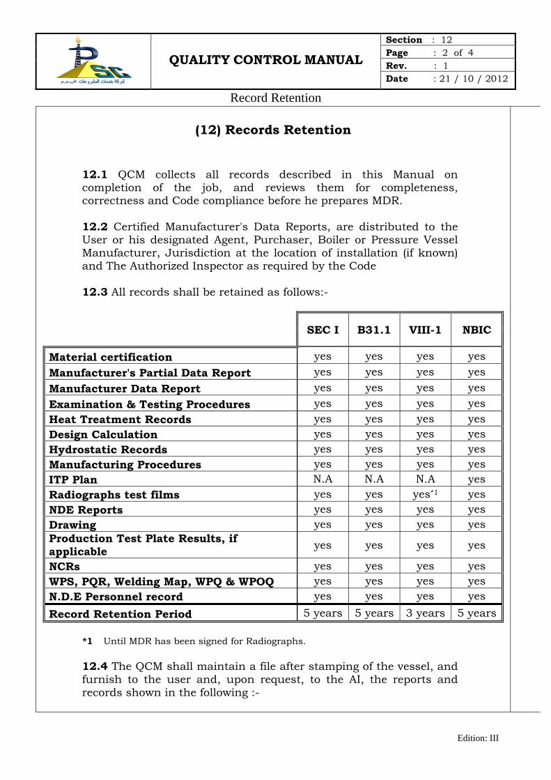
QUALITY CONTROL MANUAL Section : 12 Page : 2 of 4 Rev. : 1 Date : 21 / 10 / 2012
Record Retention
Edition: III
(12) Records Retention
12.1 QCM collects all records described in this Manual on completion of the job, and reviews them for completeness, correctness and Code compliance before he prepares MDR. 12.2 Certified Manufacturer's Data Reports, are distributed to the User or his designated Agent, Purchaser, Boiler or Pressure Vessel Manufacturer, Jurisdiction at the location of installation (if known) and The Authorized Inspector as required by the Code 12.3 All records shall be retained as follows:-
SEC I B31.1 VIII-1 NBIC
Material certification yes yes yes yes Manufacturer's Partial Data Report yes yes yes yes Manufacturer Data Report yes yes yes yes Examination & Testing Procedures yes yes yes yes Heat Treatment Records yes yes yes yes Design Calculation yes yes yes yes Hydrostatic Records yes yes yes yes Manufacturing Procedures yes yes yes yes ITP Plan N.A N.A N.A yes Radiographs test films yes yes yes*1 yes NDE Reports yes yes yes yes Drawing yes yes yes yes Production Test Plate Results, if applicable yes yes yes yes
NCRs yes yes yes yes WPS, PQR, Welding Map, WPQ & WPOQ yes yes yes yes N.D.E Personnel record yes yes yes yes Record Retention Period 5 years 5 years 3 years 5 years
*1 Until MDR has been signed for Radiographs. 12.4 The QCM shall maintain a file after stamping of the vessel, and furnish to the user and, upon request, to the AI, the reports and records shown in the following :-
QUALITY CONTROL MANUAL Section : 12 Page : 3 of 4 Rev. : 1 Date : 21 / 10 / 2012
Record Retention
Edition: III
a) Manufacturer's Data Report with Manufacturer's Partial Data
Report.
b) Manufacturer's Construction Records and Partial Data Reports shown in the following:-
1) Tabulated list of all material used for fabrication with
Materials Certifications and Material Test Reports (CMTRs)& (MTRs) as required and a record of any repairs along with the repair procedures.
2) Fabrication information including all heat treatment requirements, forming and rolling procedure when prepared, an Inspection and Test Plan identifying all inspection points required by the user, and signed inspection reports.
3) List of any subcontracted services, if applicable.
4) WPSs, PQRs, weld map and WPQs and WOPQs.
5) Record of all heat treatments including post weld heat
treatment.
6) Results of production test plates, if applicable.
7) NDE procedures, records of procedure demonstrations, and records of personnel certifications.
8) All reports stating the results of inspection, non-destructive
examinations and testing including RT, UT, MT, PT and VT examination and hardness tests, if applicable.
9) All non-conformance reports including resolution and a
detailed description of any repairs including repair procedures, a sketch, photo, or drawing indicating the location and size of the repaired area.
10) Charts or other records of required hydrostatic, pneumatic, or other tests. Test logs shall include the test date, testing fluid, duration of the test, temperature of the test fluid, and test pressure.
11) Dimensional drawings of the as-built condition.
QUALITY CONTROL MANUAL Section : 12 Page : 4 of 4 Rev. : 1 Date : 21 / 10 / 2012
Record Retention
Edition: III
12.5 National Board serial numbers, for each Code Item to be registered, are controlled and issued consecutively from 1 by QCM, who maintains a record of each number with date issued, type of Boiler, Vessel or part, name and location of Purchaser, and Manufacturer's serial number. National Board numbers are issued at the time of hydrostatic or pneumatic test completion. When not tested in the shop, the National Board serial number shall be issued at the time of MDR signing. These numbers shall be issued without skips or gaps of unused numbers or duplications or prefixes or suffixes. 12.6 QCM sends the originals of Manufacturer's Data Report with attached Manufacturer's Partial Data Reports, to the National Board for each Code stamped Boiler, Vessel or Part to be registered within sixty days of certification date by the AI.
QUALITY CONTROL MANUAL Section : 13 Page : 1 of 3 Rev. : 1 Date : 21 / 10 / 2012
Authorized Inspector
Edition: III
Authorized Inspector
QUALITY CONTROL MANUAL Section : 13 Page : 2 of 3 Rev. : 1 Date : 21 / 10 / 2012
Authorized Inspector
Edition: III
(13) Authorized Inspector
13.1 The Authorized Inspector is the Inspector required by the Code, employed by the ASME Accredited Authorized Inspection Agency (AIA) with whom PSC has an inspection contract or valid written agreement to perform the inspection services required by the Code, he holds a valid Certificate of Competency issued by a State of the United States of America or a Province of Canada and a valid National Board Commission with an "A" Endorsement.
13.2 The Authorized Inspection Agency of Record shall perform all required inspections at the shop location. Alternatively at the request of the purchaser another Authorized Inspection Agency may perform inspections in the shop on its project or Code job.
13.3 The Authorized Inspection Agency of Records shall perform all inspections at field site location. The AIA of Record would not perform the inspections at the field site when…
13.3.1 The purchaser requests another Authorized Inspection Agency to perform inspections on its project or Code jobs.
13.3.2 Whenever the AIA of Record cannot provide coverage for inspections at a specific field site.
13.4 When an AIA other than the AIA of Record performs inspections…
13.4.1 The AIA that will perform the activities shall perform it in accordance with the Quality Control Manual of PSC, in case of any difference than the Quality Control Manual; PSC shall notify the AIA of Record and take his acceptance for the difference.
13.4.2 A Contract or written agreement will be made between PSC and the AIA performing field/shop activities for that specific Code work.
13.4.3 PSC shall notify the AIA of Record and ASME Organization whenever the written agreement has been canceled, or changing to another inspection agency.
QUALITY CONTROL MANUAL Section : 13 Page : 3 of 3 Rev. : 1 Date : 21 / 10 / 2012
Authorized Inspector
Edition: III
13.5 The rules of the Code shall serve as the basis for The AI to… 1. Perform his required duties. 2. Authorize and witness the application of Code Symbol
Stamp. 3. Sign the MDR of Shop Inspection and / or Field Assembly.
13.6 QCM arranges for The Authorized Inspector and the AI Supervisor to have free access to the Shop and Field Site and Subcontractors facilities to assure that all Code required inspections by the AI are performed.
13.7 When requested by The Authorized Inspector, inspection
points will be inserted in ITP for those operations he may wish to witness or verify before work proceeds.
13.8 QCM is liaison with The Authorized Inspector, and is
responsible for keeping him informed of the progress of Code Work so that he may make his designated inspections.
13.9 The Authorized Inspector has access to and is provided with
all drawings, calculations, specifications, procedures, process sheets, repair records, test and examination results, inspection records and any other documents required to perform his duties.
13.10 All Nonconformance Reports for Code Nonconformities are
submitted to The Authorized Inspector with proposal for resolution of Nonconformities for his review and acceptance.
13.11 QCM will notify the Authorized Inspector in advance of Code
required pressure test so that he will be present to witness such. 13.12 The final records, together with the completed MDR certified
by QCM, are submitted to AI for his authorization to apply the Code Symbol Stamp and Signature, when he has satisfied himself that all Code Requirements have been met.
13.13 A current controlled copy of the Quality Control Manual is
made available for use by the AI at the Shop and Field Site. 13.14 All changes to Quality Control Manual to be submitted to the
AI for his review prior to implementation. 13.15 QCM will assist the Authorized Inspector Supervisor (AIS)
during his required audits and the Authorized Inspector whilst periodic monitoring the Quality Control System.

QUALITY CONTROL MANUAL Section : 14 Page : 1 of 5 Rev. : 1 Date : 21 / 10 / 2012
Field Assembly
Edition: III
Field Assembly
QUALITY CONTROL MANUAL Section : 14 Page : 2 of 5 Rev. : 1 Date : 21 / 10 / 2012
Field Assembly
Edition: III
(14) Field Assembly
14.1 Scope This Section describes the system for assuring that all requirements of the Code and Client's Specifications are met with respect to Site work required in connection with the construction of Boiler, Power Piping and Pressure Vessels. Site Work will only consist of completion or assembly of Vessels, Boiler or Piping Systems which, because of size or convenience cannot be completed at the Shop. 14.2 Organization. As indicated in the PSC Organization Chart Section "3" of this Quality Control Manual, Construction Manager is responsible for all activities concerning each site on the basis of the documents transmitted by TOH and by QCM. The Site Quality Control Engineer reports directly to Site Manager administratively and for all Site quality Control activities and to the QCH at the shop. Directly under the Authority of the Construction Manager there is the Site Manager who is responsible for the Field assembly activities on Site. 14.3 Preparation of Drawings, Design, Calculations, Fabrication Specifications and Procedures. The preparation and review of these documents shall be handled in accordance with Section 4 of this Quality Control Manual (Dealing with Design, Calculations, Drawings and Specifications). All documents for ASME Site Work orders shall be marked with the "SITE WORK ONLY" Stamp. 14.4 Revision of Documents. All revisions of documents shall be handled in the same manner as the original documents. 14.5 Distribution and Revision of Site Assembly Data. The distribution of Site Fabrication Data as well as the distribution of revisions to Site Fabrication Data shall be handled in accordance with Section "4" of this Quality Control Manual Dealing with Design, Calculations, Drawings and Specifications).. 4.6 Material Control 14.6.1 Ordering of Code Material. All materials to be used for Site Work shall be ordered in accordance with Section "5" of this Quality Control Manual (Dealing with the Material Control). Purchasing of material at Field Sites is not permitted.
QUALITY CONTROL MANUAL Section : 14 Page : 3 of 5 Rev. : 1 Date : 21 / 10 / 2012
Field Assembly
Edition: III
14.6.2 Material Receiving Inspection. All Materials are subjected to receiving inspection in accordance with Section "5" of this Quality Control Manual at Site. This shall be performed by the Site Quality Control Engineer and documented on the Material Receiving Inspection Form.
14.6.3 Control of Code Material. Only material procured, inspected and released by PSC shall be used on Code Site Work and the general procedure shall be in accordance with Section "5" of this Quality Control Manual dealing with Material Control. 14.6.4 Ordering of Welding Material. Welding Material shall be ordered in accordance with Section "5" of this Quality Control Manual (Dealing with the material control).
14.6.5 Receiving Inspection of Welding Material. All incoming welding materials shall be subject to receiving inspection by Site Quality Control Engineer in accordance with Section "5” of this Quality Control Manual dealing with Material Control. .
14.6.6 Storage of Welding Material. Welding Material shall be stored in accordance with Section "8" of this Quality Control Manual. The Site Quality Control Engineer shall be responsible for correct storage dealing with Welding Control.
14.7 Examination and Inspection Program. All Site Work shall be controlled through the use of the field ITP together with Line Inspection Summary List (LISL) Exhibit No.(14-01) in accordance with Section "6" of this Quality Control Manual dealing with Examination and Inspection Program. It is the responsibility of the Site Quality Control Engineer to review ITP/LISL with the Authorized Inspector prior to begin of assembly, erection or any other field work. After hydrotesting of completed Code items, which is offered to the site AI for witness, the ASME stamp obtained from QCM by the site QC Eng. Shall be applied to the Name Plate after authorization from the site AI, The ASME stamp shall be returned by the site QC Eng. To the QCM at shop for safe keeping. The MDR for Code item completed at the site location after final inspection and testing field assembly portion of the MDR is signed y the QC Eng. And presented to the site AI for his signature ,the complete MDR is send to the QCM at shop for distribution as required
QUALITY CONTROL MANUAL Section : 14 Page : 4 of 5 Rev. : 1 Date : 21 / 10 / 2012
Field Assembly
Edition: III
All originals of Site Work Inspection reports shall be submitted to Site QC engineer for his review and signature.
14.8 Nonconformities. All Non-conformities found during Site work shall be handled in accordance with Section "7" of this Quality Control Manual dealing with Correction of Non-conformities. Except that the Site Quality Control Engineer shall be responsible for preparing the Nonconformance Report including approval of disposition.
14.9 Welding Control. The Welding Control and the preparation and qualification of WPS & WPQ shall be handled in accordance with Section "8" of this Quality Control Manual dealing with Welding Control. Except that the Site Quality Control Engineer is responsible for Qualification of the Welding Procedures and Welders. Copies of Welding Procedure Specifications (WPSs), Procedure Qualification Records (PQRs) and Welder/Welding Operator Performance Qualification Records (WPQs) shall be available to the Authorized Inspector on Site for review.
14.10 Post Weld Heat Treatment. When it is necessary to perform PWHT at a Field Site it shall be by PSC or by Subcontractor.
PSC QCH is responsible for the development of PWHT Procedures and approval in accordance with Section “10".
Site QC Engineer shall be responsible for verifying calibration of subcontractor's PWHT equipment. Copies of time/temperature charts and other PWHT records will be reviewed and approved by Site QC Engineer and made available to the Authorized Inspector for review.
14.11 Non-Destructive Examination. The Control and Implementation of NDE Procedures on Site shall be handled in accordance with Section "9" of this Quality Control Manual dealing with Non Destructive Examination.
14.12 Control of Measuring and Test Equipment. All Calibration of PSC measuring and test equipment to be used at site shall be handled in accordance with Section "11" of this Quality Control Manual dealing with Calibration of Measurement &Test Equipment. Measuring and test equipment from Subcontractor shall be calibrated in accordance with their procedures which have been accepted by PSC QCM. It is the responsibility of Site Manager to ensure that only calibrated and identified equipment is used for Site Work.
QUALITY CONTROL MANUAL Section : 14 Page : 5 of 5 Rev. : 1 Date : 21 / 10 / 2012
Field Assembly
Edition: III
14.13 Records Retention. Quality Control Documents shall be prepared and maintained in accordance with Section "12" of this Quality Control Manual dealing with Record Retention. 14.14 Authorized Inspector (AI). The contractual relationship with an Authorized Inspection Agency, access for the Authorized Inspector at site and coordination with the Authorized Inspector shall be handled in accordance with Section "13" of this Quality Control Manual dealing with Authorized Inspector. The Site QC Engineer is the liaison officer with the AI at site. PSC shall provide suitable working facilities for AI and AIS at site.
QUALITY CONTROL MANUAL Section : 15 Page : 1 of 10 Rev. : 1 Date : 21 / 10 / 2012
Repairs and Alterations
Edition: III
Repairs and Alterations
QUALITY CONTROL MANUAL Section : 15 Page : 2 of 10 Rev. : 1 Date : 21 / 10 / 2012
Repairs and Alterations
Edition: III
(15) Repairs and Alterations
15.1. General :
15.1.1. Repairs and Alteration can be carried out on ASME Code stamped/Certification Marked boiler and pressure vessels and also on other vessels not designed to ASME Codes.
15.1.2. Shop or field repairs and alterations to boilers, power piping or pressure vessels when required by the Owner, User, Jurisdiction or AIA responsible for in-service inspection of the unit, are made in accordance with the applicable requirements of the National Board Inspection Code (NBIC) and this Quality Control Manual.
15.1.3. “REPAIR” is defined as the work necessary to restore pressure
retaining item to a safe and satisfactory operating condition.
15.1.4. “ALTERATION” is defined as change in the item described on the original Manufacturer’s Data Report which affects the pressure containing capability of the pressure retaining item. Non-physical changes such as an increase in the MAWP OR MAEWP or design temperature or a reduction in the minimum design metal temperature of a pressure retaining item shall also be considered an Alteration.
15.1.5. “RE-RATING” is an Alteration, rerating shall be applicable only when
the current inspection records indicate the vessel is in satisfactory condition, its design with the existing condition is verified and the vessel is pressure tested to the rerated condition (Part 3 Ref 3.4.1 of NBIC)
15.2. Statement Of Authority And Responsibility
15.2.1. QCM is responsible for compliance with this Manual for shop or field
repairs and alterations to pressure vessels. (See Section 2 of this Manual)dealing with statement of Authorty and Resposiblity.
15.3. Manual Control
15.3.1 The preparation, revision and issue of this Quality Control Manual
shall be the responsibility of QAH. The system has been detailed in Section-1 of this Manual dealing with Manual control.
QUALITY CONTROL MANUAL Section : 15 Page : 3 of 10 Rev. : 1 Date : 21 / 10 / 2012
Repairs and Alterations
Edition: III
15.4. Organization
15.4.1 The Organization Chart for carrying out repair and alteration at shop
and field sites controlled from shop shall be as shown in Section-3 of this Manual and the Quality Control responsibilities are as detailed in Section-3 of this Manual dealing with Organization.
15.5. Construction Standards
15.5.1. When original equipment is constructed to the ASME Code, repairs and alterations shall conform insofar as possible to the section and Edition of the ASME Code most appropriate to the work performed.
15.5.2. When the original equipment is not constructed to the ASME Code, repairs and alterations shall conform insofar as possible to the edition of the construction standard or specification most appropriate to the work. Where use of original construction code is not possible or practicable, other codes, standards, specifications including ASME Code with latest Edition and Addenda may be used provided prior concurrence of the AI has been obtained. When applicable prior concurrence of Jurisdiction and Owner shall also be obtained for use of standards other that original construction standard.
15.6. Drawings, Design And Specifications
15.6.1. On receiving the order for carrying out Repairs or Alteration, it shall
be the responsibility of assigned Design Engineer ( See Section 4 of this Manual) dealing with Design,Calculation,Drawing and Specification to identify and confirm whether the required work is categorized as Repair or Alteration or Rerating in accordance with the requirements of NBIC NB23.
15.6.2. He shall also be responsible to ensure that sufficient information
has been provided by the owner or user along with the order so that repair or alteration work can progress. He shall ensure availability of the MDR, drawings, data sheets and similar other documents required to undertake the repair or alteration work. If data reports are not available and the vessel is registered with National Board (as verified from the vessel name plate/stamping or Certification Marking), he shall arrange a copy from the National Board by providing the necessary information like name of the manufacturer, Code item serial number, year make and NB number.
QUALITY CONTROL MANUAL Section : 15 Page : 4 of 10 Rev. : 1 Date : 21 / 10 / 2012
Repairs and Alterations
Edition: III
15.6.3. The system of preparation of design calculations shall be as explained in Section-4 of this Manual dealing with Design,Calculation,Drawing and Specification. The design calculations for repair or alteration shall be based on the original construction standard or as otherwise specified in Para.15.5 above. Reference for design shall be based on MDR and other details like drawings, data sheet etc., given by the owner. Design calculations shall clearly identify the Code/Standard used including their year date and addenda.
15.6.4. Drawings for alterations (and when required for repairs) shall be
approved by TOH. In addition to the applicable details given in Section-4 , the drawings shall also indicate the original construction Code, construction Code used for repairs/alterations, applicable National Board Inspection Code addenda and name plate stamping details. Distribution and revision to the drawings shall be controlled in the manner described in Section-4 dealing with Design,Calculation,Drawing and Specification.
15.6.5. Design Engineer is also responsible for verifying the identification of
the existing materials from the original MDR, original drawings and other such documents. Material specification for the existing material and material to be installed shall be clearly indicated on the drawings.
15.6.6. When any material or part is to be replaced during repairs or
alteration, Technical specifications for material shall be prepared by the Design Engineer and approved by TOH as described in Section-4 of this Manual dealing with Design,Calculation,Drawing and Specification.
15.6.7. All design documents shall be submitted to the AI for his review
before proceeding further with repairs or alterations.
15.7. Materials
15.7.1. The use of stock material, procurement, receipt inspection, storage, issue and identification of material shall be as described in Section-5 of this Manual dealing with Material Control.
15.7.2. All materials used in making repair or alteration shall conform to the requirements of original construction standards or as specified in Para.15.5 above.
15.7.3. The relevant material test reports or certificate of compliance shall
be obtained and submitted to the AI for his review and acceptance.
15.7.4. Carbon or alloy steels having carbon content more than 0.35% shall
QUALITY CONTROL MANUAL Section : 15 Page : 5 of 10 Rev. : 1 Date : 21 / 10 / 2012
Repairs and Alterations
Edition: III
not be used for items requiring welding.
15.7.5. Replacement parts shall meet the requirements of Sec. 3 of Part 3 of NBIC NB23.
15.7.6. When ASME is the original Code of construction, replacement parts
which require welding shall be fabricated, inspected and documented as per ASME Code as parts. When original Code of construction is not ASME, replacement parts which require welding shall be fabricated, inspected and documented as per the original construction Code and if this is not practicable, such items can be constructed and stamped R by the R symbol stamp holder and documented on Form R-3 of NBIC NB23.
15.8. Welding, NDE And Heat Treatment
15.8.1. Welding controls including qualification of welding procedures and welders, control of welding consumables, welder’s identity & continuity control and shop/field welding controls for repairs and alterations shall be in accordance with Section-8 of this Manual dealing with Welding, NDE and Heat Treatment.
15.8.2. The welding procedures and welder’s qualification shall conform to original construction standard. If this is not possible or practicable, WPS and welders qualified in accordance with ASME Code Sec. IX can be used. Records of approved WPS and welder’s qualification tests shall be made available to the AI for his review and acceptance before carrying out welding work.
15.8.3. Standard WPS shown in Part 3, Table 2.3 of the NBIC NB23 can be
used for repairs or for performance qualification. Such WPS shall be documented and certified by QC Head for use. When required, owners or jurisdiction’s acceptance will be obtained for use of standard WPS.
15.8.4. NDE requirements including technique, extent of coverage,
procedures, personnel qualification and acceptance criteria shall be in accordance with original construction standard. Weld repairs and alterations shall be subjected to same NDE requirements as the original welds. When this is not possible or practicable, alternative NDE methods acceptable to the AI and owner or jurisdiction as applicable may be used.
15.8.5. NDE personnel shall be qualified in accordance with the
requirements of original construction standard. When this is not possible or practicable, personnel qualified in accordance with latest
QUALITY CONTROL MANUAL Section : 15 Page : 6 of 10 Rev. : 1 Date : 21 / 10 / 2012
Repairs and Alterations
Edition: III
NBIC adopted edition of SNT-TC-1A may be used.
15.8.6. Other NDE controls shall be as per Section-9 of this Manual dealing with Welding, NDE and Heat Treatment
15.8.7. Preheat temperature requirements shall be as specified in the applicable WPS.
15.8.8. PWHT shall be performed as required by the original construction
standard or as per original manufacturer’s data report. PWHT shall be in accordance with procedure and instructions prepared and approved as detailed in Section-10 of this Manual dealing with Welding, NDE and Heat Treatment. Local PWHT that is not specified by the original construction code may be performed as per Sec. 2, Part 3 of NBIC NB23 with prior acceptance of the AI and when required by the owner and Jurisdiction.
15.8.9. Under certain conditions, when PWHT in accordance with original
construction standard is inadvisable or impractical, alternative methods of PWHT or special welding methods as described in Part RD of NBIC NB23 and acceptable to the AI may be used.
15.9. Examination And Tests
15.9.1. All examination and tests required during and after repairs or alterations shall be identified on the Repair procedure and ITP.
15.9.2. Requirements for the pressure tests including test medium, test pressure, holding time, and temperature limits etc. shall be specified in the repair procedure.
15.9.3. All pressure tests shall be witnessed by the QC Head and shall be
offered to the AI.
15.9.4. The extent of Pressure Testing shall be as acceptable to the AI and the owner/user. When it is not possible or practicable to pressure test the whole equipment on which repairs or alterations have been carried out, only connecting welds (defined as welds attaching replacement parts and pressure retaining item) may be tested.
15.9.5. The metal temperature during Pressure Test shall not be less than
60°F (16°C) or more than 120°F (50°C). Care shall be taken to ensure that the pressure relief devices on the equipment are either removed or gaged before test. Test pressure shall be held for minimum of 10
QUALITY CONTROL MANUAL Section : 15 Page : 7 of 10 Rev. : 1 Date : 21 / 10 / 2012
Repairs and Alterations
Edition: III
minutes prior to the examination. The AI shall be afforded the right to carry out the close examination after reducing the pressure to MAWP.
15.9.6. When Liquid Pressure Test is not practicable the QC Head shall obtain the acceptance of the AI and the owner/user for carrying out alternative test as described in NBIC NB Part 3 Sec.4. This acceptance shall be obtained and recorded before performing any alternative examination or testing.
15.10. Non-Conformities
15.10.1. Any non-conformity noticed during execution of repairs and alterations shall be dealt in accordance with Section-7 of this Manual dealing with Correction Of Nonconfomities.
15.11. Calibration
15.11.1. All equipment and gauges used for inspection and examination during repair and alterations shall be maintained and calibrated in accordance with Section-11 of this Manual dealing with Calibration Of Measurementand Test Equipment.
15.12. Procedure :
15.12.1. All repairs and alterations to Code pressure vessels are subject to acceptance of the Authorized Inspector, who may require that evidence of acceptance of the method and extent of repairs or alteration by the jurisdiction or insurance carrier responsible for in-service inspection be provided before starting work.
15.12.2. The Quality Control Manager, prior to the start of work, provides the Authorized Inspector with drawings, calculations, procedures, Repair Inspection and test plan (ITP), copy of the original Manufacturer’s Data Report (for ASME Code stamped items) for the item and any other documents necessary for the Authorized Inspector to review and accept the method of repair or alteration and to designate his required inspection points.
15.12.3. For alterations consisting only of re-rating, calculations can be
obtained from the original manufacturer.
15.12.4. The Quality Control Manager, if requested by the Authorized Inspector, arranges for his access to make such inspections of the vessel he deems necessary in order to accept the method of repair or alteration.
QUALITY CONTROL MANUAL Section : 15 Page : 8 of 10 Rev. : 1 Date : 21 / 10 / 2012
Repairs and Alterations
Edition: III
15.12.5. The Quality Control Manager keeps the Authorized Inspector
informed of the progress and completion of the work so he may make his designated inspections, and accept the repair or alteration after his final inspection of the completed work.
15.12.6. All examinations and tests required by the Code for the original construction of the pressure vessel are required for repair or alteration, except that if impossible or impracticable, alternative method acceptable to the Authorized Inspector may be used.
15.12.7. For alterations, if the original Manufacturer's Data Report cannot be
obtained, agreements on the method of establishing design basis for alteration shall be obtained from the Inspector and the jurisdiction.
15.13. Records :
15.13.1. The repair or alteration including a description of the relocation of
Code Stamping or Nameplate is documented on the current National Board Form R1-Report of repair or Form R2-Report for alteration.
15.13.2. When the work is complete, the Form R1 or R2 is certified by the
Quality Control Manager.
15.13.3. The final records together with the completed Form R1 or R2 as applicable; and the original Manufacturer’s Data Report are presented to the Authorized Inspector for his review. When he has satisfied himself that all NBIC and Manual requirements have been met, he will authorize the application of the “R” symbol to the appropriate NBIC stamping and sign the Form R1 or R2.
15.13.3.1. When altration /rerating is carried out Design Certification Section of form R2 shall be designed by TOH (Technical Office Head) prior to presenting the same to the AI for his review and acceptance with his signature.
15.13.4. All records referenced in this Section are available for review by the
Authorized Inspector. Forms R1 or R2 is distributed as described in 15.6.
15.13.5. LOG OF R- FORMS (Exhibit No. 15-01) shall be used to record
details of all R-Forms issued .The "R" Form Number shall be assigned by the Quality Control Manager sequentially starting from 'R1' (then after R2, R3, etc.). 1 without any skips and gaps of unused number.
15.14. Stamping :
QUALITY CONTROL MANUAL Section : 15 Page : 9 of 10 Rev. : 1 Date : 21 / 10 / 2012
Repairs and Alterations
Edition: III
15.14.1. If, during repair or alteration of a pressure vessel, it is necessary to remove the original Manufacturer’s Code stamping/Certification Marking or Nameplate, the Authorized Inspector will, subject to the approval of the jurisdiction:
(a) Witness the marking of a facsimile or rubbing of the old and new stamping;
(b) Witness obliteration or removal of the old stamping, and transfer of the stamping to the new part or location on the item, less the original Code symbol/Certification Marking. The Code symbol/Certification marking is not re-stamped.
15.14.2. When stamping is on a Nameplate, the Authorized Inspector will
witness the transfer of the Nameplate to its new location.
15.14.3. The Quality Control Manager retains custody and control of the “R”-Stamp. Stamping may either be on the Code item or on a name plate. Marking shall be as indicated in Marking/Name Plate for ‘R’ stamp (Exhibit No. 15-02.). This symbol is the property of the national Board and shall be retained on demond to National Board.
15.15. Distribution Of Forms R1 Or R2 :
15.15.1. Legible copies of completed Form R1 (for Repairs) together with
attachments shall be distributed to the Owner or user, the Authorized Inspector, the jurisdiction (if required) and the AIA responsible for in-service inspection.
15.15.2. Form R1 may be registered with the National Board, regardless of the pressure-retaining item is originaly registered or not registered with the National Board.
15.15.3. Legible copies of completed R2 (for Alteration) together with
attachments, shall be distributed to the Inspector, the AIA responsible for in-service inspection, Owner or user, the 'R' Certificate holder responsible for design and the jurisdiction (if required).
15.15.4. If the pressure-retaining was registered originaly with the National
Board, one original Form R2 together with attachments shall be registered with the National Board.
15.15.5. If the pressure-retaining item is not registered with the National
Board, one original Form R2 together with attachments may be registered with the National Board.
QUALITY CONTROL MANUAL Section : 15 Page : 10 of 10 Rev. : 1 Date : 21 / 10 / 2012
Repairs and Alterations
Edition: III
15.16. Replacement Parts
15.16.1. When the original Code of construction is ASME, any replacement
part of boiler or pressure vessel required shall be constructed, certified and Marking as per the rules of the ASME construction Code.When the original Code of construction is other than ASME, any replacement part of boiler or pressure vessel required shall be constructed to the original Code of construction and shall be stamped “R”. Replacement parts shall be reported on Form R-3 which shall be certified by the Quality Control Manager and presented to the AI for review and signature.
15.17. Routine Repairs
15.17.1. When routine repairs, as defined in NBIC, Part 3, 3.3.2 are required, the Quality Control Manager shall ensure that the routine repairs are acceptable to the jurisdiction.
15.17.2. The Jurisdiction ( if required) or the Inspector may waive the involvment of the AI in the routine repairs. Application of the ‘R’ symbol Stamp on the item repaired may also be waived as determined by jurisdiction or the AI.Routine repairs shall be documented on form R-1 with this statement in the Remarks section : “Routine repair”
15.17.3. Repair procedure / ITP for routine repairs shall be prepared and
submitted to the AI for his acceptance and signature.
15.17.4. Form R-1 shall be prepared and certified by the Quality Control Manager, and shall include a statement “Routine Repairs” in the Remarks column in the R-Form. R-1 form shall be submitted to AI for his signature


![SOW/PWS DATE [Department], [Agency] - gsa.gov · The QCP shall include a quality control matrix (QCM), such as the sample QCM shown in Table The QCM shall reflect the quality 2. approach](https://img.pdfslide.us/doc/110x75/5b9a646e09d3f24f678ba3b8/sowpws-date-department-agency-gsagov-the-qcp-shall-include-a-quality.jpg)