Embed Size (px)
Citation preview
Quality Improvement in Finished Cold Rolled Sheet by reducing the defect
Ranjan Prakash*, Baidya Nath Roy** *Student, M.Tech. Metallurgical Engineering Department, B.I.T.Sindri, Jharkhand, India. ** Assistant Professor, Metallurgical Engineering Department, B.I.T.Sindri, Jharkhand, India.
Abstract— As manufacturing speed increases in the steel industry, fast and exact product inspection becomes more important. This project deals with defect detection and classification algorithm for cold rolled coil along with minimization of those defects by adopting some suitable corrective action during the process of manufacturing. We can enhance an acquired image by use of a special subtractive method and find the position of defect using local entropy and morphology. Practically the all defects in cold rolling inspected before dispatching the material to the customer at skin pass mill. R&C Inspection wings generally focused over four “S” i.e. Shape, Size, Surface and Safety during their inspection. Cold rolling improves the surface finish and holds tighter tolerances. This will certainly affect the quality of product in terms of high production, since they are critical. This will also increases the product evolution in the opened market. Better co- ordination among quality and production will help in achieving greater efficiency to produce high quality cold rolled sheet. Manufacturer should have maintained zero defects so that their products should not be rejected in the global market. Besides, we should also keep in mind that manufacturing should not have any negative impact on our environment. No one can rule out the global opportunities which are knocking the doors of Indian economy. But, to capitalize this global opportunity Indian entrepreneur must have to achieve manufacturing excellence and have to carefully work upon competitive enhancement for their respective business. Any defect in the material may result rejection of final product that leads to major loss in terms of money and sometimes major accidents also.
Index Terms— Entropy, Skin Pass Mill, Cold Rolled, Morphology, R&C, Annealed, Recrystallization, Hot rolling.]
—————————— ——————————
1 INTRODUCTION
Due to economic globalization, industry is facing severe
competition from foreign competitors. To get success in this environment, the industry must significantly improve produc-tivity and quality and reduce defect less product and waste during production. In addition to economic consideration, the environmental concern and energy consumption requirement also strongly derive steel industry toward that direction there-fore; there is an urgent need from steel industry for effective process quality control. Since the rolling operation is often the last process step of raw materials of several products, hence the scrap from defects at rolling stage is very costly and the quality control of rolling process has a vital role. In present work we establish voice of customer, which really state much about the customer satisfaction, type of customer also. The work has been carried out at Bokaro Steel Plant, SAIL to min-imize the defects in cold rolling products. In the present work internal customer ship is divided among the whole process flow. Slab is the customer of reheating furnace, Reheated Slab is the customer of the Hot rolling mill, Hot rolled product is the customer of Cold rolling mill and cold rolled product is the customer of the inspection department. If these customers are satisfied, external customers will automatically be satis-fied. [1] The issue of Quality Control is an important aspect of today’s highly competitive Industry. One important way to improve the quality of the end product is to inspect the output of each manufacturing process. However, Manual inspection of end
products slows down the entire process as it becomes costly, time consuming and also may impact the effectiveness of hu-man labour due to the hazardous atmosphere of industry.[2] Manufacturer should have maintained zero defects so that their products should not be rejected in the global market. Besides, we should also keep in mind that manufacturing should not have any negative impact on our environment. No one can rule out the global opportunities which are knocking the doors of Indian economy. But, to capitalize this global op-portunity Indian entrepreneur must have to achieve manufac-turing excellence and have to carefully work upon competitive enhancement for their respective business [3]. Any defect in the material may result rejection of final product that leads to major loss in terms of money and sometimes major accidents also. [1] Major functions of this case study is to improved product quality with respect to Chemical composition of Steel, me-chanical properties of product with good geometry of rolled product having best surface quality of product. A measure of quality parameter includes the chemical composition, mechan-ical properties, dimensional Accuracy and free from Surface Defects.Defects are inherent to any manufacturing industry. A lot of resources and money is spent on minimizing this. Quan-tification of Defects helps reject defected pieces and manage mass production with ease. Cold Rolling Mill or CRM is the customer of Automobile industries. The cold rolled coils pro-duced are used in the everyday utility vehicles in the form of 2-Wheeler, 3-Wheeler and Multi Wheelers.
International Journal of Scientific & Engineering Research, Volume 7, Issue 3, March-2016 ISSN 2229-5518 595
IJSER © 2016 http://www.ijser.org
IJSER
TYPE OF DEFECT ORIGIN OF DEFECT
Annealing colour
PG gas composition, 680-720°C,cooled up to 100°C,1550-1650 ccal
Bad Shape Fluctuation of load ,1234 Black Patch Emulsion carry over, Grease or oil after TM. Ridge build up Improper elongation 5%
Baby coil Defect observed, 5T Tension between coiler. Body sticker 800-900°C achieved in annealing cycle Bulging Improper elongation 5%, Crown Roll Mark TM Foreign particle present between roll. Damaged Wrong handling of oil. dent Mark Work roll impression Edge Sticker Stress, 800-900°C achieved in annealing cycle, Edge Tearing Wrong handling, stickers Edge Wavy Crown, IP AS per operation Very old storage (2001-2010) Weld Pass Supervision negligence.
Gauge variation Max load 3000T, max tension between strand 120T, coiler and uncoiler tension 3T.
Heat Buckle High temp after annealing Improper coiling Poor quality of oil used, Spread roll problem
Improper coiling Uncoiler assembly , rough handling by crane, less tension in TM>3T
Iron Particle Oxidation after annealing, delay to arrive at SPM.
Off In Width Fluctuation of load ,1234 60,60,35,35T
Roll Mark SPM Improper RG, Foreign particle present between roll.
Roll Shade Foreign particle present between roll, failure of shot blasting.
Rusty Emulsion Proportion, corrosion Serrated Edge Bad trimming
Sliver Un shrouded casting, purging nozzle choked in ladle.
Telescopic Very low tension at uncoiler of TM, USP/Unrolled Operational fault Under Pickled Less concentration @ <12 for H2SO4 & <2 for HCL.
Table: 1 Classification of defect and their origin.
1.1 STICKER: ‘Sticker’ is an overall term for the plastic de-formations or flow and kink marks already apparent on steel strip on the temper mill during the uncoiling of the windings of the coil before it reaches the rolling gap. Stickers are pro-duced by the pressure welding of bare metal surfaces. It has not yet been decisively established whether this welding is caused by diffusion welding processes between two surfaces, sintering processes or other adhesion mechanisms. However, a number of different types of stickers have been observed. In some cases, the processes which create these defects have been identified. A. Ridge stickers: Ridge stickers are sharply limited defects over the width of the strip. These stickers are mainly caused by strip profile anomalies (such as ridges), which can cause high radial pressures within the windings. B. Spot stickers: Spot stickers are limited to localized spots on the strip. The main cause of these stickers is the local applica-tion of high pressures (by coil tongs, for example) and the un-
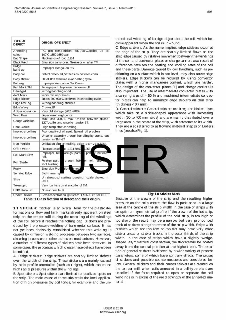
intentional winding of foreign objects into the coil, which be-come apparent when the coil is unwound. C. Edge stickers: As the name implies, edge stickers occur at the edge of the strip. They are sharply limited flaws on the strip edge caused by relative movement between the windings of the coil and convector plates or charge carriers as a result of differences between the heating and cooling rates of the coil and these parts. Damage caused by coil handling, such as po-sitioning on a surface which is not level, may also cause edge stickers. Edge stickers can be reduced by using convector plates with a higher manganese content, which are harder. The design of the convector plates [1] and charge carriers is also important. The use of intermediate convector plates with a carrying area of > 50 % and machined intermediate convec-tor plates can help to minimize edge stickers on thin strip (thickness < 0.7 mm). D. General stickers: General stickers are irregular kinked lines which take on a sickle-shaped appearance with increasing width (50 to 400 mm wide) and are mainly distributed over a large area in the centre of the strip, with reference to its width. They are also referred to as flowing material shapes or Luders lines (see also Fig. 1).
Fig: 1.0 Sticker Mark
Because of the crown of the strip and the resulting higher pressure on the strip centre, the flaw is positioned in a large area at the centre of the strip width in the case of strips with an optimum symmetrical profile. If the crown of the hot strip, which determines the profile of the cold strip, is too high or too sharp, the result may be a narrow but very pronounced track of stickers along the centre of the strip width. Strips with profiles which are too low or too flat may have very wide sticker areas or sticker tracks in the outer thirds of the strip width. In the case of strips which have a slightly wedge-shaped, asymmetrical cross section, the stickers will be located away from the central position at the highest part. The crea-tion of general stickers is affected by a wide variety of process parameters, some of which have contrary effects. The causes of stickers and possible countermeasures are considered be-low. General stickers and their causes Stickers are created on the temper mill when coils annealed in a bell-type plant are uncoiled if the force required to open or separate the coil windings is in excess of the yield strength of the annealed ma-terial.
International Journal of Scientific & Engineering Research, Volume 7, Issue 3, March-2016 ISSN 2229-5518 596
IJSER © 2016 http://www.ijser.org
IJSER
Before Annealing During Annealing After Annealing Steel Grade Hot Strip Profile Coiling tension Strip roughness Strip cleanliness Strip dimension Coil dimension
Cooling rate Heating up gradient Coil position
Uncoiling speed Uncoiling tension Uncoiling geometry
Table: 2 important factors affecting sensitivity to sticker formation
1.2 CHATTER MARK Periodic surface markings in the products manufactured through the rolling mills. These markings were preventing the product supplying high surface quality material from this par-ticular mill it is known as Chatter Marks. This defect appeared as alternative light and dark transversal stripes on both sur-faces of the strip seen under carefully controlled lighting con-ditions. Spacing of these stripes was regular and measured to be between 20 and 25 mm. No significant change of thickness was measured on the strip and the stripes were more preva-lent on fully annealed material. From the spacing of the defect and knowledge of the mill speed at the time, the frequency of the defect can be easily cal-culated. Strip marking results from forced vibrations acting on the work rolls and these may be amplified by natural reso-nances of the rolling mill. These natural resonances are typi-cally between 500 and 1000 Hz and are often referred to as the 5th octave resonances of the mill. In this case, the forced vibra-tion had a lower frequency and was of sufficient amplitude to mark the strip without excitation of any 5th octave resonance of the rolling mill. A survey of mill elements known to contribute to chatter was made, identifying defects in the work roll bearings inner races that were likely to create similar markings to the ones experi-enced in the mill, as shown in Figure 2. These defects were present in all the mill work rolls and were likely created dur-ing the chocking and de-chocking operations.[16].
Fig: 2 Defects in work roll bearing inner races
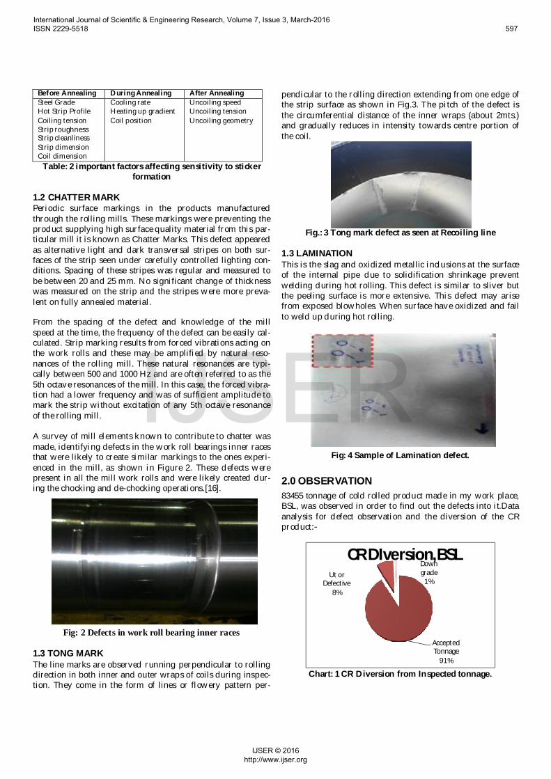
1.3 TONG MARK The line marks are observed running perpendicular to rolling direction in both inner and outer wraps of coils during inspec-tion. They come in the form of lines or flowery pattern per-
pendicular to the rolling direction extending from one edge of the strip surface as shown in Fig.3. The pitch of the defect is the circumferential distance of the inner wraps (about 2mts.) and gradually reduces in intensity towards centre portion of the coil.
Fig.: 3 Tong mark defect as seen at Recoiling line
1.3 LAMINATION This is the slag and oxidized metallic inclusions at the surface of the internal pipe due to solidification shrinkage prevent welding during hot rolling. This defect is similar to sliver but the peeling surface is more extensive. This defect may arise from exposed blowholes. When surface have oxidized and fail to weld up during hot rolling.
Fig: 4 Sample of Lamination defect.
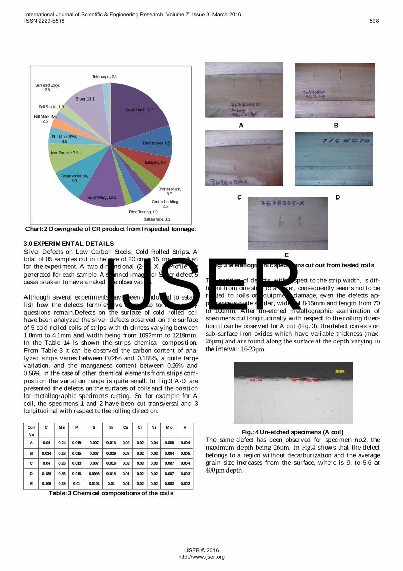
2.0 OBSERVATION 83455 tonnage of cold rolled product made in my work place, BSL, was observed in order to find out the defects into it.Data analysis for defect observation and the diversion of the CR product:-
Chart: 1 CR Diversion from Inspected tonnage.
Accepted Tonnage
91%
Ut or Defective
8%
Down grade
1%
CR DIversion,BSL
International Journal of Scientific & Engineering Research, Volume 7, Issue 3, March-2016 ISSN 2229-5518 597
IJSER © 2016 http://www.ijser.org
IJSER
Black Patch, 19.7
Body sticker, 8.5
Buldging, 6.4
Chatter Mark, 3.7
Center buckling, 2.5
dull surface, 3.3
Edge Tearing, 1.9
Edge Wavy, 12.6
Gauge variation, 8.9
Iron Particle, 7.8
Roll Mark SPM, 4.5
Roll Mark TM, 2.5
Roll Shade , 1.9
Serrated Edge, 2.5
Sliver, 11.1
Telescopic, 2.1
Chart: 2 Downgrade of CR product from Inspected tonnage.
3.0 EXPERIMENTAL DETAILS Sliver Defects on Low Carbon Steels, Cold Rolled Strips. A total of 05 samples cut in the size of 20 cm x 15 cm are taken for the experiment. A two dimensional (2-D), X, Y Profile are generated for each sample. A scanned image for Sliver defect 5 cases is taken to have a naked eye observation. Although several experiments have been conducted to estab-lish how the defects form/evolve from slab to strip, many questions remain.Defects on the surface of cold rolled coil have been analyzed the sliver defects observed on the surface of 5 cold rolled coils of strips with thickness varying between 1.8mm to 4.1mm and width being from 1092mm to 1219mm. In the Table 14 is shown the strips chemical composition. From Table 3 it can be observed the carbon content of ana-lyzed strips varies between 0.04% and 0.188%, a quite large variation, and the manganese content between 0.26% and 0.56%. In the case of other chemical elements from strips com-position the variation range is quite small. In Fig.3 A-D are presented the defects on the surfaces of coils and the position for metallographic specimens cutting. So, for example for A coil, the specimens 1 and 2 have been cut transversal and 3 longitudinal with respect to the rolling direction.
Coil
No
C Mn P S Si Cu Cr Ni Mo V
A 0.04 0.24 0.019 0.007 0.016 0.02 0.02 0.04 0.006 0.004
B 0.034 0.28 0.015 0.007 0.029 0.03 0.02 0.03 0.004 0.005
C 0.04 0.26 0.013 0.007 0.016 0.03 0.03 0.03 0.007 0.004
D 0.188 0.56 0.018 0.0096 0.015 0.01 0.02 0.02 0.007 0.003
E 0.106 0.35 0.01 0.0101 0.01 0.01 0.02 0.02 0.002 0.002
Table: 3 Chemical compositions of the coils
A B
C D
E Fig: 3 Metallographic specimens cut out from tested coils
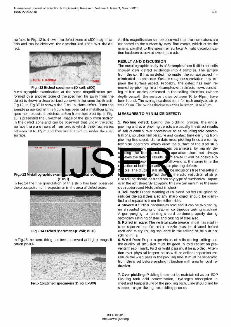
The position of defects, with respect to the strip width, is dif-ferent from one strip to another, consequently seems not to be related to rolls or equipment damage, even the defects ap-pearance is quite similar, width of 8-15mm and length from 70 to 100mm. After un-etched metallographic examination of specimens cut longitudinally with respect to the rolling direc-tion it can be observed for A coil (Fig. 3), the defect consists on sub-surface iron oxides which have variable thickness (max. 26μm) and are found along the surface at the depth varying in the interval: 16-23μm.
Fig.: 4 Un-etched specimens (A coil) The same defect has been observed for specimen no.2, the maximum depth being 26μm. In Fig.4 shows that the defect belongs to a region without decarburization and the average grain size increases from the surface, where is 9, to 5-6 at 400μm depth.
International Journal of Scientific & Engineering Research, Volume 7, Issue 3, March-2016 ISSN 2229-5518 598
IJSER © 2016 http://www.ijser.org
IJSER
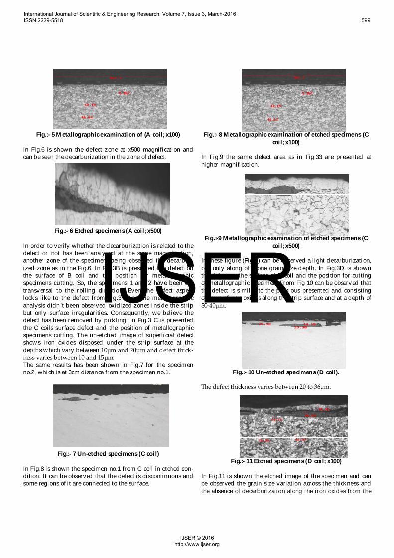
Fig.:- 5 Metallographic examination of (A coil; x100)
In Fig.6 is shown the defect zone at x500 magnification and can be seen the decarburization in the zone of defect.
Fig.:- 6 Etched specimens (A coil; x500)
In order to verify whether the decarburization is related to the defect or not has been analyzed at the same magnification, another zone of the specimen, being observed the decarbur-ized zone as in the Fig.6. In Fig.3B is presented the defect on the surface of B coil and the position for metallographic specimens cutting. So, the specimens 1 and 2 have been cut transversal to the rolling direction. Even the defect aspect looks like to the defect from Fig.3 A on the metallographic analysis didn`t been observed oxidized zones inside the strip but only surface irregularities. Consequently, we believe the defect has been removed by pickling. In Fig.3 C is presented the C coils surface defect and the position of metallographic specimens cutting. The un-etched image of superficial defect shows iron oxides disposed under the strip surface at the depths which vary between 10μm and 20μm and defect thick-ness varies between 10 and 15μm. The same results has been shown in Fig.7 for the specimen no.2, which is at 3cm distance from the specimen no.1.
Fig.:- 7 Un-etched specimens (C coil) In Fig.8 is shown the specimen no.1 from C coil in etched con-dition. It can be observed that the defect is discontinuous and some regions of it are connected to the surface.
Fig.:- 8 Metallographic examination of etched specimens (C
coil; x100) In Fig.9 the same defect area as in Fig.33 are presented at higher magnification.
Fig.:-9 Metallographic examination of etched specimens (C coil; x500)
In these figure (Fig.9) can be observed a light decarburization, but only along of a one grain size depth. In Fig.3D is shown the defect on the surface of D coil and the position for cutting of metallographic specimen. From Fig 10 can be observed that the defect is similar to the previous presented and consisting of rows of iron oxides along the strip surface and at a depth of 30-40μm.
Fig.:- 10 Un-etched specimens (D coil).
The defect thickness varies between 20 to 36μm.
Fig.:- 11 Etched specimens (D coil; x100) In Fig.11 is shown the etched image of the specimen and can be observed the grain size variation across the thickness and the absence of decarburization along the iron oxides from the
International Journal of Scientific & Engineering Research, Volume 7, Issue 3, March-2016 ISSN 2229-5518 599
IJSER © 2016 http://www.ijser.org
IJSER
surface. In Fig. 12 is shown the defect zone at x500 magnifica-tion and can be observed the decarburized zone over the de-fect.
Fig.:-12 Etched specimens (D coil; x500) Metallographic examination at the same magnification per-formed over another zone of the specimen far away from the defect is shown a decarburized zone with the same depth as in Fig.12. In Fig.3E is shown the E coil surface defect. From the sample presented in this figure has been cut a metallographic specimen, cross to the defect, at 5cm from the defect tip. In Fig. 13 is presented the un-etched image of the strip cross section in the defect zone and can be observed that under the strip surface there are rows of iron oxides which thickness varies between 10 to 17μm and they are at 16-27μm under the strip surface.
Fig.:-13 Metallographic examination of un-etched specimens
(E coil) In Fig.14 the fine granulation of this strip has been observed the cross section of the specimen in the area of defect zone.
Fig.:- 14 Etched specimens (E coil; x100)
In Fig.15 the same thing has been observed at higher magnifi-cation (x500).
Fig.:- 15 Etched specimens (D coil; x500)
At this magnification can be observed that the iron oxides are connected to the surface by very fine cracks, which cross the grains, parallel to the specimen surface. A light decarburiza-tion has been observed over this crack. RESULT AND DISCUSSION: The metallographic analysis of 5 samples from 5 different coils showed clear deffect evidences into 4 samples. The sample from the coil B has no defect; no matter the surface aspect in-criminated its presence. Surface roughness variation may ex-plain the surface aspect. Probably, the defect has been re-moved by pickling. In all 4 samples with defects, rows consist-ing of iron oxides, deformed in the rolling direction, (whose depth beneath the surface varies between 10 to 40μm) have been found. The average oxides depth, for each analyzed strip, was 20μm. The oxides thickness varies between 10 to 40μm. MEASURES TO MINIMIZE DEFECT: 1. Pickling defect: During the pickling process, the under pickling and over pickling defects are usually the direct results of lack of control over process variables including acid concen-trations, solution temperature and contact time deriving from pickling line speed. Up to date most pickling lines are run by technical operators, which view the surface of the steel strip time to time and adjust process parameters, by mainly de-creasing the line speed; this operation does not always achieves the desired results. In this way it will be possible to optimize the pickling process, allowing at the same time the reduction of both over and under pickling defects. 2. Hole: The crude metal should be inclusions free thereafter it has no any type of effect during the cold reduction of strip. Hot rolling should be free from any type of mechanical impact over the soft sheet. By adopting this we can minimize the mas-sive rupture and Hole defect in sheet. 3. Roll mark: Proper cleaning of rolls and perfect roll grinding reduces the scratches also any sharp object should be identi-fied and separated from the roller table. 4. Slivers: it further becomes as scab and it can be avoided by un shrouded casting of slab in continuous casting machine. Argon purging or stirring should be done properly during secondary refining of steel and casting of steel also. 5. Rolled in scale: The vertical scale breaker must have suffi-cient squeeze and De scaler nozzle must be cleaned before each and every rolling sequence in the rolling of strip at hot rolling mills. 6. Weld Pass: Proper supervision of rolls during rolling and the quality of emulsion must be good in cold reduction pre-vents the roll mark. Fold or weld pass must be avoided. Atten-tion over physical inspection as well as online inspection can reduce the weld pass in the pickling line. It must be separated from the sheet before sending it tandem mill area for cold re-duction. 7. Over pickling: Pickling line must be maintained as per SOP Pickling tank acid concentration, Hydrogen absorption in sheet and temperature of the pickling bath. Line should not be stopped longer during the pickling process.
International Journal of Scientific & Engineering Research, Volume 7, Issue 3, March-2016 ISSN 2229-5518 600
IJSER © 2016 http://www.ijser.org
IJSER
8. Serrated edge: setting of trimming knives should be checked and adjusted as per different width of the sheet. 9. Waviness: Crown of roll must be checked and adjusted dur-ing the cold rolling as well as hot rolling. Crown has to be minimum tolerance during the grinding of rolls in Roll grind-ing and bearing shop. Rolling of sheet must be free from iron particles. 10. Rusty: A good and sufficient quality and quantity respec-tively of anti rust oil minimizes the rusty of sheet. Coil storage must be free from the approach of water by the surrounding atmosphere. 11. Black patch: rolled sheet must be separated from grease or oil after Tandem mill processing or before annealing process. Carbon deposition must be avoided during the annealing pro-cess. A good quality of emulsion also minimizes the black patches. 12. Annealing color: Pressure of protective gas must be main-tained during the annealing. Suction of air in the annealing hood is to be avoided. Low PPM of Nitrogen and Oxygen pre-vents the sheet from black patches. Sand sealing of annealing hood bases must be supervise and rectified before batching of coils. 13. Stickers: Low tension in Tandem mill gives less residual stresses inside the rolled sheet by which sticker defect can be minimized. Annealing temperature should be kept as per grade of the material it should not be higher than the pro-posed annealing temperature.
4 CONCLUSION In view of the known limits the successful use of surface inspec-tion systems in the production of cold-rolled strip is at present restricted to a few, specific applications. In the production of parts, such systems are being used with increasing success. On the basis of experimental work over slivers defect it is con-cluded:
It further becomes as scab defect and it can be avoided by un-shrouded casting of slab in continuous casting machine.
Argon purging or stirring should be done properly dur-ing secondary refining of steel and casting of steel.
Abnormal processes always enhanced the formation of inclusions due to which slivers defects occurred.
ACKNOWLEDGMENT I sincerely take this opportunity to express my thanks and deep gratitude to all who extended their whole hearted co-operation, opinion and gracious hospitality to me in complet-ing this work.I am grateful to Mr. A.K Singh (AM, RCL). Have a lot of thanks go to over respected all Manager and all pro-moters of Plant unit of CRM. It is the blessings of you all that I have completed my project in such a nice way.
It is my immense pleasure to be work under the guidance of Dr. B.N. Roy, Assistant Professor, Metallurgical Engineering Department, I am grateful to him for being incredibly support-ive throughout the work and his exhaustive guidance and pa-
tience he has while listening my approaches. I express my sincere thanks to respected Professor S.N. Prasad Head of Department, Metallurgical Engineering Department, BI.T.Sindri Dhanbad. I am also very thankful to Dr. R. N. Gupta, Ex- Head of Department Metallurgical Engineering Department , Who has allows me to complete the project. I owe my greatest debt to the Prof (Dr.) U.K Dey Director B.I.T., Sindri for their constant support and encouragement to complete the project. And lastly to my family for support my endeavors.
REFERENCES [1] Computational Intelligence for Modelling Control & Automation, 2008 Inter-
national Conference on 10-12 Dec. 2008. Yazdchi, M.R. ; Dept. of Biomed. Eng., Isfahan Univ., Isfahan, Iran ; Mahyari, A.G. ; Nazeri, A.
[2] Dieter, G.E., Mechanical metallurgy, 1988, SI metric edition, McGraw-Hill, ISBN 0-07-100406-8.
[3] International Journal of Materials, Mechanics and Manufacturing, Vol. 1, No. 1, February 2013.
[4] Rolling of metals, Suranaree University of Technology Jan-Mar 2007. [5] “Automated visual inspection of steel surface” by prithwijit guha indian
institute of technology, kanpur april, 2001. [6] V. B. Ginzburg and R. Ballas, in Flat Rolling Fundamentals, eds., Marcel Dek-
ker, Inc., NewYork . Basel, (2000), 354-378. [7] T. Hansen and P. Jonsson: 2001 Electric Furnace Conference Proceedings, ISS,
Warrendale, PA, (2001), 59, 71-81. [8] Prediction of under pickling defects on steel strip surface,Valentina Colla,
Nicola Matarese and Gianluca Nastasi PERCRO, Istituto TeCIP - Scuola Superiore Sant'Anna, Pisa, Italy.
[9] P. K. Trojan: ASM International, ASM Handbook, (1988), 15 (Casting), 88. [10] “Analysis of surface defects of “dent” and “pin-hole” types formation process
during cold rolling” Abdrahman NAIZABEKOV, Vitaliy TALMAZAN, Al-mas YERZHANOVKaraganda state industrial university, 101400, Republic avenue 30, Temirtau, Republic of Kazakhstan, 15. - 17. 5. 2013, Brno, Czech Republic, EU.
[11] ‘Sliver Defects On Low Carbon Steels, Cold Rolled Strips’.The Scientific Bulle-tin of VALAHIA University – MATERIALS and MECHANICS – Nr. 7 (year 10) 2012.
[12] P. Za´humensky´, M. Merwin, “Evolution of artificial defects from slab to rolled products”, Journal of materials processing technology 1 9 6 (2 0 0 8 ) 266–278.
[13] Weihua Sun, A.K. Tieu, Zhengyi Jiang, Cheng Lu, “High temperature oxide scale characteristics of low carbon steel in hot rolling”, Journal of Materials Processing Technology 155–156 (2004) 1307–1312.
[14] Zhang Li-feng, “Inclusion and Bubble in Steel- A Review”, Journal, of Iron and Steel Research, International,. 3 (3 ) (2006), 01-08.
[15] Hiroshi Utsunomiya, Shoichi Doi, Ken-ichiro Hara, Tetsuo Sakai, Shusuke Yanagi, “ Deformation of oxide scale on steel surface during hot rolling”, CIRP Annals – Manufacturing Technology 58 (2009) 271–274.
[16] Solving a chatter problem in a cold rolling mill By Vicente Martin & Tom Farley, Innoval Technology Limited.
[17] Peter Wendt, Winfried Frech and Uta Leifgen (2007), Cold rolling defects, stickers and counter measures. Heat processing, Vol. 2,pp.127-135.
[18] Pawelski O, Rasp W and Martin G. (1989), Origins of sticker marks on batch annealed cold rolled sheet, Stahl u. Eisen, vol. 109,pp.178-184.
International Journal of Scientific & Engineering Research, Volume 7, Issue 3, March-2016 ISSN 2229-5518 601
IJSER © 2016 http://www.ijser.org
IJSER
[19] Ma B,Tieu A K,Lu C,Jiang Z.(2002), An experimental investigation of steel surface characteristic transfer by cold rolling. Journal of Materials processing Technology,Vol.125,pp.657-663.
[20] B. Surowska; A. Weronski, Proceedings of the 14th International Scientific Conference “Advanced Materials and Technologies”, Gliwice Zakopane, p. 425-428,1995
[21] S. Zor; M. Soncu; L. Capan, Journal of Alloys and Compounds, 480 (2009) 885. [22] B.R. Kumar; B. Mahato; R. Singh, Metallurgical and Materials Transactions, A
38 (2007) 2085. [23] 10. H. Li; Z. Jiang; Q. Ma; Z. Li. Advanced Materials Research, 217-218 (2011)
1180. [24] M. Rutkowska-Gorczyca; M. Podrez-Radziszewska. SIM XXXVI (2009) 319. [25] “stickers”and countermeasures Peter Wendt, Winfried Frech, Uta Leifgen.
Pawelski, O.; Rasp, W., Martin, G.:Entstehung von Bandklebern bei haubengegluhtem Kaltband (Origins of sticker marks on batch annealed cold rolled sheet), Stahl u. Eisen 109 (1989), Nr. 4, p. 178-184.
[26] Emde, E.; Dzafic, A.; Frech, W.: Stickerprevention measures in HPH BAF and in upstream and downstream process steps, Paper published on LOI Interna-tional Customer Convention on Heat Treatment of Steel Strip and Wire, 2004.
[27] Henkel, Product Information, P3-percy.
International Journal of Scientific & Engineering Research, Volume 7, Issue 3, March-2016 ISSN 2229-5518 602
IJSER © 2016 http://www.ijser.org
IJSER