Embed Size (px)
Citation preview
Breezer Aviation
Quality, Comfort, Performance
Maintenance Manual
Breezer B400 UK
Approval no..: A10070/15
Document no.: MM-M400-UK
Important notes regarding UK BMAA Breezer Type approved RTF aircraft
For your engine serial number, all engine related information on maintenance, repair or any other data, always refer to the current and relevant Rotax engine maintenance manual and SB’s for the 912 series engines.
“For BMAA aircraft all maintenance is ‘owner’ maintenance that can be carried out by the owner, or someone he/she chooses, and does not require a signed off by a BMAA Inspector or carried out by any “approved technician”. When reading this manual substitute “approved technician” with the above statement. Note: There is a requirement for an independent, second inspection after a primary structure or flight controls have been disturbed – this can be carried out by someone of the owner’s choosing. Primary and secondary structures Primary structures can be classified as any structure which affect the flight characteristics, safety or handling of the aircraft, e.g Flaps, wings, fuselage, empennage, etc. Secondary structures can be classified as any which do not affect the flight characteristics, safety or handling of the aircraft, e.g seat pan, avionics, spats, etc. If in doubt and the owner intends to carry out any maintenance or inspection work, for clarification on the identification of primary or secondary structures, please consult Breezer Aviation. Service life limitations There are no service life limitations on the Breezer aircraft, all components and structures are operated on a “condition” basis as deemed acceptable by the owner and in line with normal permit renewals. The propeller and engine life limitations are operated on condition and the owner is responsible for following any latest engine or propeller manufacturers “SB’s” and manuals.
The Breezer fuselage has been designed and preliminarily accepted as meeting a calculated “infinite fatigue life”. However, at 5000 hours discussions must take place with the BMAA as to any additional inspections, checks or part replacement. The Breezer M400 operated outside the UK have examples well in excess of 8000 hours and 18,000 landings. Repairs Owners need explicit approval from the BMAA (or Breezer Aviation) for any repairs other than simple (i.e. bolt-off bolt-on) repair by replacement.
In particular the ‘Structural Repairs’ in Section 28 can’t be performed without approval. Check the latest BMAA document references TIL 001, ‘Repairs’, and TIL 065, ‘Second Inspections and Qualified Persons’.
Maintenance Manual
1
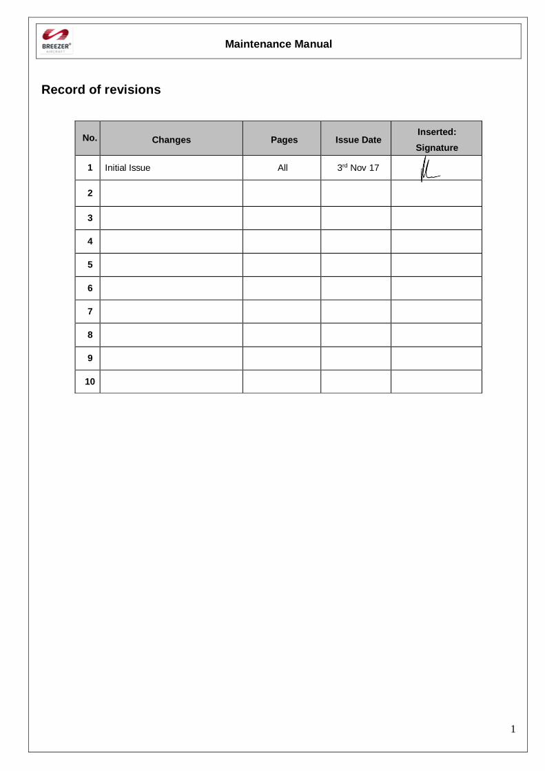
Record of revisions
No. Changes Pages Issue Date Inserted:
Signature
1 Initial Issue All 3rd Nov 17
2
3
4
5
6
7
8
9
10
Maintenance Manual
2
Table of Contents
Table of Contents........................................................................................................................................ 2
1. General Information ............................................................................................................................ 6
2. Introduction ........................................................................................................................................ 7
3. Safety notice ....................................................................................................................................... 8
Additional Notes and Warning information ............................................................................................. 8
4. Conversion table ................................................................................................................................. 9
5. Technical data ................................................................................................................................... 10
6. Options list........................................................................................................................................ 12
7. List of disposable replacement parts .................................................................................................. 12
8. Engine specification .......................................................................................................................... 13
9. Weight & Balance Information ......................................................................................................... 16
10. Tyre inflation pressure ................................................................................................................... 16
................................................................................................................................................................. 16
11. Approved Oils & Capacities ........................................................................................................... 16
Oil specification .................................................................................................................................... 16
12. Oil capacity .................................................................................................................................... 17
Oil viscosity .......................................................................................................................................... 17
13. Recommended fastener torque values ............................................................................................. 17
14. Specific fastener torque values ....................................................................................................... 18
Reporting possible safety of flight concerns .......................................................................................... 19
15. Inspections ..................................................................................................................................... 19
Pre-flight inspection .............................................................................................................................. 19
Cabin inspection ................................................................................................................................... 19
Walk-around inspection ........................................................................................................................ 21
Periodic Maintenance and Inspection .................................................................................................... 26
Basic Inspection .................................................................................................................................... 26
25 hours Inspection ............................................................................................................................... 29
50 hours Inspection ............................................................................................................................... 29
100 hours Inspection ............................................................................................................................. 30
Further periodic maintenance ................................................................................................................ 30
Interval tolerances ................................................................................................................................. 30
16. Lubrication plan ............................................................................................................................. 31
17. Unscheduled Maintenance checks (Special checks) ........................................................................ 34
General ................................................................................................................................................. 34
Hard landing ......................................................................................................................................... 34
Violent Stop of the Engine .................................................................................................................... 36
G-load exceedance ................................................................................................................................ 36
Maintenance Manual
3
Speed limits exceedance ....................................................................................................................... 36
Structure ............................................................................................................................................... 38
DISASSEMBLING / ASSEMBLING the wing ..................................................................................... 39
Empennage ........................................................................................................................................... 42
Assembling the empennage ................................................................................................................... 43
Levelling the horizontal stabilizer ......................................................................................................... 45
Disassembling the empennage .............................................................................................................. 46
Landing gear ......................................................................................................................................... 47
Main landing gear ................................................................................................................................. 48
Disassembling/Assembling the wheel fairing ........................................................................................ 48
Disassembling/Assembling the wheel ................................................................................................... 49
Procedure to change tyre ....................................................................................................................... 52
Disassembling/Assembling the axle and calliper ................................................................................... 53
Disassembling/Assembling the main landing gear leg ........................................................................... 54
Nose landing gear ................................................................................................................................. 56
Disassembling / Assembling the nose wheel fairing ............................................................................. 58
Disassembling / Assembling the nose landing wheel ............................................................................. 60
Procedure to change tyre ....................................................................................................................... 61
Disassembling / Assembling the nose landing gear leg .......................................................................... 62
Brake system ........................................................................................................................................ 64
Parking brake ........................................................................................................................................ 65
Brake –main wheel ............................................................................................................................... 66
Brake system bleeding procedure .......................................................................................................... 67
Change of brake pads ............................................................................................................................ 69
18. Flight controls and control surfaces ................................................................................................ 72
General ................................................................................................................................................. 72
Overview - control surface deflection.................................................................................................... 72
Disassembling / Assembling of the flight controls ................................................................................. 73
Aileron ................................................................................................................................................. 75
Checking operation and deflection of the aileron control assembly........................................................ 76
Wing flap control .................................................................................................................................. 78
Elevators ............................................................................................................................................... 80
Checking operation and deflection of the elevator control assembly ...................................................... 80
Rudder .................................................................................................................................................. 83
Operation and deflection check of the rudder control assembly ............................................................. 86
Trim...................................................................................................................................................... 88
19. Front turtle deck ............................................................................................................................. 92
Installation ............................................................................................................................................ 94
Maintenance Manual
4
20. Powerplant ..................................................................................................................................... 95
General ................................................................................................................................................. 95
Engine Specifications ............................................................................................................................ 95
21. Engine cooling system ................................................................................................................. 102
General ............................................................................................................................................... 102
Mounting - radiator ............................................................................................................................. 103
Engine lubrication system ................................................................................................................... 104
22. Air filters ..................................................................................................................................... 106
General ............................................................................................................................................... 106
Removal / installation ......................................................................................................................... 107
Components & Sensors ....................................................................................................................... 108
23. Exhaust system ............................................................................................................................ 111
General ............................................................................................................................................... 111
24. Inspection, Removal and installation of engine components ......................................................... 112
Exhaust system ................................................................................................................................... 112
Installation .......................................................................................................................................... 113
Engine removal / installation ............................................................................................................... 115
25. Operating materials ...................................................................................................................... 117
Cooling liquid ..................................................................................................................................... 117
Lubrication ......................................................................................................................................... 117
Fuel .................................................................................................................................................... 118
26. FUEL SYSTEM ........................................................................................................................... 119
General ............................................................................................................................................... 119
Fuel tank ............................................................................................................................................. 122
Electric fuel pump ............................................................................................................................... 123
Fuel sender ......................................................................................................................................... 123
Instruments & Avionics ...................................................................................................................... 133
Laying the wiring ................................................................................................................................ 144
Firewall – Engine compartment .......................................................................................................... 145
3-in-1 NAV/Position/Strobe ................................................................................................................ 150
27. Wiring diagram ............................................................................................................................ 152
General ............................................................................................................................................... 152
Wiring diagram ................................................................................................................................... 152
28. Structural repairs .......................................................................................................................... 155
General ............................................................................................................................................... 155
Rivets ................................................................................................................................................. 155
Removing rivets .................................................................................................................................. 155
Riveting .............................................................................................................................................. 157
Maintenance Manual
5
Skin repairs ......................................................................................................................................... 158
Remove damaged skins ....................................................................................................................... 158
Principles for repair method determination .......................................................................................... 158
Stopping cracks................................................................................................................................... 159
Repair of fiberglass parts .................................................................................................................... 159
Small damages of forming parts .......................................................................................................... 160
Torque moments ................................................................................................................................. 160
Bolt joint securing by locking wire...................................................................................................... 161
Nicopress crimping ............................................................................................................................. 162
29. Painting / Cleaning / Preservation................................................................................................. 165
Painting .............................................................................................................................................. 165
Cleaning ............................................................................................................................................. 166
Airplane preparation ........................................................................................................................... 167
30. Aircraft parts life limitations ........................................................................................................ 169
[Intentionally left blank]
Maintenance Manual
6
1. General Information
Contact information & sources to purchase parts:
Type approval holder: Breezer Aviation
Engine Manufacturer: BRP-Powertrain GmbH & Co. KG
Detailed and up to date information on authorised Rotax dealers can be found on the official manufacturer website at www.flyrotax.com.
.
Propeller manufacturer: DUC France and Woodcomp, CZ
Sources to purchase parts: Breezer Aviation. www.breezeraviation.co.uk
Maintenance Manual
7
2. Introduction
It is vital that this manual is read in conjunction with the Pilot Operators Handbook (POH) that was issued with the aircraft. The POH contains all important data that relates to operating weights and limitations of that particular aircraft. This handbook covers maintenance, servicing and other items that relate to aircraft sold in more than one country and aircraft that have differing limitations.
If you do not have the POH of the aircraft that requires maintenance do not proceed until this document is available. It can be obtained directly from Breezer Aviation, UK.
SERIOUS INJURY OR DEATH MAY RESULT FROM THE INCORRECT APPLICATION OF THIS MANUAL.
The information given in the Maintenance Manual is based on data and experience, which are considered to be applicable for a skilled mechanic under normal working conditions.
This maintenance manual provides to maintenance personnel all information necessary for the maintenance of the Breezer B400. It contains detailed descriptions of the systems, troubleshooting and maintenance practices.
This handbook only contains maintenance practices to be carried out on the aircraft, e.g. removal and installation of components.
Maintenance, repairs and inspections must be accomplished in accordance with the instructions given in this Maintenance Manual (MM).
Note:
We particularly emphasize that parts and accessories not supplied as genuine Breezer Aviation parts are not verified for suitability by Breezer Aviation and thus are not authorized for use.
Installation and/or use of such products may possibly change or negatively influence the operational characteristics of the Breezer. For damages resulting from use of non-genuine parts
and accessories Breezer Aviation refuses any liability.
Non-authorized modifications as well as the use of components and auxiliary components not corresponding to the installation instructions exclude any liability by the aircraft manufacturer.
Before carrying out maintenance work on the Breezer, carefully read the Maintenance Manual – if any passages of the Manual are not clearly understood or in case of any question, please
contact an authorized Service- or Distribution Centre for Breezer Aviation Products.
Maintenance Manual
8
3. Safety notice
This manual has been prepared as a guide to correctly service and maintain the Breezer B400.
This edition was primarily published to be used by aircraft mechanics that are already familiar with all service procedures relating to the Breezer.
Please note that the instructions will apply only if proper hand tools and special service tools are used.
Torque wrench tightening specifications must be strictly adhered to. Locking devices must be installed or replaced with new ones, where specified. If the efficiency of a locking device is impaired, it must be renewed.
It is your responsibility to be completely familiar with the safety instructions and technical terms described in this manual. Non-observance of the described procedures can cause a serious malfunction, which can result in loss of live.
It is, however, important to understand that these manual incl. safety notices and warnings are not exhaustive. Breezer Aviation could not possibly know, evaluate and advise the user of all conceivable ways in which service might be done or of the possible hazardous consequences of each way. Although the mere reading of such information does not eliminate the hazard, your understanding of the information will promote its correct use. Always use common shop safety practice.
Additional Notes and Warning information
Note
The given information is considered to be important for the accomplishment of the described maintenance task or part of the manual.
Caution
Means that non-observation of the given instructions can lead to damage or destruction of the aircraft or parts of it.
Maintenance Manual
9
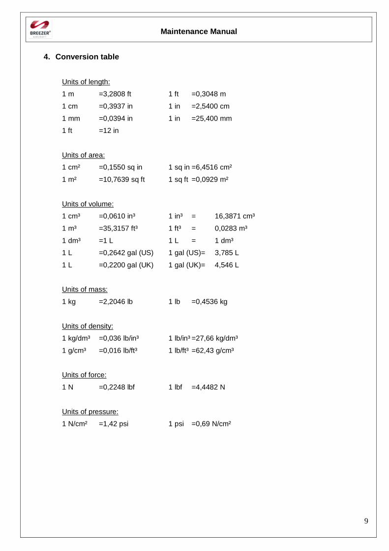
4. Conversion table
Units of length:
1 m =3,2808 ft 1 ft =0,3048 m
1 cm =0,3937 in 1 in =2,5400 cm
1 mm =0,0394 in 1 in =25,400 mm
1 ft =12 in
Units of area:
1 cm² =0,1550 sq in 1 sq in =6,4516 cm²
1 m² =10,7639 sq ft 1 sq ft =0,0929 m²
Units of volume:
1 cm³ =0,0610 in³ 1 in³ = 16,3871 cm³
1 m³ =35,3157 ft³ 1 ft³ = 0,0283 m³
1 dm³ =1 L 1 L = 1 dm³
1 L =0,2642 gal (US) 1 gal (US)= 3,785 L
1 L =0,2200 gal (UK) 1 gal (UK)= 4,546 L
Units of mass:
1 kg =2,2046 lb 1 lb =0,4536 kg
Units of density:
1 kg/dm³ =0,036 lb/in³ 1 lb/in³ =27,66 kg/dm³
1 g/cm³ =0,016 lb/ft³ 1 lb/ft³ =62,43 g/cm³
Units of force:
1 N =0,2248 lbf 1 lbf =4,4482 N
Units of pressure:
1 N/cm² =1,42 psi 1 psi =0,69 N/cm²
Maintenance Manual
10
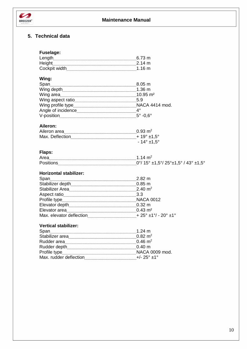
5. Technical data
Fuselage:
Length 6.73 m Height 2.14 m Cockpit width 1.16 m Wing:
Span 8.05 m Wing depth 1.36 m Wing area 10.95 m² Wing aspect ratio 5.9 Wing profile type NACA 4414 mod. Angle of incidence 4° V-position 5° -0,6° Aileron: Aileron area 0.93 m2
Max. Deflection + 19° ±1,5° - 14° ±1,5°
Flaps:
Area 1.14 m2
Positions 0°/ 15° ±1,5°/ 25°±1,5° / 43° ±1,5° Horizontal stabilizer:
Span 2.82 m Stabilizer depth 0.85 m Stabilizer Area 2.40 m2
Aspect ratio 3.3 Profile type NACA 0012 Elevator depth 0.32 m Elevator area 0.43 m² Max. elevator deflection + 25° ±1°/ - 20° ±1° Vertical stabilizer:
Span 1.24 m Stabilizer area 0.82 m2 Rudder area 0.46 m2 Rudder depth 0.40 m Profile type NACA 0009 mod. Max. rudder deflection +/- 25° ±1°
Maintenance Manual
11
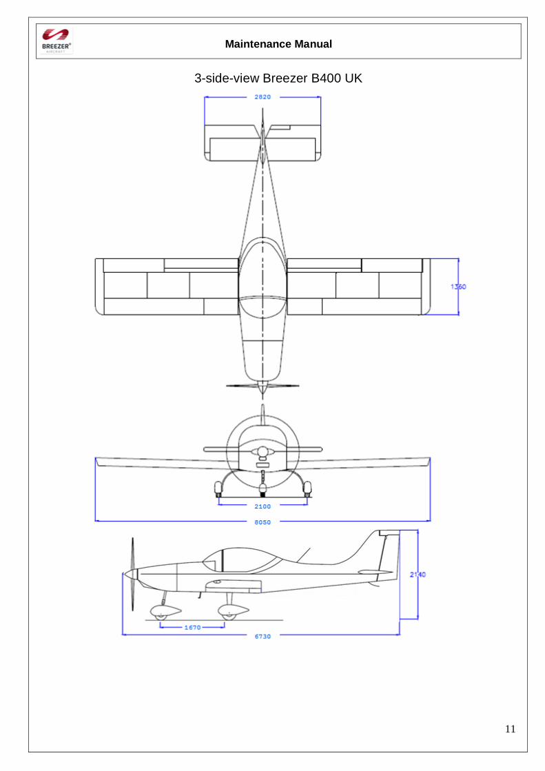
3-side-view Breezer B400 UK
Maintenance Manual
12
6. Options list
The up to date options list can be found in the current version of the CAA HADS.
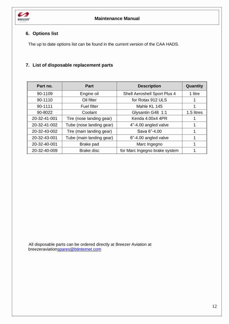
7. List of disposable replacement parts
All disposable parts can be ordered directly at Breezer Aviation at [email protected]
Part no. Part Description Quantity
90-1109 Engine oil Shell Aeroshell Sport Plus 4 1 litre
90-1110 Oil filter for Rotax 912 ULS 1
90-1111 Fuel filter Mahle KL 145 1
90-8022 Coolant Glysantin G48 1:1 1.5 litres
20-32-41-001 Tire (nose landing gear) Kenda 4.00x4 4PR 1
20-32-41-002 Tube (nose landing gear) 4”-4.00 angled valve 1
20-32-43-002 Tire (main landing gear) Sava 6”-4.00 1
20-32-43-001 Tube (main landing gear) 6”-4.00 angled valve 1
20-32-40-001 Brake pad Marc Ingegno 1
20-32-40-009 Brake disc for Marc Ingegno brake system 1
Maintenance Manual
13
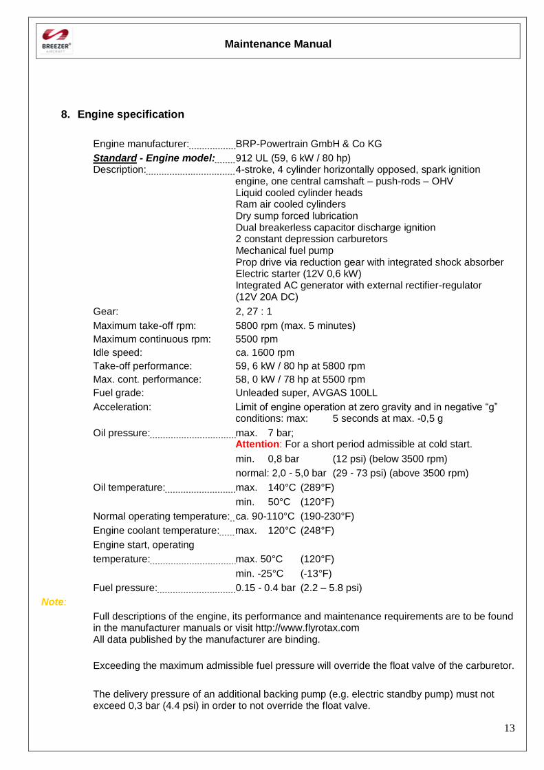
8. Engine specification
Engine manufacturer: BRP-Powertrain GmbH & Co KG
Standard - Engine model: 912 UL (59, 6 kW / 80 hp) Description: 4-stroke, 4 cylinder horizontally opposed, spark ignition
engine, one central camshaft – push-rods – OHV Liquid cooled cylinder heads Ram air cooled cylinders Dry sump forced lubrication Dual breakerless capacitor discharge ignition 2 constant depression carburetors Mechanical fuel pump
Prop drive via reduction gear with integrated shock absorber Electric starter (12V 0,6 kW) Integrated AC generator with external rectifier-regulator
(12V 20A DC)
Gear: 2, 27 : 1
Maximum take-off rpm: 5800 rpm (max. 5 minutes)
Maximum continuous rpm: 5500 rpm
Idle speed: ca. 1600 rpm
Take-off performance: 59, 6 kW / 80 hp at 5800 rpm
Max. cont. performance: 58, 0 kW / 78 hp at 5500 rpm
Fuel grade: Unleaded super, AVGAS 100LL
Acceleration: Limit of engine operation at zero gravity and in negative “g” conditions: max: 5 seconds at max. -0,5 g
Oil pressure: max. 7 bar; Attention: For a short period admissible at cold start.
min. 0,8 bar (12 psi) (below 3500 rpm)
normal: 2,0 - 5,0 bar (29 - 73 psi) (above 3500 rpm)
Oil temperature: max. 140°C (289°F)
min. 50°C (120°F)
Normal operating temperature: ca. 90-110°C (190-230°F)
Engine coolant temperature: max. 120°C (248°F)
Engine start, operating
temperature: max. 50°C (120°F)
min. -25°C (-13°F)
Fuel pressure: 0.15 - 0.4 bar (2.2 – 5.8 psi)
Note:
Full descriptions of the engine, its performance and maintenance requirements are to be found in the manufacturer manuals or visit http://www.flyrotax.com All data published by the manufacturer are binding.
Exceeding the maximum admissible fuel pressure will override the float valve of the carburetor.
The delivery pressure of an additional backing pump (e.g. electric standby pump) must not exceed 0,3 bar (4.4 psi) in order to not override the float valve.
Maintenance Manual
14
Maintenance Manual
15
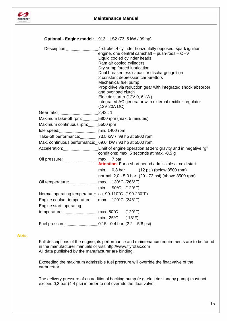
Optional - Engine model: 912 ULS2 (73, 5 kW / 99 hp)
Description: 4-stroke, 4 cylinder horizontally opposed, spark ignition engine, one central camshaft – push-rods – OHV
Liquid cooled cylinder heads Ram air cooled cylinders Dry sump forced lubrication Dual breaker less capacitor discharge ignition 2 constant depression carburettors Mechanical fuel pump
Prop drive via reduction gear with integrated shock absorber and overload clutch
Electric starter (12V 0, 6 kW) Integrated AC generator with external rectifier-regulator (12V 20A DC)
Gear ratio: 2,43 : 1
Maximum take-off rpm: 5800 rpm (max. 5 minutes)
Maximum continuous rpm: 5500 rpm
Idle speed: min. 1400 rpm
Take-off performance: 73,5 kW / 99 hp at 5800 rpm
Max. continuous performance: 69,0 kW / 93 hp at 5500 rpm
Acceleration: Limit of engine operation at zero gravity and in negative “g” conditions: max: 5 seconds at max. -0,5 g
Oil pressure: max. 7 bar Attention: For a short period admissible at cold start.
min. 0,8 bar (12 psi) (below 3500 rpm)
normal: 2,0 - 5,0 bar (29 - 73 psi) (above 3500 rpm)
Oil temperature: max. 130°C (266°F)
min. 50°C (120°F)
Normal operating temperature: ca. 90-110°C (190-230°F)
Engine coolant temperature: max. 120°C (248°F)
Engine start, operating
temperature: max. 50°C (120°F)
min. -25°C (-13°F)
Fuel pressure: 0.15 - 0.4 bar (2.2 – 5.8 psi)
Note:
Full descriptions of the engine, its performance and maintenance requirements are to be found in the manufacturer manuals or visit http://www.flyrotax.com All data published by the manufacturer are binding.
Exceeding the maximum admissible fuel pressure will override the float valve of the carburettor.
The delivery pressure of an additional backing pump (e.g. electric standby pump) must not exceed 0,3 bar (4.4 psi) in order to not override the float valve.
Maintenance Manual
16
9. Weight & Balance Information
Please refer to the POH in the current revision for weight and balance information.
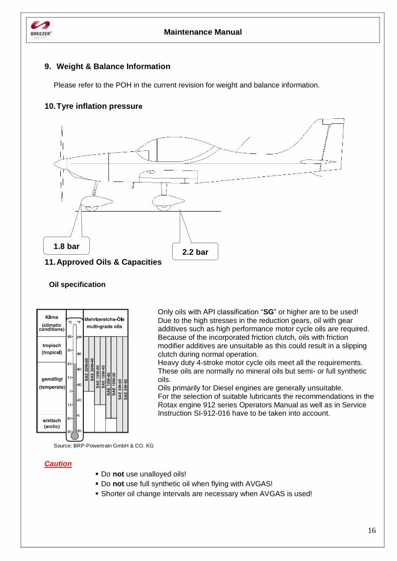
10. Tyre inflation pressure
11. Approved Oils & Capacities
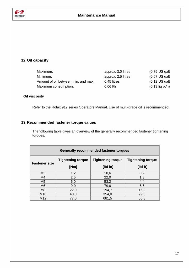
Oil specification
Only oils with API classification “SG” or higher are to be used!
Due to the high stresses in the reduction gears, oil with gear additives such as high performance motor cycle oils are required. Because of the incorporated friction clutch, oils with friction modifier additives are unsuitable as this could result in a slipping clutch during normal operation. Heavy duty 4-stroke motor cycle oils meet all the requirements. These oils are normally no mineral oils but semi- or full synthetic oils. Oils primarily for Diesel engines are generally unsuitable. For the selection of suitable lubricants the recommendations in the Rotax engine 912 series Operators Manual as well as in Service Instruction SI-912-016 have to be taken into account.
Source: BRP-Powertrain GmbH & CO. KG
Caution
Do not use unalloyed oils!
Do not use full synthetic oil when flying with AVGAS!
Shorter oil change intervals are necessary when AVGAS is used!
1.8 bar 2.2 bar
Maintenance Manual
17
12. Oil capacity
Maximum: approx. 3,0 litres (0,79 US gal)
Minimum: approx. 2,5 litres (0,67 US gal)
Amount of oil between min. and max.: 0,45 litres (0,12 US gal)
Maximum consumption: 0,06 l/h (0,13 liq pt/h)
Oil viscosity
Refer to the Rotax 912 series Operators Manual. Use of multi-grade oil is recommended.
13. Recommended fastener torque values
The following table gives an overview of the generally recommended fastener tightening torques.
Generally recommended fastener torques
Fastener size Tightening torque
[Nm]
Tightening torque
[lbf in]
Tightening torque
[lbf ft]
M3 1,2 10,6 0,9
M4 2,5 22,0 1,8
M5 6,0 53,2 4,4
M6 9,0 79,6 6,6
M8 22,0 194,7 16,2
M10 40,0 354,0 29,5
M12 77,0 681,5 56,8

Maintenance Manual
18
14. Specific fastener torque values
In addition the following table gives an overview of the fasteners for which the tightening torques differ from the general recommendations.
Caution
These specific tightening torque values are binding and have to be taken into account.
Specific fastener torques
Description Qty. Fastener
size
Tightening torque
[Nm]
Tightening torque
[lbf in]
Tightening torque
[lbf ft]
Main landing gear wheel assembly
8 M6 10,0 88,5 7,4
Attachment of ring mount to engine mount
4 M10 35,0 309,8 25,8
Attachment of water cooler to engine
2 M10 35,0 309,8 25,8
Water thermostat case 2 M6 8,0 70,8 5,9
Attachment of oil cooler to gear box
1 M10 35,0 309,8 25,8
Swivel nuts of oil hoses at oil cooler
2 - 25,0 221,3 18,4
Attachment of oil thermostat to oil cooler
4 M5 8,0 70,8 5,9
Manifold attachment 8 M8 12,0 106,2 8,9
Aileron bearing 6 M5 1,5 – 2,0 13,3 – 17,7 1,1 – 1,5
Elevator bearing 4 M5 1,5 – 2,0 13,3 – 17,7 1,1 – 1,5
Rudder bearing 2 M5 1,5 – 2,0 13,3 – 17,7 1,1 – 1,5
Wing bellcrank 2 M5 1,5 – 2,0 13,3 – 17,7 1,1 – 1,5
Attachment of rescue system clamps
4 M8 25,0 221,3 18,4
Maintenance Manual
19
Reporting possible safety of flight concerns
Any defects, problems or abnormalies found during inspections or maintenance that can have an impact on the safety of flight have to be reported to Breezer Aviation. A corresponding feedback form can be found in chapter XII of this manual.
15. Inspections
Pre-flight inspection
A pre-flight inspection has to be undertaken before each flight. The inspection consists of two parts: A cabin inspection as well as a walk-around inspection of the aircraft. It is for your own safety and all points should be carried out appropriately. In this way, small defects may be discovered and removed on time.
Note:
It is the responsibility of the owner / pilot to establish appropriate safety and health practices and determine the applicability of regulatory requirements prior to use.
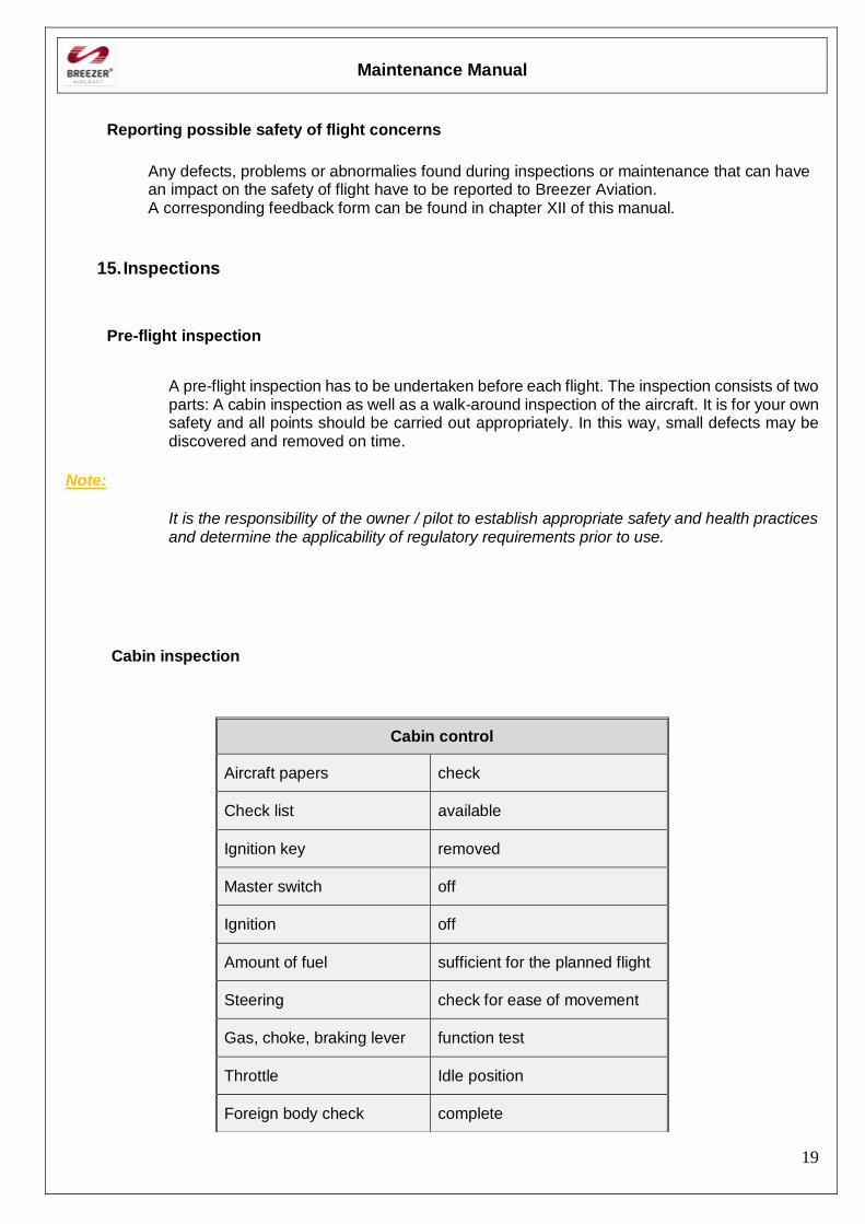
Cabin inspection
Cabin control
Aircraft papers check
Check list available
Ignition key removed
Master switch off
Ignition off
Amount of fuel sufficient for the planned flight
Steering check for ease of movement
Gas, choke, braking lever function test
Throttle Idle position
Foreign body check complete
Maintenance Manual
20
Baggage stored and secured
Maintenance Manual
21
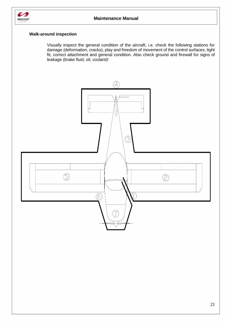
Walk-around inspection
Visually inspect the general condition of the aircraft, i.e. check the following stations for damage (deformation, cracks), play and freedom of movement of the control surfaces, tight fit, correct attachment and general condition. Also check ground and firewall for signs of leakage (brake fluid, oil, coolant)!
Maintenance Manual
22
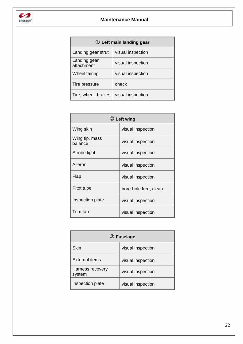
Left main landing gear
Landing gear strut visual inspection
Landing gear attachment
visual inspection
Wheel fairing visual inspection
Tire pressure check
Tire, wheel, brakes visual inspection
Left wing
Wing skin visual inspection
Wing tip, mass balance visual inspection
Strobe light visual inspection
Aileron visual inspection
Flap visual inspection
Pitot tube bore-hole free, clean
Inspection plate visual inspection
Trim tab visual inspection
Fuselage
Skin visual inspection
External items visual inspection
Harness recovery system
visual inspection
Inspection plate visual inspection
Maintenance Manual
23
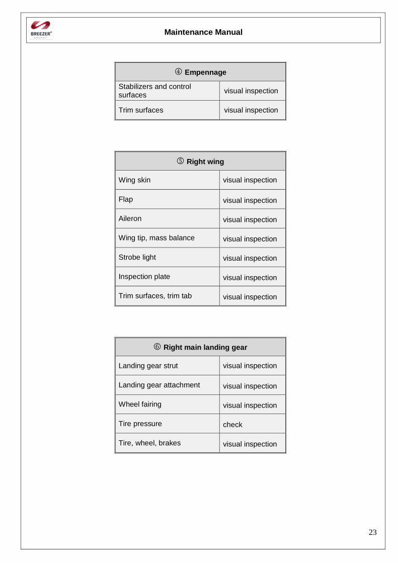
Empennage
Stabilizers and control surfaces
visual inspection
Trim surfaces visual inspection
Right wing
Wing skin visual inspection
Flap visual inspection
Aileron visual inspection
Wing tip, mass balance visual inspection
Strobe light visual inspection
Inspection plate visual inspection
Trim surfaces, trim tab visual inspection
Right main landing gear
Landing gear strut visual inspection
Landing gear attachment visual inspection
Wheel fairing visual inspection
Tire pressure check
Tire, wheel, brakes visual inspection
Maintenance Manual
24
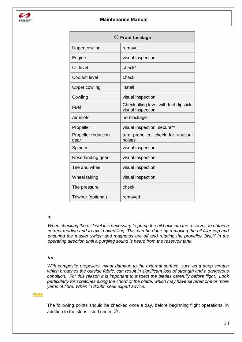
Front fuselage
Upper cowling remove
Engine visual inspection
Oil level check*
Coolant level check
Upper cowling install
Cowling visual inspection
Fuel Check filling level with fuel dipstick, visual inspection
Air inlets no blockage
Propeller visual inspection, secure**
Propeller reduction gear
turn propeller, check for unusual noises
Spinner visual inspection
Nose landing gear visual inspection
Tire and wheel visual inspection
Wheel fairing visual inspection
Tire pressure check
Towbar (optional) removed
* When checking the oil level it is necessary to pump the oil back into the reservoir to obtain a correct reading and to avoid overfilling. This can be done by removing the oil filler cap and ensuring the master switch and magnetos are off and rotating the propeller ONLY in the operating direction until a gurgling sound is heard from the reservoir tank.
** With composite propellers, minor damage to the external surface, such as a deep scratch which breaches the outside fabric, can result in significant loss of strength and a dangerous condition. For this reason it is important to inspect the blades carefully before flight. Look particularly for scratches along the chord of the blade, which may have severed one or more yarns of fibre. When in doubt, seek expert advice.
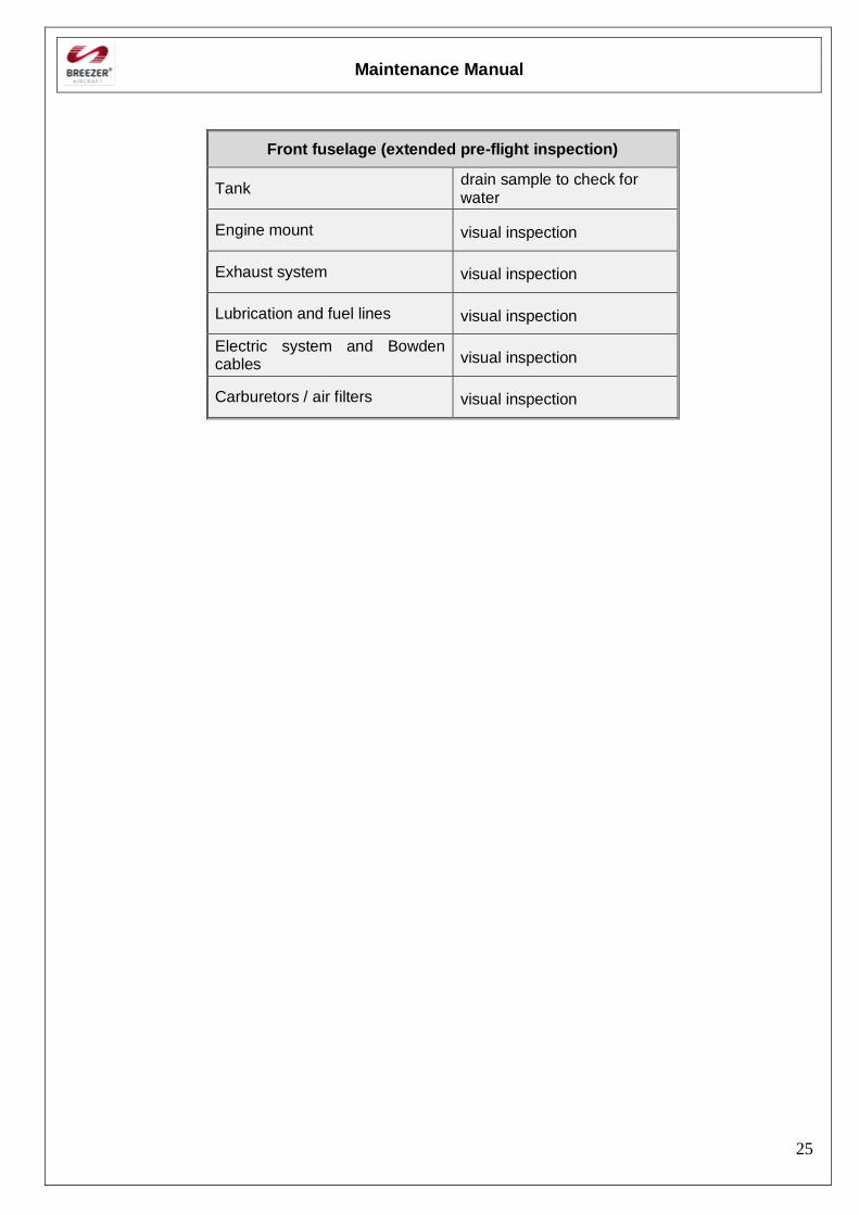
Note
The following points should be checked once a day, before beginning flight operations, in
addition to the steps listed under .
Maintenance Manual
25
Front fuselage (extended pre-flight inspection)
Tank drain sample to check for water
Engine mount visual inspection
Exhaust system visual inspection
Lubrication and fuel lines visual inspection
Electric system and Bowden cables visual inspection
Carburetors / air filters visual inspection
Maintenance Manual
26
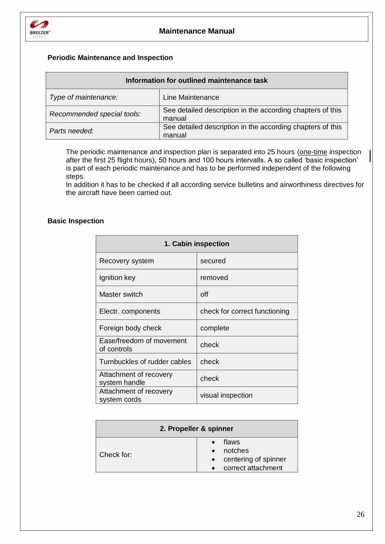
Periodic Maintenance and Inspection
Information for outlined maintenance task
Type of maintenance: Line Maintenance
Recommended special tools: See detailed description in the according chapters of this manual
Parts needed: See detailed description in the according chapters of this manual
The periodic maintenance and inspection plan is separated into 25 hours (one-time inspection after the first 25 flight hours), 50 hours and 100 hours intervalls. A so called ‘basic inspection’ is part of each periodic maintenance and has to be performed independent of the following steps. In addition it has to be checked if all according service bulletins and airworthiness directives for the aircraft have been carried out.
Basic Inspection
1. Cabin inspection
Recovery system secured
Ignition key removed
Master switch off
Electr. components check for correct functioning
Foreign body check complete
Ease/freedom of movement of controls
check
Turnbuckles of rudder cables check
Attachment of recovery system handle
check
Attachment of recovery system cords
visual inspection
2. Propeller & spinner
Check for:
flaws
notches
centering of spinner
correct attachment
Maintenance Manual
27
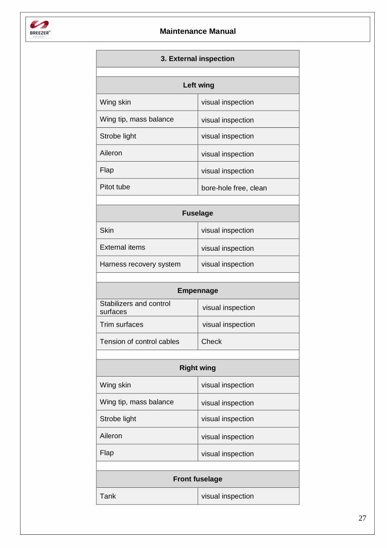
3. External inspection
Left wing
Wing skin visual inspection
Wing tip, mass balance visual inspection
Strobe light visual inspection
Aileron visual inspection
Flap visual inspection
Pitot tube bore-hole free, clean
Fuselage
Skin visual inspection
External items visual inspection
Harness recovery system visual inspection
Empennage
Stabilizers and control surfaces
visual inspection
Trim surfaces visual inspection
Tension of control cables Check
Right wing
Wing skin visual inspection
Wing tip, mass balance visual inspection
Strobe light visual inspection
Aileron visual inspection
Flap visual inspection
Front fuselage
Tank visual inspection
Maintenance Manual
28
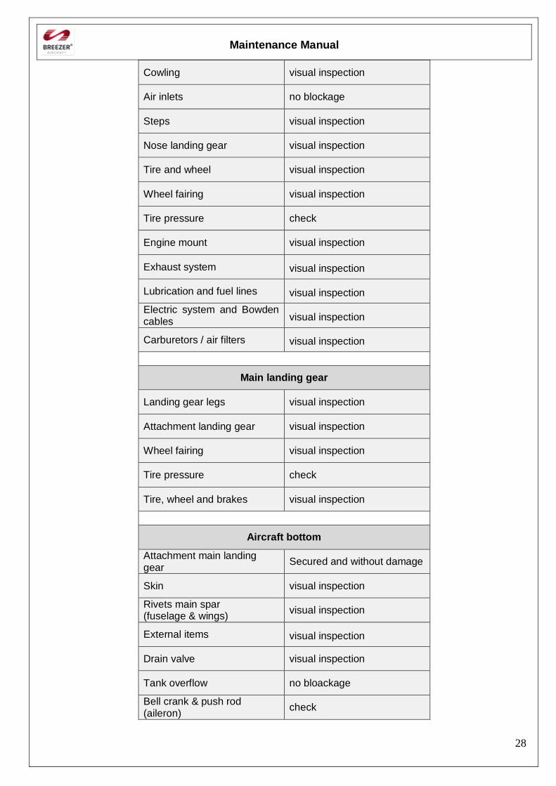
Cowling visual inspection
Air inlets no blockage
Steps visual inspection
Nose landing gear visual inspection
Tire and wheel visual inspection
Wheel fairing visual inspection
Tire pressure check
Engine mount visual inspection
Exhaust system visual inspection
Lubrication and fuel lines visual inspection
Electric system and Bowden cables visual inspection
Carburetors / air filters visual inspection
Main landing gear
Landing gear legs visual inspection
Attachment landing gear visual inspection
Wheel fairing visual inspection
Tire pressure check
Tire, wheel and brakes visual inspection
Aircraft bottom
Attachment main landing gear
Secured and without damage
Skin visual inspection
Rivets main spar (fuselage & wings)
visual inspection
External items visual inspection
Drain valve visual inspection
Tank overflow no bloackage
Bell crank & push rod (aileron)
check
Maintenance Manual
29
25 hours Inspection
(one-time inspection after the first 25 flight hours)
1. Basic inspection (see II-2.1)
2. Engine maintenance in accordance to the engine maintenance manual
3. Check pitch and attachment of the propeller
50 hours Inspection
1. Basic inspection (see II-2.1)
2. Engine maintenance in accordance to the engine maintenance manual *
3. Exchange of fuel filter **
4. Check control rods
5. Remove inspection plates at fuselage (3x) and at wings (2x) and check bell cranks for correct functioning
6. Check rudder control cables for chafe marks and proper attachment
7. Greasing in accordance to lubrication plan (see chapter II-3)
8. Check horizontal stabilizer and the vertical stabilizer spar for correct attachment
9. Visual inspection of battery
10. Check brakes for leakage, filling level of brake fluid and for correct functioning
11. Inspection within cabin:
Check freedom of movement of control torque tube
Check freedom of movement of bell crank
Check freedom of movement of control stick
Check proper attachment of wings
* If AVGAS usage > 30%
** If the aircraft was often refueled through a fuel canister
Maintenance Manual
30
100 hours Inspection
1. Complete 50 hours inspection (see II-2.3), additionally:
2. Detailed inspection of:
Weld seams on engine mount
Weld seams on nose landing gear leg
Rubber dampers on engine mount
3. Engine maintenance in accordance to the engine maintenance manual
4. Inspection of brake pads and wheel bearing
5. Check instruments and avionics for proper attachment and correct functioning
6. Check rivets at auxiliary spar inside the cabin
7. Exchange of fuel filter
Further periodic maintenance
In addition to the 25h / 50h / 100h inspections, further maintenance intervals are foreseen for the engine manufacturers. A maintenance of the engine for example has to be performed on an annual basis, independent of the amount of time the engine was running.
Refer to the engine maintenance manuals for detailed information.
Note
Please take into account possible life limitations of aircraft parts, e.g. fuel system hoses, brake fluid, etc.
These limitations can be found in chapter XIII.
Interval tolerances
The tolerances for the periodic inspection intervals of the airframe are ± 10h.
Refer to the manufacturers manuals for information about timely tolerances for the periodic engine and propeller maintenance.
Maintenance Manual
31
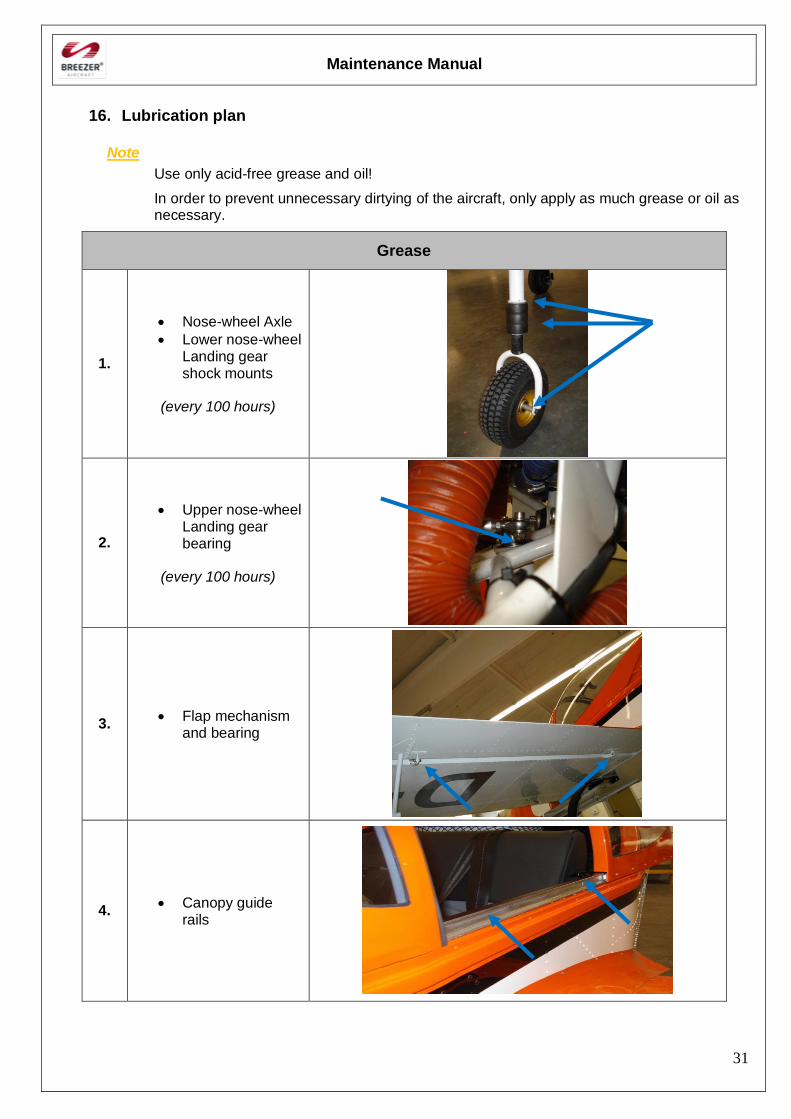
16. Lubrication plan
Note
Use only acid-free grease and oil!
In order to prevent unnecessary dirtying of the aircraft, only apply as much grease or oil as necessary.
Grease
1.
Nose-wheel Axle
Lower nose-wheel Landing gear shock mounts
(every 100 hours)
2.
Upper nose-wheel Landing gear bearing
(every 100 hours)
3. Flap mechanism
and bearing
4. Canopy guide
rails
Maintenance Manual
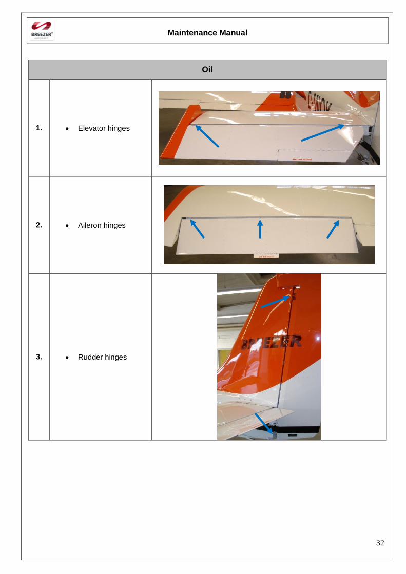
32
Oil
1. Elevator hinges
2. Aileron hinges
3. Rudder hinges
Maintenance Manual
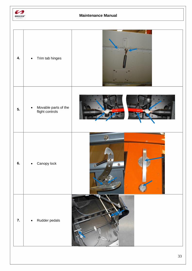
33
4. Trim tab hinges
5. Movable parts of the
flight controls
6. Canopy lock
7. Rudder pedals
Maintenance Manual
34
17. Unscheduled Maintenance checks (Special checks)
General
Special checks have to be carried out only in circumstances, outside routine inspections, where an event has occurred that may have caused damage to the aircraft or an impairment of airworthiness possibly during the operation of the aircraft. Affected parts have to be repaired or changed in case of determination of defects
Hard landing
After an excessively hard landing or other unusual loads of the landing gear a thorough inspection of the affected components and their attachment is required. Even if no obvious defects are detectable, a visual inspection must be carried out. Nose wheel Preparation: Clean the wheel fairing with water or a mild soap.
- Remove engine cowling (acc. to IV-4)
- Remove the nose wheel fairing (acc. to III.3.3.2)
- Inspect the front wheel incl. tire for damages and proper location of the slippage mark
- Inspect the axle for damages
- Inspect the engine mount incl. attachment points for deformation, stress marks and cracks
- Inspect the nose wheel fairing for damages such as cracks, dents or delaminations.
Main landing gear Preparation: Clean the landing gear / wheel fairing with water or a mild soap.
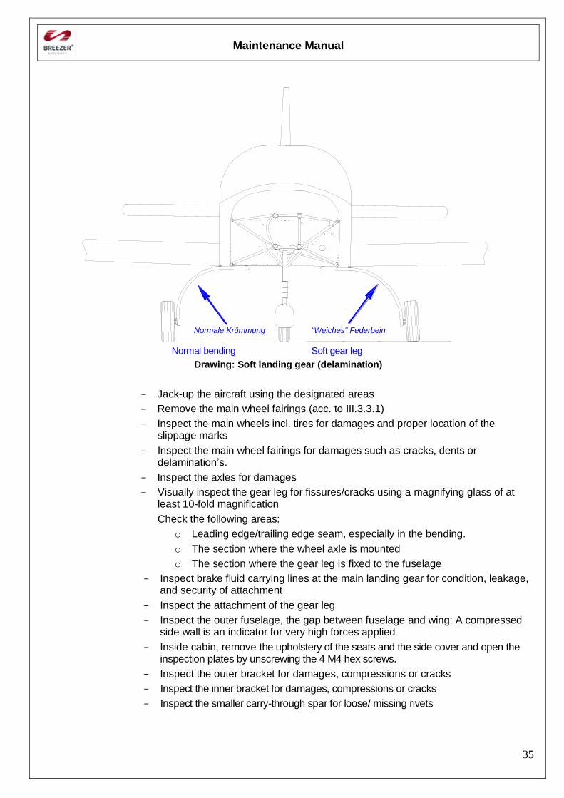
Visually check the aircraft position Delamination is indicated by a weak or soft gear and an empty aircraft usually is not parking level but slanting to one side. To inspect do the following:
- Slightly lift the aircraft at the fuselage right behind the wing to temporarily unload the landing gear.
- Push the aircraft some feet forward and reverse. Repeat this step a few times and inspect the landing gear position from the front. Check the next picture for hints to indicators.
If the landing gear remains in the wrong position (right side of the picture), the leg should be removed and send to Breezer Aviation for further inspection. REMARK: Toe-in usually is no issue in these inspections because toe-in normally is not suffering from any kind of hard landing. If you face irregular toe-in angles, please check the gear mounts very carefully
Maintenance Manual
35
Normal bending Soft gear leg
Drawing: Soft landing gear (delamination)
- Jack-up the aircraft using the designated areas
- Remove the main wheel fairings (acc. to III.3.3.1)
- Inspect the main wheels incl. tires for damages and proper location of the slippage marks
- Inspect the main wheel fairings for damages such as cracks, dents or delamination’s.
- Inspect the axles for damages
- Visually inspect the gear leg for fissures/cracks using a magnifying glass of at least 10-fold magnification
Check the following areas:
o Leading edge/trailing edge seam, especially in the bending.
o The section where the wheel axle is mounted
o The section where the gear leg is fixed to the fuselage
- Inspect brake fluid carrying lines at the main landing gear for condition, leakage, and security of attachment
- Inspect the attachment of the gear leg
- Inspect the outer fuselage, the gap between fuselage and wing: A compressed side wall is an indicator for very high forces applied
- Inside cabin, remove the upholstery of the seats and the side cover and open the inspection plates by unscrewing the 4 M4 hex screws.
- Inspect the outer bracket for damages, compressions or cracks
- Inspect the inner bracket for damages, compressions or cracks
- Inspect the smaller carry-through spar for loose/ missing rivets
Normale Krümmung "Weiches" Federbein
Maintenance Manual
36
Violent Stop of the Engine
In the event that the propeller was touching the ground or the engine was inadvertently stopped violently (shock loading) the propeller gear box must be disassembled and inspected by an authorized workshop. For further necessary inspections on the engine after the occurrence of a propeller ground strike and for more information, refer to the applicable technical documentation and to the ROTAX Maintenance Manual. Warning
Only qualified technicians (authorized by Aviation Authority and after successful Attendance of the relevant ROTAX training course) are authorized to perform this work. Check additional equipment (ignition unit, coolant and oil hoses) for damages.
G-load exceedance
In the event that the structure was overstressed during flight (gusts etc.) a thorough inspection of the affected components and their attachment is required. The following components could be affected:
- Engine mount
- Wings
- Fuselage
- Horizontal stabilizer
Proceed as follows:
- Remove engine cowling (acc. to IV-4)
- Inspect the engine mount incl. attachment points for deformation, stress marks and cracks
- Inspect the wings, fuselage and horizontal stabilizer:
o Loose/ missing rivets
o Inter-rivet buckling of the skin
o Brackets and attachments
o Bolts and screws
Speed limits exceedance
If VNE was exceeded during flight, a thorough inspection of the affected components and their attachment is required. The following components could be affected:
- Wings
- Fuselage
- Horizontal stabilizer
Proceed as follows:
- Inspect the wings, fuselage and horizontal stabilizer:
o Loose/ missing rivets
o Inter-rivet buckling of the skin
o Brackets and attachments
o Bolts and screws

Maintenance Manual
37
[Intentionally left blank]
Maintenance Manual
38
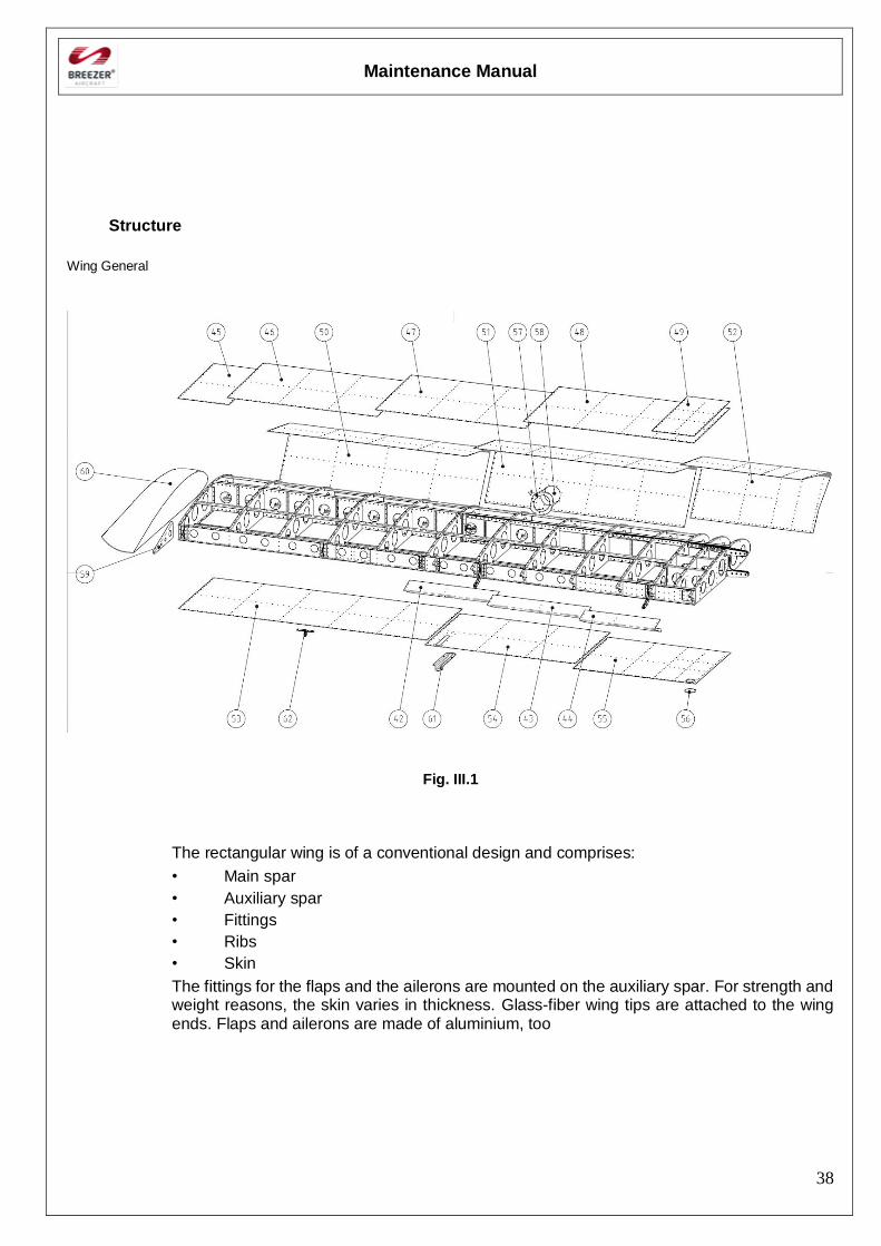
Structure
Wing General
Fig. III.1
The rectangular wing is of a conventional design and comprises:
• Main spar
• Auxiliary spar
• Fittings
• Ribs
• Skin
The fittings for the flaps and the ailerons are mounted on the auxiliary spar. For strength and weight reasons, the skin varies in thickness. Glass-fiber wing tips are attached to the wing ends. Flaps and ailerons are made of aluminium, too
Maintenance Manual
39
DISASSEMBLING / ASSEMBLING the wing
Disassembling:
Information for outlined maintenance task
Type of maintenance: Heavy Maintenance
Recommended special tools: Padded stand for storage
Parts needed: -
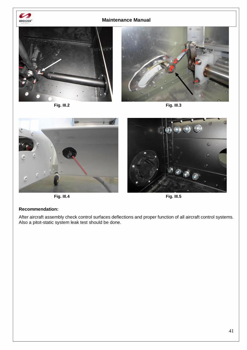
- Remove the M6 bolt of the aileron rod (Fig. III.2)
- Remove the M6 bolt of the wing flap connecting the flap with the 10 mm rod (Fig.III.3)
- Remove the M10 bolt of the rear spar of the wing (Fig.III.4)
- Remove the eight bolts of the main spar (Fig.III.5)
- Move the wing up and down carefully and pull it approx. 100 mm out of the middle section of the fuselage
- Right and left wing: Disconnect the plug of the strobe lights
- Right wing: Disconnect the plug of the aileron trim
- Left wing: Disconnect the plug of the stall warner
- Left wing: Disconnect the quick-release connector of the static-pitot tubes
- Store the wing on suitable padded stands. Be sure that they are positioned under a wing rip
Maintenance Manual
40
Assembling:
Information for outlined maintenance task
Type of maintenance: Heavy Maintenance
Recommended special tools: -
Parts needed:
Self-locking nuts
Locktite 243
Inspection lacquer
Acid-free grease
- Left wing: Connect the quick-release connector of the static-pitot tubes
- Left wing: Connect the plug of the stall warner
- Left and right wing: Connect the plug of the strobe lights
- Right wing: Connect the plug of the aileron trim
- Stow the plugs and tubes so, that they are safe and cannot be bended or chafe at the structure
- Check all systems (lights, trim, speed indication)
- Move the wing up and down carefully and let it slip into the middle section of the fuselage
- Screw on the eight bolts of the main spar. Orientation: In flight direction with the exception of the two outer bolts (Fig. III.5)
- Screw on the M10 bolt of the rear spar of the wing. Orientation: In flight direction (Fig.III.4)
- Tighten the bolts with a tightening torque of 40 Nm (354 lbs in)
Note: Do not use the lock nuts for more than 1 time!
- Screw on the M6 bolt of the wing flap (Fig.III.3)
Note: Put blue Loctite 243 on the thread of the flap linkage – not on the screw!
- Screw on the M6 bolt of the aileron rod (Fig.III.2) Orientation: Against flight direction (Fig.III.4)
- Tighten the bolts with a tightening torque of 9,0 Nm (79,6 lbs in)
Note: Replace the lock nuts!
- Use inspection lacquer for all nuts
Note: Acid-free grease should be used. In order to prevent unnecessary dirtying of the
aircraft, do not use too much grease.
Before flying, check the function and smooth running of the flight controls and flap controls carefully.
Maintenance Manual
41
Fig. III.2 Fig. III.3
Fig. III.4 Fig. III.5
Recommendation:
After aircraft assembly check control surfaces deflections and proper function of all aircraft control systems. Also a pitot-static system leak test should be done.
Maintenance Manual
42
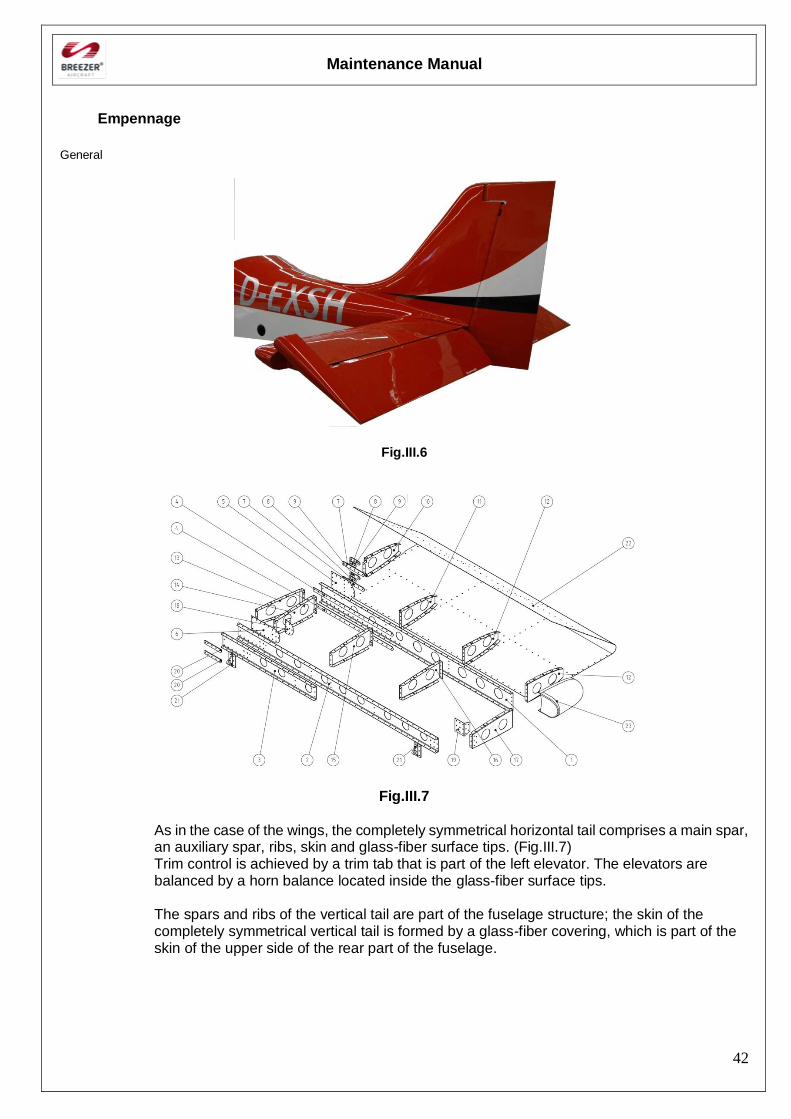
Empennage
General
Fig.III.6
Fig.III.7
As in the case of the wings, the completely symmetrical horizontal tail comprises a main spar, an auxiliary spar, ribs, skin and glass-fiber surface tips. (Fig.III.7) Trim control is achieved by a trim tab that is part of the left elevator. The elevators are balanced by a horn balance located inside the glass-fiber surface tips. The spars and ribs of the vertical tail are part of the fuselage structure; the skin of the completely symmetrical vertical tail is formed by a glass-fiber covering, which is part of the skin of the upper side of the rear part of the fuselage.
Maintenance Manual
43
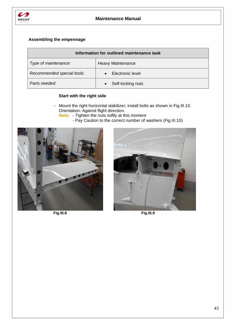
Assembling the empennage
Information for outlined maintenance task
Type of maintenance: Heavy Maintenance
Recommended special tools: Electronic level
Parts needed: Self-locking nuts
Start with the right side
- Mount the right horizontal stabilizer; install bolts as shown in Fig.III.10. Orientation: Against flight direction. Note: - Tighten the nuts softly at this moment
- Pay Caution to the correct number of washers (Fig.III.10)
Fig.III.8 Fig.III.9
Maintenance Manual
44
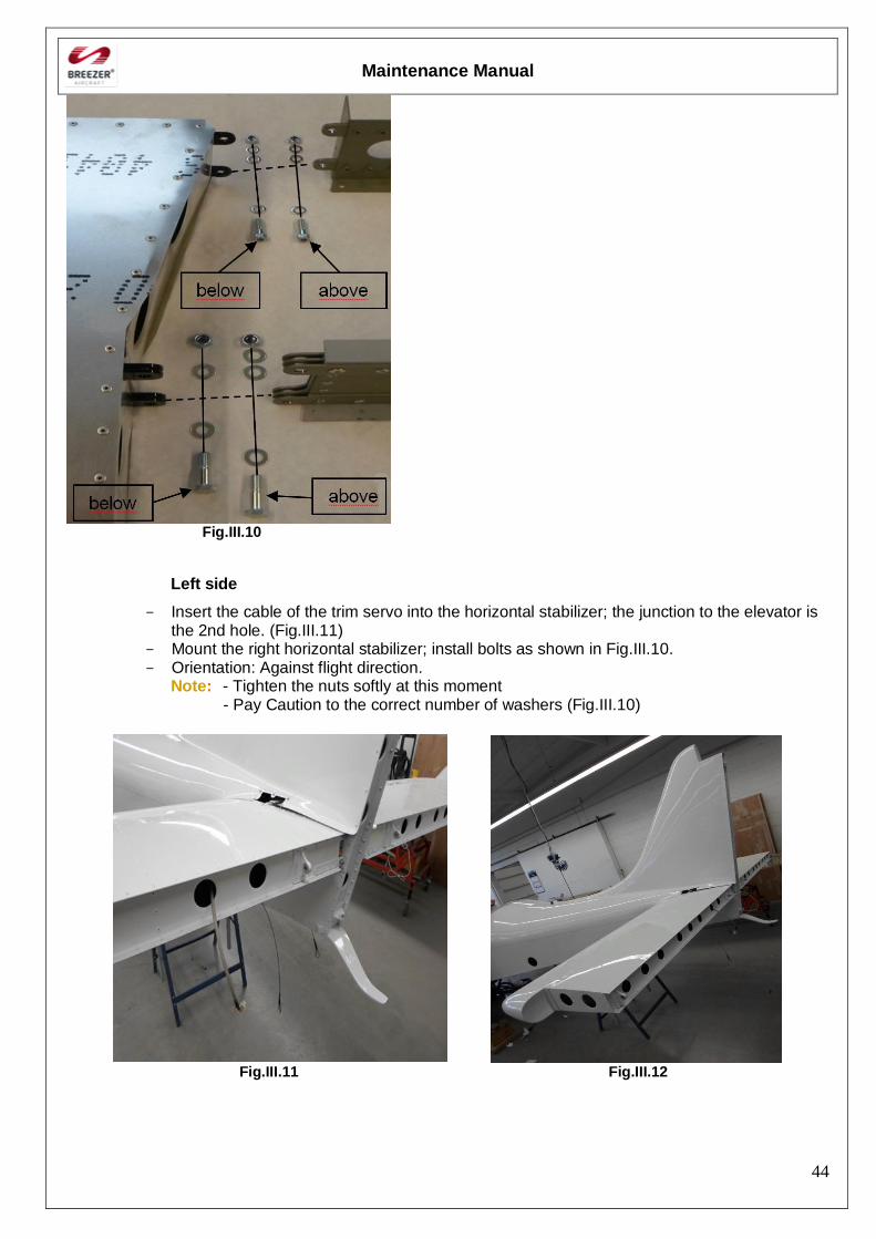
Fig.III.10
Left side
- Insert the cable of the trim servo into the horizontal stabilizer; the junction to the elevator is the 2nd hole. (Fig.III.11)
- Mount the right horizontal stabilizer; install bolts as shown in Fig.III.10. - Orientation: Against flight direction.
Note: - Tighten the nuts softly at this moment - Pay Caution to the correct number of washers (Fig.III.10)
Fig.III.11 Fig.III.12
Maintenance Manual
45
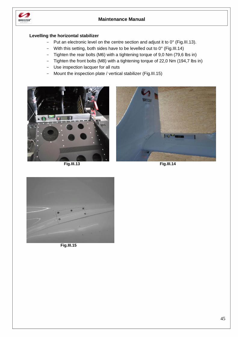
Levelling the horizontal stabilizer
- Put an electronic level on the centre section and adjust it to 0° (Fig.III.13).
- With this setting, both sides have to be levelled out to 0° (Fig.III.14)
- Tighten the rear bolts (M6) with a tightening torque of 9,0 Nm (79,6 lbs in)
- Tighten the front bolts (M8) with a tightening torque of 22,0 Nm (194,7 lbs in)
- Use inspection lacquer for all nuts
- Mount the inspection plate / vertical stabilizer (Fig.III.15)
Fig.III.13 Fig.III.14
Fig.III.15
Maintenance Manual
46
Disassembling the empennage
Information for outlined maintenance task
Type of maintenance: Heavy Maintenance
Recommended special tools: -
Parts needed: -
- Unscrew elevator (see chap. III-4.4)
- Unscrew the inspection plate
- Remove the bolts of the left horizontal stabilizer
- Disassemble the stabilizer
- Remove the bolts of the right horizontal stabilizer
- Disassemble the stabilizer

Maintenance Manual
47
Landing gear
General
The Breezer is equipped with a fixed tricycle undercarriage.
Fig.III.16
Main landing gear:
Each leg of the main landing gear is made of glass fibre. Each is fixed with four bolts at the fuselage. Nose landing gear:
The steerable nose landing gear is part of the engine mount. Rubber damper are used for shock absorbing
Maintenance Manual
48
Main landing gear
Disassembling/Assembling the wheel fairing
Information for outlined maintenance task
Type of maintenance: Line Maintenance
Recommended special tools: -
Parts needed: Loctite 243
Inspection lacquer
Zip ties
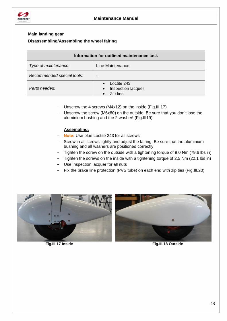
- Unscrew the 4 screws (M4x12) on the inside (Fig.III.17)
- Unscrew the screw (M6x60) on the outside. Be sure that you don’t lose the aluminium bushing and the 2 washer! (Fig.III19)
Assembling:
- Note: Use blue Loctite 243 for all screws!
- Screw in all screws lightly and adjust the fairing. Be sure that the aluminium bushing and all washers are positioned correctly
- Tighten the screw on the outside with a tightening torque of 9,0 Nm (79,6 lbs in)
- Tighten the screws on the inside with a tightening torque of 2,5 Nm (22,1 lbs in)
- Use inspection lacquer for all nuts
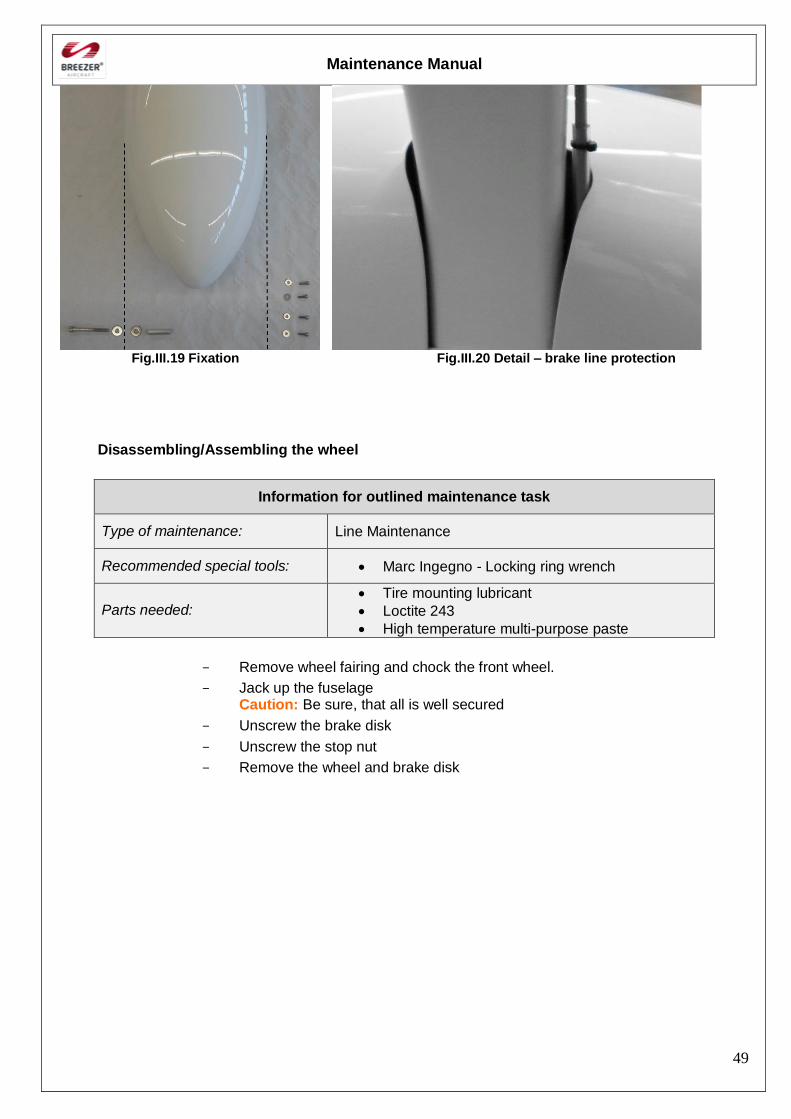
- Fix the brake line protection (PVS tube) on each end with zip ties (Fig.III.20)
Fig.III.17 Inside Fig.III.18 Outside
Maintenance Manual
49
Fig.III.19 Fixation Fig.III.20 Detail – brake line protection
Disassembling/Assembling the wheel
Information for outlined maintenance task
Type of maintenance: Line Maintenance
Recommended special tools: Marc Ingegno - Locking ring wrench
Parts needed: Tire mounting lubricant
Loctite 243
High temperature multi-purpose paste
- Remove wheel fairing and chock the front wheel.
- Jack up the fuselage Caution: Be sure, that all is well secured
- Unscrew the brake disk
- Unscrew the stop nut
- Remove the wheel and brake disk
Maintenance Manual
50
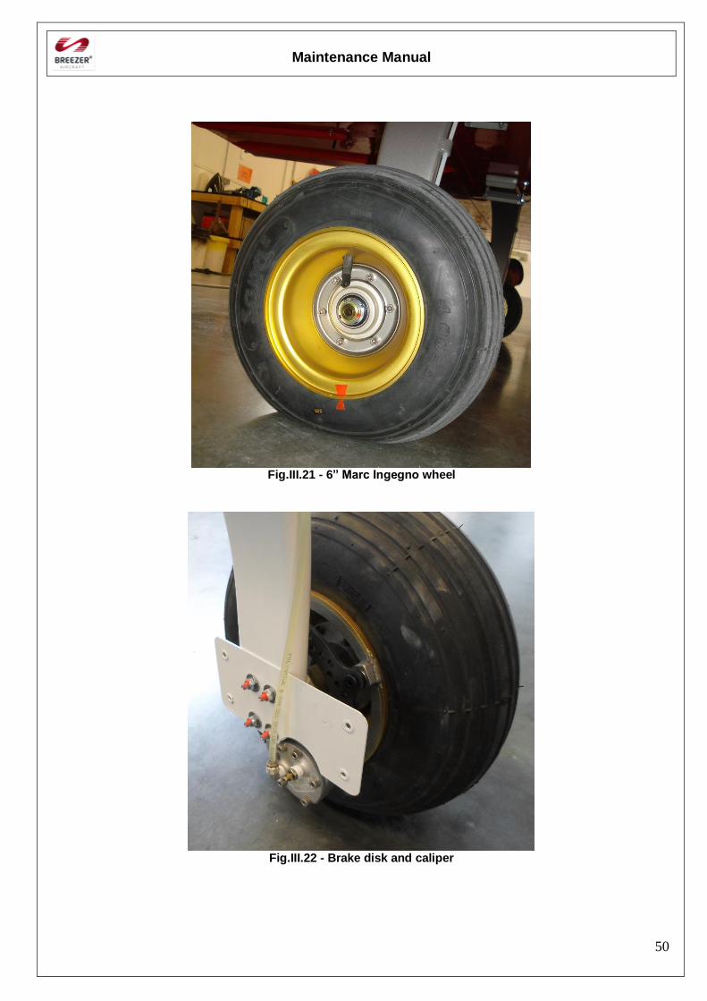
Fig.III.21 - 6” Marc Ingegno wheel
Fig.III.22 - Brake disk and caliper
Maintenance Manual
51
Assembling the wheel
- Put the brake disk between the brake pads. Do not force
- Grease copiously the axle thread
- Refit the wheel
- Screw the axle nut
- Refit the brake disk
- Grease the shank of the brake disc screws ( high temperature multi-purpose paste
- Put a spring washer on each screw
- Use blue Loctite 243 for all screws
- Screw the brake disk screws
- Tighten the screws with a tightening torque of 9,0 Nm (79,6 lbs in)
- Refit the wheel fairing
- Operate the brake to seat the brake pads in the calipers
- Caution: Before using the brake, be sure that the stopping power is sufficing
Maintenance Manual
52
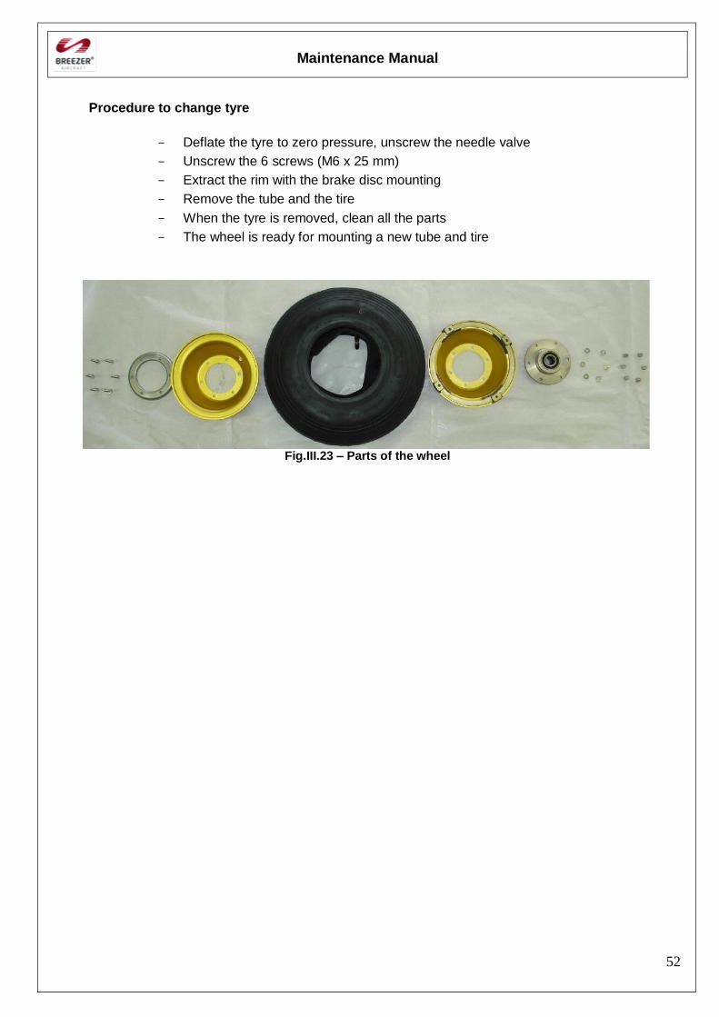
Procedure to change tyre
- Deflate the tyre to zero pressure, unscrew the needle valve
- Unscrew the 6 screws (M6 x 25 mm)
- Extract the rim with the brake disc mounting
- Remove the tube and the tire
- When the tyre is removed, clean all the parts
- The wheel is ready for mounting a new tube and tire
Fig.III.23 – Parts of the wheel
Maintenance Manual
53
Disassembling/Assembling the axle and calliper
Information for outlined maintenance task
Type of maintenance: Line Maintenance
Recommended special tools:
Parts needed: Self-locking nuts
Olives for the brake lines
DOT 4 Brake fluid
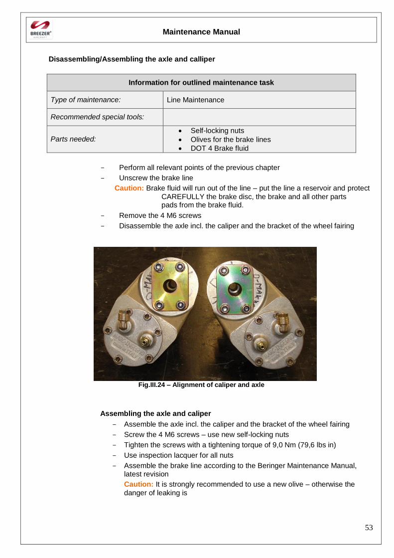
- Perform all relevant points of the previous chapter
- Unscrew the brake line
Caution: Brake fluid will run out of the line – put the line a reservoir and protect
CAREFULLY the brake disc, the brake and all other parts pads from the brake fluid.
- Remove the 4 M6 screws
- Disassemble the axle incl. the caliper and the bracket of the wheel fairing
Fig.III.24 – Alignment of caliper and axle
Assembling the axle and caliper
- Assemble the axle incl. the caliper and the bracket of the wheel fairing
- Screw the 4 M6 screws – use new self-locking nuts
- Tighten the screws with a tightening torque of 9,0 Nm (79,6 lbs in)
- Use inspection lacquer for all nuts
- Assemble the brake line according to the Beringer Maintenance Manual, latest revision
Caution: It is strongly recommended to use a new olive – otherwise the
danger of leaking is
Maintenance Manual
54
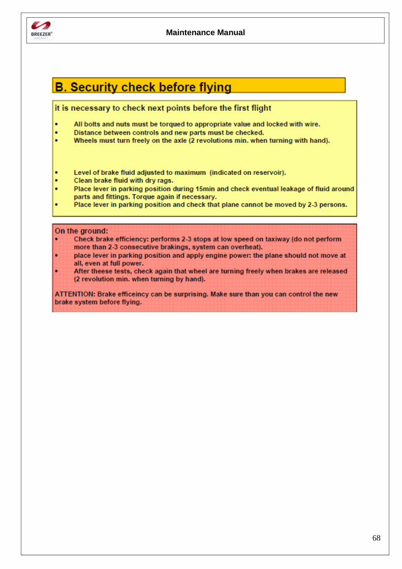
Warning: It is necessary to check next points before the first flight
- All bolts and nuts must be torqued to appropriate value and locked with wire.
- Wheels must turn freely on the axle (2 revolutions min. when turning with hand).
- Level of brake fluid adjusted to maximum (indicated on reservoir).
- Clean brake fluid with dry rags.
- Place lever in parking position during 15min and check eventual leakage of fluid around parts and fittings.
- Torque again if necessary.
- Place lever in parking position and check that plane cannot be moved by 2-3 persons.
- Check brake efficiency: performs 2-3 stops at low speed on taxiway (do not perform more than 2-3 consecutive brakings, system can overheat).
- Place lever in parking position and apply engine power: the plane should not move at all, even at full power.
- After these tests, check again that wheels are turning freely when brakes are released (2 revolution min. when turning by hand).
Disassembling/Assembling the main landing gear leg
Information for outlined maintenance task
Type of maintenance: Heavy Maintenance
Recommended special tools: -
Parts needed: Self-locking nuts
Zip ties
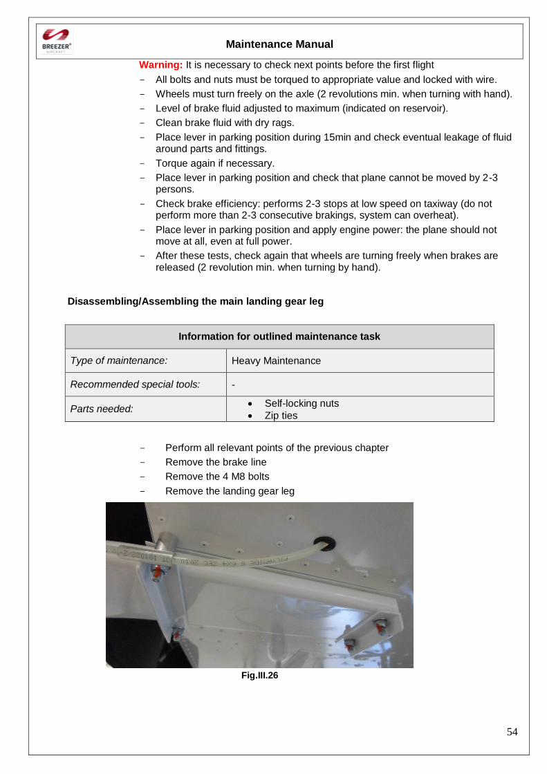
- Perform all relevant points of the previous chapter
- Remove the brake line
- Remove the 4 M8 bolts
- Remove the landing gear leg
Fig.III.26
Maintenance Manual
55
Fig.III.19
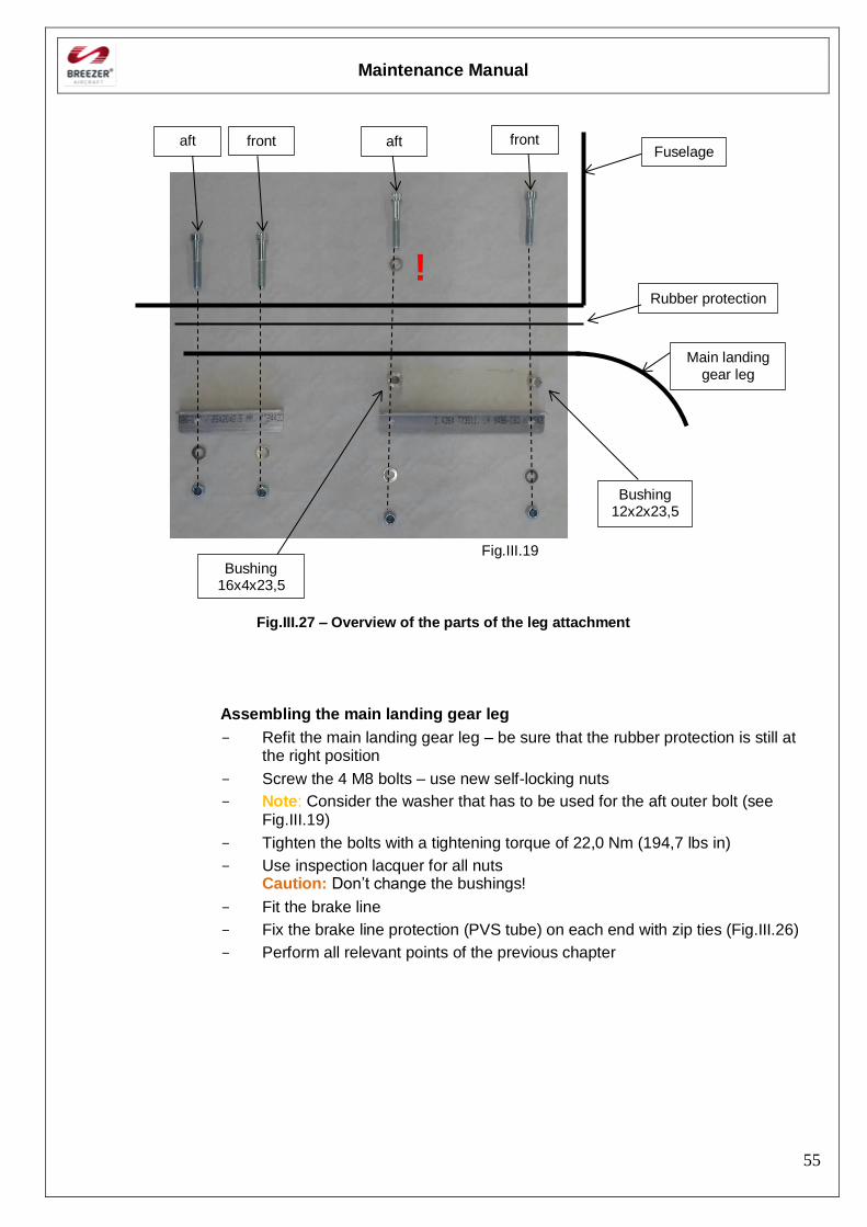
Fig.III.27 – Overview of the parts of the leg attachment
Assembling the main landing gear leg
- Refit the main landing gear leg – be sure that the rubber protection is still at the right position
- Screw the 4 M8 bolts – use new self-locking nuts
- Note: Consider the washer that has to be used for the aft outer bolt (see Fig.III.19)
- Tighten the bolts with a tightening torque of 22,0 Nm (194,7 lbs in)
- Use inspection lacquer for all nuts Caution: Don’t change the bushings!
- Fit the brake line
- Fix the brake line protection (PVS tube) on each end with zip ties (Fig.III.26)
- Perform all relevant points of the previous chapter
front aft aft front
Bushing 16x4x23,5
Bushing 12x2x23,5
Fuselage
Rubber protection
Main landing gear leg
!
Maintenance Manual
56
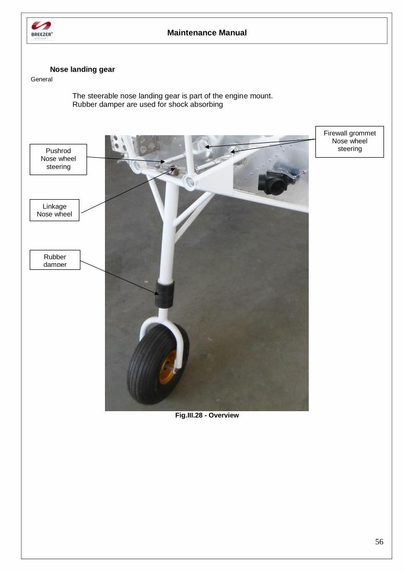
Nose landing gear
General
The steerable nose landing gear is part of the engine mount. Rubber damper are used for shock absorbing
Fig.III.28 - Overview
Pushrod Nose wheel
steering
Firewall grommet Nose wheel
steering
Linkage Nose wheel
Rubber damper

Maintenance Manual
57
Maintenance Manual
58
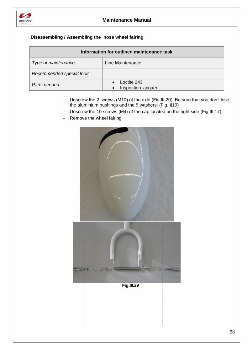
Disassembling / Assembling the nose wheel fairing
Information for outlined maintenance task
Type of maintenance: Line Maintenance
Recommended special tools: -
Parts needed: Loctite 243
Inspection lacquer
- Unscrew the 2 screws (M10) of the axle (Fig.III.29). Be sure that you don’t lose the aluminium bushings and the 5 washers! (Fig.III19)
- Unscrew the 10 screws (M4) of the cap located on the right side (Fig.III.17)
- Remove the wheel fairing
Fig.III.29
Maintenance Manual
59
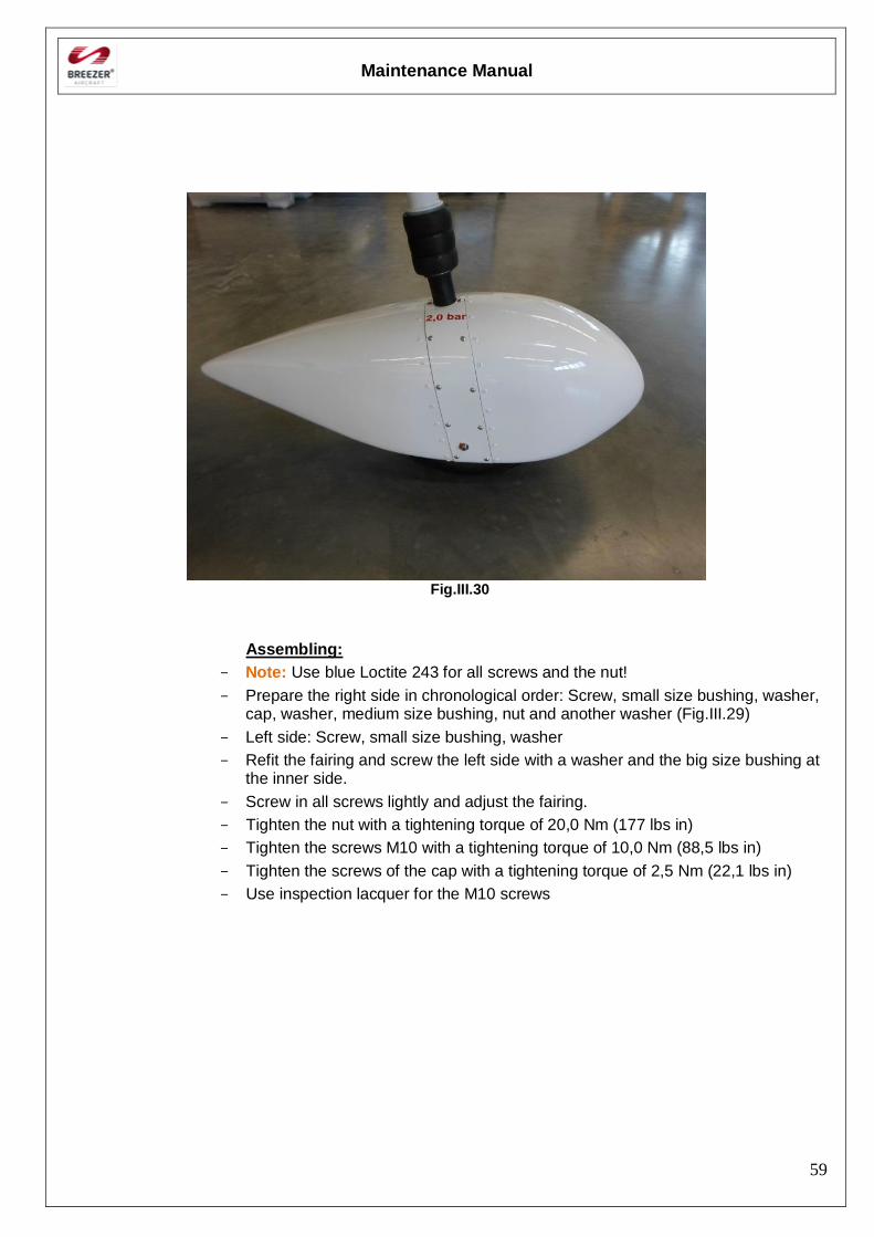
Fig.III.30
Assembling:
- Note: Use blue Loctite 243 for all screws and the nut!
- Prepare the right side in chronological order: Screw, small size bushing, washer, cap, washer, medium size bushing, nut and another washer (Fig.III.29)
- Left side: Screw, small size bushing, washer
- Refit the fairing and screw the left side with a washer and the big size bushing at the inner side.
- Screw in all screws lightly and adjust the fairing.
- Tighten the nut with a tightening torque of 20,0 Nm (177 lbs in)
- Tighten the screws M10 with a tightening torque of 10,0 Nm (88,5 lbs in)
- Tighten the screws of the cap with a tightening torque of 2,5 Nm (22,1 lbs in)
- Use inspection lacquer for the M10 screws
Maintenance Manual
60
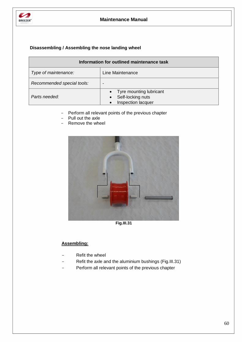
Disassembling / Assembling the nose landing wheel
Information for outlined maintenance task
Type of maintenance: Line Maintenance
Recommended special tools: -
Parts needed: Tyre mounting lubricant
Self-locking nuts
Inspection lacquer
- Perform all relevant points of the previous chapter - Pull out the axle - Remove the wheel
Fig.III.31
Assembling:
- Refit the wheel
- Refit the axle and the aluminium bushings (Fig.III.31)
- Perform all relevant points of the previous chapter
Maintenance Manual
61
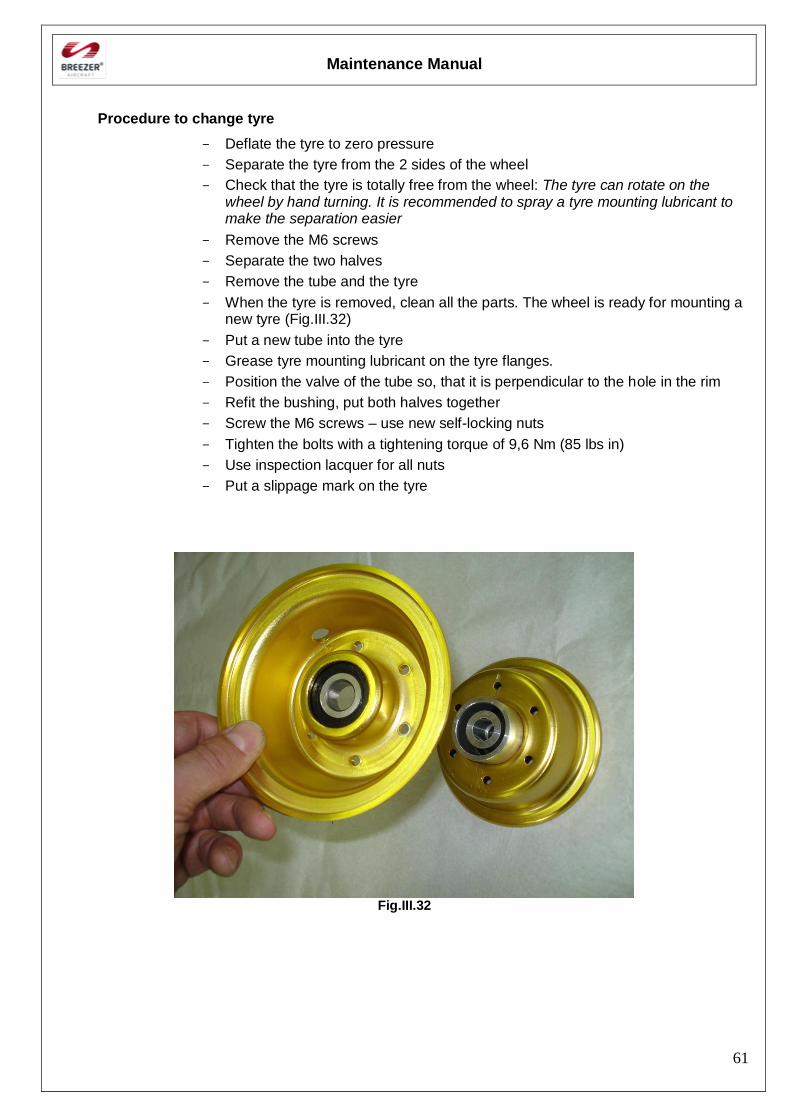
Procedure to change tyre
- Deflate the tyre to zero pressure
- Separate the tyre from the 2 sides of the wheel
- Check that the tyre is totally free from the wheel: The tyre can rotate on the wheel by hand turning. It is recommended to spray a tyre mounting lubricant to make the separation easier
- Remove the M6 screws
- Separate the two halves
- Remove the tube and the tyre
- When the tyre is removed, clean all the parts. The wheel is ready for mounting a new tyre (Fig.III.32)
- Put a new tube into the tyre
- Grease tyre mounting lubricant on the tyre flanges.
- Position the valve of the tube so, that it is perpendicular to the hole in the rim
- Refit the bushing, put both halves together
- Screw the M6 screws – use new self-locking nuts
- Tighten the bolts with a tightening torque of 9,6 Nm (85 lbs in)
- Use inspection lacquer for all nuts
- Put a slippage mark on the tyre
Fig.III.32
Maintenance Manual
62
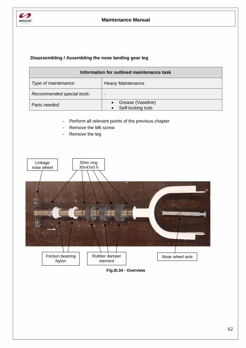
Disassembling / Assembling the nose landing gear leg
Information for outlined maintenance task
Type of maintenance: Heavy Maintenance
Recommended special tools: -
Parts needed: Grease (Vaseline)
Self-locking nuts
- Perform all relevant points of the previous chapter
- Remove the M6 screw
- Remove the leg
Fig.III.34 - Overview
Linkage nose wheel
Friction bearimg Nylon
Shim ring 30x42x0,5
Rubber damper element
Nose wheel axle
Maintenance Manual
63
Assembling:
- Grease copiously all rubber damper, shim rings and the leg with vaseline
- Check if all shim rings and rubber damper are positioned as shown in Fig.III.34
- Grease copiously the friction bearing and leg with vaseline
- Refit the axle and the aluminium bushings (Fig.III.31)
- Refit the linkage nose wheel
- Screw the M6 screws – use new self-locking nuts
- Tighten the bolts with a tightening torque of 10 Nm (88,5 lbs in)
- Perform all relevant points of the previous chapter
Maintenance Manual
64
Brake system
General
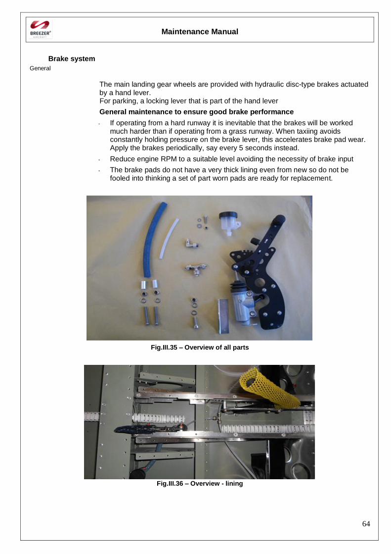
The main landing gear wheels are provided with hydraulic disc-type brakes actuated by a hand lever. For parking, a locking lever that is part of the hand lever
General maintenance to ensure good brake performance
- If operating from a hard runway it is inevitable that the brakes will be worked much harder than if operating from a grass runway. When taxiing avoids constantly holding pressure on the brake lever, this accelerates brake pad wear. Apply the brakes periodically, say every 5 seconds instead.
- Reduce engine RPM to a suitable level avoiding the necessity of brake input
- The brake pads do not have a very thick lining even from new so do not be fooled into thinking a set of part worn pads are ready for replacement.
Fig.III.35 – Overview of all parts
Fig.III.36 – Overview - lining
Maintenance Manual
65
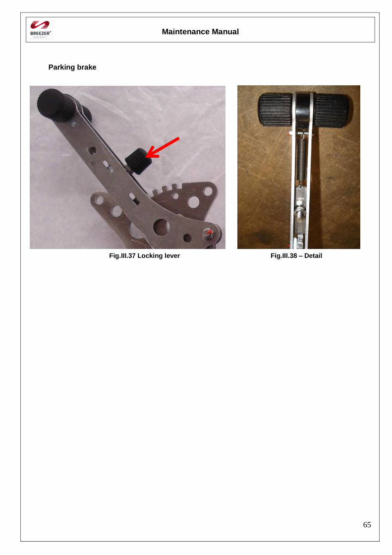
Parking brake
Fig.III.37 Locking lever Fig.III.38 – Detail
Maintenance Manual
66
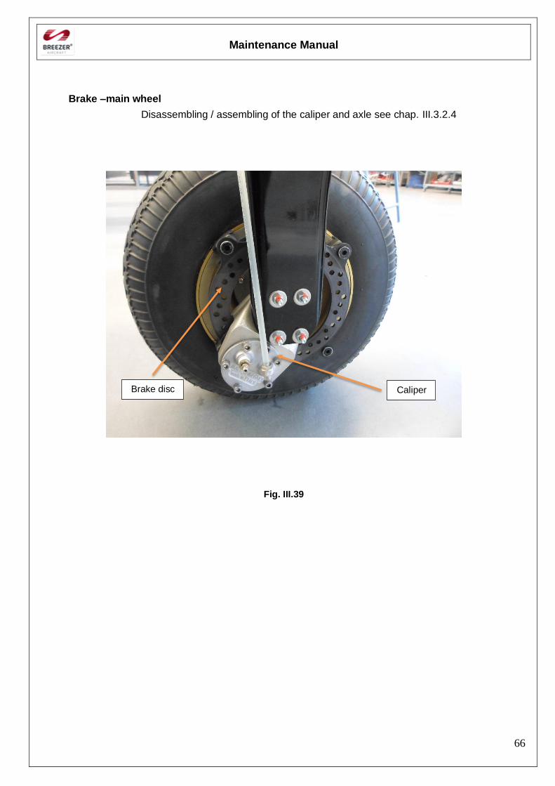
Brake –main wheel
Disassembling / assembling of the caliper and axle see chap. III.3.2.4
Fig. III.39
Brake disc Caliper
Maintenance Manual
67
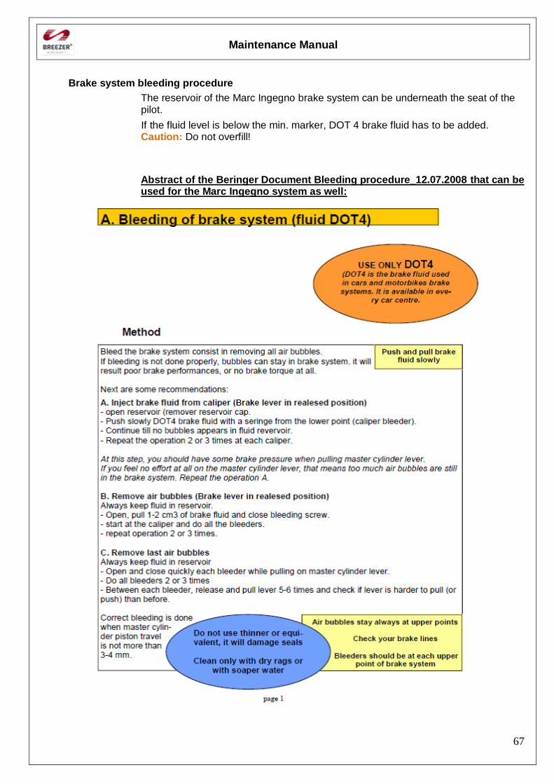
Brake system bleeding procedure
The reservoir of the Marc Ingegno brake system can be underneath the seat of the pilot.
If the fluid level is below the min. marker, DOT 4 brake fluid has to be added. Caution: Do not overfill!
Abstract of the Beringer Document Bleeding procedure_12.07.2008 that can be used for the Marc Ingegno system as well:
Maintenance Manual
68
Maintenance Manual
69
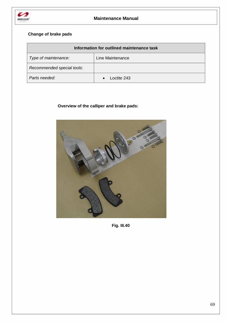
Change of brake pads
Information for outlined maintenance task
Type of maintenance: Line Maintenance
Recommended special tools:
Parts needed: Loctite 243
Overview of the calliper and brake pads:
Fig. III.40
Maintenance Manual
70
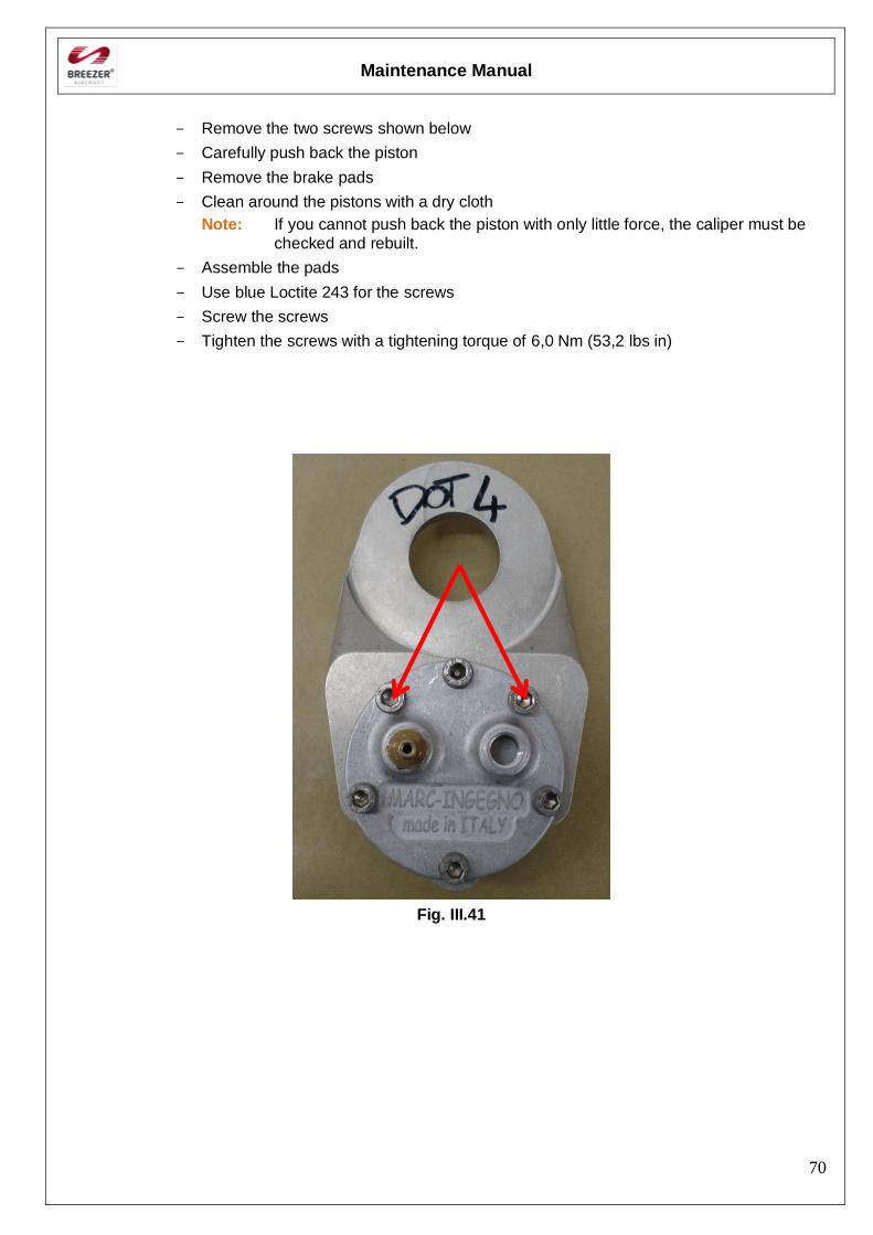
- Remove the two screws shown below
- Carefully push back the piston
- Remove the brake pads
- Clean around the pistons with a dry cloth
Note: If you cannot push back the piston with only little force, the caliper must be
checked and rebuilt.
- Assemble the pads
- Use blue Loctite 243 for the screws
- Screw the screws
- Tighten the screws with a tightening torque of 6,0 Nm (53,2 lbs in)
Fig. III.41

Maintenance Manual
71
[Intentionally left blank]
Maintenance Manual
72
18. Flight controls and control surfaces
General
The Breezer is equipped with dual controls which enables pilot training. Flight controls include:
- Ailerons (Lateral control)
- Wing flap control
- Elevators (Longitudinal control)
- Rudder (Directional control)
- Elevator trim tab control
- Aileron trim tab control
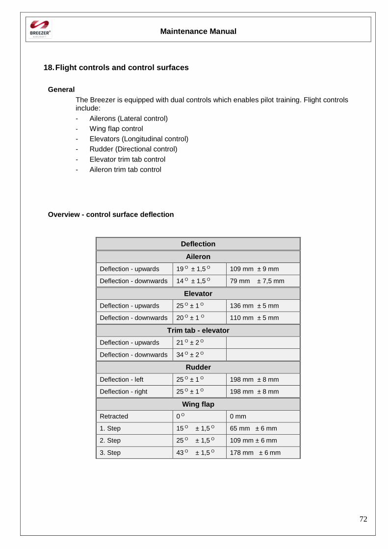
Overview - control surface deflection
Deflection
Aileron
Deflection - upwards 19 O ± 1,5 O 109 mm ± 9 mm
Deflection - downwards 14 O ± 1,5 O 79 mm ± 7,5 mm
Elevator
Deflection - upwards 25 O ± 1 O 136 mm ± 5 mm
Deflection - downwards 20 O ± 1 O 110 mm ± 5 mm
Trim tab - elevator
Deflection - upwards 21 O ± 2 O
Deflection - downwards 34 O ± 2 O
Rudder
Deflection - left 25 O ± 1 O 198 mm ± 8 mm
Deflection - right 25 O ± 1 O 198 mm ± 8 mm
Wing flap
Retracted 0 O 0 mm
1. Step 15 O ± 1,5 O 65 mm ± 6 mm
2. Step 25 O ± 1,5 O 109 mm ± 6 mm
3. Step 43 O ± 1,5 O 178 mm ± 6 mm
Maintenance Manual
73
Disassembling / Assembling of the flight controls
Information for outlined maintenance task
Type of maintenance: Heavy Maintenance
Recommended special tools: -
Parts needed: Acid-free grease
Self-locking nuts
Inspection lacquer
General
Orientation of bolts
Unless otherwise stated, the orientation of the bolts follows following rules: - “Top-down” - “From the front to the back" with regard to the flight direction. - “From inside to outside” These rules decreases possibility of spontaneous bolt falling out of the clamp joint in case that nut unlocking and falling out occurs during operation. Lubrication - general
At assembling parts grease all joints and friction surfaces (bolts, pins, threads) after mechanical or chemical cleaning by lubricant grease. The attachment of Elevator, Aileron and Rudder is made by hinges that are fixed with bolts (5 mm diam.) Disassembling:
- Screw off the control rod/cable
- Screw off the bolts of the hinges Be very careful and pay Caution to the friction bearing!
Maintenance Manual
74
Assembling:
- If necessary, use grease for the bolt and friction bearing
- Screw on the bolts of the hinges
- Tighten the bolt with a tightening torque of 1,5 – 2,0 Nm (13,3-17,7 lbs in) Note: - Do not compress the friction bearing! - Do not use the lock nut for more than 2 times!
- Screw on the control rod / cable
- Tighten the bolt with a tightening torque of 9,0 Nm (79,6 lbs in) Note: Do not use the lock nut for more than 2 times! - Use inspection lacquer for all nuts Note:
Acid-free grease should be used. In order to prevent unnecessary dirtying of the aircraft, do not use too much grease. Before flying, check the function and smooth running of the flight controls carefully
Maintenance Manual
75
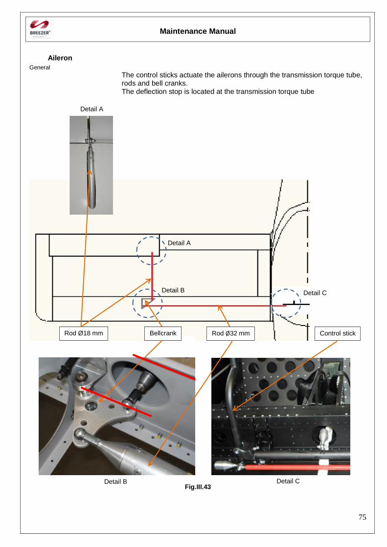
Aileron
General
The control sticks actuate the ailerons through the transmission torque tube, rods and bell cranks. The deflection stop is located at the transmission torque tube
Fig.III.43
Rod Ø18 mm Bellcrank Rod Ø32 mm Control stick
Detail A
Detail B Detail C
Detail A
Detail B Detail C
Maintenance Manual
76
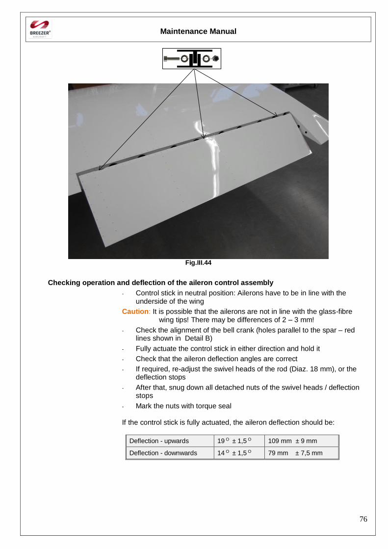
Fig.III.44
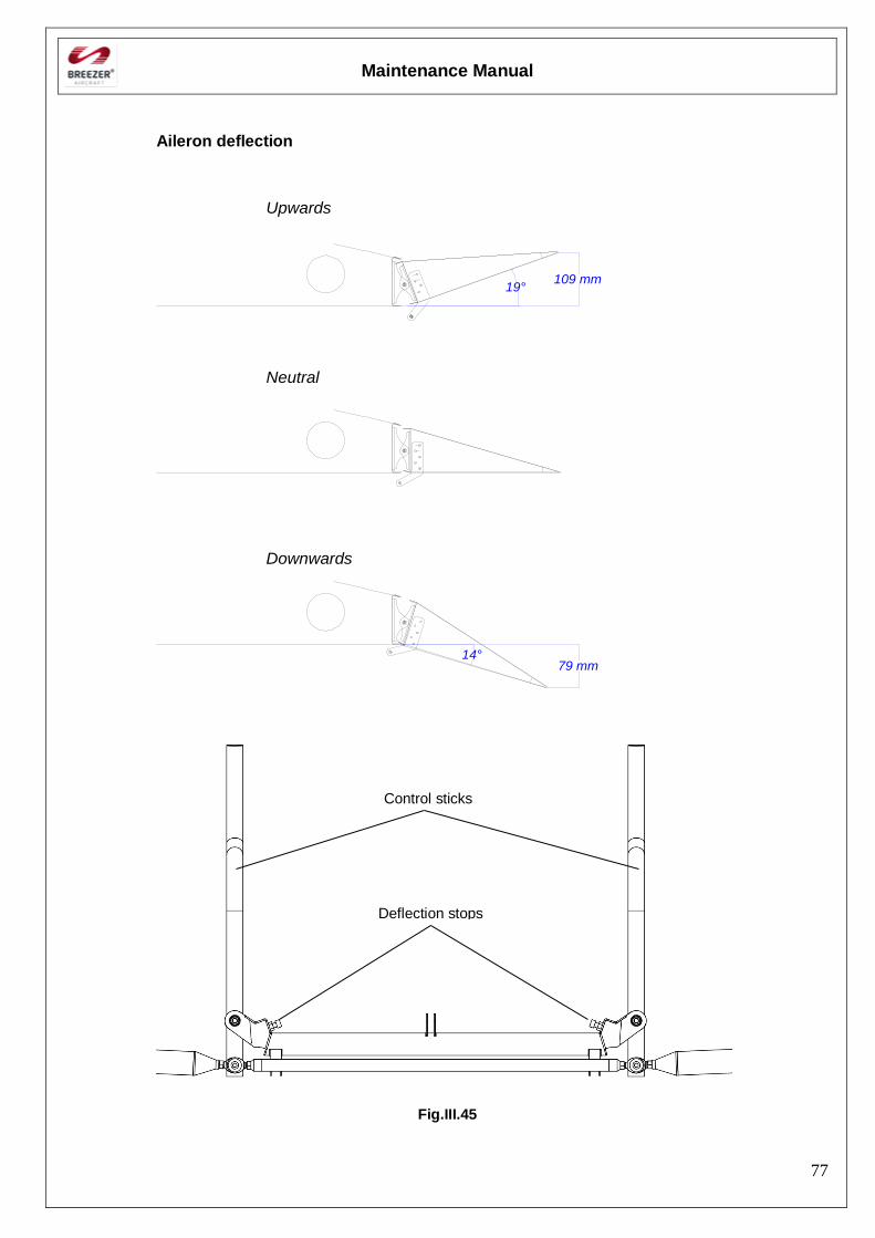
Checking operation and deflection of the aileron control assembly
- Control stick in neutral position: Ailerons have to be in line with the underside of the wing
Caution: It is possible that the ailerons are not in line with the glass-fibre wing tips! There may be differences of 2 – 3 mm!
- Check the alignment of the bell crank (holes parallel to the spar – red lines shown in Detail B)
- Fully actuate the control stick in either direction and hold it
- Check that the aileron deflection angles are correct
- If required, re-adjust the swivel heads of the rod (Diaz. 18 mm), or the deflection stops
- After that, snug down all detached nuts of the swivel heads / deflection stops
- Mark the nuts with torque seal
If the control stick is fully actuated, the aileron deflection should be:
Deflection - upwards 19 O ± 1,5 O 109 mm ± 9 mm
Deflection - downwards 14 O ± 1,5 O 79 mm ± 7,5 mm
Maintenance Manual
77
Aileron deflection
14°79 mm
19°109 mm
Upwards
Neutral
Downwards
Fig.III.45
Deflection stops
Control sticks
Maintenance Manual
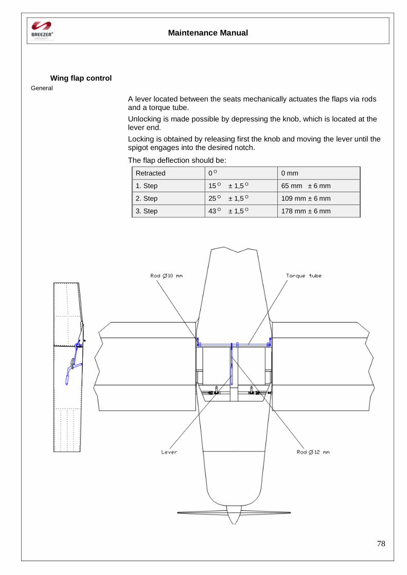
78
Wing flap control
General
A lever located between the seats mechanically actuates the flaps via rods and a torque tube.
Unlocking is made possible by depressing the knob, which is located at the lever end.
Locking is obtained by releasing first the knob and moving the lever until the spigot engages into the desired notch.
The flap deflection should be:
Retracted 0 O 0 mm
1. Step 15 O ± 1,5 O 65 mm ± 6 mm
2. Step 25 O ± 1,5 O 109 mm ± 6 mm
3. Step 43 O ± 1,5 O 178 mm ± 6 mm
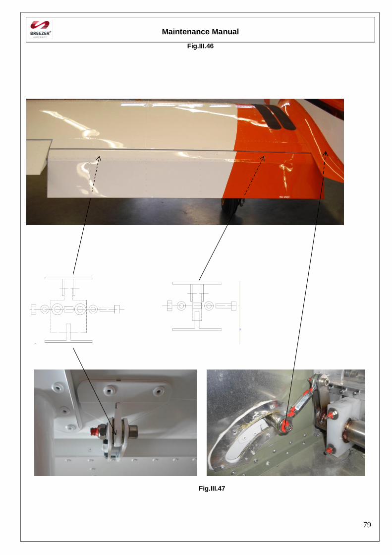
Maintenance Manual
79
Fig.III.46
Fig.III.47
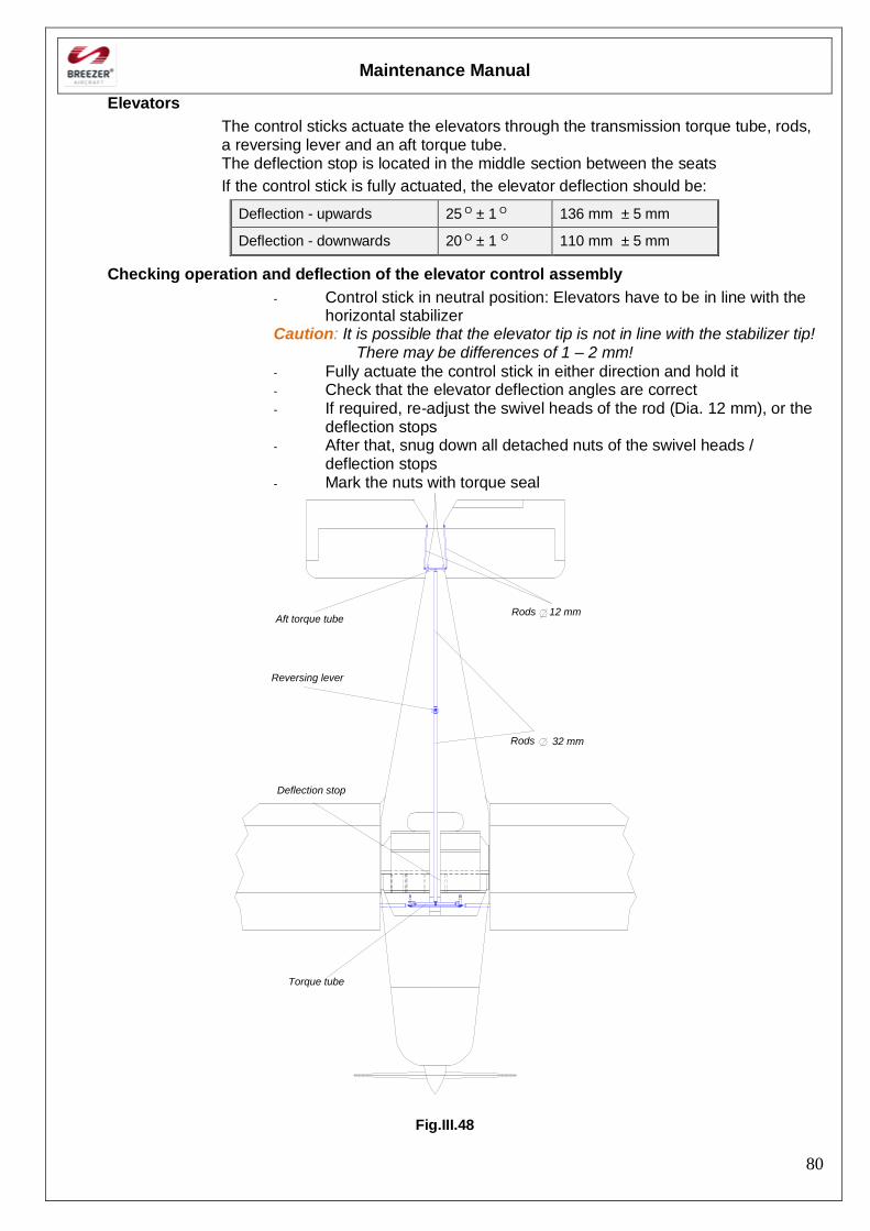
Maintenance Manual
80
Elevators
The control sticks actuate the elevators through the transmission torque tube, rods, a reversing lever and an aft torque tube. The deflection stop is located in the middle section between the seats
If the control stick is fully actuated, the elevator deflection should be:
Deflection - upwards 25 O ± 1 O 136 mm ± 5 mm
Deflection - downwards 20 O ± 1 O 110 mm ± 5 mm
Checking operation and deflection of the elevator control assembly
- Control stick in neutral position: Elevators have to be in line with the horizontal stabilizer
Caution: It is possible that the elevator tip is not in line with the stabilizer tip! There may be differences of 1 – 2 mm!
- Fully actuate the control stick in either direction and hold it - Check that the elevator deflection angles are correct - If required, re-adjust the swivel heads of the rod (Dia. 12 mm), or the
deflection stops - After that, snug down all detached nuts of the swivel heads /
deflection stops - Mark the nuts with torque seal
Torque tube
Deflection stop
Rods
Aft torque tube
Reversing lever
Rods 12 mm
32 mm
Fig.III.48
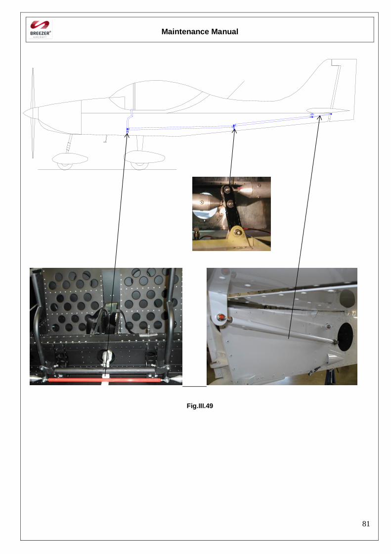
Maintenance Manual
81
Fig.III.49
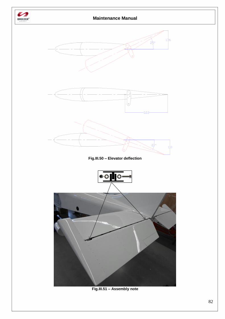
Maintenance Manual
82
Fig.III.50 – Elevator deflection
Fig.III.51 – Assembly note
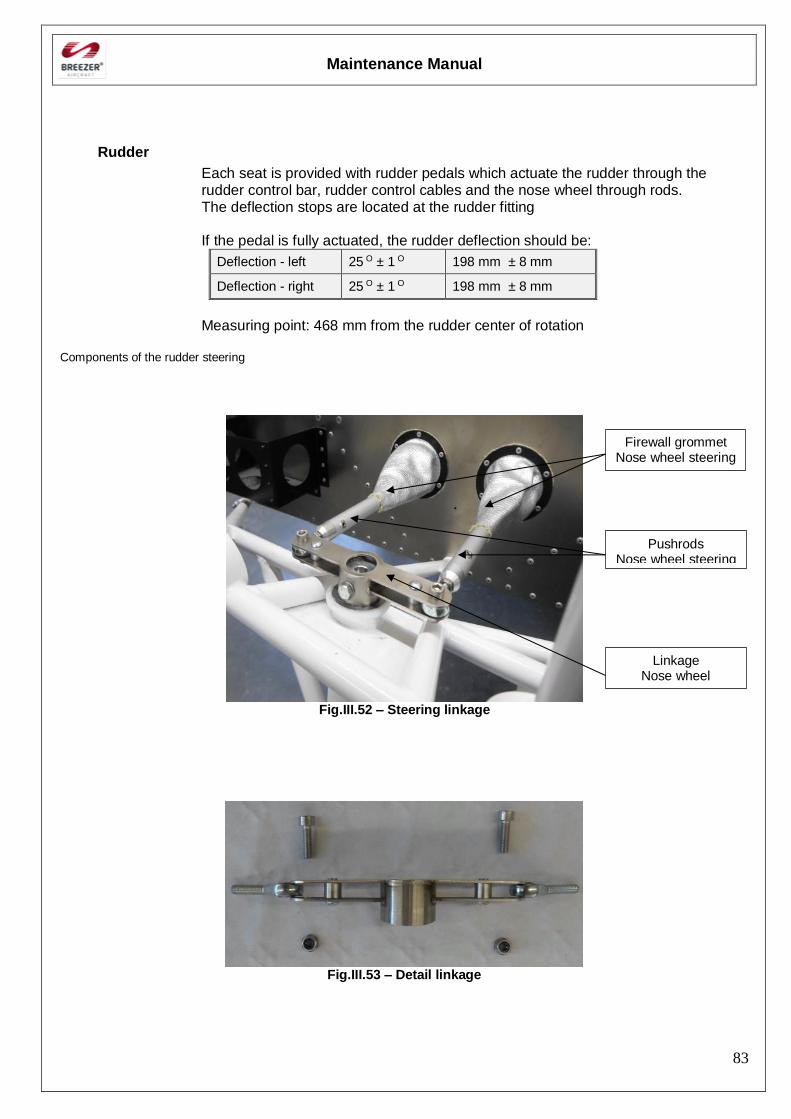
Maintenance Manual
83
Rudder
Each seat is provided with rudder pedals which actuate the rudder through the rudder control bar, rudder control cables and the nose wheel through rods. The deflection stops are located at the rudder fitting If the pedal is fully actuated, the rudder deflection should be:
Deflection - left 25 O ± 1 O 198 mm ± 8 mm
Deflection - right 25 O ± 1 O 198 mm ± 8 mm
Measuring point: 468 mm from the rudder center of rotation
Components of the rudder steering
Fig.III.52 – Steering linkage
Fig.III.53 – Detail linkage
Pushrods Nose wheel steering
Linkage Nose wheel
Firewall grommet Nose wheel steering
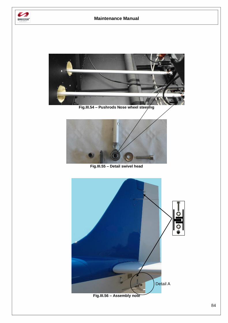
Maintenance Manual
84
Fig.III.54 – Pushrods Nose wheel steering
Fig.III.55 – Detail swivel head
Fig.III.56 – Assembly note
Detail A
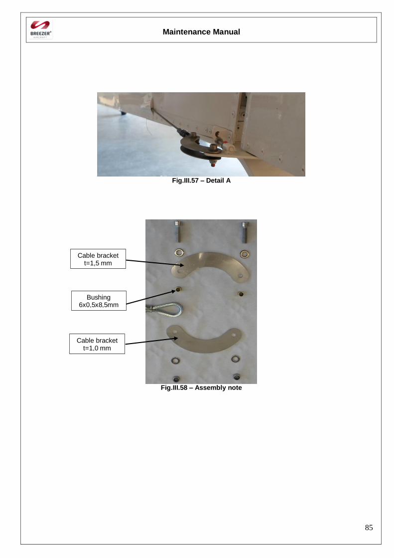
Maintenance Manual
85
Fig.III.57 – Detail A
Fig.III.58 – Assembly note
Cable bracket t=1,5 mm
Cable bracket t=1,0 mm
Bushing 6x0,5x8,5mm
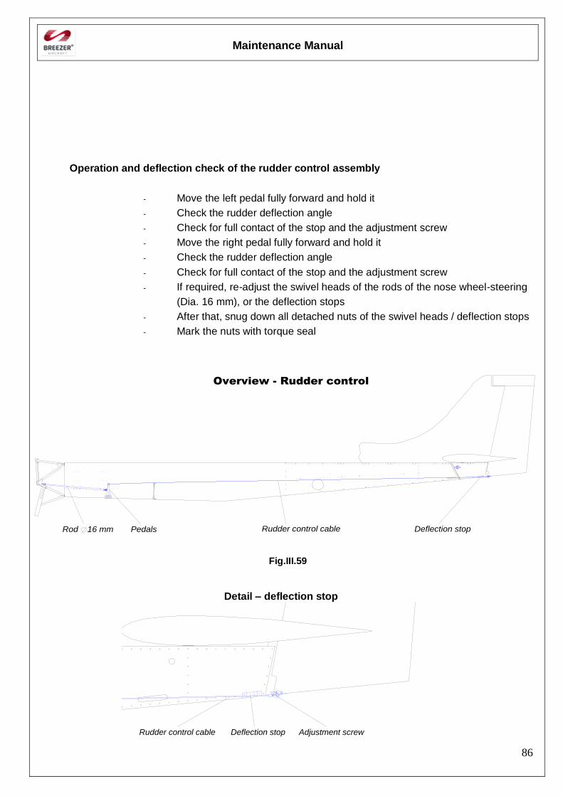
Maintenance Manual
86
Operation and deflection check of the rudder control assembly
- Move the left pedal fully forward and hold it
- Check the rudder deflection angle
- Check for full contact of the stop and the adjustment screw
- Move the right pedal fully forward and hold it
- Check the rudder deflection angle
- Check for full contact of the stop and the adjustment screw
- If required, re-adjust the swivel heads of the rods of the nose wheel-steering
(Dia. 16 mm), or the deflection stops
- After that, snug down all detached nuts of the swivel heads / deflection stops
- Mark the nuts with torque seal
16 mmRod Pedals Deflection stopRudder control cable
Overview - Rudder control
Fig.III.59
Detail – deflection stop
Adjustment screwRudder control cable Deflection stop
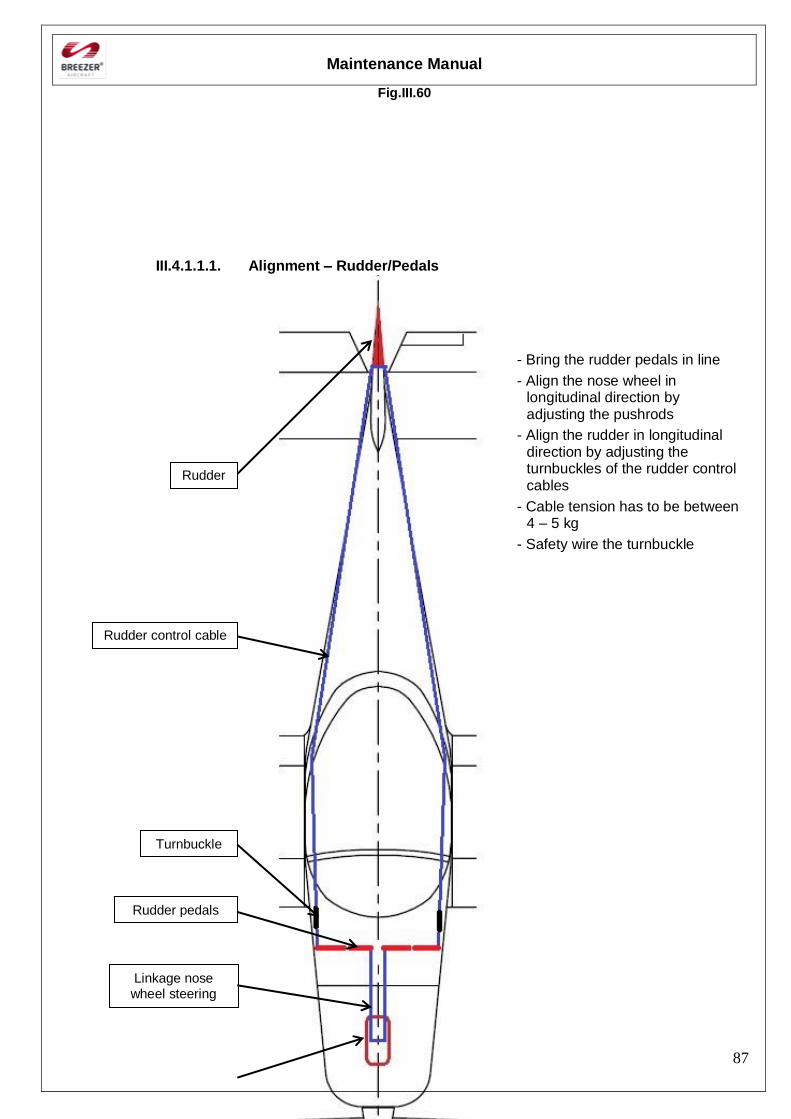
Maintenance Manual
87
Fig.III.60
III.4.1.1.1. Alignment – Rudder/Pedals
Rudder
Turnbuckle
Rudder pedals
Linkage nose wheel steering
Rudder control cable
- Bring the rudder pedals in line
- Align the nose wheel in longitudinal direction by adjusting the pushrods
- Align the rudder in longitudinal direction by adjusting the turnbuckles of the rudder control cables
- Cable tension has to be between 4 – 5 kg
- Safety wire the turnbuckle
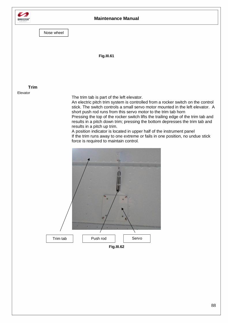
Maintenance Manual
88
Fig.III.61
Trim
Elevator
The trim tab is part of the left elevator. An electric pitch trim system is controlled from a rocker switch on the control stick. The switch controls a small servo motor mounted in the left elevator. A short push rod runs from this servo motor to the trim tab horn Pressing the top of the rocker switch lifts the trailing edge of the trim tab and results in a pitch down trim; pressing the bottom depresses the trim tab and results in a pitch up trim. A position indicator is located in upper half of the instrument panel If the trim runs away to one extreme or fails in one position, no undue stick force is required to maintain control.
Fig.III.62
Trim tab Push rod Servo
Nose wheel
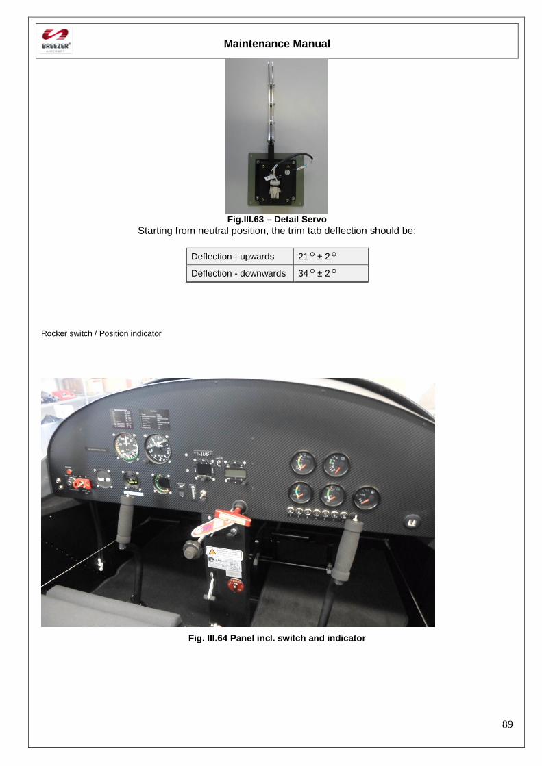
Maintenance Manual
89
Fig.III.63 – Detail Servo
Starting from neutral position, the trim tab deflection should be:
Deflection - upwards 21 O ± 2 O
Deflection - downwards 34 O ± 2 O
Rocker switch / Position indicator
Fig. III.64 Panel incl. switch and indicator
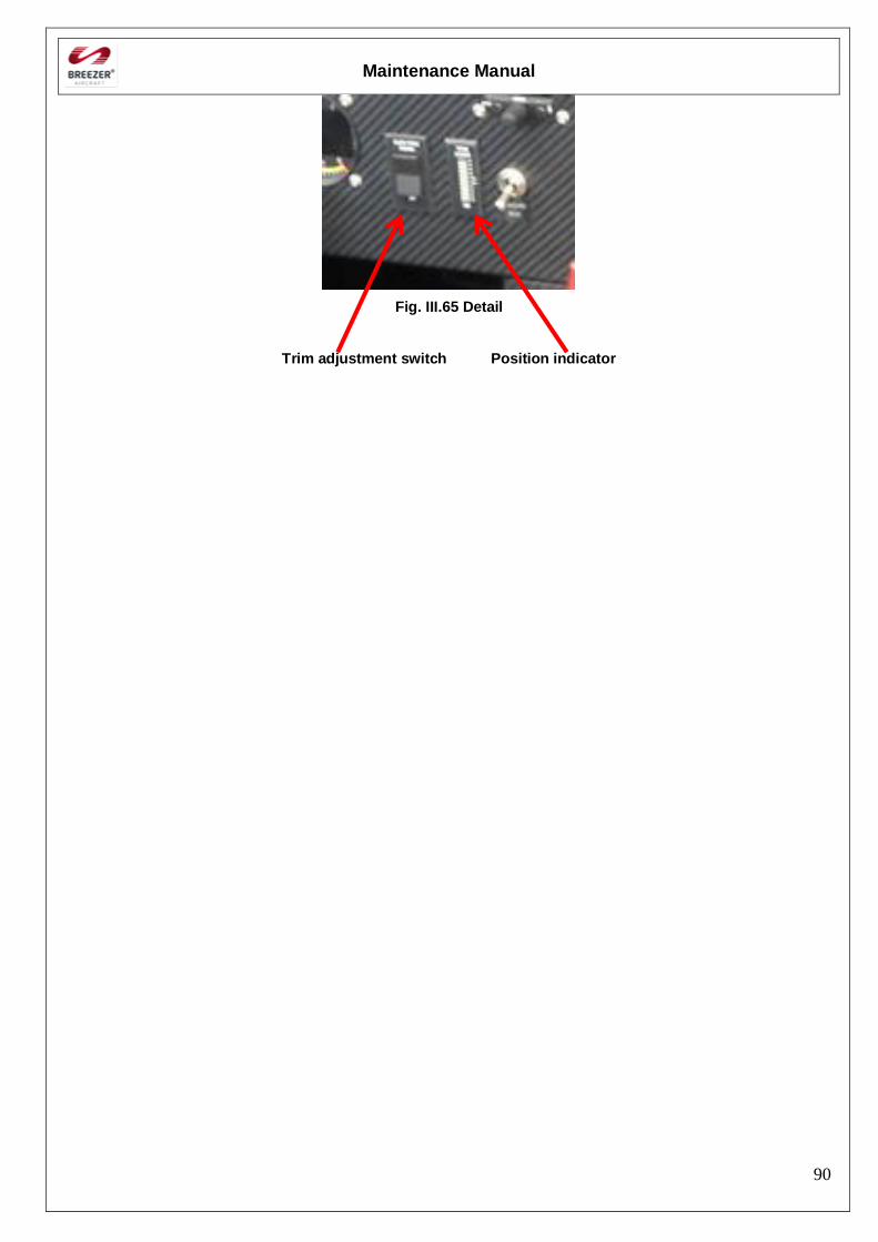
Maintenance Manual
90
Fig. III.65 Detail
Trim adjustment switch Position indicator

Maintenance Manual
91
[Intentionally left blank]
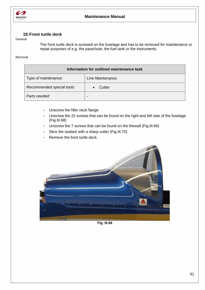
Maintenance Manual
92
19. Front turtle deck General
The front turtle deck is screwed on the fuselage and has to be removed for maintenance or repair purposes of e.g. the parachute, the fuel tank or the instruments.
Removal
Information for outlined maintenance task
Type of maintenance: Line Maintenance
Recommended special tools: Cutter
Parts needed: -
- Unscrew the filler neck flange
- Unscrew the 22 screws that can be found on the right and left side of the fuselage (Fig.III.68)
- Unscrew the 7 screws that can be found on the firewall (Fig.III.69)
- Slice the sealant with a sharp cutter (Fig.III.70)
- Remove the front turtle deck
Fig. III.68
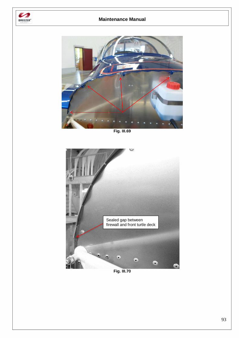
Maintenance Manual
93
Fig. III.69
Fig. III.70
Sealed gap between firewall and front turtle deck
Maintenance Manual
94
Installation
Information for outlined maintenance task
Type of maintenance: Line Maintenance
Recommended special tools: -
Parts needed: Fire Barrier Silicone Sealant 2000+ (3M
Corporate)
- Remove leftover fragments of the sealer
- Position the front turtle deck
- Screw the 7 screws that can be found on the firewall (Fig.III.69)
- Screw the 22 screws that can be found on the right and left side of the fuselage (Fig.III.68)
- Screw the filler neck flange
- Seal the gap with fire resistant sealer
Note: Only Fire Barrier Silicone Sealant 2000+ (3M Corporate) is allowed to be used!
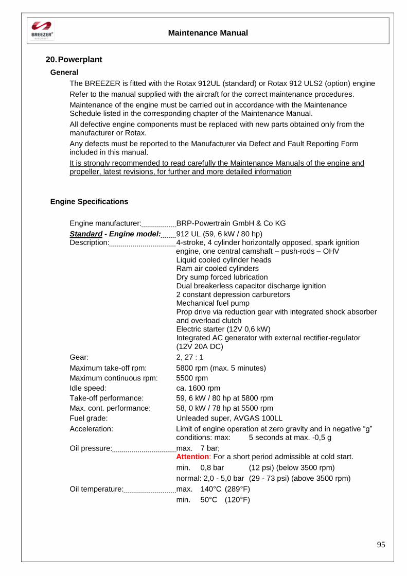
Maintenance Manual
95
20. Powerplant
General
The BREEZER is fitted with the Rotax 912UL (standard) or Rotax 912 ULS2 (option) engine
Refer to the manual supplied with the aircraft for the correct maintenance procedures.
Maintenance of the engine must be carried out in accordance with the Maintenance Schedule listed in the corresponding chapter of the Maintenance Manual.
All defective engine components must be replaced with new parts obtained only from the manufacturer or Rotax.
Any defects must be reported to the Manufacturer via Defect and Fault Reporting Form included in this manual.
It is strongly recommended to read carefully the Maintenance Manuals of the engine and propeller, latest revisions, for further and more detailed information
Engine Specifications
Engine manufacturer: BRP-Powertrain GmbH & Co KG
Standard - Engine model: 912 UL (59, 6 kW / 80 hp) Description: 4-stroke, 4 cylinder horizontally opposed, spark ignition
engine, one central camshaft – push-rods – OHV Liquid cooled cylinder heads Ram air cooled cylinders Dry sump forced lubrication Dual breakerless capacitor discharge ignition 2 constant depression carburetors Mechanical fuel pump
Prop drive via reduction gear with integrated shock absorber and overload clutch
Electric starter (12V 0,6 kW) Integrated AC generator with external rectifier-regulator
(12V 20A DC)
Gear: 2, 27 : 1
Maximum take-off rpm: 5800 rpm (max. 5 minutes)
Maximum continuous rpm: 5500 rpm
Idle speed: ca. 1600 rpm
Take-off performance: 59, 6 kW / 80 hp at 5800 rpm
Max. cont. performance: 58, 0 kW / 78 hp at 5500 rpm
Fuel grade: Unleaded super, AVGAS 100LL
Acceleration: Limit of engine operation at zero gravity and in negative “g” conditions: max: 5 seconds at max. -0,5 g
Oil pressure: max. 7 bar; Attention: For a short period admissible at cold start.
min. 0,8 bar (12 psi) (below 3500 rpm)
normal: 2,0 - 5,0 bar (29 - 73 psi) (above 3500 rpm)
Oil temperature: max. 140°C (289°F)
min. 50°C (120°F)
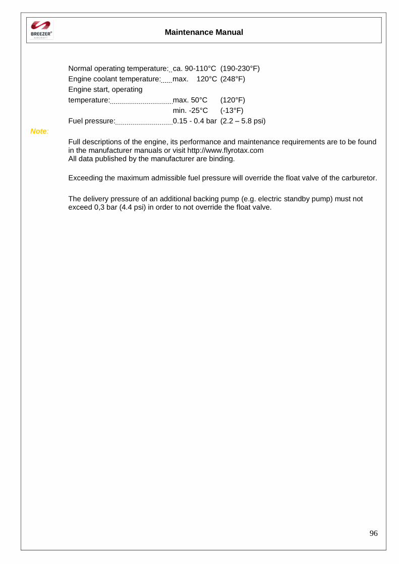
Maintenance Manual
96
Normal operating temperature: ca. 90-110°C (190-230°F)
Engine coolant temperature: max. 120°C (248°F)
Engine start, operating
temperature: max. 50°C (120°F)
min. -25°C (-13°F)
Fuel pressure: 0.15 - 0.4 bar (2.2 – 5.8 psi)
Note:
Full descriptions of the engine, its performance and maintenance requirements are to be found in the manufacturer manuals or visit http://www.flyrotax.com All data published by the manufacturer are binding.
Exceeding the maximum admissible fuel pressure will override the float valve of the carburetor.
The delivery pressure of an additional backing pump (e.g. electric standby pump) must not exceed 0,3 bar (4.4 psi) in order to not override the float valve.
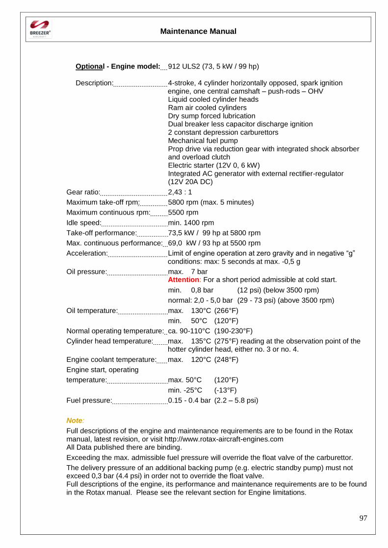
Maintenance Manual
97
Optional - Engine model: 912 ULS2 (73, 5 kW / 99 hp)
Description: 4-stroke, 4 cylinder horizontally opposed, spark ignition engine, one central camshaft – push-rods – OHV
Liquid cooled cylinder heads Ram air cooled cylinders Dry sump forced lubrication Dual breaker less capacitor discharge ignition 2 constant depression carburettors Mechanical fuel pump
Prop drive via reduction gear with integrated shock absorber and overload clutch
Electric starter (12V 0, 6 kW) Integrated AC generator with external rectifier-regulator (12V 20A DC)
Gear ratio: 2,43 : 1
Maximum take-off rpm: 5800 rpm (max. 5 minutes)
Maximum continuous rpm: 5500 rpm
Idle speed: min. 1400 rpm
Take-off performance: 73,5 kW / 99 hp at 5800 rpm
Max. continuous performance: 69,0 kW / 93 hp at 5500 rpm
Acceleration: Limit of engine operation at zero gravity and in negative “g” conditions: max: 5 seconds at max. -0,5 g
Oil pressure: max. 7 bar Attention: For a short period admissible at cold start.
min. 0,8 bar (12 psi) (below 3500 rpm)
normal: 2,0 - 5,0 bar (29 - 73 psi) (above 3500 rpm)
Oil temperature: max. 130°C (266°F)
min. 50°C (120°F)
Normal operating temperature: ca. 90-110°C (190-230°F)
Cylinder head temperature: max. 135°C (275°F) reading at the observation point of the hotter cylinder head, either no. 3 or no. 4.
Engine coolant temperature: max. 120°C (248°F)
Engine start, operating
temperature: max. 50°C (120°F)
min. -25°C (-13°F)
Fuel pressure: 0.15 - 0.4 bar (2.2 – 5.8 psi)
Note:
Full descriptions of the engine and maintenance requirements are to be found in the Rotax manual, latest revision, or visit http://www.rotax-aircraft-engines.com All Data published there are binding.
Exceeding the max. admissible fuel pressure will override the float valve of the carburettor.
The delivery pressure of an additional backing pump (e.g. electric standby pump) must not exceed 0,3 bar (4.4 psi) in order not to override the float valve. Full descriptions of the engine, its performance and maintenance requirements are to be found in the Rotax manual. Please see the relevant section for Engine limitations.
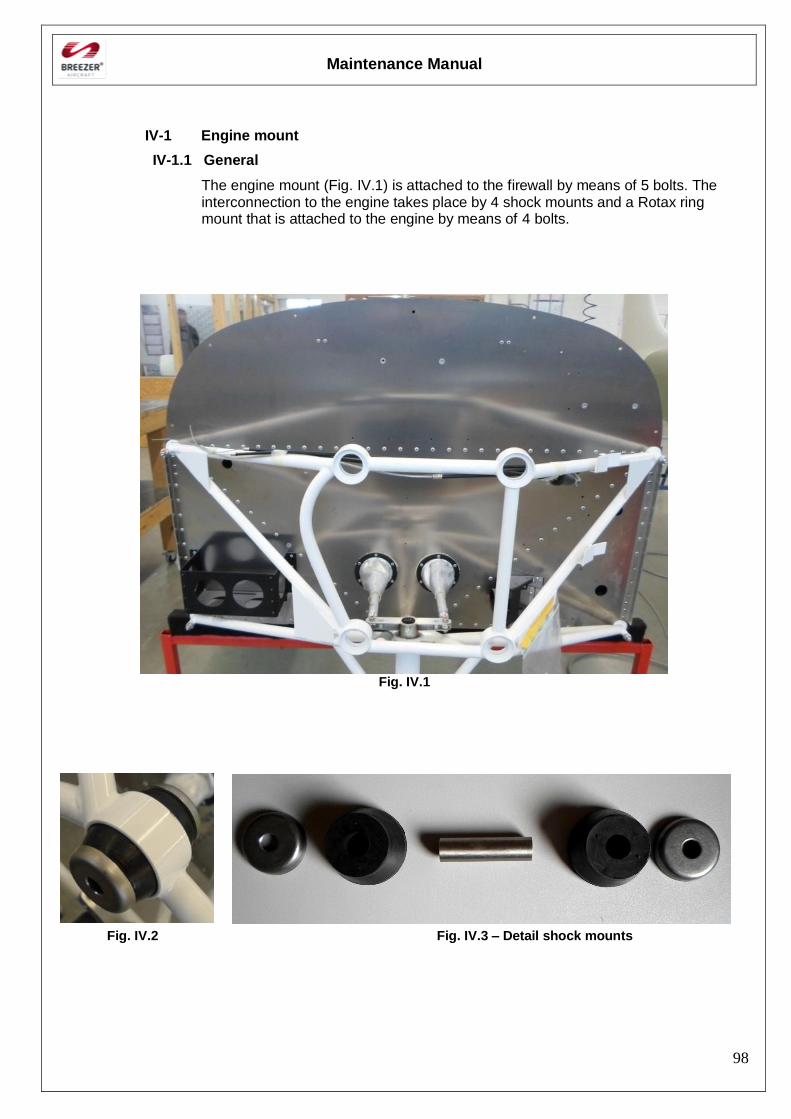
Maintenance Manual
98
IV-1 Engine mount
IV-1.1 General
The engine mount (Fig. IV.1) is attached to the firewall by means of 5 bolts. The interconnection to the engine takes place by 4 shock mounts and a Rotax ring mount that is attached to the engine by means of 4 bolts.
Fig. IV.1
Fig. IV.2 Fig. IV.3 – Detail shock mounts
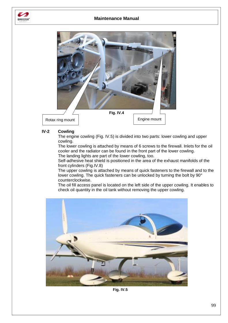
Maintenance Manual
99
Fig. IV.4
IV-2 Cowling
The engine cowling (Fig. IV.5) is divided into two parts: lower cowling and upper cowling. The lower cowling is attached by means of 6 screws to the firewall. Inlets for the oil cooler and the radiator can be found in the front part of the lower cowling. The landing lights are part of the lower cowling, too. Self-adhesive heat shield is positioned in the area of the exhaust manifolds of the front cylinders (Fig.IV.8) The upper cowling is attached by means of quick fasteners to the firewall and to the lower cowling. The quick fasteners can be unlocked by turning the bolt by 90° counterclockwise. The oil fill access panel is located on the left side of the upper cowling. It enables to check oil quantity in the oil tank without removing the upper cowling.
Fig. IV.5
Engine mount Rotax ring mount
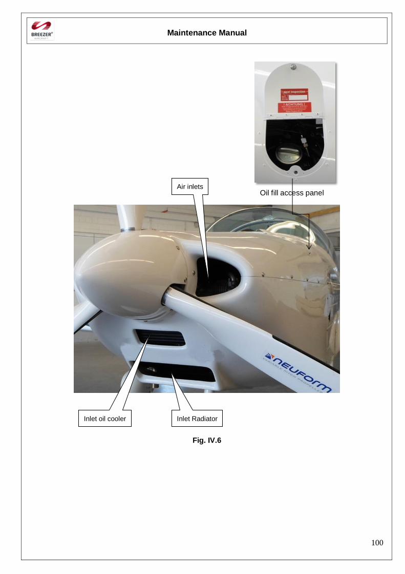
Maintenance Manual
100
Oil fill access panel
Fig. IV.6
Air inlets
Inlet oil cooler Inlet Radiator
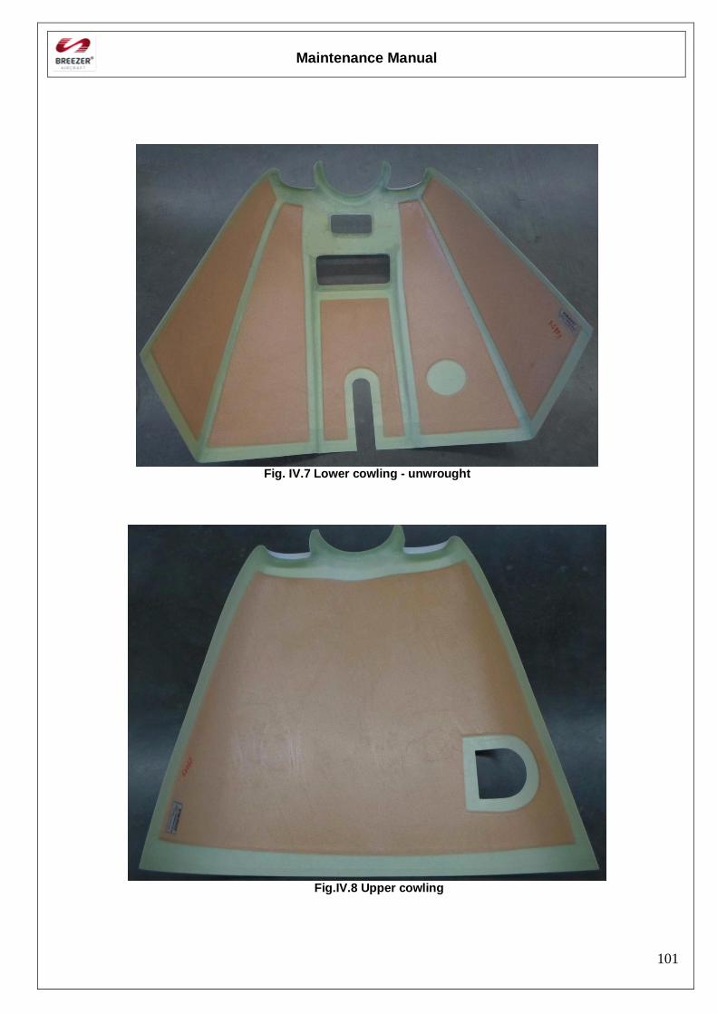
Maintenance Manual
101
Fig. IV.7 Lower cowling - unwrought
Fig.IV.8 Upper cowling
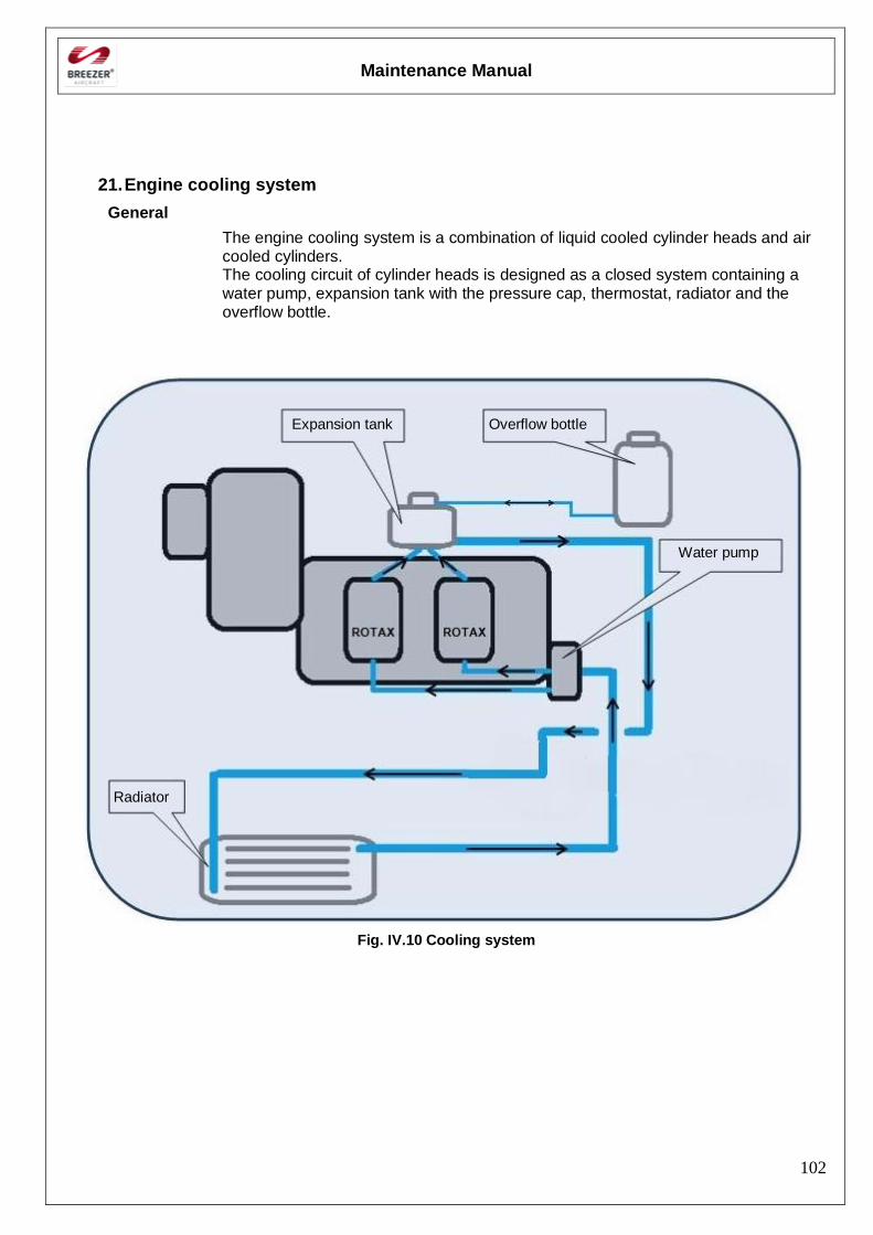
Maintenance Manual
102
21. Engine cooling system
General
The engine cooling system is a combination of liquid cooled cylinder heads and air cooled cylinders. The cooling circuit of cylinder heads is designed as a closed system containing a water pump, expansion tank with the pressure cap, thermostat, radiator and the overflow bottle.
Fig. IV.10 Cooling system
Expansion tank Overflow bottle
Water pump
Radiator
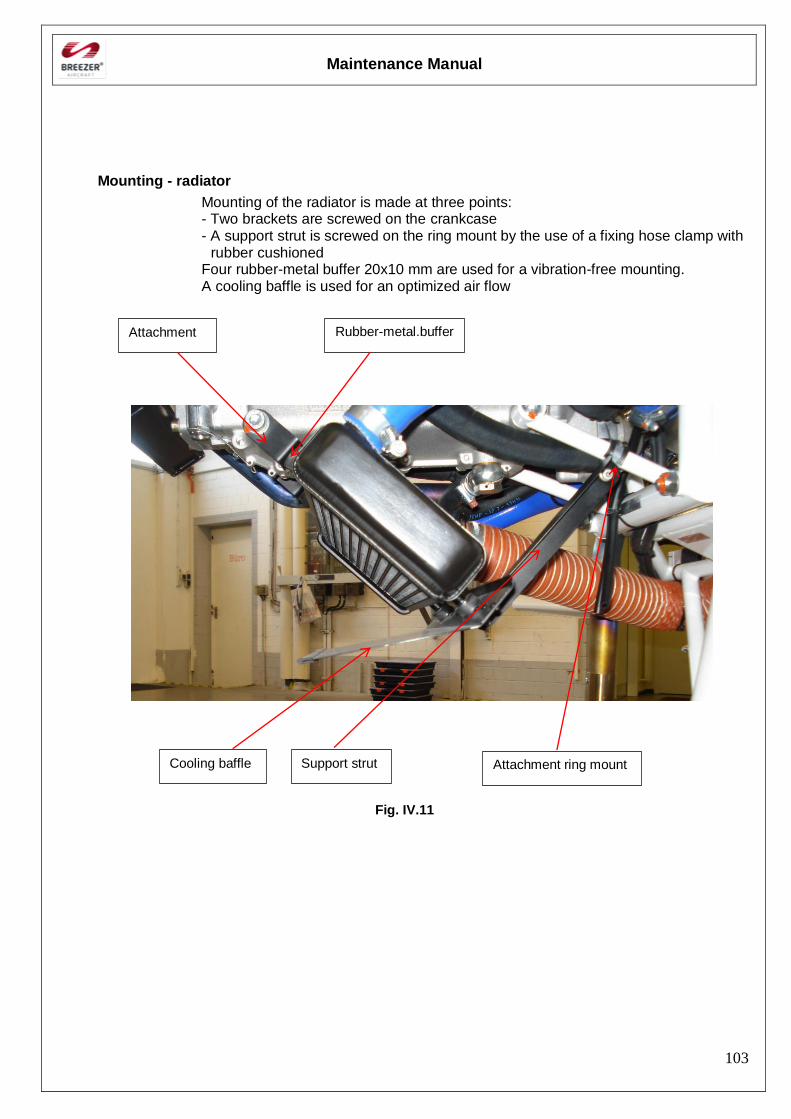
Maintenance Manual
103
Mounting - radiator
Mounting of the radiator is made at three points: - Two brackets are screwed on the crankcase - A support strut is screwed on the ring mount by the use of a fixing hose clamp with
rubber cushioned Four rubber-metal buffer 20x10 mm are used for a vibration-free mounting. A cooling baffle is used for an optimized air flow
Fig. IV.11
Attachment Rubber-metal.buffer
Cooling baffle Support strut Attachment ring mount
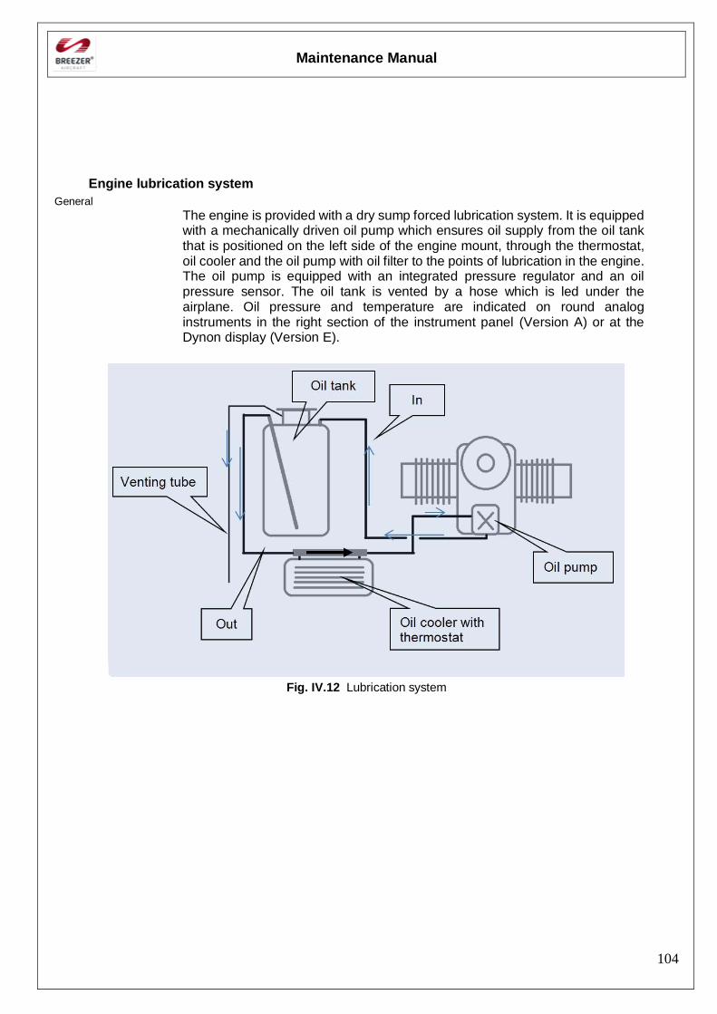
Maintenance Manual
104
Engine lubrication system
General
The engine is provided with a dry sump forced lubrication system. It is equipped with a mechanically driven oil pump which ensures oil supply from the oil tank that is positioned on the left side of the engine mount, through the thermostat, oil cooler and the oil pump with oil filter to the points of lubrication in the engine. The oil pump is equipped with an integrated pressure regulator and an oil pressure sensor. The oil tank is vented by a hose which is led under the airplane. Oil pressure and temperature are indicated on round analog instruments in the right section of the instrument panel (Version A) or at the Dynon display (Version E).
Fig. IV.12 Lubrication system
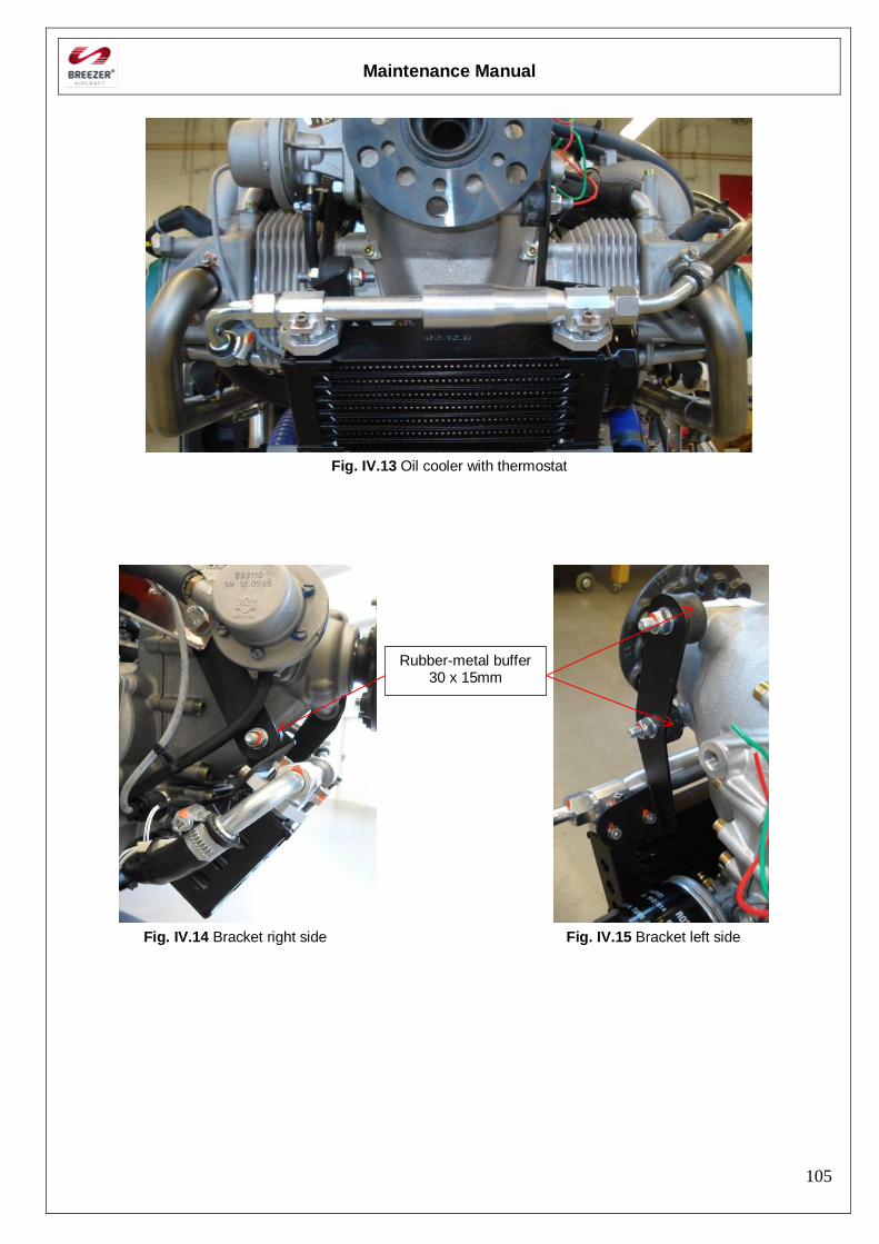
Maintenance Manual
105
Fig. IV.13 Oil cooler with thermostat
Fig. IV.14 Bracket right side Fig. IV.15 Bracket left side
Rubber-metal buffer 30 x 15mm
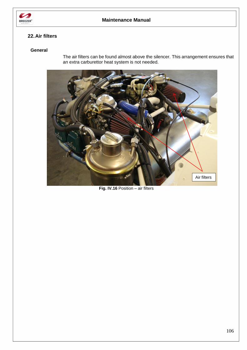
Maintenance Manual
106
22. Air filters
General
The air filters can be found almost above the silencer. This arrangement ensures that an extra carburettor heat system is not needed.
Fig. IV.16 Position – air filters
Air filters
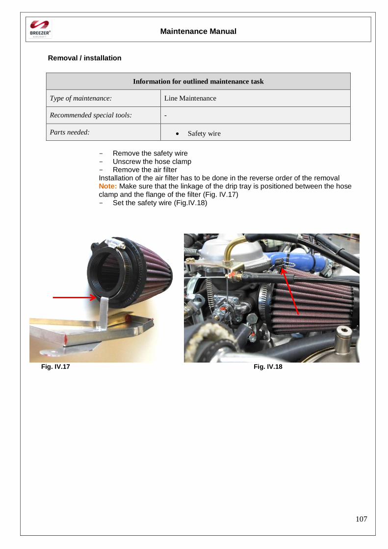
Maintenance Manual
107
Removal / installation
Information for outlined maintenance task
Type of maintenance: Line Maintenance
Recommended special tools: -
Parts needed: Safety wire
- Remove the safety wire - Unscrew the hose clamp - Remove the air filter Installation of the air filter has to be done in the reverse order of the removal Note: Make sure that the linkage of the drip tray is positioned between the hose clamp and the flange of the filter (Fig. IV.17) - Set the safety wire (Fig.IV.18)
Fig. IV.17 Fig. IV.18
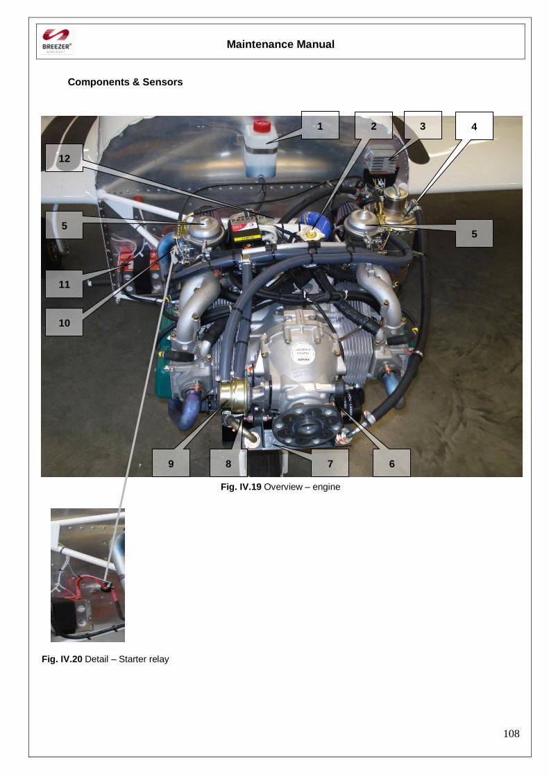
Maintenance Manual
108
Components & Sensors
Fig. IV.19 Overview – engine
Fig. IV.20 Detail – Starter relay
6
12
7
1
11
5
2 4
5
9 8
3
10
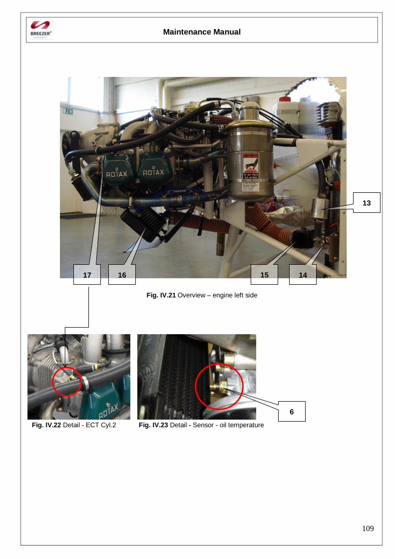
Maintenance Manual
109
Fig. IV.21 Overview – engine left side
Fig. IV.22 Detail - ECT Cyl.2 Fig. IV.23 Detail - Sensor - oil temperature
13
14
6
15 16 17
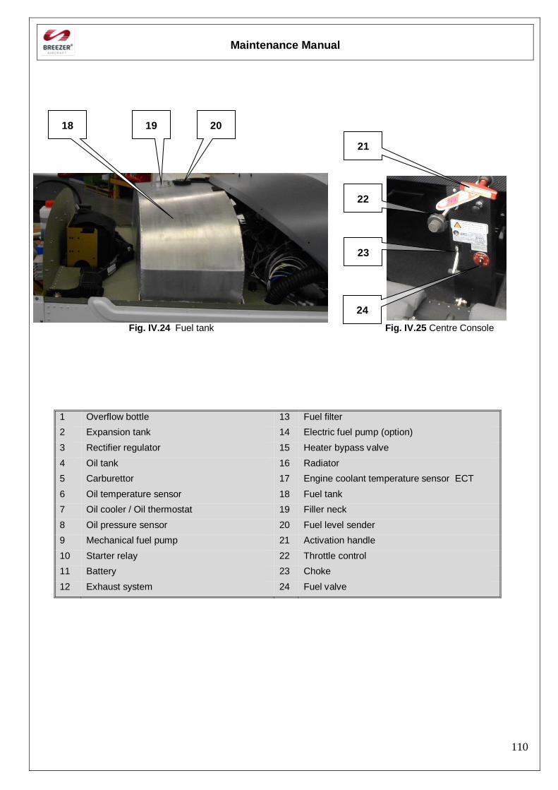
Maintenance Manual
110
Fig. IV.24 Fuel tank Fig. IV.25 Centre Console
1 Overflow bottle 13 Fuel filter
2 Expansion tank 14 Electric fuel pump (option)
3 Rectifier regulator 15 Heater bypass valve
4 Oil tank 16 Radiator
5 Carburettor 17 Engine coolant temperature sensor ECT
6 Oil temperature sensor 18 Fuel tank
7 Oil cooler / Oil thermostat 19 Filler neck
8 Oil pressure sensor 20 Fuel level sender
9 Mechanical fuel pump 21 Activation handle
10 Starter relay 22 Throttle control
11 Battery 23 Choke
12 Exhaust system 24 Fuel valve
18 20 19
22
23
24
21
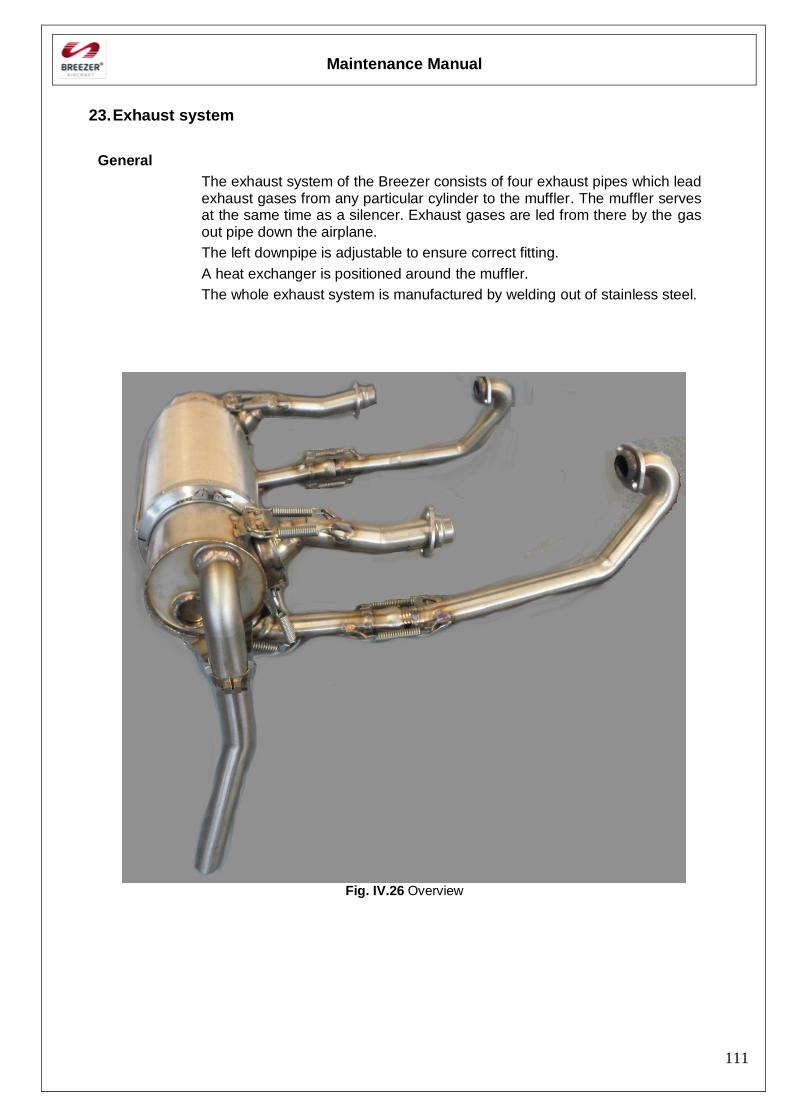
Maintenance Manual
111
23. Exhaust system
General
The exhaust system of the Breezer consists of four exhaust pipes which lead exhaust gases from any particular cylinder to the muffler. The muffler serves at the same time as a silencer. Exhaust gases are led from there by the gas out pipe down the airplane.
The left downpipe is adjustable to ensure correct fitting.
A heat exchanger is positioned around the muffler.
The whole exhaust system is manufactured by welding out of stainless steel.
Fig. IV.26 Overview
Maintenance Manual
112
24. Inspection, Removal and installation of engine components
Exhaust system
Information for outlined maintenance task
Type of maintenance: Line Maintenance
Recommended special tools: -
Parts needed:
Special lube (Breezer)
Safety wire
High heat silicone
IV-2.1.1 Inspection Warning: The exhaust system has to be checked very carefully!
A bursted or leaky exhaust can expose the crew to danger caused by carbon monoxide or can result in engine power loss or fire!
Check the exhaust system for cracks. Pay special attention to the following areas:
- Silencer in the area of the input and the output pipe and the collector head
- All welds and their immediate surrounding
- Carefully check all areas showing local overheating caused by exhaust gases
- Remove the heat exchanger and check the silencer area located under it
- Carefully check all exhaust pipes
- Check the gas out pipe of the silencer
- Check springs for damages/cracks.
IV-2.1.2 Removal WARNING: - Engine ignition must be switched off!
- Work must be carried out on a cold engine – Danger of burns!
- Remove engine cowling.
- Disconnect both air ducting from the heat exchanger
- Remove safety wire securing the springs
- Remove safety wire securing the slip joint
- Remove the springs from the individual exhaust pipes and carefully remove the silencer.
- Unscrew all nuts and remove the exhaust pipes from the exhaust ports.
Maintenance Manual
113
Installation
WARNING: Engine ignition must be switched off!
- Install the exhaust pipes - use the black lube to lubricate ball ends and cup joints.
Note: - Do not lubricate the clamped slip joint!
- Only the black lube delivered by Breezer Aviation should be used!
- Mind a proper arrangement, all pipes are numbered on the flange to identify their position on the engine – insert the pipe of the slip joint min. 20 mm (see Fig.IV.34)
- Screw the nuts on the bolts of the engine exhaust ports, do not tighten the nuts.
- Install the silencer and secure the pipes by means of the springs
- Ensure the clamped slip joint on the left exhaust pipe of cylinder 2 is loose
- Before tightening the flange nuts to 12 Nm, check that the silencer is in the correct position and that the downpipes of cylinders 1 and 2 appear laterally correct to each exhaust port.
- Gradually tighten all nuts of each exhaust port
Note: Ensure that there is sufficient space between the exhaust pipes/silencer and other installed parts.
- Finally tighten the M6 screw on the slip joint clamp
- Secure all springs with safety wire (see Fig.IV.35-38)
- For additional damping of vibrations, put high heat silicone on the springs (see Fig.IV.38)
- Secure the slip joint with a safety wire (see Fig.IV.34)
- Install the air ducting on the heat exchanger
- Install the engine cowling.
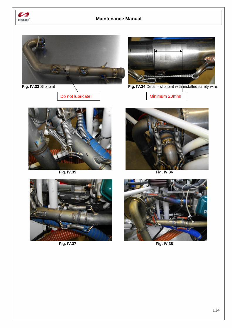
Maintenance Manual
114
Fig. IV.33 Slip joint Fig. IV.34 Detail - slip joint with installed safety wire
Fig. IV.35 Fig. IV.36
Fig. IV.37 Fig. IV.38
Do not lubricate! Minimum 20mm!
Maintenance Manual
115
Engine removal / installation
Information for outlined maintenance task
Type of maintenance: Heavy Maintenance
Recommended special tools: Crane for engine handling
Parts needed:
Inspection lacquer
Engine oil
Water cooling liquid
Self-locking nuts
Removal
- Remove the engine cowling.
- Shut the fuel valve
- Disconnect and remove the battery
- Remove the propeller
- Disconnect all electrical system wires and bonding between the engine mount and the firewall.
- Drain oil from the engine and cooling liquid
- Disconnect hoses of the oil and the cooling system.
- Remove the oil cooler and the radiator
- Disconnect control of carburetors
- Remove heating ducting
- Remove the exhaust system
- Blind all the holes on the engine so that no debris can get into the engine.
- Remove bolts and washers attaching the ring engine mount to the engine mount
- Take the engine away from the engine mount by a crane
- Store the removed engine on a safe place on a suitable support and prevent it from damage.
Caution: It is strongly recommended to read carefully the Rotax 912 ULS Maintenance Manual, latest revision, for further and more detailed information
Maintenance Manual
116
Installation
- Bring the engine into line with the engine ring mount with the help of a crane and attach it by the bolts with washers.
Orientation:
In flight direction (see also Fig. IV.4)
Note: Always use new self-locking nuts
- Tighten up to a torque of 40 Nm (354 in lbf).
- Use inspection lacquer for all nuts
- Install the exhaust system
- Connect wiring according the wiring diagrams
- Install the oil cooler (if removed)
- Install the water cooler (if removed).
- Connect and secure oil system hoses.
- Connect and secure fuel system hoses.
- Connect the control cables of the throttle and the choke on the carburettor control levers. Adjust throttle control and the choke.
- Connect the ducting from the heat exchanger for heating the airplane cockpit.
- Fill the prescribed amount oil and cooling liquid quantity.
- Purge the oil system as described in the Rotax Maintenance Manual, latest revision
- Check fuel system tightness
- Install the propeller
- Install and connect the battery
- Install engine cowling.
- Perform engine test
Maintenance Manual
117
25. Operating materials
Cooling liquid
Refer to the Rotax Maintenance Manual, latest revision Note: Recommended types of coolant can be found in the Rotax Operators
Manual, latest revision.
Type of coolant used by Breezer: Glysantin G48 (BASF)
Mixture ratio with water: 1 : 1
Total volume of coolant in the engine: ~ 2.2 liters Drainage of cooling liquid
Disconnect the hose supplying liquid from the radiator to the pump (at the lowest point of the system) and drain cooling liquid into the prepared container. Refilling cooling liquid Refill cooling liquid into the expansion tank in the engine compartment. Make sure that the overflow bottle, which collects cooling liquid in case of engine overheating, is filled with sufficient liquid. Warning: Do not mix conventional with waterless coolant!
Lubrication
Refer to the Rotax Maintenance Manual, latest revision. Note: Recommended kinds of oil are mentioned in the Rotax Operators Manual, latest revision.
Type of oil used by Breezer: AeroShell Sport Plus 4 API SL SAE 10 W-40
Oil volume: approx. 3,0 litres
Check oil volume preferably after turning the propeller several times by hand in direction of engine rotation to pump all the oil from the engine to the oil tank.
Warning: Make sure that the ignition is switched off before manually turning the
engine! The oil tank is located on the left side of the engine compartment and the oil dipstick is accessible after opening oil fill access panel of the upper engine cowling. The oil should be between min and max marks (flattened area) on the dipstick and must not drop below min mark. Oil draining
It is strongly recommended to read carefully the Maintenance Manual of the engine, latest revision, for further and more detailed information
Unscrew the plug (wrench size No.17) on the lower side of the oil tank and drain the oil. Clean the tank in accordance with the Rotax Maintenance Manual before refilling it with oil.
Replenishing oil
Replenish oil in the oil tank that is located on the firewall in accordance with the Rotax Maintenance Manual, latest revision.
Maintenance Manual
118
Fuel
Fuel tank refuelling
Warning: It is strongly recommended to check carefully the Maintenance Manual of the engine, latest revision, for further and more detailed information about the approved kinds of fuel Note. The aircraft should be refuelled only by persons who are fully instructed and familiarized with safety instructions. It is prohibited to fill the fuel tank:
- while smoking or handle with open fire - during rain and storm - in a closed space - when the engine is operating or with electric system switched on.
A person filling the fuel tank must not be wearing polyester clothing or any clothing from a material which creates static electricity.
Procedure of refuelling
- Ground the airplane. The gas out pipe of the muffler can be used as grounding point
- Open the fuel tank filler cap - Refuel the needed quantity of fuel
Warning: When refuelling the aircraft, avoid contact of fuel with the surface – it
can cause damages to the painting! - After refuelling, wipe the filler neck of the rest of fuel and close the fuel
neck filler cap. - Remove conductive interconnection between the filling device and the
aircraft Draining fuel system
Perform draining the fuel tank after every refuelling before the first flight of the day. The fuel tank draining point is located in the middle area of the fuselage. Draining procedure
- Open the drain valve by pressing up.
- Drain required quantity of fuel.
Note: Draining serves for elimination of impurities and sediments from fuel. Drain so long unless clean fuel flows from the drain valve.
- Close the drain valve by releasing pressure.
- Check the purity of drained fuel (sediment, water).
Maintenance Manual
119
26. FUEL SYSTEM
General
Maintenance of the fuel system is in accordance with the Inspection schedule in Section II – Inspections and the Rotax Maintenance Manual, latest revision All defective fuel system components must be replaced with new parts obtained only from the manufacturer or Rotax.
Any defects must be reported to the Manufacturer via Defect and Fault Reporting Form included in this manual.
The aluminium fuel tank is located in front of the instrument panel. It is connected by a line to a 2-way fuel valve whose positions are: “On, Off”
The valve is installed in the centre section. From the valve, the fuel is fed by a hose to the electric booster pump. A green warning light indicates to the pilot, that the booster pump is in operation.
From the booster pump, fuel is forced through a filter to the engine-driven pump. From the engine-driven pump the fuel is fed by a hose to a T-fuel line splitter and from there to the carburettors.
The tank is provided with a filler neck, which is located in front of the windshield. A drain cock is located on the underside of the fuselage in the section of the left footstep.
Mechanical Engine Pump
With engine running and with any back up pump turned off, bleed off fuel between pump and carbs, restricting bleed off to maintain minimum 0,15 bar (2.2 psi). Measure bleed off at full throttle. This bleed off must be at least 25% of full throttle fuel consumption.
Back up Electric Pump
With engine stopped, run back up electric pump. Bleed off fuel as before maintaining a minimum pressure of 2.2 psi. Measure both bleed off amounts. Full throttle fuel consumption for the 912 ULS is 7.2 US Gallons/hr (99hp model).
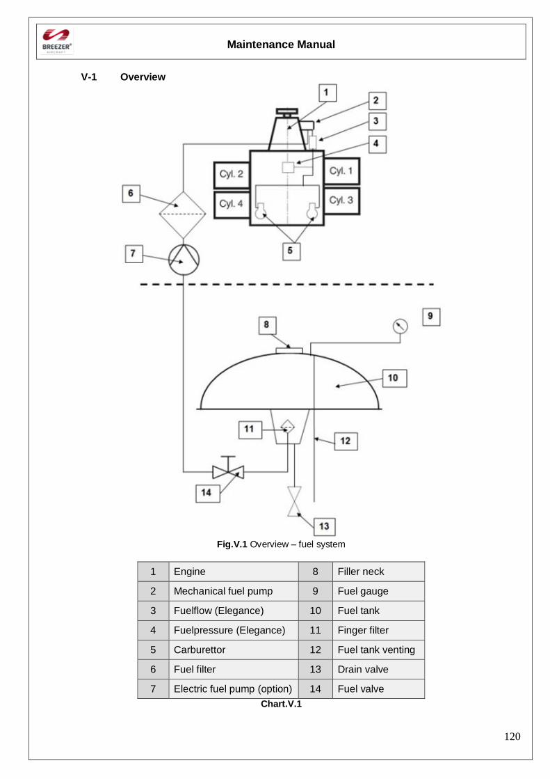
Maintenance Manual
120
V-1 Overview
Fig.V.1 Overview – fuel system
1 Engine 8 Filler neck
2 Mechanical fuel pump 9 Fuel gauge
3 Fuelflow (Elegance) 10 Fuel tank
4 Fuelpressure (Elegance) 11 Finger filter
5 Carburettor 12 Fuel tank venting
6 Fuel filter 13 Drain valve
7 Electric fuel pump (option) 14 Fuel valve
Chart.V.1
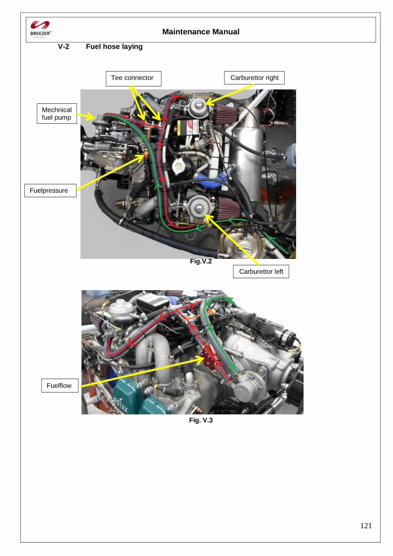
Maintenance Manual
121
V-2 Fuel hose laying
Fig.V.2
Fig. V.3
Carburettor right
Carburettor left
Mechnical fuel pump
Tee connector
Fuelpressure
Fuelflow
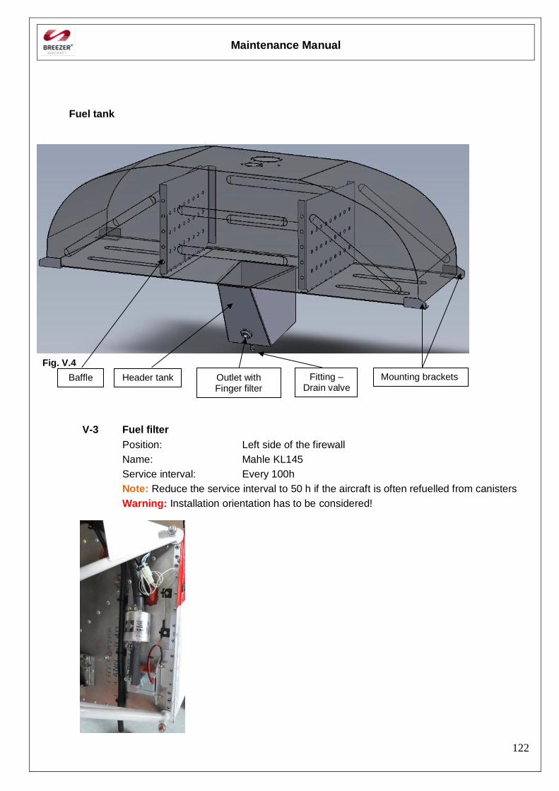
Maintenance Manual
122
Fuel tank
Fig. V.4
V-3 Fuel filter
Position: Left side of the firewall
Name: Mahle KL145
Service interval: Every 100h
Note: Reduce the service interval to 50 h if the aircraft is often refuelled from canisters
Warning: Installation orientation has to be considered!
Baffle Header tank Outlet with Finger filter
Fitting – Drain valve
Mounting brackets
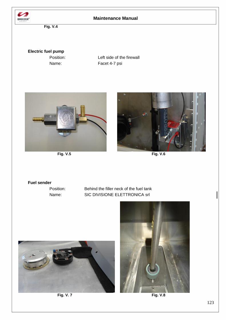
Maintenance Manual
123
Fig. V.4
Electric fuel pump
Position: Left side of the firewall
Name: Facet 4-7 psi
Fig. V.5 Fig. V.6
Fuel sender
Position: Behind the filler neck of the fuel tank
Name: SIC DIVISIONE ELETTRONICA srl
Fig. V. 7 Fig. V.8

Maintenance Manual
124
[Intentionally left blank]
Maintenance Manual
125
VI. Propeller
VI.1. General
VI.1.1. Ground adjustable Propeller
Manufacturer: DUC Swirl and Woodcomp Propuls
Model:
Diameter: Pitch: 21° at 75% radius
Maintenance Manual
126
VI.2. Inspection, removal, installation
VI.2.1. Inspection – Ground adjustable propeller
Information for outlined maintenance task
Type of maintenance: Line Maintenance
Recommended special tools: -
Parts needed: -
Note: It is strongly recommended to read carefully the Operating Manual of the propeller, latest revision, for further and more detailed information
The following points have to be checked:
- Firm fit of the blades and of all screws
- No play of the blade tips
- Damage to the blade surface?
- Minor damage to the coloured surface top layer does not impair the operation but:
o No cracks
o No damage to the fabric
- Hub must be free of cracks
Note: With composite propellers, minor damage to the external surface, such as a deep scratch which breaches the outside fabric, can result in significant loss of strength and a dangerous condition. For this reason it is important to inspect the blades carefully before flight. Look particularly for scratches along the chord of the blade which may have severed one or more yarns of fibre. When in doubt, seek expert advice.
All defective propeller components must be replaced with new parts obtained only from the manufacturer. Any defects must be reported to the Manufacturer via Defect and Fault Reporting Form included in this manual
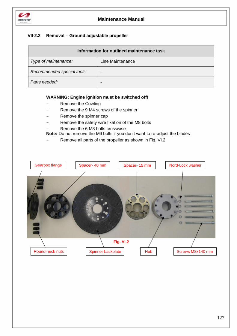
Maintenance Manual
127
VII-2.2 Removal – Ground adjustable propeller
Information for outlined maintenance task
Type of maintenance: Line Maintenance
Recommended special tools: -
Parts needed: -
WARNING: Engine ignition must be switched off!
- Remove the Cowling
- Remove the 9 M4 screws of the spinner
- Remove the spinner cap
- Remove the safety wire fixation of the M8 bolts
- Remove the 6 M8 bolts crosswise Note: Do not remove the M6 bolts if you don’t want to re-adjust the blades
- Remove all parts of the propeller as shown in Fig. VI.2
Fig. VI.2
Round-neck nuts
Gearbox flange Spacer- 40 mm
Spinner backplate
Spacer- 15 mm
Hub
Nord-Lock washer
Screws M8x140 mm
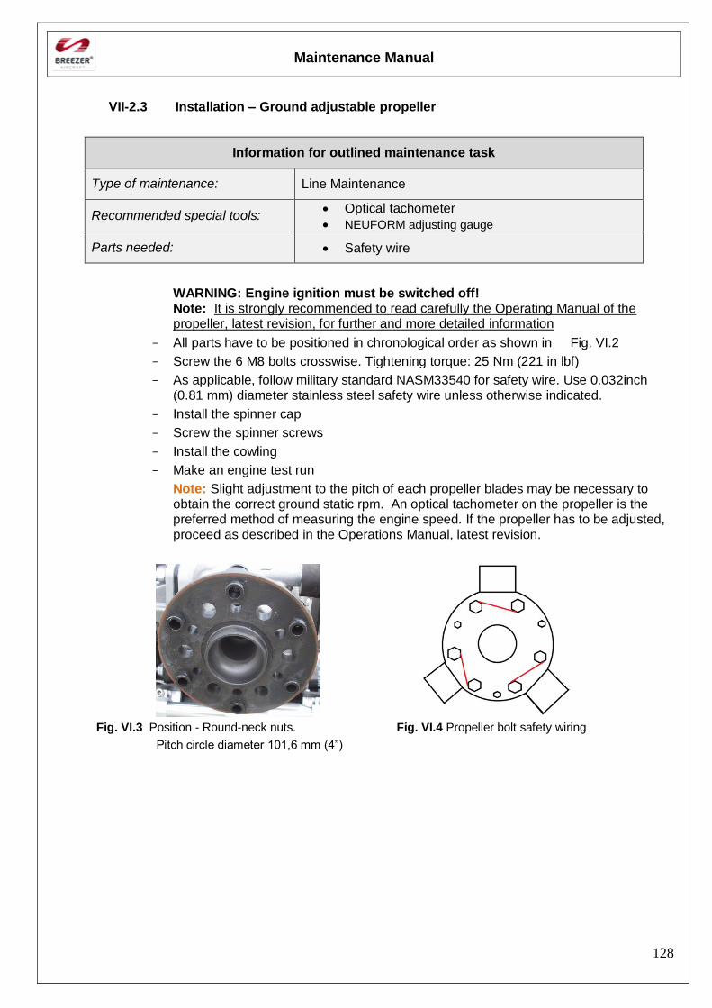
Maintenance Manual
128
VII-2.3 Installation – Ground adjustable propeller
Information for outlined maintenance task
Type of maintenance: Line Maintenance
Recommended special tools: Optical tachometer
NEUFORM adjusting gauge
Parts needed: Safety wire
WARNING: Engine ignition must be switched off! Note: It is strongly recommended to read carefully the Operating Manual of the propeller, latest revision, for further and more detailed information
- All parts have to be positioned in chronological order as shown in Fig. VI.2
- Screw the 6 M8 bolts crosswise. Tightening torque: 25 Nm (221 in lbf)
- As applicable, follow military standard NASM33540 for safety wire. Use 0.032inch (0.81 mm) diameter stainless steel safety wire unless otherwise indicated.
- Install the spinner cap
- Screw the spinner screws
- Install the cowling
- Make an engine test run
Note: Slight adjustment to the pitch of each propeller blades may be necessary to obtain the correct ground static rpm. An optical tachometer on the propeller is the preferred method of measuring the engine speed. If the propeller has to be adjusted, proceed as described in the Operations Manual, latest revision.
Fig. VI.3 Position - Round-neck nuts. Fig. VI.4 Propeller bolt safety wiring
Pitch circle diameter 101,6 mm (4”)
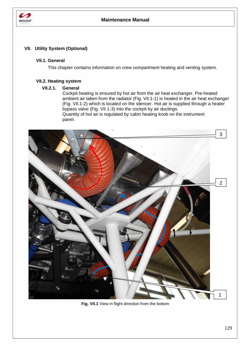
Maintenance Manual
129
VII. Utility System (Optional)
VII.1. General
This chapter contains information on crew compartment heating and venting system.
VII.2. Heating system
VII.2.1. General Cockpit heating is ensured by hot air from the air heat exchanger. Pre-heated ambient air taken from the radiator (Fig. VII.1-1) is heated in the air heat exchanger (Fig. VII.1-2) which is located on the silencer. Hot air is supplied through a heater bypass valve (Fig. VII.1-3) into the cockpit by air ductings. Quantity of hot air is regulated by cabin heating knob on the instrument panel.
Fig. VII.1 View in flight direction from the bottom
3
2
1
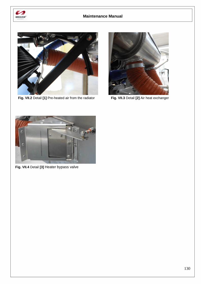
Maintenance Manual
130
Fig. VII.2 Detail [1] Pre-heated air from the radiator Fig. VII.3 Detail [2] Air heat exchanger
Fig. VII.4 Detail [3] Heater bypass valve
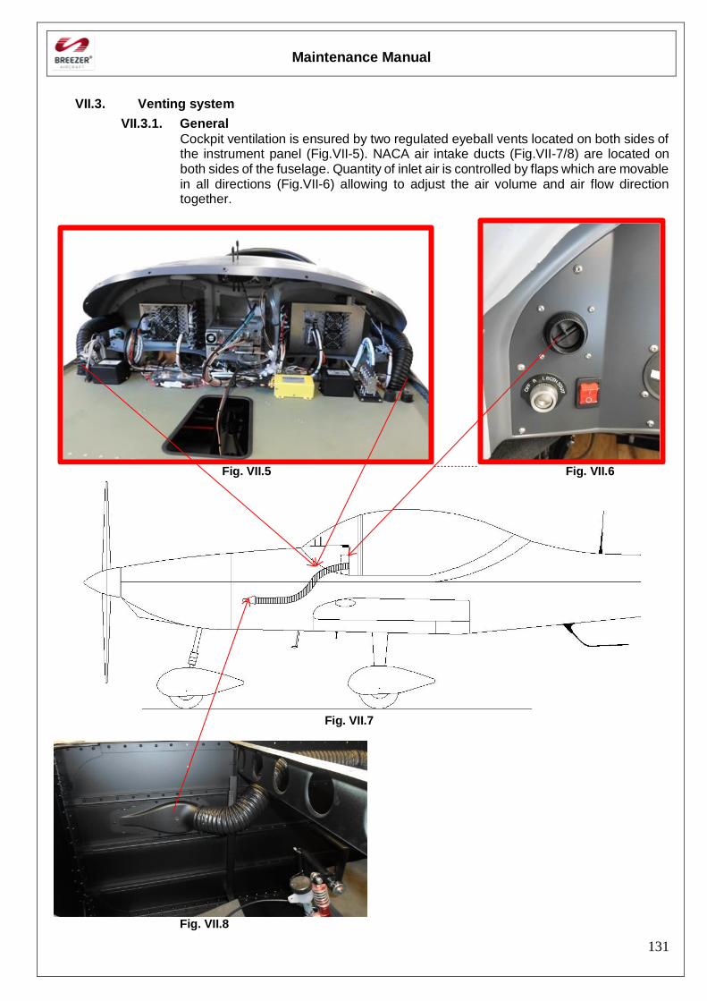
Maintenance Manual
131
VII.3. Venting system
VII.3.1. General
Cockpit ventilation is ensured by two regulated eyeball vents located on both sides of the instrument panel (Fig.VII-5). NACA air intake ducts (Fig.VII-7/8) are located on both sides of the fuselage. Quantity of inlet air is controlled by flaps which are movable in all directions (Fig.VII-6) allowing to adjust the air volume and air flow direction together.
Fig. VII.5 Fig. VII.6
Fig. VII.7
Fig. VII.8

Maintenance Manual
132
[Intentionally left blank]
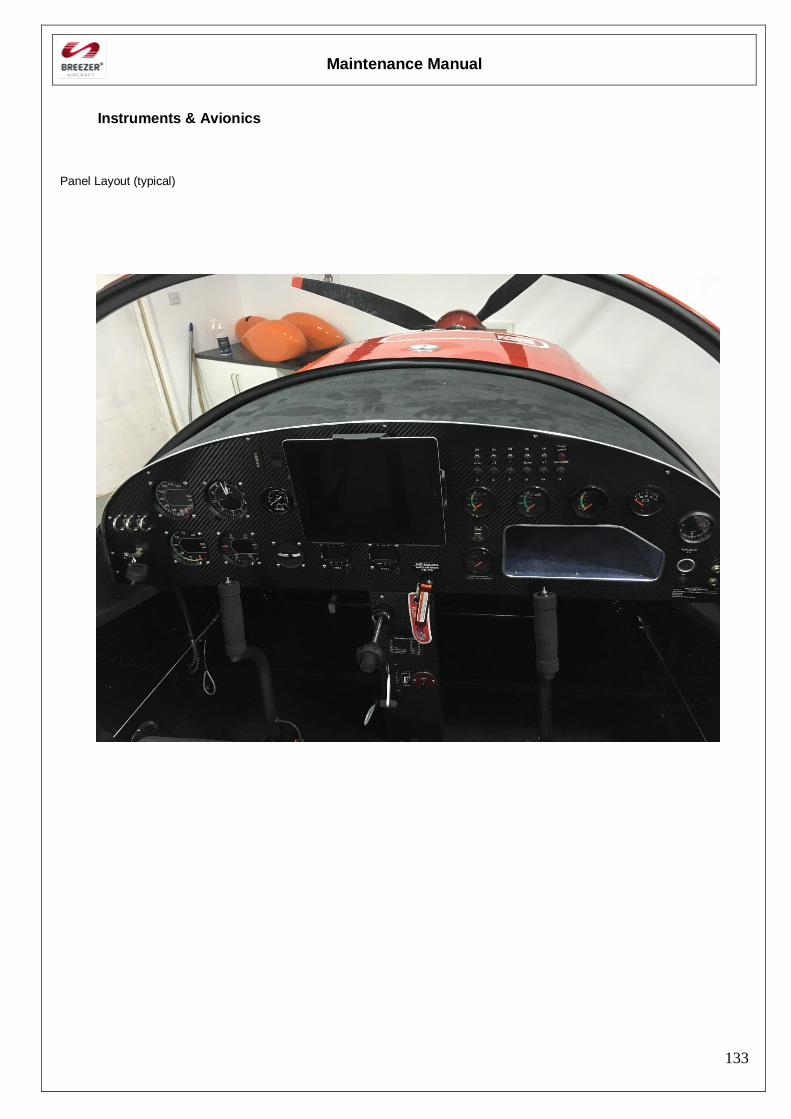
Maintenance Manual
133
Instruments & Avionics
Panel Layout (typical)
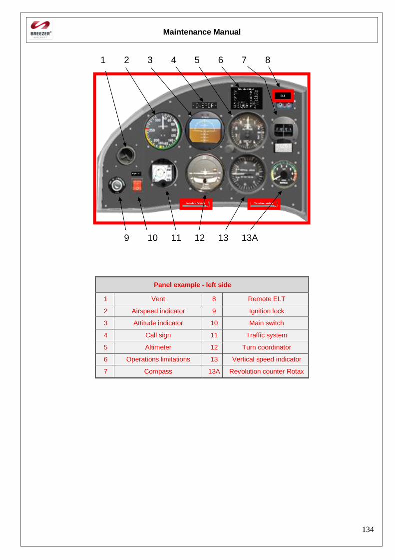
Maintenance Manual
134
1 2 3 4 5 6 7 8
9 10 11 12 13 13A
Panel example - left side
1 Vent 8 Remote ELT
2 Airspeed indicator 9 Ignition lock
3 Attitude indicator 10 Main switch
4 Call sign 11 Traffic system
5 Altimeter 12 Turn coordinator
6 Operations limitations 13 Vertical speed indicator
7 Compass 13A Revolution counter Rotax
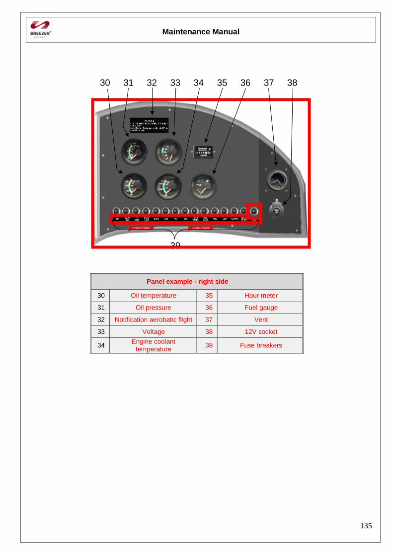
Maintenance Manual
135
30 31 32 33 34 35 36 37 38
39
Panel example - right side
30 Oil temperature 35 Hour meter
31 Oil pressure 36 Fuel gauge
32 Notification aerobatic flight 37 Vent
33 Voltage 38 12V socket
34 Engine coolant
temperature 39 Fuse breakers
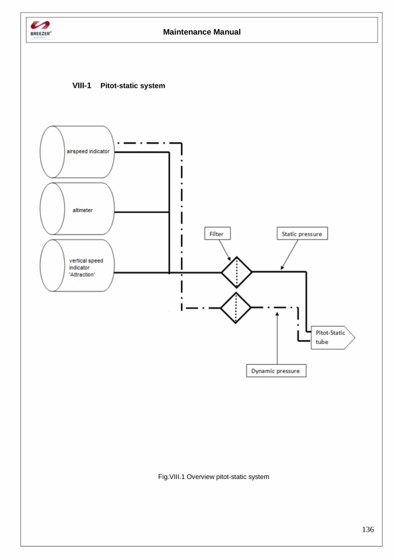
Maintenance Manual
136
VIII-1 Pitot-static system
Fig.VIII.1 Overview pitot-static system
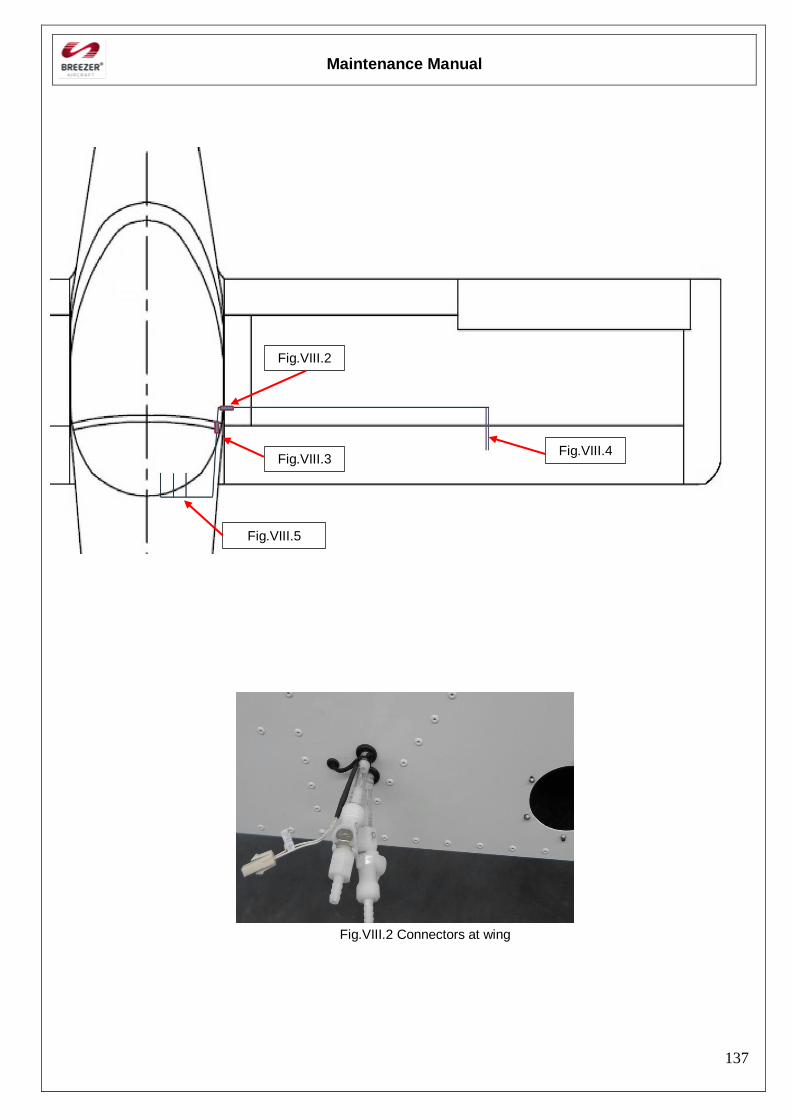
Maintenance Manual
137
Fig.VIII.2 Connectors at wing
Fig.VIII.5
Fig.VIII.3 Fig.VIII.4
Fig.VIII.2
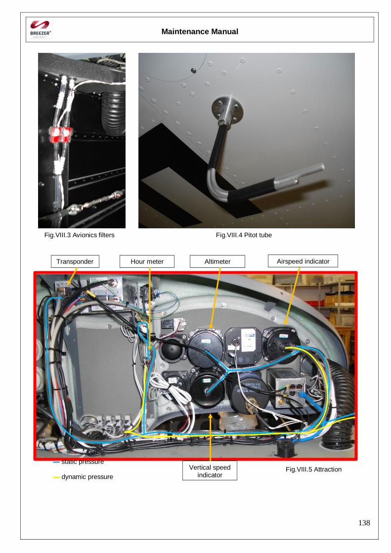
Maintenance Manual
138
Fig.VIII.3 Avionics filters Fig.VIII.4 Pitot tube
▬ static pressure Fig.VIII.5 Attraction ▬ dynamic pressure
Transponder Hour meter Altimeter Airspeed indicator
Vertical speed indicator
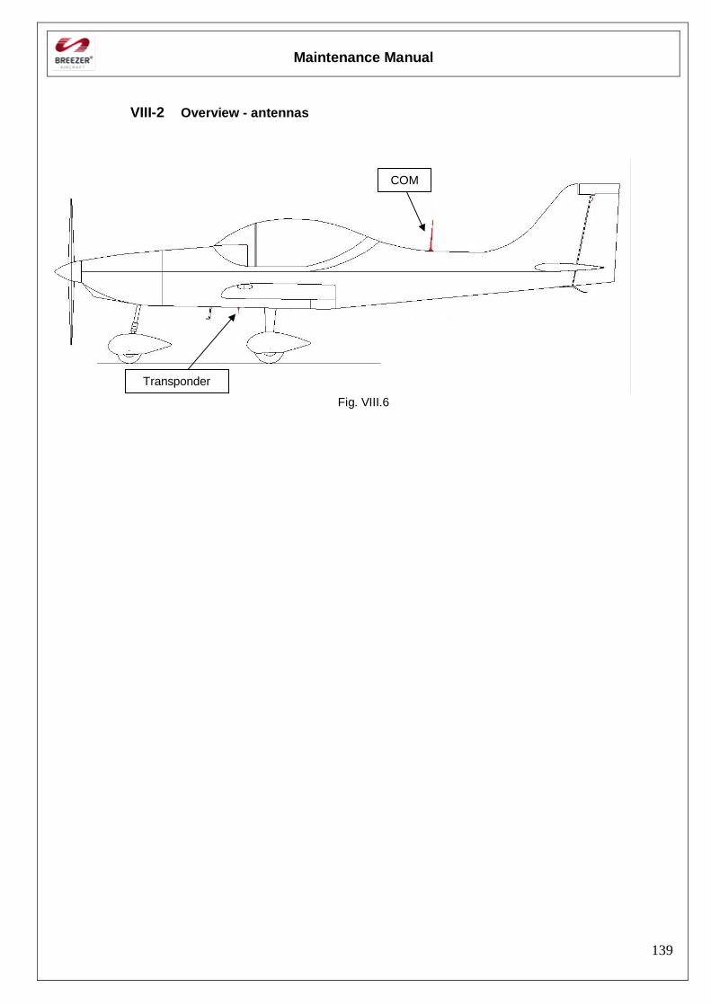
Maintenance Manual
139
VIII-2 Overview - antennas
Fig. VIII.6
COM
Transponder
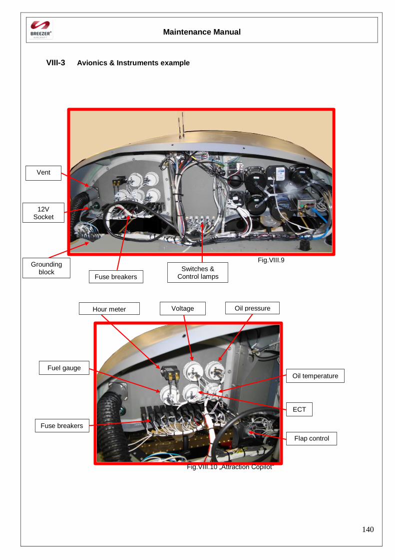
Maintenance Manual
140
VIII-3 Avionics & Instruments example
Fig.VIII.9
Fig.VIII.10 „Attraction Copilot“
Hour meter Voltage Oil pressure
12V Socket
Grounding block
Vent
Fuse breakers
ECT
Fuse breakers
Fuel gauge
Switches & Control lamps
Oil temperature
Flap control
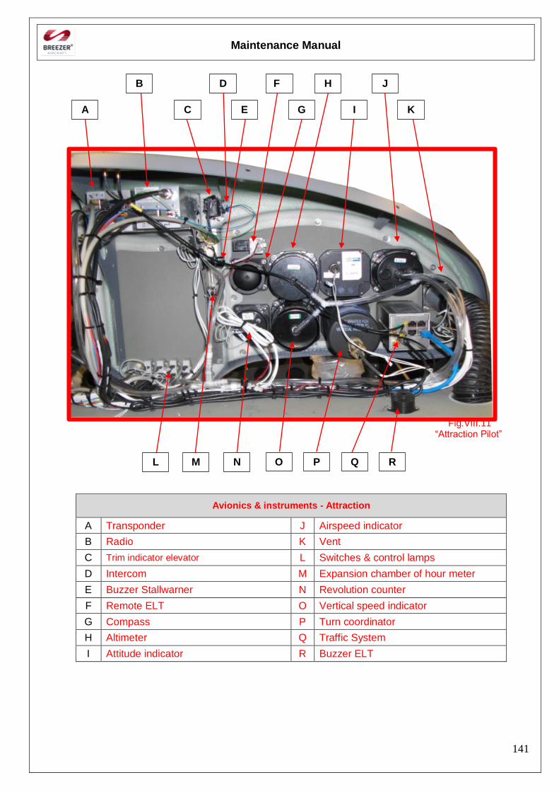
Maintenance Manual
141
Fig.VIII.11 “Attraction Pilot”
Avionics & instruments - Attraction
A Transponder J Airspeed indicator
B Radio K Vent
C Trim indicator elevator L Switches & control lamps
D Intercom M Expansion chamber of hour meter
E Buzzer Stallwarner N Revolution counter
F Remote ELT O Vertical speed indicator
G Compass P Turn coordinator
H Altimeter Q Traffic System
I Attitude indicator R Buzzer ELT
A
B
C
D
E
F
G
H
I
J
K
L M N O P Q R
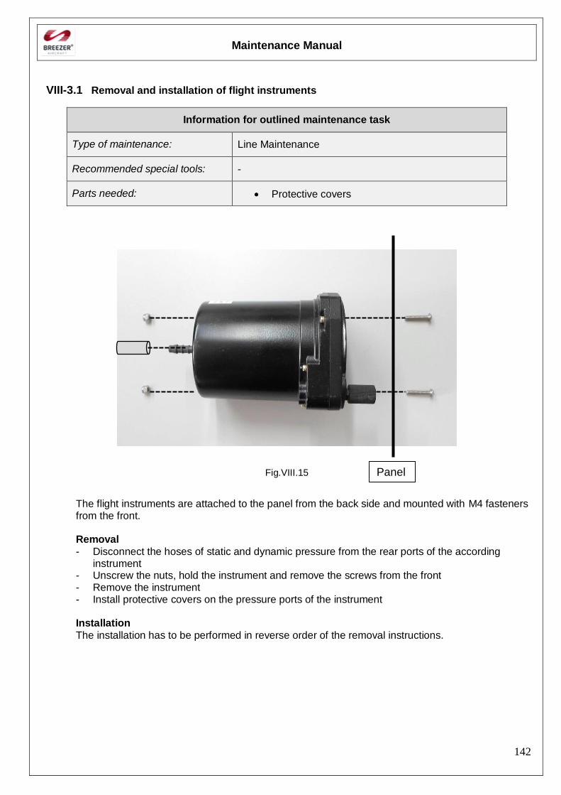
Maintenance Manual
142
VIII-3.1 Removal and installation of flight instruments
Information for outlined maintenance task
Type of maintenance: Line Maintenance
Recommended special tools: -
Parts needed: Protective covers
Fig.VIII.15
The flight instruments are attached to the panel from the back side and mounted with M4 fasteners from the front.
Removal
- Disconnect the hoses of static and dynamic pressure from the rear ports of the according instrument
- Unscrew the nuts, hold the instrument and remove the screws from the front - Remove the instrument - Install protective covers on the pressure ports of the instrument Installation
The installation has to be performed in reverse order of the removal instructions.
Panel
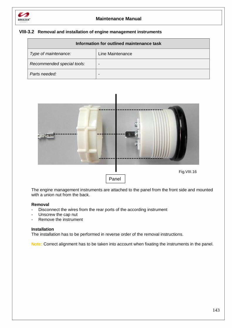
Maintenance Manual
143
VIII-3.2 Removal and installation of engine management instruments
Information for outlined maintenance task
Type of maintenance: Line Maintenance
Recommended special tools: -
Parts needed: -
Fig.VIII.16
The engine management instruments are attached to the panel from the front side and mounted with a union nut from the back.
Removal
- Disconnect the wires from the rear ports of the according instrument - Unscrew the cap nut - Remove the instrument Installation
The installation has to be performed in reverse order of the removal instructions. Note: Correct alignment has to be taken into account when fixating the instruments in the panel.
Panel
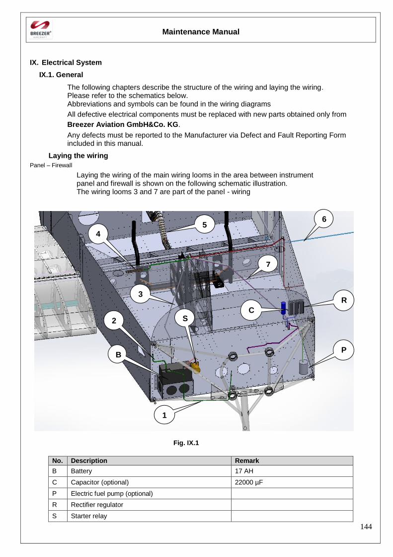
Maintenance Manual
144
IX. Electrical System
IX.1. General
The following chapters describe the structure of the wiring and laying the wiring. Please refer to the schematics below. Abbreviations and symbols can be found in the wiring diagrams
All defective electrical components must be replaced with new parts obtained only from
Breezer Aviation GmbH&Co. KG.
Any defects must be reported to the Manufacturer via Defect and Fault Reporting Form included in this manual.
Laying the wiring
Panel – Firewall
Laying the wiring of the main wiring looms in the area between instrument panel and firewall is shown on the following schematic illustration. The wiring looms 3 and 7 are part of the panel - wiring
Fig. IX.1
No. Description Remark
B Battery 17 AH
C Capacitor (optional) 22000 µF
P Electric fuel pump (optional)
R Rectifier regulator
S Starter relay
6
R
S
P
4
2
7
C
3
1
B
5
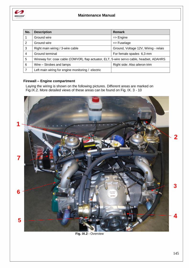
Maintenance Manual
145
No. Description Remark
1 Ground wire => Engine
2 Ground wire => Fuselage
3 Right main wiring / 3-wire cable Ground, Voltage 12V, Wiring - relais
4 Ground terminal For female spades 6,3 mm
5 Wireway for: coax cable (COM/VOR), flap actuator, ELT, 5-wire servo cable, headset, ADAHRS
6 Wire – Strobes and lamps Right side: Also aileron trim
7 Left main wiring for engine monitoring / -electric
Firewall – Engine compartment
Laying the wiring is shown on the following pictures. Different areas are marked on Fig.IX.2. More detailed views of these areas can be found on Fig. IX. 3 - 10
Fig. IX.2 - Overview
1
2
4
3
5
6
7
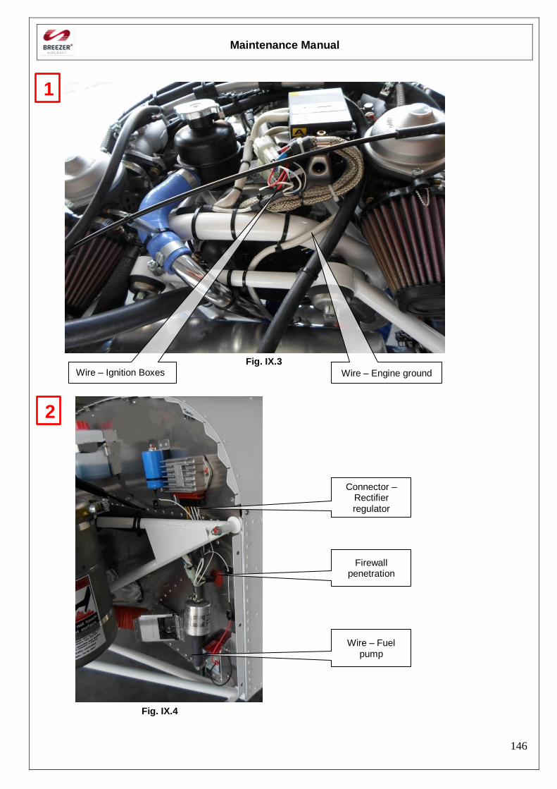
Maintenance Manual
146
Fig. IX.3
Fig. IX.4
1
2
Wire – Ignition Boxes Wire – Engine ground
Connector – Rectifier regulator
Wire – Fuel pump
Firewall penetration
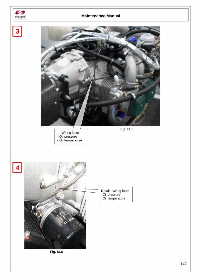
Maintenance Manual
147
Fig. IX.5
Fig. IX.6
3
Wiring loom - Oil pressure - Oil temperature
4
Detail - wiring loom - Oil pressure - Oil temperature
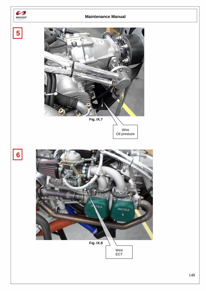
Maintenance Manual
148
Fig. IX.7
Fig. IX.8
Wire Oil pressure
Wire ECT
6
5
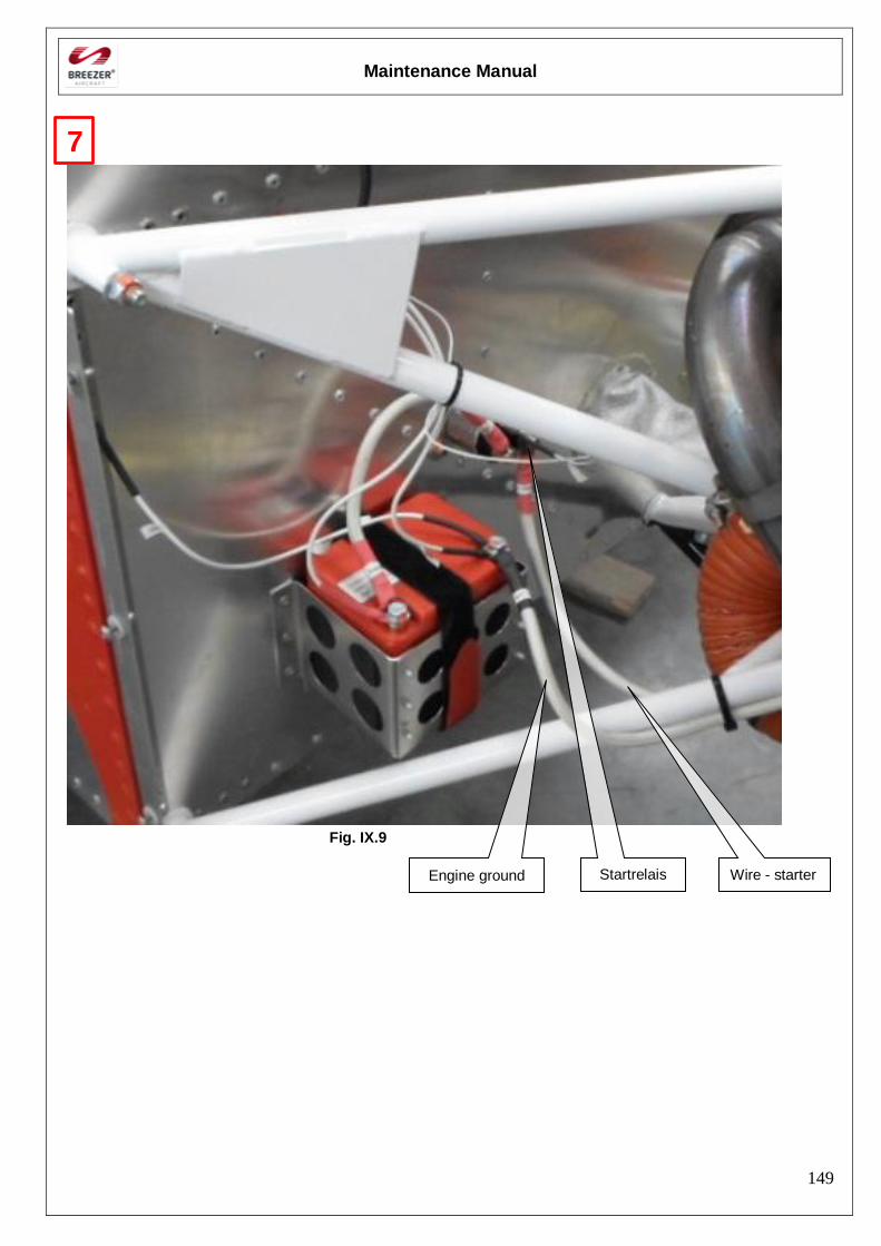
Maintenance Manual
149
Fig. IX.9
Engine ground Wire - starter Startrelais
7
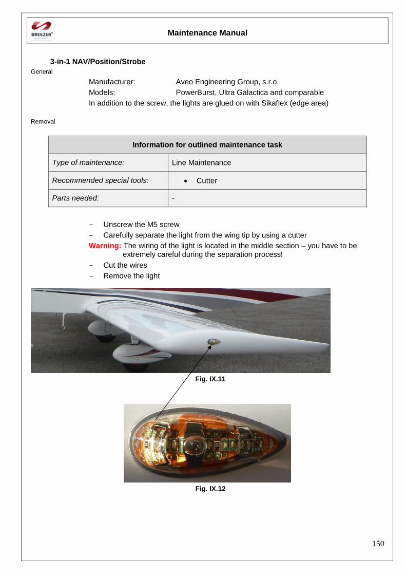
Maintenance Manual
150
3-in-1 NAV/Position/Strobe
General
Manufacturer: Aveo Engineering Group, s.r.o.
Models: PowerBurst, Ultra Galactica and comparable
In addition to the screw, the lights are glued on with Sikaflex (edge area)
Removal
Information for outlined maintenance task
Type of maintenance: Line Maintenance
Recommended special tools: Cutter
Parts needed: -
- Unscrew the M5 screw
- Carefully separate the light from the wing tip by using a cutter
Warning: The wiring of the light is located in the middle section – you have to be extremely careful during the separation process!
- Cut the wires
- Remove the light
Fig. IX.11
Fig. IX.12
Maintenance Manual
151
IX.2.1. Installation
Information for outlined maintenance task
Type of maintenance: Line Maintenance
Recommended special tools: -
Parts needed: Shrink-on tube
Sikaflex 221 adhesive
- Put a shrink-on tube on the wiring loom located in the wing
- Put a shrink-on tube on each wire
- Splice the wires by using a crimp connector
- Cover each connector with the shrink-on tube
- Cover all shrink-on tubes with the main shrink-on tube
- Put Sikaflex 221 adhesive on the edge area of the light
- Screw the M5 screw
- Carefully remove the squeezed out adhesive
Maintenance Manual
152
27. Wiring diagram
General
This chapter contains the standard wiring diagram of the Breezer. For a clearer view, the diagram is split into separate pages.
Wiring diagram

Maintenance Manual
153

Maintenance Manual
154
[Intentionally left blank]
Maintenance Manual
155
28. Structural repairs
General
Maintenance of the structural system is in accordance with the Inspection schedule in Section 1 – Inspections. No structural repairs can take place without the direct authorization of the manufacturer. All structural repairs must be completed using only with new parts obtained only from the manufacturer. Never straighten bent tubes or bracket assemblies, replace with new parts only. Never re-weld any parts. Unless otherwise specified in this Chapter, all repairs have to be carried out in accordance to the most current edition of FAA AC 43.13-1B and AC 43.13-2A, Acceptable Methods, Techniques, and Practices - Aircraft Inspection and Repair.
Rivets
Due to the fact the different kinds of blind rivets are used for almost every structural part of the Breezer, it is strongly recommended to use rivets obtained only from the manufacturer. The following different materials are used:
- Sleeve: Aluminium Mandrel: Steel Short form: Al/St
- Sleeve: Steel Mandrel: Steel Short form: St/St
- Sleeve: Stainless steel Mandrel: Stainless steel Short form: A2/A2
In case that different replacement rivets shall be used, it is important to use rivets with identical dimensions and material characteristics such as strength (shear/tensile), head design and blind side design (e.g. closed end)
Removing rivets
Information for outlined maintenance task
Type of maintenance: Heavy Maintenance
Recommended special tools: Drift pins
Parts needed: -
- Drive out the rivet mandrel using steel drift pin of proper size (A)
- Drill nearly through the head of the rivet using a drill the same size as the rivet sleeve (B)
- Break off rivet head using drift pin as a pry (C)
- Drive out the remaining sleeve with a drift pin having the same size as the rivet sleeve (D)
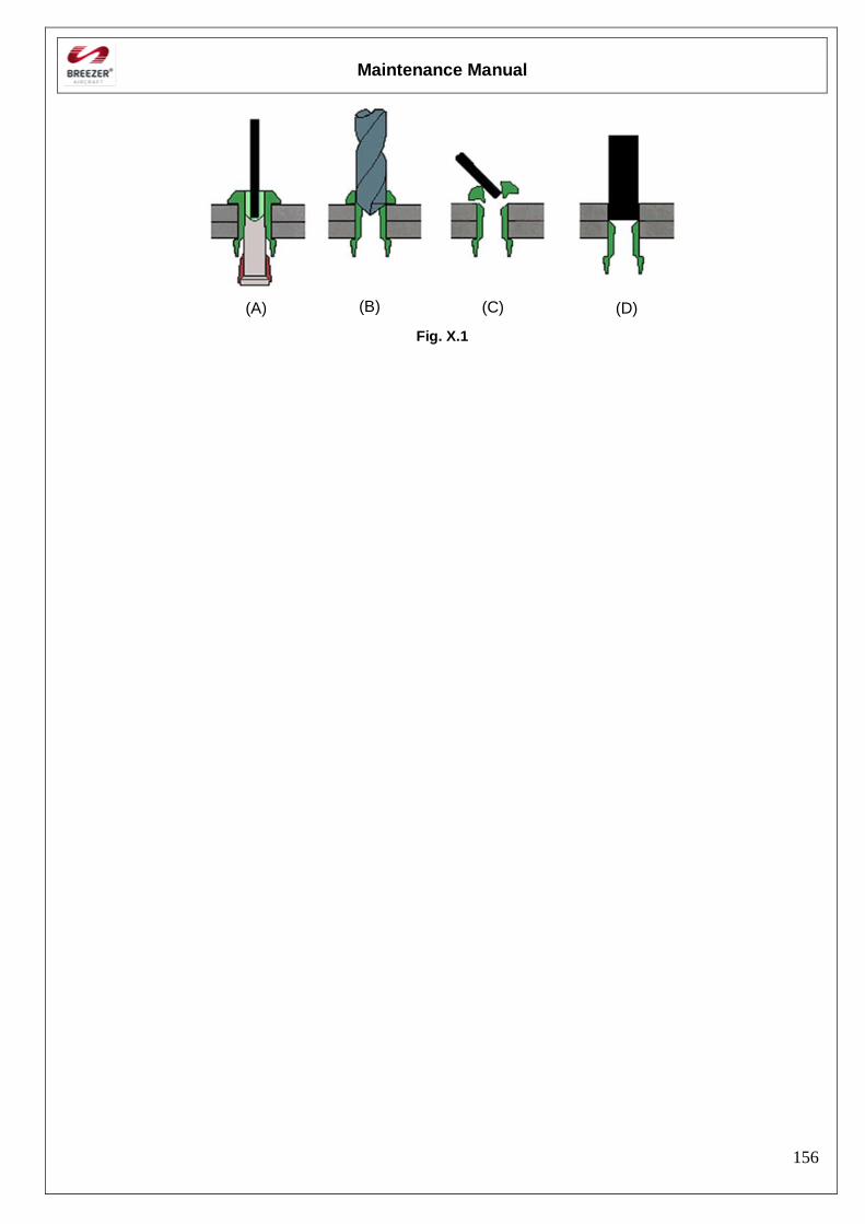
Maintenance Manual
156
Fig. X.1
(A) (B) (C) (D)
Maintenance Manual
157
Riveting
Information for outlined maintenance task
Type of maintenance: Heavy Maintenance
Recommended special tools: Hand riveter or pneumatic/electric rivet gun
Clamps or clecos
Parts needed: Epoxy primer
Sanding material
Note: It is strongly recommended to use an adequate hand riveter or a
pneumatic/electric rivet gun with the respective nosepiece for the rivet.
- Fit the parts being connected and drill them together. The diameter of the drill hole must be by 0,1 mm (0,004 in) bigger than the rivet sleeve diameter. The correct size of the drill can be found on the packing of the rivets
- When drilling, fix by clamps or clecos mutual position of assembled parts.
- It is recommended to pre-drill holes of diameters > 8,0 mm with a drill bit of smaller diameter and then redrill them to the final size.
- Disassemble the parts and deburr the holes
- For good adhesion it is necessary to do sanding with sanding material having a grain size of 240 - 320.
- Clean the connected parts of impurities and degrease contact surfaces by appropriate agent, e.g. industrial spirit.
- Apply epoxy primer by spraying
- Fix the parts by means of clecos and rivet them.
Note: The hand riveter or rivet gun must be held perpendicular to the surface
Maintenance Manual
158
Skin repairs
Information for outlined maintenance task
Type of maintenance: Heavy Maintenance
Recommended special tools:
Hand riveter or pneumatic/electric rivet gun
Clamps or clecos
Jigs for structural support
Parts needed: Rivets
Aluminum patches of appropriate thickness and alloys
Remove damaged skins
In case that it is necessary to replace bigger parts of the skin, ensure reliable support of the structure. Appropriately support the damaged area of the fuselage or the wing by a jig located in the area of fuselage frames or wing ribs. The shape of the jig must correspond with the shape of the supported place and should be covered with protection material, so that skin surface cannot be damaged. Remove rivets according to X.3
Principles for repair method determination
When repairing the damaged skin or structure pay attention to the following principles:
- Drill of the loose or damaged rivets and replace them with new rivets
- Strength in any section of the repaired place must be as a minimum equal to the strength of the original part.
- Use the same material for repairs as the material of a defective area (for survey of used materials
- Repairs of skin damaging have to be carried out by means of patches having the same thickness as the original skin or higher.
- Loading from one side of the repaired area must be carried through the repair element directly to the other side.
- Length of overlapping in the area of repair must be satisfactorily big so that loading can be equally distributed to nondefective part of the structure.
- Existing holes are, if possible, used for riveted joints. If these rivets are not able to transfer loading, drill other holes. Rivets around of the repaired area are a criterion for rivet size selection.
- Standard minimum distances of rivets from the edge of sheet metals or inserted bands have to be considered
Maintenance Manual
159
Stopping cracks
Enlarging of small cracks can be stopped by drilling a hole with a drill bit of dia. 3,2 mm (1/8 in) at the utmost end of the crack. If enlarging continues, repeat the drilling. Support the place of drilling with a wooden block while drilling thin skin and use a sharp drill bit so that it will not drift or cause another damage to the skin. Check at short intervals whether the crack was successfully stopped. When drilling a crack of the skin in the area of a flange, supporting stiffener etc., protect adjacent parts before drilling by supporting the drilled place by means of a thin aluminium or steel band. If the crack still enlarges after repeated drilling, cut out the affected area and repair the skin by means of a patch
Repair of fiberglass parts
Information for outlined maintenance task
Type of maintenance: Heavy Maintenance
Recommended special tools: Sanding material (grain size 160 - 400)
Parts needed:
Epoxy resin
Glass/carbon stiffeners
Putty
Paint
General
Any damage of fiberglass parts lead to increased saturation of the matrix with humidity and subsequently to loss of properties. Therefore we recommend carrying out their repair as soon as possible after the damage has occurred. Take into consideration that in most cases it makes sense to replace the parts instead of a repair.
Two kinds of parts are made from these materials in the airplane:
- Structural, load-bearing parts (vertical stabilizer, landing gear)
- Forming, non load-bearing parts (e.g. fairings)
According to the damage size we can divide repairs into:
- Small damages (surface defects, not affecting the stiffeners)
- Medium damages (not more than 2/3 of stiffener thickness damaged)
- Big damages We recommend carry out repairs by means of epoxy resin and glass or carbon stiffeners. It is strongly recommended to contact the manufacturer for further information in any case.
Maintenance Manual
160
Small damages of forming parts
Scratches down to the top layer can be repaired just by application of putty and varnish repair. In case of small cracks and other damages proceed as follows:
- For a good adhesion of repair layers it is important to carry out surface sanding with an overrun of ~ 51 mm (~2 in) from the damage area smoothly to the top layer. It is suitable to do sanding with a grain size of 160. Dry sanding equipment with suction from the sanding area should be used.
- Accurately clean the area from dust and other impurities
- Apply the resin onto the repair area by means of a spatula or brush.
Note: Mixing the resin with hardener and eventual thickening (Microballs/Aerosil) has to be done very careful.
- After proper application the layer should be without bubbles
- Sanding with grain sizes from 160 up to of at least 240 can be performed after the drying process is completed.
- Apply putty on the area
- Sand it with grain sizes from 160 up to of at least 400
- Paint the area
Torque moments
Unless otherwise prescribed, the torque moments shown in Chapter I-13 can be used. Specific tightening torque moments are listed in Chapter I-14. These values are binding and have to be taken into account. When tightening follows several rules:
- Unless specifically stated do not grease neither nut nor bolt.
- If possible always tighten the nut. If for some space reasons it is necessary to tighten the bolt head and the scope of tightening moment is defined. Use higher moment for tightening.
- Maximum moments are used only for the materials and surfaces, which have a sufficient thickness, area and strength resistant to bursting, warping or other damage.
Note: Do not exceed maximum tightening moments.
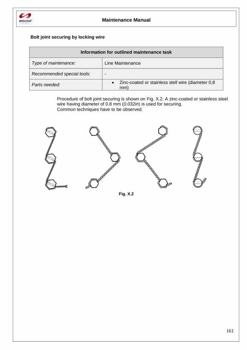
Maintenance Manual
161
Bolt joint securing by locking wire
Information for outlined maintenance task
Type of maintenance: Line Maintenance
Recommended special tools: -
Parts needed: Zinc-coated or stainless stell wire (diameter 0,8
mm)
Procedure of bolt joint securing is shown on Fig. X.2. A zinc-coated or stainless steel wire having diameter of 0.8 mm (0.032in) is used for securing.
Common techniques have to be observed.
Fig. X.2
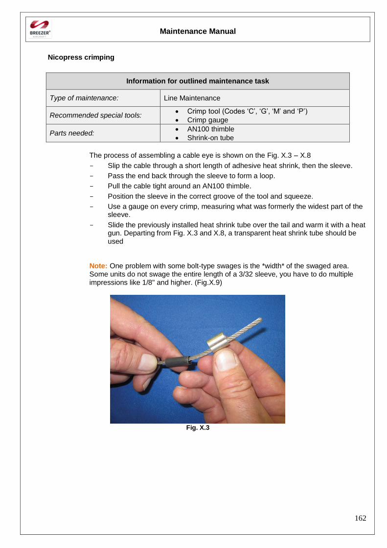
Maintenance Manual
162
Nicopress crimping
Information for outlined maintenance task
Type of maintenance: Line Maintenance
Recommended special tools: Crimp tool (Codes ‘C’, ‘G’, ‘M’ and ‘P’)
Crimp gauge
Parts needed: AN100 thimble
Shrink-on tube
The process of assembling a cable eye is shown on the Fig. X.3 – X.8
- Slip the cable through a short length of adhesive heat shrink, then the sleeve.
- Pass the end back through the sleeve to form a loop.
- Pull the cable tight around an AN100 thimble.
- Position the sleeve in the correct groove of the tool and squeeze.
- Use a gauge on every crimp, measuring what was formerly the widest part of the sleeve.
- Slide the previously installed heat shrink tube over the tail and warm it with a heat gun. Departing from Fig. X.3 and X.8, a transparent heat shrink tube should be used
Note: One problem with some bolt-type swages is the *width* of the swaged area. Some units do not swage the entire length of a 3/32 sleeve, you have to do multiple impressions like 1/8" and higher. (Fig.X.9)
Fig. X.3
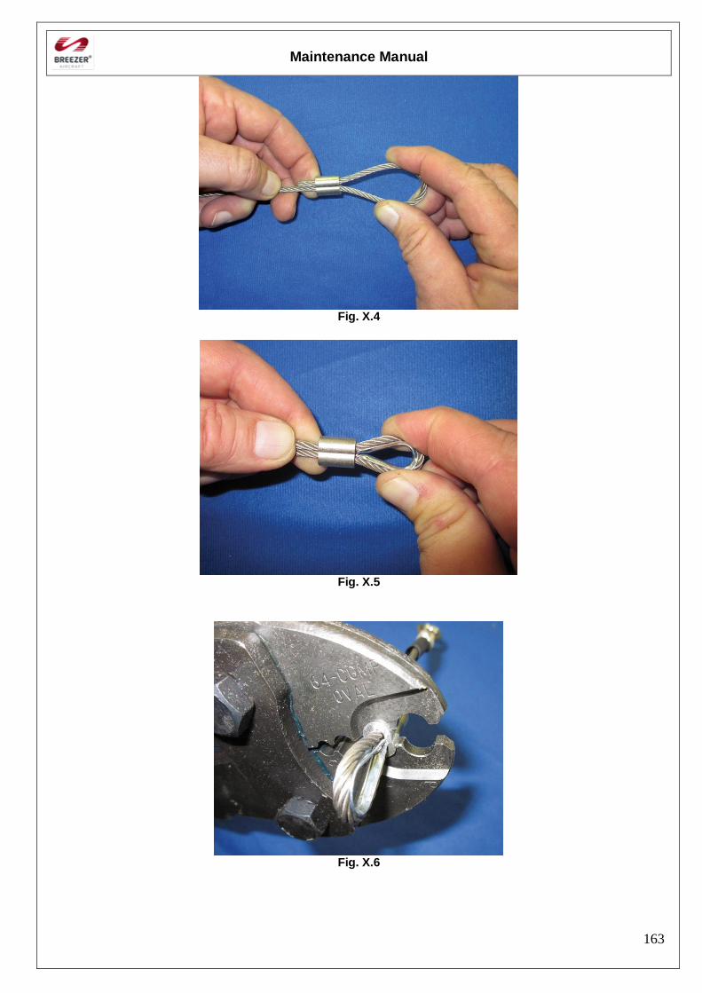
Maintenance Manual
163
Fig. X.4
Fig. X.5
Fig. X.6
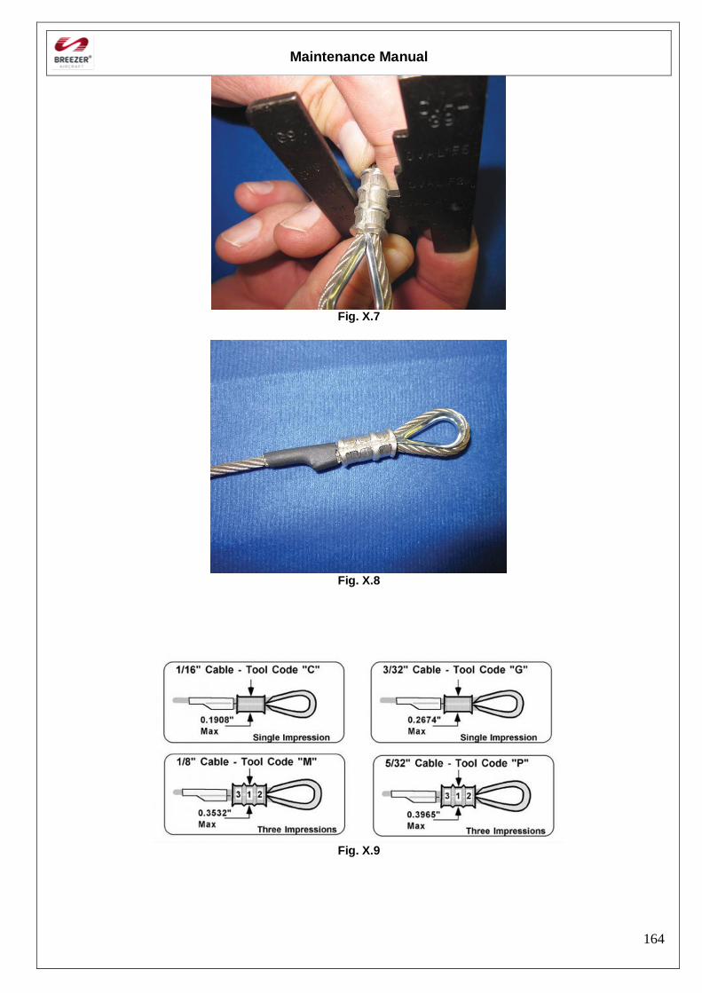
Maintenance Manual
164
Fig. X.7
Fig. X.8
Fig. X.9
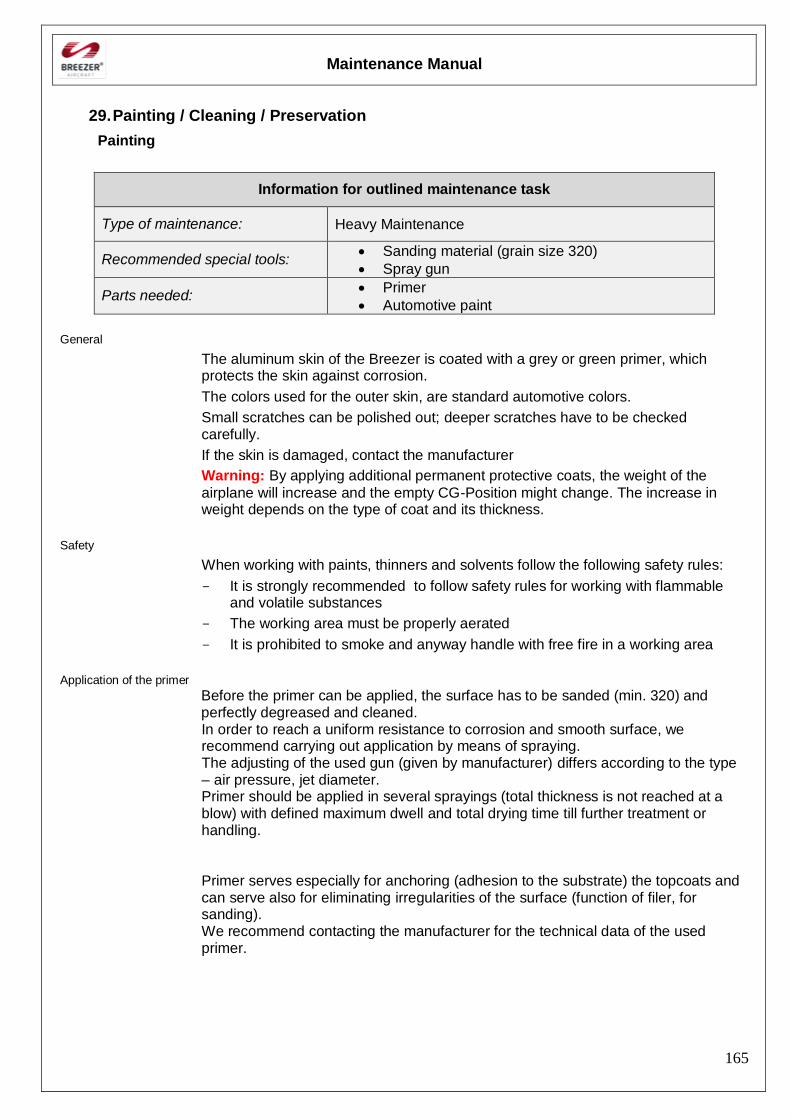
Maintenance Manual
165
29. Painting / Cleaning / Preservation
Painting
Information for outlined maintenance task
Type of maintenance: Heavy Maintenance
Recommended special tools: Sanding material (grain size 320)
Spray gun
Parts needed: Primer
Automotive paint
General
The aluminum skin of the Breezer is coated with a grey or green primer, which protects the skin against corrosion.
The colors used for the outer skin, are standard automotive colors.
Small scratches can be polished out; deeper scratches have to be checked carefully.
If the skin is damaged, contact the manufacturer
Warning: By applying additional permanent protective coats, the weight of the
airplane will increase and the empty CG-Position might change. The increase in weight depends on the type of coat and its thickness.
Safety
When working with paints, thinners and solvents follow the following safety rules:
- It is strongly recommended to follow safety rules for working with flammable and volatile substances
- The working area must be properly aerated
- It is prohibited to smoke and anyway handle with free fire in a working area
Application of the primer
Before the primer can be applied, the surface has to be sanded (min. 320) and perfectly degreased and cleaned. In order to reach a uniform resistance to corrosion and smooth surface, we recommend carrying out application by means of spraying. The adjusting of the used gun (given by manufacturer) differs according to the type – air pressure, jet diameter. Primer should be applied in several sprayings (total thickness is not reached at a blow) with defined maximum dwell and total drying time till further treatment or handling. Primer serves especially for anchoring (adhesion to the substrate) the topcoats and can serve also for eliminating irregularities of the surface (function of filer, for sanding). We recommend contacting the manufacturer for the technical data of the used primer.
Maintenance Manual
166
Application of the top coat
In order to reach smooth surface we recommend carrying out the paint coat by spraying. Topcoat serves especially for creating the coat resistant to weather and external effects for aesthetic rendering of the unit. Considering the higher loading by external effects we recommend to use the type of colors that are recommended by the manufacturer.
Cleaning
Information for outlined maintenance task
Type of maintenance: Line Maintenance
Recommended special tools: Tarpaulin
Parts needed: Clean water
Mild detergent
The aircraft should be cleaned at the end of each day of flight. Insects and light dirt are best removed using clear water, for more persistent dirt a mild detergent may be added to the water. Depending upon type of operation and weather conditions the painted surfaces should be polished and waxed at least once a year. One should avoid parking the aeroplane for longer periods in the bright sunlight or in rain; if necessary, use a tarpaulin to protect the aircraft from the weather. Avoid the use of a pressure washer or garden hose as this can introduce water into places it shouldn’t go, (engine, fuel tank, pitot head, pilot’s seat).
Procedure for cleaning seat covers and upholstery:
- Take upholstery and covers out of the airplane
- Brush impurities, possibly clean with warm water with addition of a suitable detergent.
- Before reinstalling upholstery and seats in the airplane, let it thoroughly dry.
Maintenance Manual
167
Preservation
Information for outlined maintenance task
Type of maintenance: Line Maintenance
Recommended special tools: Air compressor with tube, nozzle and rod probe
spraying attachments
Parts needed: ACF-50 anticorrosion lubricant
General
Corrosion simply stated is a natural phenomenon which destroys most metals by either a chemical or electrochemical reaction. The metal is converted, usually with the help of an electrolyte, into a stable metallic compound such as an oxide, hydroxide, or sulfate. The rate at which metals corrode depends greatly on the environment they are exposed to, and the amount of preventive maintenance they receive. Metals that are exposed to marine atmospheres, moisture, tropical temperatures, and industrial chemical atmospheres have the highest rate of corrosion. The tendency of metals to corrode creates a serious problem in the area of aircraft operation. The whole inner structure of the Breezer is protected by the use of an epoxy primer. In addition to this, an anticorrosion lubricant compound is sprayed into every part of the structure. It is recommended to repeat this process every 24 months. The best experiences have been made with ACF-50 anti-corrosion formula, which
is a state-of-the-art anticorrosion lubricant compound specifically designed for the Aerospace industry. It is an ultra-thin fluid compound that actively treats metal using advanced polar bonding technology Note: Preservation should be performed in the open!
Airplane preparation
- Open all inspection cover plates
- Air pressure max. 4 bar
- Shake up ACF-50 accurately
- Required quantity: Approx. 1 Ltr.
- It is recommended to orientate the airplane into the wind
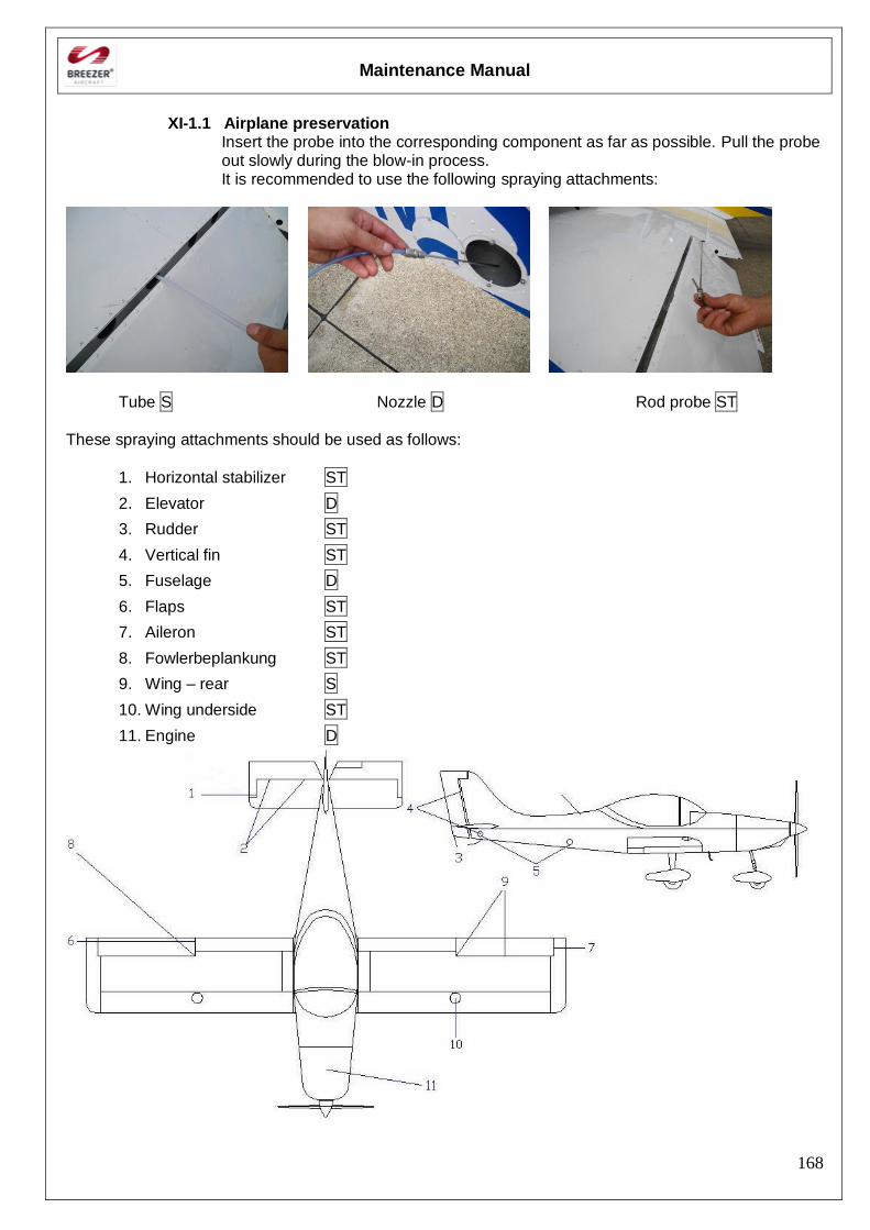
Maintenance Manual
168
XI-1.1 Airplane preservation
Insert the probe into the corresponding component as far as possible. Pull the probe out slowly during the blow-in process. It is recommended to use the following spraying attachments:
Tube S Nozzle D Rod probe ST
These spraying attachments should be used as follows:
1. Horizontal stabilizer ST
2. Elevator D
3. Rudder ST
4. Vertical fin ST
5. Fuselage D
6. Flaps ST
7. Aileron ST
8. Fowlerbeplankung ST
9. Wing – rear S
10. Wing underside ST
11. Engine D
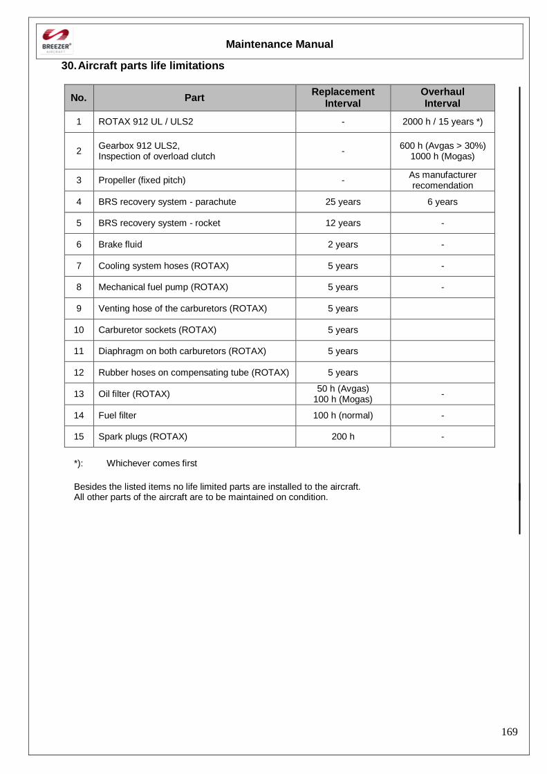
Maintenance Manual
169
30. Aircraft parts life limitations
No. Part Replacement
Interval Overhaul Interval
1 ROTAX 912 UL / ULS2 - 2000 h / 15 years *)
2 Gearbox 912 ULS2, Inspection of overload clutch
- 600 h (Avgas > 30%)
1000 h (Mogas)
3 Propeller (fixed pitch) - As manufacturer recomendation
4 BRS recovery system - parachute 25 years 6 years
5 BRS recovery system - rocket 12 years -
6 Brake fluid 2 years -
7 Cooling system hoses (ROTAX) 5 years -
8 Mechanical fuel pump (ROTAX) 5 years -
9 Venting hose of the carburetors (ROTAX) 5 years
10 Carburetor sockets (ROTAX) 5 years
11 Diaphragm on both carburetors (ROTAX) 5 years
12 Rubber hoses on compensating tube (ROTAX) 5 years
13 Oil filter (ROTAX) 50 h (Avgas)
100 h (Mogas) -
14 Fuel filter 100 h (normal) -
15 Spark plugs (ROTAX) 200 h -
*): Whichever comes first
Besides the listed items no life limited parts are installed to the aircraft. All other parts of the aircraft are to be maintained on condition.