Embed Size (px)
Citation preview

Quality assurance for nonradiographic radiotherapy localizationand positioning systems: Report of Task Group 147
Twyla WilloughbyCo-Chair, Task Group 147, Department of Radiation Physics, M.D. Anderson Orlando, Orlando, Florida32806
Joerg LehmannCo-Chair, Task Group 147, Department of Radiation Oncology, University of California Davis, Sacramento,California 95817
Jose A. BencomoDepartment of Radiation Oncology, US Oncology and Affiliates, Brownsville, Texas 78521
Shirish K. JaniDepartment of Radiation Oncology, Sharp Metropolitan Medical Campus, San Diego, California 92123
Lakshmi SantanamDepartment of Radiation Oncology, Washington University School of Medicine, St. Louis, Missouri 63110
Anil SethiDepartment of Radiation Oncology, Loyola University Medical Center, Maywood, Illinois 60153
Timothy D. SolbergDepartment of Radiation Oncology, University of Texas Southwestern Medical Center, Dallas, Texas 75390
Wolfgang A. TomeDepartment of Human Oncology and Medical Physics, School of Medicine and Public Health,University of Wisconsin, Madison, Wisconsin 53792
Timothy J. WaldronDepartment of Radiation Oncology, University of Iowa, Iowa City, Iowa 52242
(Received 29 September 2011; revised 17 January 2012; accepted for publication 17 January 2012;
published 8 March 2012)
New technologies continue to be developed to improve the practice of radiation therapy. As several
of these technologies have been implemented clinically, the Therapy Committee and the Quality
Assurance and Outcomes Improvement Subcommittee of the American Association of Physicists in
Medicine commissioned Task Group 147 to review the current nonradiographic technologies used
for localization and tracking in radiotherapy. The specific charge of this task group was to make
recommendations about the use of nonradiographic methods of localization, specifically; radiofre-
quency, infrared, laser, and video based patient localization and monitoring systems. The charge of
this task group was to review the current use of these technologies and to write quality assurance
guidelines for the use of these technologies in the clinical setting. Recommendations include testing
of equipment for initial installation as well as ongoing quality assurance. As the equipment
included in this task group continues to evolve, both in the type and sophistication of technology
and in level of integration with treatment devices, some of the details of how one would conduct
such testing will also continue to evolve. This task group, therefore, is focused on providing recom-
mendations on the use of this equipment rather than on the equipment itself, and should be adapta-
ble to each user’s situation in helping develop a comprehensive quality assurance program.VC 2012 American Association of Physicists in Medicine. [DOI: 10.1118/1.3681967]
Key words: quality assurance, localization, optical tracking, radiation therapy, electromagnetic
tracking, infrared cameras, video localization
TABLE OF CONTENTS
I. BACKGROUND . . . . . . . . . . . . . . . . . . . . . . . . . . . . . 1729
I.A. Introduction . . . . . . . . . . . . . . . . . . . . . . . . . . . . . 1729
I.B. Theory of localization and tracking systems. . 1730
I.B.1. Stereoscopic (binocular) imaging . . . . . . 1730
I.B.2. Monoscopic (cyclopedian) imaging . . . . 1731
I.B.3. Radiofrequency tracking . . . . . . . . . . . . . 1731
I.C. Commercially available non-radiographic
localization/tracking systems . . . . . . . . . . . . . . . 1732
I.C.1. Infrared systems [BrainLAB’s
ExacTrac system/Varian free track
(SonArray), Varian RPM] . . . . . . . . . . . . 1732
I.C.2 Optical systems (AlignRT and C-Rad
sentinel) . . . . . . . . . . . . . . . . . . . . . . . . . . . . 1733
1728 Med. Phys. 39 (4), April 2012 0094-2405/2012/39(4)/1728/20/$30.00 VC 2012 Am. Assoc. Phys. Med. 1728
I.C.3. Radiofrequency systems . . . . . . . . . . . . . . 1733I.C.4. Other systems. . . . . . . . . . . . . . . . . . . . . . . 1734
II. SYSTEM SPECIFICATION, SITE
PREPARATION, AND INSTALLATION . . . . . . . 1734
III. ACCEPTANCE TESTING AND
COMMISSIONING. . . . . . . . . . . . . . . . . . . . . . . . . . 1736
III.A. Acceptance testing . . . . . . . . . . . . . . . . . . . . . . 1736
III.B. Commissioning . . . . . . . . . . . . . . . . . . . . . . . . . 1737
III.B.1. Integration of peripheral equipment . . 1738
III.B.1.a. Communication with electronic
medical records systems. . . . . . . . . . . 1738
III.B.1.b. Integration with the linear
accelerator . . . . . . . . . . . . . . . . . . . . . . 1738
III.B.1.c. Determination of the localization
field of view. . . . . . . . . . . . . . . . . . . . . 1739
III.B.2. Spatial reproducibility and drift . . . . . . 1739
III.B.3. Static localization accuracy. . . . . . . . . . 1740
III.B.3.a. Localization displacement accuracy . 1740
III.B.3.b. End-to-end localization assessment . 1740
III.B.4. Dynamic localization accuracy. . . . . . . 1741
III.B.4.a. Spatial accuracy. . . . . . . . . . . . . . . . . . 1741
III.B.4.b. Temporal accuracy (latency) . . . . . . . 1741
III.B.4.c. Dynamic radiation delivery (gating
or tracking) . . . . . . . . . . . . . . . . . . . . . . 1742
III.B.5. Vendor-recommended assessment . . . . 1742
III.B.6. Documentation . . . . . . . . . . . . . . . . . . . . 1742
III.B.7. Standard operating procedures . . . . . . . 1742
IV. CLINICAL USE AND ONGOING QUALITY
ASSURANCE . . . . . . . . . . . . . . . . . . . . . . . . . . . . . . 1742
IV.A. Daily QA. . . . . . . . . . . . . . . . . . . . . . . . . . . . . . 1742
IV.A.1. Safety . . . . . . . . . . . . . . . . . . . . . . . . . . . . 1742
IV.A.2. Static localization. . . . . . . . . . . . . . . . . . 1742
IV.A.3. Documentation . . . . . . . . . . . . . . . . . . . . 1743
IV.A.4. Vendor recommended tests . . . . . . . . . 1743
IV.B. Monthly QA . . . . . . . . . . . . . . . . . . . . . . . . . . . 1743
IV.B.1. Safety . . . . . . . . . . . . . . . . . . . . . . . . . . . . 1743
IV.B.2. Static localization accuracy (hidden
target test) . . . . . . . . . . . . . . . . . . . . . . . . 1743
IV.B.3. Dynamic localization accuracy . . . . . . 1743
IV.B.4. Vendor recommended tests. . . . . . . . . . 1743
IV.B.5. Documentation . . . . . . . . . . . . . . . . . . . . 1743
IV.C. Annual QA . . . . . . . . . . . . . . . . . . . . . . . . . . . . 1743
IV.C.1. System safety . . . . . . . . . . . . . . . . . . . . . 1743
IV.C.2. System integrity . . . . . . . . . . . . . . . . . . . 1743
IV.C.3. Camera stability . . . . . . . . . . . . . . . . . . . 1743
IV.C.4. Extended system performance . . . . . . . 1743
IV.C.5. Positioning accuracy . . . . . . . . . . . . . . . 1743
IV.C.6. Evaluation of gating or tracking
capabilities. . . . . . . . . . . . . . . . . . . . . . . . 1743
IV.C.7. Data transfer . . . . . . . . . . . . . . . . . . . . . . 1744
IV.C.8. Vendor recommended tests. . . . . . . . . . 1744
IV.C.9. Documentation . . . . . . . . . . . . . . . . . . . . 1744
IV.D. Patient specific QA . . . . . . . . . . . . . . . . . . . . . 1744
IV.E. QA in special situations . . . . . . . . . . . . . . . . . 1744
IV.F. Time planning . . . . . . . . . . . . . . . . . . . . . . . . . . 1744
V. CONCLUSIONS/RECOMMENDATIONS . . . . . . 1745
VI. DISCLOSURES. . . . . . . . . . . . . . . . . . . . . . . . . . . . . 1745
I. BACKGROUND
I.A. Introduction
The primary goal of radiation therapy is to deliver a tumorici-
dal dose while minimizing dose-limiting normal tissue effects.
In recent years, advanced technologies such as intensity
modulated radiotherapy (IMRT) and stereotactic body radia-
tion therapy (SBRT) have allowed the delivery of higher
doses to tumors while sparing adjacent radiosensitive struc-
tures. As these approaches are often accompanied by steep
dose gradients, it is essential that the planned dose distribution
be delivered as accurately as possible to maximize the benefit
to the patient. This in turn imposes rigorous attention to accu-
rate patient localization and motion compensation.
In order to improve irradiation accuracy, particularly
when combined with highly conformal delivery techniques,
several different technologies have been developed to image
the patient daily and/or track the patient during treatment.
Image guidance technologies (IGRT) include kilovoltage
(kV) x-rays imaging, in-room computed tomography (CT),
kV and MV cone-beam CT, and ultrasound. Imaging techni-
ques such as these provide the ability to visualize the patient
anatomy and to directly correlate the patient settings to the
initial planned settings. Other technologies that do not use
ionizing radiation have also been developed for the purpose
of patient setup and monitoring, with the clear benefit that
no additional dose is delivered to the patient from the local-
ization procedure. As an added benefit, infrared, optical, and
radiofrequency(RF) based technologies provide real-time
feedback and can be used to monitor motion such as that due
to respiration.
This report reviews concepts, clinical applications, and
quality assurance for patient positioning, localization, and
motion compensation that use nonradiographic technologies
such as video and infrared cameras, surface texture map
imaging, and radiofrequency tracking systems. These tech-
nologies are used for external beam radiation therapy, stereo-
tactic radiation therapy, respiratory gating, and real-time
patient monitoring. While some of these systems make use
of implanted fiducials, the use of radiographic techniques for
localizing these markers is outside of the scope of this report,
which is limited to nonradiographic and nonultrasound sys-
tems. Several other AAPM task group efforts, listed below
for reference, address QA issues associated with image-
guided radiation therapy:
Task Group 104: The Role of In-Room kV X-Ray Imaging
for Patient setup and Target Localization1
Task Group 135: Quality Assurance for Robotic
Radiosurgery2
Task Group 142: Quality assurance of medical accelerators3
Task Group 154: Quality Assurance of Ultrasound-Guided
External beam Radiotherapy for Prostate Cancer4
Task Group 179: Quality Assurance for image-guided radiation
therapy utilizing CT-based technologies (not yet published)
Daily setup variation, interfraction, and intrafraction ana-
tomical changes can create significant uncertainty with
regard to radiotherapy localization. Generally, uncertainty in
1729 Willoughby et al.: Task Group 147: Nonradiographic localization 1729
Medical Physics, Vol. 39, No. 4, April 2012
location of the clinical target volume (CTV) is accounted for
by adding an appropriate margin to create a planning target
volume (PTV).5 Tumors in the abdomen and pelvis tend to
exhibit variability due to organ filling, while targets in the
thorax or in the upper abdomen are most affected by respira-
tory and cardiac motion. Because extending PTV margins to
account for setup and motion uncertainties frequently results
in the irradiation of unacceptably large volumes of healthy
tissue, minimizing uncertainty due to daily setup variation
and inter- and intrafraction motion is highly desirable.
Interfraction motion, or more accurately, interfraction vari-
ation refers to changes in the patient setup from one fraction
to the next. This may include changes in the patient’s anat-
omy, such as variation in organ filling, changes in size of the
tumor, weight changes, and differences in baseline breathing.
There are several clinical approaches to minimizing interfrac-
tion variation. These include image-based techniques, stereo-
scopic x-ray imaging, volumetric (CT) x-ray imaging, and
ultrasound imaging, as well as the nonradiographic methods
covered in this report.6–9 It is important to note that pretreat-
ment image guidance offered by some systems, allows correc-
tion only at specific time points during the patient alignment
process, and in general is not continuous. There have been
many studies that address the effects of interfraction motion
for various different clinical situations.10–14
In contrast, intrafraction motion refers to the motion of
the patient and/or internal organs during delivery of a treat-
ment fraction. A number of authors have investigated inter-
nal organ motion in a variety of tumor sites, including
lung,15 liver,16–18 prostate,19,20 and breast.21–23 These studies
indicate that internal anatomy can move significantly in time
intervals corresponding to the duration of a radiation frac-
tion. Other studies indicate that a tumor volume may deform
or change from one fraction to the next or during a single
fraction.24–26 Recently, several reports have been published
that describe the possible dosimetric impact of such motion
for a variety of anatomical sites.27–38 A summary of the
management of respiratory motion is given in the report of
AAPM Task Group 76.39 The technologies outlined in this
report are specifically designed to provide feedback on intra-
fraction motion during treatment. Systems based on video or
radiofrequency technology typically have a fast update rate
and therefore can be used to track intrafraction changes.
Depending on disease location and individual patient motion
characteristics, surface tracking technologies may or may
not provide a good surrogate for internal motion; surface
tracking has been shown to be a poor surrogate for prostate
motion40,41 and may or may not have an adequate correlation
with targets in the thorax and abdomen, depending on indi-
vidual patient characteristics.
I.B. Theory of localization and tracking systems
The objective of several of the systems outlined in this
report is to provide accurate three-dimensional information
about the patient anatomy from two-dimensional input data
(images). Derivation of 3D information from image data
generally involves the addition of invariant geometry to the
data, through a priori knowledge of the detector geometry
and/or addition of known image features. Cyclopedian or
monoscopic systems use feature-additive methods, whereas
binocular or stereoscopic devices may rely upon the relative
geometry of two sensors in deriving 3D scene information.
This may be combined with other manipulation of illumina-
tion to improve feature identification in the 2D data set.
Photogrammetry is the extraction of three-dimensional in-
formation from data acquired by means of two-dimensional
images.42 The technology has been used for many years in
radiotherapy to obtain surface contours, and now it is being
used to register surface contours.43–46 The current photogram-
metry types used in radiation therapy are based on video or
visible light, infrared, or laser detection.47 The technologies of
the cameras may be different, but the theory of operation falls
in the following three categories based on the geometry of the
systems: Stereo or binocular imaging which uses two cameras
or receivers; Single Camera or cyclopedian/monocular imag-
ing which uses a single camera or imager; or interferometry
which can use either one or two cameras or detectors but relies
on wave interference principals. There are several different
clinical systems that fall in either the binocular or monocular
camera configuration that may use fiducials or patterned light
to aide in signal detection. Since currently no system uses
interferometry in radiation therapy, it is not described.
In all cases, fundamental accuracy of 3D reconstruction
from 2D data is limited by basic detector characteristics.
These include light frequency response, pixel size, lens qual-
ity, and acquisition geometry. It should be noted that
received pixel size and shape are dependent upon the acqui-
sition geometry of a given scene, therefore ultimate resolu-
tion and distortion characteristics of an individual system
will depend upon the geometry of the installed system.
The other major technology that is used in tracking is ra-
diofrequency tracking. This technology uses a transponder
and a receiver. The receiver accepts a signal from the trans-
ponder and is able to triangulate the position of the transpon-
der based on the use of a specific geometry of the
transponders. The theoretical basis of electromagnetic track-
ing is also described.
I.B.1. Stereoscopic (binocular) imaging
When a pair of cameras is arranged such that they view a
common scene in a fixed geometry, it is possible to recon-
struct 3D scene information from the image pair. There are
generally three steps to this process:
1. Identify spatially invariant or known features in the first
image (feature extraction).
2. Locate corresponding features in the second image (fea-
ture correspondence).
3. Compute the 3D coordinates of the features using the tri-
angles formed by the known locations of the cameras and
the intersection of their respective projections into the
common volume of view.
Steps 1 and 2 above can be computationally intensive,
and various developments have resulted in development of
1730 Willoughby et al.: Task Group 147: Nonradiographic localization 1730
Medical Physics, Vol. 39, No. 4, April 2012
different measurement products. The features to be used
must be clearly visible in both images. “Features” in this
context may be native parts of the image scene, or may be
added to the image in the form of fiducials or projected light.
Feature extraction can be accelerated by manipulating illu-
mination and/or through the use of emissive or reflective
fiducials. Some stereoscopic systems, such as Free Track
(Varian Medical Systems, Palo Alto, CA) and Exactrac
(BrainLAB AG, Feldkirchen, Germany) utilize infrared illu-
mination and retroreflective markers to produce very dis-
tinct, high-contrast features in each image that are readily
distinguished from other image content. This permits simple
signal processing algorithms to be used to quickly locate
desired features in each image.
Structured light projection is another means of providing
known features to an image for extraction. Here, a known
pattern of light is projected onto the scene during image ac-
quisition. The structured light pattern in the images then con-
stitutes the features to be extracted. Examples of this form of
photo generation are given in Siebert et al.48 This technology
is employed by VisionRT for use in surface tracking.
Establishing correspondence of features from one image
to the other is usually accomplished through various search
and correlation algorithms. One means of speeding the corre-
spondence process is by taking advantage of the epipolar ge-
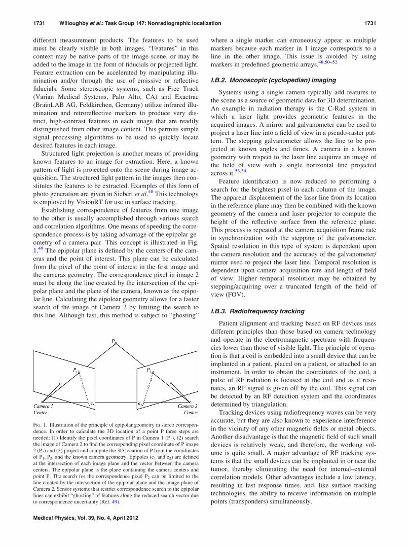
ometry of a camera pair. This concept is illustrated in Fig.
1.49 The epipolar plane is defined by the centers of the cam-
eras and the point of interest. This plane can be calculated
from the pixel of the point of interest in the first image and
the cameras geometry. The correspondence pixel in image 2
must be along the line created by the intersection of the epi-
polar plane and the plane of the camera, known as the epipo-
lar line. Calculating the eipoloar geometry allows for a faster
search of the image of Camera 2 by limiting the search to
this line. Although fast, this method is subject to “ghosting”
where a single marker can erroneously appear as multiple
markers because each marker in 1 image corresponds to a
line in the other image. This issue is avoided by using
markers in predefined geometric arrays.48,50–52
I.B.2. Monoscopic (cyclopedian) imaging
Systems using a single camera typically add features to
the scene as a source of geometric data for 3D determination.
An example in radiation therapy is the C-Rad system in
which a laser light provides geometric features in the
acquired images. A mirror and galvanometer can be used to
project a laser line into a field of view in a pseudo-raster pat-
tern. The stepping galvanometer allows the line to be pro-
jected at known angles and times. A camera in a known
geometry with respect to the laser line acquires an image of
the field of view with a single horizontal line projected
across it.53,54
Feature identification is now reduced to performing a
search for the brightest pixel in each column of the image.
The apparent displacement of the laser line from its location
in the reference plane may then be combined with the known
geometry of the camera and laser projector to compute the
height of the reflective surface from the reference plane.
This process is repeated at the camera acquisition frame rate
in synchronization with the stepping of the galvanometer.
Spatial resolution in this type of system is dependent upon
the camera resolution and the accuracy of the galvanometer/
mirror used to project the laser line. Temporal resolution is
dependent upon camera acquisition rate and length of field
of view. Higher temporal resolution may be obtained by
stepping/acquiring over a truncated length of the field of
view (FOV).
I.B.3. Radiofrequency tracking
Patient alignment and tracking based on RF devices uses
different principles than those based on camera technology
and operate in the electromagnetic spectrum with frequen-
cies lower than those of visible light. The principle of opera-
tion is that a coil is embedded into a small device that can be
implanted in a patient, placed on a patient, or attached to an
instrument. In order to obtain the coordinates of the coil, a
pulse of RF radiation is focused at the coil and as it reso-
nates, an RF signal is given off by the coil. This signal can
be detected by an RF detection system and the coordinates
determined by triangulation.
Tracking devices using radiofrequency waves can be very
accurate, but they are also known to experience interference
in the vicinity of any other magnetic fields or metal objects.
Another disadvantage is that the magnetic field of such small
devices is relatively weak, and therefore, the working vol-
ume is quite small. A major advantage of RF tracking sys-
tems is that the small devices can be implanted in or near the
tumor, thereby eliminating the need for internal–external
correlation models. Other advantages include a low latency,
resulting in fast response times, and, like surface tracking
technologies, the ability to receive information on multiple
points (transponders) simultaneously.
FIG. 1. Illustration of the principle of epipolar geometry in stereo correspon-
dence. In order to calculate the 3D location of a point P three steps are
needed: (1) Identify the pixel coordinates of P in Camera 1 (P1), (2) search
the image of Camera 2 to find the corresponding pixel coordinate of P image
2 (P2) and (3) project and compute the 3D location of P from the coordinates
of P1, P2, and the known camera geometry. Epipoles (e1 and e2) are defined
at the intersection of each image plane and the vector between the camera
centers. The epipolar plane is the plane containing the camera centers and
point P. The search for the correspondence pixel P2 can be limited to the
line created by the intersection of the epipolar plane and the image plane of
Camera 2. Sensor systems that restrict correspondence search to the epipolar
lines can exhibit “ghosting” of features along the reduced search vector due
to correspondence uncertainty (Ref. 49).
1731 Willoughby et al.: Task Group 147: Nonradiographic localization 1731
Medical Physics, Vol. 39, No. 4, April 2012
I.C. Commercially available non-radiographic localiza-tion/tracking systems
Several systems that use the theories and technologies
described above are now commercially available for local-
ization and real-time monitoring and tracking of radiother-
apy patients.55–57 In this section, the specific implementation
and operation of these commercial nonradiographic localiza-
tion technologies is described. In some situations, the com-
mercial systems may be used in combination with
radiographic or ultrasound imaging. In this case, QA of
IGRT systems is addressed elsewhere, notable the reports of
various task groups listed in Sec. I A. Additionally, some
localization systems provide integration with radiation deliv-
ery systems, for example, to gate the treatment beam or track
a tumor using a moving MLC or couch, with the latter two
still being under development.58–62 Physicists must be aware
of how these systems integrate in order to develop a thor-
ough QA program. This report also addresses the QA aspects
of the localization capabilities of the equipment. Dosimetric
quality assurance is discussed in the report of TG 142 and
related documents.
I.C.1. Infrared systems [BrainLAB’s ExacTrac system/Varian free track (SonArray), Varian RPM]
Free Track (Varian Medical Systems, formerly Zmed) is
a stereoscopic optical (infrared) tracking system that allows
submillimeter patient positioning and real-time tracking of
patients during treatment.55,63 The stereoscopic nature comes
from two cameras that focus at targets on the patient or on a
device such as an ultrasound probe. The infrared (IR) track-
ing system has been employed predominately in the treat-
ment of targets within the brain as a complement to
stereotaxy systems.64 This system is minimally invasive and
employs a bite block connected to an optically reflective
plate. The bite block is affixed to the upper palate and maxil-
lary dentition of the patient. It is important to note that the
relevance of the IR tracking to internal cranial and skull-
base targets is a function of the bite block’s stability and
reproducibility. The system consists of two IR-sensitive ster-
eoscopic CCD cameras and is capable of operating using ei-
ther active IR emitters or passive reflectors. Software within
a localization package recognizes the fixed arrangements of
reflectors attached to the patient bite block and their relation-
ship to the planned isocenter. The user console displays the
three translations and three rotations required to align the
patient. An interface to the treatment machine can be used to
terminate the radiation beam based on a selected tolerance
set by the user.63,65–67 Infrared detectors have also been
attached to other equipment in the room to provide localiza-
tion of imaging equipment. This is the case for SonArrayTM
from Varian where the infrared markers are attached to an
ultrasound probe for ultrasound image guidance.
ExacTrac x-ray 6D is a localization system that utilizes
stereoscopic x-rays for image-guided radiation therapy in
combination with an infrared stereoscopic subsystem and a
robotic couch capable of correcting rotations about two axes.
The system can be deployed with all components fully inte-
grated, or with specific components used independently. The
infrared subsystem can be used to localize the patient prior
to imaging, and to monitor the patient’s position during
treatment. The x-ray component is used to determine the
final position, based on either internal anatomy or implanted
markers. The required couch translations and rotations deter-
mined by the imaging component are guided by the infrared
system, based on markers (IR reflectors) attached either to
the couch or to the patient. For the purposes of this report,
only the operation and QA of the infrared components are
discussed. The reader is referred to the reports of Task
Groups 104 and 142 for more information on QA of the x-
ray system.1,3
Another use of infrared cameras is in the management of
respiratory motion (e.g., Exactrac system, Varian RPM sys-
tem) for tumors in the thorax and abdomen.56,68,69 A breath-
ing signal is generated from the infrared camera system by
visualizing the motion of one or more reflectors placed on
the patient surface. This signal is electronically coupled to
the linear accelerator and can be used to facilitate gating.
QA frequency and both geometric and dosimetric tolerances
in phantom-testing scenarios, for beam delivery with gated
radiation are discussed in TG142.3
The Cyberknife system uses three infrared cameras as
well as infrared reflectors for both tracking and for position-
ing. The QA objectives of this report are applicable to the
camera configuration of the Cyberknife system; however,
the camera tracking is not sold as an independent device that
could be added to another system. The reader is referred to
the report of AAPM Task Group 135 for more information
about QA of the Cyberknife system.2
The primary reason camera systems have been successful
is that they require minimal equipment and have a rapid
update rate to facilitate real-time marker tracking. When
properly implemented, these camera systems are also very
accurate for remote patient monitoring. A disadvantage of
infrared camera tracking is that it requires infrared reflectors
to be placed on a device or on the patient. One area of con-
cern in the use of infrared reflectors is that a direct line of
sight between the reflector and the camera must be main-
tained. With other equipment in the room, it is possible for
one or more of the reflectors to be obscured or partially
obscured, which might lead the system to erroneously report
a location. All systems have safeguards for determining
whether a reflector is partially obscured, and for reporting to
the user that the system is unable to track due to a blocked
reflector. Another disadvantage is that infrared light systems
can only address external patient motion, which may be dif-
ferent from the motion of internal organs of interest to the
treatment, as discussed in Sec. I A.
The BrainLAB infrared system and the Varian Optical
Tracking system provides a signal to move the Varian couch
from outside of the room. The Varian RPM and BrainLAB
ExacTrac gating systems can hold the beam if the patient
moves and during gated operation. For both Varian and
BrainLab, the remote motion based on the infrared signal is
FDA cleared. For configurations of Exactrac on other linear
accelerator couches, there is currently no remote couch
1732 Willoughby et al.: Task Group 147: Nonradiographic localization 1732
Medical Physics, Vol. 39, No. 4, April 2012
motion; however, in the future, if an interface to the couch is
provided by the linear accelerator vendor, this could be pos-
sible and should be checked at installation by all vendors
involved and the physicist.
I.C.2 Optical systems (AlignRT and C-Rad sentinel)
AlignRT (Vision RT, London, UK) utilizes real-time 3D
surface imaging techniques in combination with high speed
tracking technology to determine the position of a patient in
three dimensions. AlignRT utilizes stereoscopic video
images in combination with patterns it projects onto the
patient to dynamically capture and reconstruct maps of the
patient’s surface. Two or more camera pods are mounted in
the treatment room and optionally also in the simulation
room. Each pod contains one camera that projects a pattern
on the patient and cameras to image the reflected pattern.
Cameras can acquire single frame or continuous images at a
rate of 7.5 frames/s. Three-Dimentional matching software
is used to align the image captured on the treatment day with
a reference image and to calculate the couch translations
needed to correct a patient’s position. Reference images can
either be generated based on the CT body contour or
obtained with the system when the patient is positioned cor-
rectly. The AlignRT system provides a signal that can be
sent to an interface box or card to move the Linear accelera-
tor couch from outside of the room(depending on Linac ven-
dor and installation configuration). It can also hold the beam
if the patient moves and during gated operation. The system
was reported to be highly stable and to detect predefined
shifts with an accuracy of less than 1 mm and rotational cor-
rection around the vertical axis less than 1� in phantom.50,52
Initial applications of this device have included respiratory-
gated treatment for radiotherapy of breast cancer.70,71 The
system has also been evaluated for respiratory gating in tho-
racic and abdominal tumor sites and in patient alignment for
prostate cancer.50,72 In such applications, the real-time 3D
datasets are matched with corresponding reference images,
obtained in the desired respiratory phase at the time of CT
simulation. Another published application of this system has
been for tracking and aligning the head for high-precision
radiosurgery treatment.73
A limitation of this system is that it only tracks the sur-
face and an additional system may be necessary to determine
correlation between the alignment of the patient and the
alignment of the internal target. Another limitation is that
the cameras are sometimes unable to gather signals on low
reflective surfaces such as hair and clothing. For most
patients, the entire area of interest should be uncovered so
that the skin is exposed. For head and neck or brain patients,
where masks are traditionally used for immobilization, par-
tial masks, which expose significant portions of the face, can
be employed. While such masks are likely less immobiliz-
ing, it has been reported that patient positioning can be
assured through monitoring with the AlignRT system. Also
these masks are more comfortable to the patient.73
The current AlignRT system can be interfaced with some
treatment machines. An interface provided by the linear
accelerator vendor allows the couch translations from the
remote localization system to be sent to the treatment couch
for remote couch control. The correct application of these
translations can then be checked with the AlignRT system.
A gating interface to stop the treatment beam if the patient
moves beyond a set limit, as determined by AlignRT, is also
available, and also sends the signal to an interface provided
by the linear accelerator vendor. For each install, the user
will need to verify with their linear accelerator vendor and
their localization system vendor the availability of such
interfaces, and receive recommendations on installation and
testing.
For localization purposes, 3D scanning lasers can be used
to image the surface of a patient and to compare this surface
with a reference surface. An example of a laser positioning
system is the Sentinel laser alignment system (C-Rad AB,
Uppsala, Sweden, marketed by Acceletronics, Inc Extan,
PA). This device utilizes a laser scanning galvanometer and
a video camera, which are installed in a single ceiling-
mounted package. The scanning laser passes over the
patient’s surface and the apparent deformation of the laser
line is used to render the surface. The patient’s surface posi-
tion is then compared to a reference surface to determine the
patient’s offset.54
This system is FDA approved, but is relatively new and
therefore there are few publications on its clinical use. This
device was reported to be accurate for aligning surfaces and
for surface tracking in moving phantoms.54 A contour from
the CT scan can also be used as a reference surface for align-
ing the patient at the treatment machine. Current limitations
are its limited connectivity with treatment planning systems
and its limited connectivity to the linear accelerator where
calculated alignment shifts may not be able to be automati-
cally employed. Additionally, as this is a surface tracking
system it may not be adequate for targets within the body
unless coupled with a device capable of imaging internal
anatomy.
I.C.3. Radiofrequency systems
Radiofrequency signals have been used in radiology and
surgery for a number of years. These devices typically con-
sist of an RF transponder at the end of a cabled system or an
array of RF detectors (“Flock of Birds”).74–80 These devices
have traditionally been limited to either surface detection or
have been used to track instruments inserted into the body
such as the SuperDimension RF guided bronchoscopy device
(SuperDimension, Inc., Minneapolis, MN), or the MicroPos
system (Micropos Medical AB, Gothenburg, Sweden) that is
designed to place an RF device into a catheter that is left in
place during a radiation procedure.
The Calypso 4D localization system (Calypso Medical
Technologies, Seattle, WA) utilizes radiofrequency signals
for wireless localization and tumor tracking during radiation
therapy. It is currently approved by the FDA for use in pros-
tate or post prostatectomy radiotherapy. The system operates
by detecting alternating current (AC) from electromagnetic
markers (BeaconTM) or transponders. The transponders are
1733 Willoughby et al.: Task Group 147: Nonradiographic localization 1733
Medical Physics, Vol. 39, No. 4, April 2012
approximately 8 mm in length and 2 mm in diameter, and
consist of an AC electromagnetic resonance circuit encapsu-
lated in glass. They are inserted into the prostate gland or
prostatic bed under ultrasound guidance similar to a needle
biopsy. For other body applications under investigation, the
transponders can also be inserted into other areas of interest,
or alternatively attached to the surface of or to other devices
used in radiotherapy such as a bite block.
An array of source coils positioned a short distance above
the patient produces an oscillating electromagnetic field.
Energy from this field induces a resonance inside the trans-
ponder circuit, and the decay of the resonant signal is detected
by a second array of receiver coils. Both the source and detec-
tion coils are mounted within the same panel, which is
coupled to a console inside the treatment room. Typically,
three different transponders, each with different resonating
frequencies, are used; therefore, the signal emanating from
each transponder can be uniquely localized by triangulation.
The beacons’ coordinates and the plan isocenter are initially
identified on a treatment planning CT, and the offset between
the planned isocenter and the intended isocenter is reported by
the localization system at a frequency of 10 Hz.
The Calypso console, which contains the in-room controls
and has an arm to suspend the panel over the patient, is posi-
tioned near the treatment couch and locked into place. Three
infrared cameras mounted on the ceiling of the treatment
room track infrared markers on the panel surface. The loca-
tion of the panel relative to the linac isocenter is defined
through a calibration procedure. Therefore, the position of
the transponders relative to the panel and the position of the
panel relative to the isocenter are known at all times. The
panel is left in place during irradiation and its radiation
attenuation has been reported to be negligible, but should be
verified by the user.81 Through a graphical user interface in
the treatment machine control area, the Calypso system dis-
plays real-time graphs instantaneously highlighting shifts in
position that exceed a user-specified threshold. Interface
modules with radiation delivery system to shut off the beam
if the target moves outside of user-specified parameters as
well as to transfer couch shift values to the treatment
machine are available. Several studies have described in
detail the clinical use of this system as well as the sub milli-
meter localization accuracy that can be achieved when
employing these systems for real-time intrafraction patient
and/or organ motion tracking.33,56,82,83
Another RF based localization device is RayPilot (Micro-
pos Medical AB, Gothenburg, Sweden). At this time it is
undergoing testing and is not FDA cleared in the U.S. This
system is a wired device and uses a catheter, surgically
implanted in the prostate, as a conduit for an RF transmitter.
The patient is placed on a special couch top plate that powers
the RF transponder and can detect the location of the device
within the patient in real-time.84
A potential issue with any implanted markers, such as
those used with RF based systems, is marker migration away
from their locations at simulation. The Calypso system miti-
gates the issue by assessing the position of multiple markers
relative to each other.82
Another limitation is the relatively small field of view or
operating range (in the case of Calypso, approximately 20
cm), thus use in very large patients is a contraindication for
the Calypso system. Finally, the Calypso panel must be posi-
tioned prior to each treatment, which requires additional
setup time.
On September 19, 2011, Varian Medical Systems, Inc.,
and Calypso Medical Technologies, Inc., announced they
signed a definitive agreement under which Varian will ac-
quire Calypso.
As with the infrared and video systems, integrations
between a radiofrequency tracking system and the linear ac-
celerator for remote motion or for gating control will rely on
the linear accelerator vendor for both the couch control inter-
face and the linac beam control interface. The user should
check with both the linear accelerator vendor and the local-
ization vendor to determine if such an interface exists and to
receive appropriate testing for such an interface.
I.C.4. Other systems
A list of all FDA cleared and commercially available sys-
tems available at the time of this writing is provided in Table
I. These systems follow the principles outlined in this report
and are briefly described above. The remaining sections will
outline QA principles that are common to all nonradio-
graphic systems that are used for localization. While
attempts have been made to cover all technologies that can
be used for localization and tracking, it is foreseeable that
additional nonradiographic localization devices may be
available in the near future. One such device is the Navotek
system that uses an implanted radioactive marker in combi-
nation with an add-on radiation detector/localization device
for tracking the implanted marker. Several publications
describe the device and its use in prostate localization.85–87
While no specific descriptions about future products can
be given at this date, the basic principles of quality assurance
for nonradiographic localization and positioning systems as
described in the report should be applicable to other localiza-
tion devices.
II. SYSTEM SPECIFICATION, SITE PREPARATION,AND INSTALLATION
An essential feature of the devices discussed above is that
they are compatible with the treatment delivery process. For
such systems, it is important for the radiation therapy team
to determine how and why the equipment will be used both
for clinical and research purposes prior to the purchase so
that appropriate specifications, installation, and quality
assurance processes can be developed. This team should be
lead by a designated qualified medical physicist (QMP).
Most add-on localization systems are calibrated to isocen-
ter by using the room lasers as the reference system. The ac-
curacy of the add-on localization system is therefore
dependent upon the accuracy of the in-room laser localization
system. It is important that the specification, purchase, and in-
stallation process include an a priori evaluation and definition
of the room reference coordinate system (i.e., in-room lasers
1734 Willoughby et al.: Task Group 147: Nonradiographic localization 1734
Medical Physics, Vol. 39, No. 4, April 2012
and machine isocenter), which should be done under the
supervision of a physicist similar to the process of acceptance
testing a linear accelerator. The combined patient setup accu-
racy should conform to the recommendations of TG142 of 1
mm for SRS and SBRT and within 2 mm for conventional
treatments. For older linear accelerators, it may be necessary
to arrange with a machine service engineer or consultant to
modify the linear accelerator such that the isocenter meets the
desired goal and to align the lasers per desired specifications
prior to installation of the add-on localization system. If the
isocenter cannot be made to meet the specification, the goals
of the purchase of the add-on localization system should be
reconsidered.
An important installation-specific issue for systems utiliz-
ing room mounted cameras is the mounting stability of any
in-room equipment, which may require fabrication and
mounting by third party contractors. Temperature may play
an important role because thermal expansion and contraction
can affect the mounting hardware and cause a drift of the
system’s identification of the machine isocenter. Similar
problems can arise from natural disasters such as earth-
quakes or other stresses on the building. Architects, engi-
neers, and vendor representatives must coordinate with the
radiation oncology team so that the required modifications
are achieved without interference with other facility or treat-
ment services. This team typically manages compliance with
construction and safety codes, but additional consideration
may be necessary to fulfill local building and safety require-
ments. It is appropriate for the physicist to evaluate the
installation documents to be certain that no parts of the non-
radiographic localization system will interfere with radiation
delivery or shielding. Individuals from the institution’s
facilities management/physical plant group will also need to
verify that proposed installation is compliant with other elec-
trical, emergency, and safety regulations.
If the localization system includes an electronic interface
to the treatment machine, for example, for remote couch con-
trol, radiation gating, radiation tracking, or other capabilities,
it is necessary to establish compatibility of both systems and
to verify correct performance. The add-on localization system
and the radiation delivery machine may not interface directly,
but may communicate via the facility’s record and verify
(R&V) system or other third party interface. This may require
support from the R&V vendors and should be considered in
the planning process and for purchase. The localization sys-
tems will ultimately determine treatment parameters, such as
couch position; quality assurance procedures should include
documentation of these parameters. Prior to clinical use, a
process describing the clinical use of the localization system
should be developed. For example, R&V tolerance tables for
couch parameters may be changed by use of the localization
system. For all connections of the localization device to the
linac or to other computer systems, the physicist should work
with the vendors of the localization device, the linac, and any
other involved system vendors, along with department or hos-
pital IT personnel, to establish these connections following
their guidelines and to ensure that adding the localization
equipment will not violate any service contract.
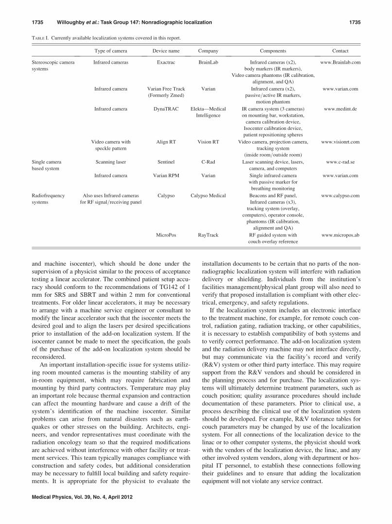
TABLE I. Currently available localization systems covered in this report.
Type of camera Device name Company Components Contact
Stereoscopic camera
systems
Infrared cameras Exactrac BrainLab Infrared cameras (x2),
body markers (IR markers),
Video camera phantoms (IR calibration,
alignment, and QA)
www.Brainlab.com
Infrared camera Varian Free Track
(Formerly Zmed)
Varian Infrared camera (x2),
passive=active IR markers,
motion phantom
www.varian.com
Infrared camera DynaTRAC Elekta—Medical
Intelligence
IR camera system (3 cameras)
on mounting bar, workstation,
camera calibration device,
Isocenter calibration device,
patient repositioning spheres
www.medint.de
Video camera with
speckle pattern
Align RT Vision RT Video camera, projection camera,
tracking system
(inside room=outside room)
www.visionrt.com
Single camera
based system
Scanning laser Sentinel C-Rad Laser scanning device, lasers,
camera, and computers
www.c-rad.se
Infrared camera Varian RPM Varian Single infrared camera
with passive marker for
breathing monitoring
www.varian.com
Radiofrequency
systems
Also uses Infrared cameras
for RF signal=receiving panel
Calypso Calypso Medical Beacons and RF panel,
Infrared cameras (x3),
tracking system (overlay,
computers), operator console,
phantoms (IR calibration,
alignment and QA)
www.calypso.com
MicroPos RayTrack RF guided system with
couch overlay reference
www.micropos.ab
1735 Willoughby et al.: Task Group 147: Nonradiographic localization 1735
Medical Physics, Vol. 39, No. 4, April 2012
Because patient specific information is required for add-
on localization systems, it may be necessary for the system
to access the local area network. It is essential that informa-
tion systems specialists at the facility be involved to ensure
that the proper outlets, data ports, servers, and network secu-
rity (e.g., firewall) are available prior to installation. As part
of systems’ communications, a conformance statement from
the vendor should be provided to assist in setting up mecha-
nisms for data transfer between the localization system,
imaging devices (e.g., CT), treatment planning, and record
and verify systems. Finally, systems should provide a mech-
anism for archive and retrieval of patient data. Ideally, all
data should be transferred to a central electronic record for
permanent storage. Additional safeguards for the use of com-
puters that are to be used for patient alignment should be
managed through the facility’s information technology
department to insure that they are well-protected against the
threat of virus or malware using antivirus software and if
possible all USB ports be secured and internet access limited
to further minimize the risk.
One other area of concern when preparing installation of
add-on equipment is to negotiate a schedule for training. As
new technologies are implemented into a clinical setting, it
is often difficult to have staff stop treating patients to attend
training; however, it is extremely important that all members
of the staff who may use the equipment are fully trained on
the proper equipment operation and possible clinical situa-
tions. This training should include a discussion of clinical
support where the vendor may be consulted and provide
follow-up training sessions for advanced techniques. Specific
areas of training and documentation that are necessary
include (1) proper startup/shutdown of equipment, (2) cali-
bration of equipment, (3) operating procedures, (4) QA pro-
cedures, (5) possible failure modes of the equipment, and (6)
possible failure modes of the localization process using this
equipment.
III. ACCEPTANCE TESTING AND COMMISSIONING
As with all equipment that is used clinically, it is impor-
tant to perform a thorough evaluation both with regard to the
individual components of the new equipment and to the
impact of its use within the overall practice of patient care.
There are many different types of components and equip-
ment that can be used for nonradiographic localization, thus
each user may need to adapt specific tests as necessary based
on their equipment and their unique clinical use. While ven-
dor specific tests typically focus on operation, this report
focuses on application and QA.
It is important to note that with all of the systems described
in this report, system tolerance is often specified as the accu-
racy of the system in matching treatment and machine isocen-
ter. Claims of submillimeter accuracy, while representative of
phantom studies, do not fully describe all sources of uncer-
tainties encountered in clinical practice. Other uncertainties
present in the treatment process, including imaging and calcu-
lation errors, must be included in consideration of the overall
patient treatment and localization accuracy.88
The common link between all of the devices covered in
this task group report is that they are referenced to the
machine radiation isocenter. As already mentioned in the
preinstallation section, it is recommended that the physicist,
along with in-house or field service engineers responsible for
the radiation equipment, verify the tolerance for the treat-
ment machine isocenter, including both measurements of
mechanical isocenter and radiation isocenter, their coinci-
dence, as well as the laser alignment to radiation isocenter.
Proper documentation of the machine isocenter should
include star shot films for collimator, couch, and gantry run
out, and/or results of a “Winston-Lutz” type test, in which
beams-eye images of a ball placed at isocenter are analyzed
as a function of gantry, couch and collimator angle.89 The
accuracy of couch readouts should also be consistent with
the criteria in TG142, dependent upon the procedures in
which the equipment will be used. For standard treatment,
accuracy should be 2 mm and for SBRT or SRS treatments
accuracy within should be within 1 mm. These indicators are
important, as they will be used when verifying the accuracy
for localization using the add-on localization equipment.
Recommendations: The accuracy of the machine iso-center should be checked in accordance with TG-40, TG-142 and the user’s acceptance test documents for their spe-cific linear accelerator. Additionally, if lasers, light field,couch digital readouts, or any other machine componentsare used to define the reference of a peripheral localizationdevice with regard to the linear accelerator, this shall beestablished before installation and checked at minimum atthe frequency recommended by TG142 and more often ifdeemed necessary by the QMP for accurate use of a spe-cific localization device.
III.A. Acceptance testing
For most new equipment, the vendor will provide the user
with an acceptance procedure that will define operation and
limitations of the equipment. It is important to keep in mind
that acceptance tests demonstrate only that the equipment is
working as per the specific purchase contract between the fa-
cility and the vendor. As stated in Sec. II, the radiation ther-
apy team, lead by the physicist, and the vendor should agree
upon a set of acceptance tests prior to purchase so that this
process will adequately illustrate the device works as antici-
pated. In some cases, the acceptance test document is specifi-
cally a vendor document and may not be adapted. In these
situations, it is recommended that the physicist be familiar
with the various tests recommended in the commissioning
section of this report and negotiate for support from the ven-
dor in conducting part of the commissioning if the accep-
tance does not cover these. This also applies to situations
where the vendor does not provide an acceptance procedure
at all or a rudimentary procedure that only insufficiently
demonstrates the needed capabilities of the system.
The acceptance test process should include tests to illus-
trate the safe operation of the localization system along with
basic localization accuracy. Localization accuracy describes
the ability of the system to position a target point at the
1736 Willoughby et al.: Task Group 147: Nonradiographic localization 1736
Medical Physics, Vol. 39, No. 4, April 2012
radiation isocenter. Accuracy evaluation should be custom-
ized to the type of treatments that are desired. For example,
for SBRT treatments, the localization device should be capa-
ble of positioning a point within a phantom to within 1 mm of
the radiation isocenter. Reproducibility is measured in terms
of the standard deviation for repeated localizations. Three or
more measurements are necessary to assess reproducibility.
Some localization systems, particularly those that provide
gated treatment, integrate with the beam delivery of the lin-
ear accelerator. In these cases, it is important that the safety
features and interlocks of the linear accelerator are not com-
promised. The physicist should utilize the acceptance test to
become more familiar with the equipment operation and
should be familiar with the vendor supplied user manual,
which should indicate possible warning messages and safe
use of their equipment. The use of these manuals along with
discussions with the vendor and the installation team can be
useful to help to develop the QA process for additional tests
specific to the users situation that are necessary to prevent
any misuse of the equipment or failures in the equipment
that may not be detected in the machine specific QA that is
outlined in this report.
Additional tests include testing compatibility with other
equipment. This includes communication between the local-
ization device and treatment planning systems, the record
and verify system and the linear accelerator. The vendor
should provide guidelines for basic communications testing.
More details regarding testing of coordinate systems are
included in the commissioning test descriptions in the Sec.
III B. The other major component for compatibility is to
determine the workspace issues for the add-on equipment,
and if there is potential for collisions or limitations of use
under certain circumstances (such as a camera blocked at
some gantry angles.) This also is referred to as limit testing
and is further described in the commissioning test section.
Finally, for each device, the manufacturer is required by
the FDA (or other regulatory agencies if outside of the U.S.)
to provide written documents on adequate direction for safe
use of the equipment. The physicist should be aware of the
possible hazards as well as safety features of the equipment
prior to commencing with commissioning. Safety features
may include automatic shut off, collision detection equip-
ment, and the availability of backup power systems for data
recovery. The physicist should also use the list of possible
equipment or process failure modes compiled during the ac-
ceptance test process to develop additional procedures to
ensure the safety of the patient as well as of the radiation
team. Specific examples of safety hazards with the use of
these peripheral devices are collisions due to add-on equip-
ment, electrical hazards, trip or other mechanical hazards
due to added cabling and wiring. Most of these hazards will
be installation-specific and will not be applicable to each
user; therefore it is important to work with the facilities
department at each institution as well as the vendor to deter-
mine the hazards and to address any possible concerns.
Recommendations: Acceptance testing should evaluatethe localization capabilities and should include some quan-tifiable measure of the localization accuracy and reprodu-
cibility following vendor guideline or those described inSec. III B. The vendor must be able to demonstrate local-ization consistent with the recommendations of TG 142,within 2 mm for conventional delivery and within 1 mm forSBRT or SRS treatments. Safe operation of the equipmentmust also be demonstrated. Proper functionality of thelocalization system interface to the linear accelerator andother computer equipment should be demonstrated. Thevendor and physicist should work together to develop a listof possible failure modes and ongoing system checks andmaintenance as these can be machine and facility depend-ent and can also depend on the specific version of the soft-ware and or hardware that is installed.
III.B. Commissioning
The commissioning of a localization system requires the
radiation oncology team, lead by a designated QMP, to
determine all parameters necessary to utilize the equipment
in a clinical situation. This includes measuring the system
accuracy, determining system limitations, and developing
operating procedures and QA schedules. Some of these tests
will be completed as part of the acceptance test with the ven-
dor; however, in most cases, the acceptance test is at the dis-
cretion of the vendor and may not satisfy all clinical
recommended quality assurance. For example, with respect
to communications, the vendor may only agree to test basic
communications between their system and the other com-
puter systems within the department while this task group
recommends testing various patient configurations (prone/
supine) and data transfer combinations as part of the com-
missioning. Commissioning of the localization system
should include evaluation of the following:
1. Integration of Peripheral Equipment
a. Communication with Record and Verify Systems
b. Integration with the Linear Accelerator
c. Determination of localization Field of View
2. Spatial Reproducibility and Drift
3. Static Localization Accuracy
a. Localization Displacement Accuracy
b. End-to-End Assessment
4. Dynamic Localization Accuracy
a. Spatial Accuracy
b. Temporal Accuracy
c. Dynamic Radiation Delivery (gating/tracking)
5. Vendor-Recommended Assessment
6. Documentation
7. Standard Operating Procedures
The radiation oncology staff should feel comfortable
requesting vendor guidance and participation in conducting
these tests and in requesting that other tests, deemed neces-
sary for safe and effective use, be added to the acceptance
tests. Vendors should provide technical assistance and par-
ticipation in response to reasonable requests.
1737 Willoughby et al.: Task Group 147: Nonradiographic localization 1737
Medical Physics, Vol. 39, No. 4, April 2012
Description of tests: Since all tests of equipment should
be performed at the time of the commissioning of the sys-
tem, the detailed descriptions of the tests are outlined in this
section. Section IV lists the tests that the task group recom-
mends for ongoing daily, monthly, and annual QA but the
reader is referenced back to Sec. III for the description and
design of these tests.
III.B.1. Integration of peripheral equipment
Testing of equipment compatibility in an integrated, mul-
tivendor environment is essential. This section will discuss
the software integration and hardware integration separately.
III.B.1.a. Communication with electronic medicalrecords systems. The peripheral devices described in this
report employ a database to store patient information. This
typically includes patient name, plan information, and either
a scan of the patient surface or the location of internal or
external fiducials and their coordinates relative to the isocen-
ter. Direct communication between the treatment planning
system and the peripheral system, if available, can avoid
transcription errors. Not every system allows direct DICOM
transfer of the localization data from the treatment planning
system or simulation. Some systems communicate using the
record and verify system as a link between the treatment
planning system, the localization system, and the treatment
delivery device. Whether the data entry is manual, via
DICOM transfer, or by some other electronic means, the
radiation team, upon commissioning, must confirm the cor-
rect orientation and spatial geometry of the data. This is par-
ticularly important given that a standard convention for
coordinate systems has yet to be developed. When establish-
ing a link between different systems, each aspect of the data
transfer should be checked individually for data integrity as
described below.
Phantom tests covering a representative variety of clinical
scenarios should be performed to verify relationship/transfor-
mation between different coordinate systems. This may
involve the use of vendor-provided phantoms, but in many
cases these can be inadequate, and the physicist may need to
adapt existing phantoms. This is performed by acquiring CT
images of a phantom in different treatment positions and
selecting a representative target within the phantom (i.e., iso-
center) and applying other superficial marks on the outside of
the phantom at those coordinates. The coordinates for the
phantom and the representative isocenter can be transferred to
the localization system to ensure that the coordinates of the
representative target and the superficial marks represent the
correct location of the phantom relative to the room isocenter.
Different patient orientations would include CT scans with
the phantom identified as headfirst supine, headfirst prone as
well as feet first supine or any other orientation that may be
used clinically. If necessary, markers can be added to a spe-
cific location on the phantom to indicate orientation (for
example, superior, anterior, right side). Also, some systems
use units of cm while others use units of mm; this should be
checked by looking at relative distances between multiple
points or isocenters in a phantom. It is common for treatment
planning systems to use coordinates of the CT scanner, which
may differ from the coordinates of the treatment machine. For
example, in CT coordinates, the Z dimension is typically
aligned with the couch movement or the patient’s superior/in-
ferior axis, which at treatment machine corresponds to the
movement direction of the Y jaws (assuming the collimator in
neutral position) and is typically labeled as such. This testing
should be done whenever the localization system, simulator,
or the R&V system is upgraded, as any of these could lead to
a change in coordinate systems.
III.B.1.b. Integration with the linear accelerator. It is of
utmost importance that any add-on localization equipment
does not adversely affect radiation delivery by attenuating
the radiation beam or by any other means. Any potential
changes in the delivered radiation must be measured. This
includes, but is not limited to, add-on couch tops, immobili-
zation devices, and any other device that may attenuate or al-
ter the beam. For example when using the Calypso system
there is a specific couch top in place, the attenuation through
which may be different than the standard couch top. AAPM
task group 176 (in preparation) is charged with a thorough
analysis of the impact of these devices.
In addition to physical components, there is remote possi-
bility that electronic devices used in the add-on localization
systems could interfere with components within the linear
accelerator. It is important for the physicist to discuss this
with the accelerator vendor, and as always, properly evaluate
the radiation delivery system after any service. Also, if the
system is not used as recommended, by the vendor, the user
should evaluate if specific protocols for off-label use need to
be in place. Generally, the Institutional Review Board (IRB)
should be consulted on any required forms and processes, as
these tend to vary greatly between institutions. Guidance on
off-label use can be found in the report of the AAPM Task
Group 121.90
The radiation team should also be aware of potential
issues that could arise when multiple combinations of add-
on equipment are used in the same treatment room, such as
an add-on MLC, robotic couch tops, and other localization
systems. This may require the support of several different
vendors in order to verify that all add-on equipment combi-
nations have been tested together, and if not, to get the help
of the vendors to design tests to be performed to insure all
equipment will work together.
Radiation delivery with the add-on localization equip-
ment or combinations of added equipment should include
operating both the linear accelerator and the localization
equipment with radiation measurement equipment in place
(phantoms/films) to ensure that the radiation delivery system
operates without triggering machine interlocks and delivers
the prescribed dose. This should also include testing that in
the event the radiation is terminated due to the localization
system (either manually or automatically), that the radiation
is carried out as intended when the beam is resumed. This
test should be performed using representative delivery tech-
niques for patients (i.e., arc, IMRT, static field, or gating).
In some instances, there may be a possibility of the radia-
tion or linear accelerator interfering with the localization
1738 Willoughby et al.: Task Group 147: Nonradiographic localization 1738
Medical Physics, Vol. 39, No. 4, April 2012
equipment. For example, for video based systems, some
cameras may be blocked when certain gantry or couch
angles are used. Partial obstruction of an infrared marker
may cause the system to report a location different than the
true location. For RF localization systems, magnetic or me-
tallic objects, especially oscillating ones such as a motor, in
the treatment room may add radiofrequency noise that intro-
duces error into the localization system. Additionally, use of
an add-on microMLC for stereotactic procedures may create
a situation where MLC motors are closer to the RF detection
equipment than originally measured, causing a similar issue.
To evaluate possible interference or obstructions, one should
plan to deliver several different plans to a phantom while
using the localization system to test both the radiation deliv-
ery and localization system under different combinations of
gantry, couch, and MLC settings. This is to ensure that the
equipment does not interfere with each other and to identify
operating limits and possible collision areas. The process
should be repeated anytime a new treatment technique using
the equipment is introduced in the clinic. Essentially, every
piece of localization equipment that is introduced for patient
treatments should undergo a complete end-to-end test
(described in Sec. III B 3 b) to ensure that a problem is not
overlooked.
In addition it needs to be considered that over longer pe-
riod of exposure to ionizing radiation in the treatment room,
accumulated radiation damage can eventually affect the per-
formance of the localization system. This applies in particu-
lar if the treatment room is for total body irradiation and or
total skin irradiation. These procedures can produce signifi-
cant scattered or direct radiation to these devices, as well as
neutrons from photon beams with energies greater than 10
MV.
III.B.1.c. Determination of the localization field ofview. Most localization systems will have a finite field of
view around the isocenter within which the system can per-
form. Some limitations are due to the detection device range
or the arrangement of the cameras in the room. It is essential
that the radiation team is familiar with this field of view so
that they know how much motion can be detected or possible
scenarios when the accuracy may be compromised or the
localization system may not work. Field of view limitations
may limit the use of the system to only certain couch and gan-
try angle combinations. System descriptions will generally
include information on the localization space. Measurements
to determine the area where the localization system will work
should be performed to verify the manufacturer provided data.
This can be done by moving a phantom from the isocenter
while the localization system is on to determine the distance
from isocenter at which the localization system fails to detect
the phantom. After localizing a phantom, the couch can be
rotated about the isocenter and the gantry rotated to different
angles to determine if the field of view will allow use at vari-
ous different treatment scenarios. Clinical workflows using
localization systems usually require the therapist to set the
patient as close to isocenter as possible using conventional
methods while using the localization system to make minor
adjustments and/or track the patient position.
Recommendations: It is recommended that initialchecks of data transfer include transfer of data from thesimulation, treatment planning and record and verify sys-tem in different patient orientations (head first, feet first,prone, supine, etc.). Both input and output data transfershould work as expected (i.e., coordinates, units and axistransfer to the correct coordinates, units, and axis). Phan-tom delivery of representative patient treatment plansshould be performed to radiation measurement equipmentwith and without the localization system turned on to verifythat the localization device does not change the radiationdelivery (within 1% dose) and radiation does not changethe localization (within 1 mm). The localization field ofview should be measured and documented.
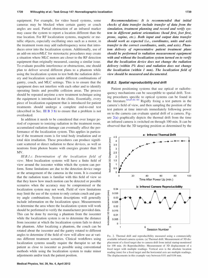
III.B.2. Spatial reproducibility and drift
Patient positioning systems that use optical or radiofre-
quency mechanisms can be susceptible to spatial drift. Test-
ing procedures specific to optical systems can be found in
the literature.63,67,91–93 Rigidly fixing a test pattern in the
camera’s field of view, and then sampling the position of the
test pattern at time intervals immediately following power
on to the camera can evaluate spatial drift of a camera. Fig-
ure 2(a) graphically depicts the thermal drift from the time
an infrared camera is switched on through 100 min. It can be
observed that the 3D targeting position as determined by the
FIG. 2. Thermal drift and reproducibility measured using a commercially
available infrared camera system. (a) Thermal drift: Measurement of 3D dis-
placement of a fixed target due to camera drift from initial startup monitored
for 100 min. (b) Reproducibility: Measurement of 3D displacement of a
fixed target with multiple readings. Vertical axis is the absolute location
reading (mm) for a fixed target and the horizontal axis are multiple readings.
The displacements in this example vary between 0.01 and 0.04 mm.
1739 Willoughby et al.: Task Group 147: Nonradiographic localization 1739
Medical Physics, Vol. 39, No. 4, April 2012
camera system drifts more than 4 mm over the first 80 min.
If the system is calibrated to the radiation isocenter during
this warm-up period the accuracy of the overall system will
be affected. Neither camera calibration nor clinical use
should be performed unless power has been supplied to the
camera for a minimum of 90 min. Some systems have an
interlock or a warning to prevent the use of this system in
this warm-up period; however, this is not true for all sys-
tems, so it is important to add a warm-up time to the proce-
dures for use of systems that demonstrate a thermal drift.
After this initial system warm-up, the reproducibility of
the system can be evaluated by continuing to sample the
position of the test pattern or phantom at fixed temporal
intervals. Figure 2(b) shows the results of repeat measure-
ments taken at 10-min intervals after the camera has stabi-
lized. The duration and magnitude of this initial instability is
camera dependent and should be tested independently at
each site prior to clinical use.
Recommendation: Building on the corresponding testsduring acceptance, stability testing should be performedduring commissioning of a localization system by monitor-ing and recording a test pattern device at initial startup ofthe equipment for at least 90 min or until sufficient stabilityis achieved. Safeguards or procedures should be developedto prevent use during this time. Reproducibility can bemeasured by monitoring this same device for an additional60 min after establishing stability. This test should be doneat least annually or after equipment changes or per manu-facturer specifications.
III.B.3. Static localization accuracy
III.B.3.a. Localization displacement accuracy. The
localization displacement accuracy of any localization sys-
tem needs to be checked over a range that covers all clinical
shifts to be expected for the system. When assessing this
range it should be considered that it is sometimes necessary
to treat multiple target areas, or to align to different locations
than isocenter to check patient setup.
Couch readout QA should have already been performed
following TG142 guidelines so that couch indicators can be
used to compare the shifts that are applied while using the
add-on localization system. If the couch readouts are not
accurate enough for use in testing the localization system
they should either be brought to within tighter specifica-
tions or an accurate motion phantom may be necessary for
this test. The phantom should be positioned at a fixed dis-
tance away from the isocenter and then shifted back to iso-
center using the localization system. The offsets that are
checked should cover a reasonable clinical range. For
example shifting a breast patient from the breast tangents to
the supraclavicular isocenter could be about 10 cm, while
other patients may almost always be aligned to isocenter
within 3 cm. If possible, our recommendation is that at least
10 cm shifts from isocenter or between two isocenters be
checked in all directions. To verify the accuracy of the
couch shift to position a target, orthogonal MV portal veri-
fication images should be taken of a known target within
the localizer phantom. This is similar to the localization
test but includes the accuracy of the couch motion to the
treatment isocenter.
Some systems have the ability to detect and correct for
both rotational and translational deviations. Testing of rota-
tional compensations should be performed if this will be
used on patients. Robotic couchtops can usually be adjusted
to specific angle of pitch, roll, and yaw and these values
should be verified with a digital level. If this type of couch-
top is going to be used for treatment it can be used to intro-
duce different angles to a static phantom in order to test the
localization system ability to detect and correct for the angle
corrections. A phantom that is on a platform with angle cor-
rections could also be used. For devices such as Calypso that
only use a few points, an angle correction could be simulated
by moving one of the three transponders within a phantom
(to known geometry). Currently, most centers do not apply
angle corrections using a 6D couch, however, angle detec-
tion in localization is helpful in indicating if the patient is
rotated in one or more dimensions on the couch and should
be repositioned and relocalized.
III.B.3.b. End-to-end localization assessment. After sys-
tem characteristics have been evaluated, commissioning tests
should focus on the localization system accuracy. Overall
system accuracy is best measured using an end-to-end target
test. For this test a phantom that has embedded radiographic
markers visible on both CT and kV or MV imaging is typi-
cally used. Several commercial phantoms exist for this pur-
pose, and it is also possible to modify existing
anthropomorphic phantoms, or plastic slabs for this purpose.
For surface tracking systems, some plastics may not be usa-
ble due to their reflective properties. Soft plastic mannequins
can be used and phantoms with appropriate surface coloring
to approximate a patient should also work. Some commercial
localization systems may come with a phantom that can be
used to evaluate the entire localization process. To perform
the test, the phantom may be marked with some exterior vis-
ual cues for initial setup. A treatment planning CT scan is
performed under similar conditions as for patients. For local-
ization systems that use specific points identified in the CT
image, the targeting uncertainties are directly related to the
CT slice thickness and field of view, so a high resolution
(small slice spacing< 2 mm) CT with a small field of view
should be used to determine the coordinates of markers and
the isocenter for the phantom. The procedure should also be
performed using the CT protocols that will be used clinically
to compare the localization accuracy under clinical condi-
tions. This may show that the clinical procedure will require
a small slice thickness CT scan through the area of interest
in order to achieve the level of accuracy required for a par-
ticular treatment. The CT scan is then sent to the treatment
planning system where an isocenter can be defined relative
to the location of the hidden target. At the treatment
machine, the phantom is positioned arbitrarily relative to the
isocenter but within the operating range of the imaging sys-
tem to be tested. Using the nonradiographic localization sys-
tem in the treatment room, the couch is moved to restore the
hidden target to the isocenter or to its planned location rela-
tive to isocenter. At this point, orthogonal MV verification
1740 Willoughby et al.: Task Group 147: Nonradiographic localization 1740
Medical Physics, Vol. 39, No. 4, April 2012
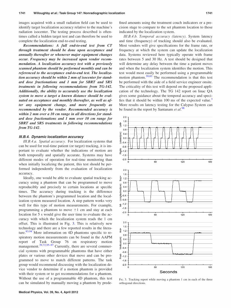
images acquired with a small radiation field can be used to
identify target localization accuracy relative to the machine’s
radiation isocenter. The testing process described is often-
times called a hidden target test and can therefore be used to
complete the localization end-to-end testing.
Recommendations: A full end-to-end test from CTthrough treatment should be done upon acceptance andannually thereafter or whenever major equipment changesoccur. Frequency may be increased upon vendor recom-mendation. A localization accuracy test with a previouslyscanned phantom should be performed monthly and can bereferenced to the acceptance end-to-end test. The localiza-tion accuracy should be within 2 mm of isocenter for stand-ard dose fractionations and 1 mm for SBRT and SRStreatments in following recommendations from TG-142.Additionally, the ability to accurately use the localizationsystem to move a target a known distance should be eval-uated on acceptance and monthly thereafter, as well as af-ter any equipment change, and more frequently asrecommended by the vendor. Recommended accuracy iswithin 2 mm over a 10 cm range in all directions for stand-ard dose fractionations and 1 mm over 10 cm range forSBRT and SRS treatments in following recommendationsfrom TG-142.
III.B.4. Dynamic localization accuracy
III.B.4.a. Spatial accuracy. For localization systems that
can be used for real-time patient (or target) tracking, it is im-
portant to evaluate whether the indications of motion are
both temporally and spatially accurate. Systems may have
different modes of operation for real-time monitoring than
when initially localizing the patient, this test should be per-
formed independently from the evaluation of localization
accuracy.
Ideally, one would be able to evaluate spatial tracking ac-
curacy using a phantom that can be programmed to move
reproducibly and precisely to certain locations at specific
times. The accuracy during tracking is the difference
between the phantom’s programmed location and the local-
ization system measured location. A step pattern works very
well for this type of motion measurements. For example,
programming a phantom to move 61 cm and stay at each
location for 5 s would give the user time to evaluate the ac-
curacy with which the localization system reads the 1 cm
offset. This is illustrated in Fig. 3. This is relatively new
technology and there are a few reported results in the litera-
ture.83,94 More information on 4D phantoms specific to re-
spiratory motion measurements can be found in the AAPM
report of Task Group 76 on respiratory motion
management.39,72,95–97 Currently, there are several commer-
cial systems with programmable phantoms that have either
plates or various other devices that move and can be pro-
grammed to move to match different patterns. The task
group would recommend discussing with the localization de-
vice vendor to determine if a motion phantom is provided
with their system or to get recommendations for a phantom.
Without the use of a programmable 4D phantom, this test
can be simulated by manually moving a phantom by prede-
fined amounts using the treatment couch indicators or a pre-
cision stage to compare to the set phantom location to those
indicated by the localization system.
III.B.4.b. Temporal accuracy (latency). System latency
and time (frequency) of tracking should also be evaluated.
Most vendors will give specifications for the frame rate, or
frequency at which the system can update the localization
data. Systems reviewed here typically operate with frame
rates between 5 and 30 Hz. A test should be designed that
will determine any delay between the time a patient moves
and when the localization system identifies the motion. This
test would most easily be performed using a programmable
motion phantom.39,83 The recommendation is that this test
be performed with the aide of a field service engineer onsite.
The criticality of this test will depend on the proposed appli-
cation of the technology. The TG 142 report on linac QA
gives some guidance about the temporal accuracy and speci-
fies that it should be within 100 ms of the expected value.3
More results on latency testing for the Calypso System can
be found in the report by Santanam et al.98
FIG. 3. Tracking report while moving a phantom 1 cm in each of the three
orthogonal directions.
1741 Willoughby et al.: Task Group 147: Nonradiographic localization 1741
Medical Physics, Vol. 39, No. 4, April 2012
III.B.4.c. Dynamic radiation delivery (gating ortracking). The rapid update rate that can be achieved with
optical or RF localization devices make them ideal for use in
applications to gate the radiation delivery or track the radia-
tion around the moving target. As was mentioned in Section
III A., some of these systems can be configured to interface
with the linear accelerator in such a way that radiation deliv-
ery or MLC motion can be tied to the motion as tracked by
the localization device. As this is a complicated process,
there are many challenges in establishing a QA program,
however, the key components of radiation delivery must be
checked as part of any quality management program.99 The
linear accelerator maintains the usual safeguards for the elec-
tronics and radiation monitoring and requires specific keyed
safeguards in order to engage the radiation beam. The pe-
ripheral localization systems can only be used to disable the
beam or to “hold off” the beam when the patient moves out-
side of a specified location as registered by the localization
system. The functionality of the beam-hold mechanism
should be tested on installation by using a motion phantom
or a couch that can be moved from outside of the treatment
room. A selected threshold of motion within the typical
patient motion range (1–5 cm) should be selected such that
radiation will be terminated outside of this range. The TG
142 report on linac QA gives guidelines for radiation deliv-
ery while in a gated mode and requires this to be within 2%
of radiation delivery without gating. A tracked radiation
delivery should be tested in the same manner as a gated
delivery. These measurements would consists of using a
radiation detector capable of accurately measuring dose
(film, ion chamber, diode, etc.) mounted onto or in a motion
phantom that can be made to move to simulate the tumor
motion and can provide a surrogate for the tracking system.
This output should be within 2% of the nontracked output.3
Recommendations: Systems used in real-time applica-tions, such as those designed for gating ot tracking, mustdemonstrate end-to-end accuracy commensurate with TG-142 when operated in dynamic mode. A full end-to-end testfrom CT through to treatment should be done at commis-sioning and annually thereafter. Monthly tests can be ref-erenced to the annual CT scan.
III.B.5. Vendor-recommended assessment
This task group is focused on the safe use of localization
systems to localize patients and the tests are designed to
detect errors that would lead to a compromise in patient
treatment. Additional QA may be recommended by the
vendor to maintain the localization equipment. Some exam-
ples include checking battery life or check sums of hard
disks, or cleaning routines for maintaining the equipment in
a functional manner. The vendor may also be aware of cer-
tain components that undergo progressive decline in their
ability to operate, such as various forms of cameras, and
may be able to give recommendations as to how to predict
a failure. The physicist is encouraged to consult vendor
manuals along with this task group in designing a QA
program.
III.B.6. Documentation
A record of all tests done at the time of installation should
be maintained for the life of the equipment. A hardcopy or
electronic record of subsequent quality assurance and train-
ing should be maintained for at least a year or longer and all
service documents should be maintained for at least the life
of the equipment.
III.B.7. Standard operating procedures
Procedures for the use of the localization system should
be created and kept at a suitable location (in hardcopy and/or
electronically). These procedures should include training
guidelines for new personnel. As experience with the system
grows, the procedures should be updated.
IV. CLINICAL USE AND ONGOING QUALITYASSURANCE
Proper operation of localization systems is as important
as that of radiation delivery systems, as delivering the pre-
scribed dose to the wrong location can be more detrimental
to the patient than delivering an incorrect dose. Just as there
are recommended schedules for quality assurance of dosi-
metric parameters,100 it is prudent to verify the accuracy of
localization and positioning systems with similarly sched-
uled frequency. This quality assurance monitors the safety,
accuracy, precision, sensitivity, and reliability of the patient
positioning system. In general, these tests will be similar to
the tests described in the initial commissioning section.
IV.A. Daily QA
A QMP should perform the following daily QA tests or
delegate them to another member of the radiation therapy
team, like a radiation therapist. If the tests are delegated, a
QMP needs to review the test results in regular intervals.
Also, if any of the tests fail, the QMP must be notified before
the equipment is used clinically.
IV.A.1. Safety
Any interlocks on moving parts that could be in contact
with the patient while in treatment position should be
checked daily. Assure that ceiling and wall-mounted parts of
the system are rigidly fixed to the wall or ceiling of the treat-
ment room by visual inpection. It should also be checked
that the field of view of rigidly attached cameras and detec-
tors is free of obstructions.
IV.A.2. Static localization
Based on the importance of these parameters, the agree-
ment between the localization system isocenter and treat-
ment machine isocenter should be evaluated on the days that
the system is used. In order to comply with the time con-
straints of a morning warm-up, this procedure can be simpler
than the hidden target test by using a small phantom with a
target in a known geometry that can be set to isocenter as
indicated by the room lasers. The phantom should be
1742 Willoughby et al.: Task Group 147: Nonradiographic localization 1742
Medical Physics, Vol. 39, No. 4, April 2012

recognized by the localization system as being within 2 mm
of the isocenter when it is positioned based on the lasers.
Since these systems may be used to monitor patient motion,
for tracking, or their readouts may be used to shift between
two isocenters, a check of the localization systems ability to
track patient motion should be performed by moving the
phantom a known amount while monitoring the localizations
indicators. For example, shift the phantom 5 cm (using ruler
or couch readouts) and check that the localization system
indicates 5 cm from isocenter (within 2 mm).
IV.A.3. Documentation
A record of the results of the daily QA should be created,
signed by the operator and kept either electronically or in a
binder at the machine. Alternatively, a system that provides
a log of activity that includes an approval mark of the opera-
tor is sufficient as documentation.
IV.A.4. Vendor recommended tests
In addition to the tests described above, additional tests
that are recommended by the vendor should also be per-
formed. These may include tests of backup systems or basic
software check sums or other internal QA that is part of the
software or hardware.
IV.B. Monthly QA
Monthly QA by or under the supervision of a QMP
should include all tests performed daily with the addition of
the following.
IV.B.1. Safety
For gated radiation delivery, verify that the beam control
system is terminated when the localization system indicates
the patient location is out of tolerance. (Sec. III B 4 c). This
can be tested by using a simple motion phantom that can
move the phantom out of a radiation-gated area and verify-
ing that the beam terminates when this occurs.
IV.B.2. Static localization accuracy (hidden target test)
Before checking accuracy of the localization system, the
accuracy of the machine isocenter should be checked in ac-
cordance with TG-40 and TG-142. Additionally if lasers, light
field, or any other machine components are used to define the
reference of a peripheral device to the linear accelerator this
shall also be checked. A localization accuracy test (hidden or
known target), which relates the localization system directly
to the treatment isocenter, should be performed monthly and
can be referenced to the end-to-end test performed annually.
This can be accomplished by using films or portal imaging
devices to verify alignment of a target with the treatment iso-
center. This test is described in Sec. III B 3 b.
IV.B.3. Dynamic localization accuracy
If the device is left in place during treatment, the tracking
accuracy of the system should be evaluated monthly follow-
ing the procedure in the installation section.
IV.B.4. Vendor recommended tests
Any additional monthly tests recommended by the system
vendor should be performed.
IV.B.5. Documentation
A record of the results of the monthly QA should be cre-
ated, signed by the physicist and kept either electronically or
in a binder at the machine.
IV.C. Annual QA
In addition to the tests performed daily and monthly, the
following tests should be performed annually by or under the
supervision of a QMP.
IV.C.1. System safety
Systems should be tested to ensure that backup power
and/or batteries are functional. All emergency-off buttons, if
present, should be evaluated at least annually.
IV.C.2. System integrity
A visual inspection of all camera settings should be per-
formed to verify that they match the values from the time of
commissioning (some cameras have zoom, focus or other
settings that should be recorded to match those from the time
of commissioning). If the cameras are in a location of heavy
traffic or are switched on and off routinely or possibly
adjusted this should be performed more frequently.
IV.C.3. Camera stability
For all systems that use a camera of any type, a camera
drift and reproducibility should be performed (as described
in the commissioning Sec. III B 2).
IV.C.4. Extended system performance
Checks should include comparison of actual and pre-
dicted shifts over a range of distances likely to be encoun-
tered clinically. These should be conducted at various couch
angles to mimic patient treatments. Checks should also span
various IR configuration geometries and minimum number
of markers needed for redundancy. Additional to the local-
ization test performed monthly, an end-to-end test on the
entire process should be performed annually.
IV.C.5. Positioning accuracy
Patient positioning system should be tested to autocorrect
for known displacements of the test phantom. Differences
between actual and detected shifts in the three dimensions
establish translational accuracy. Similar tests can also be
performed for angular displacements if applicable.
IV.C.6. Evaluation of gating or tracking capabilities
For evaluation of gating functionality, a motion phantom
should be used that can move at specific increments and the
1743 Willoughby et al.: Task Group 147: Nonradiographic localization 1743
Medical Physics, Vol. 39, No. 4, April 2012
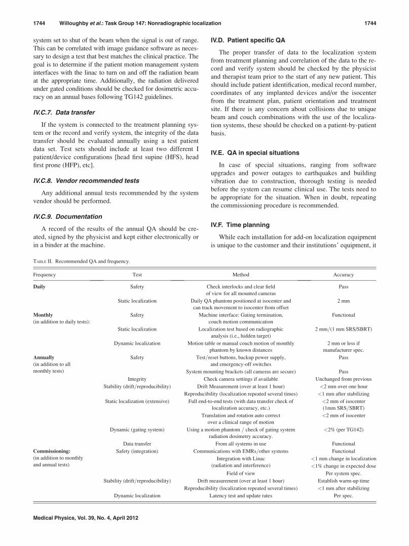
system set to shut of the beam when the signal is out of range.
This can be correlated with image guidance software as neces-
sary to design a test that best matches the clinical practice. The
goal is to determine if the patient motion management system
interfaces with the linac to turn on and off the radiation beam
at the appropriate time. Additionally, the radiation delivered
under gated conditions should be checked for dosimetric accu-
racy on an annual bases following TG142 guidelines.
IV.C.7. Data transfer
If the system is connected to the treatment planning sys-
tem or the record and verify system, the integrity of the data
transfer should be evaluated annually using a test patient
data set. Test sets should include at least two different I
patient/device configurations [head first supine (HFS), head
first prone (HFP), etc].
IV.C.8. Vendor recommended tests
Any additional annual tests recommended by the system
vendor should be performed.
IV.C.9. Documentation
A record of the results of the annual QA should be cre-
ated, signed by the physicist and kept either electronically or
in a binder at the machine.
IV.D. Patient specific QA
The proper transfer of data to the localization system
from treatment planning and correlation of the data to the re-
cord and verify system should be checked by the physicist
and therapist team prior to the start of any new patient. This
should include patient identification, medical record number,
coordinates of any implanted devices and/or the isocenter
from the treatment plan, patient orientation and treatment
site. If there is any concern about collisions due to unique
beam and couch combinations with the use of the localiza-
tion systems, these should be checked on a patient-by-patient
basis.
IV.E. QA in special situations
In case of special situations, ranging from software
upgrades and power outages to earthquakes and building
vibration due to construction, thorough testing is needed
before the system can resume clinical use. The tests need to
be appropriate for the situation. When in doubt, repeating
the commissioning procedure is recommended.
IV.F. Time planning
While each installation for add-on localization equipment
is unique to the customer and their institutions’ equipment, it
TABLE II. Recommended QA and frequency.
Frequency Test Method Accuracy
Daily Safety Check interlocks and clear field
of view for all mounted cameras
Pass
Static localization Daily QA phantom positioned at isocenter and
can track movement to isocenter from offset
2 mm
Monthly
(in addition to daily tests):
Safety Machine interface: Gating termination,
couch motion communication
Functional
Static localization Localization test based on radiographic
analysis (i.e., hidden target)
2 mm=(1 mm SRS/SBRT)
Dynamic localization Motion table or manual couch motion of monthly
phantom by known distances
2 mm or less if
manufacturer spec.
Annually
(in addition to all
monthly tests)
Safety Test=reset buttons, backup power supply,
and emergency-off switches
Pass
System mounting brackets (all cameras are secure) Pass
Integrity Check camera settings if available Unchanged from previous
Stability (drift=reproducibility) Drift Measurement (over at least 1 hour) <2 mm over one hour
Reproducibility (localization repeated several times) <1 mm after stabilizing
Static localization (extensive) Full end-to-end tests (with data transfer check of
localization accuracy, etc.)
<2 mm of isocenter
(1mm SRS=SBRT)
Translation and rotation auto correct
over a clinical range of motion
<2 mm of isocenter
Dynamic (gating system) Using a motion phantom = check of gating system
radiation dosimetry accuracy.
<2% (per TG142)
Data transfer From all systems in use Functional
Commissioning:
(in addition to monthly
and annual tests)
Safety (integration) Communications with EMRs=other systems Functional
Integration with Linac
(radiation and interference)
<1 mm change in localization
<1% change in expected dose
Field of view Per system spec.
Stability (drift=reproducibility) Drift measurement (over at least 1 hour) Establish warm-up time
Reproducibility (localization repeated several times) <1 mm after stabilizing
Dynamic localization Latency test and update rates Per spec.
1744 Willoughby et al.: Task Group 147: Nonradiographic localization 1744
Medical Physics, Vol. 39, No. 4, April 2012
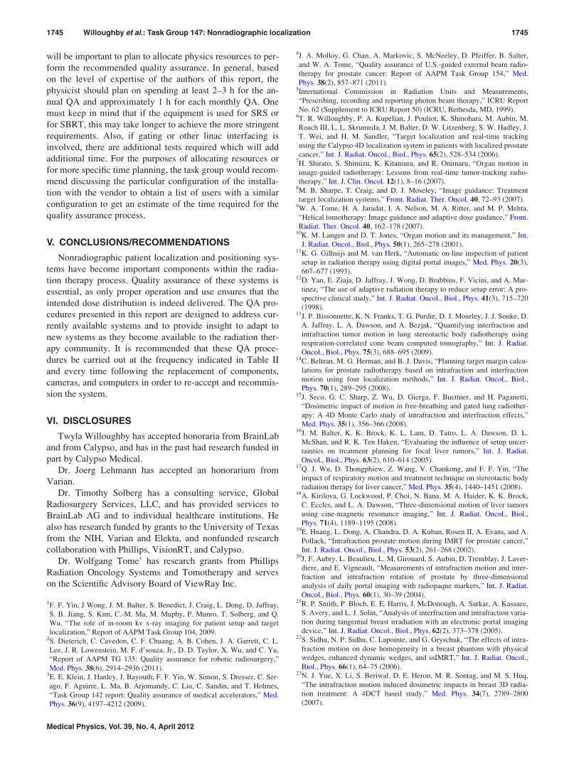
will be important to plan to allocate physics resources to per-
form the recommended quality assurance. In general, based
on the level of expertise of the authors of this report, the
physicist should plan on spending at least 2–3 h for the an-
nual QA and approximately 1 h for each monthly QA. One
must keep in mind that if the equipment is used for SRS or
for SBRT, this may take longer to achieve the more stringent
requirements. Also, if gating or other linac interfacing is
involved, there are additional tests required which will add
additional time. For the purposes of allocating resources or
for more specific time planning, the task group would recom-
mend discussing the particular configuration of the installa-
tion with the vendor to obtain a list of users with a similar
configuration to get an estimate of the time required for the
quality assurance process.
V. CONCLUSIONS/RECOMMENDATIONS
Nonradiographic patient localization and positioning sys-
tems have become important components within the radia-
tion therapy process. Quality assurance of these systems is
essential, as only proper operation and use ensures that the
intended dose distribution is indeed delivered. The QA pro-
cedures presented in this report are designed to address cur-
rently available systems and to provide insight to adapt to
new systems as they become available to the radiation ther-
apy community. It is recommended that these QA proce-
dures be carried out at the frequency indicated in Table II
and every time following the replacement of components,
cameras, and computers in order to re-accept and recommis-
sion the system.
VI. DISCLOSURES
Twyla Willoughby has accepted honoraria from BrainLab
and from Calypso, and has in the past had research funded in
part by Calypso Medical.
Dr. Joerg Lehmann has accepted an honorarium from
Varian.
Dr. Timothy Solberg has a consulting service, Global
Radiosurgery Services, LLC, and has provided services to
BrainLab AG and to individual healthcare institutions. He
also has research funded by grants to the University of Texas
from the NIH, Varian and Elekta, and nonfunded research
collaboration with Phillips, VisionRT, and Calypso.
Dr. Wolfgang Tome’ has research grants from Phillips
Radiation Oncology Systems and Tomotherapy and serves
on the Scientific Advisory Board of ViewRay Inc.
1F. F. Yin, J Wong, J. M. Balter, S. Benedict, J. Craig, L. Dong, D. Jaffray,
S. B. Jiang, S. Kim, C.-M. Ma, M. Muphy, P. Munro, T. Solberg, and Q.
Wu, “The role of in-room kv x-ray imaging for patient setup and target
localization,” Report of AAPM Task Group 104, 2009.2S. Dieterich, C. Cavedon, C. F. Chuang, A. B. Cohen, J. A. Garrett, C. L.
Lee, J. R. Lowenstein, M. F. d’souza, Jr., D. D. Taylor, X. Wu, and C. Yu,
“Report of AAPM TG 135: Quality assurance for robotic radiosurgery,”
Med. Phys. 38(6), 2914–2936 (2011).3E. E. Klein, J. Hanley, J. Bayouth, F. F. Yin, W. Simon, S. Dresser, C. Ser-
ago, F. Aguirre, L. Ma, B. Arjomandy, C. Liu, C. Sandin, and T. Holmes,
“Task Group 142 report: Quality assurance of medical accelerators,” Med.
Phys. 36(9), 4197–4212 (2009).
4J. A. Molloy, G. Chan, A. Markovic, S. McNeeley, D. Pfeiffer, B. Salter,
and W. A. Tome, “Quality assurance of U.S.-guided external beam radio-
therapy for prostate cancer: Report of AAPM Task Group 154,” Med.
Phys. 38(2), 857–871 (2011).5International Commission in Radiation Units and Measurements,
“Prescribing, recording and reporting photon beam therapy,” ICRU Report
No. 62 (Supplement to ICRU Report 50) (ICRU, Bethesda, MD, 1999).6T. R. Willoughby, P. A. Kupelian, J. Pouliot, K. Shinohara, M. Aubin, M.
Roach III, L. L. Skrumeda, J. M. Balter, D. W. Litzenberg, S. W. Hadley, J.
T. Wei, and H. M. Sandler, “Target localization and real-time tracking
using the Calypso 4D localization system in patients with localized prostate
cancer,” Int. J. Radiat. Oncol., Biol., Phys. 65(2), 528–534 (2006).7H. Shirato, S. Shimizu, K. Kitamura, and R. Onimaru, “Organ motion in
image-guided radiotherapy: Lessons from real-time tumor-tracking radio-
therapy,” Int. J. Clin. Oncol. 12(1), 8–16 (2007).8M. B. Sharpe, T. Craig, and D. J. Moseley, “Image guidance: Treatment
target localization systems,” Front. Radiat. Ther. Oncol. 40, 72–93 (2007).9W. A. Tome, H. A. Jaradat, I. A. Nelson, M. A. Ritter, and M. P. Mehta,
“Helical tomotherapy: Image guidance and adaptive dose guidance,” Front.
Radiat. Ther. Oncol. 40, 162–178 (2007).10K. M. Langen and D. T. Jones, “Organ motion and its management,” Int.
J. Radiat. Oncol., Biol., Phys. 50(1), 265–278 (2001).11K. G. Gilhuijs and M. van Herk, “Automatic on-line inspection of patient
setup in radiation therapy using digital portal images,” Med. Phys. 20(3),
667–677 (1993).12D. Yan, E. Ziaja, D. Jaffray, J. Wong, D. Brabbins, F. Vicini, and A. Mar-
tinez, “The use of adaptive radiation therapy to reduce setup error: A pro-
spective clinical study,” Int. J. Radiat. Oncol., Biol., Phys. 41(3), 715–720
(1998).13J. P. Bissonnette, K. N. Franks, T. G. Purdie, D. J. Moseley, J. J. Sonke, D.
A. Jaffray, L. A. Dawson, and A. Bezjak, “Quantifying interfraction and
intrafraction tumor motion in lung stereotactic body radiotherapy using
respiration-correlated cone beam computed tomography,” Int. J. Radiat.
Oncol., Biol., Phys. 75(3), 688–695 (2009).14C. Beltran, M. G. Herman, and B. J. Davis, “Planning target margin calcu-
lations for prostate radiotherapy based on intrafraction and interfraction
motion using four localization methods,” Int. J. Radiat. Oncol., Biol.,
Phys. 70(1), 289–295 (2008).15J. Seco, G. C. Sharp, Z. Wu, D. Gierga, F. Buettner, and H. Paganetti,
“Dosimetric impact of motion in free-breathing and gated lung radiother-
apy: A 4D Monte Carlo study of intrafraction and interfraction effects,”
Med. Phys. 35(1), 356–366 (2008).16J. M. Balter, K. K. Brock, K. L. Lam, D. Tatro, L. A. Dawson, D. L.
McShan, and R. K. Ten Haken, “Evaluating the influence of setup uncer-
tainties on treatment planning for focal liver tumors,” Int. J. Radiat.
Oncol., Biol., Phys. 63(2), 610–614 (2005).17Q. J. Wu, D. Thongphiew, Z. Wang, V. Chankong, and F. F. Yin, “The
impact of respiratory motion and treatment technique on stereotactic body
radiation therapy for liver cancer,” Med. Phys. 35(4), 1440–1451 (2008).18A. Kirilova, G. Lockwood, P. Choi, N. Bana, M. A. Haider, K. K. Brock,
C. Eccles, and L. A. Dawson, “Three-dimensional motion of liver tumors
using cine-magnetic resonance imaging,” Int. J. Radiat. Oncol., Biol.,
Phys. 71(4), 1189–1195 (2008).19E. Huang, L. Dong, A. Chandra, D. A. Kuban, Rosen II, A. Evans, and A.
Pollack, “Intrafraction prostate motion during IMRT for prostate cancer,”
Int. J. Radiat. Oncol., Biol., Phys. 53(2), 261–268 (2002).20J. F. Aubry, L. Beaulieu, L. M. Girouard, S. Aubin, D. Tremblay, J. Laver-
diere, and E. Vigneault, “Measurements of intrafraction motion and inter-
fraction and intrafraction rotation of prostate by three-dimensional
analysis of daily portal imaging with radiopaque markers,” Int. J. Radiat.
Oncol., Biol., Phys. 60(1), 30–39 (2004).21R. P. Smith, P. Bloch, E. E. Harris, J. McDonough, A. Sarkar, A. Kassaee,
S. Avery, and L. J. Solin, “Analysis of interfraction and intrafraction varia-
tion during tangential breast irradiation with an electronic portal imaging
device,” Int. J. Radiat. Oncol., Biol., Phys. 62(2), 373–378 (2005).22S. Sidhu, N. P. Sidhu, C. Lapointe, and G. Gryschuk, “The effects of intra-
fraction motion on dose homogeneity in a breast phantom with physical
wedges, enhanced dynamic wedges, and ssIMRT,” Int. J. Radiat. Oncol.,
Biol., Phys. 66(1), 64–75 (2006).23N. J. Yue, X. Li, S. Beriwal, D. E. Heron, M. R. Sontag, and M. S. Huq,
“The intrafraction motion induced dosimetric impacts in breast 3D radia-
tion treatment: A 4DCT based study,” Med. Phys. 34(7), 2789–2800
(2007).
1745 Willoughby et al.: Task Group 147: Nonradiographic localization 1745
Medical Physics, Vol. 39, No. 4, April 2012
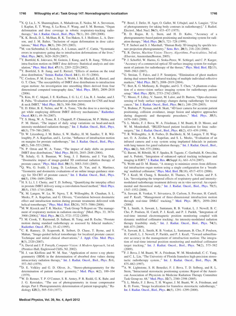
24X. Q. Lu, L. N. Shanmugham, A. Mahadevan, E. Nedea, M. A. Stevenson,
I. Kaplan, E. T. Wong, S. La Rosa, F. Wang, and S. M. Berman, “Organ
deformation and dose coverage in robotic respiratory-tracking radio-
therapy,” Int. J. Radiat. Oncol., Biol., Phys. 71(1), 281–289 (2008).25K. K. Brock, D. L. McShan, R. K. Ten Haken, S. J. Hollister, L. A. Daw-
son, and J. M. Balter, “Inclusion of organ deformation in dose calcu-
lations,” Med. Phys. 30(3), 290–295 (2003).26M. von Siebenthal, G. Szekely, A. J. Lomax, and P. C. Cattin, “Systematic
errors in respiratory gating due to intrafraction deformations of the liver,”
Med. Phys. 34(9), 3620–3629 (2007).27T. Bortfeld, K. Jokivarsi, M. Goitein, J. Kung, and S. B. Jiang, “Effects of
intra-fraction motion on IMRT dose delivery: Statistical analysis and sim-
ulation,” Phys. Med. Biol. 47(13), 2203–2220 (2002).28T. Bortfeld, S. B. Jiang, and E. Rietzel, “Effects of motion on the total
dose distribution,” Semin. Radiat. Oncol. 14(1), 41–51 (2004).29C. Coolens, P. M. Evans, J. Seco, S. Webb, J. M. Blackall, E. Rietzel, and
G. T. Chen, “The susceptibility of IMRT dose distributions to intrafraction
organ motion: An investigation into smoothing filters derived from four
dimensional computed tomography data,” Med. Phys. 33(8), 2809–2818
(2006).30S. Kim, H. C. Akpati, J. E. Kielbasa, J. G. Li, C. Liu, R. J. Amdur, and J.
R. Palta, “Evaluation of intrafraction patient movement for CNS and head
& neck IMRT,” Med. Phys. 31(3), 500–506 (2004).31E. D. Ehler, B. E. Nelms, and W. A. Tome, “On the dose to a moving tar-
get while employing different IMRT delivery mechanisms,” Radiother.
Oncol. 83(1), 49–56 (2007).32T. S. Hong, W. A. Tome, R. J. Chappell, P. Chinnaiyan, M. P. Mehta, and
P. M. Harari, “The impact of daily setup variations on head-and-neck
intensity-modulated radiation therapy,” Int. J. Radiat. Oncol., Biol., Phys.
61(3), 779–788 (2005).33D. W. Litzenberg, J. M. Balter, S. W. Hadley, H. M. Sandler, T. R. Wil-
loughby, P. A. Kupelian, and L. Levine, “Influence of intrafraction motion
on margins for prostate radiotherapy,” Int. J. Radiat. Oncol., Biol., Phys.
65(2), 548–553 (2006).34N. P. Orton and W. A. Tome, “The impact of daily shifts on prostate
IMRT dose distributions,” Med. Phys. 31(10), 2845–2848 (2004).35B. Schaly, G. S. Bauman, W. Song, J. J. Battista, and J. Van Dyk,
“Dosimetric impact of image-guided 3D conformal radiation therapy of
prostate cancer,” Phys. Med. Biol. 50(13), 3083–3101 (2005).36Q. Wu, G. Ivaldi, J. Liang, D. Lockman, D. Yan, and A. Martinez,
“Geometric and dosimetric evaluations of an online image-guidance strat-
egy for 3D-CRT of prostate cancer,” Int. J. Radiat. Oncol., Biol., Phys.
64(5), 1596–1609 (2006).37H. S. Li, I. J. Chetty, and T. D. Solberg, “Quantifying the interplay effect
in prostate IMRT delivery using a convolution-based method,” Med. Phys.
35(5), 1703–1710 (2008).38K. M. Langen, W. Lu, W. Ngwa, T. R. Willoughby, B. Chauhan, S. L.
Meeks, P. A. Kupelian, and G. Olivera, “Correlation between dosimetric
effect and intrafraction motion during prostate treatments delivered with
helical tomotherapy,” Phys. Med. Biol. 53(24), 7073–7086 (2008).39M. W. Kissick and T. R. Mackie, “Task Group 76 Report on ‘The manage-
ment of respiratory motion in radiation oncology’ [Med. Phys. 33, 3874-
3900 (2006)],” Med. Phys. 36(12), 5721–5722 (2009).40J. M. Crook, Y. Raymond, D. Salhani, H. Yang, and B. Esche, “Prostate
motion during standard radiotherapy as assessed by fiducial markers,”
Radiother. Oncol. 37(1), 35–42 (1995).41C. R. Ramsey, D. Scaperoth, R. Seibert, D. Chase, T. Byrne, and S.
Mahan, “Image-guided helical tomotherapy for localized prostate cancer:
Technique and initial clinical observations,” J. Appl. Clin. Med. Phys.
8(3), 2320 (2007).42A. David and J. P. Forsyth, Computer Vision: A Modern Approach, 1st ed.
(Prentice-Hall, Englewood Cliffs, NJ, 2002).43H. J. van Kleffens and W. M. Star, “Application of stereo x-ray photo-
grammetry (SRM) in the determination of absorbed dose values during
intracavitary radiation therapy,” Int. J. Radiat. Oncol., Biol., Phys. 5(4),
557–563 (1979).44D. E. Velkley and G. D. Oliver, Jr., “Stereo-photogrammetry for the
determination of patient surface geometry,” Med. Phys. 6(2), 100–104
(1979).45W. D. Renner, T. P. O’Connor, S. R. Amtey, P. R. Reddi, G. K. Bahr, and
J. G. Kereiakes, “The use of photogrammetry in tissue compensator
design. Part I: Photogrammetric determination of patient topography,” Ra-
diology 125(2), 505–510 (1977).
46F. Borel, J. Defer, H. Aget, O. Gallet, M. Urbajtel, and A. Laugier, “[Use
of photogrammetry for taking body contours in radiotherapy],” J. Radiol.
Electrol., Med. Nucl. 56(5), 433–437 (1975).47R. D. Rogus, R. L. Stern, and H. D. Kubo, “Accuracy of a
photogrammetry-based patient positioning and monitoring system for radi-
ation therapy,” Med. Phys. 26(5), 721–728 (1999).48J. P. Siebert and S. J. Marshall, “Human Body 3D imaging by speckle tex-
ture projection photogrammetry,” Sens. Rev. 20(3), 218–226 (2000).49E. R. Davies, Machine Vision: Theory, Algorithms, Practicalities, 3rd ed.
(Elsevier, Amsterdam/Boston, 2005).50P. J. Schoffel, W. Harms, G. Sroka-Perez, W. Schlegel, and C. P. Karger,
“Accuracy of a commercial optical 3D surface imaging system for realign-
ment of patients for radiotherapy of the thorax,” Phys. Med. Biol. 52(13),
3949–3963 (2007).51G. Stroian, T. Falco, and J. P. Seuntjens, “Elimination of ghost markers
during dual sensor-based infrared tracking of multiple individual reflective
markers,” Med. Phys. 31(7), 2008–2019 (2004).52C. Bert, K. G. Metheany, K. Doppke, and G. T. Chen, “A phantom evalua-
tion of a stereo-vision surface imaging system for radiotherapy patient
setup,” Med. Phys. 32(9), 2753–2762 (2005).53C. Moore, F. Lilley, V. Sauret, M. Lalor, and D. Burton, “Opto-electronic
sensing of body surface topology changes during radiotherapy for rectal
cancer,” Int. J. Radiat. Oncol., Biol., Phys. 56(1), 248–258 (2003).54A. Brahme, P. Nyman, and B. Skatt, “4D laser camera for accurate patient
positioning, collision avoidance, image fusion and adaptive approaches
during diagnostic and therapeutic procedures,” Med. Phys. 35(5),
1670–1681 (2008).55S. L. Meeks, F. J. Bova, W. A. Friedman, J. M. Buatti, R. D. Moore, and
W. M. Mendenhall, “IRLED-based patient localization for linac radio-
surgery,” Int. J. Radiat. Oncol., Biol., Phys. 41(2), 433–439 (1998).56T. R. Willoughby, A. R. Forbes, D. Buchholz, K. M. Langen, T. H. Wag-
ner, O. A. Zeidan, P. A. Kupelian, and S. L. Meeks, “Evaluation of an
infrared camera and x-ray system using implanted fiducials in patients
with lung tumors for gated radiation therapy,” Int. J. Radiat. Oncol., Biol.,
Phys. 66(2), 568–575 (2006).57G. Baroni, M. Riboldi, M. F. Spadea, B. Tagaste, C. Garibaldi, R. Orecchia,
and A. Pedotti, “Integration of enhanced optical tracking techniques and
imaging in IGRT,” J. Radiat. Res. 48(Suppl A), A61–A74 (2007).58S. Webb and D. M. Binnie, “A strategy to minimize errors from differen-
tial intrafraction organ motion using a single configuration for a ‘breath-
ing’ multileaf collimator,” Phys. Med. Biol. 51(18), 4517–4531 (2006).59P. J. Keall, M. Chang, S. Benedict, H. Thames, S. S. Vedam, and P. S.
Lin, “Investigating the temporal effects of respiratory-gated and intensity-
modulated radiotherapy treatment delivery on in vitro survival: An experi-
mental and theoretical study,” Int. J. Radiat. Oncol., Biol., Phys. 71(5),
1547–1552 (2008).60A. Sawant, R. Venkat, V. Srivastava, D. Carlson, S. Povzner, H. Cattell,
and P. Keall, “Management of three-dimensional intrafraction motion
through real-time DMLC tracking,” Med. Phys. 35(5), 2050–2061
(2008).61R. L. Smith, A. Sawant, L. Santanam, R. B. Venkat, L. J. Newell, B. C.
Cho, P. Poulsen, H. Catell, P. J. Keall, and P. J. Parikh, “Integration of
real-time internal electromagnetic position monitoring coupled with
dynamic multileaf collimator tracking: An intensity-modulated radiation
therapy feasibility study,” Int. J. Radiat. Oncol., Biol., Phys. 74(3),
868–875 (2009).62A. Sawant, R. L. Smith, R. B. Venkat, L. Santanam, B. Cho, P. Poulsen,
H. Cattell, L. J. Newell, P. Parikh, and P. J. Keall, “Toward submillim-
eter accuracy in the management of intrafraction motion: The integra-
tion of real-time internal position monitoring and multileaf collimator
target tracking,” Int. J. Radiat. Oncol., Biol., Phys. 74(2), 575–582
(2009).63F. J. Bova, J. M. Buatti, W. A. Friedman, W. M. Mendenhall, C. C. Yang,
and C. L. Liu, “The Univeristy of Florida frameless high-precision stereo-
tactic radiotherapy system.,” Int. J. Radiat. Oncol., Biol., Phys. 38,
875–882 (1997).64A. W. Lightstone, S. H. Benedict, F. J. Bova, T. D. Solberg, and R. L.
Stern, “Intracranial stereotactic positioning systems: Report of the Ameri-
can Association of Physicists in Medicine Radiation Therapy Committee
Task Group no. 68,” Med. Phys. 32(7), 2380–2398 (2005).65S. L. Meeks, F. J. Bova, T. H. Wagner, J. M. Buatti, W. A. Friedman, and
K. D. Foote, “Image localization for frameless stereotactic radiotherapy,”
Int. J. Radiat. Oncol., Biol., Phys. 46(5), 1291–1299 (2000).
1746 Willoughby et al.: Task Group 147: Nonradiographic localization 1746
Medical Physics, Vol. 39, No. 4, April 2012

66W. A. Tome, S. L. Meeks, J. M. Buatti, F. J. Bova, W. A. Friedman, and
Z. Li, “A high-precision system for conformal intracranial radiotherapy,”
Int. J. Radiat. Oncol., Biol., Phys. 47(4), 1137–1143 (2000).67W. A. Tome, S. L. Meeks, T. R. McNutt, J. M. Buatti, F. J. Bova, W. A.
Friedman, and M. Mehta, “Optically guided intensity modulated radio-
therapy,” Radiother. Oncol. 61(1), 33–44 (2001).68S. S. Korreman, T. Juhler-Nottrup, and A. L. Boyer, “Respiratory gated
beam delivery cannot facilitate margin reduction, unless combined with
respiratory correlated image guidance,” Radiother. Oncol. 86(1), 61–68
(2008).69E. Yorke, K. E. Rosenzweig, R. Wagman, and G. S. Mageras,
“Interfractional anatomic variation in patients treated with respiration-
gated radiotherapy,” J. Appl. Clin. Med. Phys. 6(2), 19–32 (2005).70C. Bert, K. G. Metheany, K. P. Doppke, A. G. Taghian, S. N. Powell, and
G. T. Chen, “Clinical experience with a 3D surface patient setup system
for alignment of partial-breast irradiation patients,” Int. J. Radiat. Oncol.,
Biol., Phys. 64(4), 1265–1274 (2006).71D. P. Gierga, M. Riboldi, J. C. Turcotte, G. C. Sharp, S. B. Jiang, A. G.
Taghian, and G. T. Chen, “Comparison of target registration errors for
multiple image-guided techniques in accelerated partial breast irradiation,”
Int. J. Radiat. Oncol., Biol., Phys. 70(4), 1239–1246 (2008).72M. Krengli, S. Gaiano, E. Mones, A. Ballare, D. Beldi, C. Bolchini, and
G. Loi, “Reproducibility of patient setup by surface image registration sys-
tem in conformal radiotherapy of prostate cancer,” Radiat. Oncol. 4, 9
(2009).73L. I. Cervino, T. Pawlicki, J. D. Lawson, and S. B. Jiang, “Frame-less and
mask-less cranial stereotactic radiosurgery: A feasibility study,” Phys.
Med. Biol. 55(7), 1863–1873 (2010).74A. Wagner, K. Schicho, W. Birkfellner, M. Figl, R. Seemann, F. Konig, F.
Kainberger, and R. Ewers, “Quantitative analysis of factors affecting intra-
operative precision and stability of optoelectronic and electromagnetic
tracking systems,” Med. Phys. 29(5), 905–912 (2002).75D. C. Barratt, A. H. Davies, A. D. Hughes, S. A. Thom, and K. N. Humph-
ries, “Optimisation and evaluation of an electromagnetic tracking device
for high-accuracy three-dimensional ultrasound imaging of the carotid
arteries,” Ultrasound. Med. Biol. 27(7), 957–968 (2001).76C. J. Hsu, Y. W. Chang, W. Y. Chou, C. P. Chiou, W. N. Chang, and C.
Y. Wong, “Measurement of spinal range of motion in healthy individuals
using an electromagnetic tracking device,” J. Neurosurg. Spine 8(2),
135–142 (2008).77J. B. Hummel, M. R. Bax, M. L. Figl, Y. Kang, C. Maurer, Jr., W. W.
Birkfellner, H. Bergmann, and R. Shahidi, “Design and application of an
assessment protocol for electromagnetic tracking systems,” Med. Phys.
32(7), 2371–2379 (2005).78C. G. Meskers, H. Fraterman, F. C. van der Helm, H. M. Vermeulen, and
P. M. Rozing, “Calibration of the “Flock of Birds” electromagnetic track-
ing device and its application in shoulder motion studies,” J. Biomech.
32(6), 629–633 (1999).79M. P. Fried, J. Kleefield, H. Gopal, E. Reardon, B. T. Ho, and F. A. Kuhn,
“Image-guided endoscopic surgery: Results of accuracy and performance
in a multicenter clinical study using an electromagnetic tracking system,”
Laryngoscope 107(5), 594–601 (1997).80A. D. Milne, D. G. Chess, J. A. Johnson, and G. J. King, “Accuracy of an
electromagnetic tracking device: A study of the optimal range and metal
interference,” J. Biomech. 29(6), 791–793 (1996).81J. M. Balter, J. N. Wright, L. J. Newell, B. Friemel, S. Dimmer, Y. Cheng,
J. Wong, E. Vertatschitsch, and T. P. Mate, “Accuracy of a wireless local-
ization system for radiotherapy,” Int. J. Radiat. Oncol., Biol., Phys. 61(3),
933–937 (2005).82D. W. Litzenberg, T. R. Willoughby, J. M. Balter, H. M. Sandler, J. Wei,
P. A. Kupelian, A. A. Cunningham, A. Bock, M. Aubin, M. Roach III, K.
Shinohara, and J. Pouliot, “Positional stability of electromagnetic trans-
ponders used for prostate localization and continuous, real-time tracking,”
Int. J. Radiat. Oncol., Biol., Phys. 68(4), 1199–1206 (2007).83L. Santanam, K. Malinowski, J. Hubenshmidt, S. Dimmer, M. L. Mayse,
J. Bradley, A. Chaudhari, K. Lechleiter, S. K. Goddu, J. Esthappan,
S. Mutic, D. A. Low, and P. Parikh, “Fiducial-based translational localiza-
tion accuracy of electromagnetic tracking system and on-board kilovoltage
imaging system,” Int. J. Radiat. Oncol., Biol., Phys. 70(3), 892–899
(2008).84J. Kindblom, A. M. Ekelund-Olvenmark, H. Syren, R. Iustin, K. Braide, I.
Frank-Lissbrant, and B. Lennernas, “High precision transponder localiza-
tion using a novel electromagnetic positioning system in patients with
localized prostate cancer,” Radiother. Oncol. 90(3), 307–311 (2009).85T. Shchory, D. Schifter, R. Lichtman, D. Neustadter, and B. W. Corn,
“Tracking accuracy of a real-time fiducial tracking system for patient posi-
tioning and monitoring in radiation therapy,” Int. J. Radiat. Oncol., Biol.,
Phys. 78(4), 1227–1234.86D. Neustadter, G. Barnea, S. Stokar, and B. Corn, “Analysis of dose to
patient, spouse/caretaker, and staff, from an implanted trackable radioac-
tive fiducial for use in the radiation treatment of prostate cancer,” Med.
Phys. 37(3), 1220–1224.87D. Neustadter, M. Tune, A. Zaretsky, R. Shofti, A. Kushnir, T. Harel, D.
Carmi-Yinon, and B. Corn, “Stability, visibility, and histologic analysis of
a new implanted fiducial for use as a kilovoltage radiographic or radioac-
tive marker for patient positioning and monitoring in radiotherapy,” Int. J.
Radiat. Oncol., Biol., Phys. 77(4), 1240–1247 (2010).88M. Van Herk, “Errors and margins in radiotherapy,” Semin. Radiat. Oncol.
24(1), 52–64 (2004).89W. Lutz, K. R. Winston, and N. Maleki, “A system for stereotactic radio-
surgery with a linear accelerator,” Int. J. Radiat. Oncol., Biol., Phys.
14(2), 373–381 (1988).90B. R. Thomadsen, H. T. Heaton II, S. K. Jani, J. P. Masten, M. E. Napoli-
tano, Z. Ouhib, C. S. Reft, M. J. Rivard, T. T. Robin, M. Subramanian,
and O. H. Suleiman, “Off-label use of medical products in radiation ther-
apy: Summary of the report of AAPM Task Group No. 121,” Med. Phys.
37(5), 2300–2311 (2010).91S. L. Meeks, W. A. Tome, T. R. Willoughby, P. A. Kupelian, T. H. Wag-
ner, J. M. Buatti, and F. J. Bova, “Optically guided patient positioning
techniques,” Semin. Radiat. Oncol. 15(3), 192–201 (2005).92M. H. Phillips, K. Singer, E. Miller, and K. Stelzer, “Commissioning an
image-guided localization system for radiotherapy,” Int. J. Radiat. Oncol.,
Biol., Phys. 48(1), 267–276 (2000).93S. L. Meeks, W. A. Tome, and L. G. Bouchet, “Patient positioning using op-
tical and ultrasound techniques,” in Intensity Modulated Radiotherapy, Stateof the Art (Medical Physics Publishing, College Park, MD (2003), 727–748.
94N. Hayashi, Y. Obata, Y. Uchiyama, Y. Mori, C. Hashizume, and T.
Kobayashi, “Assessment of spatial uncertainties in the radiotherapy pro-
cess with the Novalis system,” Int. J. Radiat. Oncol., Biol., Phys. 75(2),
549–557 (2009).95M. Serban, E. Heath, G. Stroian, D. L. Collins, and J. Seuntjens, “A de-
formable phantom for 4D radiotherapy verification: Design and image
registration evaluation,” Med. Phys. 35(3), 1094–1102 (2008).96J. R. van Sornsen de Koste, J. P. Cuijpers, F. G. de Geest, F. J. Lager-
waard, B. J. Slotman, and S. Senan, “Verifying 4D gated radiotherapy
using time-integrated electronic portal imaging: A phantom and clinical
study,” Radiat. Oncol. 2, 32 (2007).97P. J. Keall, H. Cattell, D. Pokhrel, S. Dieterich, K. H. Wong, M. J. Mur-
phy, S. S. Vedam, K. Wijesooriya, and R. Mohan, “Geometric accuracy of
a real-time target tracking system with dynamic multileaf collimator track-
ing system,” Int. J. Radiat. Oncol., Biol., Phys. 65(5), 1579–1584 (2006).98L. Santanam, C. Noel, T. R. Willoughby, J. Esthappan, S. Mutic, E. E.
Klein, D. A. Low, and P. J. Parikh, “Quality assurance for clinical imple-
mentation of an electromagnetic tracking system,” Med. Phys. 36(8),
3477–3486 (2009).99S. B. Jiang, J. Wolfgang, and G. S. Mageras, “Quality assurance chal-
lenges for motion-adaptive radiation therapy: Gating, breath holding, and
four-dimensional computed tomography,” Int. J. Radiat. Oncol., Biol.,
Phys. 71(1 Suppl), S103–107 (2008).100G. J. Kutcher et al., “Comprehensive QA for radiation oncology: Report
of AAPM Radiation Therapy Committee Task Group 40,” Med. Phys.
21(4), 581–618 (1994).
1747 Willoughby et al.: Task Group 147: Nonradiographic localization 1747
Medical Physics, Vol. 39, No. 4, April 2012