Embed Size (px)
Citation preview
O r i g i n a l a r t i c l e
Dental Press J Orthod 103 2010 July-Aug;15(4):103-16
Qualitative photoelastic study of the force system produced by retraction T-springs with different preactivations
Luiz Guilherme Martins Maia*, Vanderlei Luiz Gomes**, Ary dos Santos-Pinto***, Itamar Lopes Júnior****, Luiz Gonzaga Gandini Jr.*****
Objective: Evaluate the force system produced by the T-spring used for space closure. Methods: By means of the experimental photoelastic method, we evaluated the T-spring—used for space closure—with two different preactivations on its apical portion, i.e., one with 30° and one with 45º. The springs were fabricated with rectangular 0.017 X 0.025-in titanium-molybdenum alloy (TMA), centered in a 27.0 mm interbracket space and activated at 5.0 mm, at 2.5 mm, and in a neutral position. For more reliable results, tests were repeated on three photoelastic models duplicated and prepared by the same operator. To better understand the results, the fringes seen in the polariscope were pho-tographed and analyzed qualitatively. Results: Through qualitative analysis of the fringes order in the photoelastic model it was noted that at the retraction and anchoring ends the T-spring with 30° apical activation showed a slightly greater accumulation of energy relative to the force system that was generated.
Abstract
Keywords: Closing of orthodontic space. T loop. Photoelastic study. Retraction.
* Professor of Orthodontics, Dental School, Tiradentes University/SE. Head of the Specialization Course in Othodontics, Tiradentes University/SE. Specialist in Orthodontics, EAP/APCD - UNESP/Araraquara. MSc in Dental Sciences, Orthodontics, Araraquara Dental School - UNESP.
** Head Professor, Removable Prosthodontics and Dental Materials, Dental School, Federal University of Uberlândia. MSc and PhD in Dentistry, USP, Ribeirão Preto – São Paulo.
*** Head and Adjunct Professor of Orthodontics, Children’s Clinic Department, Araraquara Dental School, UNESP. **** Masters Student in Oral Rehabilitation, Federal University of Uberlândia. ***** Head and Adjunct Professor of Orthodontics, Children’s Clinic Department, Araraquara Dental School, UNESP. Assistant Adjunct Clinical Pro-
fessor Department of Orthodontics, Baylor College of Dentistry-Dallas-TX.
IntROductIOnThe extraction philosophy advocated by
Tweed in the 1940s raised a new perspective for orthodontic treatment, arousing the interest of orthodontists in mechanical retraction. Since then several mechanical devices have been de-
veloped for this purpose and knowledge about the force system generated by each of them has become a constant focus of research.16,17
In performing retraction movements, or-thodontists must be knowledgeable of the mechanical principles involved in this system
Qualitative photoelastic study of the force system produced by retraction T-springs with different preactivations
Dental Press J Orthod 104 2010 July-Aug;15(4):103-16
to ensure that tooth movement occurs with maximum effectiveness and minimum strain on adjacent periodontal tissues.1,12 Ideally, space closure should be accomplished by re-traction movement resulting from “loop” type orthodontic appliances. In this case, forces be-come predictable as they are in close relation-ship with archwire size, loop design, alloy type, spring position, amount of activation, force constancy, force magnitude and momentum magnitude.2,3,10,11,13,14,18-21,23,24
In “sliding” type retraction appliances, how-ever, the force system that is generated becomes less predictable since the magnitude of force is difficult to measure as part of it is dissipated by friction during movement.1,12
Burstone,2 in 1982, cited three properties that any device should display during retraction movement: a momentum/force ratio, achieved by incorporating Gable-like bends and preacti-vation bends; force magnitude during activation and a load/deflection ratio, represented by the amount of energy lost during deactivations.
Another important property of the treatment plan is the anchorage type one wishes to obtain to ensure adequate dental relationship.2,14 In this context, the T-spring designed by Burstone and Koenig3 adds several ideal efficiency features that optimize space closure. The biomechanical properties of this spring have been the subject of many studies in the orthodontic community and its force system has been widely dissemi-nated2,3,10,11,19-22,24 in investigations involving me-chanical tests3,10,11,17-24 and finite elements meth-od.13 Hence the interest in evaluating this system by the experimental photoelastic method.5-9,15,25
The T-spring is often utilized in research un-dertaken at the Graduate Orthodontic Clinic of the School of Dentistry of Araraquara, São Paulo State, Brazil. The purpose of this study was to eval-uate, by means of photoelasticity5-9,15,25, the force system of a T-spring centered in the interbracket space using two different preactivation types.14,20,21
MAtERIAL And MEtHOdSInitially, tests were performed on 5 experi-
mental pilot models in order to determine prop-er methodology research, materials to be used, number of repetitions needed, model fabrication technique, reading technique and researcher cali-bration to ensure result accuracy.15
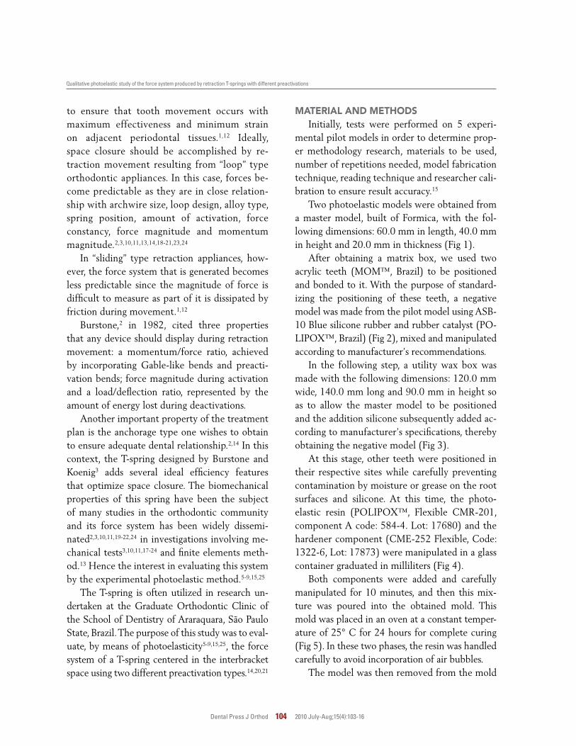
Two photoelastic models were obtained from a master model, built of Formica, with the fol-lowing dimensions: 60.0 mm in length, 40.0 mm in height and 20.0 mm in thickness (Fig 1).
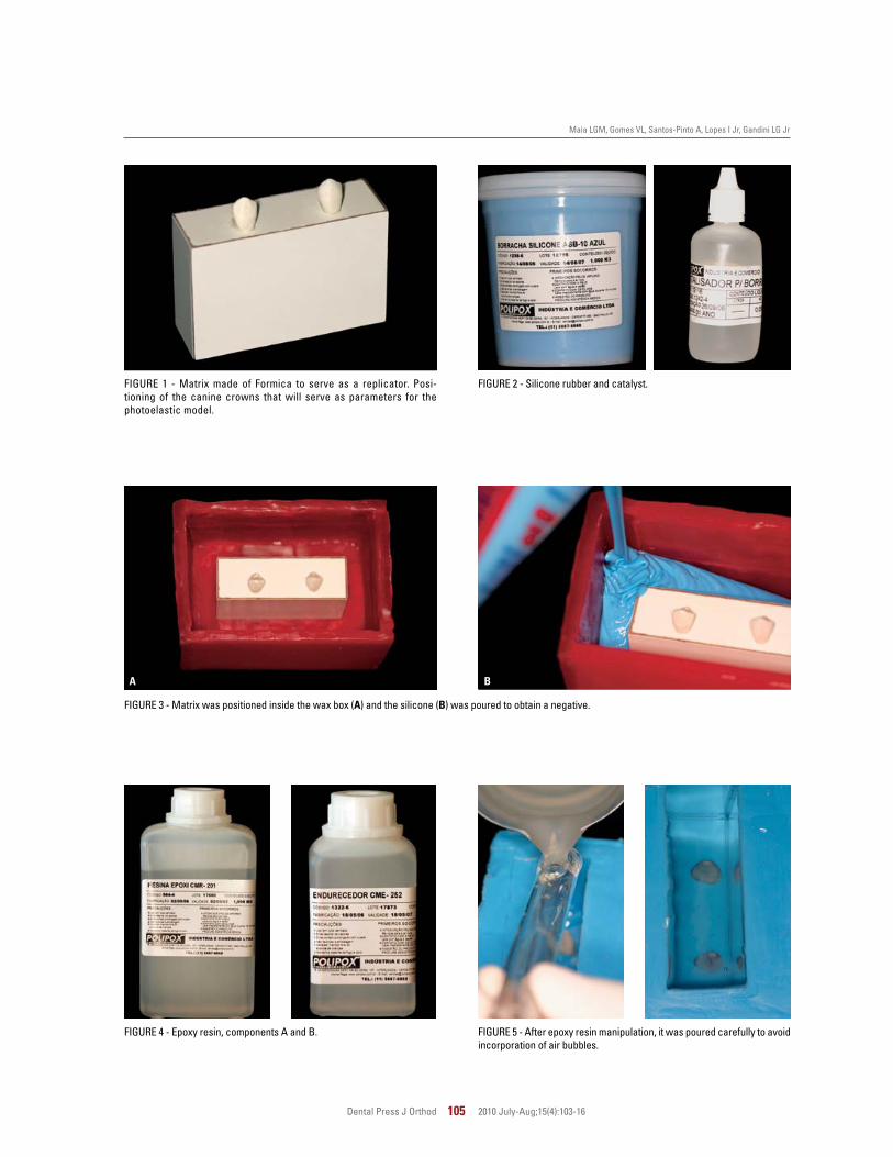
After obtaining a matrix box, we used two acrylic teeth (MOM™, Brazil) to be positioned and bonded to it. With the purpose of standard-izing the positioning of these teeth, a negative model was made from the pilot model using ASB-10 Blue silicone rubber and rubber catalyst (PO-LIPOX™, Brazil) (Fig 2), mixed and manipulated according to manufacturer’s recommendations.
In the following step, a utility wax box was made with the following dimensions: 120.0 mm wide, 140.0 mm long and 90.0 mm in height so as to allow the master model to be positioned and the addition silicone subsequently added ac-cording to manufacturer’s specifications, thereby obtaining the negative model (Fig 3).
At this stage, other teeth were positioned in their respective sites while carefully preventing contamination by moisture or grease on the root surfaces and silicone. At this time, the photo-elastic resin (POLIPOX™, Flexible CMR-201, component A code: 584-4. Lot: 17680) and the hardener component (CME-252 Flexible, Code: 1322-6, Lot: 17873) were manipulated in a glass container graduated in milliliters (Fig 4).
Both components were added and carefully manipulated for 10 minutes, and then this mix-ture was poured into the obtained mold. This mold was placed in an oven at a constant temper-ature of 25° C for 24 hours for complete curing (Fig 5). In these two phases, the resin was handled carefully to avoid incorporation of air bubbles.
The model was then removed from the mold
A B
Maia LGM, Gomes VL, Santos-Pinto A, Lopes I Jr, Gandini LG Jr
Dental Press J Orthod 105 2010 July-Aug;15(4):103-16
FIGURE 1 - Matrix made of Formica to serve as a replicator. Posi-tioning of the canine crowns that will serve as parameters for the photoelastic model.
FIGURE 3 - Matrix was positioned inside the wax box (A) and the silicone (B) was poured to obtain a negative.
FIGURE 2 - Silicone rubber and catalyst.
FIGURE 4 - Epoxy resin, components A and B. FIGURE 5 - After epoxy resin manipulation, it was poured carefully to avoid incorporation of air bubbles.
Qualitative photoelastic study of the force system produced by retraction T-springs with different preactivations
Dental Press J Orthod 106 2010 July-Aug;15(4):103-16
FIGURE 6 - Photoelastic model.
FIGURE 7 - Photoelastic model with ‘crossed’ tubes in position.
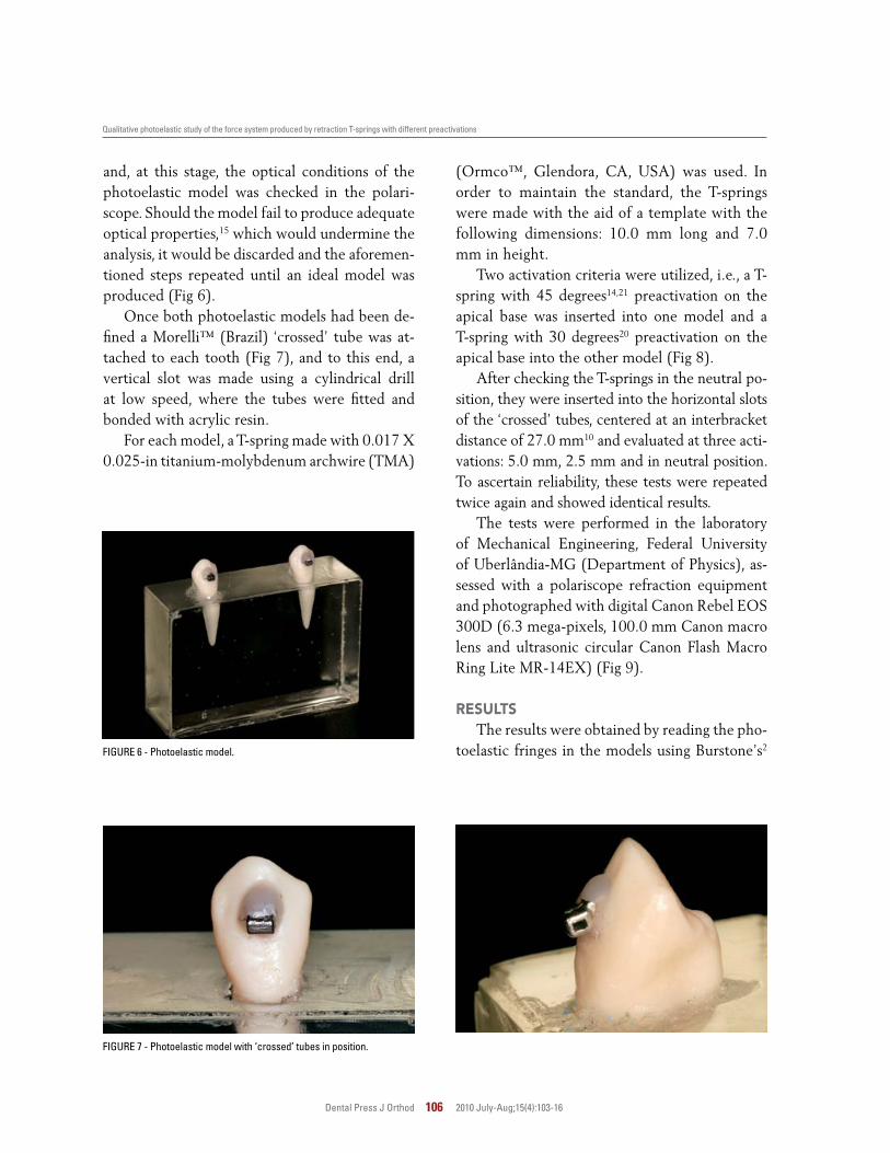
and, at this stage, the optical conditions of the photoelastic model was checked in the polari-scope. Should the model fail to produce adequate optical properties,15 which would undermine the analysis, it would be discarded and the aforemen-tioned steps repeated until an ideal model was produced (Fig 6).
Once both photoelastic models had been de-fined a Morelli™ (Brazil) ‘crossed’ tube was at-tached to each tooth (Fig 7), and to this end, a vertical slot was made using a cylindrical drill at low speed, where the tubes were fitted and bonded with acrylic resin.
For each model, a T-spring made with 0.017 X 0.025-in titanium-molybdenum archwire (TMA)
(Ormco™, Glendora, CA, USA) was used. In order to maintain the standard, the T-springs were made with the aid of a template with the following dimensions: 10.0 mm long and 7.0 mm in height.
Two activation criteria were utilized, i.e., a T-spring with 45 degrees14,21 preactivation on the apical base was inserted into one model and a T-spring with 30 degrees20 preactivation on the apical base into the other model (Fig 8).
After checking the T-springs in the neutral po-sition, they were inserted into the horizontal slots of the ‘crossed’ tubes, centered at an interbracket distance of 27.0 mm10 and evaluated at three acti-vations: 5.0 mm, 2.5 mm and in neutral position. To ascertain reliability, these tests were repeated twice again and showed identical results.
The tests were performed in the laboratory of Mechanical Engineering, Federal University of Uberlândia-MG (Department of Physics), as-sessed with a polariscope refraction equipment and photographed with digital Canon Rebel EOS 300D (6.3 mega-pixels, 100.0 mm Canon macro lens and ultrasonic circular Canon Flash Macro Ring Lite MR-14EX) (Fig 9).
RESuLtSThe results were obtained by reading the pho-
toelastic fringes in the models using Burstone’s2

A
B CB D c
Maia LGM, Gomes VL, Santos-Pinto A, Lopes I Jr, Gandini LG Jr
Dental Press J Orthod 107 2010 July-Aug;15(4):103-16
FIGURE 8 - Template to standardize the fabrication of Souza standard (30 degrees) and Marcotte standard (45 degrees) T-springs.
FIGURE 9 - Flat circular polariscope: (A) light source, (B) polarizers, (C) photoelastic model and (D) digital photographic equipment.
30 degrees in the apical base
45 degrees in the apical base
T-springs with two different types of preactiva-tion.14,20,21 The spring was analyzed in three dif-ferent positions: (1) in a neutral position, (2) with 2.5 mm activation, and (3) with 5.0 mm activation.
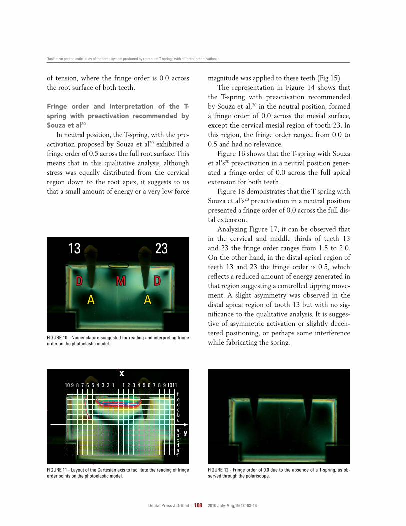
The interpretations were evaluated descrip-tively and the readings made in charts divided into the three portions of each tooth, i.e., one mesial, one apical and one distal, which were evaluated one by one separately and then com-pared with the adjacent teeth (Fig 10).
The reading of the fringes order was accom-
plished through the interface of the violet and blue colors, formed on the distal, mesial and api-cal surfaces of each tooth, using the distance as reference for building the analysis charts. On an increasing scale, the following colors are formed: black, yellow, red, blue, yellow, red, green, yellow, red and green (Fig 11).
Figure 12 shows the fringe order of 0.0 in the photoelastic model due to the absence of a T-spring. In this case, the photoelastic model is free from any force interference.
Figure 13 represents a photoelastic model free
A
13 23
AD DM
10 1011
fedcba
a`b`c`d`e`f`
9 98 87 76 65 54 43 32 21 1
x
y
Qualitative photoelastic study of the force system produced by retraction T-springs with different preactivations
Dental Press J Orthod 108 2010 July-Aug;15(4):103-16
of tension, where the fringe order is 0.0 across the root surface of both teeth.
Fringe order and interpretation of the t-spring with preactivation recommended by Souza et al20
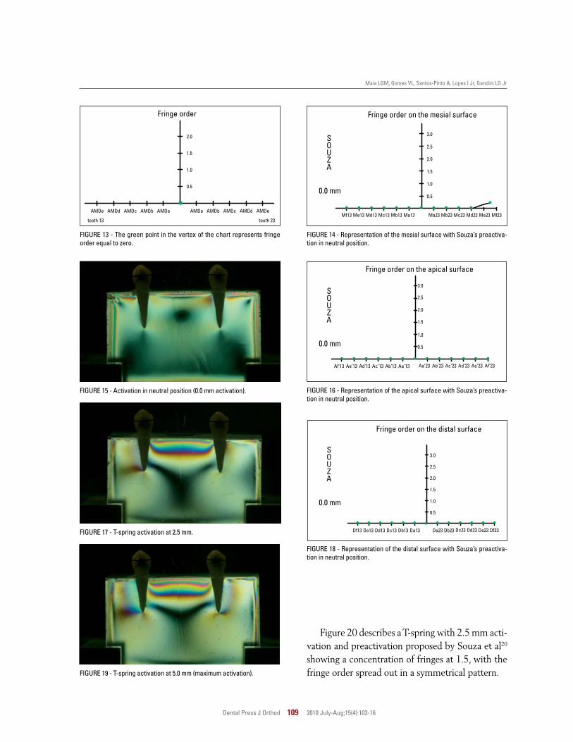
In neutral position, the T-spring, with the pre-activation proposed by Souza et al20 exhibited a fringe order of 0.5 across the full root surface. This means that in this qualitative analysis, although stress was equally distributed from the cervical region down to the root apex, it suggests to us that a small amount of energy or a very low force
magnitude was applied to these teeth (Fig 15).The representation in Figure 14 shows that
the T-spring with preactivation recommended by Souza et al,20 in the neutral position, formed a fringe order of 0.0 across the mesial surface, except the cervical mesial region of tooth 23. In this region, the fringe order ranged from 0.0 to 0.5 and had no relevance.
Figure 16 shows that the T-spring with Souza et al’s20 preactivation in a neutral position gener-ated a fringe order of 0.0 across the full apical extension for both teeth.
Figure 18 demonstrates that the T-spring with Souza et al’s20 preactivation in a neutral position presented a fringe order of 0.0 across the full dis-tal extension.
Analyzing Figure 17, it can be observed that in the cervical and middle thirds of teeth 13 and 23 the fringe order ranges from 1.5 to 2.0. On the other hand, in the distal apical region of teeth 13 and 23 the fringe order is 0.5, which reflects a reduced amount of energy generated in that region suggesting a controlled tipping move-ment. A slight asymmetry was observed in the distal apical region of tooth 13 but with no sig-nificance to the qualitative analysis. It is sugges-tive of asymmetric activation or slightly decen-tered positioning, or perhaps some interference while fabricating the spring.
FIGURE 10 - Nomenclature suggested for reading and interpreting fringe order on the photoelastic model.
FIGURE 11 - Layout of the Cartesian axis to facilitate the reading of fringe order points on the photoelastic model.
FIGURE 12 - Fringe order of 0.0 due to the absence of a T-spring, as ob-served through the polariscope.
AMDe AMDaAMDd AMDbAMDc AMDcAMDb AMDdAMDa AMDeMf13 Me13 Md13 Mc13 Mb13 Ma13 Ma23 Mb23 Mc23 Md23 Me23 Mf23
S O U Z A
Af’13 Ae’13 Ad’13 Ac’13 Ab’13 Aa’13 Aa’23 Ab’23 Ac’23 Ad’23 Ae’23 Af’23
S O U Z A
Df13 De13 Dd13 Dc13 Db13 Da13 Da23 Db23 Dc23 Dd23 De23 Df23
S O U Z A
Maia LGM, Gomes VL, Santos-Pinto A, Lopes I Jr, Gandini LG Jr
Dental Press J Orthod 109 2010 July-Aug;15(4):103-16
FIGURE 15 - Activation in neutral position (0.0 mm activation).
Fringe order on the mesial surface
FIGURE 17 - T-spring activation at 2.5 mm.
Fringe order on the distal surface
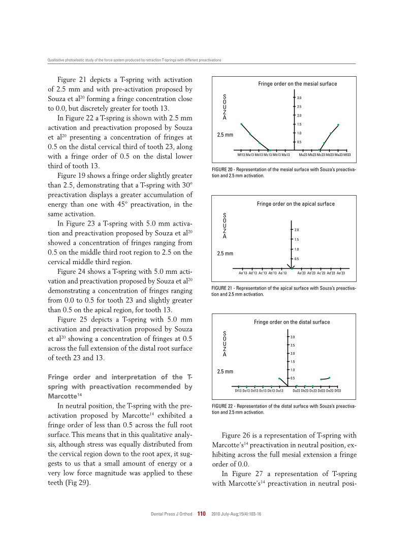
Figure 20 describes a T-spring with 2.5 mm acti-vation and preactivation proposed by Souza et al20
showing a concentration of fringes at 1.5, with the fringe order spread out in a symmetrical pattern.
Fringe order
Fringe order on the apical surface
FIGURE 13 - The green point in the vertex of the chart represents fringe order equal to zero.
FIGURE 14 - Representation of the mesial surface with Souza’s preactiva-tion in neutral position.
FIGURE 16 - Representation of the apical surface with Souza’s preactiva-tion in neutral position.
FIGURE 18 - Representation of the distal surface with Souza’s preactiva-tion in neutral position.
FIGURE 19 - T-spring activation at 5.0 mm (maximum activation).
0.5
1.0
1.5
2.0
0.5
1.0
1.5
2.5
2.0
3.0
0.0 mm
0.5
1.0
1.5
2.5
2.0
3.0
0.0 mm
0.0 mm0.5
1.0
1.5
2.5
2.0
3.0
tooth 13 tooth 23
Ae’13 Ad’13 Ac’13 Ab’13 Aa’13 Aa’23 Ab’23 Ac’23 Ad’23 Ae’23
S O U Z A
Mf13 Me13 Md13 Mc13 Mb13 Ma13 Ma23 Mb23 Mc23 Md23 Me23 Mf23
S O U Z A
Df13 De13 Dd13 Dc13 Db13 Da13 Da23 Db23 Dc23 Dd23 De23 Df23
S O U Z A
Qualitative photoelastic study of the force system produced by retraction T-springs with different preactivations
Dental Press J Orthod 110 2010 July-Aug;15(4):103-16
Fringe order on the apical surface
Fringe order on the distal surface
Fringe order on the mesial surface
FIGURE 20 - Representation of the mesial surface with Souza’s preactiva-tion and 2.5 mm activation.
FIGURE 21 - Representation of the apical surface with Souza’s preactiva-tion and 2.5 mm activation.
FIGURE 22 - Representation of the distal surface with Souza’s preactiva-tion and 2.5 mm activation.
2.5 mm0.5
1.0
1.5
2.0
2.5 mm0.5
1.0
1.5
2.5
2.0
3.0
2.5 mm0.5
1.0
1.5
2.5
2.0
3.0
Figure 26 is a representation of T-spring with Marcotte’s14 preactivation in neutral position, ex-hibiting across the full mesial extension a fringe order of 0.0.
In Figure 27 a representation of T-spring with Marcotte’s14 preactivation in neutral posi-
Figure 21 depicts a T-spring with activation of 2.5 mm and with pre-activation proposed by Souza et al20 forming a fringe concentration close to 0.0, but discretely greater for tooth 13.
In Figure 22 a T-spring is shown with 2.5 mm activation and preactivation proposed by Souza et al20 presenting a concentration of fringes at 0.5 on the distal cervical third of tooth 23, along with a fringe order of 0.5 on the distal lower third of tooth 13.
Figure 19 shows a fringe order slightly greater than 2.5, demonstrating that a T-spring with 30º preactivation displays a greater accumulation of energy than one with 45º preactivation, in the same activation.
In Figure 23 a T-spring with 5.0 mm activa-tion and preactivation proposed by Souza et al20 showed a concentration of fringes ranging from 0.5 on the middle third root region to 2.5 on the cervical middle third region.
Figure 24 shows a T-spring with 5.0 mm acti-vation and preactivation proposed by Souza et al20 demonstrating a concentration of fringes ranging from 0.0 to 0.5 for tooth 23 and slightly greater than 0.5 on the apical region, for tooth 13.
Figure 25 depicts a T-spring with 5.0 mm activation and preactivation proposed by Souza et al20 showing a concentration of fringes at 0.5 across the full extension of the distal root surface of teeth 23 and 13.
Fringe order and interpretation of the t-spring with preactivation recommended by Marcotte14
In neutral position, the T-spring with the pre-activation proposed by Marcotte14 exhibited a fringe order of less than 0.5 across the full root surface. This means that in this qualitative analy-sis, although stress was equally distributed from the cervical region down to the root apex, it sug-gests to us that a small amount of energy or a very low force magnitude was applied to these teeth (Fig 29).

Mf13 Me13 Md13 Mc13 Mb13 Ma13 Ma23 Mb23 Mc23 Md23 Me23 Mf23
S O U Z A
Af’13 Ae’13 Ad’13 Ac’13 Ab’13 Aa’13 Aa’23 Ab’23 Ac’23 Ad’23 Ae’23 Af’23
S O U Z A
Df13 De13 Dd13 Dc13 Db13 Da13 Da23 Db23 Dc23 Dd23 De23 Df23
S O U Z A
Mf13 Me13 Md13 Mc13 Mb13 Ma13 Ma23 Mb23 Mc23 Md23 Me23 Mf23
Ae’13 Ad’13 Ac’13 Ab’13 Aa’13 Aa’23 Ab’23 Ac’23 Ad’23 Ae’23
M A R C O T T E
M A R C O T T E
M A R C O T T E
De13 Dd13 Dc13 Db13 Da13 Da23 Db23 Dc23 Dd23 De23
Maia LGM, Gomes VL, Santos-Pinto A, Lopes I Jr, Gandini LG Jr
Dental Press J Orthod 111 2010 July-Aug;15(4):103-16
Fringe order on the mesial surface
Fringe order on the apical surface
Fringe order on the distal surface
FIGURE 25 - Representation of the distal surface with Souza’s preactiva-tion and 5.0 mm activation.
FIGURE 23 - Representation of the mesial surface with Souza’s preactiva-tion and 5.0 mm activation.
FIGURE 24 - Representation of the apical surface with Souza’s preactiva-tion and 5.0 mm activation.
5.0 mm0.5
1.0
1.5
2.5
2.0
3.0
5.0 mm0.5
1.0
1.5
2.5
2.0
3.0
5.0 mm0.5
1.0
1.5
2.5
2.0
3.0
tion, exhibiting across the full apical extension a fringe order of 0.0.
Figure 28 is the graphical representation of T-spring with Marcotte’s14 preactivation in neutral position, exhibiting across the full distal extension a fringe order of 0.0.
Fringe order on the mesial surface
Fringe order on the apical surface
Fringe order on the distal surface
Figure 30 shows a fringe order slightly smaller than 1.5, demonstrating that a T-spring with 45º preactivation displays a slightly smaller energy accumulation than one with 30º preactivation, when activated at 2.5 mm.
Figure 32 demonstrates a T-spring activated
FIGURE 26 - Representation of the mesial surface with Marcotte’s preac-tivation in neutral position
FIGURE 28 - Representation of the distal surface with Marcotte’s preacti-vation in neutral position.
FIGURE 27 - Representation of the apical surface with Marcotte’s preacti-vation in neutral position.
0.0 mm 0.5
1.0
1.5
2.5
2.0
3.0
0.5
1.0
1.5
2.0
0.0 mm
0.0 mm
1.0
0.5
1.5
2.0
Qualitative photoelastic study of the force system produced by retraction T-springs with different preactivations
Dental Press J Orthod 112 2010 July-Aug;15(4):103-16
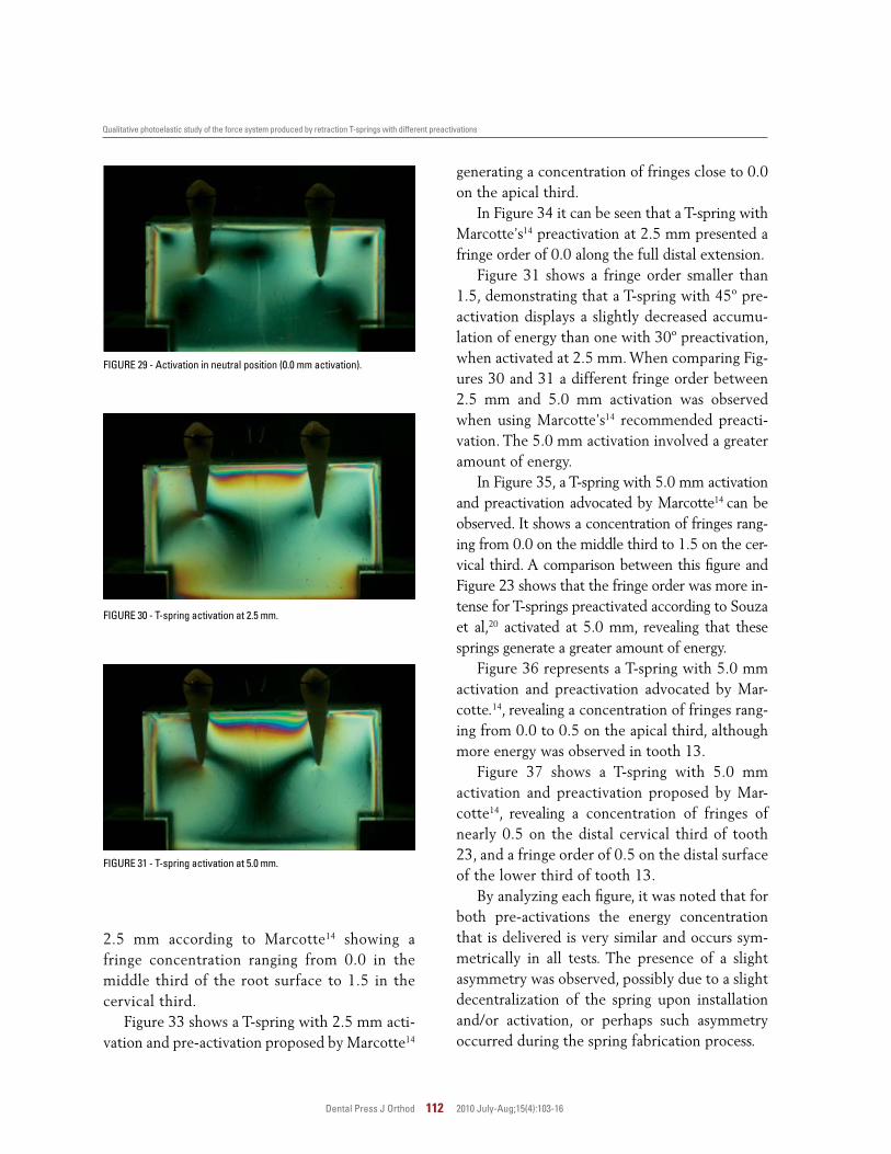
2.5 mm according to Marcotte14 showing a fringe concentration ranging from 0.0 in the middle third of the root surface to 1.5 in the cervical third.
Figure 33 shows a T-spring with 2.5 mm acti-vation and pre-activation proposed by Marcotte14
FIGURE 29 - Activation in neutral position (0.0 mm activation).
FIGURE 30 - T-spring activation at 2.5 mm.
FIGURE 31 - T-spring activation at 5.0 mm.
generating a concentration of fringes close to 0.0 on the apical third.
In Figure 34 it can be seen that a T-spring with Marcotte’s14 preactivation at 2.5 mm presented a fringe order of 0.0 along the full distal extension.
Figure 31 shows a fringe order smaller than 1.5, demonstrating that a T-spring with 45º pre-activation displays a slightly decreased accumu-lation of energy than one with 30º preactivation, when activated at 2.5 mm. When comparing Fig-ures 30 and 31 a different fringe order between 2.5 mm and 5.0 mm activation was observed when using Marcotte’s14 recommended preacti-vation. The 5.0 mm activation involved a greater amount of energy.
In Figure 35, a T-spring with 5.0 mm activation and preactivation advocated by Marcotte14 can be observed. It shows a concentration of fringes rang-ing from 0.0 on the middle third to 1.5 on the cer-vical third. A comparison between this figure and Figure 23 shows that the fringe order was more in-tense for T-springs preactivated according to Souza et al,20 activated at 5.0 mm, revealing that these springs generate a greater amount of energy.
Figure 36 represents a T-spring with 5.0 mm activation and preactivation advocated by Mar-cotte.14, revealing a concentration of fringes rang-ing from 0.0 to 0.5 on the apical third, although more energy was observed in tooth 13.
Figure 37 shows a T-spring with 5.0 mm activation and preactivation proposed by Mar-cotte14, revealing a concentration of fringes of nearly 0.5 on the distal cervical third of tooth 23, and a fringe order of 0.5 on the distal surface of the lower third of tooth 13.
By analyzing each figure, it was noted that for both pre-activations the energy concentration that is delivered is very similar and occurs sym-metrically in all tests. The presence of a slight asymmetry was observed, possibly due to a slight decentralization of the spring upon installation and/or activation, or perhaps such asymmetry occurred during the spring fabrication process.

Mf13 Me13 Md13 Mc13 Mb13 Ma13 Ma23 Mb23 Mc23 Md23 Me23 Mf23
Ae’13 Ad’13 Ac’13 Ab’13 Aa’13 Aa’23 Ab’23 Ac’23 Ad’23 Ae’23
M A R C O T T E
M A R C O T T E
Df13 De13 Dd13 Dc13 Db13 Da13 Da23 Db23 Dc23 Dd23 De23 Df23
M A R C O T T E
Mf13 Me13 Md13 Mc13 Mb13 Ma13 Ma23 Mb23 Mc23 Md23 Me23 Mf23
M A R C O T T E
M A R C O T T E
Af’13 Ae’13 Ad’13 Ac’13 Ab’13 Aa’13 Aa’23 Ab’23 Ac’23 Ad’23 Ae’23 Af’23
M A R C O T T E
De13Df13 Dd13 Dc13 Db13 Da13 Da23 Db23 Dc23 Dd23 De23 Df23
Maia LGM, Gomes VL, Santos-Pinto A, Lopes I Jr, Gandini LG Jr
Dental Press J Orthod 113 2010 July-Aug;15(4):103-16
Fringe order on the apical surface
Fringe order on the mesial surface
Fringe order on the distal surface
FIGURE 33 - Representation of the apical surface with Marcotte’s preacti-vation and 2.5 mm activation
FIGURE 32 - Representation of the mesial surface with Marcotte’s preac-tivation and 2.5 mm activation.
FIGURE 34 - Representation of the distal surface with Marcotte’s preacti-vation and 2.5 mm activation.
Fringe order on the mesial surface
Fringe order on the apical surface
Fringe order on the distal surface
dIScuSSIOnSpace closure in orthodontics should be
performed as required in each particular case.2,3,4,6,11,13,14,17-24 An appropriate choice of mechanism requires in-depth knowledge of the biomechanics built into the different retraction
FIGURE 35 - Representation of the mesial surface with Marcotte’s preacti-vation and 5.0 mm activation.
FIGURE 36 - Representation of the apical surface with Marcotte’s preacti-vation and 5.0 mm activation.
FIGURE 37 - Representation of the distal surface with Marcotte’s preacti-vation and 5.0 mm activation.
devices as well as the force systems they deliver. To this end, space closing springs should deliver a low load/deflection rate and a high momen-tum/force ratio, thereby enabling adequate tooth movement control.
The purpose of this study was to evaluate, us-
0.5
1.0
1.5
2.5
2.0
3.0
0.5
1.0
1.5
2.0
2.5 mm
2.5 mm0.5
1.0
1.5
2.5
2.0
3.0
2.5 mm 0.5
1.0
1.5
2.5
2.0
3.0
5.0 mm
5.0 mm0.5
1.0
1.5
2.5
2.0
3.0
5.0 mm0.5
1.0
1.5
2.5
2.0
3.0
Qualitative photoelastic study of the force system produced by retraction T-springs with different preactivations
Dental Press J Orthod 114 2010 July-Aug;15(4):103-16
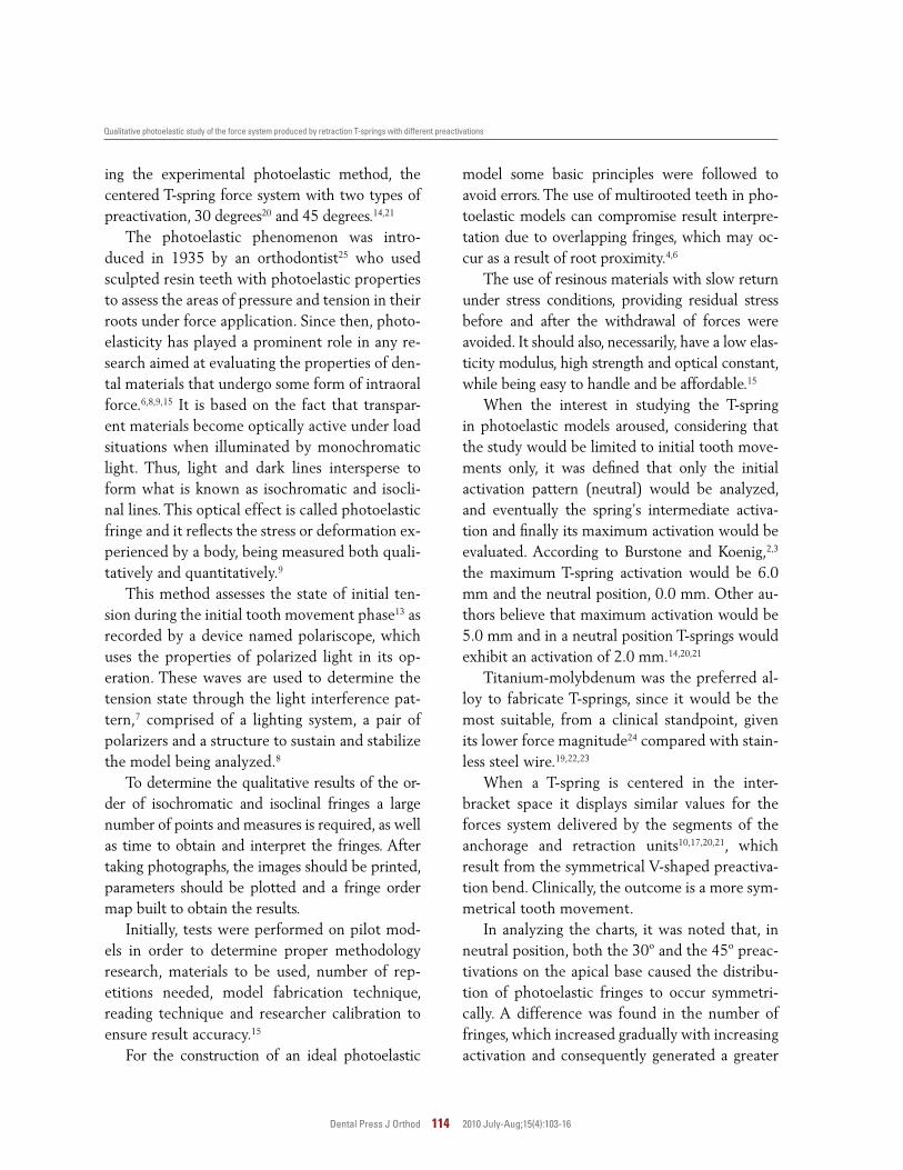
ing the experimental photoelastic method, the centered T-spring force system with two types of preactivation, 30 degrees20 and 45 degrees.14,21
The photoelastic phenomenon was intro-duced in 1935 by an orthodontist25 who used sculpted resin teeth with photoelastic properties to assess the areas of pressure and tension in their roots under force application. Since then, photo-elasticity has played a prominent role in any re-search aimed at evaluating the properties of den-tal materials that undergo some form of intraoral force.6,8,9,15 It is based on the fact that transpar-ent materials become optically active under load situations when illuminated by monochromatic light. Thus, light and dark lines intersperse to form what is known as isochromatic and isocli-nal lines. This optical effect is called photoelastic fringe and it reflects the stress or deformation ex-perienced by a body, being measured both quali-tatively and quantitatively.9
This method assesses the state of initial ten-sion during the initial tooth movement phase13 as recorded by a device named polariscope, which uses the properties of polarized light in its op-eration. These waves are used to determine the tension state through the light interference pat-tern,7 comprised of a lighting system, a pair of polarizers and a structure to sustain and stabilize the model being analyzed.8
To determine the qualitative results of the or-der of isochromatic and isoclinal fringes a large number of points and measures is required, as well as time to obtain and interpret the fringes. After taking photographs, the images should be printed, parameters should be plotted and a fringe order map built to obtain the results.
Initially, tests were performed on pilot mod-els in order to determine proper methodology research, materials to be used, number of rep-etitions needed, model fabrication technique, reading technique and researcher calibration to ensure result accuracy.15
For the construction of an ideal photoelastic
model some basic principles were followed to avoid errors. The use of multirooted teeth in pho-toelastic models can compromise result interpre-tation due to overlapping fringes, which may oc-cur as a result of root proximity.4,6
The use of resinous materials with slow return under stress conditions, providing residual stress before and after the withdrawal of forces were avoided. It should also, necessarily, have a low elas-ticity modulus, high strength and optical constant, while being easy to handle and be affordable.15
When the interest in studying the T-spring in photoelastic models aroused, considering that the study would be limited to initial tooth move-ments only, it was defined that only the initial activation pattern (neutral) would be analyzed, and eventually the spring’s intermediate activa-tion and finally its maximum activation would be evaluated. According to Burstone and Koenig,2,3 the maximum T-spring activation would be 6.0 mm and the neutral position, 0.0 mm. Other au-thors believe that maximum activation would be 5.0 mm and in a neutral position T-springs would exhibit an activation of 2.0 mm.14,20,21
Titanium-molybdenum was the preferred al-loy to fabricate T-springs, since it would be the most suitable, from a clinical standpoint, given its lower force magnitude24 compared with stain-less steel wire.19,22,23
When a T-spring is centered in the inter-bracket space it displays similar values for the forces system delivered by the segments of the anchorage and retraction units10,17,20,21, which result from the symmetrical V-shaped preactiva-tion bend. Clinically, the outcome is a more sym-metrical tooth movement.
In analyzing the charts, it was noted that, in neutral position, both the 30º and the 45º preac-tivations on the apical base caused the distribu-tion of photoelastic fringes to occur symmetri-cally. A difference was found in the number of fringes, which increased gradually with increasing activation and consequently generated a greater
Maia LGM, Gomes VL, Santos-Pinto A, Lopes I Jr, Gandini LG Jr
Dental Press J Orthod 115 2010 July-Aug;15(4):103-16
force magnitude. By comparing force magnitude between the two preactivations (Figs 23 and 35), it is clear that the greatest magnitude occurred in the 30º preactivation.
The position of the T-spring in the inter-bracket space and the amount of activation are directly linked to the type of movement pro-duced by the spring. When the T-spring is ac-tivated at 5.0 mm, the M/F ratio is 7.6, which provides a controlled tipping movement be-cause its center of rotation is positioned more apically.3 After 1.0 mm of deactivation, the M/F ratio is 9.1, which causes teeth to move by translation. Should this deactivation persist, tooth movement will occur by root movement3 and at this time the spring should be reactivated to avoid contact between the roots of teeth ad-jacent to dental extractions.
In this experimental study, which used photo-elastic models, we observed a higher concentra-tion of photoelastic fringes in the cervical mesial region and no fringes on the distal apical region, at maximum activation of both springs. As de-activation occurred, this fringe order decreased in the cervical mesial region and increased in the mesial apical region until the fringe order reached higher energy concentration in the me-sial apical region and lower concentration in the cervical mesial and distal apical regions. In light of these qualitative features, we can deduce that at maximum activation the springs exhibited a tendency toward root movement at 0.0 mm activation, bodily movement at medium acti-vation and ultimately, at maximum activation,
controlled tipping movement.An analysis of Figures 14, 21, 22, 33, 36 and
37 showed that fringe orders lower than 0.5 were formed. Some asymmetry, observed in Figures 14, 20, 21, 22, 24, 33, 36 and 37, showed no sig-nificant values. Importantly, these asymmetries may be due to an eccentricity in the position of the T-spring or an asymmetry in its final design.
It is also noteworthy that the force system de-livered in all test groups was symmetrical for both teeth (13 and 23). The results are consistent with those observed in mechanical tests,3,11,19,20,21,23,24 which were strikingly similar.
cOncLuSIOnSAfter implementing the experimental pho-
toelastic method for qualitative analysis of the force system delivered by centered T-springs made with 0.017 X 0.025-in TMA wire, we concluded that:
1. The tension state in all root surface for the T-spring with preactivation according to Souza et al20 was slightly greater when com-pared to the T-spring with preactivation accord-ing to Marcotte14.
2. With 2.5 mm or 5.0 mm activation, the fringe order exhibited a tendency toward con-trolled tipping movement.
3. The fringe order was not much different at 2.5 mm activation with 30° and 45° preacti-vations.
4. At 5.0 mm activation, the concentration of energy or force was clearly higher in both preac-tivations.
Qualitative photoelastic study of the force system produced by retraction T-springs with different preactivations
Dental Press J Orthod 116 2010 July-Aug;15(4):103-16
1. ArticoloLC,KusyK,SaundersCR,KusyRP.Influenceofceramicand stainless steel brackets on the notching of archwires during clinical treatment. Eur J Orthod. 2000 Aug;22(4):409-25.
2. Burstone CJ. The segmented arch approach to space closure. Am J Orthod. 1982 Nov;82(5):361-78.
3. Burstone CJ, Koenig HA. Optimizing anterior and canine retraction. Am J Orthod. 1976 Jul;70(1):1-19.
4. Burstone CJ, Pryputniewicz RJ. Holographic determination of centers of rotation produced by orthodontic forces. Am J Orthod. 1980 Apr;77(4):396-409.
5. Chaconas SJ, Caputo AA, Davis JC. The effects of orthopedic forces on the craniofacial complex utilizing cervical and headgear appliance. Am J Orthod. 1976 May;69(5):527-39.
6. Chaconas SJ, Caputo AA, Miyashita K. Force distribution comparisons of various retraction archwires. Angle Orthod. 1989 May;59(1):25-30.
7. Dally JW, Rilley WF. Experimental stress analysis. New York: McGrall-Hill; 1965.
8. Glickman I, Roeber FW, Brion M, Pameijer JHN. Photoelastic analysis of internal stresses in the periodontium created by occlusal forces. J Periodontol. 1970 Jan;41(1):30-5.
9. Haraldson T. Photoelastic study of some biomechanical factors affecting the anchorage of osseointegrated implants in the jaw. Scand J Plast Reconstr Surg. 1980;14(3):209-14.
10. Hoenigl KD, Freudenthaler J, Marcotte MR, Bantleon HP. The centered T-loop: a new way of preactivation. Am J Orthod Dentofacial Orthop. 1995 Aug;108(2):149-53.
11. Kuhlberg AJ, Burstone CJ. T-loop position and anchorage control. Am J Orthod Dentofacial Orthop. 1997 Jul;112(1):12-8.
12. Kusy RP, Whitley JQ. Friction between different wire-bracket configurationsandmaterials.SeminOrthod.1997;3(3):166-77.
13. Lotti RS, Mazzieiro ET, Landre J Jr.Ainfluênciadoposicionamentoda alça T segmentada durante o movimento de retração inicial. Umaavaliaçãopelométododoselementosfinitos.RevDentalPress Ortod Ortop Facial. 2006 maio-jun;11(3):41-54.
14. Marcotte MR. Biomecânica em Ortodontia. São Paulo: Ed. Santos; 1993.
REFEREncES
15. Oliveira EJ. Material e técnica para análise fotoelástica plana da distribuição de tensões produzidas por implantes odontológicos. [dissertação]. Uberlândia (MG). Universidade Federal de Uberlândia; 2003.
16. Reitan K. Continuous bodily tooth movement and its histological significance.ActaOdontolScand.1947;7:115-44.
17. Shimizu RH. Fechamento de espaços após exodontias de primeiros pré-molares. [dissertação]. Araraquara (SP). Universidade Estadual Paulista; 1995.
18. Shimizu RH. Estudo dos sistemas de forças gerados pelas alças ortodônticas para fechamento de espaços. [tese]. Araraquara (SP). Universidade Estadual Paulista; 1999.
19. Shimisu RH, Sakima T, Santos-Pinto A, Shimizu IA. Desempenho biomecânicodaalça“T”,construídacomfiodeaçoinoxidável,durante o fechamento de espaços no tratamento ortodôntico. Rev Dental Press Ortod Ortop Facial. 2002 nov-dez;7(6):49-61.
20. Souza RS, Santos-Pinto A, Shimizu RI, Sakima MT, Gandini LG Jr. Avaliação do sistema de forças gerado pela alça T de retração, pré-ativada segundo o padrão UNESP-Araraquara. Rev Dental Press Ortod Ortop Facial. 2003 set-out;8(5):113-22.
21. Souza RS, Shimizu RI, Sakima MT, Santos-Pinto A, GandinI LG Jr. Avaliação do sistema de forças gerado pela alça T de retração pré-ativada segundo o padrão Marcotte. JBO: J Bras Ortod Ortop Facial. 2005;10(55):50-8.
22. Thiesen G, Rego MVNN, Menezes LM, Shimizu RH. Avaliação biomecânica de diferentes alças ortodônticas de fechamento de espaços confeccionadas com aço inoxidável. Rev Assoc Paul Especial Ortod Ortop Facial. 2004 abr-jun;2(2):77-92.
23. THiesen G, Rego MVN, Menezes LM. A pré-ativação de alças ortodônticas para fechamento de espaços e seu efeito no sistema de forças gerado. Ortodontia Gaúcha. 2004 jan-jun;8(1):42-59.
24. Thiesen G, Rego MVNN, Menezes LM, Shimizu RH. A utilização dediferentesconfiguraçõesdemolasTparaobtençãodesistemas de forças otimizados. Rev Dental Press Ortod Ortop Facial. 2006 set-out;11(5):57-77.
25. Zak B. Photoelastiche analyse in der orthodontischen mechanik. Z Stomatol. 1935;33:22-37.
contact addressLuiz Guilherme Martins MaiaRua Terêncio Sampaio, 309CEP: 49.025-700 – Aracaju / SE, BrazilE-mail: [email protected]
Submitted: September 2007Revised and accepted: November 2008

![20.310J Molecular, Cellular, and Tissue Biomechanics ... · Qualitative picture of the origin of the trapping force. [a] Lateral gradient force of a Gaussian laser beam profile. Since](https://img.pdfslide.us/doc/110x75/5ff30d663817d45d9646ca20/20310j-molecular-cellular-and-tissue-biomechanics-qualitative-picture-of.jpg)