Embed Size (px)
Citation preview
Qualitative and Quantitative Mechanical AssemblyDesign
Leo JoskowiczInstitute of Computer Science
The Hebrew UniversityJerusalem 91904, Israel
E-mail : josko@cs .huji .ac .il '
Abstract
We describe a unified approach to computer-aided mechanical assembly design in which alldesign tasks are performed within a single com-putational paradigm supported by integrated de-sign software . We have developed a prototypedesign environment for planar assemblies, calledHIPAIR, that supports diverse design tasks . Weorganize the design tasks around the fundamen-tal task of contact, analysis, which we automateby configuration space computation . Configura-tion space is a complete, concise representation ofrigid body interactions that contains the requisitequalitative and quantitative contact informationfor all design tasks . We describe practical algo-rithms for the key tasks of dynamical simulationand kinematic tolerancing . HIPAIR allows de-signers to perform computations that lie outsidethe scope of previous software and that defy man-ual analysis . It computes qualitative and quan-titative functional changes, allowing designers tostudy assembly function under a range of operat-ing conditions, to find and correct design flaws,and to evaluate the functional effects of part tol-erances . HIPAIR has been tested on hundreds ofpairs and on a dozen assemblies . It performs atinteractive speed on assemblies of ten parts withtens of thousands of contacts .
IntroductionWe describe a unified approach to computer-aided me-chanical assembly design in which all design tasks areperformed within a single computational paradigmsupported by integrated design software . Mechanicalassembly design is the task of devising an assemblyof parts that performs a function reliably and eco-nomically . It. i s a ubiquitous activity that. spans me-chanical, electrical . and biomedical engineering . De-signers need to devise, analyze, and compare com-
1-VWW site : http://www .cs .huji.ac .il/vjosko/cad .htm i
Elisha SacksComputer Science Department
Purdue UniversityWest Lafayette, IN 47907, USAE-mail : epsC@cs .purdue.edu
peting design prototypes to produce optimal designs .Computer-aided design reduces design time and im-proves quality by allowing designers to substitute elec-tronic prototypes for physical prototypes in diversetasks .
Reasoning about part contacts plays a central rolein mechanical assembly design . Contacts are the phys-ical primitives that make assemblies out of collectionsof parts . Assemblies perform functions by transform-ing motions via part contacts . The shapes of the inter-acting parts impose constraints on their motions . Forexample, a door rotates about its hinges and meshedgears rotate in unison . Contact constraints largelydetermine the function of assemblies . Designers com-pute contact constraints to validate function and tomeasure performance . They correct design flaws bymodifying part contacts . They choose part tolerancesbased on the variation in assembly function that theyproduce .
Contact analysis, also called kinematic analysis, de-termines the qualitative and quantitative relation be-tween the function of an assembly and the shapes andmotions of its parts . The primary qualitative infor-mation is the interacting parts, the touching features,and the configurations where these change . Designtasks require specialized qualitative information, suchas jamming and failure modes for validation, impactsand sticking for simulation, and dependencies betweenpart parameters and function variation for toleranc-ing . The primary quantitative information is the legalassembly configurations and the compliant motions incontact configurations . The specialized informationquantifies the qualitative information with jammingconfigurations, impact forces . and function variations .
Contact analysis is difficult and time-consumingeven for experienced designers due to the quantity andcomplexity of the contact constraints . Designers needto ensure that the intended contacts occur, to derivetheir constraints, and to guarantee that unintendedcontacts cannot occur . The difficulty is greatest inassemblies with multiple contacts, meaning that dif-ferent parts or part features interact at various stages
r CAD SYSTEM
part
degrees ofshapes freedom
122
initialconfiguration
of the work cycle . Manual analysis of these assem-blies is error-prone and time-consuming at best andis often infeasible . Multiple contacts pervade modernmechanisms and account for 65% of the 2500 mecha-nisms in Artobolevsky's encyclopedia (Joskowicz andSacks, 1991) . The most common examples are gears,cams, clutches, and ratchets . Designers analyze mul-tiple contacts when testing for part interference, jam-ming, cam under-cutting, and gear backlash . In kine-matic tolerance analysis, designers study part varia-tions that introduce multiple contacts into assemblieswhose nominal function has permanent contacts, suchas joint play in linkages .
Previous research in mechanical engineering, graph-ics, robotics, and artificial intelligence does not pro-vide general algorithms for contact analysis . Mechan-ical simulation research (Haug, 1989 ; Schiehlen, 1990)focuses on efficient methods of solving the contactconstraints of permanent contact assemblies, such aslinkages and manipulators . Research in gear design(Litvin, 1994) and in cam design (Gonzales-Palaciosand Angeles, 1993) addresses narrow classes of con-tacts . Assembly planning research (de Mello andLee, 1991) focuses on the combinatorics of sequenc-ing assembly steps for simple part shapes and mo-tions . Graphics research id physically based modeling(Baraff, 1992; Crerner and Stewart, 1989; Mirtich andCanny, 1995) provides fast collision detection algo-rithms for polyhedral objects, but does not addressthe other aspects of contact analysis in mechanicaldesign . Robotics research (Latombe, 1991) studiescontact analysis in the context of robot motion plan-ning . The planners use a configuration space repre-
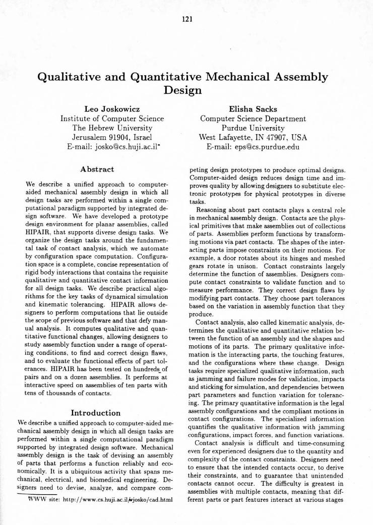
Figure 1 : HIPAIR mechanical design environment .
GRAPHICSAND
INTERACTION
J
sentation for the possible contacts between the robotand the obstacles, and search this space for collision-free paths . Most research addresses a single polyhe-dral robot moving amidst fixed polyhedral obstacles .It does not provide practical algorithms for curvedshapes or for multiple moving parts, which are thenorm in mechanical assemblies . Qualitative reason-ing research studies contact analysis for the task ofproducing symbolic, qualitative explanations of theworkings of mechanisms . Faltings (Faltings, 1990 ;Faltings, 1992), Forbus et al . (Forbus et al., 1991),and Joskowicz and Sacks (Joskowicz and Sacks, 1991)use the configuration space representation to derivequalitative descriptions of assembly contacts and kine-matics . The programs handle assemblies of planarparts with one degree of freedom and multiple con-tacts . We build on this work, extending it to generalplanar assemblies and to tolerancing and dynamicalsimulation .We have developed a unified approach to contact
analysis and to computer-aided assembly design basedon configuration space computation . In previouswork, we have shown that configuration space is acomplete, concise representation of rigid body interac-tion . We have demonstrated that performing contactanalysis on an assembly is equivalent to computing itsconfiguration space . The configuration space containsthe requisite qualitative and quantitative informationfor design tasks involving contacts . It models perma-nent and multiple contacts uniformly.
In this paper, we survey our recent work on HIPAIRwith an emphasis on the qualitative reasoning aspects .Figure 1 summarizes our approach . The core mod-
ule automates contact analysis via configuration spacecomputation . The task modules use the configurationspaces to support reasoning about contacts . We haveimplemented a prototype design environment for pla-nar assemblies, called HIPAIR, based on this model.It automates dynamical simulation and provides novelsupport for validation, tolerancing, and parametricdesign . HIPAIR allows designers to perform compu-tations that lie outside the scope of previous softwareand that defy manual analysis . It allows them to vi-sualize assembly function under a range of operatingconditions . to find and correct design flaws, and toevaluate the functional effects of part tolerances . Wehave tested HIPAIR on hundreds of pairs and on adozen assemblies with up to ten moving parts . Wecan analyze assemblies with thousands of contacts ina few seconds on a workstation . The running times inthe paper are for a Silicon Graphics Indigo 2 worksta-tion with 64MB of main memory and a 250 Mhz pro-cessor . All the figures in the paper are direct HIPAIRoutput .
Configuration spaceThe configuration space of an assembly of parts is aparameter space whose points (tuples of parametervalues) specify the spatial configurations (positionsand orientations) of the parts . The parameters repre-sent translations and rotations of parts with respectto a fixed global coordinate system . For example, agear pair has a two-dimensional configuration spacein which each gear configuration is specified by a ro-tation parameter . The configuration space dimensionequals the total number of degrees of freedom of theparts in the assembly .
Configuration space partitions into free space wherethe parts do not touch and into blocked space wheresome parts overlap . The common boundary, calledcontact space, contains the configurations where someparts touch without overlap and the rest do not touch .Only free space and contact space are physically real-izable . Free space represents the realizable motions ofthe parts and contact space represents the couplingsbetween their motions induced by contacts .We illustrate these concepts on a Geneva pair (Fig-
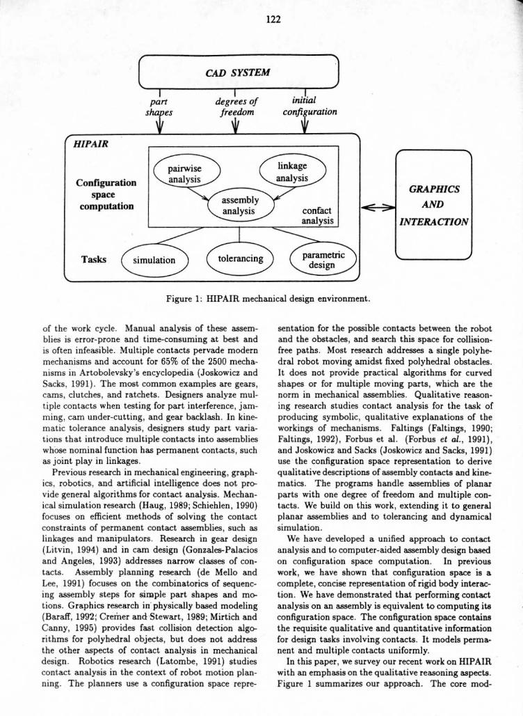
ure 2) . The driver consists of a driving pin and a lock-ing arc segment mounted on a cylindrical base (notshown) . The wheel consists of four locking arc seg-ments and four slots . The driver rotates around axisOd and the wheel rotates : around axis Ou, . Each ro-tation of the driver causes a nonuniform, intermittentrotation of the whe6l with four drive periods where thedriver pin engages the wheel slots and with four dwellperiods where the driver locking segment engages thewheel locking segments .The configuration space of the Geneva pair is two-
dimensional with coordinates the orientations 0 and wof the driver and the wheel . The shaded region is the
123
wheel driver
_)e71
Figure 2 : Geneva pair and its configuration space .The pair is displayed in configuration 0 = 0, w = 0,marked by the dot at the configuration space origin .
blocked space where the driver and the wheel over-lap . The white region is the free space . It forms asingle channel that wraps around the horizontal andvertical boundaries, since the configurations at fir co-incide . The width of the channel measures the poten-tial backlash of the pair . The curves that bound thefree and blocked regions, called contact curves, formthe contact space . The functional forms of the con-tact curves encode the contact relations between thewheel and the driver . The horizontal segments repre-sent contacts between the locking arc segments, whichhold the wheel stationary. The diagonal segments rep-resent contacts between the pin and the slots, whichrotate the wheel . The ranges of the contact curvesexpress the contact conditions ; contact changes occurat curve endpoints .
Configuration space encodes in a uniform geometricframework the quantitative and qualitative informa-tion for reasoning about part contact in all mechanicalassemblies . It represents all the motion constraints in-duced by part contacts and the configurations wherecontacts change . It specifies the space of kinematicfunctions under all external forces, and thus consti-tutes global representation for contact analysis . Thefunctions under specific forces are paths in configura-tion space that consist of contact and free segmentsseparated by contact change configurations . For ex-ample, clockwise rotation of the driver produces apath that follows the contact curves on the bottom ofthe free space from right to left . The kinematic func-tion consists of horizontal segments alternating withdiagonal segments . The pin makes contact with theslot at the start of the diagonal segments and breakscontact at the end .The configuration space of an assembly is compo-
sitional : it is determined by the configuration spacesof its pairs of parts (Joskowicz and Sacks, 1991) . Al-though general configuration space computation is in-tractable in the worst case, it is manageable in prac-tice because mechanical assemblies have characteris-tics that distinguish them from arbitrary collectionsof parts .We have developed fast, robust configuration space
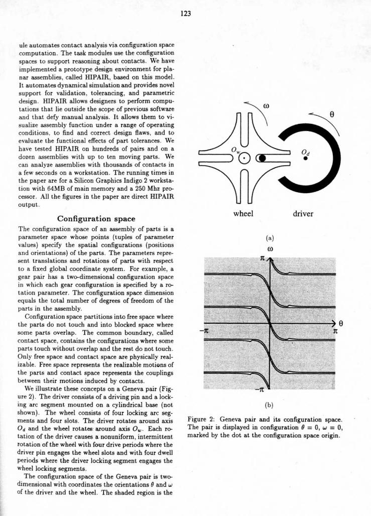
computation programs for planar pairs with two de-grees of freedom (Sacks and Joskowicz, 1995) and forgeneral planar pairs (Sacks and Bajaj, 1997) (Figure 3 .The planar algorithm is 100 times faster than the gen-eral algorithm (seconds versus milliseconds) . The sav-ings is important because 90% of assemblies are planarbased on our survey of 2500 mechanisms (Joskowiczand Sacks, 1991) and on an informal survey of modernmechanisms, such as VCR's and photocopiers .
Kinematic tolerance analysisThe goal of tolerance analysis is to compute the vari-ation in the function of mechanical assemblies re-sulting from manufacturing variation in the shapes
pin joint
Figure 3 : Movie camera film advance . The driver camrotates about a shaft on the frame, while the enclos-ing follower is attached to the frame by a pin joint .As the cam rotates clockwise, the follower tip engagesthe film (not shown), pushes it down one frame, andretracts . (a) driver cam at configuration is (0, 0, BA)and follower at configuration is (XB,YB,BB) . (b) con-figuration space .
arc -span -------- --___F -
,~ arc-origin-radiusarc-origin-angular-
and configurations of their parts . Kinematic toler-ance analysis computes the qualitative and quantita-tive variations of the kinematic function determinedby the series of contact constraints over the assem-bly work cycle . For example, a meshed pair of rotat-ing gears undergoes a series of tooth contacts thatimpose a relation between the gear angular veloci-ties . Ideal gears transmit rotation linearly, whereasreal gears exhibit backlash and chatter because of axismisalignment and gear profile imperfections . Design-ers use kinematic tolerance analysis to guarantee cor-rect assembly function and to reduce manufacturingcost . Worst-case analysis derives guaranteed upperand lower bounds on the variation, while statisticalanalysis derives probabilistic bounds . The analysiscomplements tolerancing for assembly, which verifiesthat. the parts can be assembled despite shape varia-tions .
Tolerance specifications define the allowable varia-tion in the shape and configurations of the parts ofan assembly . The most common are parametric andgeometric specifications (Voelcker, 1993) . Parametricspecifications restrict the parameters of the assemblymodel to intervals of values . For example, a toler-ance of r = 1 ± 0.1 restricts the radius r of a disk tothe interval [0 .9, 1 .1] . Geometric specifications restrictpart features to zones around the nominal features,typically to fixed-width bands, called uniform profiletolerance zones, whose boundaries are the geometricinset and offset of the nominal features . For example,a uniform geometric profile tolerance of 0.1 on a diskof radius 1 constrains its surface to lie inside an an-nulus with outer radius 1 .1 and inner radius 0 .9 . Wediscuss parametric tolerances because they are bestsuited to kinematic tolerance analysis . We analyzegeometric tolerances by translating them into para-
125
rotation-center-offset-xrotation-center-offset-
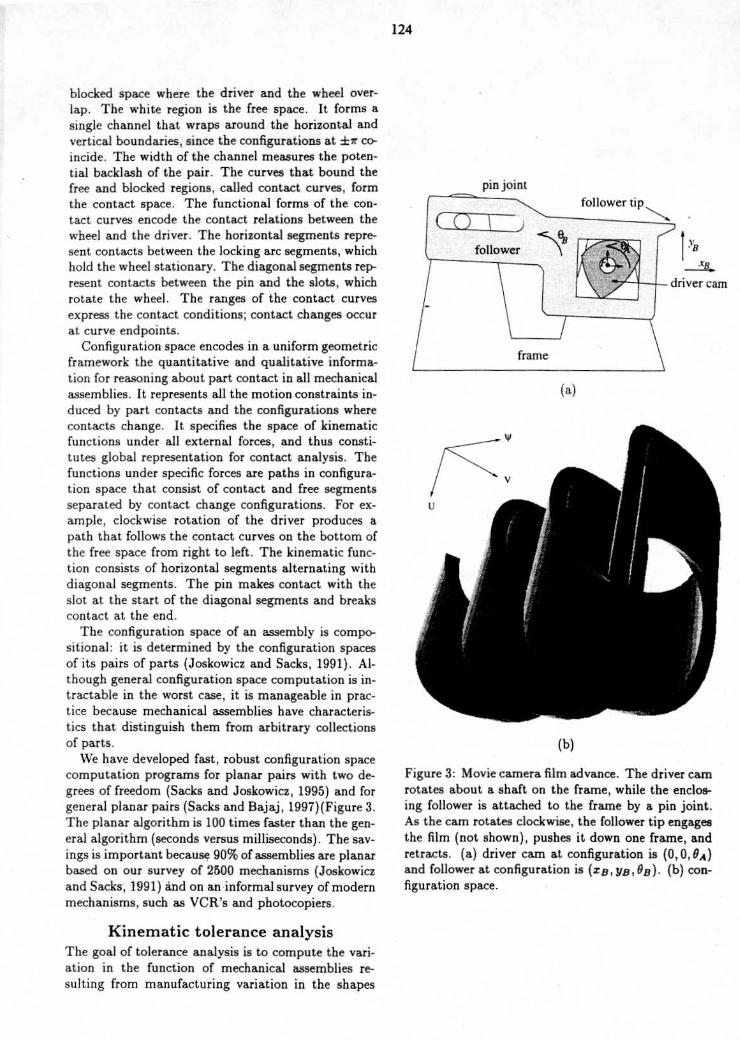
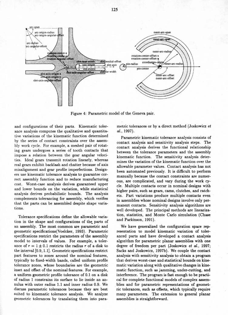
Figure 4 : Parametric model of the Geneva pair .
outer-arc-span
metric tolerances or by a direct method (Joskowicz etal., 1997) .
Parametric kinematic tolerance analysis consists ofcontact analysis and sensitivity analysis steps . Thecontact analysis derives the functional relationshipbetween the tolerance parameters and the assemblykinematic function . The sensitivity analysis deter-mines the variation of the kinematic function over theallowable parameter values . Contact analysis has notbeen automated previously . It is difficult to performmanually because the contact constraints are numer-ous, are complicated, and vary during the work cy-cle . Multiple contacts occur in nominal designs withhigher pairs, such as gears, cams, clutches, and ratch-ets . Part variations produce multiple contacts evenin assemblies whose nominal designs involve only per-manent contacts . Sensitivity analysis algorithms arewell developed . The principal methods are lineariza-tion, statistics, and Monte Carlo simulation (Chaseand Parkinson, 1991) .
We have generalized the configuration space rep-resentation to model kinematic variation of toler-anced parts and have developed a contact analysisalgorithm for parametric planar assemblies with onedegree of freedom per part (Joskowicz et al., 1997 ;Sacks and Joskowicz, 1997b) . We couple the contactanalysis with sensitivity analysis to obtain a programthat derives worst-case and statistical bounds on kine-matic variation along with qualitative changes in kine-matic function, such as jamming, under-cutting, andinterference . The program is fast enough to be practi-cal for complete functional models of complex assem-blies and for parametric representations of geomet-ric tolerances, such as offsets, which typically requiremany parameters . The extension to general planarassemblies is straightforward .
Worst-case analysis of pairs
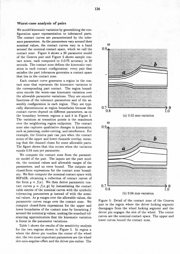
We model kinematic variation by generalizing the con-figuration space representation to toleranced parts .The contact curves are parameterized by the toler-ance parameters . As the parameters vary around theirnominal values, the contact curves vary in a bandaround the nominal contact space, which we call thecontact zone . Figure 4 shows a 26 parameter modelof the Geneva pair and Figure 5 shows sample con-tact zones, each computed to 0.01% accuracy in 20seconds . The contact zone defines the kinematic vari-ation in each contact configuration : every pair thatsatisfies the part tolerances generates a contact spacethat lies in the contact zone .
Each contact curve generates a region in the con-tact zone that represents the kinematic variation inthe corresponding part contact . The region bound-aries encode the worst-case kinematic variation overthe allowable parameter variations . They are smoothfunctions of the tolerance parameters and of the as-sembly configuration in each region . They are typi-cally discontinuous at region boundaries because thecontact curves depend on different parameters, as onthe boundary between regions a and b in Figure 5 .The variation at transition points is the maximumover the neighboring region endpoints . The contactzone also captures qualitative changes in kinematics,such as jamming, under-cutting, and interference . Forexample, the Geneva pair can jam when the contactzones of the upper and lower channels overlap, mean-ing that the channel closes for some allowable parts .The figure shows that this occurs when the variationequals 0 .04 rnm per parameter .We compute the contact zone from the paramet-
ric model of the pair . The inputs are the part mod-els, the nominal values and allowable ranges of theparameters, and an error bound . The outputs areclosed-form expressions for the contact zone bound-ary . We first compute the nominal contact space withHIPAIR, obtaining a collection of contact curves ofthe form y = f(x) . We then derive parametric con-tact curves y = f(x,p) by instantiating the contacttable entries of the nominal curves with the symbolictolerancing parameters p instead of with the nomi-nal values . As p ranges over the allowable values, theparametric curves range over the contact zone . Wecompute closed-form expressions for the upper andlower boundaries of the contact zone by linearizing faround the nominal p values, making the standard tol-erancing approximation that the kinematic variationis linear in the parameter variations .
Table 1 shows the results of the sensitivity analysisfor the two regions shown in Figure 5 . In region awhere the driver pin touches the corner of the wheelslot . the two most important parameters are the wheelslot-axis-angular-offset and the driver pin-radius . The
126
0.9.t,
0.7 L-0.8
(a) 0.02 mm variation
(b) 0.04 mm variation
Figure 5 : Detail of the contact zone of the Genevapair in the region where the driver locking segmentdisengages from the wheel locking segment and thedriver pin engages the slot of the wheel . The centercurves are the nominal contact space . The upper andlower curves bound the contact zone .
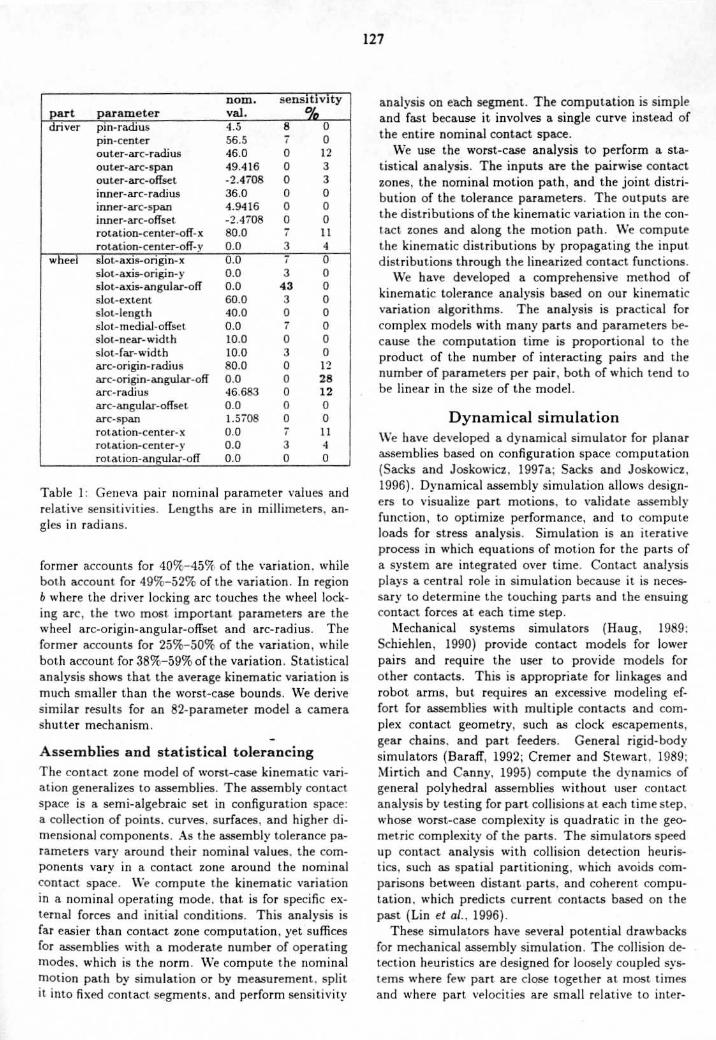
Table 1 : Geneva pair nominal parameter values andrelative sensitivities . Lengths are in millimeters, an-gles in radians .
former accounts for 401X-4517(, of the variation, whileboth account for 49%,-52% of the variation . In region6 where the driver locking arc touches the wheel lock-ing arc, the two most important parameters are thewheel arc-origin-angular-offset and arc-radius . Theformer accounts for 25%-50% of the variation, whileboth account for 38%-59% of the variation . Statisticalanalysis shows that the average kinematic variation ismuch smaller than the worst-case bounds . We derivesimilar results for an 82-parameter model a camerashutter mechanism .
Assemblies and statistical tolerancingThe contact zone model of worst-case kinematic vari-ation generalizes to assemblies . The assembly contactspace is a semi-algebraic set in configuration space :a collection of points . curves . surfaces, and higher di-mensional components . As the assembly tolerance pa-rameters vary around their nominal values, the com-ponents vary in a contact zone around the nominalcontact space . We compute the kinematic variationin a nominal operating mode, that is for specific ex-ternal forces and initial conditions . This analvsis isfar easier than contact zone computation, yet sufficesfor assemblies with a moderate number of operatingmodes, which is the norm . We compute the nominalmotion path by simulation or by measurement . splitit into fixed contact. segments, and perform sensitivity
12 7
analysis on each segment . The computation is simpleand fast because it involves a single curve instead ofthe entire nominal contact space .We use the worst-case analysis to perform a sta-
tistical analysis . The inputs are the pairwise contactzones, the nominal motion path, and the joint distri-bution of the tolerance parameters . The outputs arethe distributions of the kinematic variation in the con-tact zones and along the motion path . We computethe kinematic distributions by propagating the inputdistributions through the linearized contact functions .We have developed a comprehensive method of
kinematic tolerance analysis based on our kinematicvariation algorithms . The analysis is practical forcomplex models with many parts and parameters be-cause the computation time is proportional to theproduct of the number of interacting pairs and thenumber of parameters per pair, both of which tend tobe linear in the size of the model .
Dynamical simulationWe have developed a dynamical simulator for planarassemblies based on configuration space computation(Sacks and Joskowicz . 1997a; Sacks and Joskowicz,1996) . Dynamical assembly simulation allows design-ers to visualize part motions, to validate assemblyfunction, to optimize performance, and to computeloads for stress analvsis . Simulation is an iterativeprocess in which equations of motion for the parts ofa system are integrated over time . Contact analysisplays a central role in simulation because it is neces-sary to determine the touching parts and the ensuingcontact forces at each time step .
Mechanical systems simulators (Haug, 1989 :Schiehlen, 1990) provide contact models for lowerpairs and require the user to provide models forother contacts . This is appropriate for linkages androbot arms, but requires an excessive modeling ef-fort for assemblies with multiple contacts and com-plex contact geometry, such as clock escapements,gear chains, and part feeders . General rigid-bodysimulators (Baraff, 1992; Cremer and Stewart . 1989 :Mirtich and Canny, 1995) compute the dynamics ofgeneral polyhedral assemblies without user contactanalysis by testing for part collisions at each time step,whose worst-case complexity is quadratic in the geo-metric complexity of the parts . The simulators speedup contact analysis with collision detection heuris-tics, such as spatial partitioning, which avoids com-parisons between distant parts . and coherent compu-tation, which predicts current contacts based on thepast (tin et al ., 1996) .
These simulators have several potential drawbacksfor mechanical assembly simulation . The collision de-tection heuristics are designed for loosely coupled sys-tems where few part are close together at most timesand where part velocities are small relative to inter-
part parameternom .val .
sensitivity-
driver pin-radius 4.5 8 0pin-center 56 .5 7 0outer-arc-radius 46 .0 0 12outer-arc-span 49.416 0 3outer-arc-offset -2 .4708 0 3inner-arc-radius 36.0 0 0inner-arc-span 4.9416 0 0inner-arc-offset -2 .4708 0rotation- center-off-x 80.0 11rotation-center-off-v 0.0 4
wheel slot-axis-origin-x 0.0 7 0slot-axis-origin-y 0.0 3 0slot-axis-angular-off 0.0 43 0slot-extent 60.0 3 0slot-length 40.0 0 0slot-medial-offset 0.0 0slot-near-width 10.0 0 0slot-far-width 10.0 3 0arc-origin-radius 80.0 0 12arc-origin-angular-off 0.0 0 28arc-radius 46.683 0 12arc-angular-offset . 0.0 0 0arc-span 1.5708 0 0rotation-center- x 0.0 7 11rotation-center-v 0.0 3 4rot. a t ion-angular-off 0.0 0 0
(a)
CO
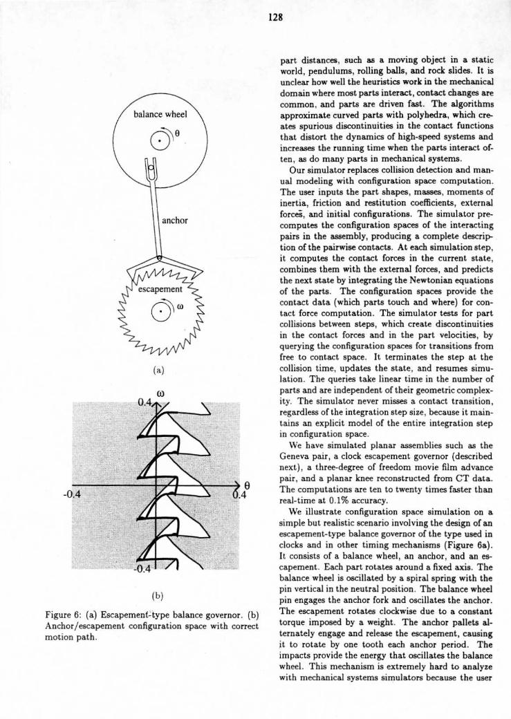
Figure 6 : (a) Escapement-type balance governor . (b)Anchor/escapement configuration space with correctmotion path .
part distances, such as a moving object in a staticworld, pendulums, rolling balls, and rock slides . It isunclear how well the heuristics work in the mechanicaldomain where most parts interact, contact changes arecommon, and parts are driven fast . The algorithmsapproximate curved parts with polyhedra, which cre-ates spurious discontinuities in the contact functionsthat distort the dynamics of high-speed systems andincreases the running time when the parts interact of-ten, as do many parts in mechanical systems .Our simulator replaces collision detection and man-
ual modeling with configuration space computation .The user inputs the part shapes, masses, moments ofinertia, friction and restitution coefficients, externalforces, and initial configurations . The simulator pre-computes the configuration spaces of the interactingpairs in the assembly, producing a complete descrip-tion of the pairwise contacts . At each simulation step,it computes the contact forces in the current state,combines them with the external forces, and predictsthe next state by integrating the Newtonian equationsof the parts . The configuration spaces provide thecontact data (which parts touch and where) for con-tact force computation . The simulator tests for partcollisions between steps, which create discontinuitiesin the contact forces and in the part velocities, byquerying the configuration spaces for transitions fromfree to contact space . It terminates the step at thecollision time, updates the state, and resumes simu-lation . The queries take linear time in the number ofparts and are independent of their geometric complex-ity . The simulator never misses a contact transition,regardless of the integration step size, because it main-tains an explicit model of the entire integration stepin configuration space .We have simulated planar assemblies such as the
Geneva pair, a clock escapement governor (describednext), a three-degree of freedom movie film advancepair, and a planar knee reconstructed from CT data .The computations are ten to twenty times faster thanreal-time at 0.1% accuracy .We illustrate configuration space simulation on a
simple but realistic scenario involving the design of anescapement-type balance governor of the type used inclocks and in other timing mechanisms (Figure 6a) .It consists of a balance wheel, an anchor, and an es-capement . Each part rotates around a fixed axis . Thebalance wheel is oscillated by a spiral spring with thepin vertical in the neutral position . The balance wheelpin engages the anchor fork and oscillates the anchor .The escapement rotates clockwise due to a constanttorque imposed by a weight . The anchor pallets al-ternately engage and release the escapement, causingit to rotate by one tooth each anchor period . Theimpacts provide the energy that oscillates the balancewheel . This mechanism is extremely hard to analyzewith mechanical systems simulators because the user
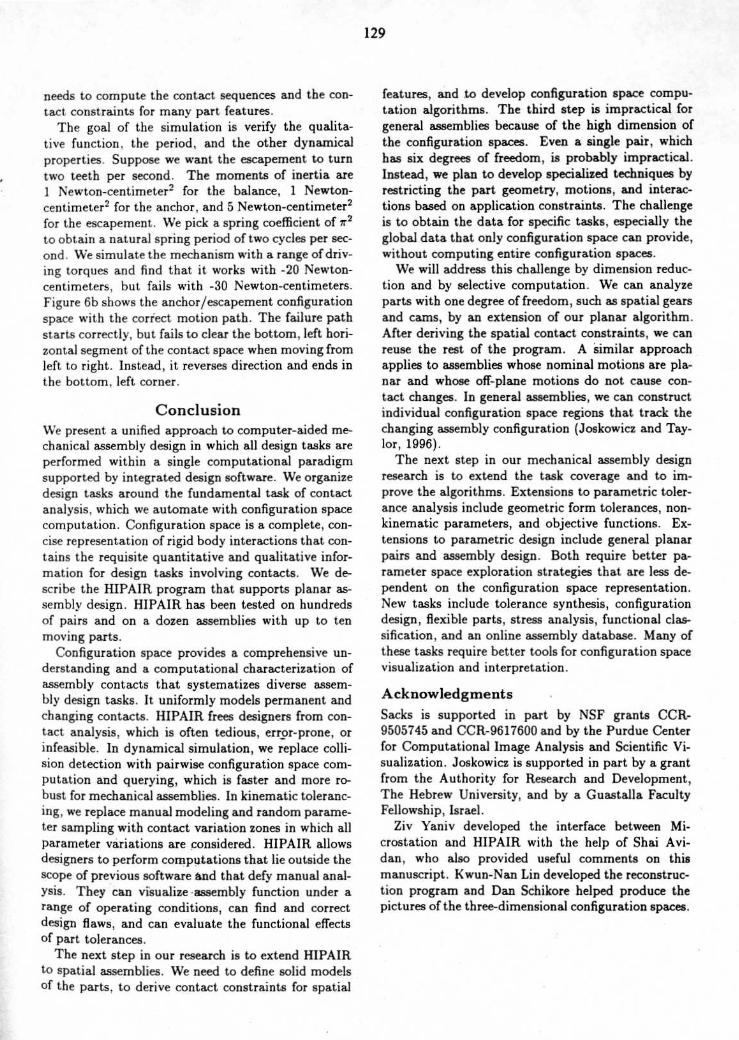
needs to compute the contact sequences and the con-tact constraints for many part features .The goal of the simulation is verify the qualita-
tive function . the period, and the other dynamicalproperties . Suppose we want the escapement to turntwo teeth per second . The moments of inertia areI Newton-centimeter2 for the balance, 1 Newton-centimeter' for the anchor, and 5 Newton-centimeter2for the escapement. We pick a spring coefficient of 7r2
to obtain a natural spring period of two cycles per sec-ond. We simulate the mechanism with a range of driv-ing torques and find that. it works with -20 Newton-centimeters ; but fails with -30 Newton-centimeters .Figure 6b shows the anchor/escapement configurationspace with the correct motion path . The failure pathstarts correctly, but fails to clear the bottom, left hori-zontal segment of the contact space when moving fromleft to right . Instead, it reverses direction and ends inthe bottom, left corner .
ConclusionWe present. a unified approach to computer-aided me-chanical assembly design in which all design tasks areperformed within a single computational paradigmsupported by integrated design software . We organizedesign tasks around the fundamental task of contactanalysis, which we automate with configuration spacecomputation . Configuration space is a complete, con-cise representation of rigid body interactions that con-tains the requisite quantitative and qualitative infor-mation for design tasks involving contacts . We de-scribe the HIPAIR program that supports planar as-sembly design . HIPAIR has been tested on hundredsof pairs and on a dozen assemblies with up to tenmoving parts.
Configuration space provides a comprehensive un-derstanding and a computational characterization ofassembly contacts that systematizes diverse assem-bly design tasks . It uniformly models permanent andchanging contacts . HIPAIR frees designers from con-tact analysis, which is often tedious, error-prone, orinfeasible . In dynamical simulation, we replace colli-sion detection with pairwise configuration space com-putation and querying, which is faster and more ro-bust for mechanical assemblies . In kinematic toleranc-ing, we replace manual modeling and random parame-ter sampling with contact variation zones in which allparameter variations are considered . HIPAIR allowsdesigners to perform computations that lie outside thescope of previous software and that defy manual anal-ysis . They can visualize assembly function under arange of operating conditions, can find and correctdesign flaws, and can evaluate the functional effectsof part tolerances .The next step in our research is to extend HIPAIR
to spatial assemblies . We need to define solid modelsof the parts, to derive contact constraints for spatial
129
features, and to develop configuration space compu-tation algorithms . The third step is impractical forgeneral assemblies because of the high dimension ofthe configuration spaces . Even a single pair, whichhas six degrees of freedom, is probably impractical .Instead, we plan to develop specialized techniques byrestricting the part geometry, motions, and interac-tions based on application constraints. The challengeis to obtain the data for specific tasks, especially theglobal data that only configuration space can provide,without computing entire configuration spaces .We will address this challenge by dimension reduc-
tion and by selective computation . We can analyzeparts with one degree of freedom, such as spatial gearsand cams, by an extension of our planar algorithm .After deriving the spatial contact constraints, we canreuse the rest of the program. A similar approachapplies to assemblies whose nominal motions are pla-nar and whose off-plane motions do not cause con-tact changes . In general assemblies, we can constructindividual configuration space regions that track thechanging assembly configuration (Joskowicz and Tay-lor, 1996) .The next step in our mechanical assembly design
research is to extend the task coverage and to im-prove the algorithms . Extensions to parametric toler-ance analysis include geometric form tolerances, non-kinematic parameters, and objective functions . Ex-tensions to parametric design include general planarpairs and assembly design . Both require better pa-rameter space exploration strategies that are less de-pendent on the configuration space representation .New tasks include tolerance synthesis, configurationdesign, flexible parts, stress analysis, functional clas-sification, and an online assembly database . Many ofthese tasks require better tools for configuration spacevisualization and interpretation .
AcknowledgmentsSacks is supported in part by NSF grants CCR-9505745 and CCR-9617600 and by the Purdue Centerfor Computational Image Analysis and Scientific Vi-sualization . Joskowicz is supported in part by a grantfrom the Authority for Research and Development,The Hebrew University, and by a Guastalla FacultyFellowship, Israel .
Ziv Yaniv developed the interface between Mi-crostation and HIPAIR with the help of Shai Avi-dan, who also provided useful comments on thismanuscript . Kwun-Nan Lin developed the reconstruc-tion program and Dan Schikore helped produce thepictures of the three-dimensional configuration spaces .
References(Baraff, 1992) Baraff, David 1992 . Dynamic Simula-tion of Non-Penetrating Rigid Bodies . Ph .D. Disser-tation, Cornell University.
(Chase and Parkinson, 1991) Chase,
K .
W.
andParkinson, A . R . 1991 . A survey of research in theapplication of tolerance analysis to the design of me-chanical assemblies . Research in Engineering Design3(1) :23-37 .
(Cremer and Stewart, 1989) Cremer, J . F . and Stew-art, A . J . 1989 . The architecture of newton, ageneral-purpose dynamics simulator . In Proceed-ings of the 1989 IEEE International Conference onRobotics and Automation . 1806-1811 .
(de Mello and Lee, . 1991) Mello,
Luiz S. Homemdeand Lee, Sukhan, editors 1991 . Computer-Aided Me-chanical Assembly Planning. Kluwer Academic Pub-lishers .
(Faltings, 1990) Faltings, Boi 1990 . Qualitative kine-matics in mechanisms . Artificial Intelligence 44(1-2) :89-120 .
(Faltings, 1992) Faltings, Boi 1992 . A symbolic ap-proach to qulaitative kinematics . Artificial Intelli-gence 56(2-3) .
(Forbus et al ., 1991) Forbus, K. ; Nielsen, P. ; andFaltings, B . 1991 . Qualitative spatial reasoning : theclock project . Artificial Intelligence 51(1-3) .
(Gonzales-Palacios and Angeles, 1993) Gonzales-Palacios, Max and Angeles, Jorge 1993 . Cam Synthe-sis . Kluwer Academic Publishers, Dordrecht, Boston,London .
(Haug, 1989) Haug, Edward J . 1989 .
Computer-Aided Kinematics and Dynamics of Mechanical Sys-tems, volume 1 : Basic Methods . Simon and Schuster .
(Joskowicz and Sacks, 1991)Joskowicz, Leo and Sacks, Elisha 1991 . Computa-tional kinematics . Artificial Intelligence 51:381-416 .
(Joskowicz and Taylor, 1996) Joskowicz, L. and Tay-lor, R . H . 1996 . Interference-free insertion of a solidbody into a cavity : An algorithm and a medical ap-plication . International Journal of Robotics Research15(3) :211-229 .
(Joskowicz et al ., 1997) Joskowicz, Leo ; Sacks, El-isha, and Srinivasan, Vijay . 1997 . Kinematic toler-ance analysis . Computer-Aided Design 29(2):147-157 .
(Latombe, 1991) Latombe, Jean-Claude 1991 . RobotMotion Planning. Kluwer Academic Publishers .
(Lin et al ., 1996) Lin, Ming C. ; Manocha, Dinesh ;Cohen, Jon; and Gottschalk, Stefan 1996 . Collision
130
detection : Algorithms and applications . In Proceed-ings of the 2nd Workshop on Algorithmic Founda-tions of Robotics.
(Litvin, 1994) Litvin, Faydor L . 1994 . Gear Geometryand Applied Theory. Prentice Hall, New Jersey .
(Mirtich and Canny, 1995) Mirtich,
Brianand Canny, John 1995. Impulse-based dynamic sim-ulation . In Goldberg, K. ; Halperin, D. ; Latombe,J .C . ; and Wilson, R., editors 1995, The AlgorithmicFoundations of Robotics . A. K . Peters, Boston, MA.
(Sacks and Bajaj, 1997) Sacks,
Elisha and Bajaj,Chandrajit 1997 . Sliced configuration spaces forcurved planar bodies . International Journal ofRobotics Research . to appear .
(Sacks and Joskowicz, 1995) Sacks,
Elisha
andJoskowicz, Leo 1995 . Computational kinematic anal-ysis of higher pairs with multiple contacts . Journalof Mechanical Design 117 :269-277 .
(Sacks and Joskowicz, 1996) Sacks,Elisha and Joskowicz, Leo 1996 . Dynamical simu-lation of planar assemblies with changing contactsusing configuration spaces . Technical Report 96-046,Purdue University .
(Sacks and Joskowicz, 1997a) Sacks,
Elishaand Joskowicz, Leo 1997a . Dynamical simulation ofassemblies of planar, ldof parts with changing con-tacts using configuration spaces . In Proceedings ofthe 1997 IEEE International Conference on Roboticsand Automation . IEEE Computer Society Press .
(Sacks and Joskowicz, 1997b)Sacks, Elisha and Joskowicz, Leo 1997b . Parametrickinematic tolerance analysis of planar mechanisms .Computer-Aided Design 27(1) . to appear .
(Schiehlen, 1990) Schiehlen, W. 1990 . Multibody sys-tems handbook. Springer-Verlag .
(Voelcker, 1993) Voelcker, Herbert 1993 . A currentperspective on tolerancing and metrology. Manufac-turing Review 6(4) .