Embed Size (px)
Citation preview

Qualification Procedures formaking PE 3408 Extra HighMolecular WeightYELLOWSTRIPE@ PolyethyleneHeat Fusion Joints
.
BULLETIN NO.106
.
3
4
..56,7
..8
"
Fusion Qualification Procedures. Butt Fusion Joints. Photographs of Butt Fusion Joints
Correctly made butt fusion joints. ..
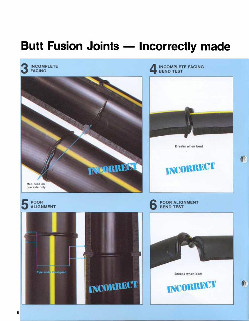
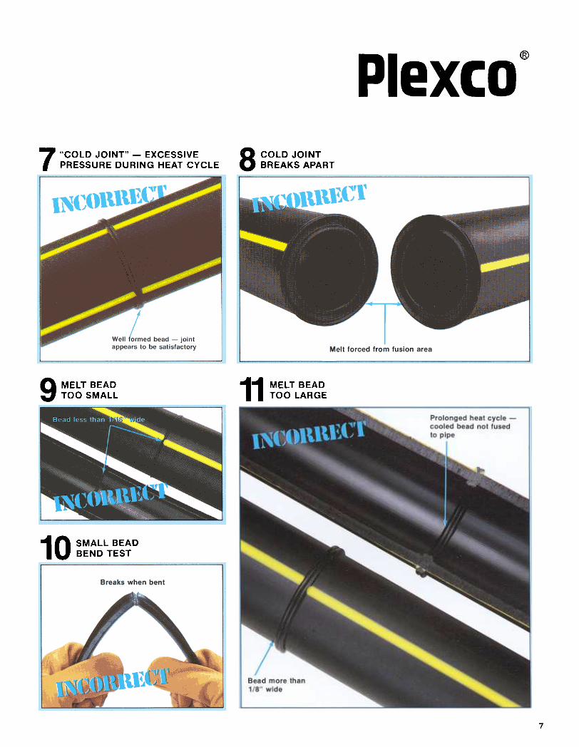
Incorrectly made butt fusion joints. .
Saddle Fusion Joints. Photographs of Saddle Fusion Joints
Correctly made saddle f-usion joints .
Incorrectly made saddle fusion joints
SocketFusionJoints Photographs of Socket Fusion Joints
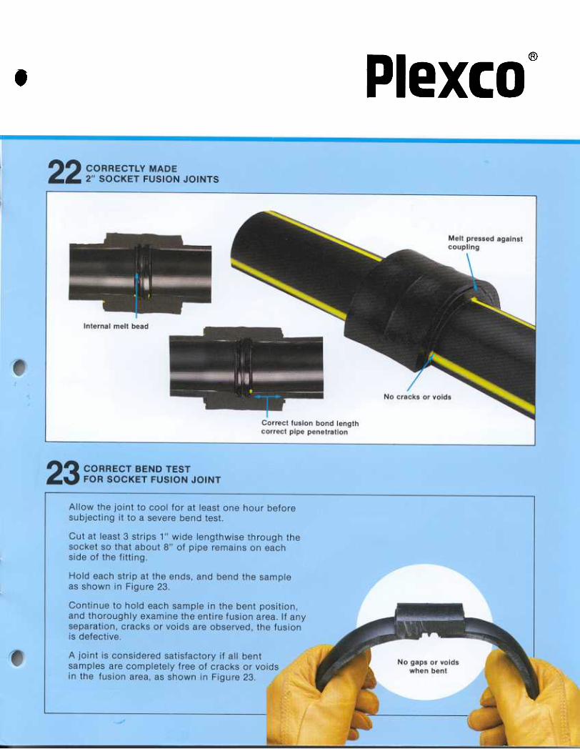
Correctly made socket fusion joints .
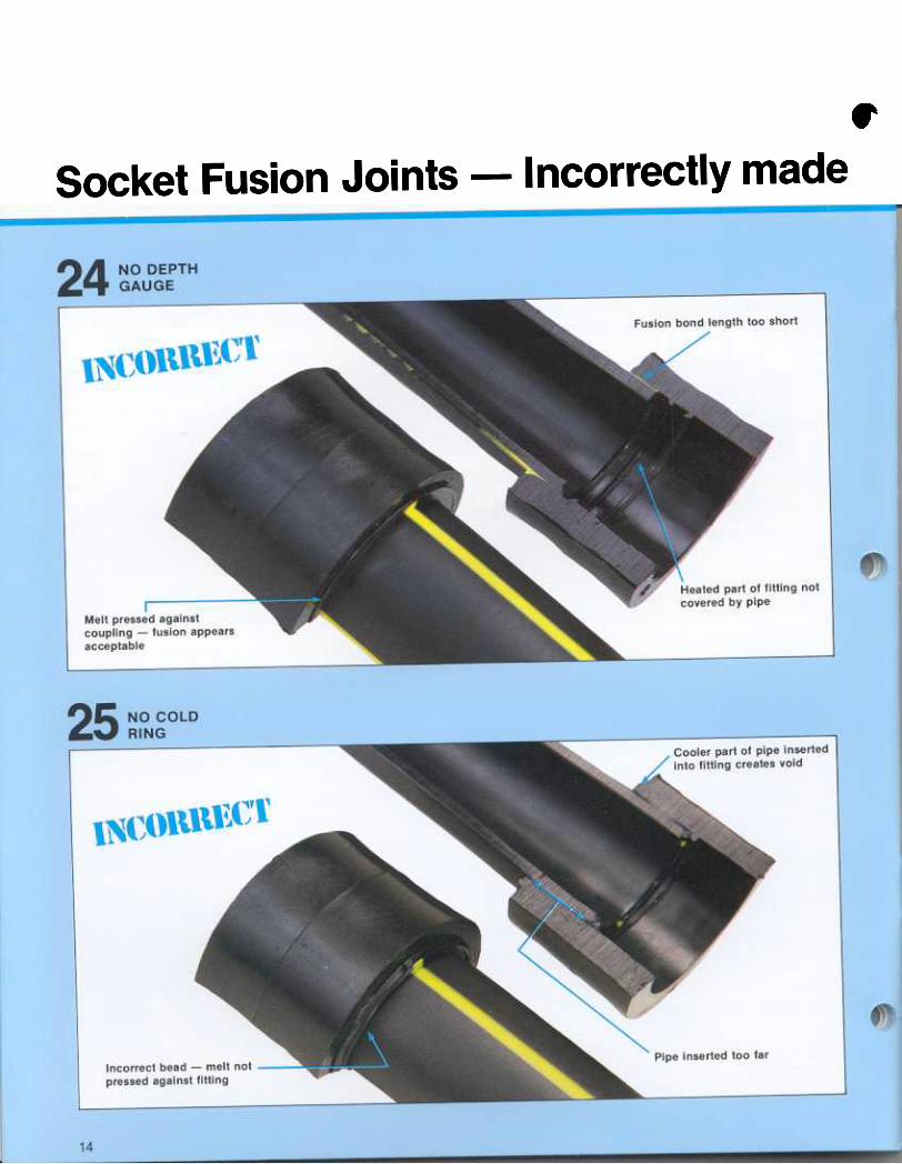
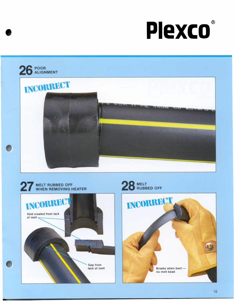
Incorrectly made socket fusion joints
...13
14,15
910, 11
...12
@
This bulletin is intended to serve as an aid for thetraining of personnel as qualified installers ofPLEXCO YELLOWSTRIPE@ polyethylene pipe incompliance with the regulations of the Department ofTransportation, Materials Transportation Bureau,contained in the Code of Federal Regulations Title 49,Part 192. Section 192.285 of these regulations detailsthe procedure to be used to qualify persons to joinplastic pipe. As part of this qualification process, thetrainee must make sample fusion joints in accordancewith the applicable qualified fusion procedure. Theresultant fused joints must have the same visualappearance as correctly made fusion joints describedand illustrated in this bulletin. In addition, each jointmust be cut into at least 3 longitudinal strips, each ofwhich is visually examined and found not to containvoids or discontinuities on the cut surfaces of the jointarea; and deformed by bending, torque, or impactsuch that if failure occurs it does not occur in the jointarea. Refer to Bulletin 101 Fusion Procedures forcomplete fusion procedures.
The pictures in this bulletin are of correctly andincorrectly made butt, saddle and socket fusion joints.They are presented to assist the user in evaluatingheat fusion joints.
PLEXCO YELLOWSTRIPE@ polyethylene pipe andfittings should be joined only by the heat fusionmethod. DO NOT attempt to join by threading or withsolvent cements. If you use compression fittings,instructions for their use should be obtained from thefittings manufacturer.
A fusion joint is made in four simple steps"
1 .Be sure that the surfaces of the fusion tools, pipeand fittings are free of contaminants prior to use.Inspect polyethylene pipe for cuts, gouges, and deepscratches, and remove these pipe sections beforefusing the pipe.
Before you begin fusing, here are some points toremember.
1. All heater surfaces have q thin layer of non-stickcoating that is easily scratched or scraped off. Thiscoating prevents melted PE from adhering firmly tothe heater surfaces but occasionally it, too, must becleaned.
Metal tools should NEVER be used to clean theheater surfaces because they scratch and removethe coating.
Wood implements and clean, dry, lint-free rags arerecommended for cleaning. All-cotton rags arerecommended because rags containing a substantialamount of synthetic fibers may melt and char againstthe heater surface.
If the non-stick coating becomes worn or scratched,the heating unit should be recoated.
Melted PE may adhere to the heating iron and ismore difficult to remove at places where the coatinghas been scraped off.
In addition, since the coating acts as an insulator,heat transfer in these uncoated areas is greater andlocal overheating can occur.
2. Just before using, wipe heaters to remove dirt andforeign material. Clean heaters as soon as possibleafter using with wood implements, and clean rags toremove melted or charred plastic.
3. Check the heater temperature with crayonindicators or surface pyrometer at least once a day tomake sure the thermometer or other temperaturemeasuring device is reading accurately.
Under heavy use conditions, check temperature twicea day.
4. NEVER lay a heating unit on the soil or grasswhen the heat cycle is completed. Return it to holder,if possible, or at least lay it on a board. Soil willcontaminate the joint and is abrasive to the coating;grass may burn and char the heater surface.
Important: All fusion equipment must be in properworking order. Consult the manufacturer's operatingmanual for maintenance and service procedures.Do not use defective equipment.
2. Heat the surfaces to be joined -both the pipe
and fittings -simultaneously at a prescribed
temperature for a specified time.
3. Remove the heater -bring melted surfaces
together.
4. Hold until solidified.
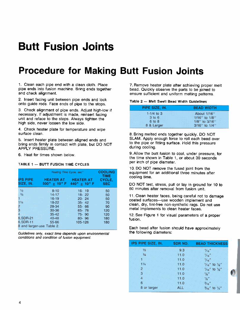
7. Remove heater plate after achieving proper meltbead. Quickly observe the parts to be joined toensure sufficient and uniform melting patterns.
Table 2 -Melt Swell Bead Width Guidelines
1. Clean each pipe end with a clean cloth. Placepipe ends into fusion machine. Bring ends togetherand check alignment.
2. Insert facing unit between pipe ends and lockonto guide rods. Face ends of pipe to the stops.
3. Check alignment of pipe ends. Adjust high-Iow ifnecessary. If adjustment is made, reinsert facingunit and reface to the stops. Always tighten thehigh side, never loosen the low side.
4. Check heater plate for temperature and wipesurface clean.
5. Insert heater plate between aligned ends andbring ends firmly in contact with plate, but DO NOTAPPL y PRESSURE.
6. Heat for times shown below.
TABLE 1 -BUTT FUSION TIME CYCLES
8. Bring melted ends together quickly. DO NOTSLAM. Apply enough force to roll each bead overto the pipe or fitting surface. Hold this pressure
during cooling.
9. Allow the butt fusion to cool, under pressure, forthe time shown in Table 1, or about 30 secondsper inch of pipe diameter .
10. DO NOT remove the fused joint from theequipment for an additional three minutes aftercooling time.
DO NOT test, stress, pull or lay in ground for 10 to60 minutes after.removal from fusion unit.
11. Clean heater f~ces, being careful not to damagecoated surfaces-use wooden implement andclean, dry, lint-free non-synthetic rags. Do not usemetal implements to clean heater faces.
12. See Figure 1 for visual parameters of a properfusion .
Each bead after fusion should have approximatelythe following diameters:Guidelines only, exact time depends upon environmental
conditions and condition of fusion equipment.
4

6
@
8 COLD JOINT
BREAKS APART
7 "COLD JOINT" -EXCESSIVEPRESSURE DURING HEAT CYCLE
11 MELT BEAD
TOO LARGE
9 MELT BEAD
TOO SMALL
1 O SMALL BEAD
BEND TEST
7
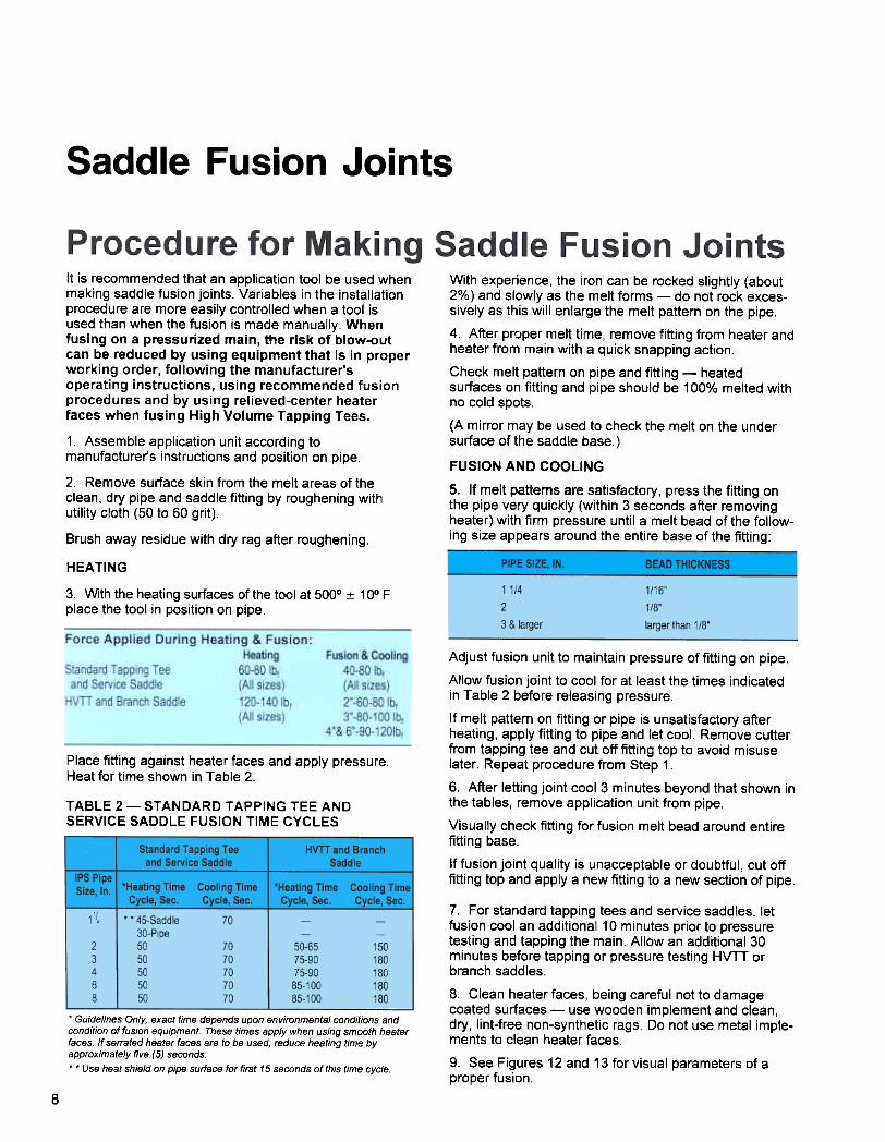
HEATING
3. With the heating surfaces of the tool at 5000 :t 10° F
place the tool in position on pipe.
Place fitting against heater faces and apply pressure.Heat for time shown in Table 2.
TABLE 2- STANDARD TAPPING TEE ANDSERVICE SADDLE FUSION TIME CYCLES
Adjust fusion unit to maintain pressure of fitting on pipe.
Allow fusion joint to cool for at least the times indicatedin Table 2 before releasing pressure.
If melt pattern on fitting or pipe is unsatisfactory afterheating, apply fitting to pipe and let cool. Remove cutterfrom tapping tee and cut off fitting top to avoid misuselater. Repeat procedure from Step 1.
6. After letting joint cool 3 minutes beyond that shown inthe tables, remove application unit from pipe.
Visually check fitting for fusion melt bead around entirefitting base.
If fusion joint quality is unacceptable or doubtful, cut offfitting top and apply a new fitting to a new section of pipe.
7. For standard tapping tees and service saddles, letfusion cool an additional 10 minutes prior to pressuretesting and tapping the main. Allow an additional 30minutes before tapping or pressure testing HVTT orbranch saddles.
8. Clean heater faces, being careful not to damagecoated surfaces -use wooden implement and clean,dry, lint-free non-synthetic rags. Do not use metal imple-ments to clean heater faces.
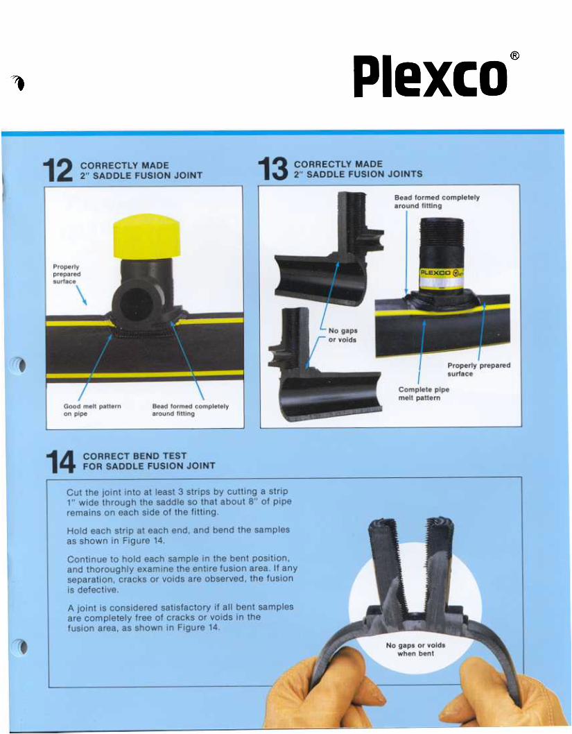
9. See Figures 12 and 13 for visual parameters of aproper fusion.
.Guidelines Only, exact time depends upon environmental conditions andcondition of fusion equipment These times apply when using smooth heaterfaces If serrated heater faces are to be used, reduce heating time byapproximately five (5) seconds
..Use heat shield on pipe surface for first 15 seconds of this time cycle.
8
Force Applied During Heating & Fusion:
HeatingStandard Tapping Tee 60-80 Ibfand Service Saddle (All sizes)
HVTT and Branch Saddle 120-140 Ibf
(All sizes)
Fusion & Cooling40-80 Ibf
(All sizes)2"-60-80 Ibf3'-80-100 Ibf
4'& 6'-90-120Ibf
It is recommended that an application tool be used whenmaking saddle fusion joints. Variables in the installationprocedure are more easily controlled when a tool isused than when the fusion is made manually. Whenfusing on a pressurized main, the risk of blow-outcan be reduced by using equipment that is in properworking order, following the manufacturer'soperating instructions, using recommended fusionprocedures and by using relieved-center heaterfaces when fusing High Volume Tapping Tees.
1. Assemble application unit according tomanufacturer's instructions and position on pipe.
2. Remove surface skin from the melt areas of theclean, dry pipe and saddle fitting by roughening withutility cloth (50 to 60 grit).
Brush away residue with dry rag after roughening.
With experience, the iron can be rocked slightly (about2% ) and slowly as the melt forms -do not rock exces-sively as this will enlarge the melt pattern on the pipe.
4. After proper melt time, remove fitting from heater andheater from main with a quick snapping action.
Check melt pattern on pipe and fitting -heatedsurfaces on fitting and pipe should be 100% melted withno cold spots.
(A mirror may be used to check the melt on the undersurface of the saddle base.)
FUSION AND COOLING
5. If melt patterns are satisfactory , press the fitting onthe pipe very quickly (within 3 seconds after removingheater) with firm pressure until a melt bead of the follow-ing size appears around the entire base of the fitting:
@
,
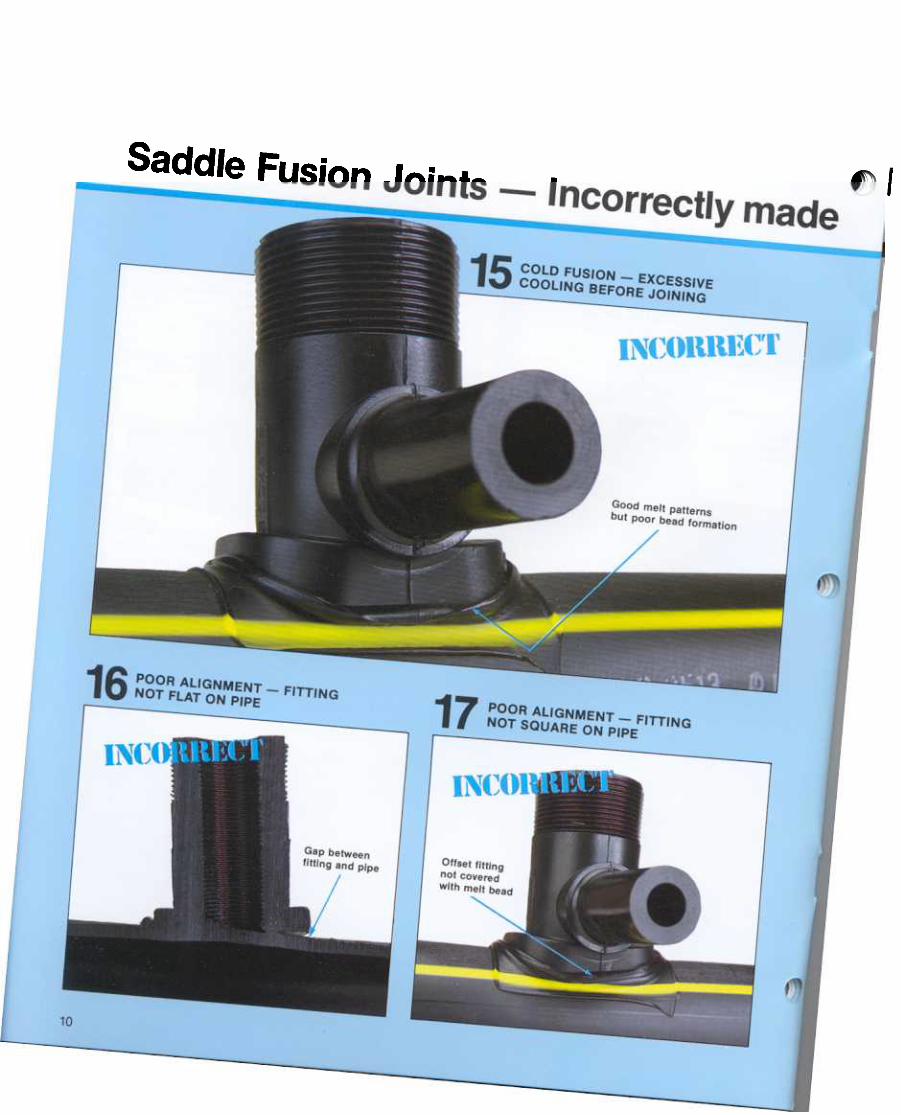
Saddle Fusion Joints -Incorrectly made
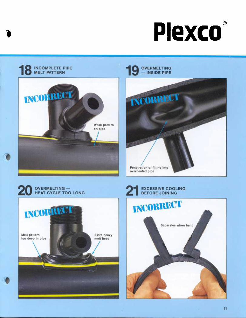
@
1
8. Snap the heating tool and fitting from the meltedpipe by holding upper part of tool handle with onehand and rapping sharply on the handle with the freehand.
Immediately remove fitting from heating tool.
9. Inspect the heated parts quickly to make sure allsurfaces have been melted.
If melt is not complete, cut off melted pipe end, use anew fitting, and repeat fusion steps 1 through 8.
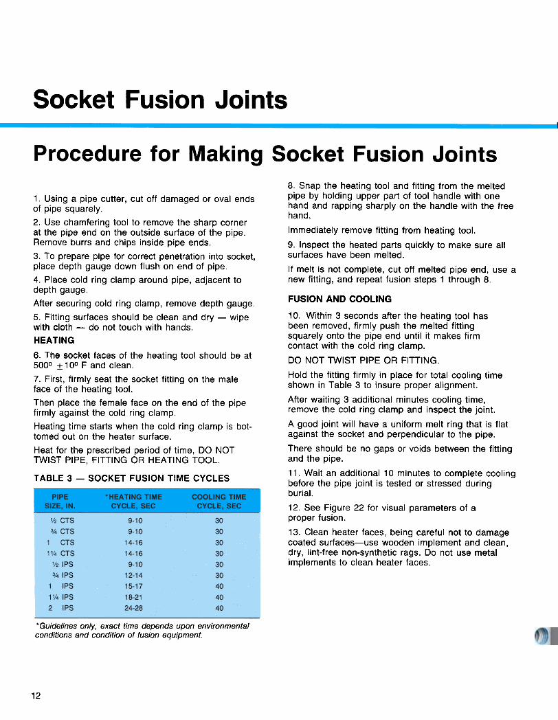
1. Using a pipe cutter, cut off damaged or oval endsof pipe squarely.
2. Use chamfering tool to remove the sharp cornerat the pipe end on the outside surface of the pipe.Remove burrs and chips inside pipe ends.
3. To prepare pipe for correct penetration into socket,place depth gauge down flush on end of pipe.
4. Place cold ring clamp around pipe, adjacent todepth gauge.After securing cold ring clamp, remove depth gauge.
5. Fitting surfaces should be clean and dry -wipewith cloth -do not touch with hands.
HEATING
6. The socket faces of the heating tool should be at5000 :t 10° F and clean.
7. First, firmly seat the socket fitting on the maleface of the heating tool.
Then place the female face on the end of the pipefirmly against the cold ring clamp.
Heating time starts when the cold ring clamp is bot-tomed out on the heater surface.
Heat for the prescribed period of time, DO NOTTWIST PIPE, FITTING OR HEATING TOOL.
T ABLE 3 -SOCKET FUSION TIME CYCLES
FUSION AND COOLING
10. Within 3 seconds after the heating tool hasbeen removed, firmly push the melted fittingsquarely onto the pipe end until it makes firmcontact with the cold ring clamp.
DO NOT TWIST PIPE OR FITTING.
Hold the fitting firmly in place for total cooling timeshown in Table 3 to insure proper alignment.
After waiting 3 additional minutes cooling time,remove the cold ring clamp and inspect the joint.
A good joint will have a uniform melt ring that is flatagainst the socket and perpendicular to the pipe.
There should be no gaps or voids between the fittingand the pipe.
11. Wait an additional 10 minutes to complete coolingbefore the pipe joint is tested or stressed duringburial.
12. See Figure 22 for visual parameters of aproper fusion.
13. Clean heater faces, being careful not to damagecoated surfaces-use wooden implement and clean,dry, lint-free non-synthetic rags. Do not use metalimplements to clean heater faces.
*Guidelines only, exact time depends upon environmentalconditions and condition of fusion equipment.
12
@
.
..
@


![[Order or Directive dated 3/19/13] - Carl PersonMs. xxxx's understanding, CPLR 3408 specifically states that one of the purposes of 3408 is to Page 6 (last page of 3/19/13 Directive):](https://img.pdfslide.us/doc/110x75/5e93b7ff4eaf3a10ac43ad55/order-or-directive-dated-31913-carl-ms-xxxxs-understanding-cplr-3408-specifically.jpg)