Embed Size (px)
Citation preview
Qualification of Phased Array Ultrasonic Testing (PAUT)
Welding control of tubular low thickness assemblies
KINT SYMPOSIUM30/31 October 2019 -Shell Amsterdam
Nizar GHARS, ultrasonic methods specialist, IS Experts
SUMMARY
• INTRODUCTION
• STRATEGY FOR TECHNICAL DEVIATION
Consideration of regulatory VT/RT criteria in terms of nature and size
Definition of an operating mode
Validation of the detection capability on test blocks and with Degital
Calculation (with CIVA)
Blind tests on qualification samples
• RESULT and FEEDBACK
• CONCLUSION
2
Introduction
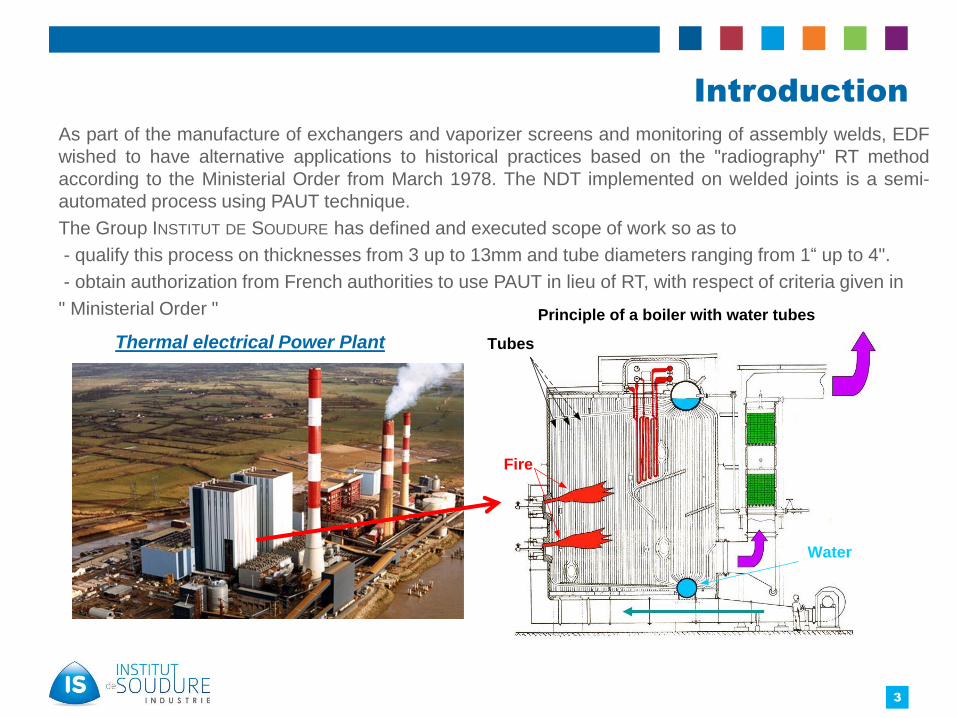
As part of the manufacture of exchangers and vaporizer screens and monitoring of assembly welds, EDF
wished to have alternative applications to historical practices based on the "radiography" RT method
according to the Ministerial Order from March 1978. The NDT implemented on welded joints is a semi-
automated process using PAUT technique.
The Group INSTITUT DE SOUDURE has defined and executed scope of work so as to
- qualify this process on thicknesses from 3 up to 13mm and tube diameters ranging from 1“ up to 4".
- obtain authorization from French authorities to use PAUT in lieu of RT, with respect of criteria given in
" Ministerial Order "
Thermal electrical Power Plant
3
Fire
Tubes
Water
Principle of a boiler with water tubes

Introduction
What
UT examination of weld tubes in alternative of radiographic testing.
When
Tube with small diameter and/or small thickness,
Strong difficulties for the NDT implementation,
Confined space.
Challenge:
Allow the inspection with other workers,
Decrease the examination duration,
With a cost ≤ radiography (weld unit price),
Without increasing the repair rate.
4

5
STRATEGY FOR TECHNICAL DEVIATIONStrategy
Consideration of regulatory VT/RT criteria in terms of nature and size
Involvement of the authorities from the start
Definition of an operating mode
Validation of the detection capability on test blocks and with numerical calculation (with CIVA)
Blind tests on qualification samples
Expected justifications : The impact analyzises of the parameters in their area of variation use:
- theoretical approaches (engineering reasoning) and / or,
- experimental tests and / or,
- simulations using adapted modeling software.(CIVA , ESBeamtools..)
NDT PerformanceImpact analysis
Technique assembly Defect ScannerCoverage JT1.1 JT1.2 JT1.3 JT1.4Evaluation level JT2.1 JT2.2 JT2.3 JT2.3lengthmeasurement
JT3.1 JT3.2 JT3.3 JT3.3
localization JT4.1 JT4.2 - -Classification JT5.1 JT5.2 JT5.3 -sensitivity* JT6.1 JT6.2 JT6.3 -* size of the smallest detectable defectAnalysis to decline for each technique, each default type, semi-
automated and manual
5

STRATEGY FOR TECHNICAL DEVIATION Assembly configuration
The examination area includes weld metal and the heat affected zone.
Tube assemblies of exchangers and screen vaporizers:
- Material:
oUnalloyed carbon steels: TU48
oLow alloy steels : 15CD205 / 13CrMo45 / 10CrMo910
oHighly alloyed steels: X10CrMo NbV9.01 (P91)
- External diameter of the tubes: from 1’’ to 4’’
- Thickness of the tubes: from 3.2 to 13mm
- Inter-tube space: 12mm
- Butt welds with V bevel: Angle α=30° and 37°
6

STRATEGY FOR TECHNICAL DEVIATION
RT criteria in terms of nature and size:
Examination of the weld covers the detection, localization and classification of
discontinuities according to the criteria of the Ministerial Order from March 1978.
The rating level values in PAUT are subject to a technical justification. They are defined
to ensure the detection of all "non-conform" defects. Their choice takes into account the
sufficient sensitivity margins for the impacts of significant influential parameters on the
examination area.
7
Type of defect Criteria of non-conformity
NON VOLUMETRIC DEFECT Always unacceptable
VOLUMETRIC DEFECT TYPE POROSITY Any porosity whose diameter is greater than thesmaller of the two values 6 mm or t/3.
VOLUMETRIC DEFECTS TYPE ALIGNED POROSITY Any alignment of porosities whose cumulated lengthexceeds t over a length equal to the smaller of thetwo values 12t or 150mm.
VOLUMETRIC DEFECTS TYPE SLAG Any inclusion whose length is greater than 20 mm, orthe greater of the two values: 6 mm or t/ 3.
VOLUMETRIC DEFECTS TYPE CLUSTERS OF SLAGS Any group of inclusions whose cumulated length isgreater than 2t over a welded length equal to 12t.
EXCESSIVE PENETRATION OF THE ROOT Height> 3 mm
LACK OF ROOT PENETRATION Height greater than the smallest of the two values: 2mm or 1/10 t
Nota: t = thickness
STRATEGY FOR TECHNICAL DEVIATION
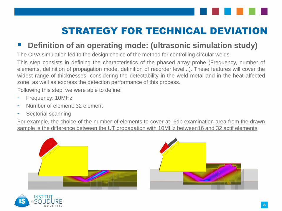
Definition of an operating mode: (ultrasonic simulation study)The CIVA simulation led to the design choice of the method for controlling circular welds.
This step consists in defining the characteristics of the phased array probe (Frequency, number of
elements, definition of propagation mode, definition of recorder level...). These features will cover the
widest range of thicknesses, considering the detectability in the weld metal and in the heat affected
zone, as well as express the detection performance of this process.
Following this step, we were able to define:
- Frequency: 10MHz
- Number of element: 32 element
- Sectorial scanning
For example, the choice of the number of elements to cover at -6db examination area from the drawn
sample is the difference between the UT propagation with 10MHz between16 and 32 actif elements
8

STRATEGY FOR TECHNICAL DEVIATION
Definition of an operating mode
NDT technique:
– Phased Array UT (PAUT)
Sectoral scanning Ability to deflect
the acoustic beam at different angles.
Equipment:
– Encoding, guiding scanner,
– Miniaturized PA probes,
– Acquisition unit on battery,
– Possible to configure scanner for
one-side inspection.
9

STRATEGY FOR TECHNICAL DEVIATION
Validation of the detection capability on test blocks and with digital calculation (with CIVA)
To do this, it was necessary to define the reference and validation blocks of the method. This phase aims to validate the CIVA simulation study by experimental test:
- 3 reference blocks with diameters 1, 2’’ and 3.5’’ to cover all diameters and thicknesses to be examined
- 20 validation blocks with welding defects (Porosity, Slag, lack of fusion and crack):
o 10 with a diameter of 2.5’’ and thickness 8 mm
o 10 with a diameter of 1.5’’ and thickness 4mm
- These blocks are made of the same material and welding process as the site.
This reference block is used to:
- perform DAC/TCG
- check time delays (related to the shoe wear)
and index point
10

STRATEGY FOR TECHNICAL DEVIATION
For example: the configuration of the calibration with reference blocks does not take intoaccount the impact of the rebound on the response of hole reflectors. The followingcurves summarize the results of the rebound impact values on the TCG:
11
Calibration setup
Control configuration
Angles
Sound path (mm)
TCG curve of different focal laws on a tube 1 '‘, thickness 3 mm
With and Without rebound
Re
spo
nse
(dB
)
½ Skip
Skip
Skip and
1/2
2dB

STRATEGY OF TECHNICAL DEVIATION
2nd example of calculating of the defect response
12
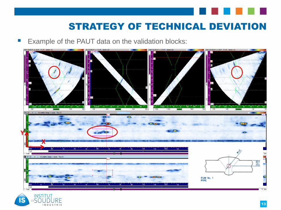
STRATEGY OF TECHNICAL DEVIATION
Example of the PAUT data on the validation blocks:
13
X
Y

STRATEGY OF TECHNICAL DEVIATION
14
Performance of PAUT:
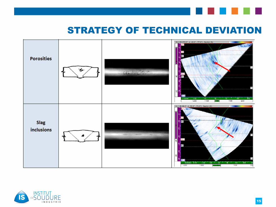
STRATEGY OF TECHNICAL DEVIATION
15

STRATEGY OF TECHNICAL DEVIATION
Blind tests on qualification samples- blocks with welding defects :
o 8 Circular welds with a diameter 1.5’’ and thickness 5 mm
o 8 Circular welds with a diameter 2.5’’, thickness 4 mm
16

STRATEGY OF TECHNICAL DEVIATION
Blind tests on qualification samples (example of defect and
report)
17

Results and Feedback
Feedback: The first feedback on the site
- Duration of the shutdown: 3 weeks
- Number of technicians : 2 up to 3
- Difficult access conditions and proximity of welders
- Number of controlled welds: 600 (between 40 and 60 welds per day)
- Types of defects: essentially lack of fusion and lack of penetration
Evolution of the daily repair rate
18
Day
% o
f re
pai
r
This defect is not detectable with RT

Results and Feedback
Results
- Acceptance and Qualification the PAUT Welding control of tubular low
thickness assemblies by French authorities
- Study duration ~ 4 months
- Operating mode and acceptance criteria in compliance with code
- Qualified personnel with strong professional background
- > 1000 welds examined in accordance with requested regulatory NDT
inspection
19

Results and Feedback
Advantages and Benefits versus RT:
- Repaired rate equivalent to RT one
- PAUT inspection rate better than 4x of RT (rate of 50/70 welds per day)
- Increase of the inspection daily rate with specialist team, and results delivered in real
time (C/NC)
- Evaluation of the defect size according to 3 axis
- Improvement of the weld quality and adjustment of the welding process (Real-time
analysis and on-site communication with welders)
- POD (Probability Of Detection) better than RT examination (planar defects!)
- Traceability on digital support
- Production : No interruption of production due to radiation
Safety : No ionizing radiation
20
Conclusions
• The implementation of Phased Array Technology for the control
of welds during fabrication/ maintenance allows :
- To obtain a significant reduction in production times and
an improvement in the quality of the welds with respect
to harmful defects.
• The benefits are fully recognized by owners (operators) who
require more and more to replace the radiography by this type
of control.
• The group INSTITUT DE SOUDURE is much involved in the drafting
of EN Standard ISO 20601 through the present development,
use of phased array technology for thin-walled steel
components.
21

Thank you for your attention!
Nizar GHARS – specialist in ultrasonic methods
22


![Non€¦ · and common NDT techniques. Keywords: Non-intrusive inspection [NII], Phased array ultrasonic testing [PAUT], Fitness – for – service [FFS], Computed radiography [CR],](https://img.pdfslide.us/doc/110x75/6039bfe787aa56292402f29d/non-and-common-ndt-techniques-keywords-non-intrusive-inspection-nii-phased.jpg)