Embed Size (px)
Citation preview

Qualification of Flexible Fiber-Reinforced
Pipe for 10,000-Foot Water Depths
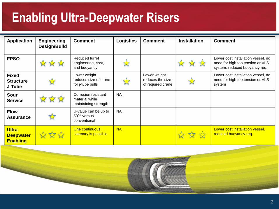
Application Engineering
Design/Build
Comment Logistics Comment Installation Comment
FPSO Reduced turret
engineering, cost,
and buoyancy
Lower cost installation vessel, no
need for high top tension or VLS
system, reduced buoyancy req.
Fixed
Structure
J-Tube
Lower weight
reduces size of crane
for j-tube pulls
Lower weight
reduces the size
of required crane
Lower cost installation vessel, no
need for high top tension or VLS
system
Sour
Service
Corrosion resistant
material while
maintaining strength
NA
Flow
Assurance
U-value can be up to
50% versus
conventional
NA
Ultra
Deepwater
Enabling
One continuous
catenary is possible
NA Lower cost installation vessel,
reduced buoyancy req.
Enabling Ultra-Deepwater Risers
2

Task: a project was set up by Research Partnership to Secure Energy for America
(RPSEA) to develop an ultra-deepwater riser to the following specification.
• 7-inch ID
• 10,000 psi
• 3000m WD
• Sour service
• 120 celsius
This would push flexible riser technology well beyond todays limitations and
enable ultra-deepwater solutions.
Project scope of work involved a three stage process:
• Phase 1 – Engineering study
• Phase 2 – Prototype manufacturing and qualification testing
• Phase 3 – Field deployment supply
Outline
3
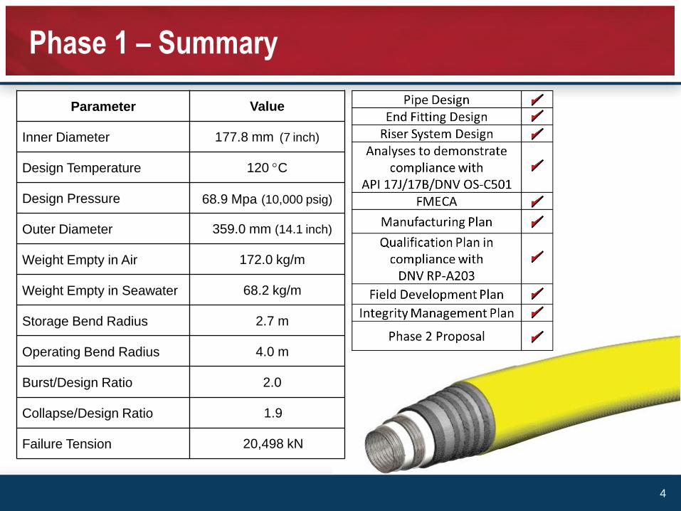
Parameter Value
Inner Diameter 177.8 mm (7 inch)
Design Temperature 120 C
Design Pressure 68.9 Mpa (10,000 psig)
Outer Diameter 359.0 mm (14.1 inch)
Weight Empty in Air 172.0 kg/m
Weight Empty in Seawater 68.2 kg/m
Storage Bend Radius 2.7 m
Operating Bend Radius 4.0 m
Burst/Design Ratio 2.0
Collapse/Design Ratio 1.9
Failure Tension 20,498 kN
Phase 1 – Summary
4
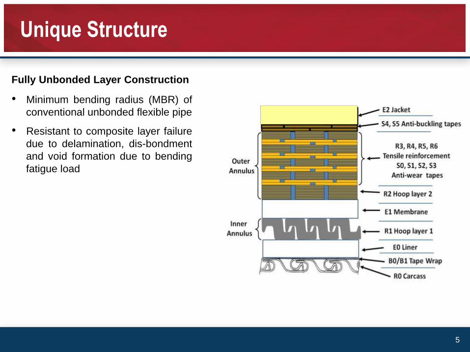
• Minimum bending radius (MBR) of
conventional unbonded flexible pipe
• Resistant to composite layer failure
due to delamination, dis-bondment
and void formation due to bending
fatigue load
Fully Unbonded Layer Construction
Unique Structure
5
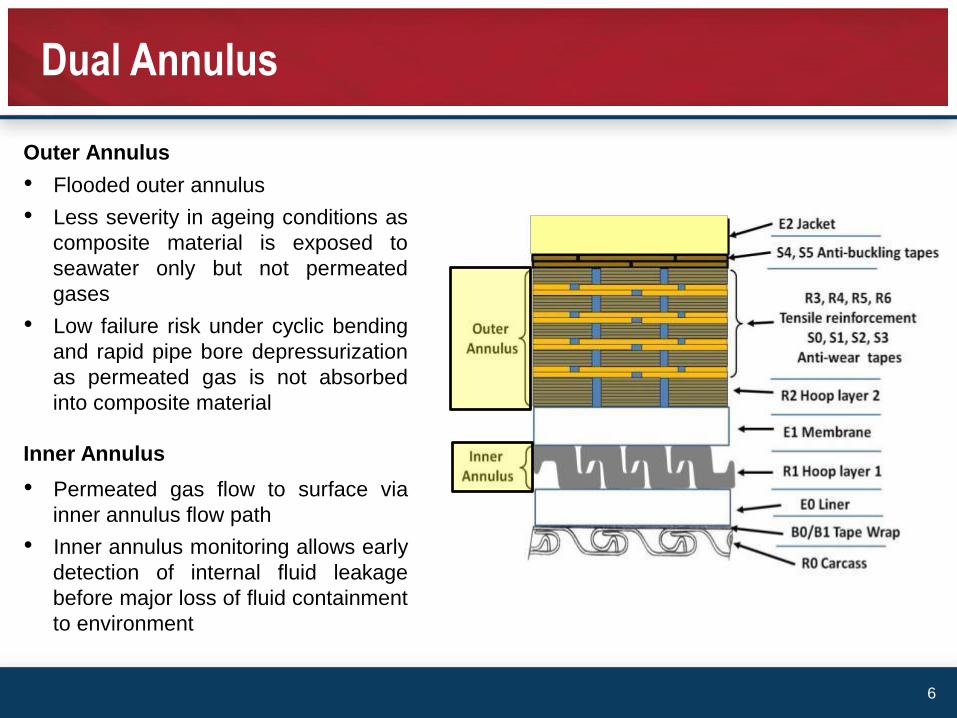
Inner Annulus
Dual Annulus
Outer Annulus
• Flooded outer annulus
• Less severity in ageing conditions as
composite material is exposed to
seawater only but not permeated
gases
• Low failure risk under cyclic bending
and rapid pipe bore depressurization
as permeated gas is not absorbed
into composite material
• Permeated gas flow to surface via
inner annulus flow path
• Inner annulus monitoring allows early
detection of internal fluid leakage
before major loss of fluid containment
to environment
6
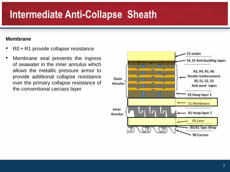
Intermediate Anti-Collapse Sheath
Membrane
• R0 + R1 provide collapse resistance
• Membrane seal prevents the ingress
of seawater in the inner annulus which
allows the metallic pressure armor to
provide additional collapse resistance
over the primary collapse resistance of
the conventional carcass layer
7

Hybrid Pressure Armor
Hybrid Pressure Armor
• Proven technology for primary fluid
and pressure containment
• Composite hoop layer as a back
up pressure armor for increased
pressure capacity (patent pending)
8

Composite Tensile Armor
Composite Tensile Armor
• Zero risk of corrosion as composite
material does not corrode in seawater
• Stable helical shape of tensile armors
provide sufficient axial compression
capacity for the pipe
• Low risk of fatigue
9
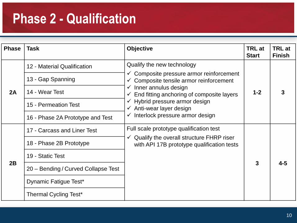
Phase Task Objective TRL at
Start
TRL at
Finish
2A
12 - Material Qualification Qualify the new technology
Composite pressure armor reinforcement
Composite tensile armor reinforcement
Inner annulus design
End fitting anchoring of composite layers
Hybrid pressure armor design
Anti-wear layer design
Interlock pressure armor design
1-2 3
13 - Gap Spanning
14 - Wear Test
15 - Permeation Test
16 - Phase 2A Prototype and Test
2B
17 - Carcass and Liner Test Full scale prototype qualification test
Qualify the overall structure FHRP riser
with API 17B prototype qualification tests
3 4-5
18 - Phase 2B Prototype
19 - Static Test
20 – Bending / Curved Collapse Test
Dynamic Fatigue Test*
Thermal Cycling Test*
Phase 2 - Qualification
10
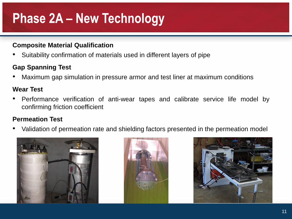
Phase 2A – New Technology
Composite Material Qualification
• Suitability confirmation of materials used in different layers of pipe
Gap Spanning Test
• Maximum gap simulation in pressure armor and test liner at maximum conditions
Wear Test
• Performance verification of anti-wear tapes and calibrate service life model by
confirming friction coefficient
Permeation Test
• Validation of permeation rate and shielding factors presented in the permeation model
11
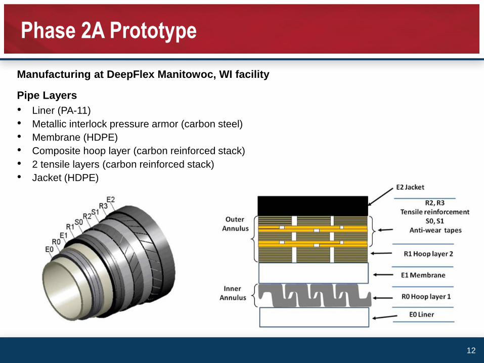
Manufacturing at DeepFlex Manitowoc, WI facility
Pipe Layers
• Liner (PA-11)
• Metallic interlock pressure armor (carbon steel)
• Membrane (HDPE)
• Composite hoop layer (carbon reinforced stack)
• 2 tensile layers (carbon reinforced stack)
• Jacket (HDPE)
Phase 2A Prototype
12
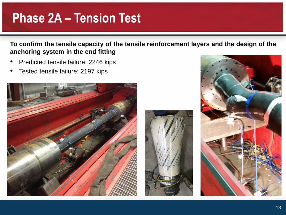
To confirm the tensile capacity of the tensile reinforcement layers and the design of the
anchoring system in the end fitting
• Predicted tensile failure: 2246 kips
• Tested tensile failure: 2197 kips
Phase 2A – Tension Test
13
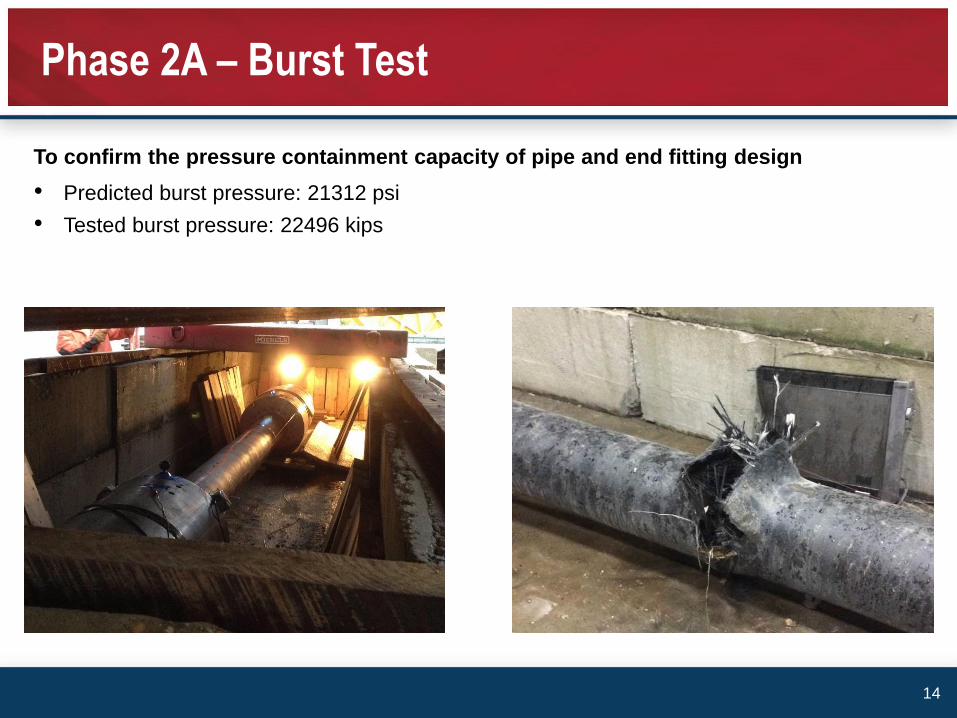
To confirm the pressure containment capacity of pipe and end fitting design
• Predicted burst pressure: 21312 psi
• Tested burst pressure: 22496 kips
Phase 2A – Burst Test
14
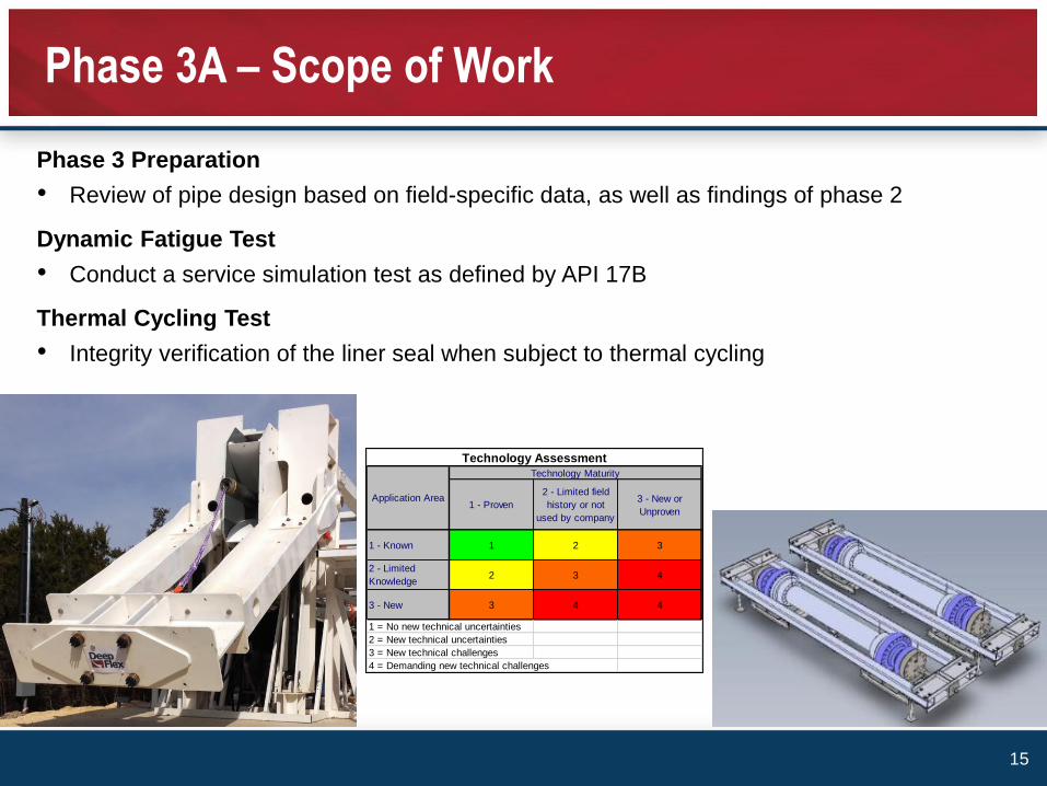
1 - Proven
2 - Limited field
history or not
used by company
3 - New or
Unproven
1 - Known 1 2 3
2 - Limited
Knowledge2 3 4
3 - New 3 4 4
1 = No new technical uncertainties
2 = New technical uncertainties
3 = New technical challenges
4 = Demanding new technical challenges
Application Area
Technology Maturity
Technology Assessment
Phase 3 Preparation
• Review of pipe design based on field-specific data, as well as findings of phase 2
Dynamic Fatigue Test
• Conduct a service simulation test as defined by API 17B
Thermal Cycling Test
• Integrity verification of the liner seal when subject to thermal cycling
Phase 3A – Scope of Work
15
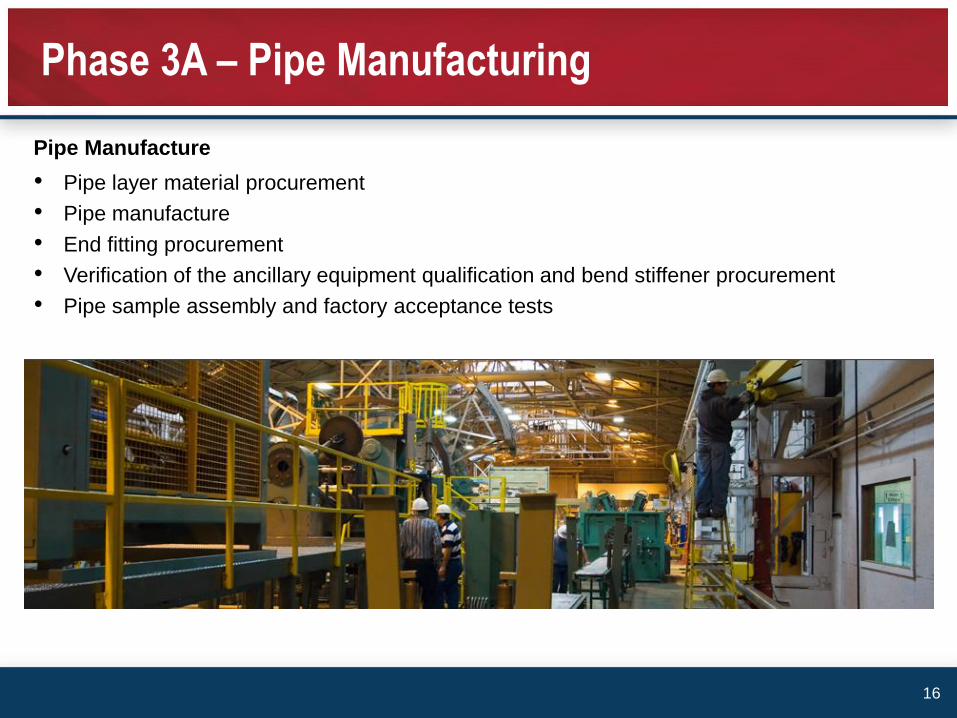
Pipe Manufacture
• Pipe layer material procurement
• Pipe manufacture
• End fitting procurement
• Verification of the ancillary equipment qualification and bend stiffener procurement
• Pipe sample assembly and factory acceptance tests
Phase 3A – Pipe Manufacturing
16
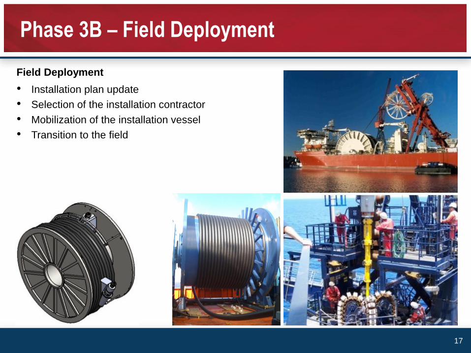
Field Deployment
• Installation plan update
• Selection of the installation contractor
• Mobilization of the installation vessel
• Transition to the field
Phase 3B – Field Deployment
17

Integrity Management
• Integrity management plan update
• Contracting the equipment supplier
• Inspection
• Monitoring
Phase 3B – Integrity Management
18
DeepFlex have developed an ultra-deepwater riser to 7” ID, 10,000psi, 3000m WD, sour
conditions at 120 Celsius
Utilizing composite technology pushes flexible riser technology well beyond todays
limitations to enable ultra-deepwater riser solutions
Project Scope of Work involved a three phase process
• Phase 1 – Engineering Design
o Flexible unbonded design
o Dual annulus
o Hybrid pressure armor
o Composite tensile armor
Reducing flexible pipe mass while retaining
strength reduces top tension enabling ultra-
deepwater risers to be deployed in dynamic
conditions
Summary
19
• Phase 2 – Prototype Manufacturing and Qualification Testing
o Phase 2A 100% complete
o Phase 2B in progress 100% complete by end 2015
• Phase 3 – Field Deployment Supply
o Manufacturing to commence Q2 2016 with installation Q4 2016
Reducing flexible pipe mass while retaining strength reducing top tension and enabling
ultra-deepwater risers to be deployed in dynamic conditions
Summary
20