Embed Size (px)
Citation preview
Quagga Routing Configuration Guide
Version 2.12

Quagga Routing Configuration Guide – Version 2.12 – revision 1 i
Table of Contents
Chapter 1 Preface to the Routing Guide 1
Document Objectives 1
Related Documentation Erreur ! Signet non défini.
Conventions 1
Chapter 2 IPv4 Unicast Routing Configuration 3
Routing Configuration Overview 3
Save and apply configuration 3
Showing the unicast Routing tables (RIBs and router’s FIB) 4
The IPv4 unicast FIB - show ip route 4
The RIBs of the dynamic routing protocols 4
IPv4 static routes 4
Overview 4
Configuring static routes 5
ECMP 6
Chapter 3 RIP 7
Overview 7
RIP features 7
Split-horizon 7
Split-horizon with poisoned reverse path 7
Next-hop option 8
Triggered update 8
Configuring RIP 8
RIP Configuration Steps 8
RIP Configuration Options 9
RIP features examples 18
RIP states 22
RIP Security 24
RIP Authentication 25
Filtering RIP Routes 25
High Availability 26
Chapter 4 OSPFv2 27
Introduction 27
OSPF terminology 27
Table of Contents
ii Quagga Routing Configuration Guide- Version 2.12 – revision 1
OSPF operation 28
OSPF configuration in a single area 28
Enable OSPF 28
Configure OSPF networks (Mandatory) 28
Verifying OSPF configuration 29
OSPF configuration in single area example 30
Configuring OSPF options 32
OSPF router-id 32
OSPF cost 32
OSPF priority 32
OSPF hello interval 32
OSPF transmit-delay 32
OSPF route summarization 33
Configuring OSPF in multiple areas 33
OSPF area type 33
OSPF router type 33
OSPF Link-state type 33
OSPF operation across multiple areas 34
Route summarization 38
OSPF virtual links overview 40
OSPF stub area overview 43
Totally stubby area overview 43
OSPF NSSA overview 43
OSPF options configuration example 44
OSPFv2 Security 48
OSPF authentication configuration 48
OSPF Filtering 49
Using OSPF in NBMA mode 49
Comparison with other solutions 50
High Availability 51
Chapter 5 BGP4 53
Overview 53
Introduction 54
ASN – Autonomous System Number 54
Configuring BGP 55
The three steps required to configure BGP 55
BGP4 configuration options 58
BGP4 states 71
BGP4 features examples 74
Flush BGP4 sessions 77
Route refresh 77
Soft reconfiguration 78
High Availability 79
BGP4 Security 80
Table of Contents
Quagga Routing Configuration Guide- Version 2.12 – revision 1 iii
BGP4 Filtering 80
BGP4 Authentication 90
BGP Graceful Restart Capability 91
BGP Backdoor 92
Chapter 6 IS-IS 93
Introduction 93
IS-IS Terminology 93
IS-IS Operation 94
IS-IS Advantages 94
Configuring IS-IS 95
Enable IS-IS 95
Activate IS-IS 95
Verifying IS-IS configuration 95
IS-IS Configuration Commands 96
IS-IS Configuration Scenarios 99
IS-IS single-area configuration example 99
IS-IS multi-area configuration example 101
Chapter 7 IPv6 Unicast Routing Configuration 103
Routing Context 103
Displaying Routing Configuration 103
Showing the unicast Routing tables (RIBs and router’s FIB) 104
The IPv6 unicast FIB – show ipv6 route 104
The RIBs of the dynamic IPv6 routing protocols 104
IPv4 and IPv6 static routes 105
Overview 105
Configuring static routes 105
Chapter 8 RIPng 109
Configuring RIPng 109
RIPng Configuration Steps: 109
RIPng Configuration Options 112
Chapter 9 OSPFv3 119
OSPFv3 overview 119
Configuring OSPFv3 in a single area 119
Step 1: Create the OSPFv3 context at the dynamic routing context 119
Step 2: At ospf6 context assign your router an OSPF router-id 119
Step 3: Activate OSPF on the desired interfaces 119
Verifying operation 120
Configuration example 121
OSPFv3 options 122
OSPFv3 cost 122
OSPFv3 priority 122
OSPFv3 hello interval 123
OSPFv3 transmit-delay 123
Table of Contents
iv Quagga Routing Configuration Guide- Version 2.12 – revision 1
Default route advertisement 123
Passive interface 123
OSPFv3 Filtering 124
ECMP 124
Configuring OSPFv3 in multiple areas 124
OSPFv3 virtual links overview 124
OSPFv3 stub area overview 125
Totally stubby area overview 125
OSPFv3 NSSA overview 125
Chapter 10 BGP4+ 127
Configuring BGP4+ 127
The differences between BGP4 and BGP4+ 127
The four required steps to configure BGP4+ 127
BGP4+ features examples 131
BGP4+ configuration options 135
BGP4+ states 148
Flush BGP4+ sessions 149
Route refresh 150
Soft reconfiguration 150
BGP4+ Graceful Restart Capability 151
BGP4+ Backdoor 151
Chapter 11 IS-IS in IPv6 networks 152
Introduction 152
Configuring IS-IS 152
Enable IS-IS 152
Activate IS-IS 152
Verifying IS-IS configuration 153
IS-IS Configuration Commands 153
IS-IS Configuration Scenarios 156
IS-IS single-area configuration example 156
IS-IS multi-area configuration example 158
Appendix A List of Acronyms 161
Quagga Routing Configuration Guide – Version 2.12 – revision 1 v
List of Figures Figure 1 – Example illustrating RIP options ................................................................................................................. 16
Figure 2 – RIPv2 split-horizon ...................................................................................................................................... 18
Figure 3 – The next-hop feature .................................................................................................................................... 20
Figure 4 – First OSPFv2 configuration ......................................................................................................................... 30
Figure 5 – OSPFv2 operation across multiple areas ...................................................................................................... 34
Figure 6 – OSPFv2 router configuration in multi-area environment ............................................................................. 34
Figure 7 – OSPFv2 virtual link example ....................................................................................................................... 41
Figure 8 – OSPFv2 options configuration example....................................................................................................... 44
Figure 9 – the EGP (BGP) vs. the IGPs (RIP, RIPng, OSPFv2, OSPFv3, IS-IS) ......................................................... 53
Figure 10 – your First BGP4 configuration ................................................................................................................... 56
Figure 11 – BGP4 aggregation ...................................................................................................................................... 59
Figure 12 – BGP4 confederation ................................................................................................................................... 64
Figure 13 – route reflectors ........................................................................................................................................... 66
Figure 14 – Simplification of the configuration, thanks to peer-group ......................................................................... 68
Figure 15 – Private AS .................................................................................................................................................. 69
Figure 16 – resolution of the next-hop with BGP4 ........................................................................................................ 74
Figure 17 – BGP High Availability with MED ............................................................................................................. 79
Figure 18 – Aggregation with suppressed prefixes, however without the flag summary-only. ................................... 83
Figure 19 - BGP4 AS-path filters .................................................................................................................................. 87
Figure 20 – BGP community no-export ........................................................................................................................ 89
Figure 21 – IPv4 and IPv6 static routing example ...................................................................................................... 106
Figure 22 – Your first RIPng configuration ................................................................................................................ 110
Figure 23 – RIPng options configuration example ...................................................................................................... 116
Figure 24 – basic OSPFv3 configuration .................................................................................................................... 121
Figure 25 – BGP4+ basic configuration ...................................................................................................................... 129
Figure 26 – resolution of the next-hop with BGP4+ ................................................................................................... 131
Figure 27 – BGP4+ aggregation .................................................................................................................................. 136
Figure 28 – BGP+ confederation ................................................................................................................................. 140
Figure 29 – route reflectors ......................................................................................................................................... 143
Figure 30 – Simplification of the configuration, thanks to peer-group ....................................................................... 145
Figure 31 – Private AS ................................................................................................................................................ 146

Quagga Routing Configuration Guide – Version 2.12 – revision 1 1
Chapter 1 Preface to the Routing Guide
This chapter discusses the objectives, organization, related documentation and conventions of
the Routing Configuration Guide.
Document Objectives
This Routing Configuration Guide describes the tasks and commands necessary to configure and
manage your equipment.
Conventions
The following conventions are used to attract the attention of the reader:
Caution Means reader be careful. In this situation, you might do something that could result in
equipment damage or loss of data.
Note Means reader take note. Notes contain helpful suggestions or references to materials not
contained in this manual.
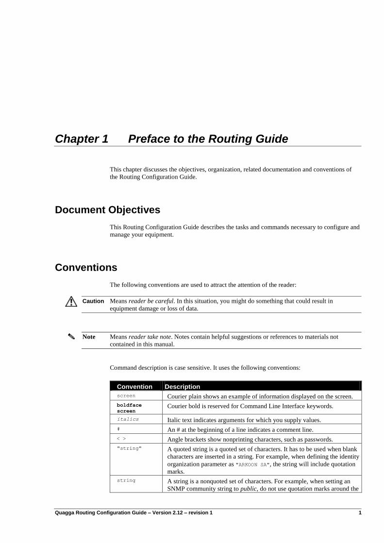
Command description is case sensitive. It uses the following conventions:
Convention Description
screen Courier plain shows an example of information displayed on the screen.
boldface
screen Courier bold is reserved for Command Line Interface keywords.
italics Italic text indicates arguments for which you supply values.
# An # at the beginning of a line indicates a comment line.
< > Angle brackets show nonprinting characters, such as passwords.
"string" A quoted string is a quoted set of characters. It has to be used when blank
characters are inserted in a string. For example, when defining the identity
organization parameter as "ARKOON SA", the string will include quotation
marks.
string A string is a nonquoted set of characters. For example, when setting an
SNMP community string to public, do not use quotation marks around the
Preface to the Routing Guide
2 Quagga Routing Configuration Guide- Version 2.12 – revision 1
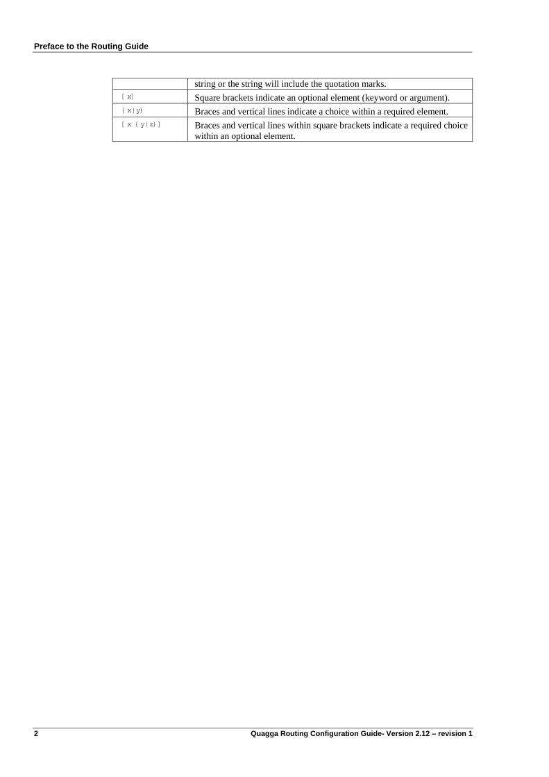
string or the string will include the quotation marks.
[x] Square brackets indicate an optional element (keyword or argument).
{x|y} Braces and vertical lines indicate a choice within a required element.
[x {y|z}] Braces and vertical lines within square brackets indicate a required choice
within an optional element.
Quagga Routing Configuration Guide – Version 2.12 – revision 1 3
Chapter 2 IPv4 Unicast Routing Configuration
This chapter describes how to configure routing functions for IPv4. It requires only some
knowledge of the basic principles of IPv4 features.
“Routing is more the art to advertise how to be reached
rather than the art to learn how to reach.”
Routing Configuration Overview
The routing functions can be configured using static routes or any dynamic routing protocol. The
IPv4 routing protocols that are provided within the Quagga software are:
RIPv1 and RIPv2
OSPFv2
BGP4
Save and apply configuration
After each modification performed when you are directly editing the “running” configuration,
you can exit the dynamic routing context and then apply the new parameters with the following
command:
rt1{running-rtg}addrunning
Conversely, you can apply globally all the modifications at one time. To do this, exit the
different contexts you have reached. Once you exit the configuration which you are editing, the
router will ask you whether you‟d like to save it or not
WARNING : Would you like to save this config (y/n)?[y]
Answer yes by typing „y‟
At this level you can apply your configuration by typing at the global router context
rt1{}apply myconfig
IPv4 Unicast Routing Configuration
4 Quagga Routing Configuration Guide- Version 2.12 – revision 1
Showing the unicast Routing tables (RIBs and router’s FIB)
The FIB is the Forwarding Information Base. It contains the aggregated information from all the
Routing Information Bases (RIBs) that have been discovered by the dynamic routing protocols
or that have been set statically. There is one RIB for each routing protocol: a RIP RIB, an
OSPFv2 RIB, and an IPv4 BGP4 RIB.
The IPv4 unicast FIB can be monitored with the show ip route command.
The IPv4 unicast FIB - show ip route
The show ip route command dumps the IPv4 unicast routes (the IPv4 Forwarding
Information Base – IPv4 FIB) currently used by the routers. The routes can be statically
configured or automatically learnt by a routing protocol.
rt1{show-route}show ip route
Codes: K - kernel route, C - connected, S - static, R - RIP, O - OSPF,
B - BGP, D - DEP, > - selected route, * - FIB route
C>* 10.1.1.0/28 is directly connected, eth0_0
C>* 10.16.0.0/24 is directly connected, eth1_0
C>* 127.0.0.0/8 is directly connected, lo0
C>* 192.168.1.0/24 is directly connected, eth1_0
R>* 192.168.2.0/24 [120/2] via 10.1.1.2, eth0_0, 17:21:48
R>* 192.168.3.0/24 [120/2] via 10.1.1.3, eth0_0, 1d00h47m
The RIBs of the dynamic routing protocols
They can be displayed with the following commands:
rt1{show-route}show ip {rip|bgp|ospf}
where:
rip dumps the RIP Routing Information Base
bgp dumps the BGP4 Routing Information Base
ospf dumps the OSPFv2 Routing Information Base
IPv4 static routes
Overview
Once the IPv4 addresses have been configured, communication is possible between the nodes
(hosts or routers) directly connected to the same IPv4 sub-network. It is a one hop
communication. In order to communicate with other nodes that are connected to a different sub-
network, a dedicated node, the router, requires routes. For example, some static IPv4 routes can
be defined in order to link the sub-networks.
The static routes do not scale and are not error-free. They should be used only when dynamic
routing protocols cannot be deployed, or in case of very simple topologies.
IPv4 Unicast Routing Configuration
Quagga Routing Configuration Guide- Version 2.12 – revision 1 5
Static routing can be performed by directly manipulating the equipment routing table. It may be
used with any dynamic routing protocol. When both static and dynamic routes are set, the FIB
prefers the static ones because their administrative distance is 1.
Configuring static routes
IPv4 static default route
Configuring the static default-route1 provides output information to the Quagga in order to
forward a packet that cannot be processed locally.
For example, the default route of a CPE is usually the way through the public interface.
rt1{myconfig-rtg} route default-ipv4 {gwaddress|iface} [distance]
where:
gwaddress is a directly connected address. It means that it can be joined without any
recursive routing lookup. If the gateway address is not directly connected,
this route is down.
iface is an interface. This route is up when the interface is up. It will be
redistributed into the routing protocols only when this point-to-point
interface is up.
Regular static routes
A static IPv4 route can be added with the following commands:
rt1{}edit conf myconfig
rt1{myconfig-rtg} route network/M gwaddress [blackhole|reject] [distance]
or
rt1{myconfig-rtg} route network/M IFACE-PtP [distance]
or
rt1{myconfig-rtg} route network/M IFACE-BROADCAST [distance]
where:
network/M is the IPv4 prefix and prefix length,
gwaddress is the next-hop address to which packets should be forwarded. This next-
hop MUST be directly connected. If the gwaddress is down, the route is
down.
IFACE-PtP is a logical or physical point-to-point interface. The packet will be routed
into the interface and naturally be sent to the remote endpoint.
IFACE-BROADCAST is a broadcast interface. This will result in a connected route,
which means that packet that need to be routed through this interface will
be subject to ARP.
blackhole The packet sent through that route will be silently dropped.
reject An ICMP unreachable is emitted when a packet is sent through that route.
distance is optional and specifies the administrative distance (1-255). If unspecified,
it is set to 1.
1 An IPv4 default-route is noted 0.0.0.0/0
An IPv6 default-route is noted 0::0/0 or ::/0
IPv4 Unicast Routing Configuration
6 Quagga Routing Configuration Guide- Version 2.12 – revision 1
Note The gateway address is the next-hop address of a remote router. This router must be directly
connected to one of the router‟s interfaces, otherwise the route remains inactive.
Deleting a static route will be done using the following command:
rt1{myconfig-rtg} delete route network/M gwaddress
or
rt1{myconfig-rtg} delete route network/M IFACE-PtP
or
rt1{myconfig-rtg} delete route network/M IFACE-BROADCAST
ECMP
Equal Cost Multi Path (ECMP) is supported. This feature allows defining several paths which
have the same cost. It is mainly used for load balancing.
It is assumed the Operating System has been compiled with the appropriate enable-multipath
option.
Quagga Routing Configuration Guide – Version 2.12 – revision 1 7
Chapter 3 RIP
Overview
The Routing Information Protocol (RIP) came up at the end of the 80‟s. It is a routing protocol
that computes the shortest path between networks. It is based on the Bellman-Ford algorithm
that distributes the computation of the shortest path among the nodes (routers). The metric of the
path is related to the number of hops. Consequently it is one of the most famous distance vector
protocol that is used on the IP networks and on the Internet.
The first release RIPv1, that is described by the IETF RFC 1058, was designed for the IPv4 class
oriented Internet. RIPv1 uses broadcast User Datagram Protocol (UDP) on the well-known port
520.
Nowadays, the second release of RIP (RIPv2), which is described by the IETF RFC 2453, fits
the IPv4 classless interdomain routing (CIDR) that uses variable length subnet masks (VLSMs).
RIPv2 uses multicast User Datagram Protocol (UDP) on the well-known group 224.0.0.9 and
port 520. It can be used as in Interior Gateway Protocol (IGP) within a small simple network.
The maximum network size that RIP can handle is 16 hops.
As for RIPng, which is described by the IETF RFC 2080, it is a RIPv2 redesign that supports the
128 bit IPv6 addresses. It uses multicast UDP on the well-known group ff02::9 and port 521.
Due to the IPsec requirement of IPv6 stacks, RIPng does not have the security features that
RIPv2 provides: it has to be handled by the IPv6 security layer (IPsec).
RIP features
Split-horizon
When split-horizon is used, the learnt prefixes are not announced on the interface from which
they come from. It has been designed in order to decrease traffic load and to avoid routing loops.
Split-horizon with poisoned reverse path
The goal of poisoning the reverse path is to increase the convergence of the RIP algorithm in
order to quickly kill the RIP routing loops. When split-horizon with poisoned reverse path is
enabled, the prefixes which are learned via an interface, are announced back each 30 seconds
with a metric of 16 (i.e. infinite).
RIP
8 Quagga Routing Configuration Guide- Version 2.12 – revision 1
Next-hop option
When sending a RIP message, the router will if necessary add a next-hop option to the routes it
advertises. This option indicates the gateway via which the router can reach the advertised
destinations. It enables the routers that receive the RIP message to create local shortcuts.
If the next-hop option is not set, then the router that originated the RIP packet is used as the
next-hop.
Triggered update
This feature has been designed to improve the convergence of RIP. Triggered updates are sent
immediately after any change of a routing table entry. This is proposed to spread changes of
topology faster than with the default behavior. Routers do not have to wait until the next regular
update. The main disadvantage of triggered update is that the routing traffic rises strongly after a
failure of a network component. To reduce this effect, routers are forced to wait a random length
of time before they send a triggered update. While delaying triggered updates reduces routing
traffic, it increases the risk that the new routing information gets overwritten before the router
sends the information to its neighbors.
Configuring RIP
RIP Configuration Steps
2 steps are required to configure RIP
Step 1: Start/Stop RIP
RIP is started according to Routing Configuration Overview
Then it can be enabled when router rip commands are entered:
...
rt1{}edit conf myconfig
rt1{myconfig}rtg
rt1{myconfig-rtg}dynamic
rt1{myconfig-rtg-dynamic}router rip
rt1{myconfig-rtg-dynamic-router-rip}… configuration commands …
rt1{myconfig-rtg-dynamic-router-rip}exit
rt1{myconfig-rtg-dynamic}
RIP is disabled with the following command.
rt1{myconfig-rtg-dynamic}delete router rip
Note In the rest of the RIP chapter, unless specified, rt1{myconfig-rtg-dynamic-router-rip}… configuration commands …
is executed inside the RIP context, i.e. if needed, complete with the following the commands: rt1{}edit conf myconfig
rt1{myconfig-rtg-dynamic}router rip
rt1{myconfig-rtg-dynamic-router-rip}
RIP
Quagga Routing Configuration Guide- Version 2.12 – revision 1 9
Step 2: Activate RIP
RIP has to be activated on the interfaces that are connected to a RIP enabled network. In order to
activate RIP, either the name of an interface (e.g. eth1_0) or a network prefix (e.g.
192.168.4.8/30) can be provided.
Example:
rt1{myconfig-rtg-dynamic-router-rip}network eth1_0
and/or
rt1{myconfig-rtg-dynamic-router-rip}network 192.168.4.0/24
if an interface name is provided, RIP will then be activated on this interface and all
network prefixes defined on this interface will be advertised
if a network prefix is provided, RIP will be activated on all interfaces where an IP
address is defined, whose network address in included in the provided network prefix.
Network addresses included in this prefix and defined on these interfaces will be
advertised.
If for example, the following addresses are defined on the router:
interface eth0_0
ipaddress 192.168.4.9/30
interface eth1_0
ipaddress 10.0.0.12/24
interface eth2_0
ipaddress 192.168.4.3/30
ipaddress 10.16.0.4/24
Then RIP will be activated on interfaces eth0_0, eth1_0 and eth2_0, and network addresses
192.168.4.0/30, 192.168.4.8/30 and 10.0.0.0/24 will be advertised.
Note The prefixes which are announced with the network command, are named Connected-interface
(C(i)).
Your first RIP configuration
Address Configuration reminder:
interface eth0_0
ipaddress 10.1.1.1/28
interface eth1_0
ipaddress 192.168.1.1/24
interface eth2_0
ipaddress 192.168.2.1/24
rt1{myconfig-rtg-dynamic}display
[...]
router rip
network 10.1.1.0/28
network 192.168.0.0/20
[...]
RIP Configuration Options
Several options are available in order to tune the default RIP configuration.
RIP
10 Quagga Routing Configuration Guide- Version 2.12 – revision 1
Enabling ECMP
RIP can be configured to select several next-hop best candidates as long as they have the same
cost. This can be done with the following command:
rt1{myconfig-rtg-dynamic-router-rip}rip equal-cost N
Where 1 <= N <= 255 is the maximum number of equal cost paths. By default this is set to 1
(No ECMP)
Specify the RIP version
The default RIP version can be changed with the following command:
rt1{myconfig-rtg-dynamic-router-rip}version {1|2}
Moreover Quagga can interoperate with both versions of RIP in the same time according to the
interface, which will be done in the interface sub-context. The version of RIP can be changed
with the following commands:
rt1{myconfig-rtg-dynamic}interface eth0_0
rt1{myconfig-rtg-dynamic-interface}ip rip send version 1
rt1{myconfig-rtg-dynamic-interface}exit
With this command, only the RIP version 1 packets are sent on the eth0_0 interface.
rt1{myconfig-rtg-dynamic}interface eth1_0
rt1{myconfig-rtg-dynamic-interface}ip rip send version 1 2
rt1{myconfig-rtg-dynamic-interface}exit
This command configures the eth1_0 interface to send either RIPv1 or RIPv2 packets.
With the same method, we can configure an interface to receive RIPv1, RIPv2 or both.
The following command allows the router to receive only the RIPv1 packets on the eth0_0
interface.
rt1{myconfig-rtg-dynamic}interface eth0_0
rt1{myconfig-rtg-dynamic-interface}ip rip receive version 1
rt1{myconfig-rtg-dynamic-interface}exit
The following command allows the router to receive both RIPv1 and RIPv2 packets on the
eth1_0 interface.
rt1{myconfig-rtg-dynamic}interface eth1_0
rt1{myconfig-rtg-dynamic-interface}ip rip receive version 1 2
rt1{myconfig-rtg-dynamic-interface}exit
To check the configuration, exit the configuration mode and use the command show ip rip
status.
rt1{myconfig}exit
[...]
rt1{show-route}show ip rip status
[...]
Routing Protocol is "rip"
Sending updates every 30 seconds with +/-50%, next due in 18 seconds
Timeout after 180 seconds, garbage collect after 120 seconds
Outgoing update filter list for all interface is not set
Incoming update filter list for all interface is not set
Default redistribution metric is 1
RIP
Quagga Routing Configuration Guide- Version 2.12 – revision 1 11
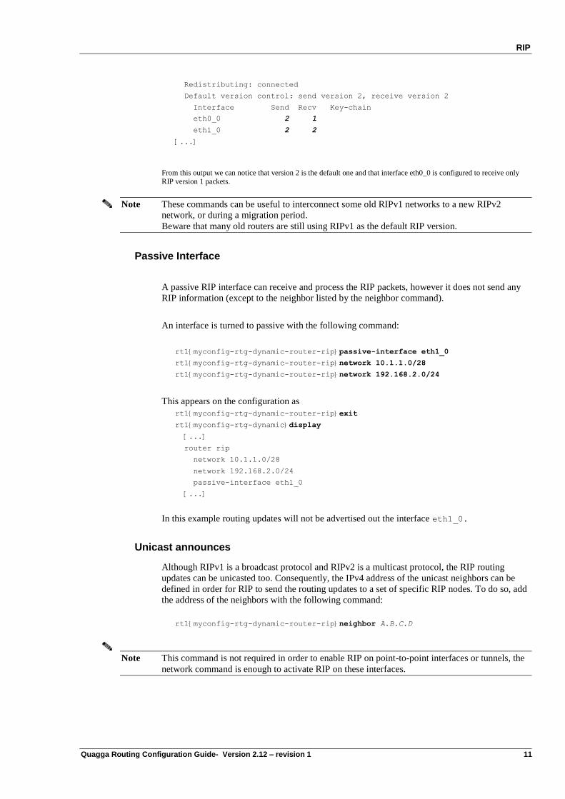
Redistributing: connected
Default version control: send version 2, receive version 2
Interface Send Recv Key-chain
eth0_0 2 1
eth1_0 2 2
[...]
From this output we can notice that version 2 is the default one and that interface eth0_0 is configured to receive only RIP version 1 packets.
Note These commands can be useful to interconnect some old RIPv1 networks to a new RIPv2
network, or during a migration period.
Beware that many old routers are still using RIPv1 as the default RIP version.
Passive Interface
A passive RIP interface can receive and process the RIP packets, however it does not send any
RIP information (except to the neighbor listed by the neighbor command).
An interface is turned to passive with the following command:
rt1{myconfig-rtg-dynamic-router-rip}passive-interface eth1_0
rt1{myconfig-rtg-dynamic-router-rip}network 10.1.1.0/28
rt1{myconfig-rtg-dynamic-router-rip}network 192.168.2.0/24
This appears on the configuration as
rt1{myconfig-rtg-dynamic-router-rip}exit
rt1{myconfig-rtg-dynamic}display
[...]
router rip
network 10.1.1.0/28
network 192.168.2.0/24
passive-interface eth1_0
[...]
In this example routing updates will not be advertised out the interface eth1_0.
Unicast announces
Although RIPv1 is a broadcast protocol and RIPv2 is a multicast protocol, the RIP routing
updates can be unicasted too. Consequently, the IPv4 address of the unicast neighbors can be
defined in order for RIP to send the routing updates to a set of specific RIP nodes. To do so, add
the address of the neighbors with the following command:
rt1{myconfig-rtg-dynamic-router-rip}neighbor A.B.C.D
Note This command is not required in order to enable RIP on point-to-point interfaces or tunnels, the
network command is enough to activate RIP on these interfaces.
RIP
12 Quagga Routing Configuration Guide- Version 2.12 – revision 1
Note This command does NOT prevent RIP multicast packet to be sent on an interface. To suppress
any RIP multicast packets, this command must be use jointly with the passive-interface
command
Modify timers
The routing protocols are based on many timers that control the stability of your network and the
time convergence of the algorithms. RIP is based on three timers:
The routing table update in seconds: default 30 s.
The routing information timeout in seconds: default 180 s.
The garbage collection in seconds: default 120 s.
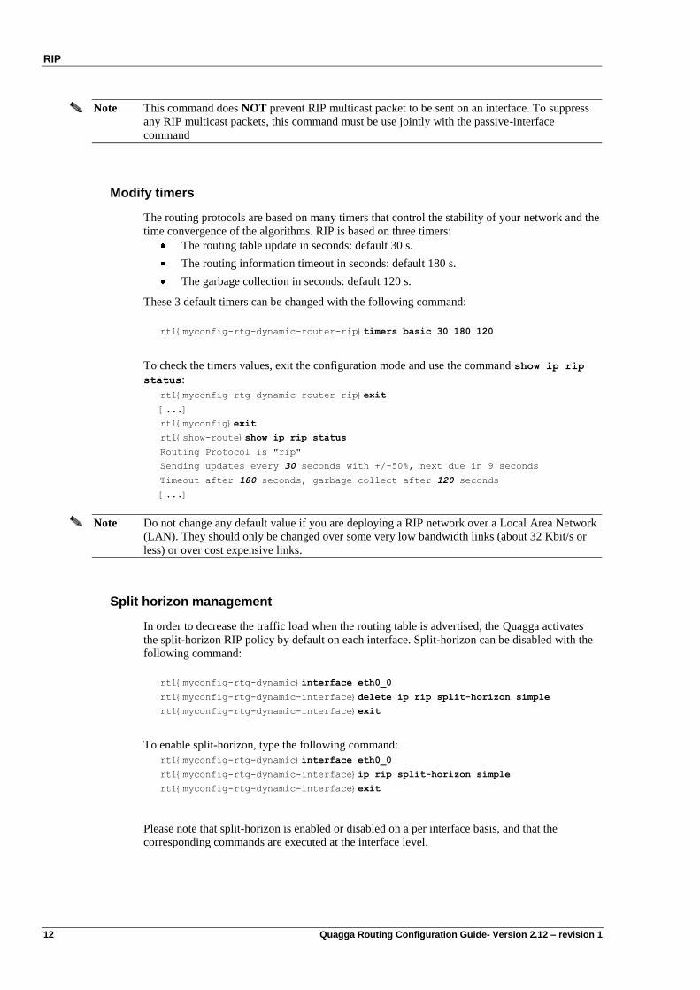
These 3 default timers can be changed with the following command:
rt1{myconfig-rtg-dynamic-router-rip}timers basic 30 180 120
To check the timers values, exit the configuration mode and use the command show ip rip
status:
rt1{myconfig-rtg-dynamic-router-rip}exit
[...]
rt1{myconfig}exit
rt1{show-route}show ip rip status
Routing Protocol is "rip"
Sending updates every 30 seconds with +/-50%, next due in 9 seconds
Timeout after 180 seconds, garbage collect after 120 seconds
[...]
Note Do not change any default value if you are deploying a RIP network over a Local Area Network
(LAN). They should only be changed over some very low bandwidth links (about 32 Kbit/s or
less) or over cost expensive links.
Split horizon management
In order to decrease the traffic load when the routing table is advertised, the Quagga activates
the split-horizon RIP policy by default on each interface. Split-horizon can be disabled with the
following command:
rt1{myconfig-rtg-dynamic}interface eth0_0
rt1{myconfig-rtg-dynamic-interface}delete ip rip split-horizon simple
rt1{myconfig-rtg-dynamic-interface}exit
To enable split-horizon, type the following command:
rt1{myconfig-rtg-dynamic}interface eth0_0
rt1{myconfig-rtg-dynamic-interface}ip rip split-horizon simple
rt1{myconfig-rtg-dynamic-interface}exit
Please note that split-horizon is enabled or disabled on a per interface basis, and that the
corresponding commands are executed at the interface level.
RIP
Quagga Routing Configuration Guide- Version 2.12 – revision 1 13
Note Split-horizon should be disabled when many interfaces on a broadcast area do not share the
same connected prefix. In fact, in this case, it is enough to disable split-horizon on the routers
that have the common connected prefixes because it will act as a gateway for the different
connected prefixes.
Split horizon with poisoned reverse
In order to increase the time convergence of the RIP algorithm, the originator routes may be
poisoned. It means that the routes will be announced with an infinite metric (16) via the interface
that should be used for the shortest path. However it increases the traffic load. By default
Quagga does not activate the split-horizon with poisoned reverse path on each interface. It can
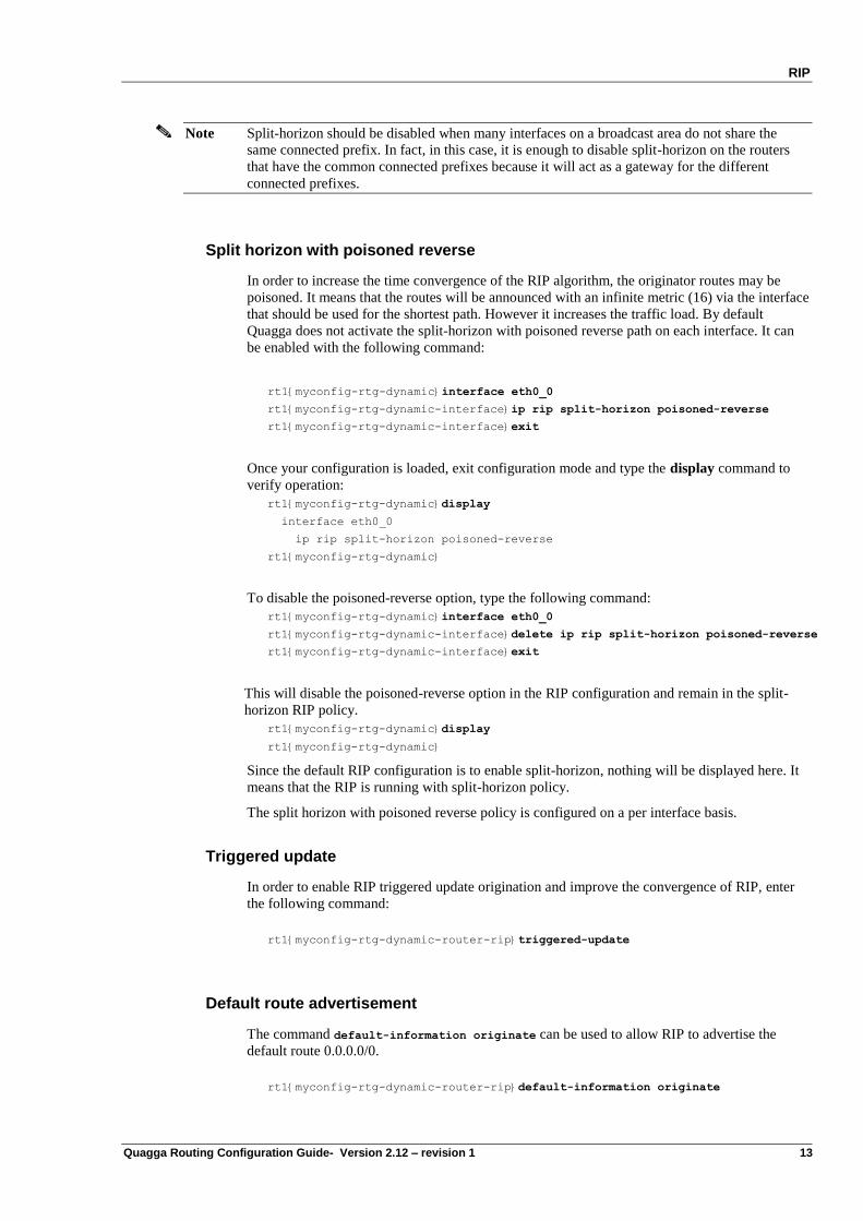
be enabled with the following command:
rt1{myconfig-rtg-dynamic}interface eth0_0
rt1{myconfig-rtg-dynamic-interface}ip rip split-horizon poisoned-reverse
rt1{myconfig-rtg-dynamic-interface}exit
Once your configuration is loaded, exit configuration mode and type the display command to
verify operation:
rt1{myconfig-rtg-dynamic}display
interface eth0_0
ip rip split-horizon poisoned-reverse
rt1{myconfig-rtg-dynamic}
To disable the poisoned-reverse option, type the following command:
rt1{myconfig-rtg-dynamic}interface eth0_0
rt1{myconfig-rtg-dynamic-interface}delete ip rip split-horizon poisoned-reverse
rt1{myconfig-rtg-dynamic-interface}exit
This will disable the poisoned-reverse option in the RIP configuration and remain in the split-
horizon RIP policy.
rt1{myconfig-rtg-dynamic}display
rt1{myconfig-rtg-dynamic}
Since the default RIP configuration is to enable split-horizon, nothing will be displayed here. It
means that the RIP is running with split-horizon policy.
The split horizon with poisoned reverse policy is configured on a per interface basis.
Triggered update
In order to enable RIP triggered update origination and improve the convergence of RIP, enter
the following command:
rt1{myconfig-rtg-dynamic-router-rip}triggered-update
Default route advertisement
The command default-information originate can be used to allow RIP to advertise the
default route 0.0.0.0/0.
rt1{myconfig-rtg-dynamic-router-rip}default-information originate
RIP
14 Quagga Routing Configuration Guide- Version 2.12 – revision 1
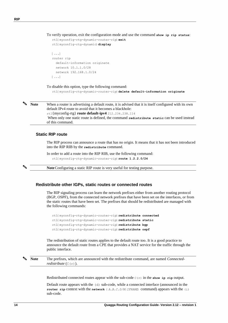
To verify operation, exit the configuration mode and use the command show ip rip status:
rt1{myconfig-rtg-dynamic-router-rip}exit
rt1{myconfig-rtg-dynamic}display
[...]
router rip
default-information originate
network 10.1.1.0/28
network 192.168.1.0/24
[...]
To disable this option, type the following command:
rt1{myconfig-rtg-dynamic-router-rip}delete default-information originate
Note When a router is advertising a default route, it is advised that it is itself configured with its own
default IPv4 route to avoid that it becomes a blackhole:
rt1{myconfig-rtg} route default-ipv4 212.234.238.114
When only one static route is defined, the command redistribute static can be used instead
of this command.
Static RIP route
The RIP process can announce a route that has no origin. It means that it has not been introduced
into the RIP RIB by the redistribute command.
In order to add a route into the RIP RIB, use the following command:
rt1{myconfig-rtg-dynamic-router-rip}route 1.2.2.0/24
Note Configuring a static RIP route is very useful for testing purpose.
Redistribute other IGPs, static routes or connected routes
The RIP signaling process can learn the network prefixes either from another routing protocol
(BGP, OSPF), from the connected network prefixes that have been set on the interfaces, or from
the static routes that have been set. The prefixes that should be redistributed are managed with
the following commands:
rt1{myconfig-rtg-dynamic-router-rip}redistribute connected
rt1{myconfig-rtg-dynamic-router-rip}redistribute static
rt1{myconfig-rtg-dynamic-router-rip}redistribute bgp
rt1{myconfig-rtg-dynamic-router-rip}redistribute ospf
The redistribution of static routes applies to the default route too. It is a good practice to
announce the default route from a CPE that provides a NAT service for the traffic through the
public interface.
Note The prefixes, which are announced with the redistribute command, are named Connected-
redistribute (C(r)).
Redistributed connected routes appear with the sub-code C(r) in the show ip rip output.
Default route appears with the (d) sub-code, while a connected interface (announced in the
router rip context with the network {A.B.C.D/M|IFNAME} command) appears with the (i)
sub-code.
RIP
Quagga Routing Configuration Guide- Version 2.12 – revision 1 15
Please note that if the same prefix is learnt via different means (redistribution, interface or
default) the route learnt via redistribution is the less preferred.
FIB’s RIP administrative distance
When many IGPs and EGPs are provisioning a same active route into the IPv4 FIB, the one
from the preferred routing protocols is selected; for example the static routes are preferred to the
OSPFv2 routes that are preferred to the RIP routes that are preferred to the eBGP routes.
The default RIP distance is 120. This value can be changed with the following command:
rt1{myconfig-rtg-dynamic-router-rip}distance 123
We give here a reminder of the common routing protocols administrative distance:
Routing protocol Administrative
distance
Connected prefixes (routes) 0
Static routes 1
DEP (Delegated Prefixes) 10
BGP (Border Gateway Protocol) 20
OSPFv2 and OSPFv3 110
RIP and RIPng (Routing Information
Protocol)
120
Manage the redistributed metrics
Since the routing protocols are not the same (BGP, static, connected), the associated metrics
cannot be compared, and hence cannot be kept within the RIP advertisements. An arbitrary
distance, which is assimilated to a hop count, can be set with the redistribute SOURCE metric
N command into the RIP dynamic context.
rt1{myconfig-rtg-dynamic-router-rip}redistribute static metric 3
rt1{myconfig-rtg-dynamic-router-rip}redistribute connected metric 2
rt1{myconfig-rtg-dynamic-router-rip}redistribute bgp metric 9
rt1{myconfig-rtg-dynamic-router-rip}redistribute ospf metric 4
Note Due to the maximum RIP metric (16), these commands decrease the size of your network.
The default redistribution metric into RIP is 1.
Please note that when redistributing a routing protocol into RIP, special care must be taken for
the metric control, because not all routing protocols have the same metric. Remember that RIP
uses the hop count as metric.
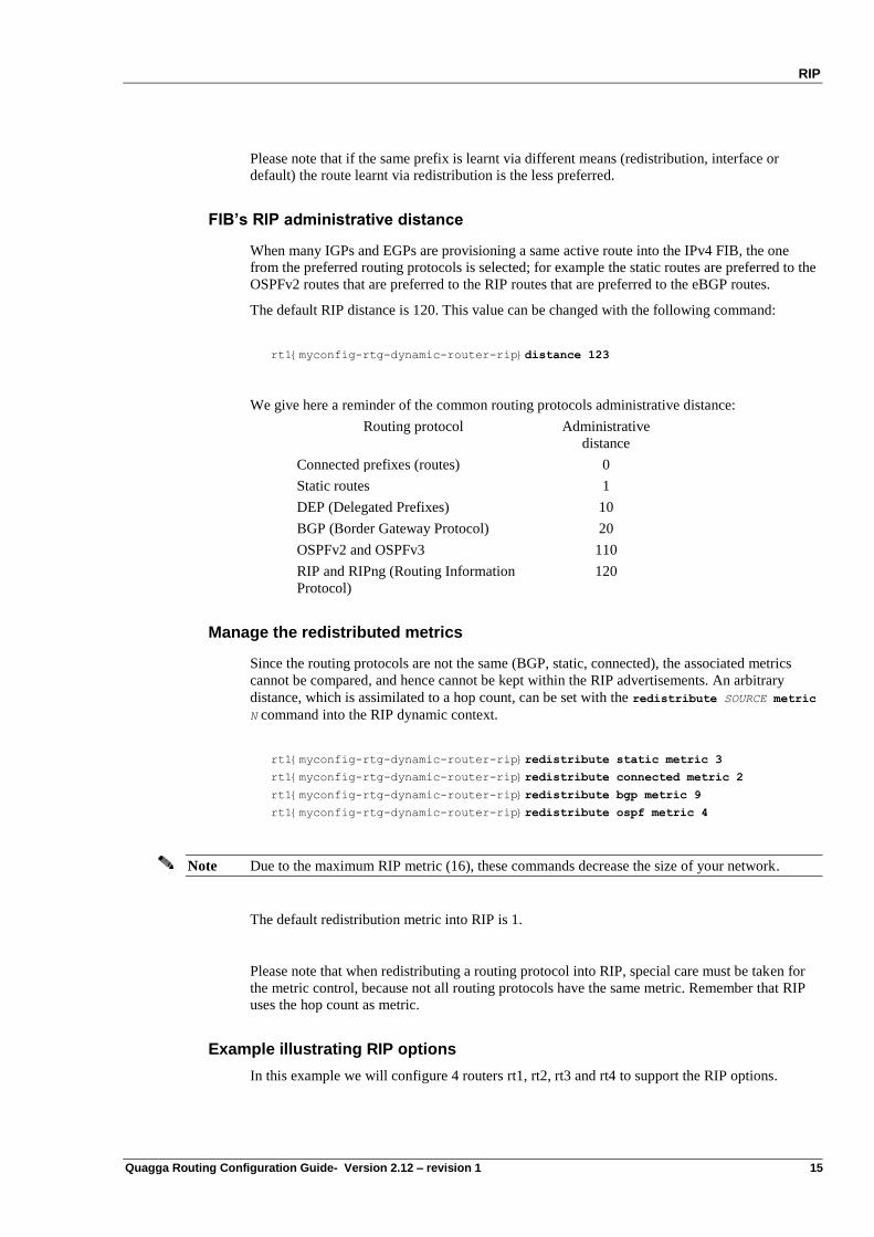
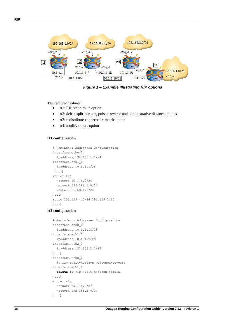
Example illustrating RIP options
In this example we will configure 4 routers rt1, rt2, rt3 and rt4 to support the RIP options.
RIP
16 Quagga Routing Configuration Guide- Version 2.12 – revision 1
Figure 1 – Example illustrating RIP options
The required features:
rt1: RIP static route option
rt2: delete split-horizon, poison-reverse and administrative distance options
rt3: redistribute connected + metric option
rt4: modify timers option
rt1 configuration
# Reminder: Addresses Configuration
interface eth0_0
ipaddress 192.168.1.1/24
interface eth1_0
ipaddress 10.1.1.1/28
[...]
router rip
network 10.1.1.0/28
network 192.168.1.0/24
route 192.168.4.0/24
[...]
route 192.168.4.0/24 192.168.1.25
[...]
rt2 configuration
# Reminder : Addresses Configuration
interface eth0_0
ipaddress 10.1.1.18/28
interface eth1_0
ipaddress 10.1.1.2/28
interface eth2_0
ipaddress 192.168.2.2/24
[...]
interface eth0_0
ip rip split-horizon poisoned-reverse
interface eth1_0
delete ip rip split-horizon simple
[...]
router rip
network 10.1.1.0/27
network 192.168.2.0/24
[...]
RIP
Quagga Routing Configuration Guide- Version 2.12 – revision 1 17
rt3 configuration
# Reminder : Addresses Configuration
interface eth0_0
ipaddress 192.168.3.3/24
interface eth1_0
ipaddress 10.1.1.19/28
[...]
router rip
network 10.1.1.16/28
redistribute connected metric 4
[...]
rt4 configuration
# Reminder : Addresses Configuration
interface eth0_0
ipaddress 172.16.1.4/24
interface eth1_0
ipaddress 10.1.1.20/28
[...]
router rip
network 10.1.1.16/28
network eth0_0
timers basic 30 180 120
[...]
Here is what rt1 RIP RIB and FIB look like:
rt1{show-route}show ip rip
Codes: R - RIP, C - connected, S - Static, O - OSPF, B - BGP
D - DEP
Sub-codes:
(n) - normal, (s) - static, (d) - default, (r) - redistribute,
(i) - interface
Network Next Hop Metric From Tag Time
C(i) 10.1.1.0/28 0.0.0.0 1 self 0
R(n) 10.1.1.16/28 10.1.1.2 2 10.1.1.2 0 02:53
R(n) 172.16.1.0/24 10.1.1.2 3 10.1.1.2 0 02:53
C(i) 192.168.1.0/24 0.0.0.0 1 self 0
R(n) 192.168.2.0/24 10.1.1.2 2 10.1.1.2 0 02:53
R(n) 192.168.3.0/24 10.1.1.2 6 10.1.1.2 0 02:53
R(s) 192.168.4.0/24 0.0.0.0 1 self 0
The 10.1.1.0/28 and 192.168.1.0/24 routes are routes to directly connected interfaces (C(i) flag),
their next hop is consequently rt1 itself and the metric is 1. The 192.168.4.0/24 route is
redistributed from a static route (R(s) flag), its next hop is consequently rt1 itself and the metric
is 1.
The 10.1.1.16/28, 172.16.1.0/24 and 192.168.2.0/24 route were acquired via the RIP protocol
(R(n) flag), their next hop is rt2 and their metrics correspond to the number of hops up to the
destination. The 192.168.3.0/24 route‟s metric is 6 instead of 2, due to rt3 configuration, which
increased the metric by 4.
rt1{show-route}show ip route
RIP
18 Quagga Routing Configuration Guide- Version 2.12 – revision 1
Codes: K - kernel route, C - connected, S - static, R - RIP, O - OSPF,
B - BGP, D - DEP, > - selected route, * - FIB route
C>* 10.1.1.0/28 is directly connected, eth1_0
R>* 10.1.1.16/28 [120/2] via 10.1.1.2, eth1_0, 00:00:16
C>* 127.0.0.0/8 is directly connected, lo0
R>* 172.16.1.0/24 [120/3] via 10.1.1.2, eth1_0, 00:00:16
C>* 192.168.1.0/24 is directly connected, eth0_0
R>* 192.168.2.0/24 [120/2] via 10.1.1.2, eth1_0, 00:00:16
R>* 192.168.3.0/24 [120/6] via 10.1.1.2, eth1_0, 00:00:16
S>* 192.168.4.0/24 [1/0] via 192.168.1.25, eth0_0
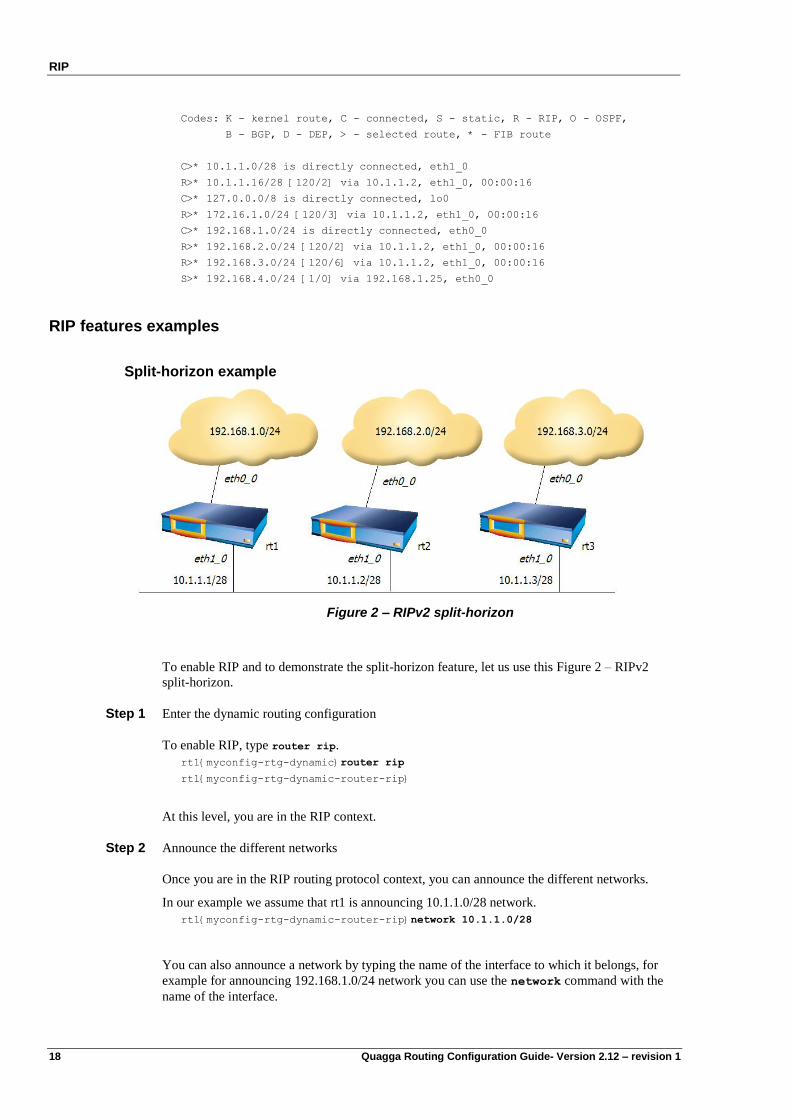
RIP features examples
Split-horizon example
Figure 2 – RIPv2 split-horizon
To enable RIP and to demonstrate the split-horizon feature, let us use this Figure 2 – RIPv2
split-horizon.
Step 1 Enter the dynamic routing configuration
To enable RIP, type router rip.
rt1{myconfig-rtg-dynamic}router rip
rt1{myconfig-rtg-dynamic-router-rip}
At this level, you are in the RIP context.
Step 2 Announce the different networks
Once you are in the RIP routing protocol context, you can announce the different networks.
In our example we assume that rt1 is announcing 10.1.1.0/28 network.
rt1{myconfig-rtg-dynamic-router-rip}network 10.1.1.0/28
You can also announce a network by typing the name of the interface to which it belongs, for
example for announcing 192.168.1.0/24 network you can use the network command with the
name of the interface.
RIP
Quagga Routing Configuration Guide- Version 2.12 – revision 1 19
rt1{myconfig-rtg-dynamic-router-rip}network eth0_0
rt1{myconfig-rtg-dynamic-router-rip}exit
[...]
Please note that when announcing an interface in the network statement, you announce all the
networks to which this interface is attached.
To verify the configuration, exit the configuration and type display :
rt1{myconfig-rtg-dynamic}display
[...]
router rip
network 10.1.1.0/28
network eth0_0
[...]
Step 3 Show routing information
Now RIP is running and RIP does not announce the learnt prefixes on the interfaces from which
they were learnt. This is the default behavior of the Quagga. For example, rt1‟s RIP RIB is:
rt1{show-route}show ip rip
Codes: R - RIP, C - connected, S - Static, O - OSPF, B - BGP
D - DEP
Sub-codes:
(n) - normal, (s) - static, (d) - default, (r) - redistribute,
(i) - interface
Network Next Hop Metric From Tag Time
C(i) 10.1.1.0/28 0.0.0.0 1 self 0
C(i) 192.168.1.0/24 0.0.0.0 1 self 0
R(n) 192.168.2.0/24 10.1.1.2 2 10.1.1.2 0 02:40
R(n) 192.168.3.0/24 10.1.1.3 2 10.1.1.3 0 02:53
By default, with this previous configuration, rt1 does not announce 192.168.2.0/24, neither
192.168.3.0/24 on the eth1_0 interface due to the split-horizon feature. When split-horizon is
disabled, they are announced.
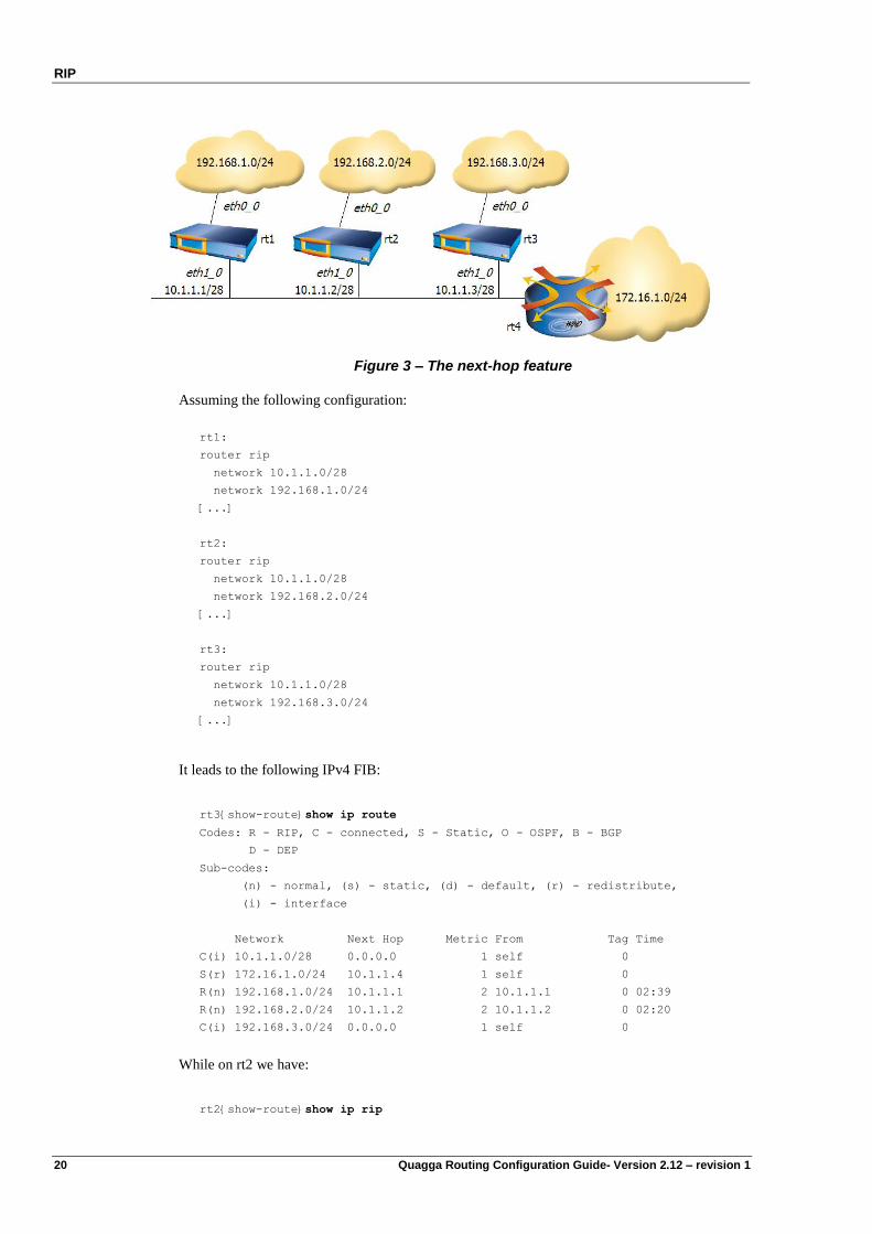
Next-hop option example
When sending a RIP message, the router will if necessary add a next-hop option to the routes it
advertises. This option indicates the gateway via which the router can reach the advertised
destinations. It enables the routers that receive the RIP message to create local shortcuts.
If the next-hop option is not set, then the router that originated the RIP packet is used as the
next-hop.
For example, if rt3 has a static route to the network 172.16.1.0/24 via a gateway – 10.1.1.4 – on
the eth1_0 interface, rt2 and rt1 know that they can directly reach this gateway without sending
packets to rt3, so they conclude that there is a shorter route to network 172.16.1.0/24 via the
10.1.1.4 gateway.
RIP
20 Quagga Routing Configuration Guide- Version 2.12 – revision 1
Figure 3 – The next-hop feature
Assuming the following configuration:
rt1:
router rip
network 10.1.1.0/28
network 192.168.1.0/24
[...]
rt2:
router rip
network 10.1.1.0/28
network 192.168.2.0/24
[...]
rt3:
router rip
network 10.1.1.0/28
network 192.168.3.0/24
[...]
It leads to the following IPv4 FIB:
rt3{show-route}show ip route
Codes: R - RIP, C - connected, S - Static, O - OSPF, B - BGP
D - DEP
Sub-codes:
(n) - normal, (s) - static, (d) - default, (r) - redistribute,
(i) - interface
Network Next Hop Metric From Tag Time
C(i) 10.1.1.0/28 0.0.0.0 1 self 0
S(r) 172.16.1.0/24 10.1.1.4 1 self 0
R(n) 192.168.1.0/24 10.1.1.1 2 10.1.1.1 0 02:39
R(n) 192.168.2.0/24 10.1.1.2 2 10.1.1.2 0 02:20
C(i) 192.168.3.0/24 0.0.0.0 1 self 0
While on rt2 we have:
rt2{show-route}show ip rip
RIP
Quagga Routing Configuration Guide- Version 2.12 – revision 1 21
Codes: R - RIP, C - connected, S - Static, O - OSPF, B - BGP
D - DEP
Sub-codes:
(n) - normal, (s) - static, (d) - default, (r) - redistribute,
(i) - interface
Network Next Hop Metric From Tag Time
C(i) 10.1.1.0/28 0.0.0.0 1 self 0
R(n) 172.16.1.0/24 10.1.1.4 2 10.1.1.3 0 02:45
R(n) 192.168.1.0/24 10.1.1.1 2 10.1.1.1 0 02:46
C(i) 192.168.2.0/24 0.0.0.0 1 self 0
R(n) 192.168.3.0/24 10.1.1.3 2 10.1.1.3 0 02:45
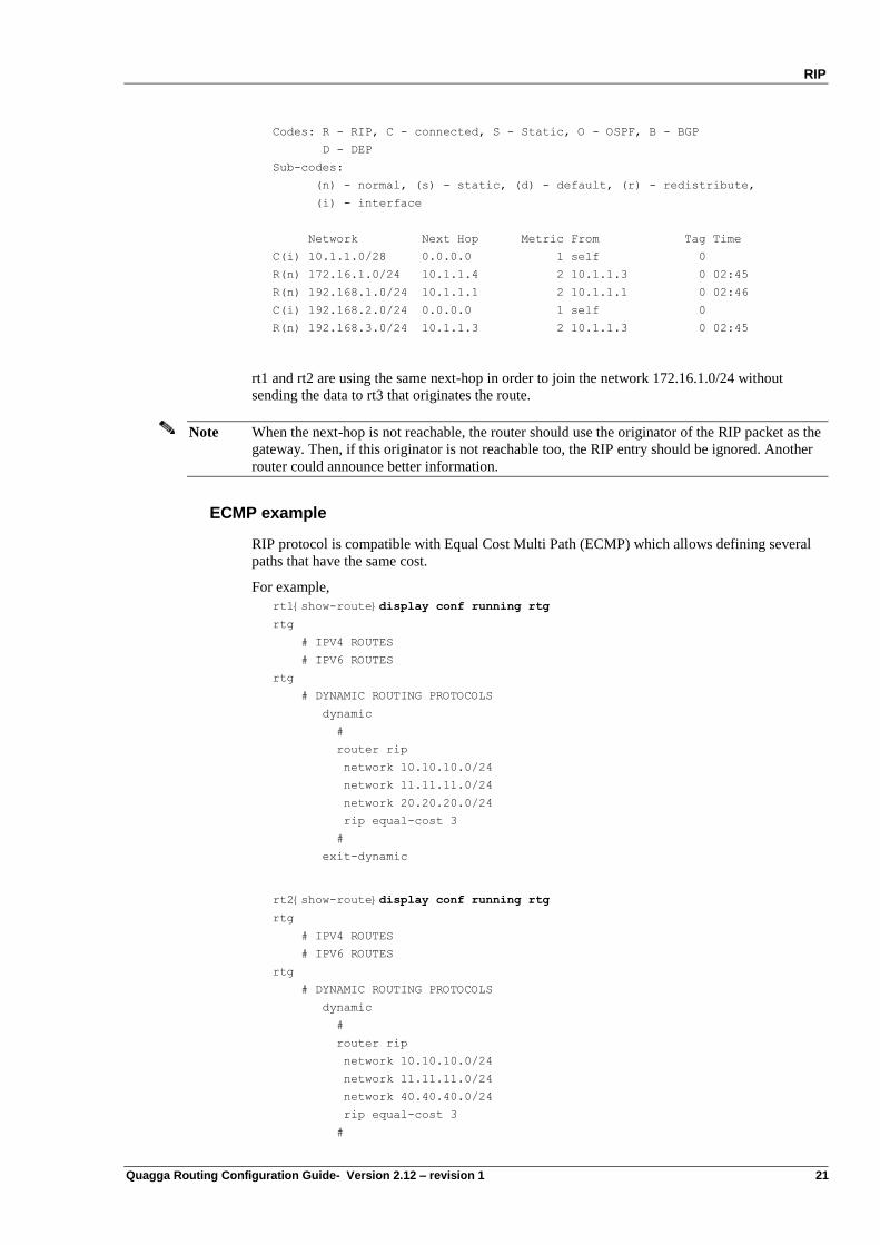
rt1 and rt2 are using the same next-hop in order to join the network 172.16.1.0/24 without
sending the data to rt3 that originates the route.
Note When the next-hop is not reachable, the router should use the originator of the RIP packet as the
gateway. Then, if this originator is not reachable too, the RIP entry should be ignored. Another
router could announce better information.
ECMP example
RIP protocol is compatible with Equal Cost Multi Path (ECMP) which allows defining several
paths that have the same cost.
For example,
rt1{show-route}display conf running rtg
rtg
# IPV4 ROUTES
# IPV6 ROUTES
rtg
# DYNAMIC ROUTING PROTOCOLS
dynamic
#
router rip
network 10.10.10.0/24
network 11.11.11.0/24
network 20.20.20.0/24
rip equal-cost 3
#
exit-dynamic
rt2{show-route}display conf running rtg
rtg
# IPV4 ROUTES
# IPV6 ROUTES
rtg
# DYNAMIC ROUTING PROTOCOLS
dynamic
#
router rip
network 10.10.10.0/24
network 11.11.11.0/24
network 40.40.40.0/24
rip equal-cost 3
#
RIP
22 Quagga Routing Configuration Guide- Version 2.12 – revision 1
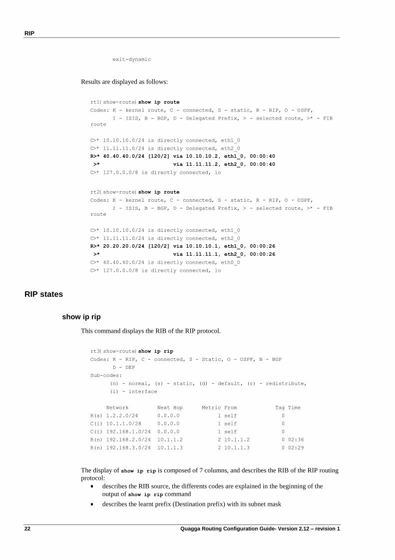
exit-dynamic
Results are displayed as follows:
rt1{show-route}show ip route
Codes: K - kernel route, C - connected, S - static, R - RIP, O - OSPF,
I - ISIS, B - BGP, D - Delegated Prefix, > - selected route, >* - FIB
route
C>* 10.10.10.0/24 is directly connected, eth1_0
C>* 11.11.11.0/24 is directly connected, eth2_0
R>* 40.40.40.0/24 [120/2] via 10.10.10.2, eth1_0, 00:00:40
>* via 11.11.11.2, eth2_0, 00:00:40
C>* 127.0.0.0/8 is directly connected, lo
rt2{show-route}show ip route
Codes: K - kernel route, C - connected, S - static, R - RIP, O - OSPF,
I - ISIS, B - BGP, D - Delegated Prefix, > - selected route, >* - FIB
route
C>* 10.10.10.0/24 is directly connected, eth1_0
C>* 11.11.11.0/24 is directly connected, eth2_0
R>* 20.20.20.0/24 [120/2] via 10.10.10.1, eth1_0, 00:00:26
>* via 11.11.11.1, eth2_0, 00:00:26
C>* 40.40.40.0/24 is directly connected, eth0_0
C>* 127.0.0.0/8 is directly connected, lo
RIP states
show ip rip
This command displays the RIB of the RIP protocol.
rt3{show-route}show ip rip
Codes: R - RIP, C - connected, S - Static, O - OSPF, B - BGP
D - DEP
Sub-codes:
(n) - normal, (s) - static, (d) - default, (r) - redistribute,
(i) - interface
Network Next Hop Metric From Tag Time
R(s) 1.2.2.0/24 0.0.0.0 1 self 0
C(i) 10.1.1.0/28 0.0.0.0 1 self 0
C(i) 192.168.1.0/24 0.0.0.0 1 self 0
R(n) 192.168.2.0/24 10.1.1.2 2 10.1.1.2 0 02:36
R(n) 192.168.3.0/24 10.1.1.3 2 10.1.1.3 0 02:29
The display of show ip rip is composed of 7 columns, and describes the RIB of the RIP routing
protocol:
describes the RIB source, the differents codes are explained in the beginning of the
output of show ip rip command
describes the learnt prefix (Destination prefix) with its subnet mask
RIP
Quagga Routing Configuration Guide- Version 2.12 – revision 1 23
indicates the next hop to this destination (0.0.0.0 means itself).
indicates the hop count to the destination prefix
indicates the router that advertises the destination prefix
this tag normally should be set to 0
the validity time. By default, it is set to 3 minutes when a RIP route is received.
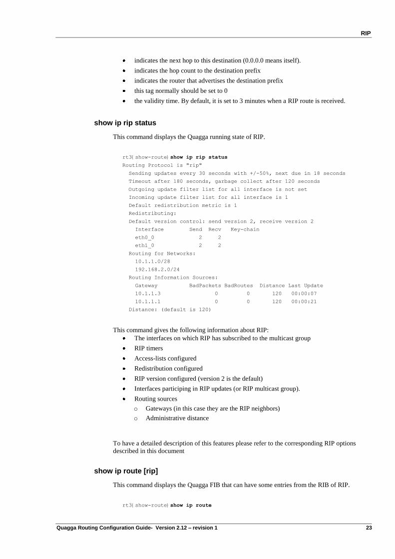
show ip rip status
This command displays the Quagga running state of RIP.
rt3{show-route}show ip rip status
Routing Protocol is "rip"
Sending updates every 30 seconds with +/-50%, next due in 18 seconds
Timeout after 180 seconds, garbage collect after 120 seconds
Outgoing update filter list for all interface is not set
Incoming update filter list for all interface is 1
Default redistribution metric is 1
Redistributing:
Default version control: send version 2, receive version 2
Interface Send Recv Key-chain
eth0_0 2 2
eth1_0 2 2
Routing for Networks:
10.1.1.0/28
192.168.2.0/24
Routing Information Sources:
Gateway BadPackets BadRoutes Distance Last Update
10.1.1.3 0 0 120 00:00:07
10.1.1.1 0 0 120 00:00:21
Distance: (default is 120)
This command gives the following information about RIP:
The interfaces on which RIP has subscribed to the multicast group
RIP timers
Access-lists configured
Redistribution configured
RIP version configured (version 2 is the default)
Interfaces participing in RIP updates (or RIP multicast group).
Routing sources
o Gateways (in this case they are the RIP neighbors)
o Administrative distance
To have a detailed description of this features please refer to the corresponding RIP options
described in this document
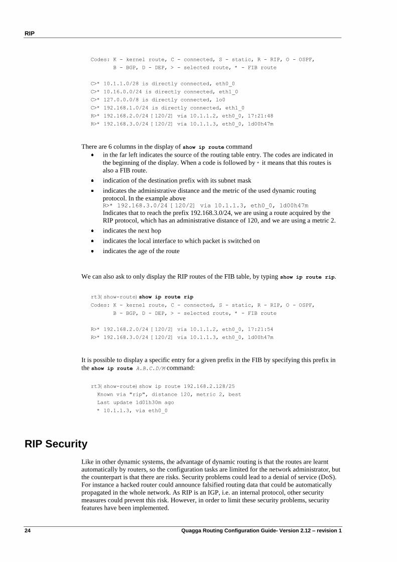
show ip route [rip]
This command displays the Quagga FIB that can have some entries from the RIB of RIP.
rt3{show-route}show ip route
RIP
24 Quagga Routing Configuration Guide- Version 2.12 – revision 1
Codes: K - kernel route, C - connected, S - static, R - RIP, O - OSPF,
B - BGP, D - DEP, > - selected route, * - FIB route
C>* 10.1.1.0/28 is directly connected, eth0_0
C>* 10.16.0.0/24 is directly connected, eth1_0
C>* 127.0.0.0/8 is directly connected, lo0
C>* 192.168.1.0/24 is directly connected, eth1_0
R>* 192.168.2.0/24 [120/2] via 10.1.1.2, eth0_0, 17:21:48
R>* 192.168.3.0/24 [120/2] via 10.1.1.3, eth0_0, 1d00h47m
There are 6 columns in the display of show ip route command
in the far left indicates the source of the routing table entry. The codes are indicated in
the beginning of the display. When a code is followed by * it means that this routes is
also a FIB route.
indication of the destination prefix with its subnet mask
indicates the administrative distance and the metric of the used dynamic routing
protocol. In the example above R>* 192.168.3.0/24 [120/2] via 10.1.1.3, eth0_0, 1d00h47m
Indicates that to reach the prefix 192.168.3.0/24, we are using a route acquired by the
RIP protocol, which has an administrative distance of 120, and we are using a metric 2.
indicates the next hop
indicates the local interface to which packet is switched on
indicates the age of the route
We can also ask to only display the RIP routes of the FIB table, by typing show ip route rip.
rt3{show-route}show ip route rip
Codes: K - kernel route, C - connected, S - static, R - RIP, O - OSPF,
B - BGP, D - DEP, > - selected route, * - FIB route
R>* 192.168.2.0/24 [120/2] via 10.1.1.2, eth0_0, 17:21:54
R>* 192.168.3.0/24 [120/2] via 10.1.1.3, eth0_0, 1d00h47m
It is possible to display a specific entry for a given prefix in the FIB by specifying this prefix in
the show ip route A.B.C.D/M command:
rt3{show-route}show ip route 192.168.2.128/25
Known via "rip", distance 120, metric 2, best
Last update 1d01h30m ago
* 10.1.1.3, via eth0_0
RIP Security
Like in other dynamic systems, the advantage of dynamic routing is that the routes are learnt
automatically by routers, so the configuration tasks are limited for the network administrator, but
the counterpart is that there are risks. Security problems could lead to a denial of service (DoS).
For instance a hacked router could announce falsified routing data that could be automatically
propagated in the whole network. As RIP is an IGP, i.e. an internal protocol, other security
measures could prevent this risk. However, in order to limit these security problems, security
features have been implemented.
RIP
Quagga Routing Configuration Guide- Version 2.12 – revision 1 25
In this context, the advantage of RIPv2 compared to RIPv1 is that the former allows to
authenticate routing information when they are transmitted between routers. Only authenticated
data are allowed to be used by routers.
RIP Authentication
RIP‟s security is based on authentication with a shared secret that can be transmitted to a
broadcast area. RIPv2 supports the two authentication methods: plain-text authentication and
MD5 (Message Digest 5) authentication. The authentication is interface specific (scope). It
means that different authentications can be defined according to the RIP interfaces. For both
authentication methods (plain text or MD5), an interface specific shared secret has to be defined.
The authentication keys are shared and must be the same between neighbors.
Please note that this feature is supported in RIPv2 only. Plain text authentication is the default
setting in every RIPv2 packet. Encrypted authentication is based on the MD5 algorithm. In this
mode of authentication, the routing update carries a 128-bit message that includes the password
encrypted by the MD5 algorithm. The transmitted routing information remains in clear text.
Except to limit error configurations consequences where a clear text password may be enough,
MD5 authentication is obviously advised for security reasons.
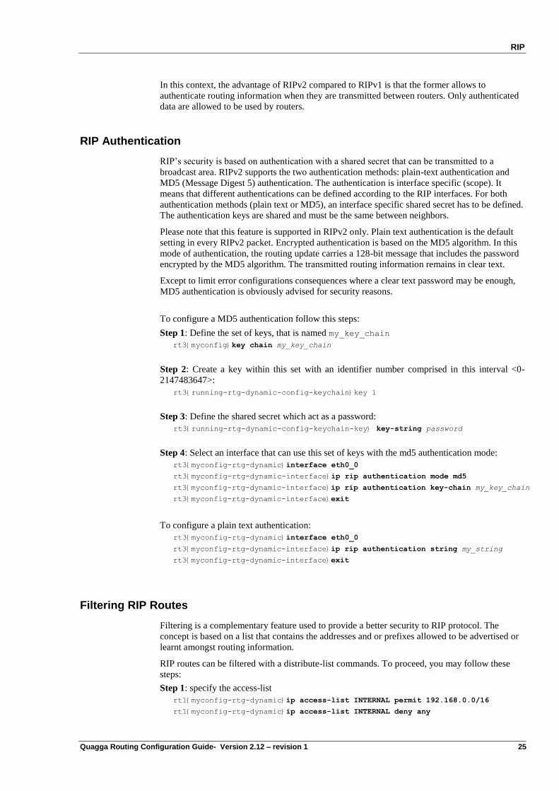
To configure a MD5 authentication follow this steps:
Step 1: Define the set of keys, that is named my_key_chain
rt3{myconfig}key chain my_key_chain
Step 2: Create a key within this set with an identifier number comprised in this interval <0-
2147483647>:
rt3{running-rtg-dynamic-config-keychain}key 1
Step 3: Define the shared secret which act as a password:
rt3{running-rtg-dynamic-config-keychain-key} key-string password
Step 4: Select an interface that can use this set of keys with the md5 authentication mode:
rt3{myconfig-rtg-dynamic}interface eth0_0
rt3{myconfig-rtg-dynamic-interface}ip rip authentication mode md5
rt3{myconfig-rtg-dynamic-interface}ip rip authentication key-chain my_key_chain
rt3{myconfig-rtg-dynamic-interface}exit
To configure a plain text authentication:
rt3{myconfig-rtg-dynamic}interface eth0_0
rt3{myconfig-rtg-dynamic-interface}ip rip authentication string my_string
rt3{myconfig-rtg-dynamic-interface}exit
Filtering RIP Routes
Filtering is a complementary feature used to provide a better security to RIP protocol. The
concept is based on a list that contains the addresses and or prefixes allowed to be advertised or
learnt amongst routing information.
RIP routes can be filtered with a distribute-list commands. To proceed, you may follow these
steps:
Step 1: specify the access-list
rt1{myconfig-rtg-dynamic}ip access-list INTERNAL permit 192.168.0.0/16
rt1{myconfig-rtg-dynamic}ip access-list INTERNAL deny any
RIP
26 Quagga Routing Configuration Guide- Version 2.12 – revision 1
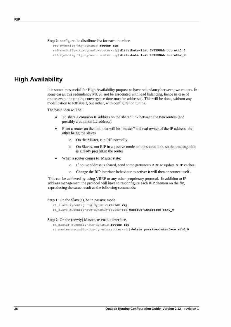
Step 2: configure the distribute-list for each interface
rt1{myconfig-rtg-dynamic}router rip
rt1{myconfig-rtg-dynamic-router-rip}distribute-list INTERNAL out eth0_0
rt1{myconfig-rtg-dynamic-router-rip}distribute-list INTERNAL out eth2_0
High Availability
It is sometimes useful for High Availability purpose to have redundancy between two routers. In
some cases, this redundancy MUST not be associated with load balancing, hence in case of
router swap, the routing convergence time must be addressed. This will be done, without any
modification to RIP itself, but rather, with configuration tuning.
The basic idea will be:
To share a common IP address on the shared link between the two routers (and
possibly a common L2 address).
Elect a router on the link, that will be “master” and real owner of the IP address, the
other being the slaves
o On the Master, run RIP normally
o On Slaves, run RIP in a passive mode on the shared link, so that routing table
is already present in the router
When a router comes to Master state:
o If no L2 address is shared, send some gratuitous ARP to update ARP caches.
o Change the RIP interface behaviour to active: it will then announce itself .
This can be achieved by using VRRP or any other proprietary protocol. In addition to IP
address management the protocol will have to re-configure each RIP daemon on the fly,
reproducing the same result as the following commands:
Step 1: On the Slave(s), be in passive mode
rt_slave{myconfig-rtg-dynamic}router rip
rt_slave{myconfig-rtg-dynamic-router-rip}passive-interface eth0_0
Step 2: On the (newly) Master, re-enable interface,
rt_master{myconfig-rtg-dynamic}router rip
rt_master{myconfig-rtg-dynamic-router-rip}delete passive-interface eth0_0
Quagga Routing Configuration Guide – Version 2.12 – revision 1 27
Chapter 4 OSPFv2
Introduction
OSPF (Open Shortest Path First) is the most known routing protocol among the family of so
called Link State routing protocols. The OSPF algorithm is based on the Dijkstra algorithm.
OSPF was developed by the IETF in 1988. It is described in RFC 2328 (this RFC obsoletes the
RFC 2178). OSPFv2 was designed as an Interior Gateway Protocol (IGP) which addresses
issues like scalability and convergence.
In order to understand OSPF advantages, it is common to compare it to the RIP routing protocol
(which is a distance vector routing protocol). Compared to RIP, OSPF has the following
advantages:
OSPF is scalable, there is no hop count limitation, while RIP is limited to 15,
As a link state protocol, OSPF converges very rapidly in comparison to RIP (which is a
Distance Vector protocol),
OSPF introduces the notion of PATH cost, while RIP only considers the cost in term of
hop count,
OSPF networks can be large and complex. This is possible thanks to the concept of
OSPF areas. RIP doesn‟t offer this facility.
OSPF terminology
It is important to understand the OSPF terminology. In this paragraph we will give the most
important concepts. Please refer to RFC 2328 for a full description of the OSPF algorithm.
Link: An interface or router,
Link state: The status of the link,
Cost: The cost of the link, which mainly depends on the speed and bandwidth,
Area: Collection of networks or routers that have the same area identifier. Note
that within an area, each router has the same link-state information,
Designated router (DR), Designated router backup (Backup), Designated router other
(DROther):
Router designated by the others to represent a network.
OSPFv2
28 Quagga Routing Configuration Guide- Version 2.12 – revision 1
OSPF operation
The OSPF operation is based on the Dijkstra algorithm. The detailed description of this
mechanism in a single area or in multiple areas is out of the scope of this document, please refer
to RFC 2328.
OSPF runs directly over IP and uses protocol number 89.
OSPF configuration in a single area
To configure OSPF in a single area environnement, follow these steps.
Enable OSPF
It can be enabled via the following virtual terminal commands:
...
rt1{}edit conf myconfig
rt1{myconfig}rtg
rt1{myconfig-rtg}dynamic
rt1{myconfig-rtg-dynamic}router ospf
rt1{myconfig-rtg-dynamic-router-ospf}
In the same way, to disable OSPF, type the following command:
rt1{myconfig-rtg-dynamic}delete router ospf
Configure OSPF networks (Mandatory)
To activate OSPF on one or more network interfaces, type the following command:
rt1{myconfig-rtg-dynamic-router-ospf}network a.b.c.d/M area area-id
or
rt1{myconfig-rtg-dynamic-router-ospf}network ifname area area-id
Where:
a.b.c.d/M is a network prefix. OSPF will be enabled on all network interfaces whose
address and network mask is included into this prefix, and will announce a
link connected to a stub or transit network defined by the interface address
and prefix.
ifname is the name of a network interface. OSPF will be enabled on the network
interface with this name (ifname may be a simple regular expression, e.g.
ppp*) and will announce links connected to all stub networks defined by
addresses and prefixes configured on this interface. This command can also
enable OSPF on an unnumbered interface. In this later case, OSPF will
announce an unnumbered link instead.
area-id is a 32 bit id by which an OSPF area is identified. It may be represented as
a decimal value (e.g. 0) or as a dotted-decimal IPv4 address (e.g. 0.0.0.0).
Point-to-point interfaces
There is a special handling for point-to-point interfaces:
OSPFv2
Quagga Routing Configuration Guide- Version 2.12 – revision 1 29
Point-to-point interfaces are configured with IPv4 endpoints (a local and peer address pair)
if prefix length is 32: OSPF will advertise a link to the stub network remote@/32 (link
type 3). OSPF can be enabled on this interface with:
o network remote@/32 (a.b.c.d/M form)
o network ifname
if prefix length is < 32: OSPF will announce a link to the stub network local@/M (link
type 3). OSPF can be enabled on this interface with:
o network local@/M (a.b.c.d/M form)
o network remote@/32 (a.b.c.d/M form)
o network ifname
Unnumbered point-to-point interfaces (interfaces with no IPv4 address):
OSPF will announce a link to the point-to-point interface referenced by ifindex/0 (link
type 1). OSPF can only be enabled on these interfaces with:
o network ifname
Point-to-point Interfaces with only an IPv4 local address and prefix length:
These interfaces are handled like broadcast interfaces.
Note The network ifname form supports simple regular expressions for interface names: a star *
stands for any leading integer.
For instance, ctu* matches ctu0, ctu1 and ctu234, but neither ctu_ppp0 nor ctu.
If several network commands overlap (e.g. ctu* and ctu2), they must specify the same
area-id, otherwise the result is undefined.
Verifying OSPF configuration
The following commands can be used to verify OSPF operation.
This command describes the global OSPF parameters (timers, area, router-id, etc.):
rt1{show-route}show ip ospf
This command dumps the OSPFv2 RIB:
rt1{show-route}show ip ospf route
This command displays OSPF configuration for the specified interface:
rt1{show-route}show ip ospf interface ifname
This command displays the state of the relations with the neighbors:
rt1{show-route}show ip ospf neighbor [detail]
It is possible to display information for a subset of neighbors:
rt1{show-route}show ip ospf neighbor neighbor-id [detail]
It is possible to display the details for all the neighbors on a specific interface:
rt1{show-route}show ip ospf neighbor interface interface-addr [detail]
This command displays the OSPFv2 Link-State databases and provides the information about
LSAs:
rt1{show-route}show ip ospf database [param]
Where param is one of the following value:
asbr-summary ASBR summary link states
OSPFv2
30 Quagga Routing Configuration Guide- Version 2.12 – revision 1
external External link states
network Network link states
router Router link states
summary Network summary link states
nssa-external NSSA external link state
max-age LSAs in MaxAge list
self-originate Self-originated link states
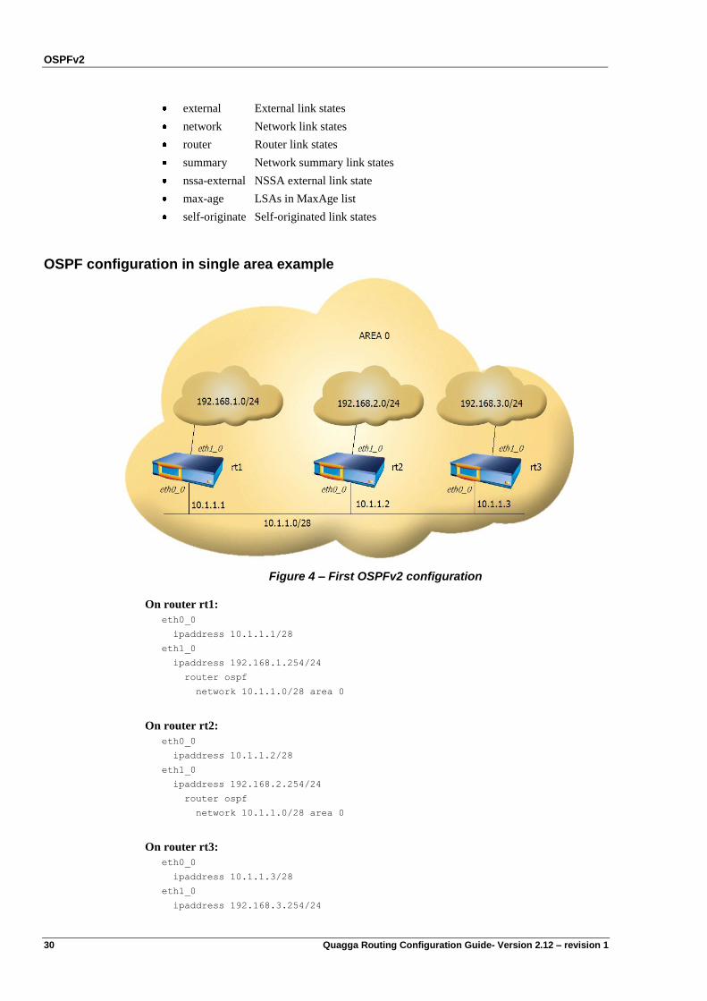
OSPF configuration in single area example
Figure 4 – First OSPFv2 configuration
On router rt1:
eth0_0
ipaddress 10.1.1.1/28
eth1_0
ipaddress 192.168.1.254/24
router ospf
network 10.1.1.0/28 area 0
On router rt2:
eth0_0
ipaddress 10.1.1.2/28
eth1_0
ipaddress 192.168.2.254/24
router ospf
network 10.1.1.0/28 area 0
On router rt3:
eth0_0
ipaddress 10.1.1.3/28
eth1_0
ipaddress 192.168.3.254/24
OSPFv2
Quagga Routing Configuration Guide- Version 2.12 – revision 1 31
router ospf
network 10.1.1.0/28 area 0
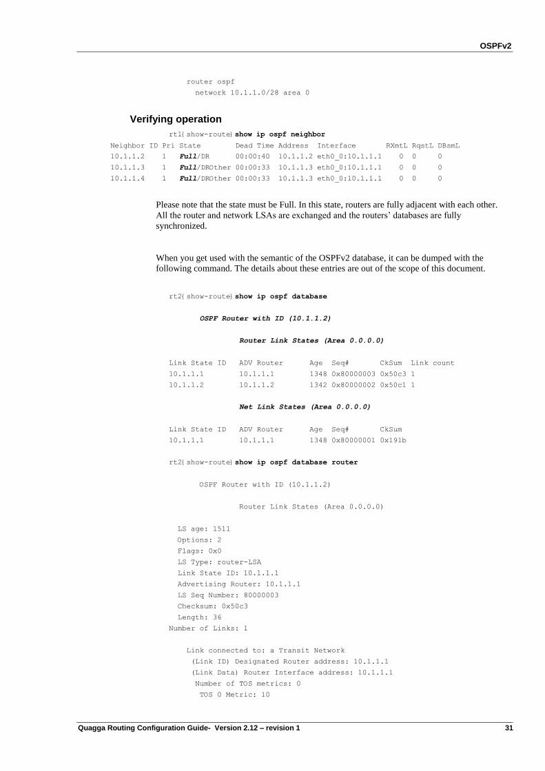
Verifying operation
rt1{show-route}show ip ospf neighbor
Neighbor ID Pri State Dead Time Address Interface RXmtL RqstL DBsmL
10.1.1.2 1 Full/DR 00:00:40 10.1.1.2 eth0_0:10.1.1.1 0 0 0
10.1.1.3 1 Full/DROther 00:00:33 10.1.1.3 eth0_0:10.1.1.1 0 0 0
10.1.1.4 1 Full/DROther 00:00:33 10.1.1.3 eth0_0:10.1.1.1 0 0 0
Please note that the state must be Full. In this state, routers are fully adjacent with each other.
All the router and network LSAs are exchanged and the routers‟ databases are fully
synchronized.
When you get used with the semantic of the OSPFv2 database, it can be dumped with the
following command. The details about these entries are out of the scope of this document.
rt2{show-route}show ip ospf database
OSPF Router with ID (10.1.1.2)
Router Link States (Area 0.0.0.0)
Link State ID ADV Router Age Seq# CkSum Link count
10.1.1.1 10.1.1.1 1348 0x80000003 0x50c3 1
10.1.1.2 10.1.1.2 1342 0x80000002 0x50c1 1
Net Link States (Area 0.0.0.0)
Link State ID ADV Router Age Seq# CkSum
10.1.1.1 10.1.1.1 1348 0x80000001 0x191b
rt2{show-route}show ip ospf database router
OSPF Router with ID (10.1.1.2)
Router Link States (Area 0.0.0.0)
LS age: 1511
Options: 2
Flags: 0x0
LS Type: router-LSA
Link State ID: 10.1.1.1
Advertising Router: 10.1.1.1
LS Seq Number: 80000003
Checksum: 0x50c3
Length: 36
Number of Links: 1
Link connected to: a Transit Network
(Link ID) Designated Router address: 10.1.1.1
(Link Data) Router Interface address: 10.1.1.1
Number of TOS metrics: 0
TOS 0 Metric: 10
OSPFv2
32 Quagga Routing Configuration Guide- Version 2.12 – revision 1
Link connected to: a Transit Network
(Link ID) Designated Router address: 10.1.1.1
(Link Data) Router Interface address: 10.1.1.2
Number of TOS metrics: 0
TOS 0 Metric: 10
.....
.....
Configuring OSPF options
The OSPFv2 routing protocol is very rich and gives many optional configuration options. The
Quagga implementation covers a large set of these options. We will cover the most important
options in this paragraph.
OSPF router-id
The OSPF router-id is a unique 32 bit identifier for the router in the OSPF protocol. By default,
the OSPF daemon chooses one of its configured IPv4 address as its router-id. The administrator
can manually set the router-id:
rt1{myconfig-rtg-dynamic-interface}ospf router-id A.B.C.D
OSPF cost
The OSPF cost is a number from 1 to 65535 which assigns a cost to an OSPF interface. The path
cost is the total of the costs assigned to all outbound interfaces of OSPF routers on a path from a
source to a destination.
To configure the OSPF cost on a given interface, type the following command:
rt1{myconfig-rtg-dynamic-interface}ip ospf cost COST
This command, executed at the interface level, sets the interface output cost. Default value is 1.
OSPF priority
rt1{myconfig-rtg-dynamic-interface}ip ospf priority PRIORITY
Sets interface Router Priority for election of Designated Router. Default value is 1. Set value to
0 to avoid the router is elected as DR. Setting higher value, the router will be more eligible to
DR.
This command is executed at the interface level.
OSPF hello interval
rt1{myconfig-rtg-dynamic-interface}ip ospf hello-interval INTERVAL
Sets interface Hello Interval in seconds. Default value is 40.
This command is executed at the interface level.
OSPF transmit-delay
rt1{myconfig-rtg-dynamic-interface}ip ospf transmit-delay DELAY
OSPFv2
Quagga Routing Configuration Guide- Version 2.12 – revision 1 33
Sets interface Inf-Trans-Delay in seconds. Default value is 1.
This command is executed at the interface level.
OSPF route summarization
This option enables to aggregate several prefixes in one advertisement, this option will be
studied in detail in the multi-area paragraph.
Configuring OSPF in multiple areas
The need for using multiple areas is dictated by scalability issues. A single area OSPF network
with many routers implies frequent SPF calculations, large routing tables, large link-state tables,
and so on…
The design of the OSPF protocol is hierarchical, that is why OSPF scales well. OSPFv2 achieves
this through the use of many areas.
Prior to seeing how OSPF uses the multi-area concept, it is necessary to understand the
following concepts: type of OSPF areas and routers, and type of Link-state advertisements.
OSPF area type
An OSPF area is characterized by the type or routing information it receives. OSPF area types
are:
Standard area: normal OSPF area
Backbone area: in a multi-area environnement, it is the transit area to which all other
areas are connected (area 0)
Stub area: routers in this area accept routing information only from OSPF routers
Totally stubby area: Stub area that does not accept summarization from another OSPF router
OSPF router type
Internal router: router having all its interfaces in a single area
Backbone router: router having at least one interface in the backbone area
Area Border router (ABR):
router having at least one interface in one area and another interface in a
different area
Autonomous System Boundary Router (ASBR):
router having one interface in a non-OSPF network, and another interface
in an OSPF network.
OSPF Link-state type
Type 1: this is a router link entry
Type 2: this is a network link entry generated by DR
Type 3: this is an inter-area summary link generated by ABR
OSPFv2
34 Quagga Routing Configuration Guide- Version 2.12 – revision 1
Type 4: this LSA provides information in order to reach the ASBR
Type 5: this is an external prefix generated by the ASBR, which imports routes from other
protocols (RIP, BGP4, static routes…)
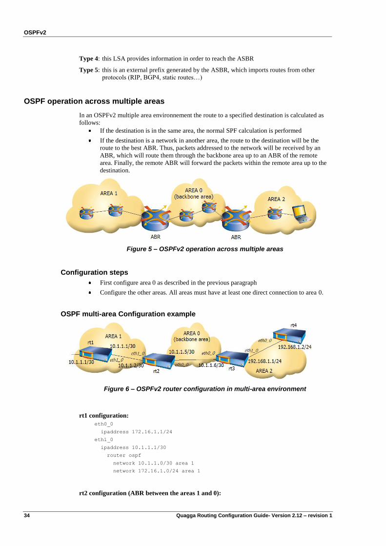
OSPF operation across multiple areas
In an OSPFv2 multiple area environnement the route to a specified destination is calculated as
follows:
If the destination is in the same area, the normal SPF calculation is performed
If the destination is a network in another area, the route to the destination will be the
route to the best ABR. Thus, packets addressed to the network will be received by an
ABR, which will route them through the backbone area up to an ABR of the remote
area. Finally, the remote ABR will forward the packets within the remote area up to the
destination.
Figure 5 – OSPFv2 operation across multiple areas
Configuration steps
First configure area 0 as described in the previous paragraph
Configure the other areas. All areas must have at least one direct connection to area 0.
OSPF multi-area Configuration example
Figure 6 – OSPFv2 router configuration in multi-area environment
rt1 configuration:
eth0_0
ipaddress 172.16.1.1/24
eth1_0
ipaddress 10.1.1.1/30
router ospf
network 10.1.1.0/30 area 1
network 172.16.1.0/24 area 1
rt2 configuration (ABR between the areas 1 and 0):
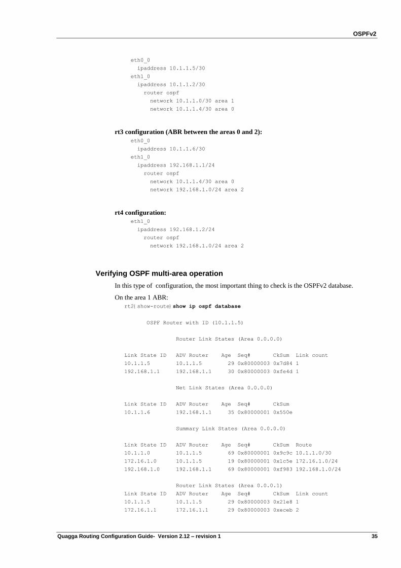
OSPFv2
Quagga Routing Configuration Guide- Version 2.12 – revision 1 35
eth0_0
ipaddress 10.1.1.5/30
eth1_0
ipaddress 10.1.1.2/30
router ospf
network 10.1.1.0/30 area 1
network 10.1.1.4/30 area 0
rt3 configuration (ABR between the areas 0 and 2):
eth0_0
ipaddress 10.1.1.6/30
eth1_0
ipaddress 192.168.1.1/24
router ospf
network 10.1.1.4/30 area 0
network 192.168.1.0/24 area 2
rt4 configuration:
eth1_0
ipaddress 192.168.1.2/24
router ospf
network 192.168.1.0/24 area 2
Verifying OSPF multi-area operation
In this type of configuration, the most important thing to check is the OSPFv2 database.
On the area 1 ABR:
rt2{show-route}show ip ospf database
OSPF Router with ID (10.1.1.5)
Router Link States (Area 0.0.0.0)
Link State ID ADV Router Age Seq# CkSum Link count
10.1.1.5 10.1.1.5 29 0x80000003 0x7d84 1
192.168.1.1 192.168.1.1 30 0x80000003 0xfe4d 1
Net Link States (Area 0.0.0.0)
Link State ID ADV Router Age Seq# CkSum
10.1.1.6 192.168.1.1 35 0x80000001 0x550e
Summary Link States (Area 0.0.0.0)
Link State ID ADV Router Age Seq# CkSum Route
10.1.1.0 10.1.1.5 69 0x80000001 0x9c9c 10.1.1.0/30
172.16.1.0 10.1.1.5 19 0x80000001 0x1c5e 172.16.1.0/24
192.168.1.0 192.168.1.1 69 0x80000001 0xf983 192.168.1.0/24
Router Link States (Area 0.0.0.1)
Link State ID ADV Router Age Seq# CkSum Link count
10.1.1.5 10.1.1.5 29 0x80000003 0x21e8 1
172.16.1.1 172.16.1.1 29 0x80000003 0xeceb 2
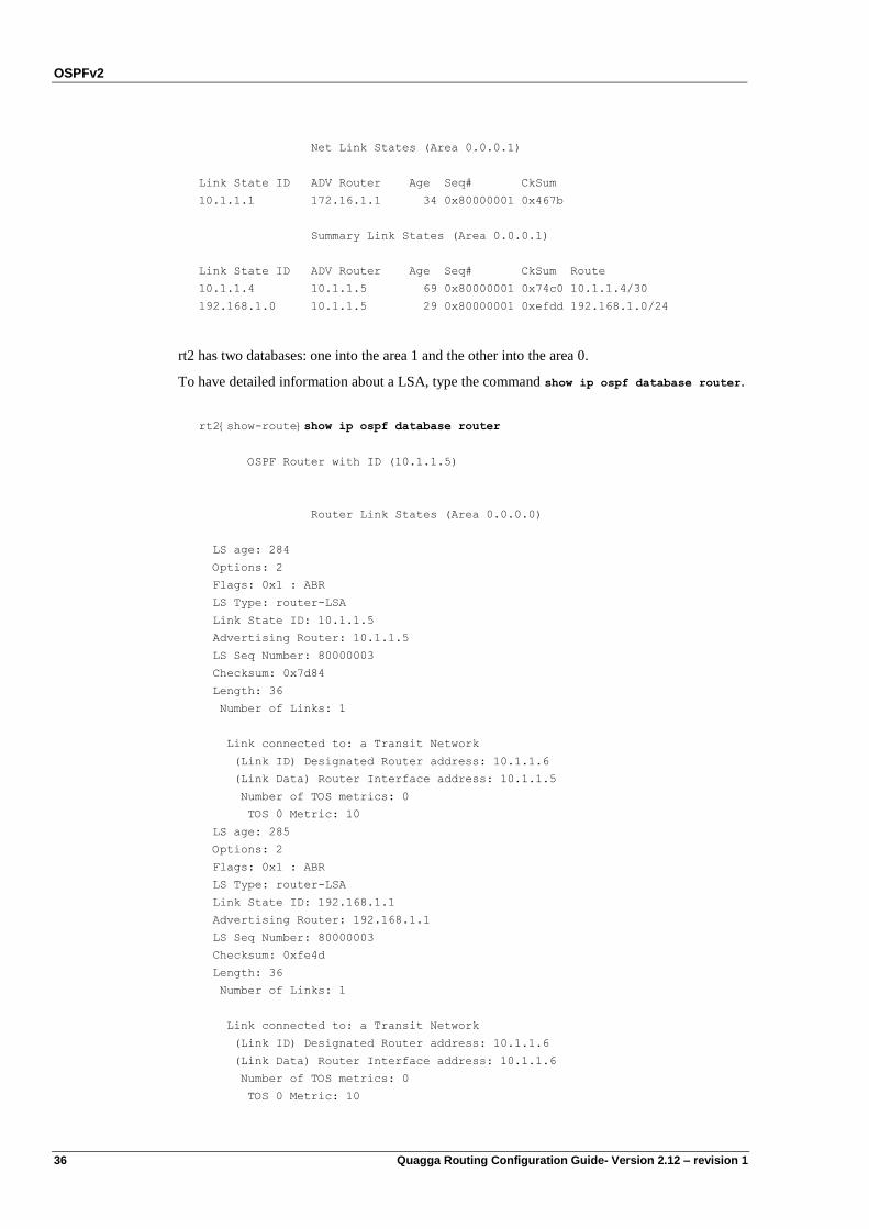
OSPFv2
36 Quagga Routing Configuration Guide- Version 2.12 – revision 1
Net Link States (Area 0.0.0.1)
Link State ID ADV Router Age Seq# CkSum
10.1.1.1 172.16.1.1 34 0x80000001 0x467b
Summary Link States (Area 0.0.0.1)
Link State ID ADV Router Age Seq# CkSum Route
10.1.1.4 10.1.1.5 69 0x80000001 0x74c0 10.1.1.4/30
192.168.1.0 10.1.1.5 29 0x80000001 0xefdd 192.168.1.0/24
rt2 has two databases: one into the area 1 and the other into the area 0.
To have detailed information about a LSA, type the command show ip ospf database router.
rt2{show-route}show ip ospf database router
OSPF Router with ID (10.1.1.5)
Router Link States (Area 0.0.0.0)
LS age: 284
Options: 2
Flags: 0x1 : ABR
LS Type: router-LSA
Link State ID: 10.1.1.5
Advertising Router: 10.1.1.5
LS Seq Number: 80000003
Checksum: 0x7d84
Length: 36
Number of Links: 1
Link connected to: a Transit Network
(Link ID) Designated Router address: 10.1.1.6
(Link Data) Router Interface address: 10.1.1.5
Number of TOS metrics: 0
TOS 0 Metric: 10
LS age: 285
Options: 2
Flags: 0x1 : ABR
LS Type: router-LSA
Link State ID: 192.168.1.1
Advertising Router: 192.168.1.1
LS Seq Number: 80000003
Checksum: 0xfe4d
Length: 36
Number of Links: 1
Link connected to: a Transit Network
(Link ID) Designated Router address: 10.1.1.6
(Link Data) Router Interface address: 10.1.1.6
Number of TOS metrics: 0
TOS 0 Metric: 10
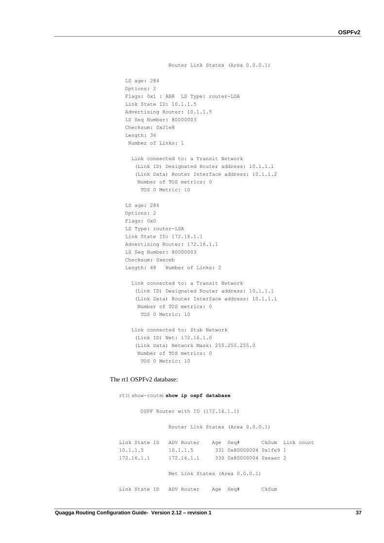
OSPFv2
Quagga Routing Configuration Guide- Version 2.12 – revision 1 37
Router Link States (Area 0.0.0.1)
LS age: 284
Options: 2
Flags: 0x1 : ABR LS Type: router-LSA
Link State ID: 10.1.1.5
Advertising Router: 10.1.1.5
LS Seq Number: 80000003
Checksum: 0x21e8
Length: 36
Number of Links: 1
Link connected to: a Transit Network
(Link ID) Designated Router address: 10.1.1.1
(Link Data) Router Interface address: 10.1.1.2
Number of TOS metrics: 0
TOS 0 Metric: 10
LS age: 284
Options: 2
Flags: 0x0
LS Type: router-LSA
Link State ID: 172.16.1.1
Advertising Router: 172.16.1.1
LS Seq Number: 80000003
Checksum: 0xeceb
Length: 48 Number of Links: 2
Link connected to: a Transit Network
(Link ID) Designated Router address: 10.1.1.1
(Link Data) Router Interface address: 10.1.1.1
Number of TOS metrics: 0
TOS 0 Metric: 10
Link connected to: Stub Network
(Link ID) Net: 172.16.1.0
(Link Data) Network Mask: 255.255.255.0
Number of TOS metrics: 0
TOS 0 Metric: 10
The rt1 OSPFv2 database:
rt1{show-route}show ip ospf database
OSPF Router with ID (172.16.1.1)
Router Link States (Area 0.0.0.1)
Link State ID ADV Router Age Seq# CkSum Link count
10.1.1.5 10.1.1.5 331 0x80000004 0x1fe9 1
172.16.1.1 172.16.1.1 330 0x80000004 0xeaec 2
Net Link States (Area 0.0.0.1)
Link State ID ADV Router Age Seq# CkSum
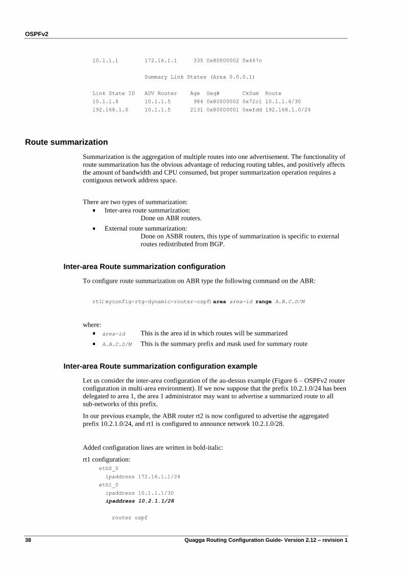
OSPFv2
38 Quagga Routing Configuration Guide- Version 2.12 – revision 1
10.1.1.1 172.16.1.1 335 0x80000002 0x447c
Summary Link States (Area 0.0.0.1)
Link State ID ADV Router Age Seq# CkSum Route
10.1.1.4 10.1.1.5 984 0x80000002 0x72c1 10.1.1.4/30
192.168.1.0 10.1.1.5 2131 0x80000001 0xefdd 192.168.1.0/24
Route summarization
Summarization is the aggregation of multiple routes into one advertisement. The functionality of
route summarization has the obvious advantage of reducing routing tables, and positively affects
the amount of bandwidth and CPU consumed, but proper summarization operation requires a
contiguous network address space.
There are two types of summarization:
Inter-area route summarization:
Done on ABR routers.
External route summarization:
Done on ASBR routers, this type of summarization is specific to external
routes redistributed from BGP.
Inter-area Route summarization configuration
To configure route summarization on ABR type the following command on the ABR:
rt1{myconfig-rtg-dynamic-router-ospf}area area-id range A.B.C.D/M
where:
area-id This is the area id in which routes will be summarized
A.B.C.D/M This is the summary prefix and mask used for summary route
Inter-area Route summarization configuration example
Let us consider the inter-area configuration of the au-dessus example (Figure 6 – OSPFv2 router
configuration in multi-area environment). If we now suppose that the prefix 10.2.1.0/24 has been
delegated to area 1, the area 1 administrator may want to advertise a summarized route to all
sub-networks of this prefix.
In our previous example, the ABR router rt2 is now configured to advertise the aggregated
prefix 10.2.1.0/24, and rt1 is configured to announce network 10.2.1.0/28.
Added configuration lines are written in bold-italic:
rt1 configuration:
eth0_0
ipaddress 172.16.1.1/24
eth1_0
ipaddress 10.1.1.1/30
ipaddress 10.2.1.1/28
router ospf
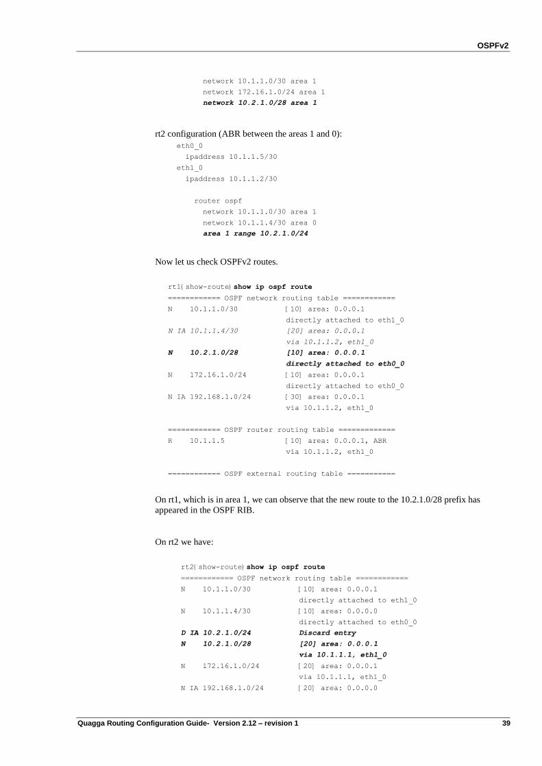
OSPFv2
Quagga Routing Configuration Guide- Version 2.12 – revision 1 39
network 10.1.1.0/30 area 1
network 172.16.1.0/24 area 1
network 10.2.1.0/28 area 1
rt2 configuration (ABR between the areas 1 and 0):
eth0_0
ipaddress 10.1.1.5/30
eth1_0
ipaddress 10.1.1.2/30
router ospf
network 10.1.1.0/30 area 1
network 10.1.1.4/30 area 0
area 1 range 10.2.1.0/24
Now let us check OSPFv2 routes.
rt1{show-route}show ip ospf route
============ OSPF network routing table ============
N 10.1.1.0/30 [10] area: 0.0.0.1
directly attached to eth1_0
N IA 10.1.1.4/30 [20] area: 0.0.0.1
via 10.1.1.2, eth1_0
N 10.2.1.0/28 [10] area: 0.0.0.1
directly attached to eth0_0
N 172.16.1.0/24 [10] area: 0.0.0.1
directly attached to eth0_0
N IA 192.168.1.0/24 [30] area: 0.0.0.1
via 10.1.1.2, eth1_0
============ OSPF router routing table =============
R 10.1.1.5 [10] area: 0.0.0.1, ABR
via 10.1.1.2, eth1_0
============ OSPF external routing table ===========
On rt1, which is in area 1, we can observe that the new route to the 10.2.1.0/28 prefix has
appeared in the OSPF RIB.
On rt2 we have:
rt2{show-route}show ip ospf route
============ OSPF network routing table ============
N 10.1.1.0/30 [10] area: 0.0.0.1
directly attached to eth1_0
N 10.1.1.4/30 [10] area: 0.0.0.0
directly attached to eth0_0
D IA 10.2.1.0/24 Discard entry
N 10.2.1.0/28 [20] area: 0.0.0.1
via 10.1.1.1, eth1_0
N 172.16.1.0/24 [20] area: 0.0.0.1
via 10.1.1.1, eth1_0
N IA 192.168.1.0/24 [20] area: 0.0.0.0
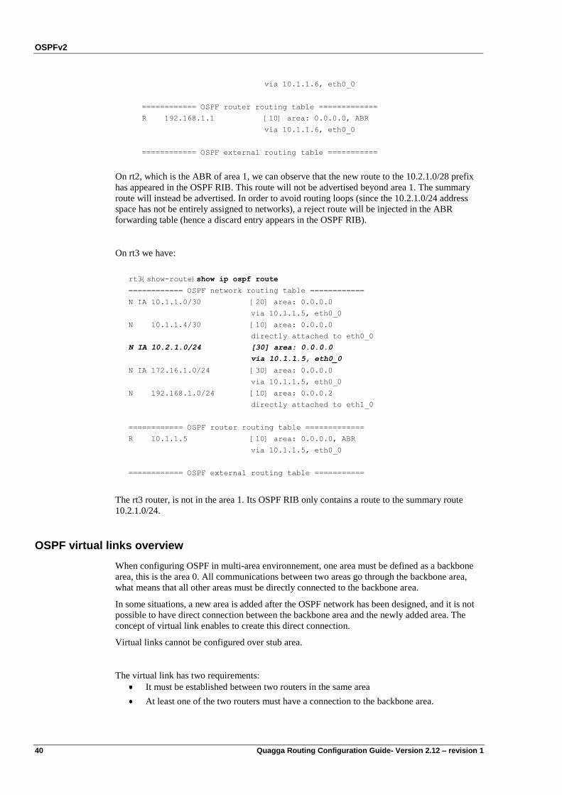
OSPFv2
40 Quagga Routing Configuration Guide- Version 2.12 – revision 1
via 10.1.1.6, eth0_0
============ OSPF router routing table =============
R 192.168.1.1 [10] area: 0.0.0.0, ABR
via 10.1.1.6, eth0_0
============ OSPF external routing table ===========
On rt2, which is the ABR of area 1, we can observe that the new route to the 10.2.1.0/28 prefix
has appeared in the OSPF RIB. This route will not be advertised beyond area 1. The summary
route will instead be advertised. In order to avoid routing loops (since the 10.2.1.0/24 address
space has not be entirely assigned to networks), a reject route will be injected in the ABR
forwarding table (hence a discard entry appears in the OSPF RIB).
On rt3 we have:
rt3{show-route}show ip ospf route
============ OSPF network routing table ============
N IA 10.1.1.0/30 [20] area: 0.0.0.0
via 10.1.1.5, eth0_0
N 10.1.1.4/30 [10] area: 0.0.0.0
directly attached to eth0_0
N IA 10.2.1.0/24 [30] area: 0.0.0.0
via 10.1.1.5, eth0_0
N IA 172.16.1.0/24 [30] area: 0.0.0.0
via 10.1.1.5, eth0_0
N 192.168.1.0/24 [10] area: 0.0.0.2
directly attached to eth1_0
============ OSPF router routing table =============
R 10.1.1.5 [10] area: 0.0.0.0, ABR
via 10.1.1.5, eth0_0
============ OSPF external routing table ===========
The rt3 router, is not in the area 1. Its OSPF RIB only contains a route to the summary route
10.2.1.0/24.
OSPF virtual links overview
When configuring OSPF in multi-area environnement, one area must be defined as a backbone
area, this is the area 0. All communications between two areas go through the backbone area,
what means that all other areas must be directly connected to the backbone area.
In some situations, a new area is added after the OSPF network has been designed, and it is not
possible to have direct connection between the backbone area and the newly added area. The
concept of virtual link enables to create this direct connection.
Virtual links cannot be configured over stub area.
The virtual link has two requirements:
It must be established between two routers in the same area
At least one of the two routers must have a connection to the backbone area.
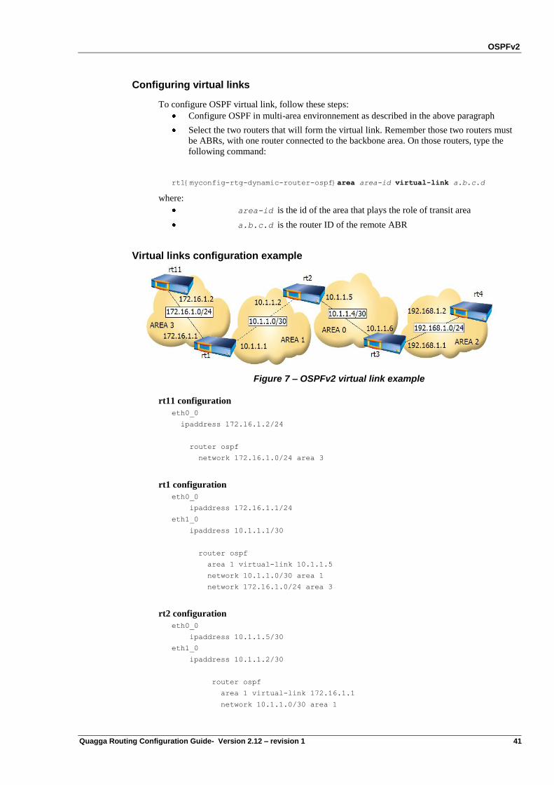
OSPFv2
Quagga Routing Configuration Guide- Version 2.12 – revision 1 41
Configuring virtual links
To configure OSPF virtual link, follow these steps:
Configure OSPF in multi-area environnement as described in the above paragraph
Select the two routers that will form the virtual link. Remember those two routers must
be ABRs, with one router connected to the backbone area. On those routers, type the
following command:
rt1{myconfig-rtg-dynamic-router-ospf}area area-id virtual-link a.b.c.d
where:
area-id is the id of the area that plays the role of transit area
a.b.c.d is the router ID of the remote ABR
Virtual links configuration example
Figure 7 – OSPFv2 virtual link example
rt11 configuration
eth0_0
ipaddress 172.16.1.2/24
router ospf
network 172.16.1.0/24 area 3
rt1 configuration
eth0_0
ipaddress 172.16.1.1/24
eth1_0
ipaddress 10.1.1.1/30
router ospf
area 1 virtual-link 10.1.1.5
network 10.1.1.0/30 area 1
network 172.16.1.0/24 area 3
rt2 configuration
eth0_0
ipaddress 10.1.1.5/30
eth1_0
ipaddress 10.1.1.2/30
router ospf
area 1 virtual-link 172.16.1.1
network 10.1.1.0/30 area 1
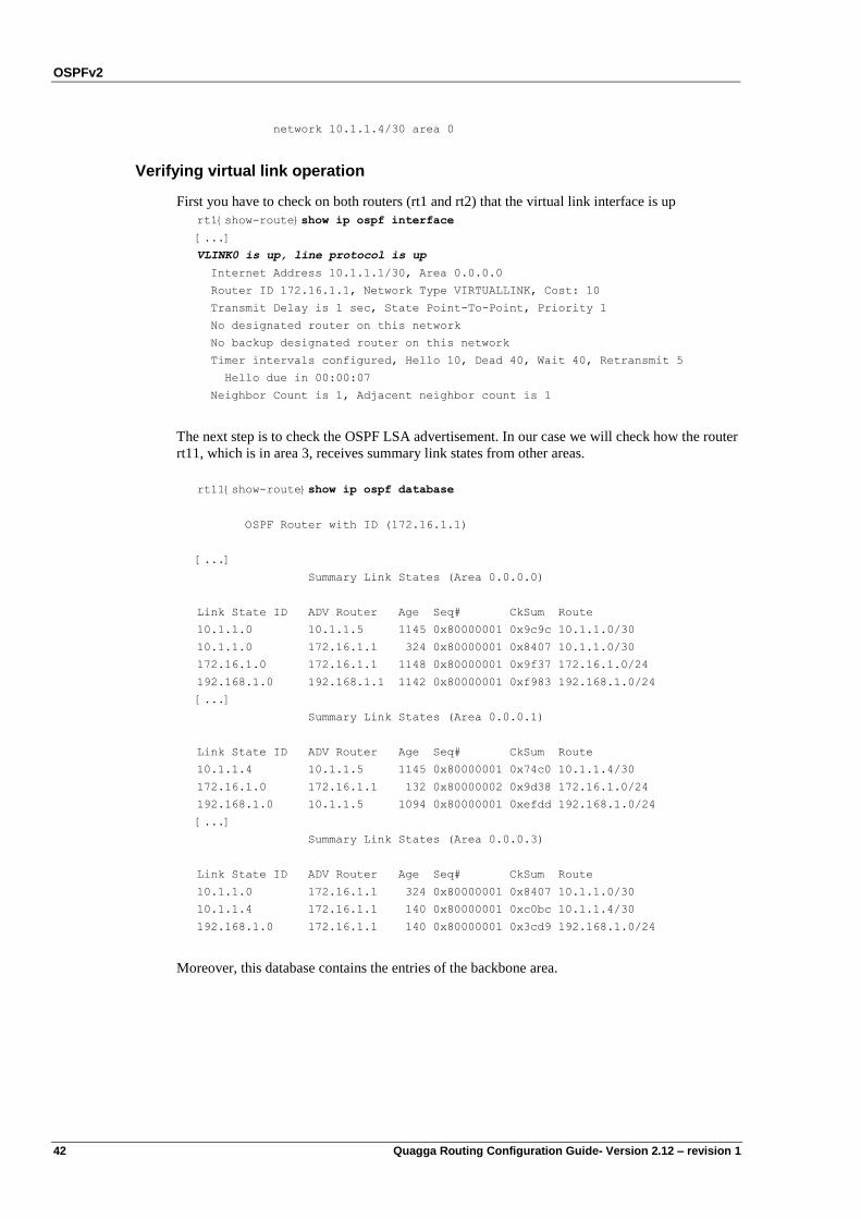
OSPFv2
42 Quagga Routing Configuration Guide- Version 2.12 – revision 1
network 10.1.1.4/30 area 0
Verifying virtual link operation
First you have to check on both routers (rt1 and rt2) that the virtual link interface is up
rt1{show-route}show ip ospf interface
[...]
VLINK0 is up, line protocol is up
Internet Address 10.1.1.1/30, Area 0.0.0.0
Router ID 172.16.1.1, Network Type VIRTUALLINK, Cost: 10
Transmit Delay is 1 sec, State Point-To-Point, Priority 1
No designated router on this network
No backup designated router on this network
Timer intervals configured, Hello 10, Dead 40, Wait 40, Retransmit 5
Hello due in 00:00:07
Neighbor Count is 1, Adjacent neighbor count is 1
The next step is to check the OSPF LSA advertisement. In our case we will check how the router
rt11, which is in area 3, receives summary link states from other areas.
rt11{show-route}show ip ospf database
OSPF Router with ID (172.16.1.1)
[...]
Summary Link States (Area 0.0.0.0)
Link State ID ADV Router Age Seq# CkSum Route
10.1.1.0 10.1.1.5 1145 0x80000001 0x9c9c 10.1.1.0/30
10.1.1.0 172.16.1.1 324 0x80000001 0x8407 10.1.1.0/30
172.16.1.0 172.16.1.1 1148 0x80000001 0x9f37 172.16.1.0/24
192.168.1.0 192.168.1.1 1142 0x80000001 0xf983 192.168.1.0/24
[...]
Summary Link States (Area 0.0.0.1)
Link State ID ADV Router Age Seq# CkSum Route
10.1.1.4 10.1.1.5 1145 0x80000001 0x74c0 10.1.1.4/30
172.16.1.0 172.16.1.1 132 0x80000002 0x9d38 172.16.1.0/24
192.168.1.0 10.1.1.5 1094 0x80000001 0xefdd 192.168.1.0/24
[...]
Summary Link States (Area 0.0.0.3)
Link State ID ADV Router Age Seq# CkSum Route
10.1.1.0 172.16.1.1 324 0x80000001 0x8407 10.1.1.0/30
10.1.1.4 172.16.1.1 140 0x80000001 0xc0bc 10.1.1.4/30
192.168.1.0 172.16.1.1 140 0x80000001 0x3cd9 192.168.1.0/24
Moreover, this database contains the entries of the backbone area.
OSPFv2
Quagga Routing Configuration Guide- Version 2.12 – revision 1 43
OSPF stub area overview
In some Autonomous Systems, the majority of the link-state database may consist of AS-
external-LSAs. An OSPF AS-external-LSA is usually flooded throughout the entire AS.
However, OSPF allows certain areas to be configured as "stub areas". AS-external-LSAs are not
flooded into/throughout stub areas; routing to AS external destinations in these areas is based on
a default route. This reduces the link-state database size, and therefore the memory
requirements, for a stub area's internal routers.
To configure a stub area, enter for example:
rt1{myconfig-rtg-dynamic-router-ospf}area area-id stub
where:
area-id is the id of the stub area
Totally stubby area overview
This feature prevents the ospf ABR from injecting inter-area summary into the considered area.
A Stub Area restricts the LSA types being injected into a stub area from other areas to Type 3
Summary LSA‟s. Type 4‟s and 5‟s are represented by a default route to the Area Border Router.
A totally stubby area takes this further by restricting Type 3‟s as well, so all traffic being
injected into a totally stubby area are represented by a default route.
To sum up, this means that the AS-external-LSAs (Type-5 LSA) and ASBR-Summary-LSA
(Type-4 LSA) and Network summary LSA (Type-3 LSA) are not flooded into a totally stub
areas.
For example:
rt1{myconfig-rtg-dynamic-router-ospf}area area-id stub no-summary
where:
area-id is the id of the stub area
OSPF NSSA overview
The Quagga software supports the OSPF NSSA (Not So Stubby Area). This concept was first
described in RFC 1587. An OSPF area is said to be NSSA if it can accept some external
autonomous system routes. These routes are said to be LSA type 7. An NSSA area is an OSPF
area extended to a remote site which does not run OSPFv2.
For example:
rt1{myconfig-rtg-dynamic-router-ospf}area area-id nssa [param]
where:
area-id is the id of the NSSA area
where param may be:
translate-always Configure NSSA-ABR to always translate
translate-candidate Configure NSSA-ABR for translate election
(default)
translate-never Configure NSSA-ABR to never translate
default-metric-type Set the type7-default metric-type of a nssa area
no-propagate Do not set P-bit in originated Type-7
LSAs
no-summary Do not inject inter-area routes into
nssa
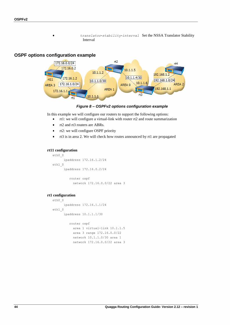
OSPFv2
44 Quagga Routing Configuration Guide- Version 2.12 – revision 1
translator-stability-interval Set the NSSA Translator Stability
Interval
OSPF options configuration example
Figure 8 – OSPFv2 options configuration example
In this example we will configure our routers to support the following options:
rt1: we will configure a virtual-link with router rt2 and route summarization
rt2 and rt3 routers are ABRs.
rt2: we will configure OSPF priority
rt3 is in area 2. We will check how routes announced by rt1 are propagated
rt11 configuration
eth0_0
ipaddress 172.16.1.2/24
eth1_0
ipaddress 172.16.0.2/24
router ospf
network 172.16.0.0/22 area 3
rt1 configuration
eth0_0
ipaddress 172.16.1.1/24
eth1_0
ipaddress 10.1.1.1/30
router ospf
area 1 virtual-link 10.1.1.5
area 3 range 172.16.0.0/22
network 10.1.1.0/30 area 1
network 172.16.0.0/22 area 3
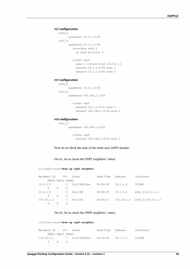
OSPFv2
Quagga Routing Configuration Guide- Version 2.12 – revision 1 45
rt2 configuration
eth0_0
ipaddress 10.1.1.5/30
eth1_0
ipaddress 10.1.1.2/30
interface eth1_0
ip ospf priority 3
router ospf
area 1 virtual-link 172.16.1.1
network 10.1.1.0/30 area 1
network 10.1.1.4/30 area 0
rt3 configuration
eth0_0
ipaddress 10.1.1.6/30
eth1_0
ipaddress 192.168.1.1/24
router ospf
network 10.1.1.4/30 area 0
network 192.168.1.0/24 area 2
rt4 configuration
eth1_0
ipaddress 192.168.1.2/24
router ospf
network 192.168.1.0/24 area 2
Now let us check the state of the multi-area OSPF domain.
On rt1, let us check the OSPF neighbors‟ status:
rt1{show-route}show ip ospf neighbor
Neighbor ID Pri State Dead Time Address Interface
RXmtL RqstL DBsmL
10.1.1.5 1 Full/DROther 00:00:34 10.1.1.2 VLINK0
0 0 0
10.1.1.5 3 Full/DR 00:00:35 10.1.1.2 eth1_0:10.1.1.1
0 0 0
172.16.1.2 1 Full/DR 00:00:31 172.16.1.2 eth0_0:172.16.1.1
0 0 0
On rt2, let us check the OSPF neighbors‟ status:
rt2{show-route}show ip ospf neighbor
Neighbor ID Pri State Dead Time Address Interface
RXmtL RqstL DBsmL
172.16.1.1 1 Full/DROther 00:00:39 10.1.1.1 VLINK0
0 0 0
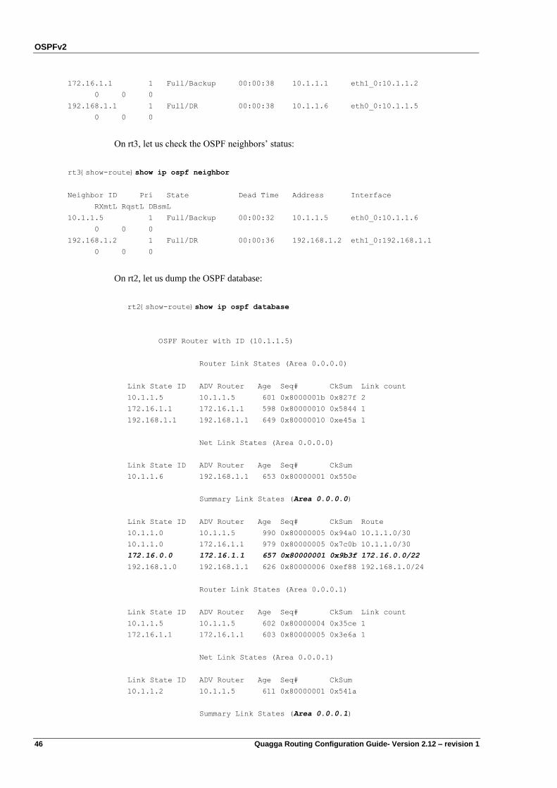
OSPFv2
46 Quagga Routing Configuration Guide- Version 2.12 – revision 1
172.16.1.1 1 Full/Backup 00:00:38 10.1.1.1 eth1_0:10.1.1.2
0 0 0
192.168.1.1 1 Full/DR 00:00:38 10.1.1.6 eth0_0:10.1.1.5
0 0 0
On rt3, let us check the OSPF neighbors‟ status:
rt3{show-route}show ip ospf neighbor
Neighbor ID Pri State Dead Time Address Interface
RXmtL RqstL DBsmL
10.1.1.5 1 Full/Backup 00:00:32 10.1.1.5 eth0_0:10.1.1.6
0 0 0
192.168.1.2 1 Full/DR 00:00:36 192.168.1.2 eth1_0:192.168.1.1
0 0 0
On rt2, let us dump the OSPF database:
rt2{show-route}show ip ospf database
OSPF Router with ID (10.1.1.5)
Router Link States (Area 0.0.0.0)
Link State ID ADV Router Age Seq# CkSum Link count
10.1.1.5 10.1.1.5 601 0x8000001b 0x827f 2
172.16.1.1 172.16.1.1 598 0x80000010 0x5844 1
192.168.1.1 192.168.1.1 649 0x80000010 0xe45a 1
Net Link States (Area 0.0.0.0)
Link State ID ADV Router Age Seq# CkSum
10.1.1.6 192.168.1.1 653 0x80000001 0x550e
Summary Link States (Area 0.0.0.0)
Link State ID ADV Router Age Seq# CkSum Route
10.1.1.0 10.1.1.5 990 0x80000005 0x94a0 10.1.1.0/30
10.1.1.0 172.16.1.1 979 0x80000005 0x7c0b 10.1.1.0/30
172.16.0.0 172.16.1.1 657 0x80000001 0x9b3f 172.16.0.0/22
192.168.1.0 192.168.1.1 626 0x80000006 0xef88 192.168.1.0/24
Router Link States (Area 0.0.0.1)
Link State ID ADV Router Age Seq# CkSum Link count
10.1.1.5 10.1.1.5 602 0x80000004 0x35ce 1
172.16.1.1 172.16.1.1 603 0x80000005 0x3e6a 1
Net Link States (Area 0.0.0.1)
Link State ID ADV Router Age Seq# CkSum
10.1.1.2 10.1.1.5 611 0x80000001 0x541a
Summary Link States (Area 0.0.0.1)
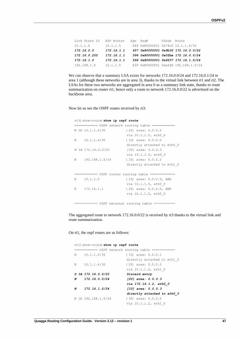
OSPFv2
Quagga Routing Configuration Guide- Version 2.12 – revision 1 47
Link State ID ADV Router Age Seq# CkSum Route
10.1.1.4 10.1.1.5 649 0x80000001 0x74c0 10.1.1.4/30
172.16.0.0 172.16.1.1 657 0x80000001 0x9b3f 172.16.0.0/22
172.16.0.255 172.16.1.1 596 0x80000001 0x0fbe 172.16.0.0/24
172.16.1.0 172.16.1.1 596 0x80000001 0x9f37 172.16.1.0/24
192.168.1.0 10.1.1.5 639 0x80000001 0xefdd 192.168.1.0/24
We can observe that a summary LSA exists for networks 172.16.0.0/24 and 172.16.0.1/24 in
area 1 (although these networks are in area 3), thanks to the virtual link between rt1 and rt2. The
LSAs for these two networks are aggregated in area 0 as a summary link state, thanks to route
summarization on router rt1, hence only a route to network 172.16.0.0/22 is advertised on the
backbone area.
Now let us see the OSPF routes received by rt3:
rt3{show-route}show ip ospf route
============ OSPF network routing table ============
N IA 10.1.1.0/30 [20] area: 0.0.0.0
via 10.1.1.5, eth0_0
N 10.1.1.4/30 [10] area: 0.0.0.0
directly attached to eth0_0
N IA 172.16.0.0/22 [30] area: 0.0.0.0
via 10.1.1.5, eth0_0
N 192.168.1.0/24 [10] area: 0.0.0.2
directly attached to eth1_0
============ OSPF router routing table =============
R 10.1.1.5 [10] area: 0.0.0.0, ABR
via 10.1.1.5, eth0_0
R 172.16.1.1 [20] area: 0.0.0.0, ABR
via 10.1.1.5, eth0_0
============ OSPF external routing table ===========
The aggregated route to network 172.16.0.0/22 is received by rt3 thanks to the virtual link and
route summarization.
On rt1, the ospf routes are as follows:
rt1{show-route}show ip ospf route
============ OSPF network routing table ============
N 10.1.1.0/30 [10] area: 0.0.0.1
directly attached to eth1_0
N 10.1.1.4/30 [20] area: 0.0.0.0
via 10.1.1.2, eth1_0
D IA 172.16.0.0/22 Discard entry
N 172.16.0.0/24 [20] area: 0.0.0.3
via 172.16.1.2, eth0_0
N 172.16.1.0/24 [10] area: 0.0.0.3
directly attached to eth0_0
N IA 192.168.1.0/24 [30] area: 0.0.0.0
via 10.1.1.2, eth1_0
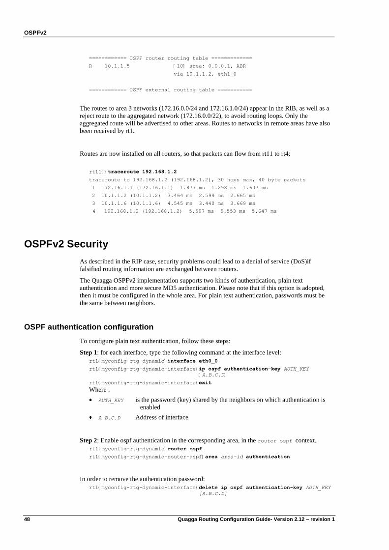
OSPFv2
48 Quagga Routing Configuration Guide- Version 2.12 – revision 1
============ OSPF router routing table =============
R 10.1.1.5 [10] area: 0.0.0.1, ABR
via 10.1.1.2, eth1_0
============ OSPF external routing table ===========
The routes to area 3 networks (172.16.0.0/24 and 172.16.1.0/24) appear in the RIB, as well as a
reject route to the aggregated network (172.16.0.0/22), to avoid routing loops. Only the
aggregated route will be advertised to other areas. Routes to networks in remote areas have also
been received by rt1.
Routes are now installed on all routers, so that packets can flow from rt11 to rt4:
rt11{}traceroute 192.168.1.2
traceroute to 192.168.1.2 (192.168.1.2), 30 hops max, 40 byte packets
1 172.16.1.1 (172.16.1.1) 1.877 ms 1.298 ms 1.607 ms
2 10.1.1.2 (10.1.1.2) 3.464 ms 2.599 ms 2.665 ms
3 10.1.1.6 (10.1.1.6) 4.545 ms 3.440 ms 3.669 ms
4 192.168.1.2 (192.168.1.2) 5.597 ms 5.553 ms 5.647 ms
OSPFv2 Security
As described in the RIP case, security problems could lead to a denial of service (DoS)if
falsified routing information are exchanged between routers.
The Quagga OSPFv2 implementation supports two kinds of authentication, plain text
authentication and more secure MD5 authentication. Please note that if this option is adopted,
then it must be configured in the whole area. For plain text authentication, passwords must be
the same between neighbors.
OSPF authentication configuration
To configure plain text authentication, follow these steps:
Step 1: for each interface, type the following command at the interface level:
rt1{myconfig-rtg-dynamic}interface eth0_0
rt1{myconfig-rtg-dynamic-interface}ip ospf authentication-key AUTH_KEY
[A.B.C.D]
rt1{myconfig-rtg-dynamic-interface}exit
Where :
AUTH_KEY is the password (key) shared by the neighbors on which authentication is
enabled
A.B.C.D Address of interface
Step 2: Enable ospf authentication in the corresponding area, in the router ospf context.
rt1{myconfig-rtg-dynamic}router ospf
rt1{myconfig-rtg-dynamic-router-ospf}area area-id authentication
In order to remove the authentication password:
rt1{myconfig-rtg-dynamic-interface}delete ip ospf authentication-key AUTH_KEY
[A.B.C.D]
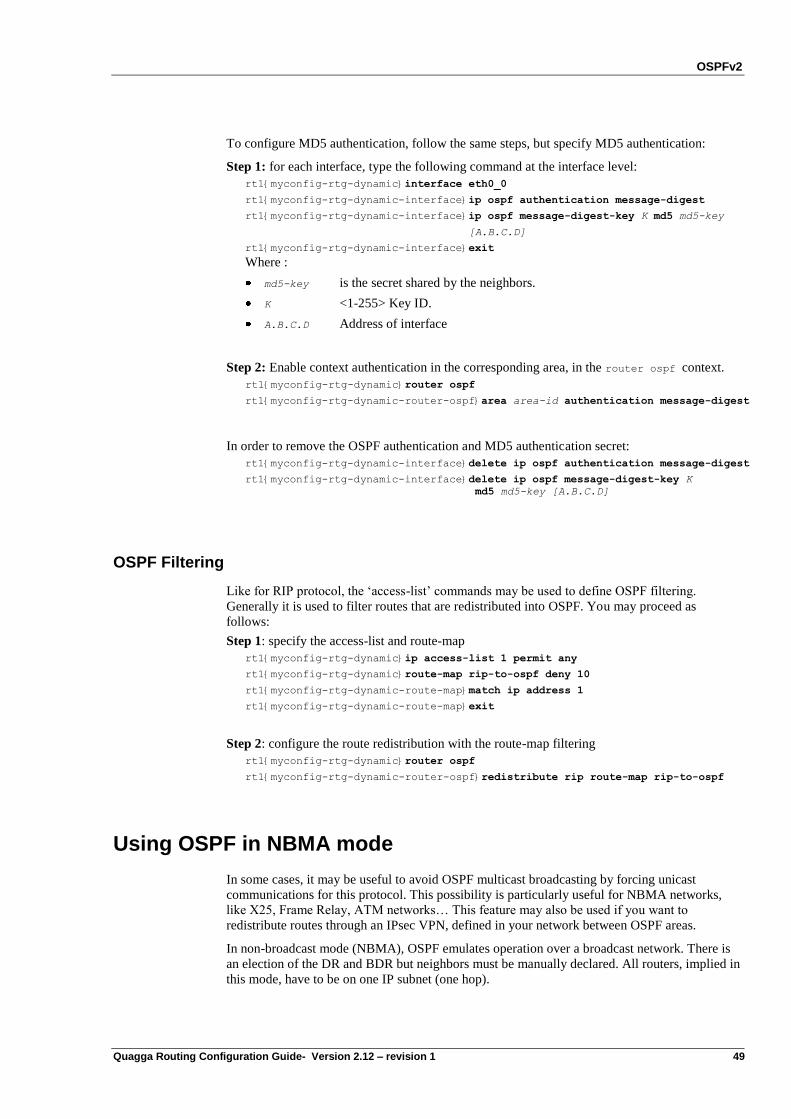
OSPFv2
Quagga Routing Configuration Guide- Version 2.12 – revision 1 49
To configure MD5 authentication, follow the same steps, but specify MD5 authentication:
Step 1: for each interface, type the following command at the interface level:
rt1{myconfig-rtg-dynamic}interface eth0_0
rt1{myconfig-rtg-dynamic-interface}ip ospf authentication message-digest
rt1{myconfig-rtg-dynamic-interface}ip ospf message-digest-key K md5 md5-key
[A.B.C.D]
rt1{myconfig-rtg-dynamic-interface}exit
Where :
md5-key is the secret shared by the neighbors.
K <1-255> Key ID.
A.B.C.D Address of interface
Step 2: Enable context authentication in the corresponding area, in the router ospf context.
rt1{myconfig-rtg-dynamic}router ospf
rt1{myconfig-rtg-dynamic-router-ospf}area area-id authentication message-digest
In order to remove the OSPF authentication and MD5 authentication secret:
rt1{myconfig-rtg-dynamic-interface}delete ip ospf authentication message-digest
rt1{myconfig-rtg-dynamic-interface}delete ip ospf message-digest-key K
md5 md5-key [A.B.C.D]
OSPF Filtering
Like for RIP protocol, the „access-list‟ commands may be used to define OSPF filtering.
Generally it is used to filter routes that are redistributed into OSPF. You may proceed as
follows:
Step 1: specify the access-list and route-map
rt1{myconfig-rtg-dynamic}ip access-list 1 permit any
rt1{myconfig-rtg-dynamic}route-map rip-to-ospf deny 10
rt1{myconfig-rtg-dynamic-route-map}match ip address 1
rt1{myconfig-rtg-dynamic-route-map}exit
Step 2: configure the route redistribution with the route-map filtering
rt1{myconfig-rtg-dynamic}router ospf
rt1{myconfig-rtg-dynamic-router-ospf}redistribute rip route-map rip-to-ospf
Using OSPF in NBMA mode
In some cases, it may be useful to avoid OSPF multicast broadcasting by forcing unicast
communications for this protocol. This possibility is particularly useful for NBMA networks,
like X25, Frame Relay, ATM networks… This feature may also be used if you want to
redistribute routes through an IPsec VPN, defined in your network between OSPF areas.
In non-broadcast mode (NBMA), OSPF emulates operation over a broadcast network. There is
an election of the DR and BDR but neighbors must be manually declared. All routers, implied in
this mode, have to be on one IP subnet (one hop).
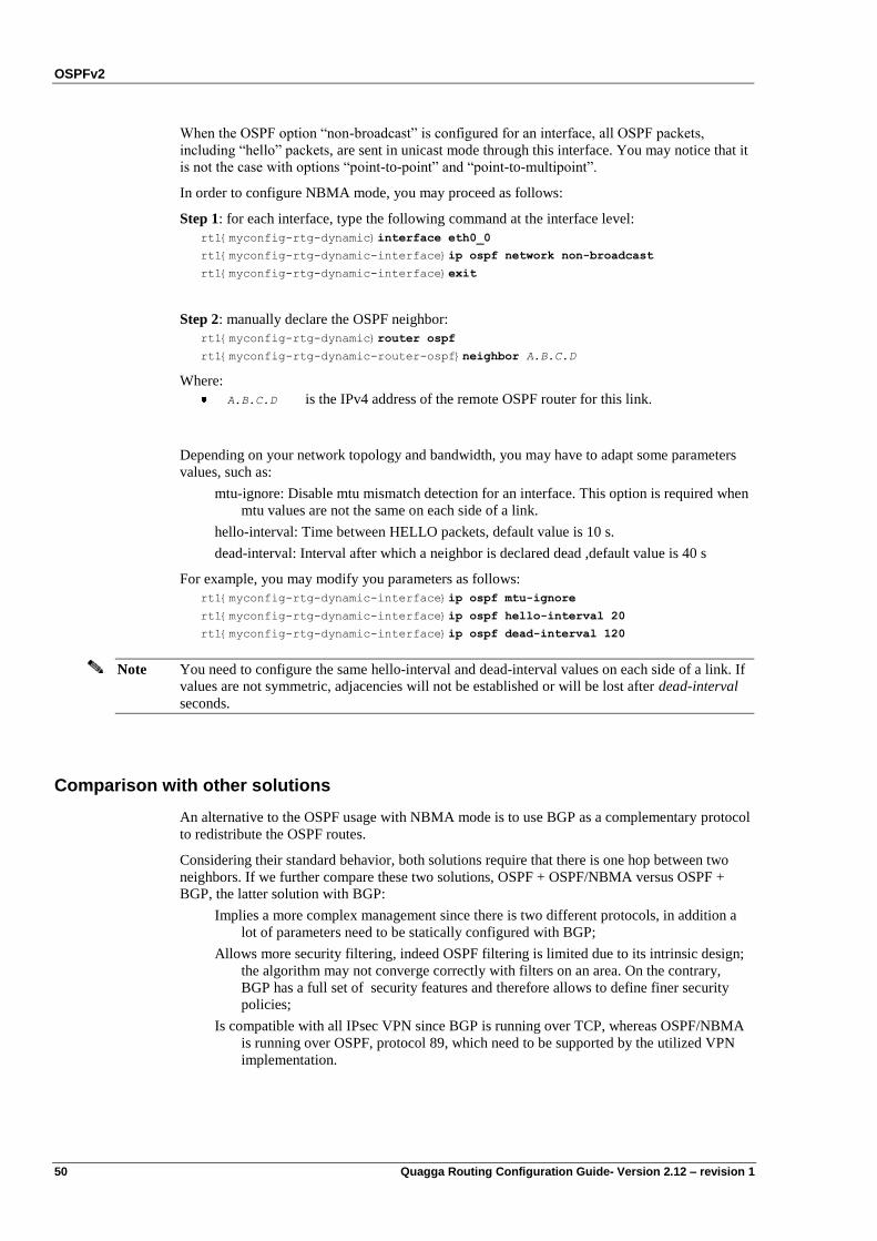
OSPFv2
50 Quagga Routing Configuration Guide- Version 2.12 – revision 1
When the OSPF option “non-broadcast” is configured for an interface, all OSPF packets,
including “hello” packets, are sent in unicast mode through this interface. You may notice that it
is not the case with options “point-to-point” and “point-to-multipoint”.
In order to configure NBMA mode, you may proceed as follows:
Step 1: for each interface, type the following command at the interface level:
rt1{myconfig-rtg-dynamic}interface eth0_0
rt1{myconfig-rtg-dynamic-interface}ip ospf network non-broadcast
rt1{myconfig-rtg-dynamic-interface}exit
Step 2: manually declare the OSPF neighbor:
rt1{myconfig-rtg-dynamic}router ospf
rt1{myconfig-rtg-dynamic-router-ospf}neighbor A.B.C.D
Where:
A.B.C.D is the IPv4 address of the remote OSPF router for this link.
Depending on your network topology and bandwidth, you may have to adapt some parameters
values, such as:
mtu-ignore: Disable mtu mismatch detection for an interface. This option is required when
mtu values are not the same on each side of a link.
hello-interval: Time between HELLO packets, default value is 10 s.
dead-interval: Interval after which a neighbor is declared dead ,default value is 40 s
For example, you may modify you parameters as follows:
rt1{myconfig-rtg-dynamic-interface}ip ospf mtu-ignore
rt1{myconfig-rtg-dynamic-interface}ip ospf hello-interval 20
rt1{myconfig-rtg-dynamic-interface}ip ospf dead-interval 120
Note You need to configure the same hello-interval and dead-interval values on each side of a link. If
values are not symmetric, adjacencies will not be established or will be lost after dead-interval
seconds.
Comparison with other solutions
An alternative to the OSPF usage with NBMA mode is to use BGP as a complementary protocol
to redistribute the OSPF routes.
Considering their standard behavior, both solutions require that there is one hop between two
neighbors. If we further compare these two solutions, OSPF + OSPF/NBMA versus OSPF +
BGP, the latter solution with BGP:
Implies a more complex management since there is two different protocols, in addition a
lot of parameters need to be statically configured with BGP;
Allows more security filtering, indeed OSPF filtering is limited due to its intrinsic design;
the algorithm may not converge correctly with filters on an area. On the contrary,
BGP has a full set of security features and therefore allows to define finer security
policies;
Is compatible with all IPsec VPN since BGP is running over TCP, whereas OSPF/NBMA
is running over OSPF, protocol 89, which need to be supported by the utilized VPN
implementation.
OSPFv2
Quagga Routing Configuration Guide- Version 2.12 – revision 1 51
You may notice that other technologies such as MPLS or IPIP tunnelling are generally used to
do the same over a backbone.
High Availability
It is sometimes useful for High Availability purpose to have redundancy between two routers. In
some cases, this redundancy MUST not be associated with load balancing, hence in case of
router swap; the routing convergence time must be addressed. This will be done, without any
modification to OSPF itself, but rather, with configuration tuning.
It is assumed that a mechanism, or at least an administrator, makes a choice in order to elect a
router as the “master”. The basic idea is:
Have all routers run OSPF simultaneously, with:
o Keeping the priority for DR/BDR election , unchanged
o Setting up adjacency with other routers, hence having a fully up-to-date
database
Elect a router on the link, that will be “master”, the others being the slaves
o On the Master, run OSPF normally
o On Slaves, run OSPF in “stub router” mode
With such a configuration, all the traffic will cross the master because the cost is the lower. In
case of failure on the master, the traffic is forwarded through the slave when it is the only
available path. It is possible to adopt a policy that makes a slave become the master, so that
when the old master is repaired and available again, the traffic path is not uselessly re-
forwarded:
When a router comes to Master state, revert to “normal” router mode,
When the old master is repaired, make it become slave in stub router mode.
The stub router behavior is described in RFC3137 “OSPF Stub Router Advertisement”. This
feature is not yet supported by Quagga, however it merely consists in setting interface costs to
infinity on all interfaces. Of course, if an interface is attached to a stub network accessible only
through this router‟s interface, the cost should not be set to infinity.
Step 1: On the Slave(s), be a stub router …
rt_slave{myconfig-rtg-dynamic}interface eth0_0
rt_slave{myconfig-rtg-dynamic-interface}ip ospf cost 65535
rt_slave{myconfig-rtg-dynamic-interface}exit
rt_slave{myconfig-rtg-dynamic}interface eth1_0
rt_slave{myconfig-rtg-dynamic-interface}ip ospf cost 65535
rt_slave{myconfig-rtg-dynamic-interface}exit
...
Step 2: On the (newly) Master, re-enable interface,
rt_master{myconfig}interface eth0
rt_master{myconfig-rtg-dynamic-interface}delete ip ospf cost
rt_master{myconfig-rtg-dynamic-interface}exit
rt_master{myconfig}interface eth1
rt_master{myconfig-rtg-dynamic-interface}delete ip ospf cost
rt_master{myconfig-rtg-dynamic-interface}exit

OSPFv2
52 Quagga Routing Configuration Guide- Version 2.12 – revision 1
In addition, if these master and slave(s) OSPF routers are at a border of the network, it is
necessary to add options that prevent other internal OSPF routers to use external routing
information from the slave.
Thus, on the Slave, add:
rt_slave {myconfig-rtg-dynamic}router ospf
rt_slave{myconfig-rtg-dynamic-router-ospf}delete default-information originate
rt_slave{myconfig-rtg-dynamic-router-ospf}delete redistribute PROTO [route-map
REDIST-ROUTE-MAP]
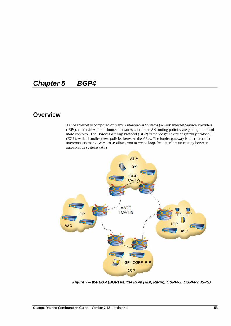
Quagga Routing Configuration Guide – Version 2.12 – revision 1 53
Chapter 5 BGP4
Overview
As the Internet is composed of many Autonomous Systems (ASes): Internet Service Providers
(ISPs), universities, multi-homed networks... the inter-AS routing policies are getting more and
more complex. The Border Gateway Protocol (BGP) is the today‟s exterior gateway protocol
(EGP), which handles these policies between the ASes. The border gateway is the router that
interconnects many ASes. BGP allows you to create loop-free interdomain routing between
autonomous systems (AS).
Figure 9 – the EGP (BGP) vs. the IGPs (RIP, RIPng, OSPFv2, OSPFv3, IS-IS)
BGP4
54 Quagga Routing Configuration Guide- Version 2.12 – revision 1
The Border Gateway Protocol (BGP) came up at the beginning of the 90‟s. The first RFC of
BGP was published in 1989. The today‟s BGP is referred to as BGP4, which was described by
the RFC 1771. It is an exterior routing protocol that distributes some network reachability
information. These network information are a set of network prefixes, which could be either
IPv4 or IPv6 network prefixes; and the reachability information are a list of AS numbers that are
crossed in order to reach some network prefixes.
BGP runs over the unicast Transport Control Protocol (TCP) on the well-known port 179. The
same TCP port is used for both IPv4 and IPv6.
Any two routers which have established a TCP connection to exchange BGP routing information
are called BGP peers or BGP neighbors. The two peers begin by exchanging their full BGP
table, then incremental updates are sent when the routing tables change.
When BGP is running between two routers belonging to different ASes it is called Exterior
BGP, sometimes referenced as eBGP. When the two routers belong to the same AS it is called
interior BGP, referenced as iBGP.
In routing protocols design rules, the BGP routing protocol is mainly used to exchange routing
information between different Autonomous Systems. Within the same autonomous system,
routing information is exchanged through an IGP routing protocol like RIP or OSPF.
The Quagga provides the following features:
RFC 1771: A Border Gateway Protocol 4 (BGP-4)
RFC 1977: BGP Communities Attribute
RFC 2545: Use of BGP-4 Multiprotocol Extensions for IPv6 Inter-Domain Routing
RFC 2796: BGP Route Reflection An alternative to full mesh iBGP
RFC 2858: Multiprotocol Extensions for BGP-4
RFC 3065: Autonomous System Confederations for BGP
Introduction
ASN – Autonomous System Number
An autonomous system is an administrative set of routers, depending on an administrative
authority. There are public or assigned autonomous systems, and private autonomous systems.
An autonomous systems is identified by a number called Autonomous System Number (ASN).
The public ASNs are any registered ASN values that are not private. This autonomous system
numbers are assigned by the IANA or by Local Registries as for IP addresses. The private ASNs
are AS Numbers that are reserved by the IANA for private use. It means that the private block
must not be advertised on the global Internet. There are 1024 private ASNs that can be used for
local administration. These numbers are 64512 through 65535. They are very useful in order to
provision a set of BGP confederation.
BGP4
Quagga Routing Configuration Guide- Version 2.12 – revision 1 55
Configuring BGP
The three steps required to configure BGP
Step 1: Start/Stop BGP
It can be enabled via the following commands :
...
rt1{}edit conf myconfig
rt1{myconfig}rtg
rt1{myconfig-rtg}dynamic
rt1{myconfig-rtg-dynamic}router bgp ASN
where:
ASN is the AS number of your local Autonomous System.
BGP is disabled with the following command:
rt1{myconfig-rtg-dynamic}delete router bgp ASN
Step 2: Connect to a remote BGP router
Within the dynamic BGP context, the BGP associations are configured with the following
command:
rt1{myconfig-rtg-dynamic-router-bgp}neighbor A.B.C.D remote-as ASN
Where:
A.B.C.D is the IPv4 address of the remote BGP router
ASN is the AS number of the remote BGP router
Note The remote BGP router should be a direct next hop of your local BGP router. Otherwise you are
trying to configure a multihop BGP peering.
Step 3: Announce the prefixes
Within the dynamic BGP context, the network prefixes, which will be originated from your AS,
can be configured with the following command:
rt1{myconfig-rtg-dynamic-router-bgp}network A.B.C.D/M
Where:
A.B.C.D is the IPv4 prefix that will be announced by your BGP router
M is the length of the mask of the A.B.C.D network
Note The network prefix A.B.C.D/M should be an aggregated (summarized) prefix of the networks
that you own and that you originate.
Moreover, in order to avoid a routing loop, a black-hole route or a reject route should be
configured.
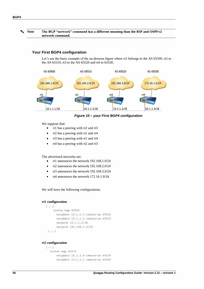
BGP4
56 Quagga Routing Configuration Guide- Version 2.12 – revision 1
Note The BGP “network” command has a different meaning than the RIP and OSPFv2
network command.
Your First BGP4 configuration
Let‟s use the basic example of the au-dessous figure where rt1 belongs to the AS 65500, rt2 to
the AS 65510, rt3 to the AS 65520 and rt4 to 65530.
Figure 10 – your First BGP4 configuration
We suppose that:
rt1 has a peering with rt2 and rt3
rt2 has a peering with rt1 and rt4
rt3 has a peering with rt1 and rt4
rt4 has a peering with rt2 and rt3
The advertised networks are:
rt1 announces the network 192.168.1.0/24
rt2 announces the network 192.168.2.0/24
rt3 announces the network 192.168.3.0/24
rt4 announces the network 172.16.1.0/24
We will have the following configurations.
rt1 configuration
[...]
router bgp 65500
neighbor 10.1.1.3 remote-as 65520
neighbor 10.1.1.2 remote-as 65510
network 10.1.1.0/28
network 192.168.1.0/24
[...]
rt2 configuration
[...]
router bgp 65510
neighbor 10.1.1.4 remote-as 65530
neighbor 10.1.1.1 remote-as 65500
BGP4
Quagga Routing Configuration Guide- Version 2.12 – revision 1 57
network 10.1.1.0/28
network 192.168.2.0/24
[...]
rt3 configuration
[...]
router bgp 65520
neighbor 10.1.1.4 remote-as 65530
neighbor 10.1.1.1 remote-as 65500
network 10.1.1.0/28
network 192.168.3.0/24
[...]
rt4 configuration
[...]
router bgp 65530
neighbor 10.1.1.3 remote-as 65520
neighbor 10.1.1.2 remote-as 65510
network 10.1.1.0/28
network 172.16.1.0/24
[...]
To check the status of the BGP connection, type the command show ip bgp summary. This is
the first thing to do to check whether the BGP session is ok.
rt1{show-route}show ip bgp summary
BGP router identifier 192.168.1.1, local AS number 65500
11 BGP AS-PATH entries
0 BGP community entries
Neighbor V AS MsgRcvd MsgSent TblVer InQ OutQ Up/Down State/PfxRcd
10.1.1.2 4 65510 35 35 0 0 0 00:26:10 4
10.1.1.3 4 65520 22 21 0 0 0 00:15:33 4
Total number of neighbors 2
Please check the output of the “state” column, it must be blank in case the BGP connection is
established, otherwise it reflects the state of the BGP connection. The different BGP session
states are studied later in the section.
This command is very helpful and gives a summary of the different BGP sessions.
From the output we can conclude that the router rt1 has two BGP neighbors, one in AS 65510
the other in AS 65520, and that rt1 is receiving 4 prefixes from each neighbor (PfxRcd).
For more information about a given session, use the detailed command show ip bgp neighbors
A.B.C.D.
This command gives detailed BGP information about a given neighbor
rt1{show-route}show ip bgp neighbors 10.1.1.3
BGP neighbor is 10.1.1.3, remote AS 65520, local AS 65500, external link
BGP4
58 Quagga Routing Configuration Guide- Version 2.12 – revision 1
BGP version 4, remote router ID 192.168.3.1
BGP state = Established, up for 00:28:54
Last read 00:00:54, hold time is 180, keepalive interval is 60 seconds
Neighbor capabilities:
Route refresh: advertised and received (old and new)
Address family IPv4 Unicast: advertised and received
Received 35 messages, 0 notifications, 0 in queue
Sent 34 messages, 0 notifications, 0 in queue
Route refresh request: received 0, sent 0
Minimum time between advertisement runs is 30 seconds
For address family: IPv4 Unicast
Community attribute sent to this neighbor (both)
4 accepted prefixes
Connections established 1; dropped 0
Local host: 10.1.1.1, Local port: 3902
Foreign host: 10.1.1.3, Foreign port: 179
Nexthop: 10.1.1.1
Nexthop global: ::
Nexthop local: ::
BGP connection: shared network
Read thread: on Write thread: off
Please check that BGP state is ESTABLISHED (marked in bold in the previous output).
BGP4 configuration options
The BGP routing protocol is very rich and offers many options. In this paragraph we will study
the most used and useful BGP options.
We describe these options in the IPv4 context, however they are not specific to an address
family, and most of them are available with IPv6 too.
Aggregation
The main goal of aggregation is to summarize the number of network prefixes that are
announced into the Internet. In fact, aggregation is a requirement when the mask length is
greater to 24 because your peers or the peers of your peers will filter some of them.
However, the route aggregation can introduce some network loops or some black holes when it
is not set properly.
Please note that a BGP router can advertise an aggregated network only if one route of the
aggregate network is in the BGP table. For example if we consider four networks 192.168.0.0/24
through 192.168.3.0/24, the BGP router can advertise the aggregate network 192.168.0.0/22
only if at least one network (192.168.1.0/24 through 192.168.3.0/24) is in the BGP table.
(Otherwise we can see one of this network when typing the command show ip bgp).
Note also that if all the sub-networks of an aggregated network go down, this aggregated
network will not be advertised.
It is also recommended to check that the aggregated network is not stopped by an access list.
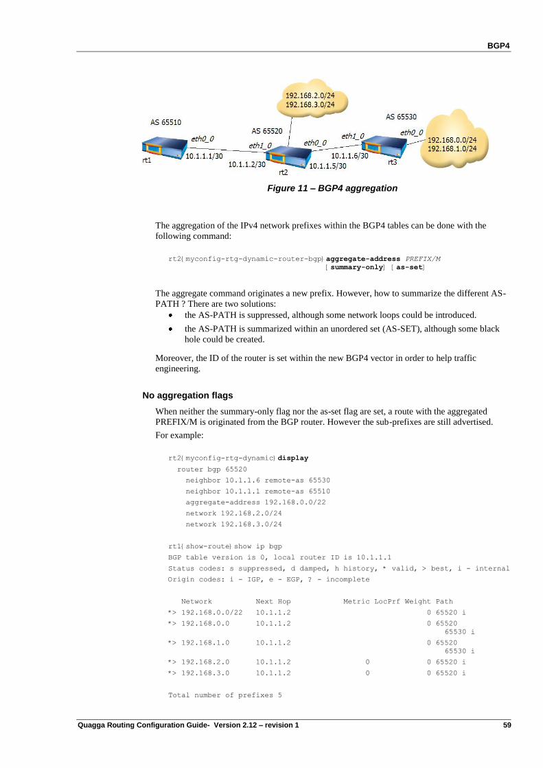
BGP4
Quagga Routing Configuration Guide- Version 2.12 – revision 1 59
Figure 11 – BGP4 aggregation
The aggregation of the IPv4 network prefixes within the BGP4 tables can be done with the
following command:
rt2{myconfig-rtg-dynamic-router-bgp}aggregate-address PREFIX/M
[summary-only] [as-set]
The aggregate command originates a new prefix. However, how to summarize the different AS-
PATH ? There are two solutions:
the AS-PATH is suppressed, although some network loops could be introduced.
the AS-PATH is summarized within an unordered set (AS-SET), although some black
hole could be created.
Moreover, the ID of the router is set within the new BGP4 vector in order to help traffic
engineering.
No aggregation flags
When neither the summary-only flag nor the as-set flag are set, a route with the aggregated
PREFIX/M is originated from the BGP router. However the sub-prefixes are still advertised.
For example:
rt2{myconfig-rtg-dynamic}display
router bgp 65520
neighbor 10.1.1.6 remote-as 65530
neighbor 10.1.1.1 remote-as 65510
aggregate-address 192.168.0.0/22
network 192.168.2.0/24
network 192.168.3.0/24
rt1{show-route}show ip bgp
BGP table version is 0, local router ID is 10.1.1.1
Status codes: s suppressed, d damped, h history, * valid, > best, i - internal
Origin codes: i - IGP, e - EGP, ? - incomplete
Network Next Hop Metric LocPrf Weight Path
*> 192.168.0.0/22 10.1.1.2 0 65520 i
*> 192.168.0.0 10.1.1.2 0 65520
65530 i
*> 192.168.1.0 10.1.1.2 0 65520
65530 i
*> 192.168.2.0 10.1.1.2 0 0 65520 i
*> 192.168.3.0 10.1.1.2 0 0 65520 i
Total number of prefixes 5
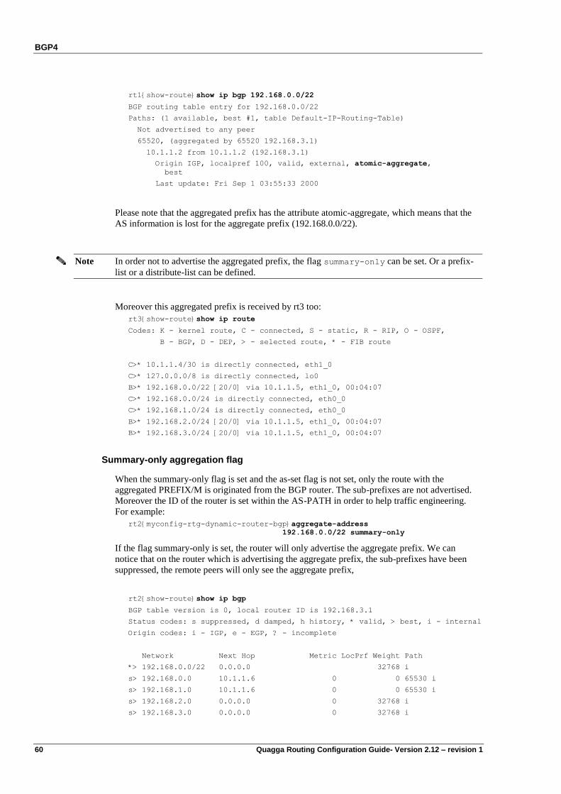
BGP4
60 Quagga Routing Configuration Guide- Version 2.12 – revision 1
rt1{show-route}show ip bgp 192.168.0.0/22
BGP routing table entry for 192.168.0.0/22
Paths: (1 available, best #1, table Default-IP-Routing-Table)
Not advertised to any peer
65520, (aggregated by 65520 192.168.3.1)
10.1.1.2 from 10.1.1.2 (192.168.3.1)
Origin IGP, localpref 100, valid, external, atomic-aggregate,
best
Last update: Fri Sep 1 03:55:33 2000
Please note that the aggregated prefix has the attribute atomic-aggregate, which means that the
AS information is lost for the aggregate prefix (192.168.0.0/22).
Note In order not to advertise the aggregated prefix, the flag summary-only can be set. Or a prefix-
list or a distribute-list can be defined.
Moreover this aggregated prefix is received by rt3 too:
rt3{show-route}show ip route
Codes: K - kernel route, C - connected, S - static, R - RIP, O - OSPF,
B - BGP, D - DEP, > - selected route, * - FIB route
C>* 10.1.1.4/30 is directly connected, eth1_0
C>* 127.0.0.0/8 is directly connected, lo0
B>* 192.168.0.0/22 [20/0] via 10.1.1.5, eth1_0, 00:04:07
C>* 192.168.0.0/24 is directly connected, eth0_0
C>* 192.168.1.0/24 is directly connected, eth0_0
B>* 192.168.2.0/24 [20/0] via 10.1.1.5, eth1_0, 00:04:07
B>* 192.168.3.0/24 [20/0] via 10.1.1.5, eth1_0, 00:04:07
Summary-only aggregation flag
When the summary-only flag is set and the as-set flag is not set, only the route with the
aggregated PREFIX/M is originated from the BGP router. The sub-prefixes are not advertised.
Moreover the ID of the router is set within the AS-PATH in order to help traffic engineering.
For example:
rt2{myconfig-rtg-dynamic-router-bgp}aggregate-address
192.168.0.0/22 summary-only
If the flag summary-only is set, the router will only advertise the aggregate prefix. We can
notice that on the router which is advertising the aggregate prefix, the sub-prefixes have been
suppressed, the remote peers will only see the aggregate prefix,
rt2{show-route}show ip bgp
BGP table version is 0, local router ID is 192.168.3.1
Status codes: s suppressed, d damped, h history, * valid, > best, i - internal
Origin codes: i - IGP, e - EGP, ? - incomplete
Network Next Hop Metric LocPrf Weight Path
*> 192.168.0.0/22 0.0.0.0 32768 i
s> 192.168.0.0 10.1.1.6 0 0 65530 i
s> 192.168.1.0 10.1.1.6 0 0 65530 i
s> 192.168.2.0 0.0.0.0 0 32768 i
s> 192.168.3.0 0.0.0.0 0 32768 i

BGP4
Quagga Routing Configuration Guide- Version 2.12 – revision 1 61
Total number of prefixes 5
The sub-prefixes which have been suppressed are labeled „s‟.
On the remote peer, only the route to 192.168.0.0/22 is received by the BGP RIB:
rt1{show-route}show ip bgp
BGP table version is 0, local router ID is 10.1.1.1
Status codes: s suppressed, d damped, h history, * valid, > best, i - internal
Origin codes: i - IGP, e - EGP, ? - incomplete
Network Next Hop Metric LocPrf Weight Path
*> 192.168.0.0/22 10.1.1.2 0 65520 i
Total number of prefixes 1
However, rt3 is still getting the aggregated route:
rt3{show-route}show ip bgp
BGP table version is 0, local router ID is 192.168.1.1
Status codes: s suppressed, d damped, h history, * valid, > best, i - internal
Origin codes: i - IGP, e - EGP, ? - incomplete
Network Next Hop Metric LocPrf Weight Path
*> 192.168.0.0/22 10.1.1.5 0 65520 i
*> 192.168.0.0 0.0.0.0 0 32768 i
*> 192.168.1.0 0.0.0.0 0 32768 i
Total number of prefixes 3
As-set aggregation flag
When the summary-only flag is not set and the as-set flag is set, a route with the aggregated
PREFIX/M is originated from the BGP router. Moreover the information of the previous AS-
PATHs is collected into an unordered list called an AS-SET. This AS-SET, that is included
within the new AS-PATH originated by the router, can help to avoid some networks loops.
However the sub-prefixes are still advertised.
rt4{myconfig-rtg-dynamic-router-bgp}aggregate-address 192.168.0.0/22 as-set
The AS information appears between brackets „{‟ „}‟. It is an unordered list of the Autonomous
Systems.
In our example we will have:
rt2{}show running-config
router bgp 65520
neighbor 10.1.1.6 remote-as 65530
neighbor 10.1.1.1 remote-as 65510
aggregate-address 192.168.0.0/22 as-set
network 192.168.2.0/24
network 192.168.3.0/24
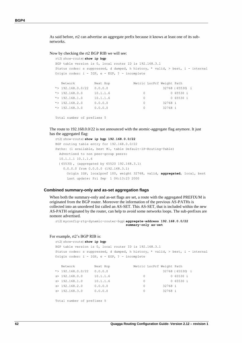
BGP4
62 Quagga Routing Configuration Guide- Version 2.12 – revision 1
As said before, rt2 can advertise an aggregate prefix because it knows at least one of its sub-
networks.
Now by checking the rt2 BGP RIB we will see:
rt2{show-route}show ip bgp
BGP table version is 0, local router ID is 192.168.3.1
Status codes: s suppressed, d damped, h history, * valid, > best, i - internal
Origin codes: i - IGP, e - EGP, ? - incomplete
Network Next Hop Metric LocPrf Weight Path
*> 192.168.0.0/22 0.0.0.0 32768 {65530} i
*> 192.168.0.0 10.1.1.6 0 0 65530 i
*> 192.168.1.0 10.1.1.6 0 0 65530 i
*> 192.168.2.0 0.0.0.0 0 32768 i
*> 192.168.3.0 0.0.0.0 0 32768 i
Total number of prefixes 5
The route to 192.168.0.0/22 is not announced with the atomic-aggregate flag anymore. It just
has the aggregated flag:
rt2{show-route}show ip bgp 192.168.0.0/22
BGP routing table entry for 192.168.0.0/22
Paths: (1 available, best #1, table Default-IP-Routing-Table)
Advertised to non peer-group peers:
10.1.1.1 10.1.1.6
{65530}, (aggregated by 65520 192.168.3.1)
0.0.0.0 from 0.0.0.0 (192.168.3.1)
Origin IGP, localpref 100, weight 32768, valid, aggregated, local, best
Last update: Fri Sep 1 04:13:23 2000
Combined summary-only and as-set aggregation flags
When both the summary-only and as-set flags are set, a route with the aggregated PREFIX/M is
originated from the BGP router. Moreover the information of the previous AS-PATHs is
collected into an unordered list called an AS-SET. This AS-SET, that is included within the new
AS-PATH originated by the router, can help to avoid some networks loops. The sub-prefixes are
nomore advertised.
rt2{myconfig-rtg-dynamic-router-bgp}aggregate-address 192.168.0.0/22
summary-only as-set
For example, rt2‟s BGP RIB is:
rt2{show-route}show ip bgp
BGP table version is 0, local router ID is 192.168.3.1
Status codes: s suppressed, d damped, h history, * valid, > best, i - internal
Origin codes: i - IGP, e - EGP, ? - incomplete
Network Next Hop Metric LocPrf Weight Path
*> 192.168.0.0/22 0.0.0.0 32768 {65530} i
s> 192.168.0.0 10.1.1.6 0 0 65530 i
s> 192.168.1.0 10.1.1.6 0 0 65530 i
s> 192.168.2.0 0.0.0.0 0 32768 i
s> 192.168.3.0 0.0.0.0 0 32768 i
Total number of prefixes 5
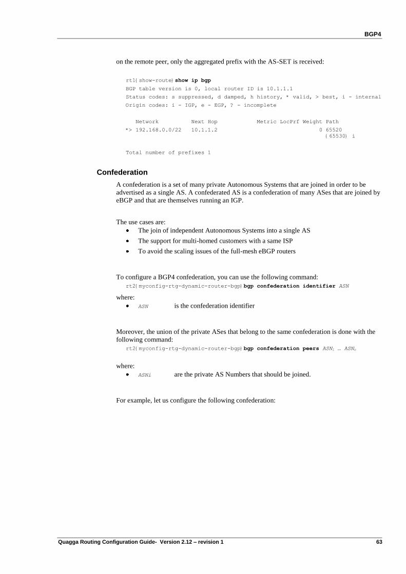
BGP4
Quagga Routing Configuration Guide- Version 2.12 – revision 1 63
on the remote peer, only the aggregated prefix with the AS-SET is received:
rt1{show-route}show ip bgp
BGP table version is 0, local router ID is 10.1.1.1
Status codes: s suppressed, d damped, h history, * valid, > best, i - internal
Origin codes: i - IGP, e - EGP, ? - incomplete
Network Next Hop Metric LocPrf Weight Path
*> 192.168.0.0/22 10.1.1.2 0 65520
{65530} i
Total number of prefixes 1
Confederation
A confederation is a set of many private Autonomous Systems that are joined in order to be
advertised as a single AS. A confederated AS is a confederation of many ASes that are joined by
eBGP and that are themselves running an IGP.
The use cases are:
The join of independent Autonomous Systems into a single AS
The support for multi-homed customers with a same ISP
To avoid the scaling issues of the full-mesh eBGP routers
To configure a BGP4 confederation, you can use the following command:
rt2{myconfig-rtg-dynamic-router-bgp}bgp confederation identifier ASN
where:
ASN is the confederation identifier
Moreover, the union of the private ASes that belong to the same confederation is done with the
following command:
rt2{myconfig-rtg-dynamic-router-bgp}bgp confederation peers ASN1 … ASNn
where:
ASNi are the private AS Numbers that should be joined.
For example, let us configure the following confederation:
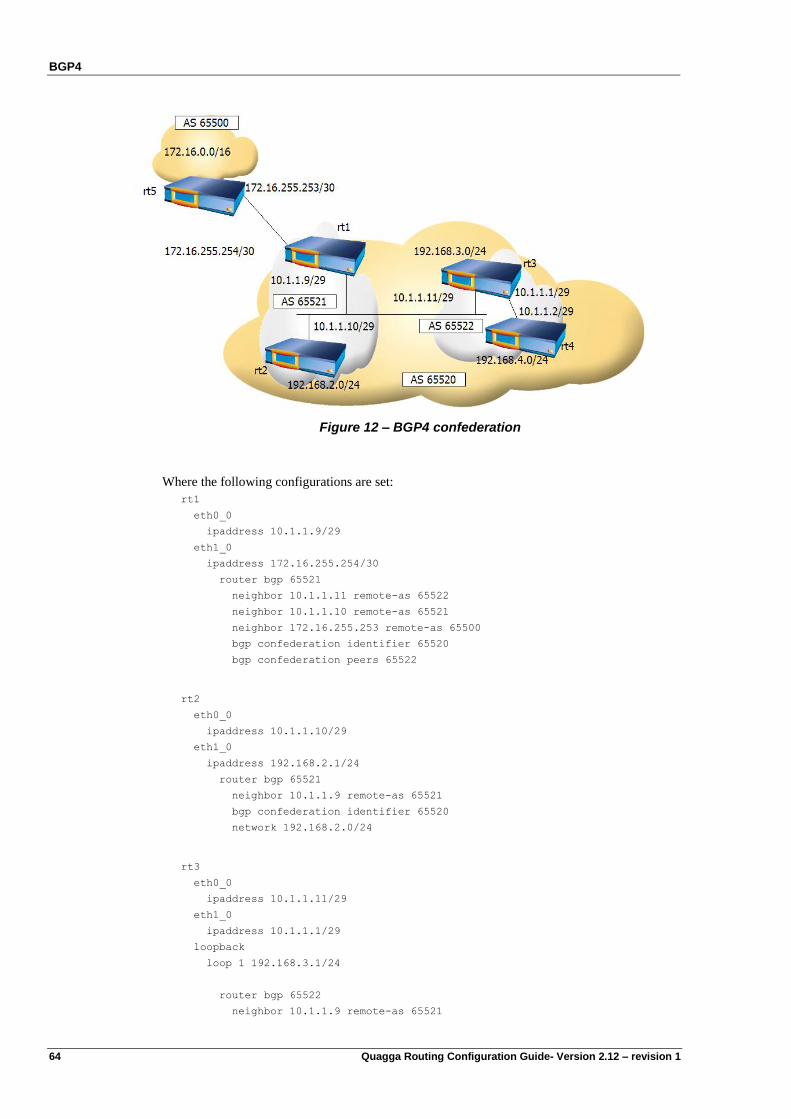
BGP4
64 Quagga Routing Configuration Guide- Version 2.12 – revision 1
Figure 12 – BGP4 confederation
Where the following configurations are set:
rt1
eth0_0
ipaddress 10.1.1.9/29
eth1_0
ipaddress 172.16.255.254/30
router bgp 65521
neighbor 10.1.1.11 remote-as 65522
neighbor 10.1.1.10 remote-as 65521
neighbor 172.16.255.253 remote-as 65500
bgp confederation identifier 65520
bgp confederation peers 65522
rt2
eth0_0
ipaddress 10.1.1.10/29
eth1_0
ipaddress 192.168.2.1/24
router bgp 65521
neighbor 10.1.1.9 remote-as 65521
bgp confederation identifier 65520
network 192.168.2.0/24
rt3
eth0_0
ipaddress 10.1.1.11/29
eth1_0
ipaddress 10.1.1.1/29
loopback
loop 1 192.168.3.1/24
router bgp 65522
neighbor 10.1.1.9 remote-as 65521
BGP4
Quagga Routing Configuration Guide- Version 2.12 – revision 1 65
neighbor 10.1.1.2 remote-as 65522
bgp confederation identifier 65520
bgp confederation peers 65521
network 192.168.3.0/24
rt4
eth0_0
ipaddress 192.168.4.1/24
eth1_0
ipaddress 10.1.1.2/29
router bgp 65522
neighbor 10.1.1.1 remote-as 65522
bgp confederation identifier 65520
network 192.168.4.1/24
However, when rt5 peers with rt1, it peers to the AS 65520 that is rt1‟s BGP confederation
identifier. It does not peer to the AS 65521 that is internal to the AS 65520:
rt5
eth0_0
ipaddress 172.16.0.1/16
eth1_0
ipaddress 172.16.255.253/30
router bgp 65500
neighbor 172.16.255.254 remote-as 65520
network 172.16.0.0/16
You can check this configuration on rt3 that displays the confederation path between
parenthesis:
rt3{show-route}show ip bgp
BGP table version is 0, local router ID is 192.168.3.1
Status codes: s suppressed, d damped, h history, * valid, > best, i - internal
Origin codes: i - IGP, e - EGP, ? - incomplete
Network Next Hop Metric LocPrf Weight Path
* 172.16.0.0 172.16.255.253 0 100 0 (65521)
65500 i
*> 192.168.2.0 10.1.1.10 0 100 0 (65521) i
*> 192.168.3.0 0.0.0.0 0 32768 i
*>i192.168.4.0 10.1.1.2 0 100 0 i
Total number of prefixes 4
rt3{show-route}show ip bgp 172.16.0.0
BGP routing table entry for 172.16.0.0/16
Paths: (1 available, no best path)
Not advertised to any peer
(65521) 65500
172.16.255.253 (inaccessible) from 10.1.1.9 (172.16.255.254)
Origin IGP, metric 0, localpref 100, valid, confed-external
Last update: Sat Sep 2 17:53:57 2000
Whereas the FIB of rt3 is:
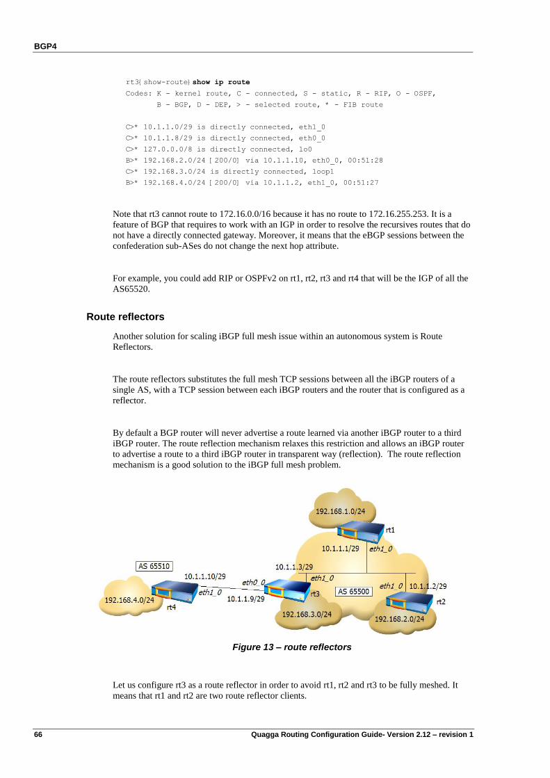
BGP4
66 Quagga Routing Configuration Guide- Version 2.12 – revision 1
rt3{show-route}show ip route
Codes: K - kernel route, C - connected, S - static, R - RIP, O - OSPF,
B - BGP, D - DEP, > - selected route, * - FIB route
C>* 10.1.1.0/29 is directly connected, eth1_0
C>* 10.1.1.8/29 is directly connected, eth0_0
C>* 127.0.0.0/8 is directly connected, lo0
B>* 192.168.2.0/24 [200/0] via 10.1.1.10, eth0_0, 00:51:28
C>* 192.168.3.0/24 is directly connected, loop1
B>* 192.168.4.0/24 [200/0] via 10.1.1.2, eth1_0, 00:51:27
Note that rt3 cannot route to 172.16.0.0/16 because it has no route to 172.16.255.253. It is a
feature of BGP that requires to work with an IGP in order to resolve the recursives routes that do
not have a directly connected gateway. Moreover, it means that the eBGP sessions between the
confederation sub-ASes do not change the next hop attribute.
For example, you could add RIP or OSPFv2 on rt1, rt2, rt3 and rt4 that will be the IGP of all the
AS65520.
Route reflectors
Another solution for scaling iBGP full mesh issue within an autonomous system is Route
Reflectors.
The route reflectors substitutes the full mesh TCP sessions between all the iBGP routers of a
single AS, with a TCP session between each iBGP routers and the router that is configured as a
reflector.
By default a BGP router will never advertise a route learned via another iBGP router to a third
iBGP router. The route reflection mechanism relaxes this restriction and allows an iBGP router
to advertise a route to a third iBGP router in transparent way (reflection). The route reflection
mechanism is a good solution to the iBGP full mesh problem.
Figure 13 – route reflectors
Let us configure rt3 as a route reflector in order to avoid rt1, rt2 and rt3 to be fully meshed. It
means that rt1 and rt2 are two route reflector clients.
BGP4
Quagga Routing Configuration Guide- Version 2.12 – revision 1 67
To configure a router as route reflector type the command
rt3{myconfig-rtg-dynamic-router-bgp}neighbor A.B.C.D route-reflector-client
rt3 will reflects the BGP routes announced by the client A.B.C.D
The rules that apply to route reflector are:
Route from a non-client peer: reflect to all the clients within the cluster.
Route from a client peer: reflect to all client peers and non-client peers.
Route from an eBGP peer: send the update to all client and non-client peers.
We will avoid to configure direct peering between the routers rt1 and rt2, to see how the router
rt3 will reflect the routes to rt1 and rt2.
rt3{myconfig-rtg-dynamic}display
router bgp 65500
neighbor 10.1.1.10 remote-as 65510
neighbor 10.1.1.1 remote-as 65500
neighbor 10.1.1.2 remote-as 65500
neighbor 10.1.1.1 route-reflector-client
neighbor 10.1.1.2 route-reflector-client
network 10.1.1.0/29
network 192.168.3.0/24
Whereas rt2 does not have any peer with rt1:
rt2{myconfig-rtg-dynamic}display
router bgp 65500
neighbor 10.1.1.3 remote-as 65500
network 10.1.1.0/29
network 192.168.2.0/24
Let us check how the network 192.168.1.0/24 is reflected on the router rt2:
rt2{show-route}show ip bgp 192.168.1.1
BGP routing table entry for 192.168.1.0/24
Paths: (1 available, best #1, table Default-IP-Routing-Table)
Not advertised to any peer
Local
10.1.1.1 from 10.1.1.3 (192.168.1.1)
Origin IGP, metric 0, localpref 100, valid, internal, best
Originator: 192.168.1.1, Cluster list: 10.1.1.9
Last update: Fri Sep 1 06:07:21 2000
If we do not configure the router rt3 as route reflector this network is no more in the rt2 BGP
RIB (because it is a network learn by rt3 which cannot advertise it into an iBGP)
rt2{show-route}show ip bgp 192.168.1.0/24
% Network not in table
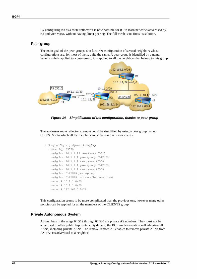
BGP4
68 Quagga Routing Configuration Guide- Version 2.12 – revision 1
By configuring rt3 as a route reflector it is now possible for rt1 to learn networks advertised by
rt2 and vice-versa, without having direct peering. The full mesh issue finds its solution.
Peer-group
The main goal of the peer-groups is to factorize configuration of several neighbors whose
configurations are, for most of them, quite the same. A peer-group is identified by a name.
When a rule is applied to a peer-group, it is applied to all the neighbors that belong to this group.
Figure 14 – Simplification of the configuration, thanks to peer-group
The au-dessus route reflector example could be simplified by using a peer group named
CLIENTS into which all the members are some route reflector clients.
rt3{myconfig-rtg-dynamic}display
router bgp 65500
neighbor 10.1.1.10 remote-as 65510
neighbor 10.1.1.2 peer-group CLIENTS
neighbor 10.1.1.2 remote-as 65500
neighbor 10.1.1.1 peer-group CLIENTS
neighbor 10.1.1.1 remote-as 65500
neighbor CLIENTS peer-group
neighbor CLIENTS route-reflector-client
network 10.1.1.0/29
network 10.1.1.8/29
network 192.168.3.0/24
This configuration seems to be more complicated than the previous one, however many other
policies can be applied for all the members of the CLIENTS group.
Private Autonomous System
AS numbers in the range 64,512 through 65,534 are private AS numbers. They must not be
advertised to other public bgp routers. By default, the BGP implementation will advertise all
ASNs, including private ASNs. The remove-remote-AS enables to remove private ASNs from
AS-PATHs advertised to a neighbor.
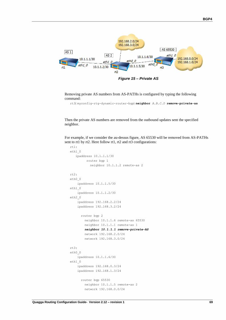
BGP4
Quagga Routing Configuration Guide- Version 2.12 – revision 1 69
Figure 15 – Private AS
Removing private AS numbers from AS-PATHs is configured by typing the following
command:
rt3{myconfig-rtg-dynamic-router-bgp}neighbor A.B.C.D remove-private-as
Then the private AS numbers are removed from the outbound updates sent the specified
neighbor.
For example, if we consider the au-dessus figure, AS 65530 will be removed from AS-PATHs
sent to rt1 by rt2. Here follow rt1, rt2 and rt3 configurations:
rt1:
eth1_0
ipaddress 10.1.1.1/30
router bgp 1
neighbor 10.1.1.2 remote-as 2
rt2:
eth0_0
ipaddress 10.1.1.5/30
eth1_0
ipaddress 10.1.1.2/30
eth2_0
ipaddress 192.168.2.2/24
ipaddress 192.168.3.2/24
router bgp 2
neighbor 10.1.1.6 remote-as 65530
neighbor 10.1.1.1 remote-as 1
neighbor 10.1.1.1 remove-private-AS
network 192.168.2.0/24
network 192.168.3.0/24
rt3:
eth0_0
ipaddress 10.1.1.6/30
eth1_0
ipaddress 192.168.0.3/24
ipaddress 192.168.1.3/24
router bgp 65530
neighbor 10.1.1.5 remote-as 2
network 192.168.0.0/24
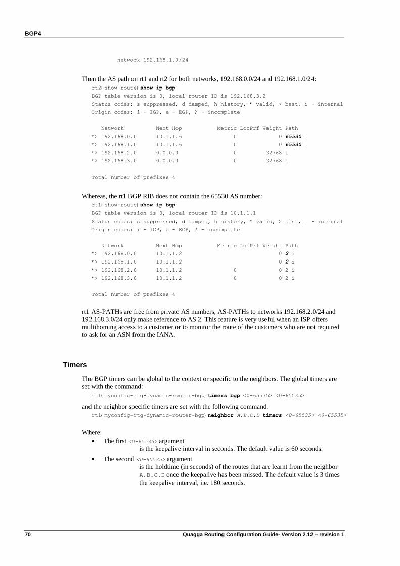
BGP4
70 Quagga Routing Configuration Guide- Version 2.12 – revision 1
network 192.168.1.0/24
Then the AS path on rt1 and rt2 for both networks, 192.168.0.0/24 and 192.168.1.0/24:
rt2{show-route}show ip bgp
BGP table version is 0, local router ID is 192.168.3.2
Status codes: s suppressed, d damped, h history, * valid, > best, i - internal
Origin codes: i - IGP, e - EGP, ? - incomplete
Network Next Hop Metric LocPrf Weight Path
*> 192.168.0.0 10.1.1.6 0 0 65530 i
*> 192.168.1.0 10.1.1.6 0 0 65530 i
*> 192.168.2.0 0.0.0.0 0 32768 i
*> 192.168.3.0 0.0.0.0 0 32768 i
Total number of prefixes 4
Whereas, the rt1 BGP RIB does not contain the 65530 AS number:
rt1{show-route}show ip bgp
BGP table version is 0, local router ID is 10.1.1.1
Status codes: s suppressed, d damped, h history, * valid, > best, i - internal
Origin codes: i - IGP, e - EGP, ? - incomplete
Network Next Hop Metric LocPrf Weight Path
*> 192.168.0.0 10.1.1.2 0 2 i
*> 192.168.1.0 10.1.1.2 0 2 i
*> 192.168.2.0 10.1.1.2 0 0 2 i
*> 192.168.3.0 10.1.1.2 0 0 2 i
Total number of prefixes 4
rt1 AS-PATHs are free from private AS numbers, AS-PATHs to networks 192.168.2.0/24 and
192.168.3.0/24 only make reference to AS 2. This feature is very useful when an ISP offers
multihoming access to a customer or to monitor the route of the customers who are not required
to ask for an ASN from the IANA.
Timers
The BGP timers can be global to the context or specific to the neighbors. The global timers are
set with the command:
rt1{myconfig-rtg-dynamic-router-bgp}timers bgp <0-65535> <0-65535>
and the neighbor specific timers are set with the following command:
rt1{myconfig-rtg-dynamic-router-bgp}neighbor A.B.C.D timers <0-65535> <0-65535>
Where:
The first <0-65535> argument
is the keepalive interval in seconds. The default value is 60 seconds.
The second <0-65535> argument
is the holdtime (in seconds) of the routes that are learnt from the neighbor
A.B.C.D once the keepalive has been missed. The default value is 3 times
the keepalive interval, i.e. 180 seconds.
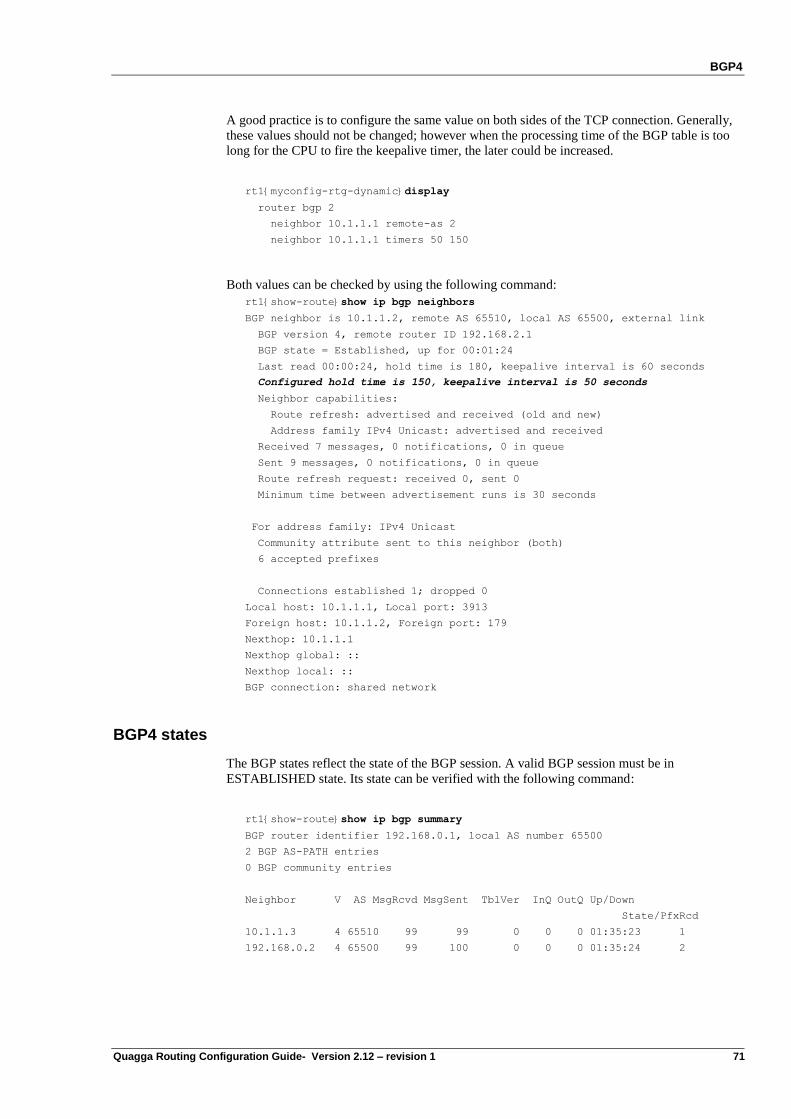
BGP4
Quagga Routing Configuration Guide- Version 2.12 – revision 1 71
A good practice is to configure the same value on both sides of the TCP connection. Generally,
these values should not be changed; however when the processing time of the BGP table is too
long for the CPU to fire the keepalive timer, the later could be increased.
rt1{myconfig-rtg-dynamic}display
router bgp 2
neighbor 10.1.1.1 remote-as 2
neighbor 10.1.1.1 timers 50 150
Both values can be checked by using the following command:
rt1{show-route}show ip bgp neighbors
BGP neighbor is 10.1.1.2, remote AS 65510, local AS 65500, external link
BGP version 4, remote router ID 192.168.2.1
BGP state = Established, up for 00:01:24
Last read 00:00:24, hold time is 180, keepalive interval is 60 seconds
Configured hold time is 150, keepalive interval is 50 seconds
Neighbor capabilities:
Route refresh: advertised and received (old and new)
Address family IPv4 Unicast: advertised and received
Received 7 messages, 0 notifications, 0 in queue
Sent 9 messages, 0 notifications, 0 in queue
Route refresh request: received 0, sent 0
Minimum time between advertisement runs is 30 seconds
For address family: IPv4 Unicast
Community attribute sent to this neighbor (both)
6 accepted prefixes
Connections established 1; dropped 0
Local host: 10.1.1.1, Local port: 3913
Foreign host: 10.1.1.2, Foreign port: 179
Nexthop: 10.1.1.1
Nexthop global: ::
Nexthop local: ::
BGP connection: shared network
BGP4 states
The BGP states reflect the state of the BGP session. A valid BGP session must be in
ESTABLISHED state. Its state can be verified with the following command:
rt1{show-route}show ip bgp summary
BGP router identifier 192.168.0.1, local AS number 65500
2 BGP AS-PATH entries
0 BGP community entries
Neighbor V AS MsgRcvd MsgSent TblVer InQ OutQ Up/Down
State/PfxRcd
10.1.1.3 4 65510 99 99 0 0 0 01:35:23 1
192.168.0.2 4 65500 99 100 0 0 0 01:35:24 2
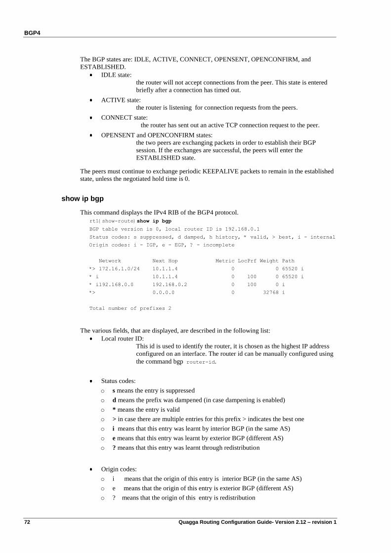
BGP4
72 Quagga Routing Configuration Guide- Version 2.12 – revision 1
The BGP states are: IDLE, ACTIVE, CONNECT, OPENSENT, OPENCONFIRM, and
ESTABLISHED.
IDLE state:
the router will not accept connections from the peer. This state is entered
briefly after a connection has timed out.
ACTIVE state:
the router is listening for connection requests from the peers.
CONNECT state:
the router has sent out an active TCP connection request to the peer.
OPENSENT and OPENCONFIRM states:
the two peers are exchanging packets in order to establish their BGP
session. If the exchanges are successful, the peers will enter the
ESTABLISHED state.
The peers must continue to exchange periodic KEEPALIVE packets to remain in the established
state, unless the negotiated hold time is 0.
show ip bgp
This command displays the IPv4 RIB of the BGP4 protocol.
rt1{show-route}show ip bgp
BGP table version is 0, local router ID is 192.168.0.1
Status codes: s suppressed, d damped, h history, * valid, > best, i - internal
Origin codes: i - IGP, e - EGP, ? - incomplete
Network Next Hop Metric LocPrf Weight Path
*> 172.16.1.0/24 10.1.1.4 0 0 65520 i
* i 10.1.1.4 0 100 0 65520 i
* i192.168.0.0 192.168.0.2 0 100 0 i
*> 0.0.0.0 0 32768 i
Total number of prefixes 2
The various fields, that are displayed, are described in the following list:
Local router ID:
This id is used to identify the router, it is chosen as the highest IP address
configured on an interface. The router id can be manually configured using
the command bgp router-id.
Status codes:
o s means the entry is suppressed
o d means the prefix was dampened (in case dampening is enabled)
o * means the entry is valid
o > in case there are multiple entries for this prefix > indicates the best one
o i means that this entry was learnt by interior BGP (in the same AS)
o e means that this entry was learnt by exterior BGP (different AS)
o ? means that this entry was learnt through redistribution
Origin codes:
o i means that the origin of this entry is interior BGP (in the same AS)
o e means that the origin of this entry is exterior BGP (different AS)
o ? means that the origin of this entry is redistribution
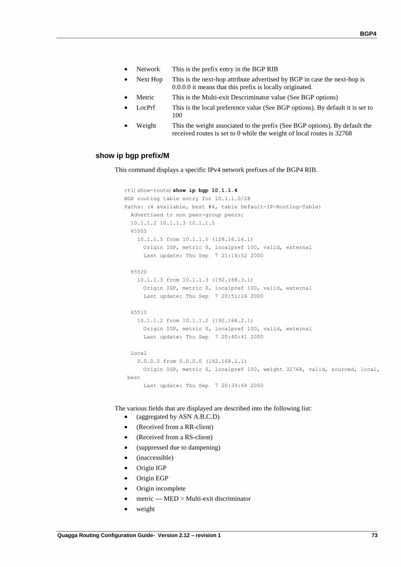
BGP4
Quagga Routing Configuration Guide- Version 2.12 – revision 1 73
Network This is the prefix entry in the BGP RIB
Next Hop This is the next-hop attribute advertised by BGP in case the next-hop is
0.0.0.0 it means that this prefix is locally originated.
Metric This is the Multi-exit Descriminator value (See BGP options)
LocPrf This is the local preference value (See BGP options). By default it is set to
100
Weight This the weight associated to the prefix (See BGP options). By default the
received routes is set to 0 while the weight of local routes is 32768
show ip bgp prefix/M
This command displays a specific IPv4 network prefixes of the BGP4 RIB.
rt1{show-route}show ip bgp 10.1.1.4
BGP routing table entry for 10.1.1.0/28
Paths: (4 available, best #4, table Default-IP-Routing-Table)
Advertised to non peer-group peers:
10.1.1.2 10.1.1.3 10.1.1.5
65505
10.1.1.5 from 10.1.1.5 (128.16.16.1)
Origin IGP, metric 0, localpref 100, valid, external
Last update: Thu Sep 7 21:14:52 2000
65520
10.1.1.3 from 10.1.1.3 (192.168.3.1)
Origin IGP, metric 0, localpref 100, valid, external
Last update: Thu Sep 7 20:51:16 2000
65510
10.1.1.2 from 10.1.1.2 (192.168.2.1)
Origin IGP, metric 0, localpref 100, valid, external
Last update: Thu Sep 7 20:40:41 2000
Local
0.0.0.0 from 0.0.0.0 (192.168.1.1)
Origin IGP, metric 0, localpref 100, weight 32768, valid, sourced, local,
best
Last update: Thu Sep 7 20:39:44 2000
The various fields that are displayed are described into the following list:
(aggregated by ASN A.B.C.D)
(Received from a RR-client)
(Received from a RS-client)
(suppressed due to dampening)
(inaccessible)
Origin IGP
Origin EGP
Origin incomplete
metric --- MED = Multi-exit discriminator
weight
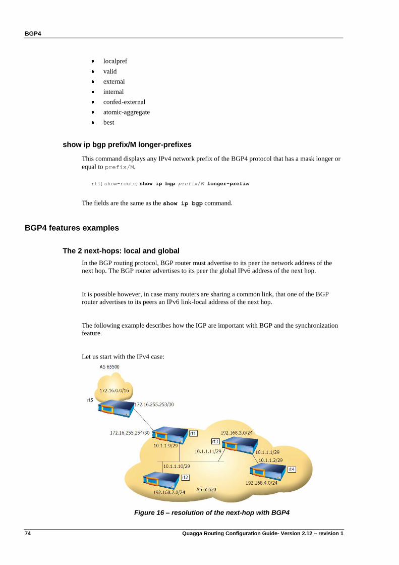
BGP4
74 Quagga Routing Configuration Guide- Version 2.12 – revision 1
localpref
valid
external
internal
confed-external
atomic-aggregate
best
show ip bgp prefix/M longer-prefixes
This command displays any IPv4 network prefix of the BGP4 protocol that has a mask longer or
equal to prefix/M.
rt1{show-route}show ip bgp prefix/M longer-prefix
The fields are the same as the show ip bgp command.
BGP4 features examples
The 2 next-hops: local and global
In the BGP routing protocol, BGP router must advertise to its peer the network address of the
next hop. The BGP router advertises to its peer the global IPv6 address of the next hop.
It is possible however, in case many routers are sharing a common link, that one of the BGP
router advertises to its peers an IPv6 link-local address of the next hop.
The following example describes how the IGP are important with BGP and the synchronization
feature.
Let us start with the IPv4 case:
Figure 16 – resolution of the next-hop with BGP4
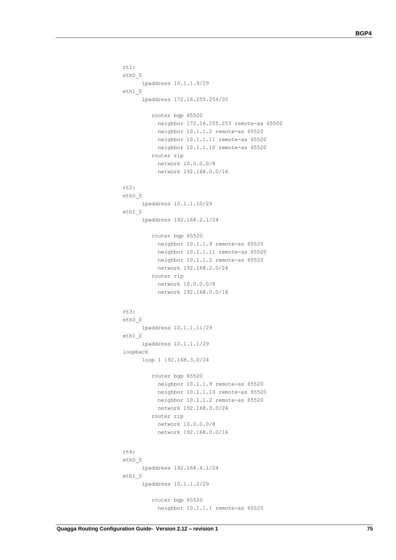
BGP4
Quagga Routing Configuration Guide- Version 2.12 – revision 1 75
rt1:
eth0_0
ipaddress 10.1.1.9/29
eth1_0
ipaddress 172.16.255.254/30
router bgp 65520
neighbor 172.16.255.253 remote-as 65500
neighbor 10.1.1.2 remote-as 65520
neighbor 10.1.1.11 remote-as 65520
neighbor 10.1.1.10 remote-as 65520
router rip
network 10.0.0.0/8
network 192.168.0.0/16
rt2:
eth0_0
ipaddress 10.1.1.10/29
eth1_0
ipaddress 192.168.2.1/24
router bgp 65520
neighbor 10.1.1.9 remote-as 65520
neighbor 10.1.1.11 remote-as 65520
neighbor 10.1.1.2 remote-as 65520
network 192.168.2.0/24
router rip
network 10.0.0.0/8
network 192.168.0.0/16
rt3:
eth0_0
ipaddress 10.1.1.11/29
eth1_0
ipaddress 10.1.1.1/29
loopback
loop 1 192.168.3.0/24
router bgp 65520
neighbor 10.1.1.9 remote-as 65520
neighbor 10.1.1.10 remote-as 65520
neighbor 10.1.1.2 remote-as 65520
network 192.168.3.0/24
router rip
network 10.0.0.0/8
network 192.168.0.0/16
rt4:
eth0_0
ipaddress 192.168.4.1/24
eth1_0
ipaddress 10.1.1.2/29
router bgp 65520
neighbor 10.1.1.1 remote-as 65520
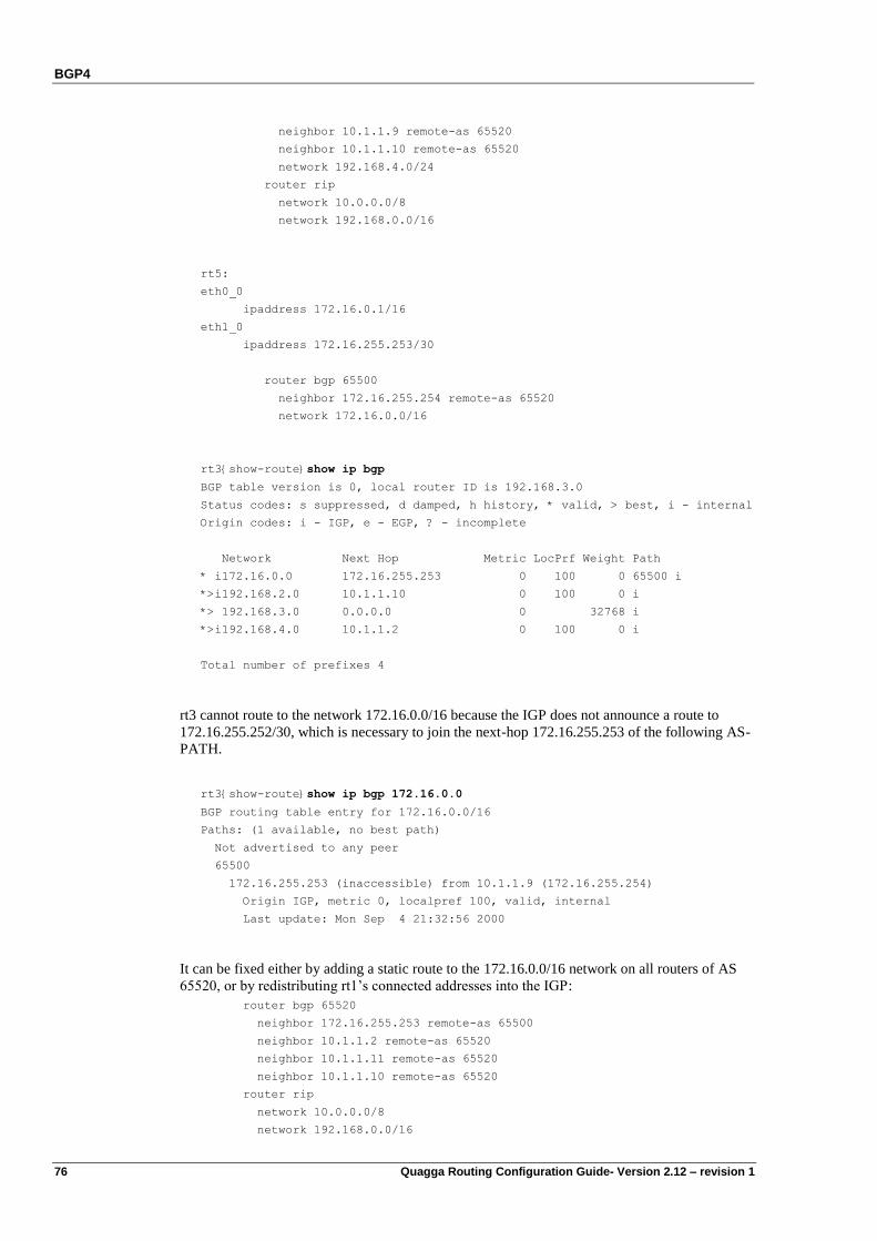
BGP4
76 Quagga Routing Configuration Guide- Version 2.12 – revision 1
neighbor 10.1.1.9 remote-as 65520
neighbor 10.1.1.10 remote-as 65520
network 192.168.4.0/24
router rip
network 10.0.0.0/8
network 192.168.0.0/16
rt5:
eth0_0
ipaddress 172.16.0.1/16
eth1_0
ipaddress 172.16.255.253/30
router bgp 65500
neighbor 172.16.255.254 remote-as 65520
network 172.16.0.0/16
rt3{show-route}show ip bgp
BGP table version is 0, local router ID is 192.168.3.0
Status codes: s suppressed, d damped, h history, * valid, > best, i - internal
Origin codes: i - IGP, e - EGP, ? - incomplete
Network Next Hop Metric LocPrf Weight Path
* i172.16.0.0 172.16.255.253 0 100 0 65500 i
*>i192.168.2.0 10.1.1.10 0 100 0 i
*> 192.168.3.0 0.0.0.0 0 32768 i
*>i192.168.4.0 10.1.1.2 0 100 0 i
Total number of prefixes 4
rt3 cannot route to the network 172.16.0.0/16 because the IGP does not announce a route to
172.16.255.252/30, which is necessary to join the next-hop 172.16.255.253 of the following AS-
PATH.
rt3{show-route}show ip bgp 172.16.0.0
BGP routing table entry for 172.16.0.0/16
Paths: (1 available, no best path)
Not advertised to any peer
65500
172.16.255.253 (inaccessible) from 10.1.1.9 (172.16.255.254)
Origin IGP, metric 0, localpref 100, valid, internal
Last update: Mon Sep 4 21:32:56 2000
It can be fixed either by adding a static route to the 172.16.0.0/16 network on all routers of AS
65520, or by redistributing rt1‟s connected addresses into the IGP:
router bgp 65520
neighbor 172.16.255.253 remote-as 65500
neighbor 10.1.1.2 remote-as 65520
neighbor 10.1.1.11 remote-as 65520
neighbor 10.1.1.10 remote-as 65520
router rip
network 10.0.0.0/8
network 192.168.0.0/16
BGP4
Quagga Routing Configuration Guide- Version 2.12 – revision 1 77
redistribute connected
Note Trying to solve the problem by adding the line network 172.16.0.0/16 or network eth1_0 in
the RIP configuration would be an error: it would result in activating RIP on rt1‟s external
interface, which would inject AS 65520‟s IGP routes into AS 65500‟s IGP.
Flush BGP4 sessions
If you have configured or changed a policy with a BGP neighbor, you should manually reset a
BGP session. You may also want to reset sessions each time you think there is a problem of
integrity with neighbor‟s information.
The following command is used for this purpose:
rt1{}flush bgp [ip] A.B.C.D|ASN|all|external|peer-group|view [param]
Where:
A.B.C.D is the IPv4 address of the remote BGP peer
ASN is a peer AS number
all represents all remote BGP peers
external represents external BGP peers
peer-group represents members of peer-group
view set view name
param is a parameter for update direction or reconfig: in|out|soft|rsclient
o in Inbound update
o out Outbound update
o soft Soft reconfig
o rsclient Soft reconfig for rsclient RIB
If you used the keyword soft, the session is not reset but all routing updates are resent, therefore
the following command is generally advised when you configured a route-map or a filter and
you want to update the neighbor‟s BGP data:
rt1{}flush bgp A.B.C.D soft out
Another example is to use the following command to reset a session with a specific neighbor.
The relationship will become idle and then be established again:
rt1{}flush bgp A.B.C.D out
Conversely, keyword in is used for inbound reconfiguration. Example:
rt1{}flush bgp A.B.C.D soft in
Before using the command flush, you may need to configure inbound soft reconfiguration with
the considered neighbor (see au-dessous for more information).
Route refresh
Route refresh is an extension to BGP that is defined in RFC 2918. Using this feature, a BGP
router can request a complete retransmission of the peer‟s routing information without tearing
down and reestablishing the BGP session, saving a route flap. It is used to facilitate routing
policy changes, without storing an unmodified copy of the peer‟s routes on the local router to
save RAM. The capability must be supported by both routers of a BGP session. When both
routers in the peering session support this extension, each router will respond to requests issued
from the peer without operator intervention.
BGP4
78 Quagga Routing Configuration Guide- Version 2.12 – revision 1
Route Refresh is enabled by default.
When the command flush is used, Route Refresh messages are sent to the peers, the router
receives one or more Update packets with all the routes of the Adj-RIB-Out. Example:
rt1{}flush bgp all soft in
rt1{show-route}show route
rt1{show-route}show ip bgp neighbors
BGP neighbor is 10.23.0.1, remote AS 1, local AS 2, external link
BGP version 4, remote router ID 10.23.0.1
BGP state = Established, up for 00:01:49
Last read 00:00:49, hold time is 180, keepalive interval is 60 seconds
Neighbor capabilities:
Route refresh: advertised and received(old & new)
Address family IPv4 Unicast: advertised and received
Message statistics:
Inq depth is 0
Outq depth is 0
Sent Rcvd
Opens: 1 0
Notifications: 0 0
Updates: 4 2
Keepalives: 3 2
Route Refresh: 1 0
Capability: 0 0
Total: 9 4
Soft reconfiguration
When using the BGP soft reconfiguration, all the updates received from the neighbors will be
stored unmodified regardless of the inbound policy. When soft-reconfiguration is done later the
stored information will be used to generate a new set of inbound updates. The feature should be
used on routers that have enough RAM.
The command to enable soft reconfiguration with a peer can be used as follows:
rt1{myconfig-rtg-dynamic-router-bgp}neighbor A.B.C.D soft-reconfiguration inbound
After this command, you may for example define an access list to accept some routes from a
neighbor A.B.C.D:
rt1{myconfig-rtg-dynamic}ip access-list my_acl permit 10.24.0.0/24
Apply to the incoming routes the distribute list policy name based on this access-list:
rt1{myconfig-rtg-dynamic-router-bgp}neighbor A.B.C.D distribute-list my_acl in
A soft reset uses stored prefix information to reconfigure and activate BGP routing tables
without tearing down existing peering session. No route refresh packet is sent to the peer during
soft reconfiguration is enabled.
When the command flush is used, if Soft Reconfiguration is enabled, Route Refresh message is
not sent :
rt1{}flush bgp A.B.C.D soft in
rt1{show-route}show route
rt1{show-route}show ip bgp neighbors
...
Route Refresh: 1 0
Route Refresh count is not incremented.
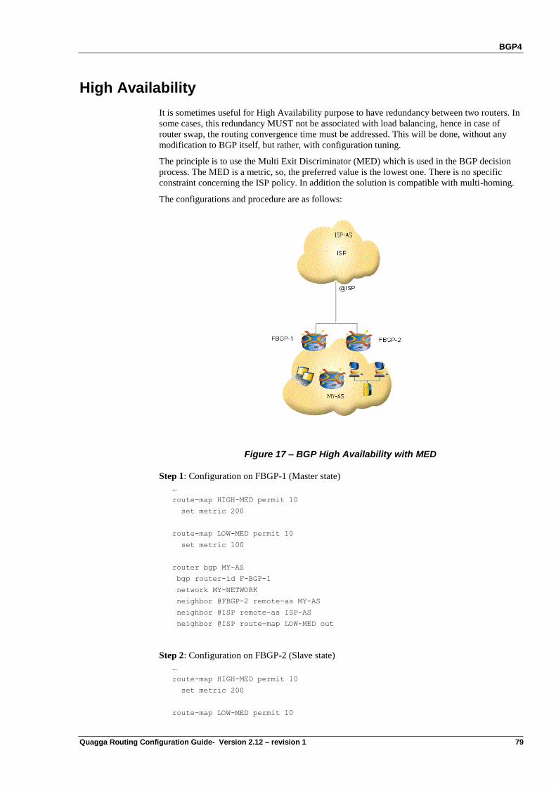
BGP4
Quagga Routing Configuration Guide- Version 2.12 – revision 1 79
High Availability
It is sometimes useful for High Availability purpose to have redundancy between two routers. In
some cases, this redundancy MUST not be associated with load balancing, hence in case of
router swap, the routing convergence time must be addressed. This will be done, without any
modification to BGP itself, but rather, with configuration tuning.
The principle is to use the Multi Exit Discriminator (MED) which is used in the BGP decision
process. The MED is a metric, so, the preferred value is the lowest one. There is no specific
constraint concerning the ISP policy. In addition the solution is compatible with multi-homing.
The configurations and procedure are as follows:
Figure 17 – BGP High Availability with MED
Step 1: Configuration on FBGP-1 (Master state)
…
route-map HIGH-MED permit 10
set metric 200
route-map LOW-MED permit 10
set metric 100
router bgp MY-AS
bgp router-id F-BGP-1
network MY-NETWORK
neighbor @FBGP-2 remote-as MY-AS
neighbor @ISP remote-as ISP-AS
neighbor @ISP route-map LOW-MED out
Step 2: Configuration on FBGP-2 (Slave state)
…
route-map HIGH-MED permit 10
set metric 200
route-map LOW-MED permit 10
BGP4
80 Quagga Routing Configuration Guide- Version 2.12 – revision 1
set metric 100
router bgp MY-AS
bgp router-id @FBGP-1
network MY-NETWORK
neighbor @FBGP-1 remote-as MY-AS
neighbor @ISP remote-as ISP-AS
neighbor @ISP route-map HIGH-MED out
Step 3: How to switch from Slave to Master
FBGP-2{myconfig-rtg-dynamic}router bgp MY-AS
FBGP-2{myconfig-rtg-dynamic-router-ospf}delete neighbor @ISP route-map HIGH-MED
out
FBGP-2{myconfig-rtg-dynamic-router-bgp}neighbor @ISP route-map LOW-MED out
FBGP-2{myconfig-rtg-dynamic-router-bgp}exit
...
FBGP-2{}flush ip bgp external out
The last command clear is important to reset the information.
BGP4 Security
BGP is used for inter-domain routing, so it is a critical service for the Internet infrastructure.
Therefore security aspect of BGP, with valid routing advertisement, is a high issue and the
current system is highly vulnerable to human errors, as well as a wide range of attacks.
Filtering is currently the most used mechanism. Nevertheless complementary security features
may be used to add security with BGP. Thus, in some cases MD5 authentication may be used to
control BGP routing information advertisement, as described for RIP and OSPF.
BGP4 Filtering
Two types of BGP-4 filtering method exist:
Distribute-list : Allows filtering on prefix basis,
AS-PATH access-list : Filters all networks in relation with a particular AS number.
BGP-4 Distribute list configuration
To configure a distribute-list, two steps are required:
Step 1: Configure the IPv4 access-list
rt1{myconfig-rtg-dynamic}ip access-list ACCESS-LIST-NAME {permit|deny}
A.B.C.D/M
Step 2: Apply this access-list to a neighbor
rt1{myconfig-rtg-dynamic-router-bgp}neighbor A.B.C.D distribute-list
ACCESS-LIST-NAME {in|out}
Note The below IPv4 prefix-list should be preferred to the IPv4 access-lists.
BGP4
Quagga Routing Configuration Guide- Version 2.12 – revision 1 81
Distribute-list configuration example
You can give a description to your access list by typing the command
rt1{myconfig-rtg-dynamic}ip access-list remark description
If we consider two BGP peers rt1 and rt2.
rt1 is advertising two networks 10.1.1.0/28 and 192.168.1.0/24
On the rt1 router we filter the advertisement of 192.168.1.0/24
rt1{myconfig-rtg-dynamic}display
ip access-list MY-LIST deny 192.168.1.0/24
ip access-list MY-LIST permit any
#
router bgp 65510
neighbor 10.1.1.2 remote-as 65520
neighbor 10.1.1.2 distribute-list MY-LIST out
network 10.1.1.0/28
network 192.168.1.0/24
On rt2 router we check the bgp table
rt2{show-route}show ip bgp
BGP table version is 0, local router ID is 192.168.2.1
Status codes: s suppressed, d damped, h history, * valid, > best, i - internal
Origin codes: i - IGP, e - EGP, ? - incomplete
Network Next Hop Metric LocPrf Weight Path
*> 10.1.1.0/28 10.1.1.1 0 0 65510 i
Total number of prefixes 1
rt2 doesn‟t see the 192.168.1.0 prefix because it is filtered by rt1
Note that by typing the command show ip bgp neighbor you can check which filtering rules are
applied to a given neighbor.
rt1{show-route}show ip bgp neighbor 10.1.1.2
….output omitted
Outbound path policy configured
Outgoing update network filter list is *my-list
Introduction to the IPv4 prefix-lists
A prefix filter is more powerful than an access-list filter in order to process the network prefixes
In comparison to access-list prefix-list have the following advantages:
Can process a range of values
Performance improvement in prefix lookup of large lists
More flexible
BGP4
82 Quagga Routing Configuration Guide- Version 2.12 – revision 1
Prefix List Rules
Filtering by prefix list involves the following rules :
An empty prefix list permits all prefixes.
An implicit deny is assumed if a given prefix does not match any entries of a prefix list.
When multiple entries of a prefix list match a given prefix, the longest match is chosen.
The router prefix-list lookup begins at the top woth sequence number 1, if a match
occurs then the router do not go through the rest of the prefix list
The syntax to define a prefix filter is:
rt1{myconfig-rtg-dynamic}ip prefix-list BGP-FILTER-NAME
seq N {permit|deny} PREFIX/M [ge A] [le B]
Where:
N is the sequence of the rule named BGP-FILTER-NAME
PREFIX/M is the network prefix and M the length of the mask.
A and B are any optional integers up to 32 that can be used in order to form a block of
prefixes. A, B and M are such as:
o M < A
o M < B
o A B
o M < A B 32
Let‟s P1/m be a network prefix that matches PREFIX/M. For example PREFIX/M could be
192.168.0.0/16 and P1/m could be 192.168.10.0/24.
Moreover, if A and B are defined, P1/M matches this rule if M is greater or equal than A and if M
is less or equal to B (A M B). For example 192.168.10.0/24 matches the rule 5, however it
does not match the rule 10.
rt2{myconfig-rtg-dynamic}ip prefix-list PREFIX-FILTER-NAME
seq 5 permit 192.168.0.0/16 ge 17 le 25
rt2{myconfig-rtg-dynamic}ip prefix-list PREFIX-FILTER-NAME
seq 10 permit 192.168.0.0/16 le 23
The IPv4 prefix lists can be used in many cases:
neighbor A.B.C.D prefix-list FILTER-NAME {in|out}
neighbor capability orf prefix-list FILTER-NAME send|receive|both
route-map:
o match ip address prefix-list FILTER-NAME2
show ip bgp (display filters):
2 The command „match ip address‟ can be used with an access-list too. However, you can check
that the syntax is not exactly the same:
match ip address prefix-list FILTER-NAME
vs. match ip address ACCESS-LIST-NAME
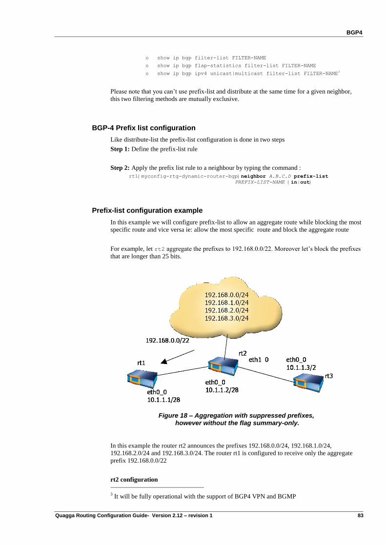
BGP4
Quagga Routing Configuration Guide- Version 2.12 – revision 1 83
o show ip bgp filter-list FILTER-NAME
o show ip bgp flap-statistics filter-list FILTER-NAME
o show ip bgp ipv4 unicast|multicast filter-list FILTER-NAME3
Please note that you can‟t use prefix-list and distribute at the same time for a given neighbor,
this two filtering methods are mutually exclusive.
BGP-4 Prefix list configuration
Like distribute-list the prefix-list configuration is done in two steps
Step 1: Define the prefix-list rule
Step 2: Apply the prefix list rule to a neighbour by typing the command :
rt1{myconfig-rtg-dynamic-router-bgp}neighbor A.B.C.D prefix-list
PREFIX-LIST-NAME {in|out}
Prefix-list configuration example
In this example we will configure prefix-list to allow an aggregate route while blocking the most
specific route and vice versa ie: allow the most specific route and block the aggregate route
For example, let rt2 aggregate the prefixes to 192.168.0.0/22. Moreover let‟s block the prefixes
that are longer than 25 bits.
Figure 18 – Aggregation with suppressed prefixes, however without the flag summary-only.
In this example the router rt2 announces the prefixes 192.168.0.0/24, 192.168.1.0/24,
192.168.2.0/24 and 192.168.3.0/24. The router rt1 is configured to receive only the aggregate
prefix 192.168.0.0/22
rt2 configuration
3 It will be fully operational with the support of BGP4 VPN and BGMP
BGP4
84 Quagga Routing Configuration Guide- Version 2.12 – revision 1
router bgp 65520
neighbor 10.1.1.1 remote-as 65510
aggregate-address 192.168.2.0/24
network 10.1.1.0/28
network 192.168.0.0/24
network 192.168.1.0/24
network 192.168.2.0/24
network 192.168.3.0/24
We configure the router rt1 to accept only the aggregate prefix
rt1 configuration
rt1{myconfig-rtg-dynamic}display
ip prefix-list aggregate seq 5 permit 192.168.0.0/22
router bgp 65510
neighbor 10.1.1.2 remote-as 65520
neighbor 10.1.1.2 prefix-list aggregate in
If we look at rt1 bgp table, there is only the aggregate network 192.168.2.0/24
rt1{show-route}show ip bgp
BGP table version is 0, local router ID is 192.168.1.1
Status codes: s suppressed, d damped, h history, * valid, > best, i - internal
Origin codes: i - IGP, e - EGP, ? - incomplete
Network Next Hop Metric LocPrf Weight Path
*> 192.168.0.0/22 10.1.1.2 0 65520 i
Total number of prefixes 1
We can also check on rt1 the the prefix list called aggregate is applied on incoming updates
rt1{show-route}show ip bgp neighbor
….output omitted
Incoming update prefix filter list is *aggregate
1 accepted prefixes
…
Please note that prefix list configured on a router can be examined by typing the command:
rt1{show-route}show ip prefix-list [detail]
rt1{show-route}show ip prefix-list
BGP: ip prefix-list aggregate: 1 entries
seq 5 permit 192.168.0.0/22
If we suppose now that rt1 filters only the aggregate prefix, and let the specific prefixes, then the
prefix list to configure is:
rt1{myconfig-rtg-dynamic}display
ip prefix-list specific seq 5 permit 192.168.0.0/22 ge 23
We can check that only the specific routes are accepted
rt1{show-route}show ip bgp
BGP table version is 0, local router ID is 192.168.1.1
Status codes: s suppressed, d damped, h history, * valid, > best, i - internal
Origin codes: i - IGP, e - EGP, ? - incomplete
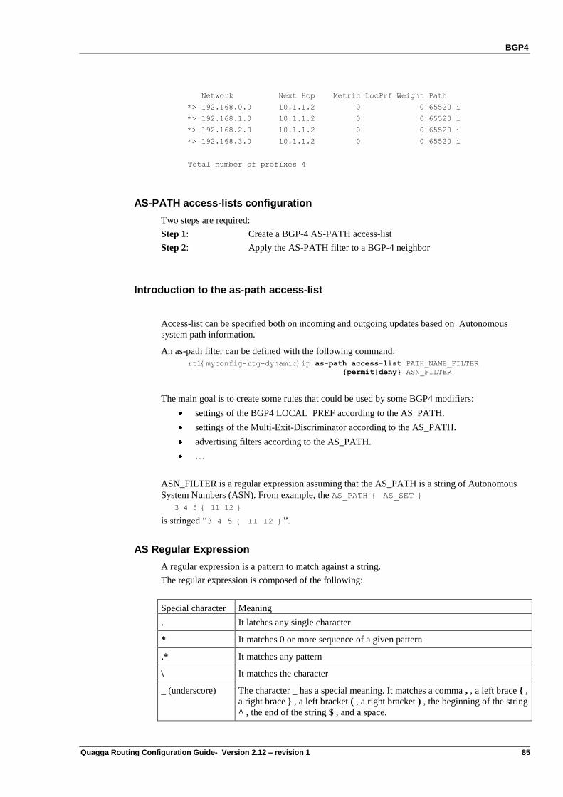
BGP4
Quagga Routing Configuration Guide- Version 2.12 – revision 1 85
Network Next Hop Metric LocPrf Weight Path
*> 192.168.0.0 10.1.1.2 0 0 65520 i
*> 192.168.1.0 10.1.1.2 0 0 65520 i
*> 192.168.2.0 10.1.1.2 0 0 65520 i
*> 192.168.3.0 10.1.1.2 0 0 65520 i
Total number of prefixes 4
AS-PATH access-lists configuration
Two steps are required:
Step 1: Create a BGP-4 AS-PATH access-list
Step 2: Apply the AS-PATH filter to a BGP-4 neighbor
Introduction to the as-path access-list
Access-list can be specified both on incoming and outgoing updates based on Autonomous
system path information.
An as-path filter can be defined with the following command:
rt1{myconfig-rtg-dynamic}ip as-path access-list PATH_NAME_FILTER
{permit|deny} ASN_FILTER
The main goal is to create some rules that could be used by some BGP4 modifiers:
settings of the BGP4 LOCAL_PREF according to the AS_PATH.
settings of the Multi-Exit-Discriminator according to the AS_PATH.
advertising filters according to the AS_PATH.
…
ASN_FILTER is a regular expression assuming that the AS_PATH is a string of Autonomous
System Numbers (ASN). From example, the AS_PATH { AS_SET }
3 4 5 { 11 12 }
is stringed “3 4 5 { 11 12 }”.
AS Regular Expression
A regular expression is a pattern to match against a string.
The regular expression is composed of the following:
Special character Meaning
. It latches any single character
* It matches 0 or more sequence of a given pattern
.* It matches any pattern
\ It matches the character
_ (underscore) The character _ has a special meaning. It matches a comma , , a left brace { ,
a right brace } , a left bracket ( , a right bracket ) , the beginning of the string
^ , the end of the string $ , and a space.
BGP4
86 Quagga Routing Configuration Guide- Version 2.12 – revision 1
^ (caret) It matches the beginning of the string.
$ (dollar) It matches the end of the string.
( N | M | … ) It matches either N, M or …
For example:
Let‟s match any BGP4 vectors containing the 1234 ASN:
rt1{myconfig-rtg-dynamic}ip as-path access-list TEST permit _1234_
Let‟s match any BGP4 vectors starting with the 3 ASN:
rt1{myconfig-rtg-dynamic}ip as-path access-list TEST permit ^3_
Note The regular expression “^3” matches any numbers starting with the following figure: 3, 30, 31,
…
The AS 3 is one of our neighbors.
Let‟s match any BGP4 vectors ending with the 4 ASN:
rt1{myconfig-rtg-dynamic}ip as-path access-list TEST permit _4$
Note The regular expression “4$” matches any number ending with the following figure: 4, 14, 24, …
The AS 4 is the Autonomous System that originates the AS path.
Let‟s match any BGP4 vectors originated from our AS:
rt1{myconfig-rtg-dynamic}ip as-path access-list TEST permit ^$
Let‟s match any BGP4 vectors containing the 3 or 4 ASN:
rt1{myconfig-rtg-dynamic}ip as-path access-list TEST permit (_3_|_4_)
Note It could be simpler to split this rule: rt1{myconfig-rtg-dynamic}ip as-path access-list TEST permit _3_
rt1{myconfig-rtg-dynamic}ip as-path access-list TEST permit _4_
The as-path filters can be used in two cases:
neighbor A.B.C.D filter-list AS-PATH-FILTER-NAME {in|out}
route-map:
o match as-path AS-PATH-FILTER-NAME
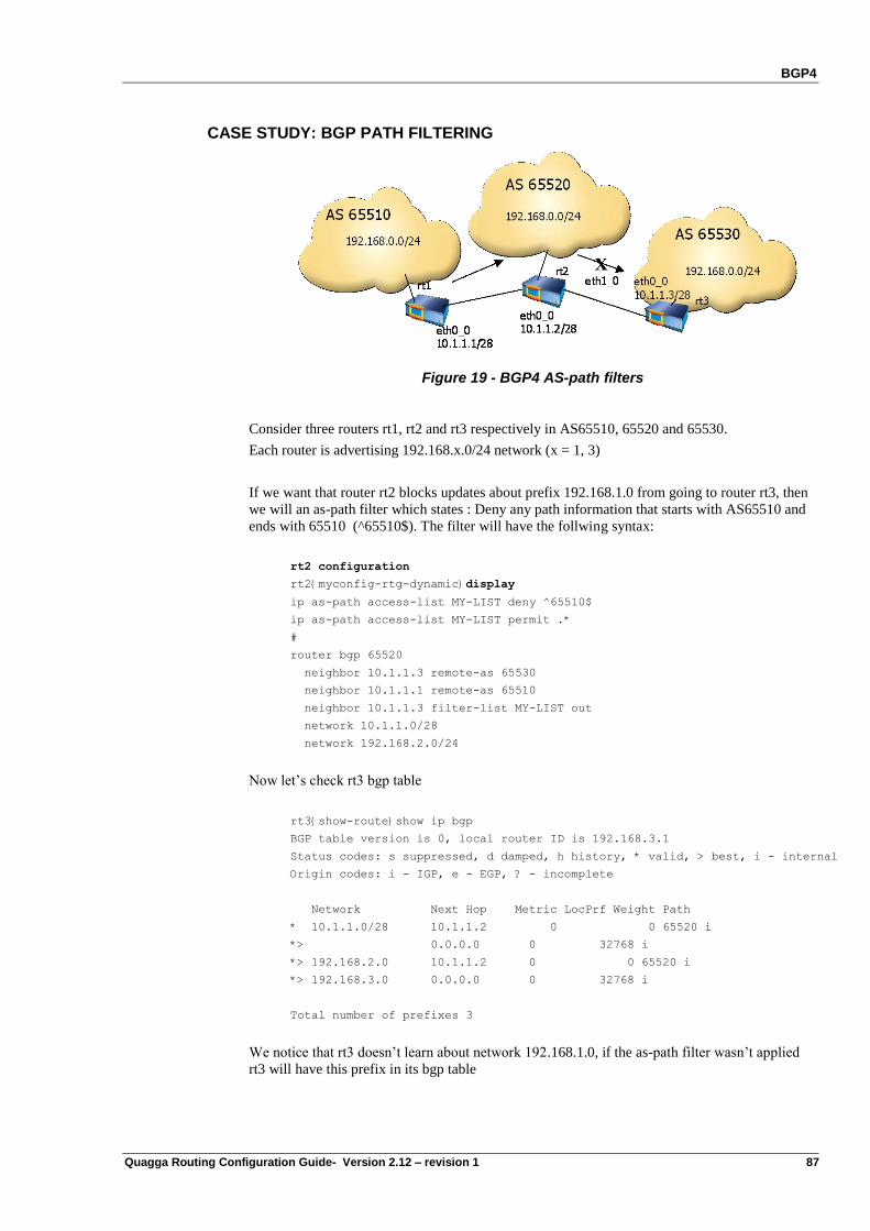
BGP4
Quagga Routing Configuration Guide- Version 2.12 – revision 1 87
CASE STUDY: BGP PATH FILTERING
Figure 19 - BGP4 AS-path filters
Consider three routers rt1, rt2 and rt3 respectively in AS65510, 65520 and 65530.
Each router is advertising 192.168.x.0/24 network (x = 1, 3)
If we want that router rt2 blocks updates about prefix 192.168.1.0 from going to router rt3, then
we will an as-path filter which states : Deny any path information that starts with AS65510 and
ends with 65510 (^65510$). The filter will have the follwing syntax:
rt2 configuration
rt2{myconfig-rtg-dynamic}display
ip as-path access-list MY-LIST deny ^65510$
ip as-path access-list MY-LIST permit .*
#
router bgp 65520
neighbor 10.1.1.3 remote-as 65530
neighbor 10.1.1.1 remote-as 65510
neighbor 10.1.1.3 filter-list MY-LIST out
network 10.1.1.0/28
network 192.168.2.0/24
Now let‟s check rt3 bgp table
rt3{show-route}show ip bgp
BGP table version is 0, local router ID is 192.168.3.1
Status codes: s suppressed, d damped, h history, * valid, > best, i - internal
Origin codes: i - IGP, e - EGP, ? - incomplete
Network Next Hop Metric LocPrf Weight Path
* 10.1.1.0/28 10.1.1.2 0 0 65520 i
*> 0.0.0.0 0 32768 i
*> 192.168.2.0 10.1.1.2 0 0 65520 i
*> 192.168.3.0 0.0.0.0 0 32768 i
Total number of prefixes 3
We notice that rt3 doesn‟t learn about network 192.168.1.0, if the as-path filter wasn‟t applied
rt3 will have this prefix in its bgp table
BGP4
88 Quagga Routing Configuration Guide- Version 2.12 – revision 1
Introduction to the communities filters
The attribute „community‟ permits to group destinations in a community and apply routing
decisions. It is an optional, global transitive attribute in the numerical range of 1 to
4,294,967,200. Based on the community, you can control the routing information .In BGP there
are some predefined well known communities which are:
no-export : The routes of this community must not be advertised to external peer
no-advertise : The routes must not be advertised to any peer
internet : The routes may be advertised to any peer
local-AS: Used in confederation to avoid sending packets outside the local AS
Note To set a community attribute it is recommended to use route-maps. Please note that in general
BGP community has the form of AS:NN where AS is the autonomous system number, and NN
is a number.
The community attribute is sent to neighbors by default with the option both (standard and
extended commnunity):
rt1{myconfig-rtg-dynamic-router-bgp}neighbor A.B.C.D send-community
{both|extended|standard}
Where:
A.B.C.D is the IP address of the remote BGP peer
both Send Standard and Extended Community attributes
extended Send Standard Community attributes
standard Send Extended Community attributes
You can check the community parameters thanks to the „show‟ command:
rt1{myconfig-rtg-dynamic-router-bgp}neighbor 10.23.7.207 send-community
rt1{show-route}show ip bgp neighbors
BGP neighbor is 10.23.7.207, remote AS 2, local AS 1, external link
BGP version 4, remote router ID 2.2.2.2
BGP state = Established, up for 00:00:09
Last read 00:00:09, hold time is 180, keepalive interval is 60 seconds
Neighbor capabilities:
Route refresh: advertised and received(old & new)
Address family IPv4 Unicast: advertised and received
Message statistics:
Inq depth is 0
Outq depth is 0
Sent Rcvd
Opens: 1 0
Notifications: 0 0
Updates: 1 0
Keepalives: 2 1
Route Refresh: 0 0
Capability: 0 0
Total: 4 1
Minimum time between advertisement runs is 30 seconds
For address family: IPv4 Unicast
Community attribute sent to this neighbor(both) <====="send-community both"
0 accepted prefixes
…
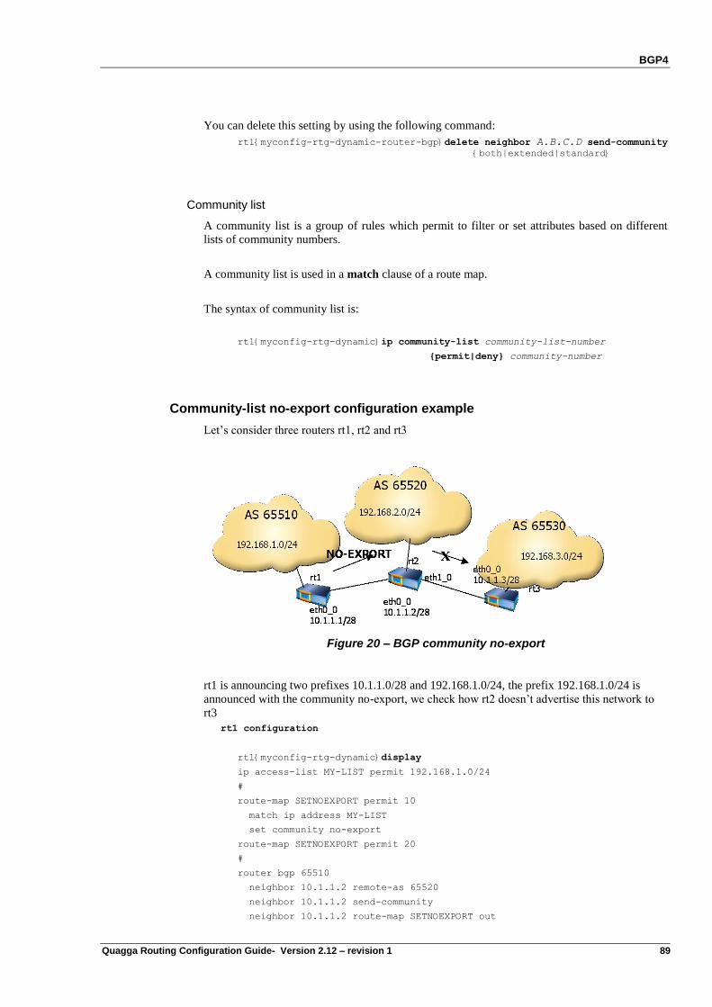
BGP4
Quagga Routing Configuration Guide- Version 2.12 – revision 1 89
You can delete this setting by using the following command:
rt1{myconfig-rtg-dynamic-router-bgp}delete neighbor A.B.C.D send-community
{both|extended|standard}
Community list
A community list is a group of rules which permit to filter or set attributes based on different
lists of community numbers.
A community list is used in a match clause of a route map.
The syntax of community list is:
rt1{myconfig-rtg-dynamic}ip community-list community-list-number
{permit|deny} community-number
Community-list no-export configuration example
Let‟s consider three routers rt1, rt2 and rt3
Figure 20 – BGP community no-export
rt1 is announcing two prefixes 10.1.1.0/28 and 192.168.1.0/24, the prefix 192.168.1.0/24 is
announced with the community no-export, we check how rt2 doesn‟t advertise this network to
rt3
rt1 configuration
rt1{myconfig-rtg-dynamic}display
ip access-list MY-LIST permit 192.168.1.0/24
#
route-map SETNOEXPORT permit 10
match ip address MY-LIST
set community no-export
route-map SETNOEXPORT permit 20
#
router bgp 65510
neighbor 10.1.1.2 remote-as 65520
neighbor 10.1.1.2 send-community
neighbor 10.1.1.2 route-map SETNOEXPORT out
BGP4
90 Quagga Routing Configuration Guide- Version 2.12 – revision 1
network 10.1.1.0/28
network 192.168.1.0/24
If we check rt2 bgp table we have
rt2{show-route}show ip bgp
BGP table version is 0, local router ID is 192.168.2.1
Status codes: s suppressed, d damped, h history, * valid, > best, i - internal
Origin codes: i - IGP, e - EGP, ? - incomplete
Network Next Hop Metric LocPrf Weight Path
* 10.1.1.0/28 10.1.1.1 0 0 65510 i
*> 0.0.0.0 0 32768 i
*> 192.168.1.0 10.1.1.1 0 0 65510 i
*> 192.168.2.0 0.0.0.0 0 32768 i
Total number of prefixes 3
Now if we check rt3 bgp table
rt3{show-route}show ip bgp
BGP table version is 0, local router ID is 192.168.3.1
Status codes: s suppressed, d damped, h history, * valid, > best, i - internal
Origin codes: i - IGP, e - EGP, ? - incomplete
Network Next Hop Metric LocPrf Weight Path
*> 10.1.1.0/28 10.1.1.2 0 0 65520 i
*> 192.168.2.0 10.1.1.2 0 0 65520 i
Total number of prefixes 2
We notice that the network 192.168.1.0/24 is not advertised from rt2 to rt3.
To check rt2 community type the command show ip bgp community
rt2{show-route}show ip bgp community
BGP table version is 0, local router ID is 192.168.2.1
Status codes: s suppressed, d damped, h history, * valid, > best, i - internal
Origin codes: i - IGP, e - EGP, ? - incomplete
Network Next Hop Metric LocPrf Weight Path
*> 192.168.1.0 10.1.1.1 0 0 65510 i
Total number of prefixes 1
BGP4 Authentication
BGP4 authentication is using MD5 (Message Digest 5). This feature relies on the Operating
System support for the TCP MD5 signature option as proposed in the RFC2385. This OS option
is used with the BSD-like configuration API.
The command format for BGP4 MD5 is as follows:
rt1{myconfig-rtg-dynamic-router-bgp}neighbor A.B.C.D remote-as ASN
rt1{myconfig-rtg-dynamic-router-bgp}neighbor A.B.C.D password my-secret
Where:
A.B.C.D is the IPv4 address of the remote BGP router

BGP4
Quagga Routing Configuration Guide- Version 2.12 – revision 1 91
ASN is the AS number of the remote BGP router
my-secret is the password shared with the remote BGP router
For information, when analyzing the BGP packets with the sniffer “tethereal”, it is possible to
verify that the option is taken in account:
Host# tethereal -r bgpmd5.pcap -V
(…)
Transmission Control Protocol, Src Port: 32770 (32770), Dst Port: bgp (179), Seq:
4043121790, Ack: 1396620414, Len: 19
Source port: 32770 (32770)
Destination port: bgp (179)
Sequence number: 4043121790
Next sequence number: 4043121809
Acknowledgement number: 1396620414
Header length: 52 bytes
Flags: 0x0018 (PSH, ACK)
0... .... = Congestion Window Reduced (CWR): Not set
.0.. .... = ECN-Echo: Not set
..0. .... = Urgent: Not set
...1 .... = Acknowledgment: Set
.... 1... = Push: Set
.... .0.. = Reset: Not set
.... ..0. = Syn: Not set
.... ...0 = Fin: Not set
Window size: 1460
Checksum: 0x2cbe (correct)
Options: (32 bytes)
NOP
NOP
Time stamp: tsval 77100, tsecr 70634
NOP
NOP
TCP MD5 signature
Border Gateway Protocol
KEEPALIVE Message
Marker: 16 bytes
Length: 19 bytes
Type: KEEPALIVE Message (4)
(…)
BGP Graceful Restart Capability
Usually when BGP on a router restarts, all the BGP peers detect that the session went down, and
then came up. This "down/up" transition results in a "routing flap" and causes BGP route re-
computation, generation of BGP routing updates and flap the forwarding tables. It could spread
across multiple routing domains. Such routing flaps may create transient forwarding blackholes
and/or transient forwarding loops. They also consume resources on the control plane of the
routers affected by the flap. As such they are detrimental to the overall network performance.
BGP4
92 Quagga Routing Configuration Guide- Version 2.12 – revision 1
This feature proposes a mechanism for BGP that would help minimize the negative effects on
routing caused by BGP restart. The graceful restart capabilities (code-64) will be exchanged
between the BGP speakers through the open messages. Routes advertised by the restarting
speaker will become „stale‟ in the peer speakers‟ routing table. On expiry of „restart time‟ the
stale routes will be deleted if the restarting speaker does not come up. Once the restarting
speaker re-establish the BGP session within the „restart time‟ the stale routes will be converted
to normal routes. Traffic flow through the stale routes will not be stopped while the BGP
speaker is restarting.
rt1{myconfig-rtg-dynamic-router-bgp}bgp graceful-restart [restart-time RT ]
where:
RT is the restart time in 1-3600 seconds; default is 180 seconds. It is used to
set the max time to hold onto restarting peer's stale paths before receiving
OPEN message.
rt1{myconfig-rtg-dynamic-router-bgp}bgp graceful-restart [stalepath-time ST ]
where:
ST is the stalepath time in 1-3600 seconds, default is 300 seconds. It is used to
set the max time to hold onto restarting peer's stale paths before receiving
End-of-RIB marker message.
To disable the capability, enter the following command:
rt1{myconfig-rtg-dynamic-router-bgp}delete bgp graceful-restart[restart-time RT ]
[stalepath-time ST ]
BGP Backdoor
Backdoor is the concept, which allows a BGP speaker to use an IGP instead of eBGP to learn a
particular route. If a BGP speaker is connected in such a way that it can learn a particular
prefix/network through IGP (OSPF, RIP,…) as well as through eBGP, in normal condition the
preferred route is eBGP as the administrative distance of eBGP (20) is low when compared to
the IGP route (110 - OSPF, 120 - RIP, …). Using the „backdoor‟ command for that particular
network will change the administrative distance of eBGP to a higher unpreferred value (200)
and make IGP as preferred route.
When a network is configured with „backdoor‟ command then it will be treated as a local entry
and will not be advertised to the BGP peers as any other normal BGP route. The command
format for BGP4 „backdoor‟ is as follows:
rt1{myconfig-rtg-dynamic-router-bgp}network A.B.C.D[/M] backdoor
where:
A.B.C.D/M is the network and mask configured with „backdoor‟
To disable the backdoor, enter the following command:
rt1{myconfig-rtg-dynamic-router-bgp}delete network A.B.C.D[/M] backdoor
Quagga Routing Configuration Guide – Version 2.12 – revision 1 93
Chapter 6 IS-IS
Introduction
IS-IS (Intermediate System to Intermediate System) is a Link State, Interior Gateway Protocol,
having dominance in the networks of large service providers. In last several years, IS-IS has
become more widely known, and has become a viable alternative to OSPF in the enterprise.
IS-IS was originally designed by International Organization for Standardization (ISO 10589). In
1988, IS-IS was selected by ANSI as OSI intradomain protocol (CLNP only). IS-IS was
extended for IP support by the Internet Engineering Task Force (IETF). Owing to its extensible
design, various extensions have been specified by IETF for its use in IP networks. A popular
approach called integrated IS-IS for routing IP and CLNP both was specified by IETF in 1990
(RFC 1195). It has also been extended for numerous other features like Domain-wide Prefix
Distribution with Two-Level IS-IS (RFC 2966), Dynamic Hostname Exchange Mechanism
(RFC 2763), Traffic Engineering (RFC 3784, RFC 4205) etc. by IETF. Extension for routing
IPv6 with IS-IS has also been proposed
IS-IS Terminology
It is important to understand the IS-IS terminology. In this paragraph we will give the most
important concepts. Please refer to ISO 10589 for a full description of the IS-IS algorithm.
Area:
Collection of networks or routers that have the same area identifier.
Designated Intermediate System (DIS):
Router designated by the others to represent a network.
Intermediate System:
ISO term for Router
IS-IS Hello:
A Hello packet defined by the IS-IS protocol.
Level-1 Intermediate System:
A system configured to operate in level 1 (within area) only.
Level-2 Intermediate System:
A system configured to operate in level 2 (as backbone) only.
Level-1-2 Intermediate System:
A system configured to operate in both level 1 and level 2 (as area as well
as backbone).
IS-IS
94 Quagga Routing Configuration Guide- Version 2.12 – revision 1
Link:
An interface or router,
Link state:
The status of the link,
Link State Packet:
Link State Packet or LSP is a unit of data advertising the state of Links of a
router or a network.
IS-IS Operation
IS-IS uses Dijkstra's SPF algorithm to compute the shortest path tree (SPT). The detailed
description of this mechanism in a single area or in multiple areas is out of the scope of this
document, please refer to ISO 10589.
IS-IS runs directly over Layer 2 frames.
IS-IS Advantages
IS-IS offers various advantages over other popular IGPs. Compared to OSPF it offers following
advantages:
Higher Scalablity: IS-IS is proven to be highly scalable routing protocol and embraced
by most large tier1 ISPs. IS-IS offers:
o Better area scaling: IS-IS area typically scales better compared to OSPF.
o Better flooding scheme on broadcast media: IS-IS routers directly multicast updates
to all routers on the broadcast network, allowing all router on network to receive
LSP directly.
Higher Stability: During unstable network condtions, IS-IS offers following advantages:
o Robust failure mode: IS-IS LSPs have a bit called the 'overload bit' which failing
routers can set to instruct other routers to not to use it as a transit
o Reduced LSP traffic in unstable networks: In IS-IS, DIS periodically multicasts
complete summary of the all LSPs. Other routers on the network compare the
summary against their own database and request the missing LSP. Compared to
OSPF, this approach generates little extra traffic in stable condition, but saves lots
of extra traffic in unstable condition.
Extensibility: IS-IS is designed to be highly extensible and multi-protocol in nature.
Typically extensions to IS-IS are designed and implemented in lesser time.
Higher Flexibilty: IS-IS offers more flexibility compared to protocols.
o Hierarchical flexibility: Instead of creating special backbone area, IS-IS uses the
more general concepts of L1 and L2 routers. Both L1 and L2 adjacencies can be
formed over the same link.
o Flexible Parameter Configuration: Unlike OSPF, IS-IS does not require numerous
parameters to be same throughout network to form adjacencies. In IS-IS, lifetime or
hold time for a packet is set by sender avoiding undesirable spikes in network traffic
due to all LSPs refreshing at same time.
Simplicity: IS-IS is fairly simpler protocol than OSPF. This decreases the number of
failure scenarios and greatly simplifies trouble- shooting.
o Lesser LSP types: IS-IS has only two LSP for each level: node and pseudonode.
o No Virtual Links requirement: In IS-IS, routers can participate in Level-2 routing
simply by forming an L2 adjacency
IS-IS
Quagga Routing Configuration Guide- Version 2.12 – revision 1 95
Configuring IS-IS
In IS-IS, a routing domain may be configured as a single area or it may be divided in to multiple
areas. Level 1 systems route traffic within an area, whereas inter-area traffic is routed by level-2
systems.
Enable IS-IS
It can be enabled via the following virtual terminal commands:
...
rt1{}edit conf myconfig
rt1{myconfig}rtg
rt1{myconfig-rtg}dynamic
rt1{myconfig-rtg-dynamic}router isis instance-tag
Where:
instance-tag is any string used to identify the instance, eg,
rt1{myconfig-rtg-dynamic}router isis instance AAA
In the same way, to disable IS-IS, type the following command:
rt1{myconfig-rtg-dynamic}delete router isis AAA
Activate IS-IS
To activate IS-IS , assign a Network Entity Title (NET) to the Intemedaite System,
rt1{myconfig-rtg-dynamic-router-isis}net network entity title
NET can be any CLNP address unique within an area for Level-1 IS and unique within
a domain for Level-2 IS. First three octet (49.0001 in the following example), known as
Area ID, must be unique for an area within a domain. For IP only networks, typically
first octet of NET called AFI is taken as 49 (representing private networks). Next six
octet (0000.0000.0001in the following example), known as system ID, is unique within
an area for Level-1 system and unique within a domain for Level-2 systems, eg,
rt1{myconfig-rtg-dynamic-router-isis}net 49.0001.0000.0000.0001.00
To configure network, add one or more network interfaces to the IS-IS instance using following
command:
rt1{myconfig-rtg-dynamic-router-ospf}interface ifname
rt1{myconfig-rtg-dynamic-interface}ip router isis instance-tag
Where:
ifname is the name of a network interface. IS-IS will be enabled on the network
interface and it will announce the link in its LSPs.
Verifying IS-IS configuration
The following commands can be used to verify IS-IS operation.
This command dumps the IS-IS RIB:
rt1{show-route}show ip route isis
This command displays the state of the relations with the neighbors:
rt1{show-route}show isis neighbor [detail]
IS-IS
96 Quagga Routing Configuration Guide- Version 2.12 – revision 1
This command displays the IS-IS databases (the Link-State databases) of each area:
rt1{show-route}show isis database [detail]
IS-IS Configuration Commands
The following commands can be used to set various IS-IS options:
is-type rt1{myconfig-rtg-dynamic-router-isis}is-type [level-1 | level-1-2 | level-2-only]
Sets the level of an IS. To reset it to default value, use delete form:
rt1{myconfig-rtg-dynamic-router-isis}delete is-type [level-1 | level-1-2 | level-
2-only]
Default: level-1-2
This command is executed at router isis configuration level.
lsp-gen-interval rt1{myconfig-rtg-dynamic-router-isis}lsp-gen-interval [level-1|level-2] [1-120]
Set tshe minimum interval between regeneration of same LSP in seconds. To reset it to default
value, use delete form:
rt1{myconfig-rtg-dynamic-router-isis}delete lsp-gen-interval [level-1|level-2]
[1-120]
Default: 5 seconds
This command is executed at router isis configuration level.
lsp-refresh-interval rt1{myconfig-rtg-dynamic-router-isis}lsp-gen-interval value
Sets the maximum interval between regeneration of same LSP in seconds. To reset it to default
value, use delete form:
rt1{myconfig-rtg-dynamic-router-isis}delete lsp-gen-interval value
Default: 900 seconds
This command is executed at router isis configuration level.
lsp-lifetime rt1{myconfig-rtg-dynamic-router-isis}lsp-lifetime [level-1|level-2] [380-65535]
Sets lifetime of LSPs generated by an IS. To reset it to default value, use delete form:
rt1{myconfig-rtg-dynamic-router-ospf}delete lsp-gen-interval [level-1|level-2]
[380-65535]
Default: 1200 seconds
This command is executed at router isis configuration level.
lsp-mtu rt1{myconfig-rtg-dynamic-router-isis}lsp-mtu value
Sets the maximum size of a LSP generated by an IS. To reset it to default value, use delete form:
rt1{myconfig-rtg-dynamic-router-isis}delete lsp-mtu value
Default: 900 seconds
Note: The maximum size of a LSP should not be greater that path MTU for a network link.
This command is executed at router isis configuration level.
IS-IS
Quagga Routing Configuration Guide- Version 2.12 – revision 1 97
max-area-addresses rt1{myconfig-rtg-dynamic-router-isis}max-area-addresses value
Sets the maximum area addresses permitted for an IS. To reset it to default value, use delete
form:
rt1{myconfig-rtg-dynamic-router-isis}delete max-area-addresses value
Default: 3
Note: Maximum area addresses should be same throughout a domain.
This command is executed at router isis configuration level.
redistribute (external routes redistribution) rt1{myconfig-rtg-dynamic-router-isis}redistribute [bgp|kernel|ospf|rip|static]
ipv4 [routemap value]
Allows routes not learned through IS-IS to be redistributed in IS-IS network as an external route.
Routemap may be specified to filter the routes to be redistributed. To reset it to default state, use
delete form:
rt1{myconfig-rtg-dynamic-router-isis}delete redistribute
[bgp|kernel|ospf|rip|static] ipv4
Default: Disabled
This command is executed at router isis configuration level.
redistribute (route leakage) rt1{myconfig-rtg-dynamic-router-isis}redistribute level-2 into level-1 [routemap
value]
Allows routes learned through Level-2 routing to be listed in Level-1 LSP. Routemap may be
specified to filter the routes to be listed. To reset it to default state, use delete form:
rt1{myconfig-rtg-dynamic-router-isis}delete redistribute level-2 into level-1
Default: Disabled
This command may be used to specify the routemap to be used to filter the listing of routes
learned via Level-1 routing in Level-2 LSP.
rt1{myconfig-rtg-dynamic-router-isis}redistribute level-1 into level-2 routemap
value
To reset it to default state, use delete form:
rt1{myconfig-rtg-dynamic-router-isis}delete redistribute level-1 into level-2
Default: No routemap.
This command is executed at router isis configuration level.
spf-interval rt1{myconfig-rtg-dynamic-router-isis}spf-interval [1-120]
Sets the maximum frequency that the Dijkstra routing calculation algorithm can run. To reset it
to default state, use delete form:
rt1{myconfig-rtg-dynamic-router-isis}delete spf-interval
Default: 60 sec
This command is executed at router isis configuration level.
zero-age-lifetime rt1{myconfig-rtg-dynamic-router-isis}zero-age-lifetime value
Sets the the interval, IS-IS should retain LSP header before purging it after expiry of lifetime of
a LSP. To reset it to default state, use delete form:
IS-IS
98 Quagga Routing Configuration Guide- Version 2.12 – revision 1
rt1{myconfig-rtg-dynamic-router-isis}delete zero-age-lifetime
Default: 60 sec
This command is executed at router isis configuration level.
isis circuit-type rt1{myconfig-rtg-dynamic-interface}isis circuit-type [level-1|level-1-2|level-2-
only]
Sets the type of IS-IS adjacency for an interface. To reset it to default state, use delete form:
rt1{myconfig-rtg-dynamic-interface}delete isis circuit-type [level-1|level-1-
2|level-2-only]
Default: level-1-2
This command is executed at interface configuration level.
isis csnp-interval rt1{myconfig-rtg-dynamic-interface}isis csnp-interval value [level-1 | level-2]
Sets the number of seconds between transmission of CSNP packets for an interface. To reset it
to default state, use delete form:
rt1{myconfig-rtg-dynamic-interface}delete isis csnp-interval value [level-1 |
level-2]
Default: 10 seconds
This command is executed interface configuration level.
isis hello-interval rt1{myconfig-rtg-dynamic-interface}isis hello-interval value [level-1 | level-2]
Sets the number of seconds between transmission of hello packets for an interface. To reset it to
default state, use delete form:
rt1{myconfig-rtg-dynamic-interface}delete isis hello-interval value [level-1 |
level-2]
Default: 10 seconds
This command is executed at interface configuration level.
isis hello-multiplier rt1{myconfig-rtg-dynamic-interface}isis hello-multiplier value
Sets the multiplier used to determine how long to hold an IS-IS hello packet before declaring an
adjacency down on an interface. To reset it to default state, use delete form:
rt1{myconfig-rtg-dynamic-interface}delete isis hello-multiplier
Default: 3
This command is executed interface configuration level.
isis lsp-interval rt1{myconfig-rtg-dynamic-interface}isis lsp-interval value
Sets the maximum interval between successive transmissions of LSPs on an interface in
milliseconds. To reset it to default state, use delete form:
rt1{myconfig-rtg-dynamic-interface}delete isis lsp-interval
Default: 33 msec
This command is executed at interface configuration level.
isis metric rt1{myconfig-rtg-dynamic-interface}isis metric value [level-1 | level-2]
Sets the Level 1 or Level 2 default metric for an interface. To reset it to default state, use delete
form:
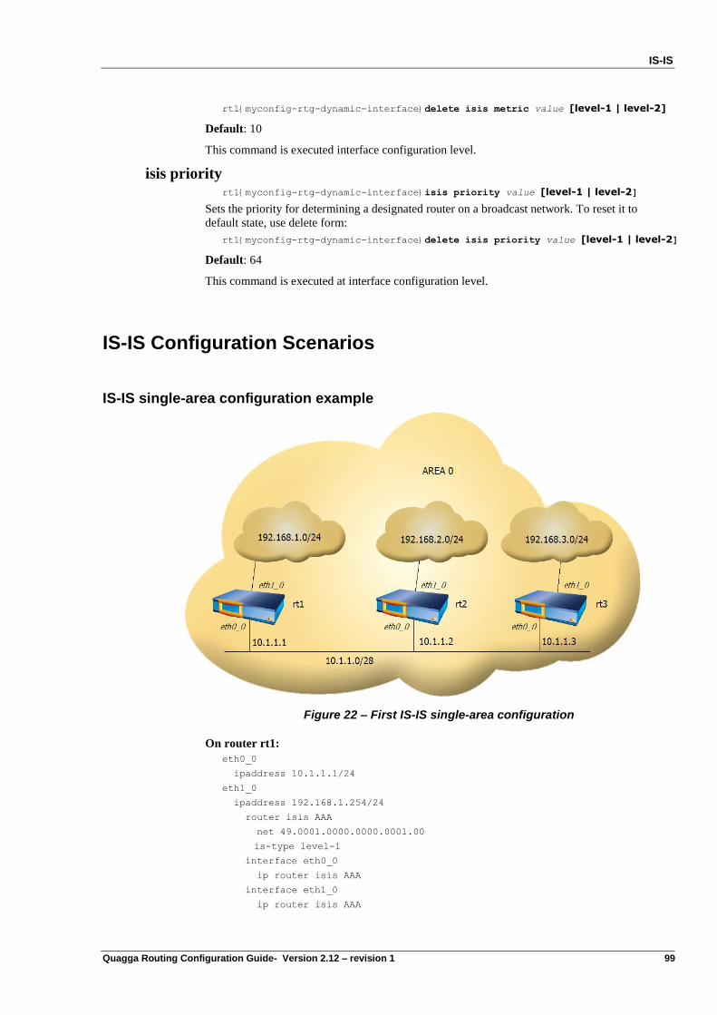
IS-IS
Quagga Routing Configuration Guide- Version 2.12 – revision 1 99
rt1{myconfig-rtg-dynamic-interface}delete isis metric value [level-1 | level-2]
Default: 10
This command is executed interface configuration level.
isis priority rt1{myconfig-rtg-dynamic-interface}isis priority value [level-1 | level-2]
Sets the priority for determining a designated router on a broadcast network. To reset it to
default state, use delete form:
rt1{myconfig-rtg-dynamic-interface}delete isis priority value [level-1 | level-2]
Default: 64
This command is executed at interface configuration level.
IS-IS Configuration Scenarios
IS-IS single-area configuration example
Figure 22 – First IS-IS single-area configuration
On router rt1:
eth0_0
ipaddress 10.1.1.1/24
eth1_0
ipaddress 192.168.1.254/24
router isis AAA
net 49.0001.0000.0000.0001.00
is-type level-1
interface eth0_0
ip router isis AAA
interface eth1_0
ip router isis AAA
IS-IS
100 Quagga Routing Configuration Guide- Version 2.12 – revision 1
On router rt2:
eth0_0
ipaddress 10.1.1.2/24
eth1_0
ipaddress 192.168.2.254/24
router isis AAA
net 49.0001.0000.0000.0002.00
is-type level-1
interface eth0_0
ip router isis AAA
interface eth1_0
ip router isis AAA
On router rt3:
eth0_0
ipaddress 10.1.1.3/24
eth1_0
ipaddress 192.168.3.254/24
router isis AAA
net 49.0001.0000.0000.0003.00
is-type level-1
interface eth0_0
ip router isis AAA
interface eth1_0
ip router isis AAA
Verifying operation
rt1{show-route}show isis neighbor
Area AAA:
System Id Interface L State Holdtime SNPA
49.0001.0000.0000.0001 eth0_0 1 Up 26 0008.a185.00e4
49.0001.0000.0000.0002 eth0_0 1 Up 28 0010.b5bd.e8e8
49.0001.0000.0000.0003 eth0_0 1 Up 26 0028.a154.010e
Please note that the state must be Up. In this state, routers are adjacent with each other and
exchange LSPs.
IS-IS database can be dumped with the following command. The details about these entries are
out of the scope of this document.
rt2{show-route}show isis database
Area AAA:
IS-IS Level-1 link-state database:
LSP ID LSP Seq Num LSP Checksum LSP Holdtime ATT/P/OL Tag
0001.0000.0001.00-00 >* 0x000014f1 0x2fcf 1143 0/0/0
0000.0000.0002.00-00 >* 0x0000a407 0x2fdb 1003 0/0/0
0000.0000.0003.00-00 >* 0x000014eb 0x2aef 967 0/0/0
0000.0000.0003.02-00 >* 0x0000110a 0x2f11 1107 0/0/0
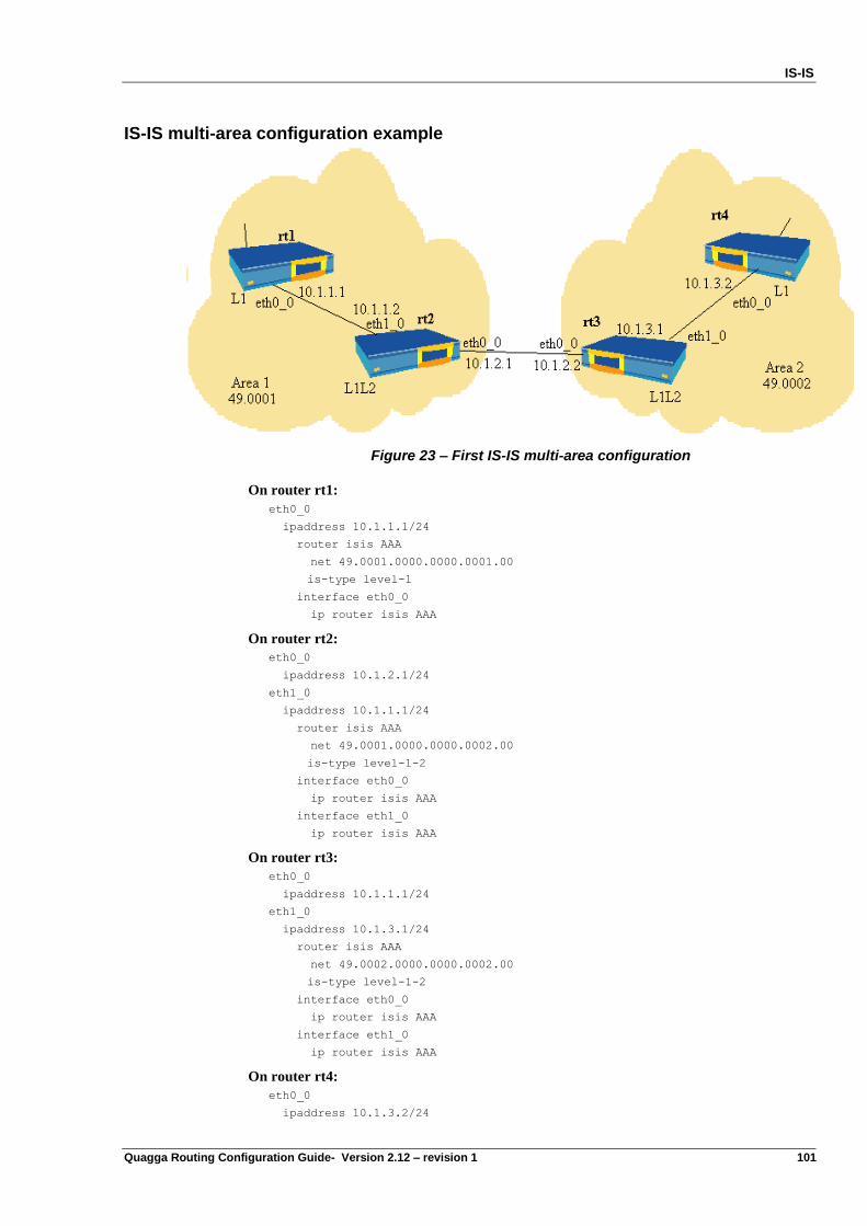
IS-IS
Quagga Routing Configuration Guide- Version 2.12 – revision 1 101
IS-IS multi-area configuration example
Figure 23 – First IS-IS multi-area configuration
On router rt1:
eth0_0
ipaddress 10.1.1.1/24
router isis AAA
net 49.0001.0000.0000.0001.00
is-type level-1
interface eth0_0
ip router isis AAA
On router rt2:
eth0_0
ipaddress 10.1.2.1/24
eth1_0
ipaddress 10.1.1.1/24
router isis AAA
net 49.0001.0000.0000.0002.00
is-type level-1-2
interface eth0_0
ip router isis AAA
interface eth1_0
ip router isis AAA
On router rt3:
eth0_0
ipaddress 10.1.1.1/24
eth1_0
ipaddress 10.1.3.1/24
router isis AAA
net 49.0002.0000.0000.0002.00
is-type level-1-2
interface eth0_0
ip router isis AAA
interface eth1_0
ip router isis AAA
On router rt4:
eth0_0
ipaddress 10.1.3.2/24
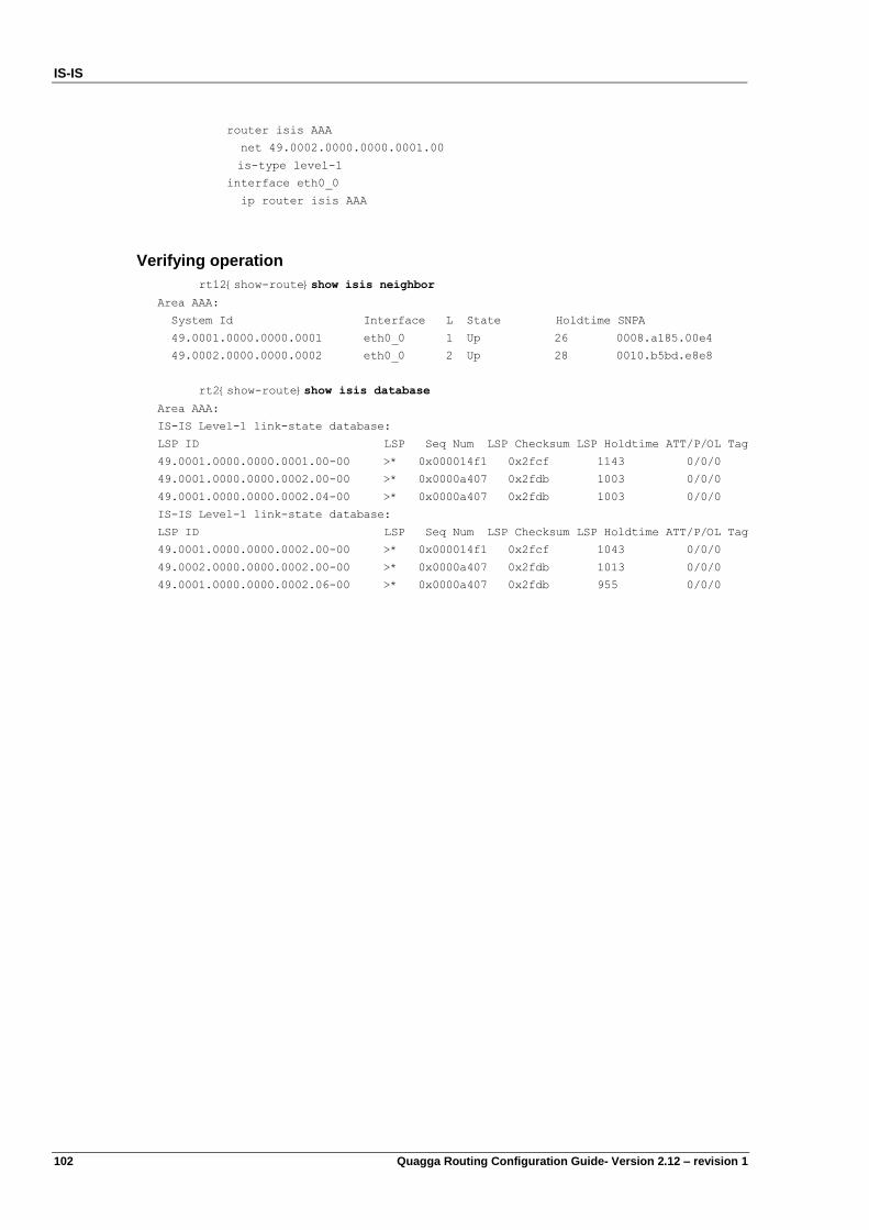
IS-IS
102 Quagga Routing Configuration Guide- Version 2.12 – revision 1
router isis AAA
net 49.0002.0000.0000.0001.00
is-type level-1
interface eth0_0
ip router isis AAA
Verifying operation
rt12{show-route}show isis neighbor
Area AAA:
System Id Interface L State Holdtime SNPA
49.0001.0000.0000.0001 eth0_0 1 Up 26 0008.a185.00e4
49.0002.0000.0000.0002 eth0_0 2 Up 28 0010.b5bd.e8e8
rt2{show-route}show isis database
Area AAA:
IS-IS Level-1 link-state database:
LSP ID LSP Seq Num LSP Checksum LSP Holdtime ATT/P/OL Tag
49.0001.0000.0000.0001.00-00 >* 0x000014f1 0x2fcf 1143 0/0/0
49.0001.0000.0000.0002.00-00 >* 0x0000a407 0x2fdb 1003 0/0/0
49.0001.0000.0000.0002.04-00 >* 0x0000a407 0x2fdb 1003 0/0/0
IS-IS Level-1 link-state database:
LSP ID LSP Seq Num LSP Checksum LSP Holdtime ATT/P/OL Tag
49.0001.0000.0000.0002.00-00 >* 0x000014f1 0x2fcf 1043 0/0/0
49.0002.0000.0000.0002.00-00 >* 0x0000a407 0x2fdb 1013 0/0/0
49.0001.0000.0000.0002.06-00 >* 0x0000a407 0x2fdb 955 0/0/0
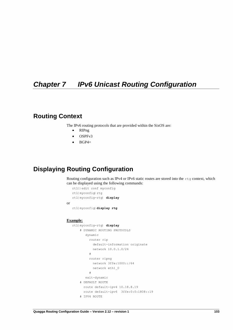
Quagga Routing Configuration Guide – Version 2.12 – revision 1 103
Chapter 7 IPv6 Unicast Routing Configuration
Routing Context
The IPv6 routing protocols that are provided within the SixOS are:
RIPng
OSPFv3
BGP4+
Displaying Routing Configuration
Routing configuration such as IPv4 or IPv6 static routes are stored into the rtg context, which
can be displayed using the following commands:
rt1{}edit conf myconfig
rt1{myconfig}rtg
rt1{myconfig-rtg} display
or
rt1{myconfig}display rtg
Example:
rt1{myconfig-rtg} display
# DYNAMIC ROUTING PROTOCOLS
dynamic
router rip
default-information originate
network 10.0.1.0/24
#
router ripng
network 3ffe:1000::/64
network eth1_0
#
exit-dynamic
# DEFAULT ROUTE
route default-ipv4 10.18.8.19
route default-ipv6 3ffe:0:0:1808::19
# IPV4 ROUTE
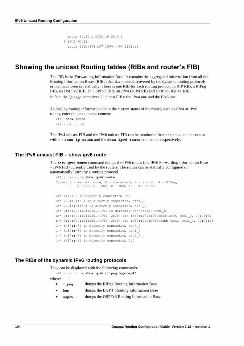
IPv6 Unicast Routing Configuration
104 Quagga Routing Configuration Guide- Version 2.12 – revision 1
route 10.20.1.0/24 10.20.0.1
# IPV6 ROUTE
route 3ffe:304:107:1800::/64 1111::2
Showing the unicast Routing tables (RIBs and router’s FIB)
The FIB is the Forwarding Information Base. It contains the aggregated information from all the
Routing Information Bases (RIBs) that have been discovered by the dynamic routing protocols
or that have been set statically. There is one RIB for each routing protocol: a RIP RIB, a RIPng
RIB, an OSPFv2 RIB, an OSPFv3 RIB, an IPv4 BGP4 RIB and an IPv6 BGP4+ RIB.
In fact, the Quagga comprizes 2 unicast FIBs: the IPv4 one and the IPv6 one.
To display routing information about the current status of the router, such as IPv4 or IPv6
routes, enter the show-route context:
rt1{}show route
rt1{show-route}
The IPv4 unicast FIB and the IPv6 unicast FIB can be monitored from the show-route context
with the show ip route and the show ipv6 route commands respectively.
The IPv6 unicast FIB – show ipv6 route
The show ipv6 route command dumps the IPv6 routes (the IPv6 Forwarding Information Base
– IPv6 FIB) currently used by the routers. The routes can be statically configured or
automatically learnt by a routing protocol.
rt1{show-route}show ipv6 route
Codes: K - kernel route, C - connected, S - static, R - RIPng,
O – OSPFv3, B - BGP, D – DEP, * - FIB route.
C>* ::1/128 is directly connected, lo0
C>* 2001:8::/64 is directly connected, eth1_0
C>* 2001:12::/64 is directly connected, eth2_0
C>* 3ffe:304:124:5101::/64 is directly connected, eth0_0
B>* 3ffe:304:124:5201::/64 [20/0] via fe80::250:4ff:fe53:1e49, eth1_0, 00:05:51
B>* 3ffe:304:124:5301::/64 [20/0] via fe80::2d0:b7ff:febb:4a42, eth2_0, 00:05:45
C * fe80::/64 is directly connected, eth2_0
C * fe80::/64 is directly connected, eth1_0
C * fe80::/64 is directly connected, eth0_0
C>* fe80::/64 is directly connected, lo0
The RIBs of the dynamic IPv6 routing protocols
They can be displayed with the following commands:
rt1{show-route}show ipv6 {ripng|bgp|ospf6}
where:
ripng dumps the RIPng Routing Information Base
bgp dumps the BGP4+Routing Information Base
ospf6 dumps the OSPFv3 Routing Information Base
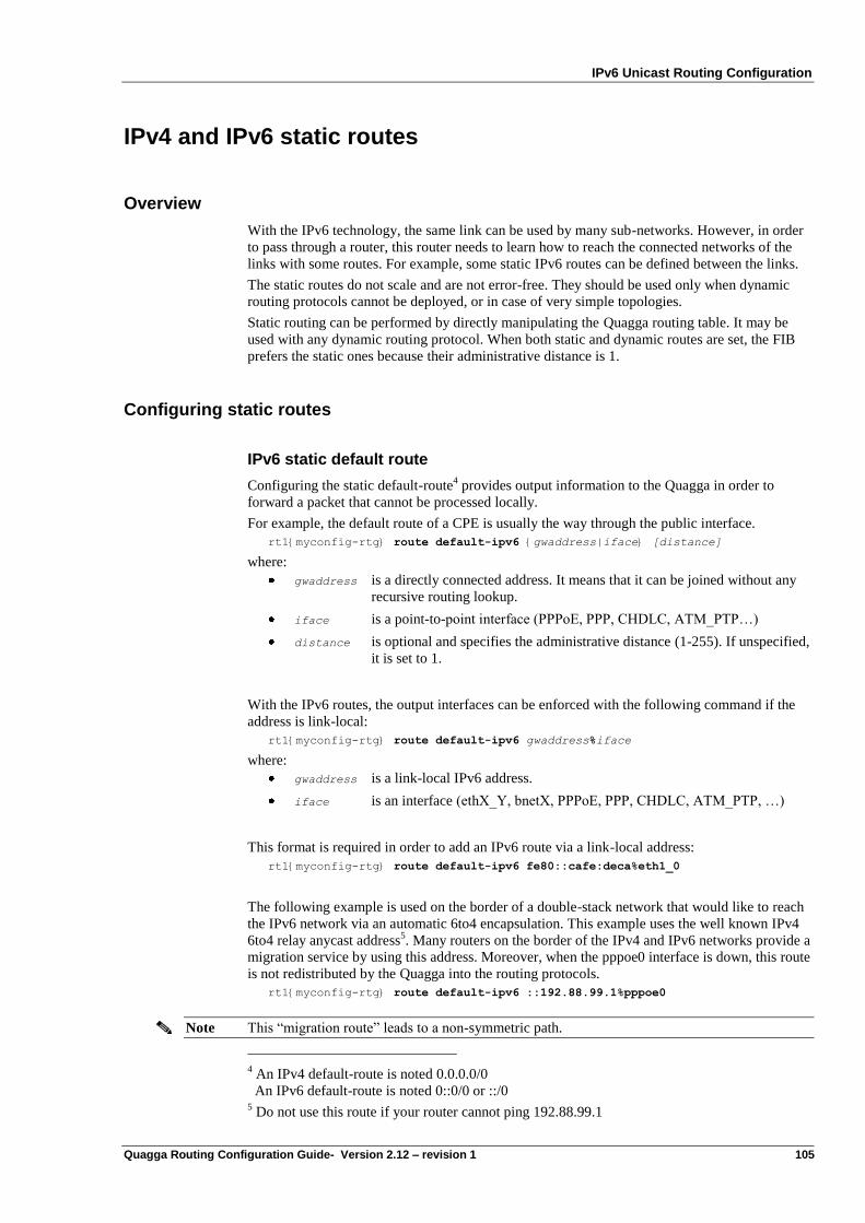
IPv6 Unicast Routing Configuration
Quagga Routing Configuration Guide- Version 2.12 – revision 1 105
IPv4 and IPv6 static routes
Overview
With the IPv6 technology, the same link can be used by many sub-networks. However, in order
to pass through a router, this router needs to learn how to reach the connected networks of the
links with some routes. For example, some static IPv6 routes can be defined between the links.
The static routes do not scale and are not error-free. They should be used only when dynamic
routing protocols cannot be deployed, or in case of very simple topologies.
Static routing can be performed by directly manipulating the Quagga routing table. It may be
used with any dynamic routing protocol. When both static and dynamic routes are set, the FIB
prefers the static ones because their administrative distance is 1.
Configuring static routes
IPv6 static default route
Configuring the static default-route4 provides output information to the Quagga in order to
forward a packet that cannot be processed locally.
For example, the default route of a CPE is usually the way through the public interface.
rt1{myconfig-rtg} route default-ipv6 {gwaddress|iface} [distance]
where:
gwaddress is a directly connected address. It means that it can be joined without any
recursive routing lookup.
iface is a point-to-point interface (PPPoE, PPP, CHDLC, ATM_PTP…)
distance is optional and specifies the administrative distance (1-255). If unspecified,
it is set to 1.
With the IPv6 routes, the output interfaces can be enforced with the following command if the
address is link-local:
rt1{myconfig-rtg} route default-ipv6 gwaddress%iface
where:
gwaddress is a link-local IPv6 address.
iface is an interface (ethX_Y, bnetX, PPPoE, PPP, CHDLC, ATM_PTP, …)
This format is required in order to add an IPv6 route via a link-local address:
rt1{myconfig-rtg} route default-ipv6 fe80::cafe:deca%eth1_0
The following example is used on the border of a double-stack network that would like to reach
the IPv6 network via an automatic 6to4 encapsulation. This example uses the well known IPv4
6to4 relay anycast address5. Many routers on the border of the IPv4 and IPv6 networks provide a
migration service by using this address. Moreover, when the pppoe0 interface is down, this route
is not redistributed by the Quagga into the routing protocols.
rt1{myconfig-rtg} route default-ipv6 ::192.88.99.1%pppoe0
Note This “migration route” leads to a non-symmetric path.
4 An IPv4 default-route is noted 0.0.0.0/0
An IPv6 default-route is noted 0::0/0 or ::/0 5 Do not use this route if your router cannot ping 192.88.99.1
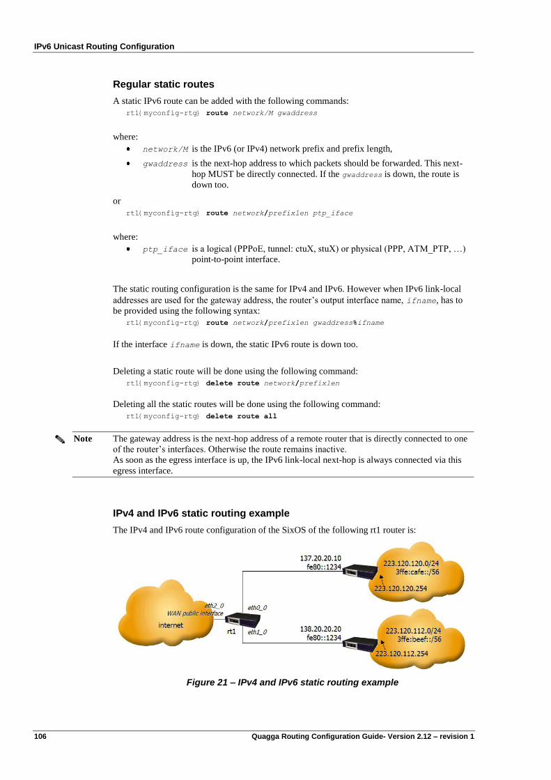
IPv6 Unicast Routing Configuration
106 Quagga Routing Configuration Guide- Version 2.12 – revision 1
Regular static routes
A static IPv6 route can be added with the following commands:
rt1{myconfig-rtg} route network/M gwaddress
where:
network/M is the IPv6 (or IPv4) network prefix and prefix length,
gwaddress is the next-hop address to which packets should be forwarded. This next-
hop MUST be directly connected. If the gwaddress is down, the route is
down too.
or
rt1{myconfig-rtg} route network/prefixlen ptp_iface
where:
ptp_iface is a logical (PPPoE, tunnel: ctuX, stuX) or physical (PPP, ATM_PTP, …)
point-to-point interface.
The static routing configuration is the same for IPv4 and IPv6. However when IPv6 link-local
addresses are used for the gateway address, the router‟s output interface name, ifname, has to
be provided using the following syntax:
rt1{myconfig-rtg} route network/prefixlen gwaddress%ifname
If the interface ifname is down, the static IPv6 route is down too.
Deleting a static route will be done using the following command:
rt1{myconfig-rtg} delete route network/prefixlen
Deleting all the static routes will be done using the following command:
rt1{myconfig-rtg} delete route all
Note The gateway address is the next-hop address of a remote router that is directly connected to one
of the router‟s interfaces. Otherwise the route remains inactive.
As soon as the egress interface is up, the IPv6 link-local next-hop is always connected via this
egress interface.
IPv4 and IPv6 static routing example
The IPv4 and IPv6 route configuration of the SixOS of the following rt1 router is:
Figure 21 – IPv4 and IPv6 static routing example
IPv6 Unicast Routing Configuration
Quagga Routing Configuration Guide- Version 2.12 – revision 1 107
rt1{myconfig-rtg} route 223.120.120.0/24 137.20.20.10
rt1{myconfig-rtg} route 223.120.112.0/24 138.20.20.20
These two previous commands indicate that the network 223.120.120.0/24 (resp.
223.120.112.0/24) is reached via the next hop whose IPv4 address is 137.20.20.10 (resp.
138.20.20.20) that is connected to the subnet reachable via the eth0_0 (resp. eth1_0) interface.
However, the following configuration would not work because the next-hops are not directly
connected:
rt1{myconfig-rtg} route 223.120.120.0/24 223.120.120.254
rt1{myconfig-rtg} route 223.120.112.0/24 223.120.112.254
The following command deletes the specified route:
rt1{myconfig-rtg} delete route 223.120.120.0/24
The scope of the gateway addresses fe80::1234%eth0_0 and fe80::1234%eth1_0 is local.
rt1{myconfig-rtg} route 3ffe:cafe::/56 fe80::1234%eth0_0
rt1{myconfig-rtg} route 3ffe:beef::/56 fe80::1234%eth1_0
The following command deletes the specified route:
rt1{myconfig-rtg} delete route 3ffe:cafe::/56
ECMP
Like in IPv4, Equal Cost Multi Path (ECMP) is supported. This feature allows defining several
paths which have the same cost. It is mainly used for load balancing.
It is assumed the Operating System has been compiled with the appropriate enable-multipath
option.

Quagga Routing Configuration Guide – Version 2.12 – revision 1 109
Chapter 8 RIPng
Configuring RIPng
RIPng works the same way as RIP and offers the same advantages. The RIPng protocol uses the
Bellman-Ford algorithm, and as RIP the network diameter is limited to 15 hops. The detailed
specification of the protocol is described in the RFC 2080.
RIPng Configuration Steps:
2 steps are required to configure RIPng
Step 1: Start/Stop RIPng
RIP is started when the dynamic RIPng context is created with the following command into the
dynamic routing context:
rt3{myconfig-rtg-dynamic}router ripng
Step 2: Activate RIPng
Within the dynamic RIPng context, RIPng has to be activated on the interfaces that are
connected to a RIPng enabled network. In order to activate RIPng, either the name of the
interface (e.g. eth1_0) or the network prefix (e.g. 2001::/16) can be provided. Thus, the prefixes
of the interface or the ones that are included into the network prefix are announced.
rt3{myconfig-rtg-dynamic-router-ripng}network eth1_0
or
rt3{myconfig-rtg-dynamic-router-ripng}network 2001::/16
Note These prefixes that are announced with the network command are named Connected-interface
(C(i)).
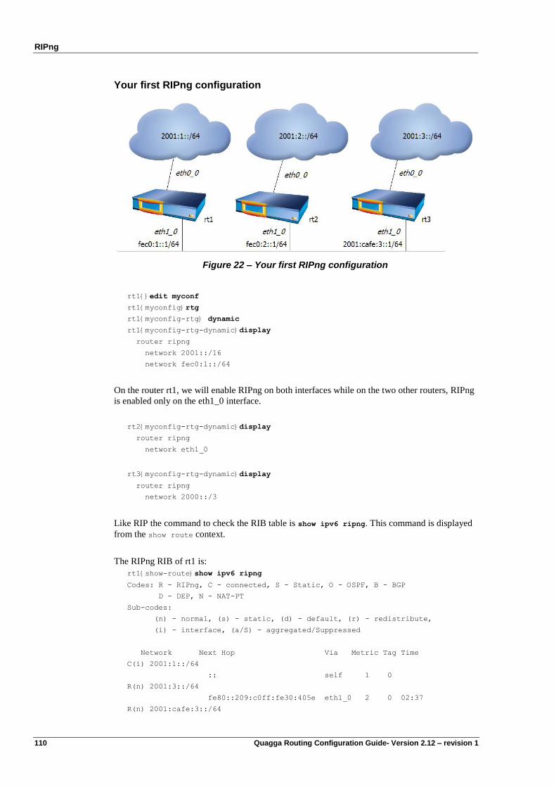
RIPng
110 Quagga Routing Configuration Guide- Version 2.12 – revision 1
Your first RIPng configuration
Figure 22 – Your first RIPng configuration
rt1{}edit myconf
rt1{myconfig}rtg
rt1{myconfig-rtg} dynamic
rt1{myconfig-rtg-dynamic}display
router ripng
network 2001::/16
network fec0:1::/64
On the router rt1, we will enable RIPng on both interfaces while on the two other routers, RIPng
is enabled only on the eth1_0 interface.
rt2{myconfig-rtg-dynamic}display
router ripng
network eth1_0
rt3{myconfig-rtg-dynamic}display
router ripng
network 2000::/3
Like RIP the command to check the RIB table is show ipv6 ripng. This command is displayed
from the show route context.
The RIPng RIB of rt1 is:
rt1{show-route}show ipv6 ripng
Codes: R - RIPng, C - connected, S - Static, O - OSPF, B - BGP
D - DEP, N - NAT-PT
Sub-codes:
(n) - normal, (s) - static, (d) - default, (r) - redistribute,
(i) - interface, (a/S) - aggregated/Suppressed
Network Next Hop Via Metric Tag Time
C(i) 2001:1::/64
:: self 1 0
R(n) 2001:3::/64
fe80::209:c0ff:fe30:405e eth1_0 2 0 02:37
R(n) 2001:cafe:3::/64
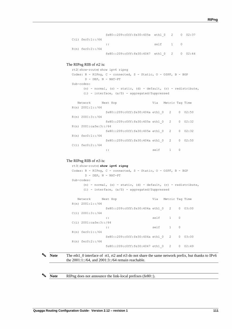
RIPng
Quagga Routing Configuration Guide- Version 2.12 – revision 1 111
fe80::209:c0ff:fe30:405e eth1_0 2 0 02:37
C(i) fec0:1::/64
:: self 1 0
R(n) fec0:2::/64
fe80::209:c0ff:fe30:4047 eth1_0 2 0 02:44
The RIPng RIB of rt2 is:
rt2{show-route}show ipv6 ripng
Codes: R - RIPng, C - connected, S - Static, O - OSPF, B - BGP
D - DEP, N - NAT-PT
Sub-codes:
(n) - normal, (s) - static, (d) - default, (r) - redistribute,
(i) - interface, (a/S) - aggregated/Suppressed
Network Next Hop Via Metric Tag Time
R(n) 2001:1::/64
fe80::209:c0ff:fe30:404a eth1_0 2 0 02:50
R(n) 2001:3::/64
fe80::209:c0ff:fe30:405e eth1_0 2 0 02:32
R(n) 2001:cafe:3::/64
fe80::209:c0ff:fe30:405e eth1_0 2 0 02:32
R(n) fec0:1::/64
fe80::209:c0ff:fe30:404a eth1_0 2 0 02:50
C(i) fec0:2::/64
:: self 1 0
The RIPng RIB of rt3 is:
rt3{show-route}show ipv6 ripng
Codes: R - RIPng, C - connected, S - Static, O - OSPF, B - BGP
D - DEP, N - NAT-PT
Sub-codes:
(n) - normal, (s) - static, (d) - default, (r) - redistribute,
(i) - interface, (a/S) - aggregated/Suppressed
Network Next Hop Via Metric Tag Time
R(n) 2001:1::/64
fe80::209:c0ff:fe30:404a eth1_0 2 0 03:00
C(i) 2001:3::/64
:: self 1 0
C(i) 2001:cafe:3::/64
:: self 1 0
R(n) fec0:1::/64
fe80::209:c0ff:fe30:404a eth1_0 2 0 03:00
R(n) fec0:2::/64
fe80::209:c0ff:fe30:4047 eth1_0 2 0 02:49
Note The eth1_0 interface of rt1, rt2 and rt3 do not share the same network prefix, but thanks to IPv6
the 2001:1::/64, and 2001:3::/64 remain reachable.
Note RIPng does not announce the link-local prefixes (fe80::).
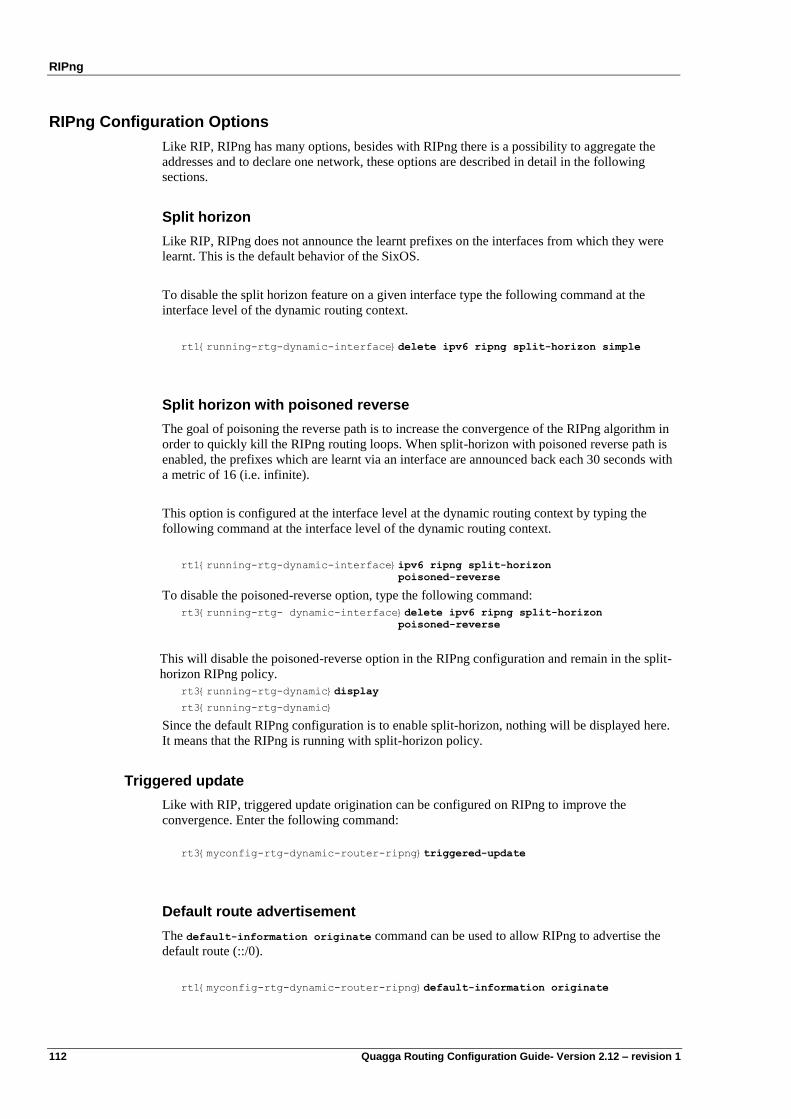
RIPng
112 Quagga Routing Configuration Guide- Version 2.12 – revision 1
RIPng Configuration Options
Like RIP, RIPng has many options, besides with RIPng there is a possibility to aggregate the
addresses and to declare one network, these options are described in detail in the following
sections.
Split horizon
Like RIP, RIPng does not announce the learnt prefixes on the interfaces from which they were
learnt. This is the default behavior of the SixOS.
To disable the split horizon feature on a given interface type the following command at the
interface level of the dynamic routing context.
rt1{running-rtg-dynamic-interface}delete ipv6 ripng split-horizon simple
Split horizon with poisoned reverse
The goal of poisoning the reverse path is to increase the convergence of the RIPng algorithm in
order to quickly kill the RIPng routing loops. When split-horizon with poisoned reverse path is
enabled, the prefixes which are learnt via an interface are announced back each 30 seconds with
a metric of 16 (i.e. infinite).
This option is configured at the interface level at the dynamic routing context by typing the
following command at the interface level of the dynamic routing context.
rt1{running-rtg-dynamic-interface}ipv6 ripng split-horizon
poisoned-reverse
To disable the poisoned-reverse option, type the following command:
rt3{running-rtg- dynamic-interface}delete ipv6 ripng split-horizon
poisoned-reverse
This will disable the poisoned-reverse option in the RIPng configuration and remain in the split-
horizon RIPng policy.
rt3{running-rtg-dynamic}display
rt3{running-rtg-dynamic}
Since the default RIPng configuration is to enable split-horizon, nothing will be displayed here.
It means that the RIPng is running with split-horizon policy.
Triggered update
Like with RIP, triggered update origination can be configured on RIPng to improve the
convergence. Enter the following command:
rt3{myconfig-rtg-dynamic-router-ripng}triggered-update
Default route advertisement
The default-information originate command can be used to allow RIPng to advertise the
default route (::/0).
rt1{myconfig-rtg-dynamic-router-ripng}default-information originate
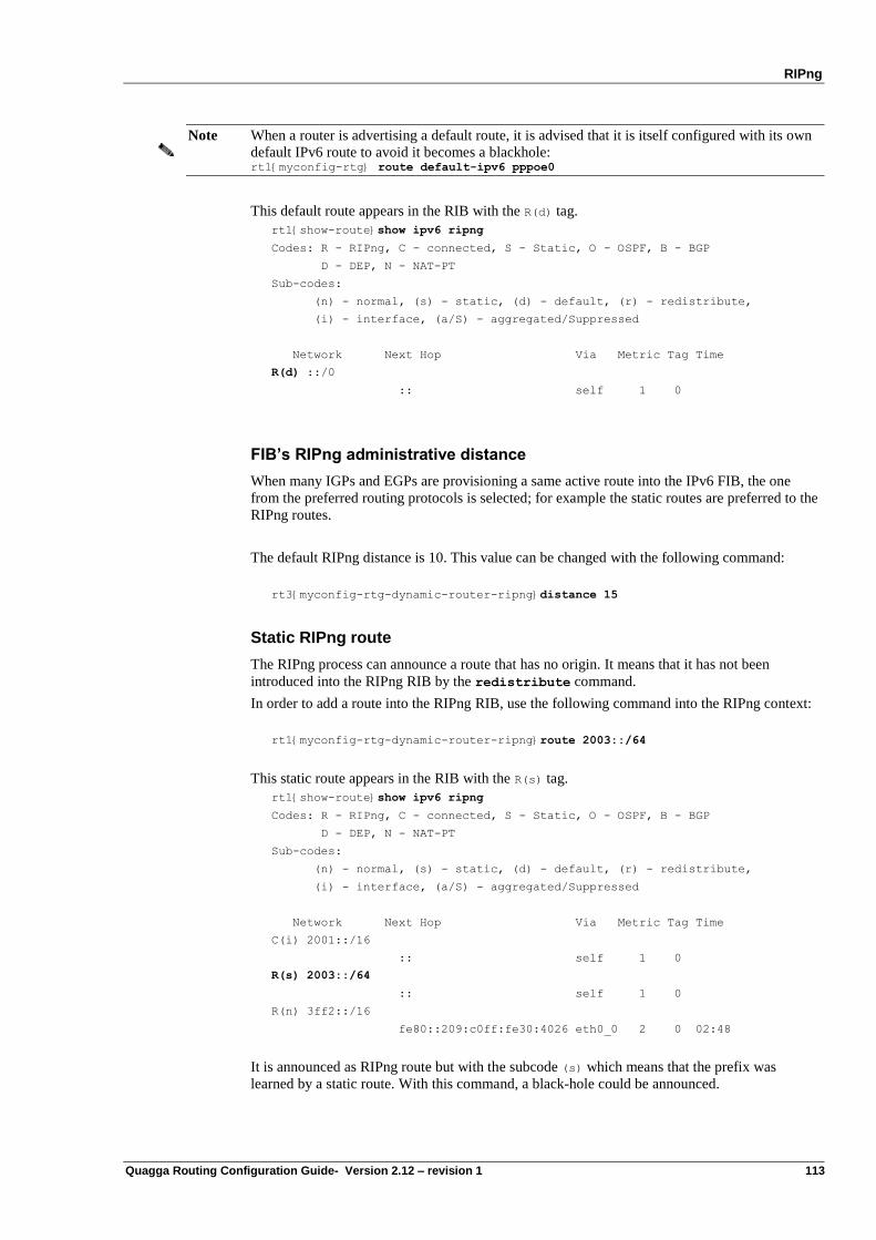
RIPng
Quagga Routing Configuration Guide- Version 2.12 – revision 1 113
Note When a router is advertising a default route, it is advised that it is itself configured with its own
default IPv6 route to avoid it becomes a blackhole: rt1{myconfig-rtg} route default-ipv6 pppoe0
This default route appears in the RIB with the R(d) tag.
rt1{show-route}show ipv6 ripng
Codes: R - RIPng, C - connected, S - Static, O - OSPF, B - BGP
D - DEP, N - NAT-PT
Sub-codes:
(n) - normal, (s) - static, (d) - default, (r) - redistribute,
(i) - interface, (a/S) - aggregated/Suppressed
Network Next Hop Via Metric Tag Time
R(d) ::/0
:: self 1 0
FIB’s RIPng administrative distance
When many IGPs and EGPs are provisioning a same active route into the IPv6 FIB, the one
from the preferred routing protocols is selected; for example the static routes are preferred to the
RIPng routes.
The default RIPng distance is 10. This value can be changed with the following command:
rt3{myconfig-rtg-dynamic-router-ripng}distance 15
Static RIPng route
The RIPng process can announce a route that has no origin. It means that it has not been
introduced into the RIPng RIB by the redistribute command.
In order to add a route into the RIPng RIB, use the following command into the RIPng context:
rt1{myconfig-rtg-dynamic-router-ripng}route 2003::/64
This static route appears in the RIB with the R(s) tag.
rt1{show-route}show ipv6 ripng
Codes: R - RIPng, C - connected, S - Static, O - OSPF, B - BGP
D - DEP, N - NAT-PT
Sub-codes:
(n) - normal, (s) - static, (d) - default, (r) - redistribute,
(i) - interface, (a/S) - aggregated/Suppressed
Network Next Hop Via Metric Tag Time
C(i) 2001::/16
:: self 1 0
R(s) 2003::/64
:: self 1 0
R(n) 3ff2::/16
fe80::209:c0ff:fe30:4026 eth0_0 2 0 02:48
It is announced as RIPng route but with the subcode (s) which means that the prefix was
learned by a static route. With this command, a black-hole could be announced.
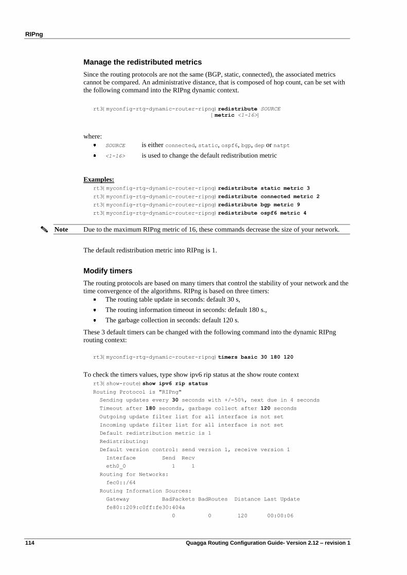
RIPng
114 Quagga Routing Configuration Guide- Version 2.12 – revision 1
Manage the redistributed metrics
Since the routing protocols are not the same (BGP, static, connected), the associated metrics
cannot be compared. An administrative distance, that is composed of hop count, can be set with
the following command into the RIPng dynamic context.
rt3{myconfig-rtg-dynamic-router-ripng}redistribute SOURCE
[metric <1-16>]
where:
SOURCE is either connected, static, ospf6, bgp, dep or natpt
<1-16> is used to change the default redistribution metric
Examples:
rt3{myconfig-rtg-dynamic-router-ripng}redistribute static metric 3
rt3{myconfig-rtg-dynamic-router-ripng}redistribute connected metric 2
rt3{myconfig-rtg-dynamic-router-ripng}redistribute bgp metric 9
rt3{myconfig-rtg-dynamic-router-ripng}redistribute ospf6 metric 4
Note Due to the maximum RIPng metric of 16, these commands decrease the size of your network.
The default redistribution metric into RIPng is 1.
Modify timers
The routing protocols are based on many timers that control the stability of your network and the
time convergence of the algorithms. RIPng is based on three timers:
The routing table update in seconds: default 30 s,
The routing information timeout in seconds: default 180 s.,
The garbage collection in seconds: default 120 s.
These 3 default timers can be changed with the following command into the dynamic RIPng
routing context:
rt3{myconfig-rtg-dynamic-router-ripng}timers basic 30 180 120
To check the timers values, type show ipv6 rip status at the show route context
rt3{show-route}show ipv6 rip status
Routing Protocol is "RIPng"
Sending updates every 30 seconds with +/-50%, next due in 4 seconds
Timeout after 180 seconds, garbage collect after 120 seconds
Outgoing update filter list for all interface is not set
Incoming update filter list for all interface is not set
Default redistribution metric is 1
Redistributing:
Default version control: send version 1, receive version 1
Interface Send Recv
eth0_0 1 1
Routing for Networks:
fec0::/64
Routing Information Sources:
Gateway BadPackets BadRoutes Distance Last Update
fe80::209:c0ff:fe30:404a
0 0 120 00:00:06
RIPng
Quagga Routing Configuration Guide- Version 2.12 – revision 1 115
fe80::209:c0ff:fe30:4046
0 0 120 00:00:24
Note Do not change any default value if you are deploying a RIPng network over a Local Area
Network (LAN). They might be changed only over some very low bandwidth links (about 32
Kbit/s or less) or over the cost expensive links.
Route aggregation
The routes redistributed by RIPng can be aggregated in order to decrease the FIB table or to hide
the internal architecture of your network. This aggregation can be done with the following
command:
rt1{myconfig-rtg-dynamic-router-ripng}aggregate-address X:X::X:X/M
where:
X:X::X:X/M is the only network prefix that should be announced by RIPng.
Please note that this feature is specific to RIPng and is not available with RIP.
For example:
router ripng
aggregate-address 3ffe:501:ffff:4000::/52
network 3ffe:501:ffff::/48
eth0_0
ipaddress 3ffe:501:ffff:4001::4/64
eth1_0
ipaddress 3ffe:501:ffff:4000::4/64
eth2_0
ipaddress 3ffe:501:ffff:1::4/64
It leads to the following RIPng RIB:
rt1{show-route}show ipv6 rip
Codes: R - RIPng, C - connected, S - Static, O - OSPF, B - BGP
D - DEP, N - NAT-PT
Sub-codes:
(n) - normal, (s) - static, (d) - default, (r) - redistribute,
(i) - interface, (a/S) - aggregated/Suppressed
Network Next Hop Via Metric Tag Time
C(i) 2001::/16
:: self 1 0
R(a) 3ffe:501:fff:4000::/52 self 1 0
C(i) 3ffe:501:ffff:4000::/64
:: self 1 0
C(i) 3ffe:501:ffff:4001::/64
:: self 1 0
C(i) fec0::/64
:: self 1 0
The tag R(a) means that the prefix 3ffe:501:ffff:4000::/52 is an aggregated one.
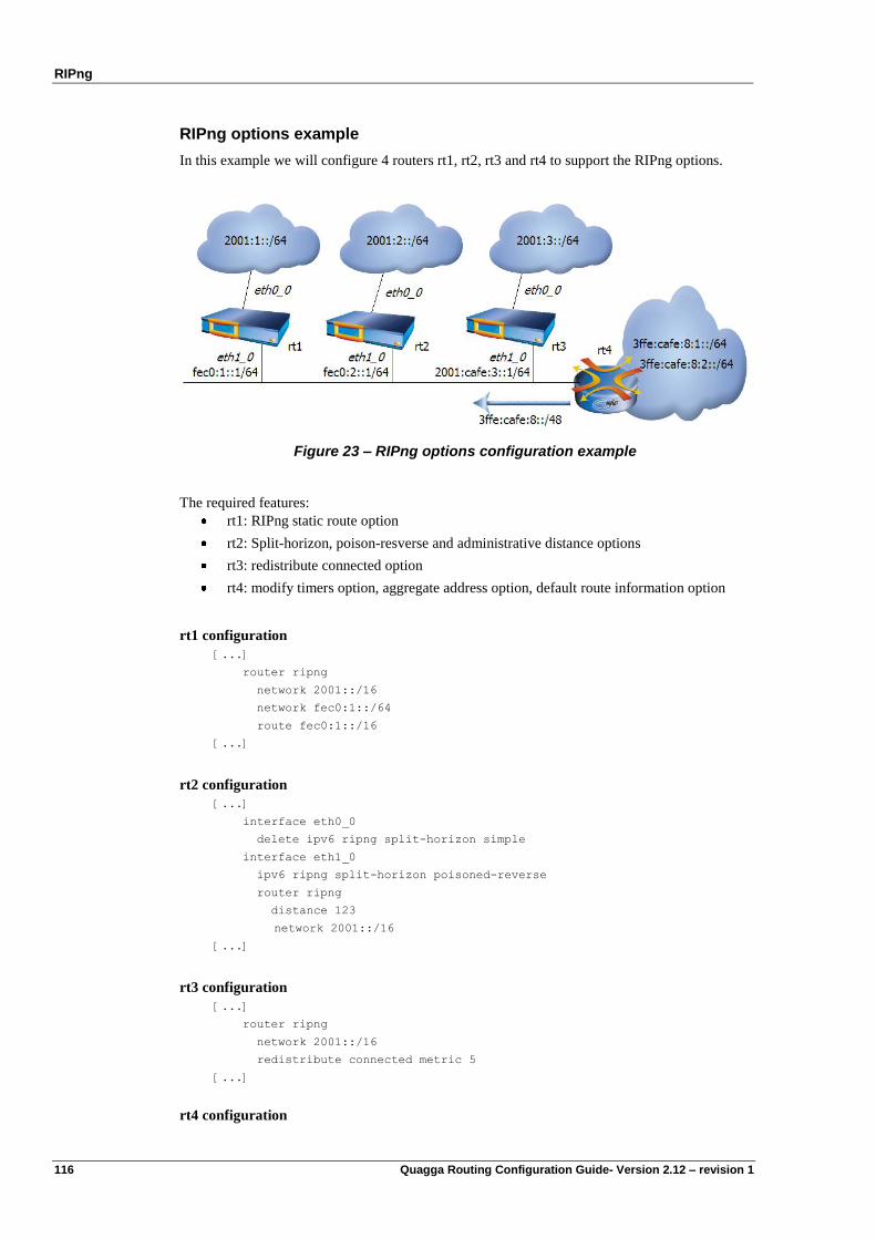
RIPng
116 Quagga Routing Configuration Guide- Version 2.12 – revision 1
RIPng options example
In this example we will configure 4 routers rt1, rt2, rt3 and rt4 to support the RIPng options.
Figure 23 – RIPng options configuration example
The required features:
rt1: RIPng static route option
rt2: Split-horizon, poison-resverse and administrative distance options
rt3: redistribute connected option
rt4: modify timers option, aggregate address option, default route information option
rt1 configuration
[...]
router ripng
network 2001::/16
network fec0:1::/64
route fec0:1::/16
[...]
rt2 configuration
[...]
interface eth0_0
delete ipv6 ripng split-horizon simple
interface eth1_0
ipv6 ripng split-horizon poisoned-reverse
router ripng
distance 123
network 2001::/16
[...]
rt3 configuration
[...]
router ripng
network 2001::/16
redistribute connected metric 5
[...]
rt4 configuration
RIPng
Quagga Routing Configuration Guide- Version 2.12 – revision 1 117
[...]
router ripng
aggregate-address 3ffe:cafe:8::/48
default-information originate
network 3ffe:cafe:8:1::/64
network 3ffe:cafe:8:2::/64
timers basic 30 180 90
[...]
ECMP
As shown for RIP in IPv4, RIPng protocol is compatible with Equal Cost Multi Path (ECMP)
which allows defining several paths that have the same cost.

Quagga Routing Configuration Guide – Version 2.12 – revision 1 119
Chapter 9 OSPFv3
OSPFv3 overview
OSPFv3 is a redesign of OSPFv2 which adds support for a generic address family. Up to now,
only the IPv6 address family has been defined. The OSPFv3 protocol is described in RFC 2740.
It inherits most of the OSPFv2 mechanisms (Flooding, DR, LSU,…) with little changes.
In OSPFv3, router-id has the same format as OSPFv2, new and modified LSAs have been
created to handle the flow of IPv6 addresses and prefixes in an OSPFv3 network. The new LSAs
introduced in OSPFv3 are the Link LSA, and the Intra-Area-Prefix LSA.
Configuring OSPFv3 in a single area
The configuration of OSPFv3 in a single area is similar to the configuration of OSPFv2, with
slight changes. To configure OSPFv3 follow these steps.
Step 1: Create the OSPFv3 context at the dynamic routing context
rt1{running-rtg-dynamic}router ospf6
Step 2: At ospf6 context assign your router an OSPF router-id
rt1{running-rtg-dynamic-router-ospf6}ospf6 router-id A.B.C.D
Where A.B.C.D is an IPv4 address of one of your router interfaces, or an arbitrarily chosen id. It
must match the form of an IPv4 address (i.e. a 32 bits number).
Step 3: Activate OSPF on the desired interfaces
OSPFv3 is designed as a per-interface protocol. It can start listening on the multicast group
with the following command:
rt1{running-rtg-dynamic-router-ospf6}interface ifacename area area-id
OSPFv3
120 Quagga Routing Configuration Guide- Version 2.12 – revision 1
Where:
ifacename is the name of the interface on which OSPF is active
area-id is the area id of the OSPF network to which the interface belongs,
the area-id is written in the form A.B.C.D
Note This command supports simple regular expressions for interface names: a star * stands for any
leading integer.
For instance, ctu* matches ctu0, ctu1 and ctu234, but not ctu_ppp0 or ctu.
If several interface commands overlap (e.g. ctu* and ctu2), they must specify the same
area-id, otherwise the result is undefined.
Verifying operation
Like with OSPFv2, use the show commands to verify operation:
rt1{show-route}show ipv6 ospf6
rt1{show-route}show ipv6 ospf6 interface
rt1{show-route}show ipv6 ospf6 neighbor [detail]
rt1{show-route}show ipv6 ospf6 route
rt1{show-route}show ipv6 ospf6 database
rt1{show-route}show ipv6 ospf6 database [param]
Where param is one of the following value:
detail LSAs details
dump Dump LSAs
internal Display LSA's internal information
as-external Display As-External LSAs
group-membership Display Group-Membership LSAs
inter-prefix Display Inter-Area-Prefix LSAs
inter-router Display Inter-Area-Router LSAs
intra-prefix Display Intra-Area-Prefix LSAs
link Display Link LSAs
network Display Network LSAs
router Display Router LSAs
type-7 Display Type-7 LSAs
* Any Link state Type
adv-router Search by Advertising Router
linkstate-id Search by Link state ID
self-originated Self-originated link states
All these commands are executed from the show-route context
Example of output and explanations is provided in the „configuration example‟.
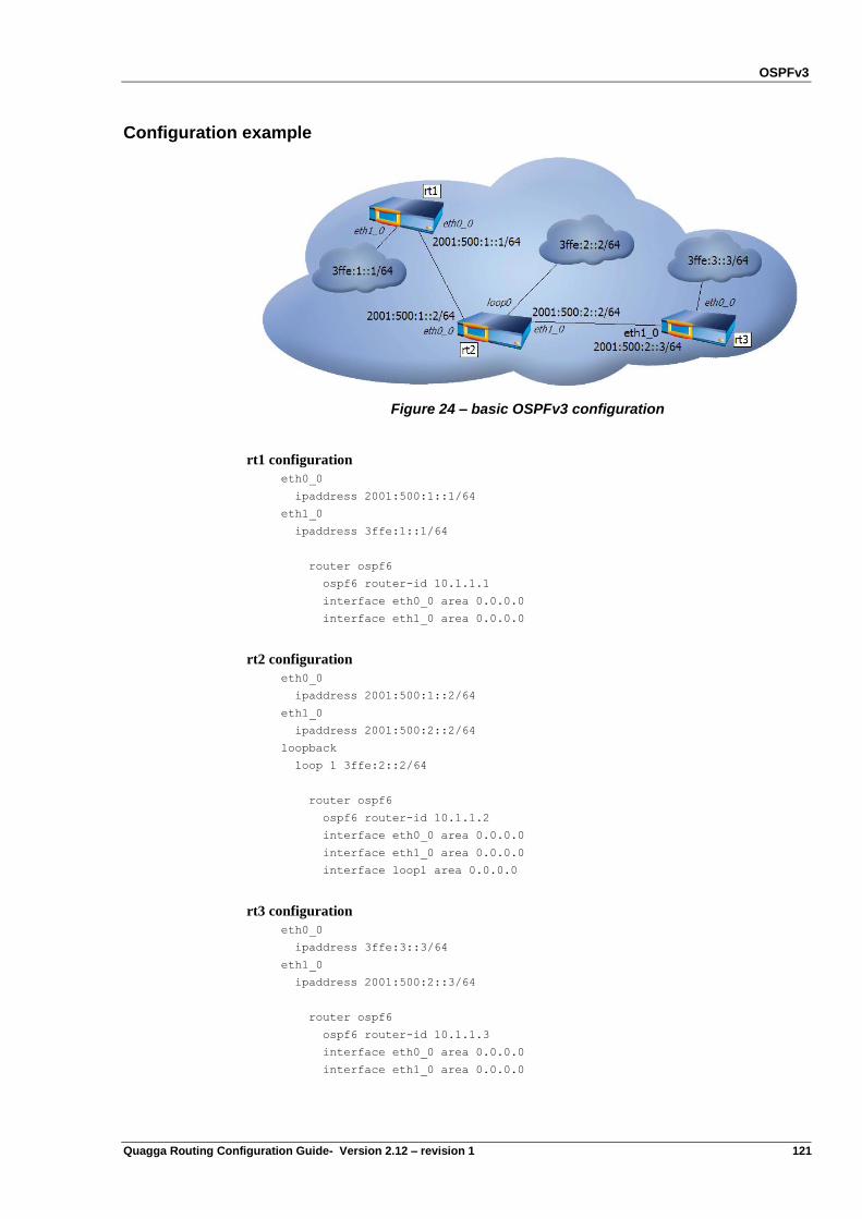
OSPFv3
Quagga Routing Configuration Guide- Version 2.12 – revision 1 121
Configuration example
Figure 24 – basic OSPFv3 configuration
rt1 configuration
eth0_0
ipaddress 2001:500:1::1/64
eth1_0
ipaddress 3ffe:1::1/64
router ospf6
ospf6 router-id 10.1.1.1
interface eth0_0 area 0.0.0.0
interface eth1_0 area 0.0.0.0
rt2 configuration
eth0_0
ipaddress 2001:500:1::2/64
eth1_0
ipaddress 2001:500:2::2/64
loopback
loop 1 3ffe:2::2/64
router ospf6
ospf6 router-id 10.1.1.2
interface eth0_0 area 0.0.0.0
interface eth1_0 area 0.0.0.0
interface loop1 area 0.0.0.0
rt3 configuration
eth0_0
ipaddress 3ffe:3::3/64
eth1_0
ipaddress 2001:500:2::3/64
router ospf6
ospf6 router-id 10.1.1.3
interface eth0_0 area 0.0.0.0
interface eth1_0 area 0.0.0.0
OSPFv3
122 Quagga Routing Configuration Guide- Version 2.12 – revision 1
As with OSPFv2, the most important commands to verify OSPFv3 operations are:
show ipv6 ospf6 neighbor
show ipv6 ospf6 database
show ipv6 ospf6 route
rt1{show-route}show ipv6 ospf6 neighbor
RouterID State/Duration DR BDR I/F[State]
10.1.1.2 Full/00:09:44 10.1.1.2 10.1.1.1 eth1_0[BDR]
Please note that the state must be at “Full”, otherwise it means that the OSPFv3 neighberhood is
not correctly formed.
rt1{show-route}show ipv6 ospf6 route
Destination Gateway I/F
---------------------------
*N Ia 2001:500:1::/64 fe80::209:c0ff:fe30:4047 eth1_0 00:16:56
*N Ia 2001:500:2::/64 :: eth1_0 00:17:01
N Ia 2001:500:2::/64 fe80::209:c0ff:fe30:4047 eth1_0 00:16:56
*N Ia 3ffe:1::/64 :: eth1_0 00:17:01
*N Ia 3ffe:2::/64 fe80::209:c0ff:fe30:4047 eth1_0 00:16:56
*N Ia 3ffe:3::/64 fe80::209:c0ff:fe30:4047 eth1_0 00:16:56
===========
Route: 5 Path: 6 Redundant: 1
OSPFv3 options
OSPFv3 cost
rt1{running-rtg-dynamic-interface}ipv6 ospf6 cost COST
This command, executed at the interface level of the Dynamic routing context, sets the interface
output cost. Default value is 1.
It is possible to calculate an OSPF interface cost according to the bandwidth available on the
corresponding link.
rt1{myconfig-rtg-dynamic-router-ospf6}auto-cost reference-bandwidth BW
Where:
BW is the reference bandwidth in terms of Mbits per second (1-4294967)
OSPFv3 priority
rt1{running-rtg-dynamic-interface}ipv6 ospf6 priority PRIORITY
Sets interface‟s Router Priority for election of designated router. Default value is 1.
This command is executed at the interface level of routing Dynamic context.
OSPFv3
Quagga Routing Configuration Guide- Version 2.12 – revision 1 123
OSPFv3 hello interval
rt1{running-rtg-dynamic-interface}ipv6 ospf6 hello-interval
INTERVAL
Sets interface Hello Interval. Default value is 40.
This command is executed at the interface level of routing Dynamic context.
OSPFv3 transmit-delay
rt1{running-rtg-dynamic-interface}ipv6 ospf6 transmit-delay DELAY
Sets interface Inf-Trans-Delay. Default value is 1.
This command is executed at the interface level of routing Dynamic context.
Default route advertisement
rt1{myconfig-rtg-dynamic-router-ospf6}default-information originate
This feature and its options are the same as for IPv4. The command default-information
originate can be used to allow OSPF to advertise the default route 0.0.0.0/0. It is used on
ASBR routers.
Passive interface
This feature should be used when you want to prevent some router's interfaces from forming
OSPF adjacencies. It may be for instance to include a subnet into the OSPF routing process (and
Link State Database), without actually running OSPF on the interface of the router connected to
that subnet. This is useful to announce stub networks instead of external LSA. This is
particularly adapted for interfaces that are used as BGP peering links or for customer
connectivity.
rt1{running-rtg-dynamic-interface}ipv6 ospf6 passive
When an interface is configured as Passive then no ospf6 packets can be exchanged on that
interface. So, no neighbor will be found when a “show ipv6 ospf6 neighbor” is performed.
In order to verify that the parameter is set up, enter the following command:
rt1{show-route}show ipv6 ospf6 interface eth1
eth1 is up, type BROADCAST
Interface ID: 3
Internet Address:
inet : 10.70.1.71/8
inet6: 3ffe:1::13:1/64
inet6: fe80::20c:76ff:fec6:7903/64
Instance ID 0, Interface MTU 1500 (autodetect: 1500)
Area ID 0.0.0.0, Cost 2
State DR, Transmit Delay 1 sec, Priority 1
Interface is Passive
OSPFv3
124 Quagga Routing Configuration Guide- Version 2.12 – revision 1
OSPFv3 Filtering
OSPF filtering allows you to limit the number of redistributed routes. In order to set-up such
filters, you may proceed as described in the following example:
Step 1: specify the prefix-list
rt1{myconfig-rtg-dynamic}ipv6 prefix-list my_pl seq 5 deny 3ffe:1::3:1/64
Step 2: configure the route redistribution with the route-map filtering
rt1{myconfig-rtg-dynamic}router ospf6
rt1{myconfig-rtg-dynamic-router-ospf6}area 1.1.1.1 filter-list prefix my_pl in
ECMP
There might be some situation in which, for a common destination, OSPF has different paths, of
equal cost to reach that destination. In such situation, network traffic may be distributed equally
among all the equal cost paths. This situation relies on the Equal cost Multi Path (ECMP)
capabilities.
Configuring OSPFv3 in multiple areas
Like in IPv4 with OSPFv2, OSPFv3 permits the use of multiple areas, and an OSPFv3 router
may be an ABR, that is a router having at least one interface in one area and another interface in
a different area.
OSPFv3 virtual links overview
When configuring OSPF in multi-area environnement, one area must be defined as a backbone
area, this is the area 0. All communications between two areas go through the backbone area,
This means that all other areas must be directly connected to the backbone area.
In some situations, a new area is added after the OSPF network has been designed, and it is not
possible to have direct connection between the backbone area and the newly added area. The
concept of virtual link enables to create this direct connection.
Virtual links cannot be configured over stub area.
The virtual link has two requirements:
It must be established between two ABRs in the same area
At least one of the two ABRs must have a connection to the backbone area.
Configuring virtual links
To configure OSPF virtual link, follow these steps:
Configure OSPF in multi-area environnement as described in the above paragraph
Select the two routers that will form the virtual link. Remember these two routers must
be ABRs, with one router connected to the backbone area. On these routers, type the
following command:
rt1{myconfig-rtg-dynamic-router-ospf6}area area-id virtual-link a.b.c.d
where:
area-id is the id of the area that plays the role of transit area
a.b.c.d is the router ID of the remote ABR.
OSPFv3
Quagga Routing Configuration Guide- Version 2.12 – revision 1 125
OSPFv3 stub area overview
Quagga OSPFv3 implement supports stub area like with OSPFv2.
To configure a stub area, enter for example:
rt1{myconfig-rtg-dynamic-router-ospf6}area area-id stub
where:
area-id is the id of the stub area
Totally stubby area overview
Quagga OSPFv3 implement supports totally stub area like with OSPFv2.
To configure a totally stub area, enter for example:
rt1{myconfig-rtg-dynamic-router-ospf6}area area-id stub no-summary
where:
area-id is the id of the stub area
OSPFv3 NSSA overview
The Quagga software supports the OSPF NSSA (Not So Stubby Area). This concept was first
described in RFC 1587. An OSPF area is said to be NSSA if it can accept some external
autonomous system routes. These routes are said to be LSA type 7. An NSSA area is an OSPF
area extended to a remote site which does not run OSPFv3.
For example:
rt1{myconfig-rtg-dynamic-router-ospf6}area area-id nssa
where:
area-id is the id of the NSSA area

Quagga Routing Configuration Guide – Version 2.12 – revision 1 127
Chapter 10 BGP4+
Configuring BGP4+
The differences between BGP4 and BGP4+
Address-family
Beyond IPv4, BGP now supports many protocols. The address-family command allows us to
identify the network protocol.
The command address-family ipv6 specifies the IPv6 address family, and enters address
family configuration mode.
neighbor {ip-address|peer-group-name|ipv6-address} activate
This command enables the neighbor to exchange prefixes for the specified family with the local
router.
The local and global next-hops
BGP4 only provides a next-hop into the AS-PATH whereas BGP4+ can add 2 next-hops: the
local one and the global one.
The four required steps to configure BGP4+
Step 1: Start/Stop BGP
BGP is started with the following commands:
...
rt1{}edit conf myconfig
rt1{myconfig}rtg
rt1{myconfig-rtg}dynamic
rt1{myconfig-rtg-dynamic}router bgp ASN
rt1{myconfig-rtg-dynamic}exit
where:
ASN s the AS number of your local Autonomous System
BGP4+
128 Quagga Routing Configuration Guide- Version 2.12 – revision 1
BGP is disabled with the following command:
rt1{myconfig-rtg-dynamic}delete router bgp ASN
rt1{myconfig-rtg-dynamic}exit
Step 2: Connect to a remote BGP router
Within the dynamic BGP context, the BGP associations are configured with the following
command:
rt1{myconfig-rtg-dynamic-router-bgp}neighbor A:D::D:R remote-as
ASN
Where:
A:D::D:R the IPv6 address of the remote BGP router.
ASN s the AS number of the remote BGP router.
Note In the eBGP4+ case, the remote BGP router should be a direct next hop of your local BGP
router. Otherwise you are trying to configure a multihop BGP peering.
Step 3: Activate the IPv6 address family support
Multi-protocol BGP4 (MP-BGP) can transport any kind of network prefixes such as IPv4 or
IPv6 prefixes. By default, only the IPv4 transport is enabled. In order to enable the BGP4+, you
have to create the dynamic context address-family ipv6, and then BGP4+ is activated only with
the neighbors that are listed within the IPv6 address family.
For example, BGP4+ is activated with the neighbor 2001:8::1 of the ASN 100 with the
following commands:
rt1{myconfig-rtg-dynamic-router-bgp}address-family ipv6
rt1{myconfig-rtg-dynamic-router-bgp-v6}neighbor A:D::D:R activate
Where:
A:D::D:R is the IPv6 address of the remote BGP router.
The BGP4+ peering with a neighbor can be disabled with the following commands:
rt1{myconfig-rtg-dynamic-router-bgp}address-family ipv6
rt1{myconfig-rtg-dynamic-router-bgp-v6}delete neighbor A:D::D:R
activate
Step 4: Announce the prefixes
Within the IPv6 address family of the dynamic BGP context, the networks, which will be
originated from your AS, can be configured with the following command:
rt1{myconfig-rtg-dynamic-router-bgp-v6}network A:D::/M
Where:
A:D:: is the IPv6 network prefix that the router can reach.
M is the length of this network prefix
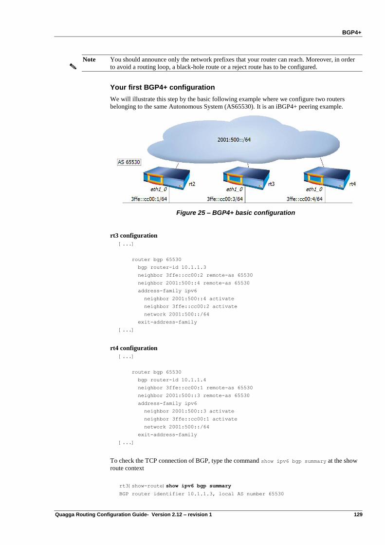
BGP4+
Quagga Routing Configuration Guide- Version 2.12 – revision 1 129
Note You should announce only the network prefixes that your router can reach. Moreover, in order
to avoid a routing loop, a black-hole route or a reject route has to be configured.
Your first BGP4+ configuration
We will illustrate this step by the basic following example where we configure two routers
belonging to the same Autonomous System (AS65530). It is an iBGP4+ peering example.
Figure 25 – BGP4+ basic configuration
rt3 configuration
[...]
router bgp 65530
bgp router-id 10.1.1.3
neighbor 3ffe::cc00:2 remote-as 65530
neighbor 2001:500::4 remote-as 65530
address-family ipv6
neighbor 2001:500::4 activate
neighbor 3ffe::cc00:2 activate
network 2001:500::/64
exit-address-family
[...]
rt4 configuration
[...]
router bgp 65530
bgp router-id 10.1.1.4
neighbor 3ffe::cc00:1 remote-as 65530
neighbor 2001:500::3 remote-as 65530
address-family ipv6
neighbor 2001:500::3 activate
neighbor 3ffe::cc00:1 activate
network 2001:500::/64
exit-address-family
[...]
To check the TCP connection of BGP, type the command show ipv6 bgp summary at the show
route context
rt3{show-route}show ipv6 bgp summary
BGP router identifier 10.1.1.3, local AS number 65530
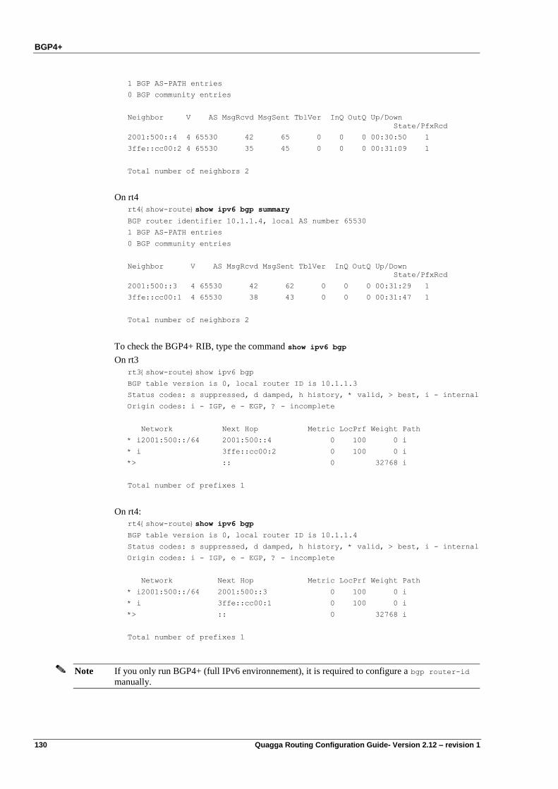
BGP4+
130 Quagga Routing Configuration Guide- Version 2.12 – revision 1
1 BGP AS-PATH entries
0 BGP community entries
Neighbor V AS MsgRcvd MsgSent TblVer InQ OutQ Up/Down
State/PfxRcd
2001:500::4 4 65530 42 65 0 0 0 00:30:50 1
3ffe::cc00:2 4 65530 35 45 0 0 0 00:31:09 1
Total number of neighbors 2
On rt4
rt4{show-route}show ipv6 bgp summary
BGP router identifier 10.1.1.4, local AS number 65530
1 BGP AS-PATH entries
0 BGP community entries
Neighbor V AS MsgRcvd MsgSent TblVer InQ OutQ Up/Down
State/PfxRcd
2001:500::3 4 65530 42 62 0 0 0 00:31:29 1
3ffe::cc00:1 4 65530 38 43 0 0 0 00:31:47 1
Total number of neighbors 2
To check the BGP4+ RIB, type the command show ipv6 bgp
On rt3
rt3{show-route}show ipv6 bgp
BGP table version is 0, local router ID is 10.1.1.3
Status codes: s suppressed, d damped, h history, * valid, > best, i - internal
Origin codes: i - IGP, e - EGP, ? - incomplete
Network Next Hop Metric LocPrf Weight Path
* i2001:500::/64 2001:500::4 0 100 0 i
* i 3ffe::cc00:2 0 100 0 i
*> :: 0 32768 i
Total number of prefixes 1
On rt4:
rt4{show-route}show ipv6 bgp
BGP table version is 0, local router ID is 10.1.1.4
Status codes: s suppressed, d damped, h history, * valid, > best, i - internal
Origin codes: i - IGP, e - EGP, ? - incomplete
Network Next Hop Metric LocPrf Weight Path
* i2001:500::/64 2001:500::3 0 100 0 i
* i 3ffe::cc00:1 0 100 0 i
*> :: 0 32768 i
Total number of prefixes 1
Note If you only run BGP4+ (full IPv6 environnement), it is required to configure a bgp router-id
manually.
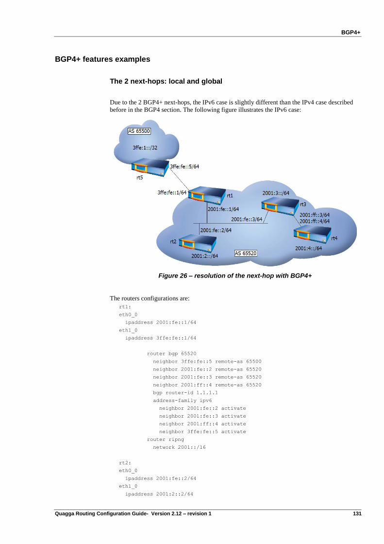
BGP4+
Quagga Routing Configuration Guide- Version 2.12 – revision 1 131
BGP4+ features examples
The 2 next-hops: local and global
Due to the 2 BGP4+ next-hops, the IPv6 case is slightly different than the IPv4 case described
before in the BGP4 section. The following figure illustrates the IPv6 case:
Figure 26 – resolution of the next-hop with BGP4+
The routers configurations are:
rt1:
eth0_0
ipaddress 2001:fe::1/64
eth1_0
ipaddress 3ffe:fe::1/64
router bgp 65520
neighbor 3ffe:fe::5 remote-as 65500
neighbor 2001:fe::2 remote-as 65520
neighbor 2001:fe::3 remote-as 65520
neighbor 2001:ff::4 remote-as 65520
bgp router-id 1.1.1.1
address-family ipv6
neighbor 2001:fe::2 activate
neighbor 2001:fe::3 activate
neighbor 2001:ff::4 activate
neighbor 3ffe:fe::5 activate
router ripng
network 2001::/16
rt2:
eth0_0
ipaddress 2001:fe::2/64
eth1_0
ipaddress 2001:2::2/64
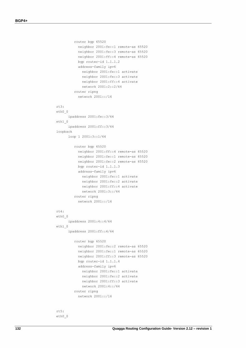
BGP4+
132 Quagga Routing Configuration Guide- Version 2.12 – revision 1
router bgp 65520
neighbor 2001:fe::1 remote-as 65520
neighbor 2001:fe::3 remote-as 65520
neighbor 2001:ff::4 remote-as 65520
bgp router-id 1.1.1.2
address-family ipv6
neighbor 2001:fe::1 activate
neighbor 2001:fe::3 activate
neighbor 2001:ff::4 activate
network 2001:2::2/64
router ripng
network 2001::/16
rt3:
eth0_0
ipaddress 2001:fe::3/64
eth1_0
ipaddress 2001:ff::3/64
loopback
loop 1 2001:3::1/64
router bgp 65520
neighbor 2001:ff::4 remote-as 65520
neighbor 2001:fe::1 remote-as 65520
neighbor 2001:fe::2 remote-as 65520
bgp router-id 1.1.1.3
address-family ipv6
neighbor 2001:fe::1 activate
neighbor 2001:fe::2 activate
neighbor 2001:ff::4 activate
network 2001:3::/64
router ripng
network 2001::/16
rt4:
eth0_0
ipaddress 2001:4::4/64
eth1_0
ipaddress 2001:ff::4/64
router bgp 65520
neighbor 2001:fe::2 remote-as 65520
neighbor 2001:fe::1 remote-as 65520
neighbor 2001:ff::3 remote-as 65520
bgp router-id 1.1.1.4
address-family ipv6
neighbor 2001:fe::1 activate
neighbor 2001:fe::2 activate
neighbor 2001:ff::3 activate
network 2001:4::/64
router ripng
network 2001::/16
rt5:
eth0_0
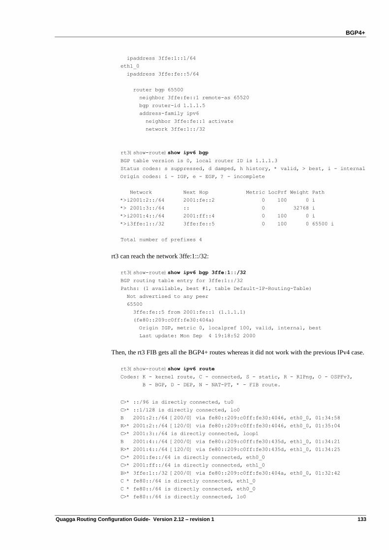
BGP4+
Quagga Routing Configuration Guide- Version 2.12 – revision 1 133
ipaddress 3ffe:1::1/64
eth1_0
ipaddress 3ffe:fe::5/64
router bgp 65500
neighbor 3ffe:fe::1 remote-as 65520
bgp router-id 1.1.1.5
address-family ipv6
neighbor 3ffe:fe::1 activate
network 3ffe:1::/32
rt3{show-route}show ipv6 bgp
BGP table version is 0, local router ID is 1.1.1.3
Status codes: s suppressed, d damped, h history, * valid, > best, i - internal
Origin codes: i - IGP, e - EGP, ? - incomplete
Network Next Hop Metric LocPrf Weight Path
*>i2001:2::/64 2001:fe::2 0 100 0 i
*> 2001:3::/64 :: 0 32768 i
*>i2001:4::/64 2001:ff::4 0 100 0 i
*>i3ffe:1::/32 3ffe:fe::5 0 100 0 65500 i
Total number of prefixes 4
rt3 can reach the network 3ffe:1::/32:
rt3{show-route}show ipv6 bgp 3ffe:1::/32
BGP routing table entry for 3ffe:1::/32
Paths: (1 available, best #1, table Default-IP-Routing-Table)
Not advertised to any peer
65500
3ffe:fe::5 from 2001:fe::1 (1.1.1.1)
(fe80::209:c0ff:fe30:404a)
Origin IGP, metric 0, localpref 100, valid, internal, best
Last update: Mon Sep 4 19:18:52 2000
Then, the rt3 FIB gets all the BGP4+ routes whereas it did not work with the previous IPv4 case.
rt3{show-route}show ipv6 route
Codes: K - kernel route, C - connected, S - static, R - RIPng, O - OSPFv3,
B - BGP, D - DEP, N - NAT-PT, * - FIB route.
C>* ::/96 is directly connected, tu0
C>* ::1/128 is directly connected, lo0
B 2001:2::/64 [200/0] via fe80::209:c0ff:fe30:4046, eth0_0, 01:34:58
R>* 2001:2::/64 [120/0] via fe80::209:c0ff:fe30:4046, eth0_0, 01:35:04
C>* 2001:3::/64 is directly connected, loop1
B 2001:4::/64 [200/0] via fe80::209:c0ff:fe30:435d, eth1_0, 01:34:21
R>* 2001:4::/64 [120/0] via fe80::209:c0ff:fe30:435d, eth1_0, 01:34:25
C>* 2001:fe::/64 is directly connected, eth0_0
C>* 2001:ff::/64 is directly connected, eth1_0
B>* 3ffe:1::/32 [200/0] via fe80::209:c0ff:fe30:404a, eth0_0, 01:32:42
C * fe80::/64 is directly connected, eth1_0
C * fe80::/64 is directly connected, eth0_0
C>* fe80::/64 is directly connected, lo0
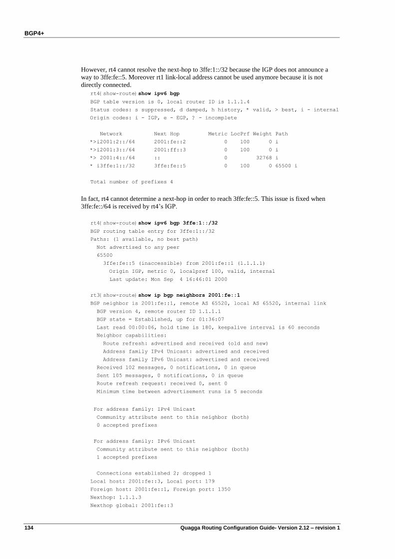
BGP4+
134 Quagga Routing Configuration Guide- Version 2.12 – revision 1
However, rt4 cannot resolve the next-hop to 3ffe:1::/32 because the IGP does not announce a
way to 3ffe:fe::5. Moreover rt1 link-local address cannot be used anymore because it is not
directly connected.
rt4{show-route}show ipv6 bgp
BGP table version is 0, local router ID is 1.1.1.4
Status codes: s suppressed, d damped, h history, * valid, > best, i - internal
Origin codes: i - IGP, e - EGP, ? - incomplete
Network Next Hop Metric LocPrf Weight Path
*>i2001:2::/64 2001:fe::2 0 100 0 i
*>i2001:3::/64 2001:ff::3 0 100 0 i
*> 2001:4::/64 :: 0 32768 i
* i3ffe:1::/32 3ffe:fe::5 0 100 0 65500 i
Total number of prefixes 4
In fact, rt4 cannot determine a next-hop in order to reach 3ffe:fe::5. This issue is fixed when
3ffe:fe::/64 is received by rt4‟s IGP.
rt4{show-route}show ipv6 bgp 3ffe:1::/32
BGP routing table entry for 3ffe:1::/32
Paths: (1 available, no best path)
Not advertised to any peer
65500
3ffe:fe::5 (inaccessible) from 2001:fe::1 (1.1.1.1)
Origin IGP, metric 0, localpref 100, valid, internal
Last update: Mon Sep 4 16:46:01 2000
rt3{show-route}show ip bgp neighbors 2001:fe::1
BGP neighbor is 2001:fe::1, remote AS 65520, local AS 65520, internal link
BGP version 4, remote router ID 1.1.1.1
BGP state = Established, up for 01:36:07
Last read 00:00:06, hold time is 180, keepalive interval is 60 seconds
Neighbor capabilities:
Route refresh: advertised and received (old and new)
Address family IPv4 Unicast: advertised and received
Address family IPv6 Unicast: advertised and received
Received 102 messages, 0 notifications, 0 in queue
Sent 105 messages, 0 notifications, 0 in queue
Route refresh request: received 0, sent 0
Minimum time between advertisement runs is 5 seconds
For address family: IPv4 Unicast
Community attribute sent to this neighbor (both)
0 accepted prefixes
For address family: IPv6 Unicast
Community attribute sent to this neighbor (both)
1 accepted prefixes
Connections established 2; dropped 1
Local host: 2001:fe::3, Local port: 179
Foreign host: 2001:fe::1, Foreign port: 1350
Nexthop: 1.1.1.3
Nexthop global: 2001:fe::3
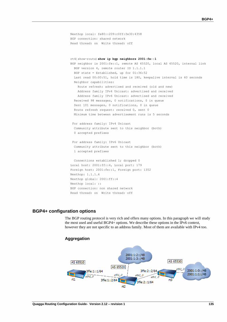
BGP4+
Quagga Routing Configuration Guide- Version 2.12 – revision 1 135
Nexthop local: fe80::209:c0ff:fe30:4358
BGP connection: shared network
Read thread: on Write thread: off
rt4{show-route}show ip bgp neighbors 2001:fe::1
BGP neighbor is 2001:fe::1, remote AS 65520, local AS 65520, internal link
BGP version 4, remote router ID 1.1.1.1
BGP state = Established, up for 01:36:52
Last read 00:00:51, hold time is 180, keepalive interval is 60 seconds
Neighbor capabilities:
Route refresh: advertised and received (old and new)
Address family IPv4 Unicast: advertised and received
Address family IPv6 Unicast: advertised and received
Received 98 messages, 0 notifications, 0 in queue
Sent 101 messages, 0 notifications, 0 in queue
Route refresh request: received 0, sent 0
Minimum time between advertisement runs is 5 seconds
For address family: IPv4 Unicast
Community attribute sent to this neighbor (both)
0 accepted prefixes
For address family: IPv6 Unicast
Community attribute sent to this neighbor (both)
1 accepted prefixes
Connections established 1; dropped 0
Local host: 2001:ff::4, Local port: 179
Foreign host: 2001:fe::1, Foreign port: 1352
Nexthop: 1.1.1.4
Nexthop global: 2001:ff::4
Nexthop local: ::
BGP connection: non shared network
Read thread: on Write thread: off
BGP4+ configuration options
The BGP routing protocol is very rich and offers many options. In this paragraph we will study
the most used and useful BGP4+ options. We describe these options in the IPv6 context,
however they are not specific to an address family. Most of them are available with IPv4 too.
Aggregation
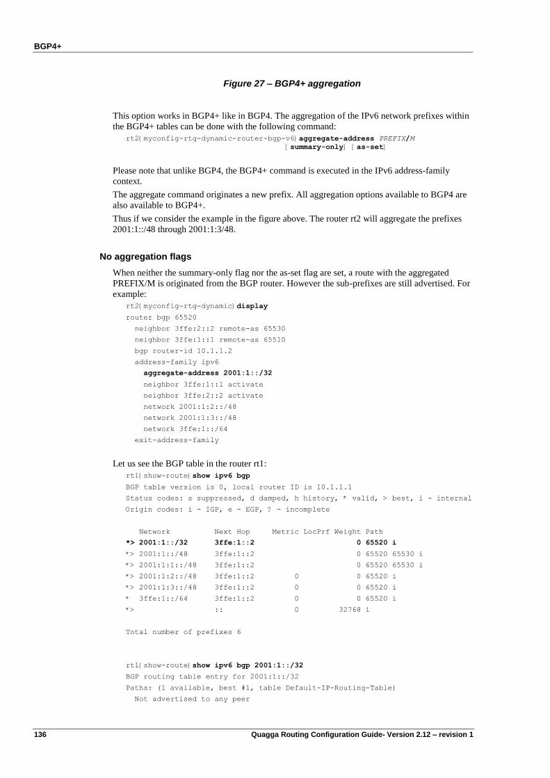
BGP4+
136 Quagga Routing Configuration Guide- Version 2.12 – revision 1
Figure 27 – BGP4+ aggregation
This option works in BGP4+ like in BGP4. The aggregation of the IPv6 network prefixes within
the BGP4+ tables can be done with the following command:
rt2{myconfig-rtg-dynamic-router-bgp-v6}aggregate-address PREFIX/M
[summary-only] [as-set]
Please note that unlike BGP4, the BGP4+ command is executed in the IPv6 address-family
context.
The aggregate command originates a new prefix. All aggregation options available to BGP4 are
also available to BGP4+.
Thus if we consider the example in the figure above. The router rt2 will aggregate the prefixes
2001:1::/48 through 2001:1:3/48.
No aggregation flags
When neither the summary-only flag nor the as-set flag are set, a route with the aggregated
PREFIX/M is originated from the BGP router. However the sub-prefixes are still advertised. For
example:
rt2{myconfig-rtg-dynamic}display
router bgp 65520
neighbor 3ffe:2::2 remote-as 65530
neighbor 3ffe:1::1 remote-as 65510
bgp router-id 10.1.1.2
address-family ipv6
aggregate-address 2001:1::/32
neighbor 3ffe:1::1 activate
neighbor 3ffe:2::2 activate
network 2001:1:2::/48
network 2001:1:3::/48
network 3ffe:1::/64
exit-address-family
Let us see the BGP table in the router rt1:
rt1{show-route}show ipv6 bgp
BGP table version is 0, local router ID is 10.1.1.1
Status codes: s suppressed, d damped, h history, * valid, > best, i - internal
Origin codes: i - IGP, e - EGP, ? - incomplete
Network Next Hop Metric LocPrf Weight Path
*> 2001:1::/32 3ffe:1::2 0 65520 i
*> 2001:1::/48 3ffe:1::2 0 65520 65530 i
*> 2001:1:1::/48 3ffe:1::2 0 65520 65530 i
*> 2001:1:2::/48 3ffe:1::2 0 0 65520 i
*> 2001:1:3::/48 3ffe:1::2 0 0 65520 i
* 3ffe:1::/64 3ffe:1::2 0 0 65520 i
*> :: 0 32768 i
Total number of prefixes 6
rt1{show-route}show ipv6 bgp 2001:1::/32
BGP routing table entry for 2001:1::/32
Paths: (1 available, best #1, table Default-IP-Routing-Table)
Not advertised to any peer
BGP4+
Quagga Routing Configuration Guide- Version 2.12 – revision 1 137
65520, (aggregated by 65520 10.1.1.2)
3ffe:1::2 from 3ffe:1::2 (10.1.1.2)
(fe80::209:c0ff:fe30:4046)
Origin IGP, localpref 100, valid, external, atomic-aggregate, best
Last update: Sat Sep 2 07:23:39 2000
Please note that the aggregated prefix has the atomic-aggregate attribute, which means that the
AS information is lost for the aggregate prefix 2001:1::/32
Note In order not to advertise the sub-prefixes, the flag summary-only can be set. Or a prefix-list or
a distribute-list can be defined to filter them.
Summary-only aggregation flag
When the summary-only flag is set and the as-set flag is not set, only the route with the
aggregated PREFIX/M is originated from the BGP router. The sub-prefixes are not advertised.
Moreover the ID of the router is set within the AS-PATH in order to help traffic engineering.
For example:
rt2{myconfig-rtg-dynamic-router-bgp-v6}aggregate-address 2001:1::/32
summary-only
rt2{show-route}show ipv6 bgp
BGP table version is 0, local router ID is 10.1.1.2
Status codes: s suppressed, d damped, h history, * valid, > best, i - internal
Origin codes: i - IGP, e - EGP, ? - incomplete
Network Next Hop Metric LocPrf Weight Path
*> 2001:1::/32 :: 32768 i
s> 2001:1::/48 3ffe:2::2 0 0 65530 i
s> 2001:1:1::/48 3ffe:2::2 0 0 65530 i
s> 2001:1:2::/48 :: 0 32768 i
s> 2001:1:3::/48 :: 0 32768 i
* 3ffe:1::/64 3ffe:1::1 0 0 65510 i
*> :: 0 32768 i
Total number of prefixes 6
The sub-prefixes which have been suppressed are labeled s.
On the remote peer, only the route to 2001:1::/32 is received by the BGP RIB:
rt1{show-route}show ipv6 bgp
BGP table version is 0, local router ID is 10.1.1.1
Status codes: s suppressed, d damped, h history, * valid, > best, i - internal
Origin codes: i - IGP, e - EGP, ? - incomplete
Network Next Hop Metric LocPrf Weight Path
*> 2001:1::/32 3ffe:1::2 0 65520 i
* 3ffe:1::/64 3ffe:1::2 0 0 65520 i
*> :: 0 32768 i
Total number of prefixes 2
As-set aggregation flag
When the summary-only flag is not set and the as-set flag is set, a route with the aggregated
PREFIX/M is originated from the BGP router. Moreover the information of the previous AS-
BGP4+
138 Quagga Routing Configuration Guide- Version 2.12 – revision 1
PATHs is collected into an unordered list called an AS-SET. This AS-SET, that is included
within the new AS-PATH originated by the router, can help to avoid some networks loops.
However the sub-prefixes are still advertised.
For example:
rt2{running-rtg-dynamic-router-bgp-v6}aggregate-address 2001:1::/32
as-set
The AS information appears between brackets „{‟ „}‟. It is an unordered list of the Autonomous
Systems.
rt2{show-route}show ipv6 bgp
BGP table version is 0, local router ID is 10.1.1.2
Status codes: s suppressed, d damped, h history, * valid, > best, i - internal
Origin codes: i - IGP, e - EGP, ? - incomplete
Network Next Hop Metric LocPrf Weight Path
*> 2001:1::/32 :: 32768 {65530} i
*> 2001:1::/48 3ffe:2::2 0 0 65530 i
*> 2001:1:1::/48 3ffe:2::2 0 0 65530 i
*> 2001:1:2::/48 :: 0 32768 i
*> 2001:1:3::/48 :: 0 32768 i
* 3ffe:1::/64 3ffe:1::1 0 0 65510 i
*> :: 0 32768 i
Total number of prefixes 6
The route to 2001:1::/32 is not announced with the atomic-aggregate flag anymore. It just has
the aggregated flag:
rt2{show-route}show ipv6 bgp 2001:1::/32
BGP routing table entry for 2001:1::/32
Paths: (1 available, best #1, table Default-IP-Routing-Table)
Advertised to non peer-group peers:
3ffe:1::1 3ffe:2::2
{65530}, (aggregated by 65520 10.1.1.2)
:: from :: (10.1.1.2)
Origin IGP, localpref 100, weight 32768, valid, aggregated, local, best
Last update: Sat Sep 2 07:37:51 2000
Combined summary-only and as-set aggregation flags
When both the summary-only and as-set flags are set, a route to the aggregated network
PREFIX/M is originated from the BGP router. Moreover the information of the previous AS-
PATHs is collected into an unordered list called an AS-SET. This AS-SET, that is included
within the new AS-PATH originated by the router, can help to avoid some networks loops. The
sub-prefixes are nomore advertised.
rt2{myconfig-rtg-dynamic-router-bgp-v6}aggregate-address 2001:1::/32
summary-only as-set
For example, rt2 BGP4+ RIB is:
rt2{show-route}show ipv6 bgp
BGP table version is 0, local router ID is 10.1.1.2
Status codes: s suppressed, d damped, h history, * valid, > best, i - internal
Origin codes: i - IGP, e - EGP, ? - incomplete
Network Next Hop Metric LocPrf Weight Path
*> 2001:1::/32 :: 32768 {65530} i
BGP4+
Quagga Routing Configuration Guide- Version 2.12 – revision 1 139
s> 2001:1::/48 3ffe:2::2 0 0 65530 i
s> 2001:1:1::/48 3ffe:2::2 0 0 65530 i
s> 2001:1:2::/48 :: 0 32768 i
s> 2001:1:3::/48 :: 0 32768 i
* 3ffe:1::/64 3ffe:1::1 0 0 65510 i
*> :: 0 32768 i
Total number of prefixes 6
On the remote peer, only the aggregated prefix with the AS-SET is received :
rt1{show-route}show ipv6 bgp
BGP table version is 0, local router ID is 10.1.1.1
Status codes: s suppressed, d damped, h history, * valid, > best, i - internal
Origin codes: i - IGP, e - EGP, ? - incomplete
Network Next Hop Metric LocPrf Weight Path
*> 2001:1::/32 3ffe:1::2 0 65520 {65530} i
* 3ffe:1::/64 3ffe:1::2 0 0 65520 i
*> :: 0 32768 i
Total number of prefixes 2
Confederation
A confederation is a set of many private Autonomous Systems that are joined in order to be
advertised as a single AS. A confederated AS is a confederation of many ASes that are joined by
eBGP and that are running themselves an IGP.
The use cases are:
The join of independent Autonomous Systems into a single AS
The support for multi-homed customers
To avoid the scaling issues of the full-mesh eBGP routers
To configure a BGP4+ confederation use the following command, like in BGP4:
rt2{ myconfig-rtg-dynamic-router-bgp}bgp confederation identifier ASN
where:
ASN is the confederation identifier
Moreover, the union of the private ASes that belong to the same confederation is done with the
following command:
rt2{ myconfig-rtg-dynamic-router-bgp}bgp confederation peers ASN1 … ASNn
where:
ASNi are your private AS Numbers that should be joined.
For example, let us configure the following confederation:
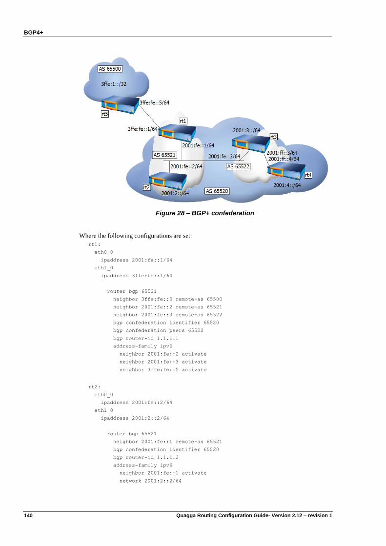
BGP4+
140 Quagga Routing Configuration Guide- Version 2.12 – revision 1
Figure 28 – BGP+ confederation
Where the following configurations are set:
rt1:
eth0_0
ipaddress 2001:fe::1/64
eth1_0
ipaddress 3ffe:fe::1/64
router bgp 65521
neighbor 3ffe:fe::5 remote-as 65500
neighbor 2001:fe::2 remote-as 65521
neighbor 2001:fe::3 remote-as 65522
bgp confederation identifier 65520
bgp confederation peers 65522
bgp router-id 1.1.1.1
address-family ipv6
neighbor 2001:fe::2 activate
neighbor 2001:fe::3 activate
neighbor 3ffe:fe::5 activate
rt2:
eth0_0
ipaddress 2001:fe::2/64
eth1_0
ipaddress 2001:2::2/64
router bgp 65521
neighbor 2001:fe::1 remote-as 65521
bgp confederation identifier 65520
bgp router-id 1.1.1.2
address-family ipv6
neighbor 2001:fe::1 activate
network 2001:2::2/64
BGP4+
Quagga Routing Configuration Guide- Version 2.12 – revision 1 141
rt3:
eth0_0
ipaddress 2001:fe::3/64
eth1_0
ipaddress 2001:ff::3/64
loopback
loop 1 2001:3::1/64
router bgp 65522
neighbor 2001:fe::1 remote-as 65521
neighbor 2001:ff::4 remote-as 65522
bgp confederation identifier 65520
bgp confederation peers 65521
bgp router-id 1.1.1.3
address-family ipv6
neighbor 2001:fe::1 activate
neighbor 2001:ff::4 activate
network 2001:3::/64
rt4:
eth0_0
ipaddress 2001:4::4/64
eth1_0
ipaddress 2001:ff::4/64
router bgp 65522
neighbor 2001:ff::3 remote-as 65522
bgp confederation identifier 65520
bgp router-id 1.1.1.4
address-family ipv6
neighbor 2001:ff::3 activate
network 2001:4::/64
However, when rt5 peers with rt1, it peers to the AS 65520 that is rt1‟s BGP confederation
identifier. It does not peer to the AS 65521 that is internal to the AS 65520:
rt5:
eth0_0
ipaddress 3ffe:1::1/64
eth1_0
ipaddress 3ffe:fe::5/64
router bgp 65500
neighbor 3ffe:fe::1 remote-as 65520
bgp router-id 1.1.1.5
address-family ipv6
neighbor 3ffe:fe::1 activate
network 3ffe:1::/32
You can check this configuration on rt3 that displays the confederation path between
parentheses:
rt3{show-route}show ipv6 bgp
BGP table version is 0, local router ID is 1.1.1.3
Status codes: s suppressed, d damped, h history, * valid, > best, i - internal
Origin codes: i - IGP, e - EGP, ? - incomplete
Network Next Hop Metric LocPrf Weight Path
BGP4+
142 Quagga Routing Configuration Guide- Version 2.12 – revision 1
*> 2001:2::/64 2001:fe::2 0 100 0 (65521) i
*> 2001:3::/64 :: 0 32768 i
*>i2001:4::/64 2001:ff::4 0 100 0 i
*> 3ffe:1::/32 3ffe:fe::5 0 100 0 (65521) 65500 i
Total number of prefixes 4
rt3{show-route}show ipv6 bgp 3ffe:1::
BGP routing table entry for 3ffe:1::/32
Paths: (1 available, best #1, table Default-IP-Routing-Table)
Advertised to non peer-group peers:
2001:ff::4
(65521) 65500
3ffe:fe::5 from 2001:fe::1 (1.1.1.1)
(fe80::209:c0ff:fe30:404a)
Origin IGP, metric 0, localpref 100, valid, confed-external, best
Last update: Mon Sep 4 01:30:26 2000
Then the FIB of rt3 is:
rt3{show-route}show ipv6 route
Codes: K - kernel route, C - connected, S - static, R - RIPng, O - OSPFv3,
B - BGP, D - DEP, N - NAT-PT, * - FIB route.
C>* ::/96 is directly connected, tu0
C>* ::1/128 is directly connected, lo0
B>* 2001:2::/64 [200/0] via fe80::209:c0ff:fe30:404a, eth0_0, 00:17:03
C>* 2001:3::/64 is directly connected, loop1
B>* 2001:4::/64 [200/0] via fe80::209:c0ff:fe30:435d, eth1_0, 16:31:20
C>* 2001:fe::/64 is directly connected, eth0_0
C>* 2001:ff::/64 is directly connected, eth1_0
B>* 3ffe:1::/32 [200/0] via fe80::209:c0ff:fe30:404a, eth0_0, 16:40:21
C * fe80::/64 is directly connected, eth1_0
C * fe80::/64 is directly connected, eth0_0
C>* fe80::/64 is directly connected, lo0
Note that rt3 can route to the AS65500 that owns the prefix 3ffe:1::/32 whereas on the Figure 12
– BGP4 confederation (p. 64) rt3 could not reach the AS65500‟s next-hop.
Route Reflector
Another solution for scaling iBGP full mesh issue within an autonomous system is Route
Reflectors.
The route reflectors substitute the full mesh TCP session between all the iBGP routers of a
single AS, with a TCP session between the iBGP routers and the router that is configured as a
reflector.
By default a BGP router will never advertise a route learned via another iBGP router to a third
iBGP router. The route reflection mechanism relaxes this restriction and allows iBGP routers to
advertise route to a third iBGP router in transparent way (reflection). The route reflection
mechanism is a good solution to the iBGP full mesh scalability problem.
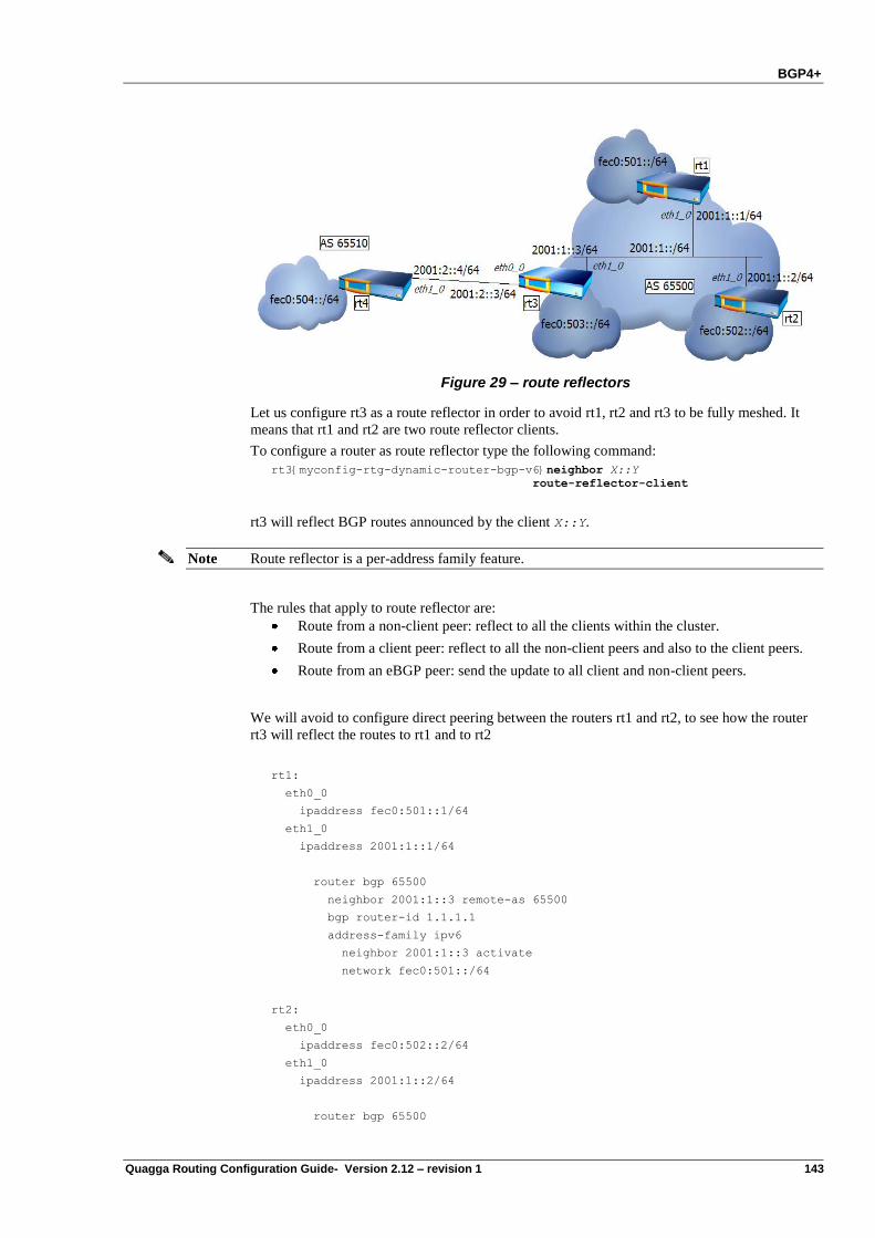
BGP4+
Quagga Routing Configuration Guide- Version 2.12 – revision 1 143
Figure 29 – route reflectors
Let us configure rt3 as a route reflector in order to avoid rt1, rt2 and rt3 to be fully meshed. It
means that rt1 and rt2 are two route reflector clients.
To configure a router as route reflector type the following command:
rt3{myconfig-rtg-dynamic-router-bgp-v6}neighbor X::Y
route-reflector-client
rt3 will reflect BGP routes announced by the client X::Y.
Note Route reflector is a per-address family feature.
The rules that apply to route reflector are:
Route from a non-client peer: reflect to all the clients within the cluster.
Route from a client peer: reflect to all the non-client peers and also to the client peers.
Route from an eBGP peer: send the update to all client and non-client peers.
We will avoid to configure direct peering between the routers rt1 and rt2, to see how the router
rt3 will reflect the routes to rt1 and to rt2
rt1:
eth0_0
ipaddress fec0:501::1/64
eth1_0
ipaddress 2001:1::1/64
router bgp 65500
neighbor 2001:1::3 remote-as 65500
bgp router-id 1.1.1.1
address-family ipv6
neighbor 2001:1::3 activate
network fec0:501::/64
rt2:
eth0_0
ipaddress fec0:502::2/64
eth1_0
ipaddress 2001:1::2/64
router bgp 65500
BGP4+
144 Quagga Routing Configuration Guide- Version 2.12 – revision 1
neighbor 2001:1::3 remote-as 65500
bgp router-id 1.1.1.2
address-family ipv6
neighbor 2001:1::3 activate
network fec0:502::/64
rt3:
eth0_0
ipaddress 2001:2::3/64
eth1_0
ipaddress 2001:1::3/64
router bgp 65500
neighbor 2001:1::2 remote-as 65500
neighbor 2001:1::1 remote-as 65500
neighbor 2001:2::4 remote-as 65510
bgp router-id 1.1.1.3
address-family ipv6
neighbor 2001:1::1 activate
neighbor 2001:1::1 route-reflector-client
neighbor 2001:1::2 activate
neighbor 2001:1::2 route-reflector-client
neighbor 2001:2::4 activate
network fec0:503::/64
rt4:
eth0_0
ipaddress fec0:504::4/64
eth1_0
ipaddress 2001:2::4/64
router bgp 65510
neighbor 2001:2::3 remote-as 65500
bgp router-id 1.1.1.4
address-family ipv6
neighbor 2001:2::3 activate
network fec0:504::/64
Let us check how the network fec0:501::/64 is reflected on the router rt2:
rt2{show-route}show ipv6 bgp
BGP table version is 0, local router ID is 1.1.1.2
Status codes: s suppressed, d damped, h history, * valid, > best, i - internal
Origin codes: i - IGP, e - EGP, ? - incomplete
Network Next Hop Metric LocPrf Weight Path
*>ifec0:501::/64 2001:1::1 0 100 0 i
*> fec0:502::/64 :: 0 32768 i
*>ifec0:503::/64 2001:1::3 0 100 0 i
*>ifec0:504::/64 2001:2::4 0 100 0 65510 i
Total number of prefixes 4
rt2{show-route}show ipv6 bgp fec0:501::/64
BGP routing table entry for fec0:501::/64
Paths: (1 available, best #1, table Default-IP-Routing-Table)
Not advertised to any peer
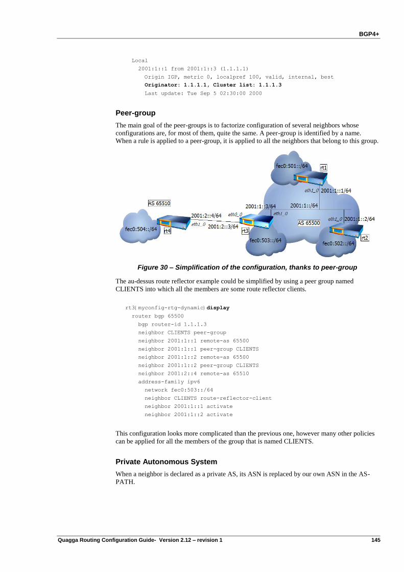
BGP4+
Quagga Routing Configuration Guide- Version 2.12 – revision 1 145
Local
2001:1::1 from 2001:1::3 (1.1.1.1)
Origin IGP, metric 0, localpref 100, valid, internal, best
Originator: 1.1.1.1, Cluster list: 1.1.1.3
Last update: Tue Sep 5 02:30:00 2000
Peer-group
The main goal of the peer-groups is to factorize configuration of several neighbors whose
configurations are, for most of them, quite the same. A peer-group is identified by a name.
When a rule is applied to a peer-group, it is applied to all the neighbors that belong to this group.
Figure 30 – Simplification of the configuration, thanks to peer-group
The au-dessus route reflector example could be simplified by using a peer group named
CLIENTS into which all the members are some route reflector clients.
rt3{myconfig-rtg-dynamic}display
router bgp 65500
bgp router-id 1.1.1.3
neighbor CLIENTS peer-group
neighbor 2001:1::1 remote-as 65500
neighbor 2001:1::1 peer-group CLIENTS
neighbor 2001:1::2 remote-as 65500
neighbor 2001:1::2 peer-group CLIENTS
neighbor 2001:2::4 remote-as 65510
address-family ipv6
network fec0:503::/64
neighbor CLIENTS route-reflector-client
neighbor 2001:1::1 activate
neighbor 2001:1::2 activate
This configuration looks more complicated than the previous one, however many other policies
can be applied for all the members of the group that is named CLIENTS.
Private Autonomous System
When a neighbor is declared as a private AS, its ASN is replaced by our own ASN in the AS-
PATH.
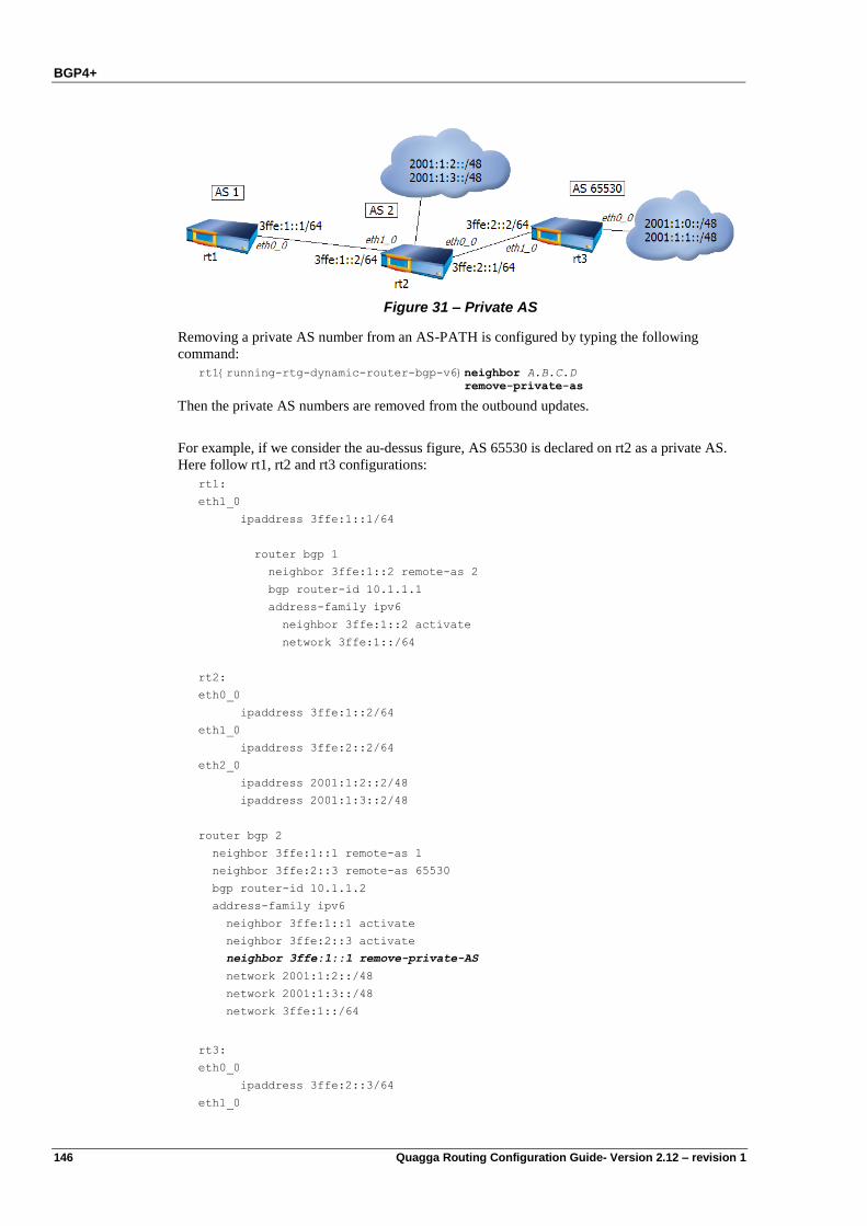
BGP4+
146 Quagga Routing Configuration Guide- Version 2.12 – revision 1
Figure 31 – Private AS
Removing a private AS number from an AS-PATH is configured by typing the following
command:
rt1{running-rtg-dynamic-router-bgp-v6}neighbor A.B.C.D
remove-private-as
Then the private AS numbers are removed from the outbound updates.
For example, if we consider the au-dessus figure, AS 65530 is declared on rt2 as a private AS.
Here follow rt1, rt2 and rt3 configurations:
rt1:
eth1_0
ipaddress 3ffe:1::1/64
router bgp 1
neighbor 3ffe:1::2 remote-as 2
bgp router-id 10.1.1.1
address-family ipv6
neighbor 3ffe:1::2 activate
network 3ffe:1::/64
rt2:
eth0_0
ipaddress 3ffe:1::2/64
eth1_0
ipaddress 3ffe:2::2/64
eth2_0
ipaddress 2001:1:2::2/48
ipaddress 2001:1:3::2/48
router bgp 2
neighbor 3ffe:1::1 remote-as 1
neighbor 3ffe:2::3 remote-as 65530
bgp router-id 10.1.1.2
address-family ipv6
neighbor 3ffe:1::1 activate
neighbor 3ffe:2::3 activate
neighbor 3ffe:1::1 remove-private-AS
network 2001:1:2::/48
network 2001:1:3::/48
network 3ffe:1::/64
rt3:
eth0_0
ipaddress 3ffe:2::3/64
eth1_0
BGP4+
Quagga Routing Configuration Guide- Version 2.12 – revision 1 147
ipaddress 2001:1::/48
ipaddress 2001:1:1::/48
router bgp 65530
neighbor 3ffe:2::2 remote-as 2
bgp router-id 10.1.1.3
address-family ipv6
neighbor 3ffe:2::2 activate
network 2001:1::/48
network 2001:1:1::/48
Then the AS path on rt1 and rt2 for both networks is as follows:
rt2{show-route}show ipv6 bgp
BGP table version is 0, local router ID is 10.1.1.2
Status codes: s suppressed, d damped, h history, * valid, > best, i - internal
Origin codes: i - IGP, e - EGP, ? - incomplete
Network Next Hop Metric LocPrf Weight Path
*> 2001:1::/48 3ffe:2::3 0 0 65530 i
*> 2001:1:1::/48 3ffe:2::3 0 0 65530 i
*> 2001:1:2::/48 :: 0 32768 i
*> 2001:1:3::/48 :: 0 32768 i
* 3ffe:1::/64 3ffe:1::1 0 0 1 i
*> :: 0 32768 i
Total number of prefixes 5
However, the rt1 BGP RIB does not contain the 65530 AS number:
rt1{show-route}show ipv6 bgp
BGP table version is 0, local router ID is 10.1.1.1
Status codes: s suppressed, d damped, h history, * valid, > best, i - internal
Origin codes: i - IGP, e - EGP, ? - incomplete
Network Next Hop Metric LocPrf Weight Path
*> 2001:1::/48 3ffe:1::2 0 2 i
*> 2001:1:1::/48 3ffe:1::2 0 2 i
*> 2001:1:2::/48 3ffe:1::2 0 0 2 i
*> 2001:1:3::/48 3ffe:1::2 0 0 2 i
* 3ffe:1::/64 3ffe:1::2 0 0 2 i
*> :: 0 32768 i
Total number of prefixes 5
From rt1, the private AS number seems to be originated from the AS 65520. This feature is very
useful when an ISP offers multihoming access to a customer or to monitor the route of the
customers who are not required to ask for an ASN from the IANA.
rt1 AS-PATHs are free from private AS numbers, AS-PATHs to networks 2001:1::/48 and
2001:1:1::/48 only make reference to AS 2. This feature is very useful when an ISP offers
multihoming access to a customer or to monitor the route of the customers who are not required
to ask for an ASN from the IANA.
BGP4+
148 Quagga Routing Configuration Guide- Version 2.12 – revision 1
BGP4+ states
Like for BGP4, the BGP4+ states reflect the state of the BGP4+ session. A valid BGP4+ session
must be in ESTABLISHED state. Its state can be verified with the following command:
rt1{show-route}show ipv6 bgp summary
BGP router identifier 10.1.1.1, local AS number 65510
2 BGP AS-PATH entries
0 BGP community entries
Neighbor V AS MsgRcvd MsgSent TblVer InQ OutQ Up/Down State/PfxRcd
3ffe:1::2 4 65520 26 19 0 0 0 00:14:11 5
Total number of neighbors 1
The BGP states are: IDLE, ACTIVE, CONNECT, OPENSENT, OPENCONFIRM, and
ESTABLISHED.
IDLE state:
the router will not accept connections from the peer. This state is entered
briefly after a connection has timed out.
ACTIVE state:
the router is listening for connection requests from the peers.
CONNECT state:
the router has sent out an active TCP connection request to the peer.
OPENSENT and OPENCONFIRM states:
the two peers are exchanging packets in order to establish their BGP
session. If the exchanges are successful, the peers will enter the
ESTABLISHED state.
The peers must continue to exchange periodic KEEPALIVE packets to remain in the established
state, unless the negotiated hold time is 0.
show ipv6 bgp
This command displays the IPv6 RIB of the BGP4+ protocol.
rt1{show-route}show ipv6 bgp
BGP table version is 0, local router ID is 10.1.1.2
Status codes: s suppressed, d damped, h history, * valid, > best, i - internal
Origin codes: i - IGP, e - EGP, ? - incomplete
Network Next Hop Metric LocPrf Weight Path
*> 2001:1::/48 3ffe:2::2 0 0 65530 i
*> 2001:1:1::/48 3ffe:2::2 0 0 65530 i
*> 2001:1:2::/48 :: 0 32768 i
*> 2001:1:3::/48 :: 0 32768 i
* 3ffe:1::/64 3ffe:1::1 0 0 65510 i
*> :: 0 32768 i
Total number of prefixes 5
The various fields that are displayed, are described in the following list:
Local router ID --- This id is used to identify the router, it must be manually configured in the
format of IPv4 address, using the command bgp router-id.
Status codes:
o s means the entry is suppressed
o d means the prefix was dampened (in case dampening is enabled)
BGP4+
Quagga Routing Configuration Guide- Version 2.12 – revision 1 149
o * means the entry is valid
o > in case there are multiple entries for this prefix > indicates the best one
o i means that this entry was learned by interior BGP (in the same AS)
o e means that this entry was learned by exterior BGP (different AS)
o ? means that this entry was learned through redistribution
Origin codes:
o i means that the origin of this entry is interior BGP (in the same AS)
o e means that the origin of this entry is exterior BGP (different AS)
o ? means that the origin of this entry is redistribution
Network This is the prefix entry in the BGP4+ RIB
Next Hop This is the next-hop attribute advertised by BGP4+ in case the next-hop is
„::‟ it means that this prefix is originated locally.
Metric This the Multi-exit Descriminator value (see the BGP options)
LocPrf This is the local preference value (see the BGP options) by default it is set
to 100
Weight This the weight associated to the prefix (See BGP options) by default the
received routes is set to 0 while the weight of local routes is 32768
Flush BGP4+ sessions
The principle is the same in IPv6 with BGP4+ like in IPv4 with BGP4. If you have configured
or changed a policy with a BGP neighbor, you should manually reset a BGP session. You may
also want to reset sessions each time you think there is a problem of integrity with neighbor‟s
information.
The following command is used for this purpose:
rt1{}flush bgp ipv6 X:X::X:X|ASN|all [param]
Where:
X:X::X:X is the IPv6 address of the remote BGP router
ASN is a peer AS number
all represents all remote BGP peers
external represents external BGP peers
peer-group represents members of peer-group
view represents all remote BGP peers
param is a parameter for update direction or reconfig: in|out|soft|rsclient
If you used the keyword soft, the session is not reset but all routing updates are resent, therefore
the following command is generally advised when you configured a route-map or a filter and
you want to update the neighbor‟s BGP data:
rt1{}flush bgp ipv6 X:X::X:X soft out
Another example is to use the following command to reset a session with a specific neighbor.
The relationship will then become idle and the reestablished:
rt1{}flush bgp ipv6 X:X::X:X out
Conversely, keyword in is used for inbound reconfiguration.
BGP4+
150 Quagga Routing Configuration Guide- Version 2.12 – revision 1
Before using the command flush, you may need to configure inbound soft reconfiguration with
the considered neighbor.
Route refresh
This feature is the same as for IPv4. Like in IPv4, Route Refresh is enabled by default.
When the command flush is used, Route Refresh messages are sent to the peers, the router
receives one or more Update packets with all the routes of the Adj-RIB-Out. Example:
rt1{}flush bgp ipv6 all soft in
rt1{show-route}show route
rt1{show-route}show ipv6 bgp neighbors
BGP neighbor is 3ffe::2:2, remote AS 2, local AS 1, external link
BGP version 4, remote router ID 10.23.0.2
BGP state = Established, up for 00:31:41
Last read 00:00:10, hold time is 180, keepalive interval is 60 seconds
Neighbor capabilities:
Route refresh: advertised and received(old & new)
Address family IPv4 Unicast: advertised and received
Address family IPv6 Unicast: advertised and received
Message statistics:
Inq depth is 0
Outq depth is 0
Sent Rcvd
Opens: 1 0
Notifications: 0 0
Updates: 2 4
Keepalives: 33 32
Route Refresh: 1 0
Capability: 0 0
Total: 37 36
Soft reconfiguration
Like in IPv4, when using the BGP soft reconfiguration, all the updates received from the
neighbors will be stored unmodified regardless of the inbound policy. The feature should be
used on routers that have enough RAM.
The command to enable soft reconfiguration with a peer can be used as follows:
rt1{myconfig-rtg-dynamic-router-bgp}neighbor X:X::X:X soft-reconfiguration inbound
After this command, you may for example define an access list to accept some routes from a
neighbor X:X::X:X :
rt1{myconfig-rtg-dynamic}ipv6 access-list my_acl permit 3ffe:506::/32
Apply to the incoming routes the distribute list policy name based on this access-list:
rt1{myconfig-rtg-dynamic-router-bgp}neighbor X:X::X:X distribute-list my_acl in
A soft reset uses stored prefix information to reconfigure and activate BGP routing tables
without tearing down existing peering session. No route refresh packet is sent to the peer during
soft reconfiguration is enabled.
When the command flush is used, if Soft Reconfiguration is enabled, Route Refresh message is
not sent :
rt1{}flush bgp ipv6 X:X::X:X soft in
rt1{show-route}show route
rt1{show-route}show ipv6 bgp neighbors
…
BGP4+
Quagga Routing Configuration Guide- Version 2.12 – revision 1 151
Route Refresh: 1 0
Route Refresh count is not incremented.
BGP4+ Graceful Restart Capability
The capability is the same in IPv6 as in IPv4.
BGP4+ Backdoor
Like in IPv4, this feature allows a BGP speaker to use an IGP instead of eBGP to learn a
particular route
The command format in IPv6 is as follows:
rt1{myconfig-rtg-dynamic-router-bgp-v6}network A:D::/M backdoor
Where:
A:D:: is the IPv6 prefix network.
M is the length of this network prefix
To disable the backdoor, enter the following command:
rt1{myconfig-rtg-dynamic-router-bgp-v6}delete network A:D::/M backdoor
IS-IS in IPv6 networks
152 Quagga Routing Configuration Guide- Version 2.12 – revision 1
Chapter 11 IS-IS in IPv6 networks
Introduction
Principles are the same for IPv6 as for IPv4.
Configuring IS-IS
In IS-IS, a routing domain may be configured as a single area or it may be divided in to multiple
areas. Level 1 systems route traffic within an area, whereas inter-area traffic is routed by level-2
systems.
Enable IS-IS
It can be enabled via the following virtual terminal commands:
...
rt1{}edit conf myconfig
rt1{myconfig}rtg
rt1{myconfig-rtg}dynamic
rt1{myconfig-rtg-dynamic}router isis instance-tag
Where:
instance-tag is any string used to identify the instance, eg,
rt1{myconfig-rtg-dynamic}router isis instance AAA
In the same way, to disable IS-IS, type the following command:
rt1{myconfig-rtg-dynamic}delete router isis AAA
Activate IS-IS
To activate IS-IS , assign a Network Entity Title (NET) to the Intermediate System,
rt1{myconfig-rtg-dynamic-router-isis}net network entity title
NET can be any CLNP address unique within an area for Level-1 IS and unique within
a domain for Level-2 IS. First three octet (49.0001 in the following example), known as
Area ID, must be unique for an area within a domain. For IP only networks, typically
first octet of NET called AFI is taken as 49 (representing private networks). Next six
octet (0000.0000.0001in the following example), known as system ID, is unique within
an area for Level-1 system and unique within a domain for Level-2 systems, eg,
rt1{myconfig-rtg-dynamic-router-ospf} net 49.0001.0000.0000.0001.00
IS-IS in IPv6 networks
Quagga Routing Configuration Guide- Version 2.12 – revision 1 153
To configure network, add one or more network interfaces to the IS-IS instance using following
command:
rt1{myconfig-rtg-dynamic-router-ospf}interface ifname
rt1{myconfig-rtg-dynamic-interface}ipv6 router isis instance-tag
Where:
ifname is the name of a network interface. IS-IS will be enabled on the network
interface and it will announce the link in its LSPs.
Verifying IS-IS configuration
The following commands can be used to verify IS-IS operation.
This command dumps the IS-IS RIB:
rt1{show-route}show ipv6 route isis
This command displays the state of the relations with the neighbors:
rt1{show-route}show isis neighbor [detail]
This command displays the IS-IS databases (the Link-State databases) of each area:
rt1{show-route}show isis database [detail]
IS-IS Configuration Commands
The following commands can be used to set various IS-IS options:
is-type rt1{myconfig-rtg-dynamic-router-isis}is-type [level-1 | level-1-2 | level-2-only]
Sets the level of an IS. To reset it to default value, use delete form:
rt1{myconfig-rtg-dynamic-router-isis}delete is-type [level-1 | level-1-2 | level-
2-only]
Default: level-1-2
This command is executed at router isis configuration level.
lsp-gen-interval rt1{myconfig-rtg-dynamic-router-isis}lsp-gen-interval [level-1|level-2] [1-120]
Set tshe minimum interval between regeneration of same LSP in seconds. To reset it to default
value, use delete form:
rt1{myconfig-rtg-dynamic-router-isis}delete lsp-gen-interval [level-1|level-2]
[1-120]
Default: 5 seconds
This command is executed at router isis configuration level.
lsp-refresh-interval rt1{myconfig-rtg-dynamic-router-isis}lsp-gen-interval value
Sets the maximum interval between regeneration of same LSP in seconds. To reset it to default
value, use delete form:
rt1{myconfig-rtg-dynamic-router-isis}delete lsp-gen-interval value
Default: 900 seconds
This command is executed at router isis configuration level.
lsp-lifetime
IS-IS in IPv6 networks
154 Quagga Routing Configuration Guide- Version 2.12 – revision 1
rt1{myconfig-rtg-dynamic-router-isis}lsp-lifetime [level-1|level-2] [380-65535]
Sets lifetime of LSPs generated by an IS. To reset it to default value, use delete form:
rt1{myconfig-rtg-dynamic-router-isis}delete lsp-gen-interval [level-1|level-2]
[380-65535]
Default: 1200 seconds
This command is executed at router isis configuration level.
lsp-mtu rt1{myconfig-rtg-dynamic-router-isis}lsp-mtu value
Sets the maximum size of a LSP generated by an IS. To reset it to default value, use delete form:
rt1{myconfig-rtg-dynamic-router-isis}delete lsp-mtu value
Default: 900 seconds
Note: The maximum size of a LSP should not be greater that path MTU for a network link.
This command is executed at router isis configuration level.
max-area-addresses rt1{myconfig-rtg-dynamic-router-isis}max-area-addresses value
Sets the maximum area addresses permitted for an IS. To reset it to default value, use delete
form:
rt1{myconfig-rtg-dynamic-router-isis}delete max-area-addresses value
Default: 3
Note: Maximum area addresses should be same throughout a domain.
This command is executed at router isis configuration level.
redistribute (external routes redistribution) rt1{myconfig-rtg-dynamic-router-isis}redistribute [bgp|kernel|ospf|rip|static]
ipv6 [routemap value]
Allows routes not learned through IS-IS to be redistributed in IS-IS network as an external route.
Routemap may be specified to filter the routes to be redistributed. To reset it to default state, use
delete form:
rt1{myconfig-rtg-dynamic-router-isis}delete redistribute
[bgp|kernel|ospf|rip|static] ipv6
Default: Disabled
This command is executed at router isis configuration level.
redistribute (route leakage) rt1{myconfig-rtg-dynamic-router-isis}redistribute level-2 into level-1 [routemap
value]
Allows routes learned through Level-2 routing to be listed in Level-1 LSP. Routemap may be
specified to filter the routes to be listed. To reset it to default state, use delete form:
rt1{myconfig-rtg-dynamic-router-isis}delete redistribute level-2 into level-1
Default: Disabled
This command may be used to specify the routemap to be used to filter the listing of routes
learned via Level-1 routing in Level-2 LSP.
rt1{myconfig-rtg-dynamic-router-isis}redistribute level-1 into level-2 routemap
value
To reset it to default state, use delete form:
rt1{myconfig-rtg-dynamic-router-isis}delete redistribute level-1 into level-2
Default: No routemap.
This command is executed at router isis configuration level.
spf-interval rt1{myconfig-rtg-dynamic-router-isis}spf-interval [1-120]
IS-IS in IPv6 networks
Quagga Routing Configuration Guide- Version 2.12 – revision 1 155
Sets the maximum frequency that the Dijkstra routing calculation algorithm can run. To reset it
to default state, use delete form:
rt1{myconfig-rtg-dynamic-router-isis}delete spf-interval
Default: 60 sec
This command is executed at router isis configuration level.
zero-age-lifetime rt1{myconfig-rtg-dynamic-router-isis}zero-age-lifetime value
Sets the the interval, IS-IS should retain LSP header before purging it after expiry of lifetime of
a LSP. To reset it to default state, use delete form:
rt1{myconfig-rtg-dynamic-router-isis}delete zero-age-lifetime
Default: 60 sec
This command is executed at router isis configuration level.
isis circuit-type rt1{myconfig-rtg-dynamic-interface}isis circuit-type [level-1|level-1-2|level-2-
only]
Sets the type of IS-IS adjacency for an interface. To reset it to default state, use delete form:
rt1{myconfig-rtg-dynamic-interface}delete isis circuit-type [level-1|level-1-
2|level-2-only]
Default: level-1-2
This command is executed at interface configuration level.
isis csnp-interval rt1{myconfig-rtg-dynamic-interface}isis csnp-interval value [level-1 | level-2]
Sets the number of seconds between transmission of CSNP packets for an interface. To reset it
to default state, use delete form:
rt1{myconfig-rtg-dynamic-interface}delete isis csnp-interval value [level-1 |
level-2]
Default: 10 seconds
This command is executed interface configuration level.
isis hello-interval rt1{myconfig-rtg-dynamic-interface}isis hello-interval value [level-1 | level-2]
Sets the number of seconds between transmission of hello packets for an interface. To reset it to
default state, use delete form:
rt1{myconfig-rtg-dynamic-interface}delete isis hello-interval value [level-1 |
level-2]
Default: 10 seconds
This command is executed at interface configuration level.
isis hello-multiplier rt1{myconfig-rtg-dynamic-interface}isis hello-multiplier value
Sets the multiplier used to determine how long to hold an IS-IS hello packet before declaring an
adjacency down on an interface. To reset it to default state, use delete form:
rt1{myconfig-rtg-dynamic-interface}delete isis hello-multiplier
Default: 3
This command is executed interface configuration level.
isis lsp-interval rt1{myconfig-rtg-dynamic-interface}isis lsp-interval value
Sets the maximum interval between successive transmissions of LSPs on an interface in
milliseconds. To reset it to default state, use delete form:
rt1{myconfig-rtg-dynamic-interface}delete isis lsp-interval
Default: 33 msec
This command is executed at interface configuration level.
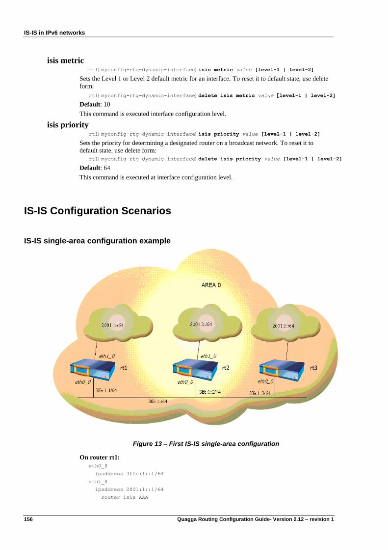
IS-IS in IPv6 networks
156 Quagga Routing Configuration Guide- Version 2.12 – revision 1
isis metric rt1{myconfig-rtg-dynamic-interface}isis metric value [level-1 | level-2]
Sets the Level 1 or Level 2 default metric for an interface. To reset it to default state, use delete
form:
rt1{myconfig-rtg-dynamic-interface}delete isis metric value [level-1 | level-2]
Default: 10
This command is executed interface configuration level.
isis priority rt1{myconfig-rtg-dynamic-interface}isis priority value [level-1 | level-2]
Sets the priority for determining a designated router on a broadcast network. To reset it to
default state, use delete form:
rt1{myconfig-rtg-dynamic-interface}delete isis priority value [level-1 | level-2]
Default: 64
This command is executed at interface configuration level.
IS-IS Configuration Scenarios
IS-IS single-area configuration example
Figure 13 – First IS-IS single-area configuration
On router rt1:
eth0_0
ipaddress 3ffe:1::1/64
eth1_0
ipaddress 2001:1::1/64
router isis AAA
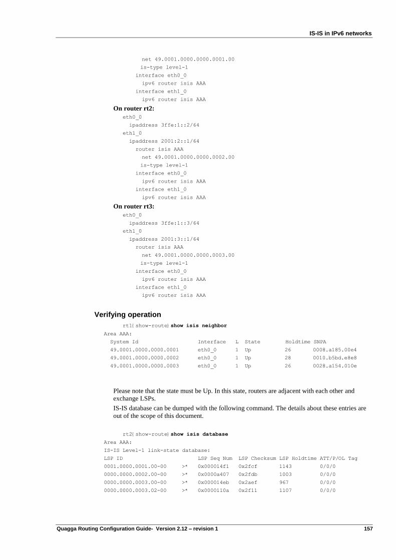
IS-IS in IPv6 networks
Quagga Routing Configuration Guide- Version 2.12 – revision 1 157
net 49.0001.0000.0000.0001.00
is-type level-1
interface eth0_0
ipv6 router isis AAA
interface eth1_0
ipv6 router isis AAA
On router rt2:
eth0_0
ipaddress 3ffe:1::2/64
eth1_0
ipaddress 2001:2::1/64
router isis AAA
net 49.0001.0000.0000.0002.00
is-type level-1
interface eth0_0
ipv6 router isis AAA
interface eth1_0
ipv6 router isis AAA
On router rt3:
eth0_0
ipaddress 3ffe:1::3/64
eth1_0
ipaddress 2001:3::1/64
router isis AAA
net 49.0001.0000.0000.0003.00
is-type level-1
interface eth0_0
ipv6 router isis AAA
interface eth1_0
ipv6 router isis AAA
Verifying operation
rt1{show-route}show isis neighbor
Area AAA:
System Id Interface L State Holdtime SNPA
49.0001.0000.0000.0001 eth0_0 1 Up 26 0008.a185.00e4
49.0001.0000.0000.0002 eth0_0 1 Up 28 0010.b5bd.e8e8
49.0001.0000.0000.0003 eth0_0 1 Up 26 0028.a154.010e
Please note that the state must be Up. In this state, routers are adjacent with each other and
exchange LSPs.
IS-IS database can be dumped with the following command. The details about these entries are
out of the scope of this document.
rt2{show-route}show isis database
Area AAA:
IS-IS Level-1 link-state database:
LSP ID LSP Seq Num LSP Checksum LSP Holdtime ATT/P/OL Tag
0001.0000.0001.00-00 >* 0x000014f1 0x2fcf 1143 0/0/0
0000.0000.0002.00-00 >* 0x0000a407 0x2fdb 1003 0/0/0
0000.0000.0003.00-00 >* 0x000014eb 0x2aef 967 0/0/0
0000.0000.0003.02-00 >* 0x0000110a 0x2f11 1107 0/0/0
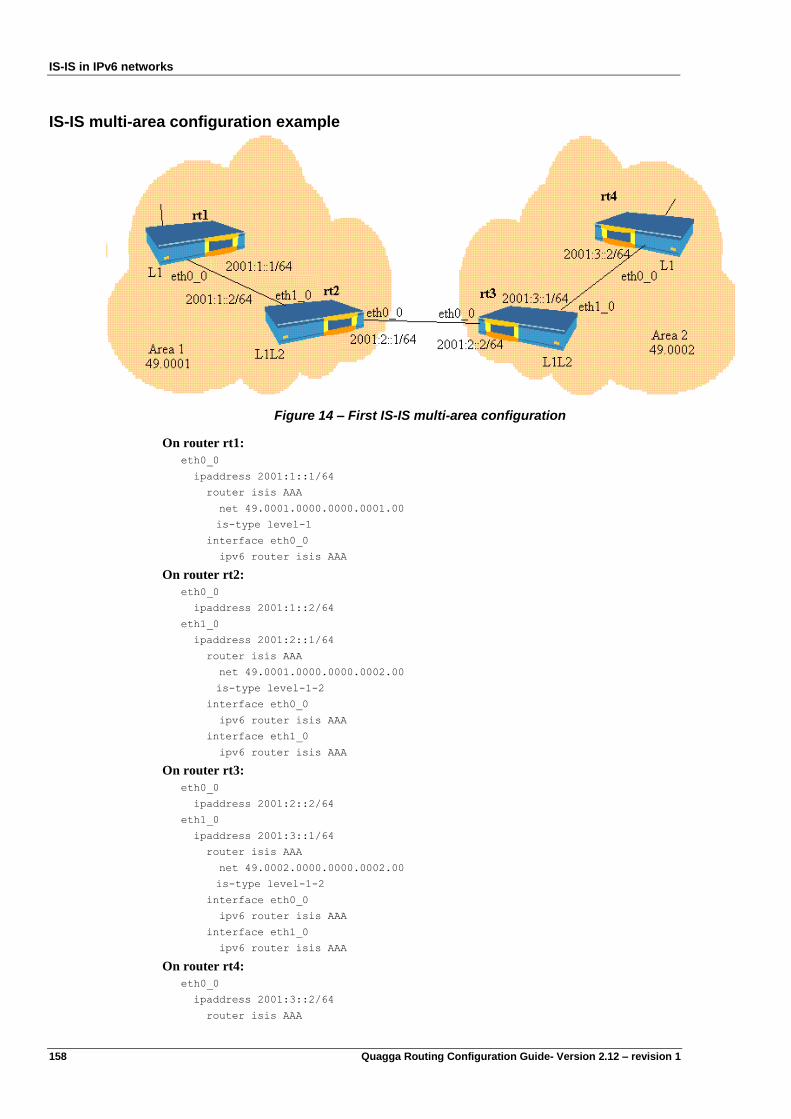
IS-IS in IPv6 networks
158 Quagga Routing Configuration Guide- Version 2.12 – revision 1
IS-IS multi-area configuration example
Figure 14 – First IS-IS multi-area configuration
On router rt1:
eth0_0
ipaddress 2001:1::1/64
router isis AAA
net 49.0001.0000.0000.0001.00
is-type level-1
interface eth0_0
ipv6 router isis AAA
On router rt2:
eth0_0
ipaddress 2001:1::2/64
eth1_0
ipaddress 2001:2::1/64
router isis AAA
net 49.0001.0000.0000.0002.00
is-type level-1-2
interface eth0_0
ipv6 router isis AAA
interface eth1_0
ipv6 router isis AAA
On router rt3:
eth0_0
ipaddress 2001:2::2/64
eth1_0
ipaddress 2001:3::1/64
router isis AAA
net 49.0002.0000.0000.0002.00
is-type level-1-2
interface eth0_0
ipv6 router isis AAA
interface eth1_0
ipv6 router isis AAA
On router rt4:
eth0_0
ipaddress 2001:3::2/64
router isis AAA
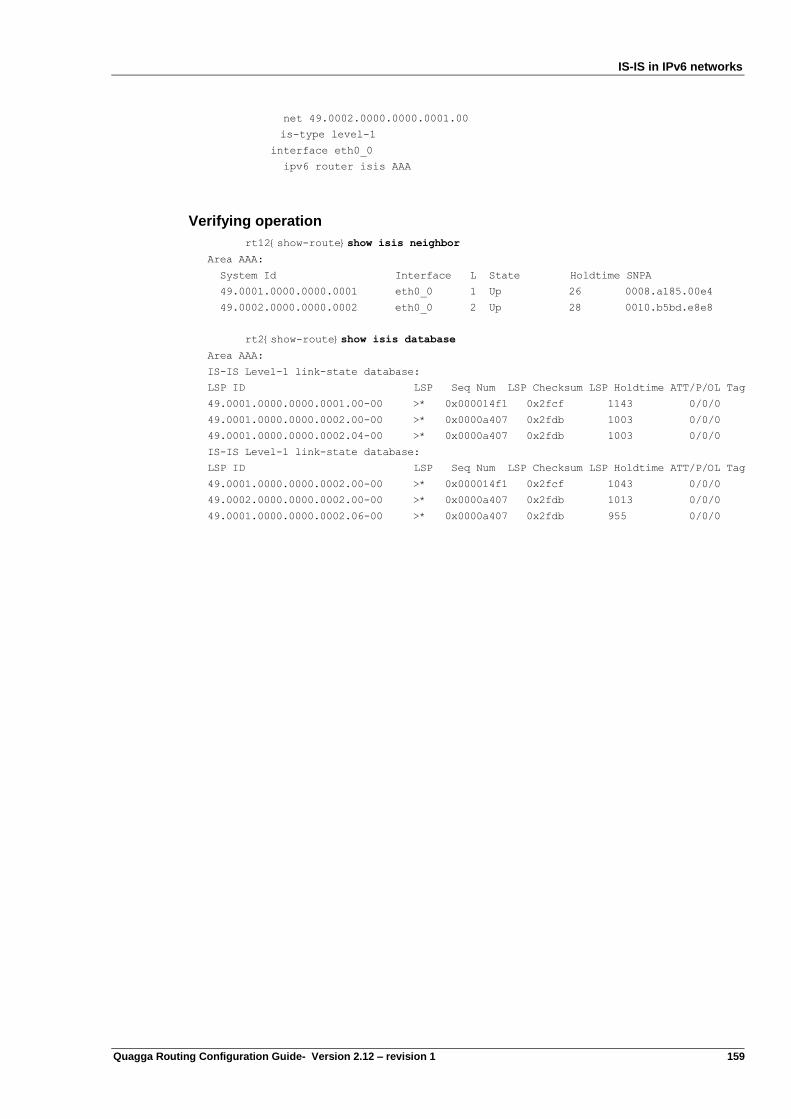
IS-IS in IPv6 networks
Quagga Routing Configuration Guide- Version 2.12 – revision 1 159
net 49.0002.0000.0000.0001.00
is-type level-1
interface eth0_0
ipv6 router isis AAA
Verifying operation
rt12{show-route}show isis neighbor
Area AAA:
System Id Interface L State Holdtime SNPA
49.0001.0000.0000.0001 eth0_0 1 Up 26 0008.a185.00e4
49.0002.0000.0000.0002 eth0_0 2 Up 28 0010.b5bd.e8e8
rt2{show-route}show isis database
Area AAA:
IS-IS Level-1 link-state database:
LSP ID LSP Seq Num LSP Checksum LSP Holdtime ATT/P/OL Tag
49.0001.0000.0000.0001.00-00 >* 0x000014f1 0x2fcf 1143 0/0/0
49.0001.0000.0000.0002.00-00 >* 0x0000a407 0x2fdb 1003 0/0/0
49.0001.0000.0000.0002.04-00 >* 0x0000a407 0x2fdb 1003 0/0/0
IS-IS Level-1 link-state database:
LSP ID LSP Seq Num LSP Checksum LSP Holdtime ATT/P/OL Tag
49.0001.0000.0000.0002.00-00 >* 0x000014f1 0x2fcf 1043 0/0/0
49.0002.0000.0000.0002.00-00 >* 0x0000a407 0x2fdb 1013 0/0/0
49.0001.0000.0000.0002.06-00 >* 0x0000a407 0x2fdb 955 0/0/0

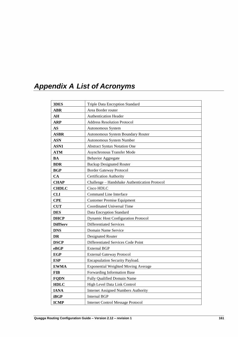
Quagga Routing Configuration Guide – Version 2.12 – revision 1 161
Appendix A List of Acronyms
3DES Triple Data Encryption Standard
ABR Area Border router
AH Authentication Header
ARP Address Resolution Protocol
AS Autonomous System
ASBR Autonomous System Boundary Router
ASN Autonomous System Number
ASN1 Abstract Syntax Notation One
ATM Asynchronous Transfer Mode
BA Behavior Aggregate
BDR Backup Designated Router
BGP Border Gateway Protocol
CA Certification Authority
CHAP Challenge – Handshake Authentication Protocol
CHDLC Cisco HDLC
CLI Command Line Interface
CPE Customer Premise Equipment
CUT Coordinated Universal Time
DES Data Encryption Standard
DHCP Dynamic Host Configuration Protocol
DiffServ Differentiated Services
DNS Domain Name Service
DR Designated Router
DSCP Differentiated Services Code Point
eBGP External BGP
EGP External Gateway Protocol
ESP Encapsulation Security Payload.
EWMA Exponential Weighted Moving Average
FIB Forwarding Information Base
FQDN Fully Qualified Domain Name
HDLC High Level Data Link Control
IANA Internet Assigned Numbers Authority
iBGP Internal BGP
ICMP Internet Control Message Protocol
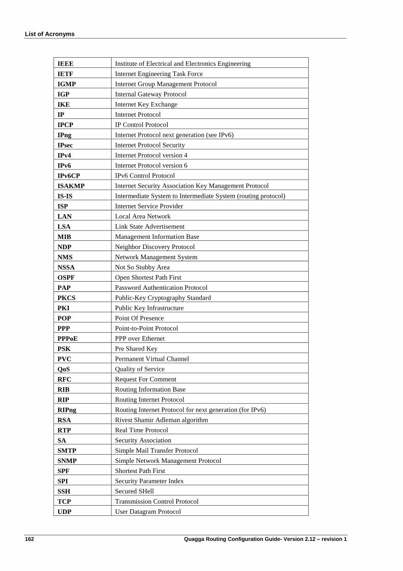
List of Acronyms
162 Quagga Routing Configuration Guide- Version 2.12 – revision 1
IEEE Institute of Electrical and Electronics Engineering
IETF Internet Engineering Task Force
IGMP Internet Group Management Protocol
IGP Internal Gateway Protocol
IKE Internet Key Exchange
IP Internet Protocol
IPCP IP Control Protocol
IPng Internet Protocol next generation (see IPv6)
IPsec Internet Protocol Security
IPv4 Internet Protocol version 4
IPv6 Internet Protocol version 6
IPv6CP IPv6 Control Protocol
ISAKMP Internet Security Association Key Management Protocol
IS-IS Intermediate System to Intermediate System (routing protocol)
ISP Internet Service Provider
LAN Local Area Network
LSA Link State Advertisement
MIB Management Information Base
NDP Neighbor Discovery Protocol
NMS Network Management System
NSSA Not So Stubby Area
OSPF Open Shortest Path First
PAP Password Authentication Protocol
PKCS Public-Key Cryptography Standard
PKI Public Key Infrastructure
POP Point Of Presence
PPP Point-to-Point Protocol
PPPoE PPP over Ethernet
PSK Pre Shared Key
PVC Permanent Virtual Channel
QoS Quality of Service
RFC Request For Comment
RIB Routing Information Base
RIP Routing Internet Protocol
RIPng Routing Internet Protocol for next generation (for IPv6)
RSA Rivest Shamir Adleman algorithm
RTP Real Time Protocol
SA Security Association
SMTP Simple Mail Transfer Protocol
SNMP Simple Network Management Protocol
SPF Shortest Path First
SPI Security Parameter Index
SSH Secured SHell
TCP Transmission Control Protocol
UDP User Datagram Protocol
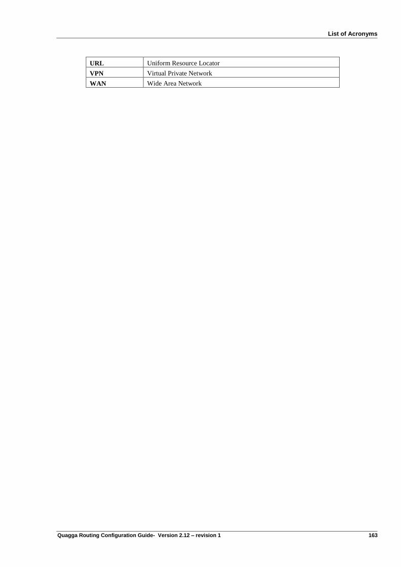
List of Acronyms
Quagga Routing Configuration Guide- Version 2.12 – revision 1 163
URL Uniform Resource Locator
VPN Virtual Private Network
WAN Wide Area Network