Embed Size (px)
Citation preview
SNR
Quadruple Tank Process Using PLC
SNR
Sponsored By: Department of Instrumentation & Control, College Of Engineering, Pune.
Presented By: 1. Sagar Mirgane 2. Nelson Savio Suresh 3. Rajnikant Rakesh
Guide: Mr R.D. Kamble
SNR
To control the levels of a quadruple tank using initially PLC and then using a microcontroller.
The two inputs to this process is pump1 and pump2.
The output to be monitored are the tank levels.
Introduction
SNR
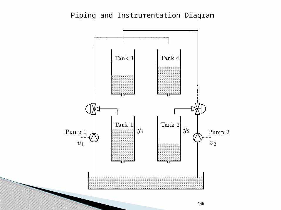
Piping and Instrumentation Diagram
SNR
The main intention is to control the levels of the tanks(1&2) by controlling the pumps 1 and 2.
The point to be noted is that when the speed of one pump is changed the levels of all the tanks are affected, as the tanks are interconnected.
Project Introduction
SNR
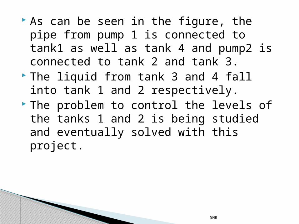
As can be seen in the figure, the pipe from pump 1 is connected to tank1 as well as tank 4 and pump2 is connected to tank 2 and tank 3.
The liquid from tank 3 and 4 fall into tank 1 and 2 respectively.
The problem to control the levels of the tanks 1 and 2 is being studied and eventually solved with this project.
SNR
PLC: Allen Bradley PLC Software:RS LOGIX5000 Microcontroller: Atmega 16L
Specification
SNR
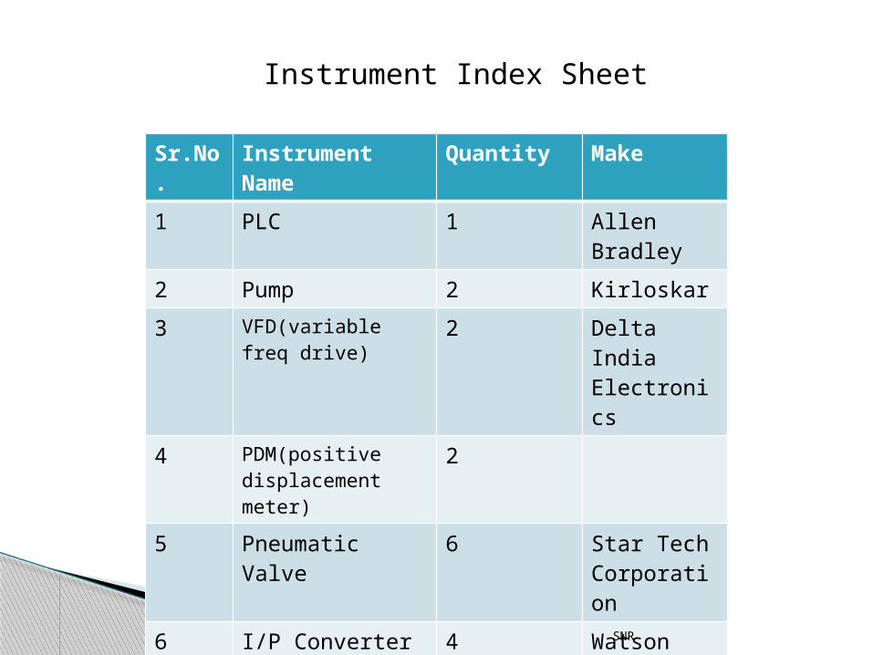
Sr.No.
Instrument Name
Quantity Make
1 PLC 1 Allen Bradley
2 Pump 2 Kirloskar
3 VFD(variable freq drive)
2 Delta India Electronics
4 PDM(positive displacement meter)
2
5 Pneumatic Valve 6 Star Tech Corporation
6 I/P Converter 4 Watson Smith
7 Capacitive Level Sensor
4
Instrument Index Sheet
SNR
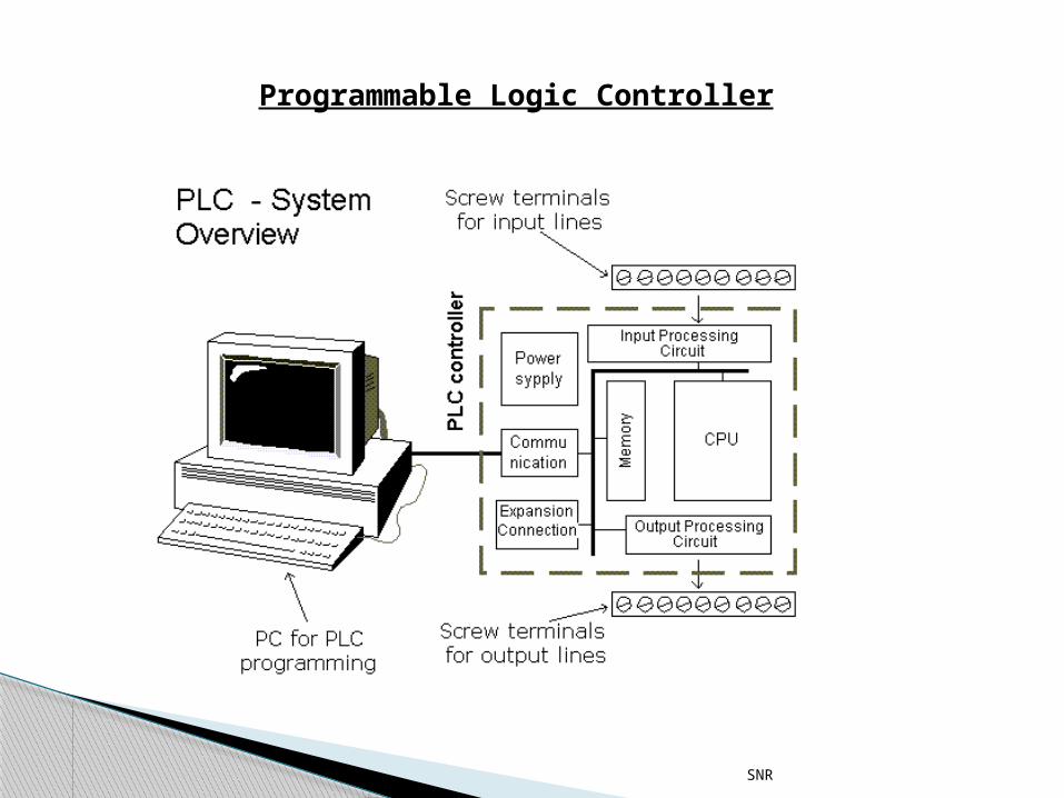
Programmable Logic Controller
SNR
•In automated systems PLC is regarded as the heart of control systems.
•With a controlled stored program in execution the PLC constantly monitors the state of the system through the feedback signals. It will then based on the program logic to determine the course of action to be taken at the field output devices.
•The PLC may be used to do a simple or repetitive task, or a few of them may be interconnected together through other host controllers or host computers by communication interfaces.
•A PLC consists of Central Processing Unit (CPU) containing an application program and input and output interface modules, which are directly, connected to the field I/O devices. The program controls the PLC so that when the signal from an input device turns ON the appropriate response is made. The response normally involves turning ON an output signal to some sort of output devices
SNR
Central Processing Unit (CPU)
The CPU is a microprocessor that co-ordinates the activities of the PLC system. It execute the program, processes I/O signals & communicates with external devices
SNR
Memory devices
There are four types of memory unit. It is the area that hold the operating system and user memory. The operating system is actually a software that co-ordinates the PLC.
Ladder program, timer & counter are stored in user memory.
SNR
Input Devices Push button, toggle switches & keypads which
form the basic man-machine interface are type of manual input devices.
On the other hand for the detection of work piece, monitoring of moving mechanism, checking on pressure or liquid level and many others, the PLC will have to tap the signal from the specific automatic sensing devices like proximity switches, limit switches, photoelectric sensor, level sensor and so on. These input devices are interfaced on PLC through various types of PLC input module.
SNR
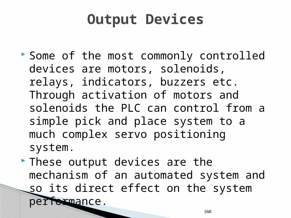
Some of the most commonly controlled devices are motors, solenoids, relays, indicators, buzzers etc. Through activation of motors and solenoids the PLC can control from a simple pick and place system to a much complex servo positioning system.
These output devices are the mechanism of an automated system and so its direct effect on the system performance.
Output Devices
SNR
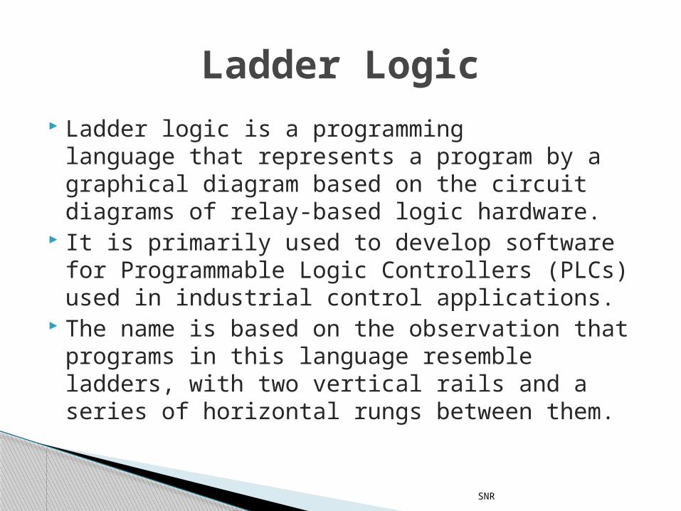
Ladder logic is a programming language that represents a program by a graphical diagram based on the circuit diagrams of relay-based logic hardware.
It is primarily used to develop software for Programmable Logic Controllers (PLCs) used in industrial control applications.
The name is based on the observation that programs in this language resemble ladders, with two vertical rails and a series of horizontal rungs between them.
Ladder Logic
SNR
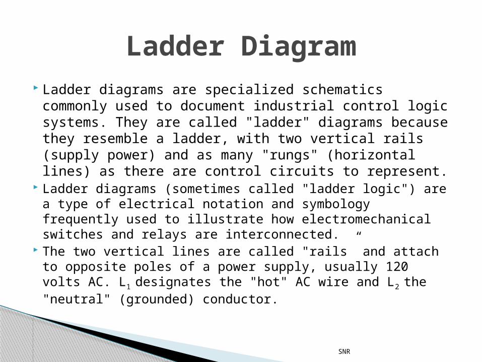
Ladder diagrams are specialized schematics commonly used to document industrial control logic systems. They are called "ladder" diagrams because they resemble a ladder, with two vertical rails (supply power) and as many "rungs" (horizontal lines) as there are control circuits to represent.
Ladder diagrams (sometimes called "ladder logic") are a type of electrical notation and symbology frequently used to illustrate how electromechanical switches and relays are interconnected.
The two vertical lines are called "rails” and attach to opposite poles of a power supply, usually 120 volts AC. L1
designates the "hot" AC wire and L2 the "neutral" (grounded) conductor.
Ladder Diagram
SNR
SNR
A variable-frequency drive (VFD) is a system for controlling the rotational speed of an alternating current (AC) electric motor by controlling the frequency of the electrical power supplied to the motor.
A variable frequency drive is a specific type of adjustable-speed drive.
Variable-frequency drives are also known as adjustable-frequency drives (AFD), variable-speed drives (VSD), AC drives, micro drives or inverter drives.
Variable Frequency Drive
SNR
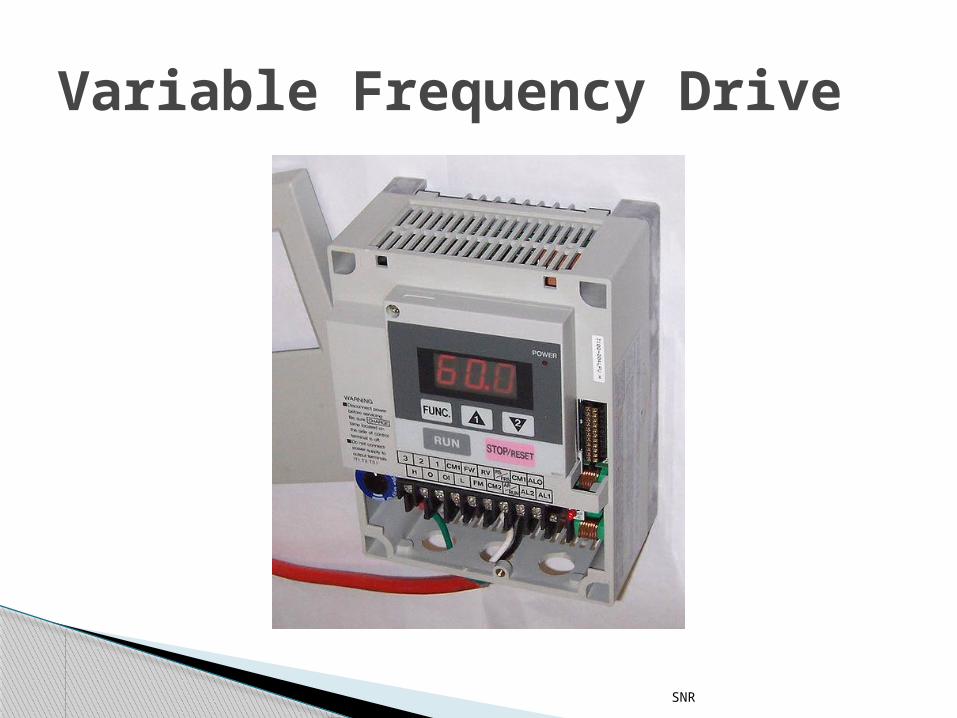
Variable Frequency Drive
SNR
A positive displacement meter is a type of flow meter that requires the fluid being measured to mechanically displace components in the meter in order for any fluid flow to occur. Positive displacement (PD) flow meters make volumetric flow measurements taking finite increments or volumes of the fluid. A basic analogy would be holding a bucket below a tap, filling it to a set level, then quickly replacing it with another bucket and timing the rate at which the buckets are filled (or the total number of buckets for the “totalized” flow).
Positive Displacement Meter
SNR
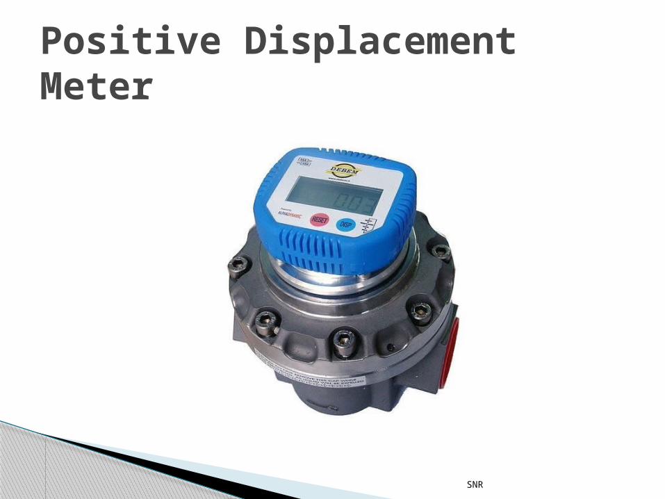
Positive Displacement Meter
SNR
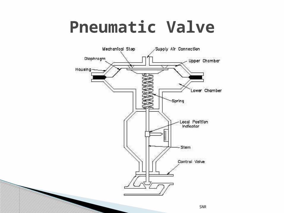
Pneumatic Valve
SNR
When pressure is applied on the diaphram then the diaphram pushes a rod that it is connected to with a spring assembly.
We are using two types of pneumatic valves.
The on-off valve and the modulating valve.
Pneumatic Valve
SNR
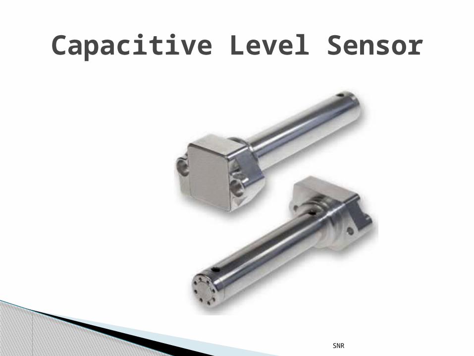
Capacitance level sensors excel in sensing the presence of a wide variety of solids, aqueous and organic liquids, and slurries.
Appropriate choice of probe materials reduces or eliminates problems caused by abrasion and corrosion
Technically speaking, the capacitance is directly proportional to the surface area of the objects and the dielectric constant of the material between them, and inversely proportional to the distance between them
Capacitive Level Sensor
SNR
Capacitive Level Sensor
SNR
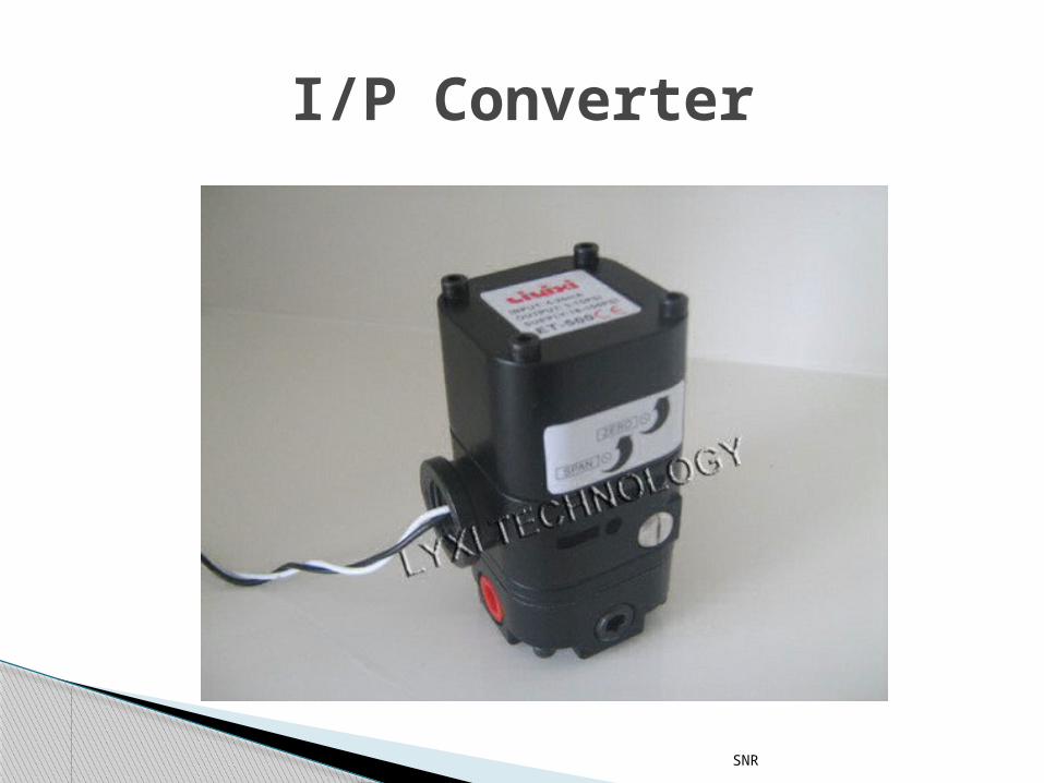
A “current to pressure” converter (I/P) converts an analog signal (4 to 20 mA) to a proportional linear pneumatic output (3 to 15 psig). Its purpose is to translate the analog output from a control system into a precise, repeatable pressure value to control pneumatic actuators/operators, pneumatic valves, dampers, vanes, etc.
I/P Converter
SNR
I/P Converter
SNR
Project Description
SNR
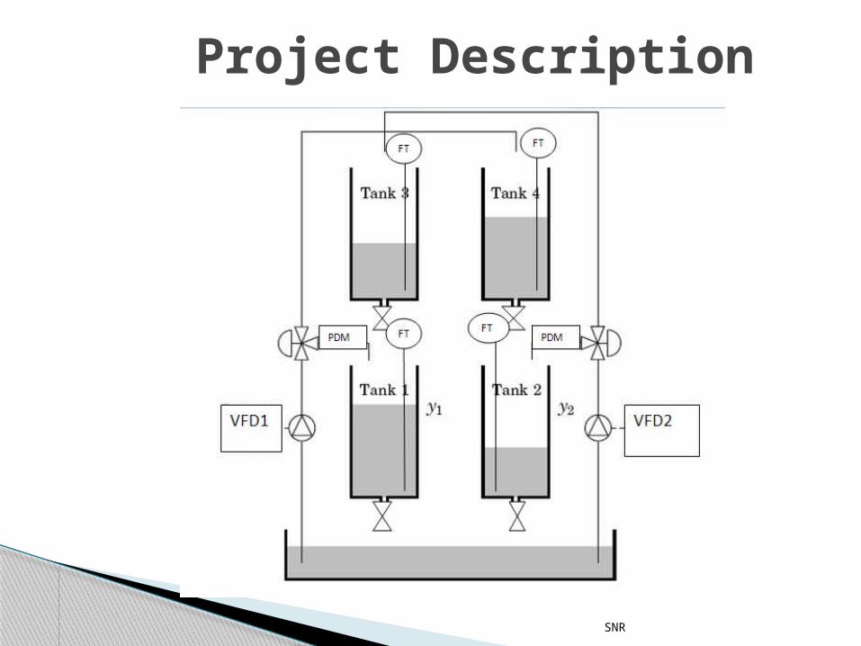
As can be seen the VFDs are connected to the pumps, so that we can control the speed of the pumps.
We have also connected a PDM to keep a tab on the amount of liquid that goes into the tank 1 and tank 2.
The two 3- way pneumatic valves are governed by a quantity ˠ.
The value of this quantity varies from 0 to 1. When this value is 0 then the liquid from
pump is directed directly to tank 1 and 2 and when it is 1 it is directed to 3 and 4 respectively.
SNR
The capacitive level sensors continuously measure the levels of all the tanks and are the quantity we monitor for the further functioning of the tank process.
Consider the monitoring of level of tank 1

SNR
THANK YOU!!!