Embed Size (px)
Citation preview
Ah^Am^Ht* TECHNICAL
LIBRARY: AD
TECHNICAL REPORT ARLCB-TR-80044
QUADRATIC AND CUBIC TRANSITION ELEMENTS
M, A, Hussain J. D. Vasilakis S, L, Pu
November 1980
US ARMY ARMAMENT RESEARCH AND DEVELOPMENT COMMAND LARGE CALIBER WEAPON SYSTEMS LABORATORY
BENET WEAPONS LABORATORY
WATERVLIET, N. Y. 12189
AMCMS No. 611102H600011
DA Project No. 1L161102AH60
PRON No. 1A0215601A1A
DTIC QUALTTY INSPECTBD 3
APPROVED FOR PUBLIC RELEASE; DISTRIBUTION UNLIMITED
DISCLAIMER
The findings in this report are not to be construed as an official
Department of the Army position unless so designated by other author-
ized documents.
The use of trade name(s) and/or manufacturer(s) does not consti-
tute an official indorsement or approval.
DISPOSITION
Destroy this report when it is no longer needed. Do not return it
to the originator.
SECURITY CLASSIFICATION OF THIS PAGE (When Dmlm Enfnd)
REPORT DOCUMENTATION PAGE 1. REPORT NUMBER
ARLCB-TR-80044
2. GOVT ACCESSION NO
4. T\TLE (mnd Subtitle)
QUADRATIC AND CUBIC TRANSITION ELEMENTS
'• AUTHORO)
M. A, Hussaln J. Di Vasllakis S. L. Pu
>■ PERFORMING ORGANIZATION NAME AND ADDRESS
Benet Weapons Laboratory Watervllet Arsenal, Watervliet, NY 12189 DRDAR-LCB-TL
11. CONTROLLING OFFICE NAME AND ADDRESS
US Army Armament Research and Development Command Large Caliber Weapon Systems Laboratory Dover, NJ 07801
14. MONITORING AGENCY NAME ft ADDRESSf//dl«.r«n» Item Controlling OUIct)
IS. DISTRIBUTION STATEMENT (al thim R»port)
READ mSTRUCTIONS BEFORE COMPLETING FORM
3. RECIPIENT'S CATALOG NUMBER
5. TYPE OF REPORT ft PERIOD COVERED
6. PERFORMING ORG. REPORT NUMBER
8. CONTRACT OR GRANT NUMBER^,)
10. PROGRAM ELEMENT, PROJECT, TASK AREA ft WORK UNIT NUMBERS
AMCMS No. 611102H600011 DA Project No. 1L161102AH60 PRON No. 1A0215601A1A 12. REPORT DATE
November 1980 13. NUMBER OF PAGES
19 IB. SECURITY CLASS, (ot (Ma rmport)
UNCLASSIFIED 18*. DECLASSIFI CATION/DOWN GRADING
SCHEDULE
Approved for public release; distribution unlimited.
17. DISTRIBUTION STATEMENT (of th» mbtlrmct mnltrmd In Black 30, H dliltfnt horn Report)
U. tUW-EMMTARY NOTM Presented at 26th Conference of Army Mathematicians, Cold Regions Research and Engineering Lab, Hanover, New Hampshire, 10-12 June 1980. Submitted for publication in International Journal for Numerical Methods in Engineering.
19. KEY WORDS (Continue on revetee elde it neceemmry and identity by block number)
Finite Elements Transition Elements Stress Intensity Factors
M> AMTWACT fOmBmm me frar— ai* It mmmmmm —t tdentitr fcy block nuwttj
Based on the investigations of Barsoum.1 Henshell and Shaw,2 quarterpolnt quadratic elements have been successfully used as crack tip elements in fracture mechanics. This concept of singular element was extended to cubic isoparametric elements.-^ Recently It was discovered by Lynn and Ingraffea^ that under special configuration, transitional elements improve the accuracy of stress intensity factor computations. In this report, we have obtained
(CONT'D ON REVERSE)
DD , IST,, 1473 EDtTtON OF • NOV SS IS OBSOLETE UNCLASSIFIED
SECimiTY CLJUSTFICATIOK OF THIS PAGE f Data Entered)

SECURITY CLASSIFICATION OF THIS PAOEfWun Data Enl.-.d;
20. ABSTRACT (Cont'd)
the location of mid-side nodes of these transitional elements for the quadratic as well as cubic elements. The cubic transitional elements were used for the double-edge crack problem, and it was found that there was improvement in accuracy for a configuration which consisted only of singular and transitional elements. However, for a well laid out grid, the improvement was only marginal.
SCCURITY CLASSIFICATION OF THIS PAOE(Wh»n Data Bnttrta)
TABLE OF CONTENTS
INTRODUCTION
SECTION I
SECTION II
SECTION III
SECTION IV
CONCLUSIONS
REFERENCES
APPENDIX A
TABLES
I. STRESS INTENSITY FACTOR AND PERCENTAGE ERROR FOR A DOUBLE- EDGE CRACKED PLATE USING 12-NODE COLLAPSED SINGULAR ELEMENTS WITH AND WITHOUT TRANSITION ELEMENTS. FINITE ELEMENT IDEALIZATION OF FIGURE 3.
II. STRESS INTENSITY FACTOR AND PERCENTAGE ERROR FOR A DOUBLE- EDGE CRACKED PLATE USING 12-NODE COLLAPSED SINGULAR ELEMENTS WITH AND WITHOUT TRANSITION ELEMENTS. FINITE ELEMENT IDEALIZATION OF FIGURE 4.
LIST OF ILLUSTRATIONS
1. Quadratic quadrilateral Isoparametric element as transition element.
2. Cubic quadrilateral Isoparametric element as transition element.
3. An Idealization for a quarter of a double-edge cracked plate.
A. A similar Idealization used In Reference 4 for a quarter of a double-edge cracked plate.
Page
1
2
5
8
9
12
14
A-l
11
11
10
13
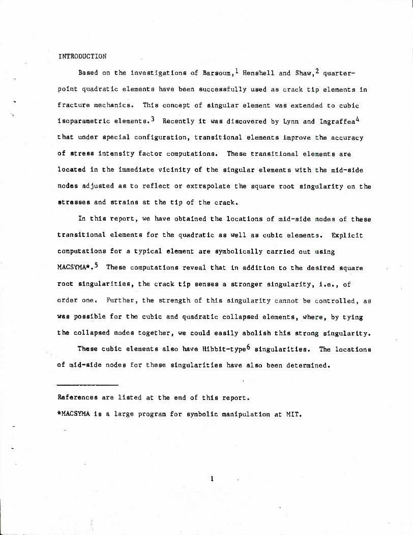
INTRODUCTION
Based on the investigations of Barsoum,! Henshell and Shaw,2 quarter-
point quadratic elements have been successfully used as crack tip elements In
fracture mechanics. This concept of singular element was extended to cubic
Isoparametric elements.3 Recently it was discovered by Lynn and Ingraffea^
that under special configuration, transitional elements Improve the accuracy
of stress intensity factor computations. These transitional elements are
located in the Immediate vicinity of the singular elements with the mid-side
nodes adjusted as to reflect or extrapolate the square root singularity on the
stresses and strains at the tip of the crack.
In this report, we have obtained the locations of mid-side nodes of these
transitional elements for the quadratic as well as cubic elements. Explicit
computations for a typical element are symbolically carried out using
MACSYMA*.^ These computations reveal that in addition to the desired square
root singularities, the crack tip senses a stronger singularity, i.e., of
order one. Further, the strength of this singularity cannot be controlled, as
was possible for the cubic and quadratic collapsed elements, where, by tying
the collapsed nodes together, we could easily abolish this strong singularity.
These cubic elements also have Hlbbit-type^ singularities. The locations
of mid-side nodes for these singularities have also been determined.
References are listed at the end of this report.
*MACSYMA is a large program for symbolic manipulation at MIT.
The cubic transitional, elements were used for a double-edge crack prob-
lem, and It was found that there was Improvement In accuracy for a configura-
tion which consisted only of singular and transitional elements. However, for
a well laid out grid, the Improvement was only marginal. MACSYMA has proved
to be an indispensable tool for the present Investigation.
SECTION I
Consider a quadratic quadrilateral isoparametric element,
8 8 x - I NiXt , y - I %¥! (1)
i-l 1-1
8 8 u - I NtUi , v - I NiV! (2)
1-1 1-1
where N^ are the shape functions of 'Serendipity* family,6 and are given by,
CORNER 1 NODES : Nl " 7 (1-0(1-TI)(-5-TI-1) , etc. (3)
A
MID-SIDE I . NODES : N5 " * (l-Cz)(l-n) , etc. (4)
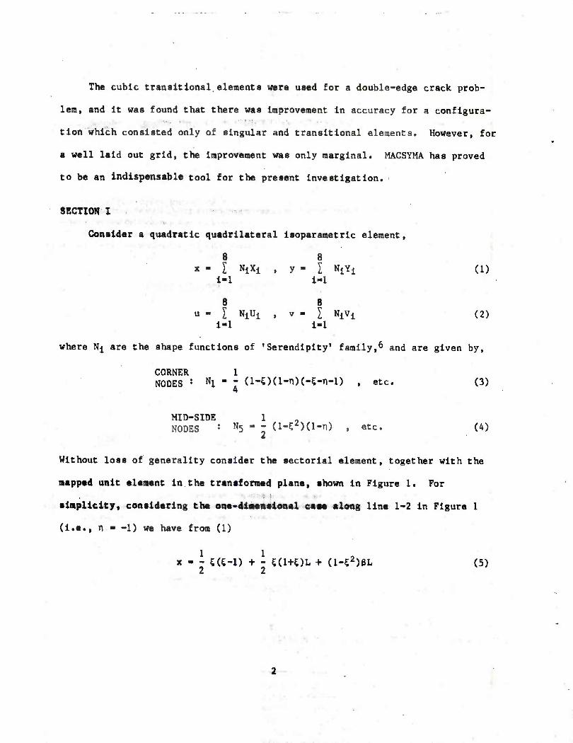
Without loss of generality consider the sectorial element, together with the
mapped unit element in the transformed plane, shown in Figure 1. For
simplicity, considering the one-dimensional case along line 1-2 In Figure 1
(i.e., n ■ -1) we have from (1)
x - - 5(5-1) + - 5(l+OL + (l-C2)fJL (5) 2 2
TRANSITION ELEMENT
(Lcosa,LsinQ)
(1,0) ((3L,0)
CD © SINGULAR ELEMENT
(L,0)
2
0 (-in) SINGULAR
LINE ©
* (i.-D
©
FIGURE I. QUADRATIC QUADRILATERAL ISOPARAMETRIC
ELEMENT AS TRANSITION ELEMENT
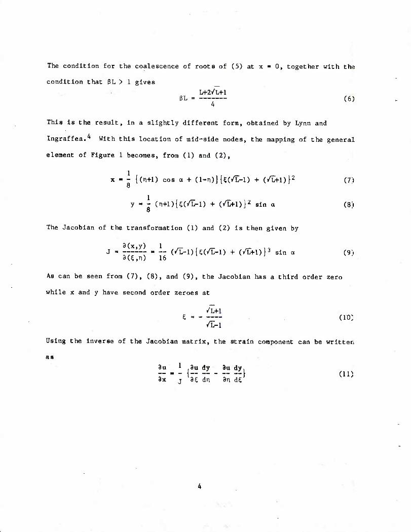
The condition for the coalescence of roots of (5) at x » 0, together with the
condition that 3L > 1 gives
W-2/L+1 3L (6)
4
This is the result, in a slightly different form, obtained by Lynn and
Ingraffea.^ With this location of mid-side nodes, the mapping of the general
element of Figure 1 becomes, from (1) and (2),
x - - {(n+1) cos a + (l-n)}U(/L-l) + (/L+l)}2 (7) 8
y - - (n+l){C(/L-l) + (/L+l)>2 sin a (8> 8
The Jacobian of the transformation (1) and (2) is then given by
j = 1__ =. __ (/I-Dl^/L-l) + (/L+l)}3 sin a (9~i 9(?,n) 16
As can be seen from (7), (8), and (9), the Jacobian has a third order zero
while x and y have second order zeroes at
•L+l 5 do:
•L-I
Using the inverse of the Jacobian matrix, the strain component can be written
as
3u ^ 9u dy 3u dy,
3x " j H dn an dC
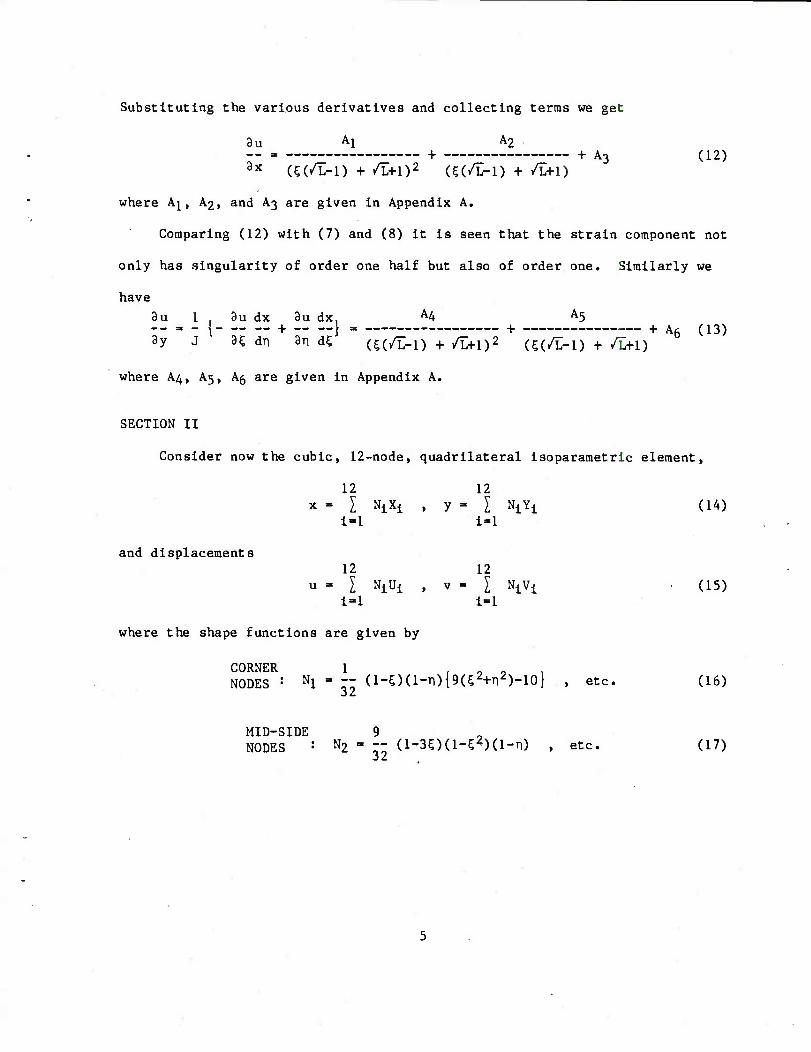
Substituting the various derivatives and collecting terms we get
8u Al A2 = + + A3 (12)
8x (?(/L-l) + /L+1)2 (C(/L-l) + /L+1)
where Aj, A2, and A3 are given in Appendix A.
Comparing (12) with (7) and (8) it is seen that the strain component not
only has singularity of order one half but also of order one. Similarly we
have 9u 1 . 9u dx 3u dx. A4 A5
8y J H dn 3n di (^(/L-I) + /L+1)2
U(/L-1) + /L+I) 6
where A4, A5, A5 are given in Appendix A.
SECTION II
Consider now the cubic, 12-node, quadrilateral isoparametric element,
12 12 x - I NjXi , y - I NiYj (14)
i-1 i=-l
and displacements 12 12
u = I NiUi , V - I NiVi (15) i-1 i-1
where the shape functions are given by
CORNER 1 r -> o 1 NODES : Nl ' 32 (1-OO-n){9(52+Tl2)-10} , etc. (16)
MID-SIDE 9 NODES - N2 = — (1-30(1-^)(1-TI) , etc. (17)
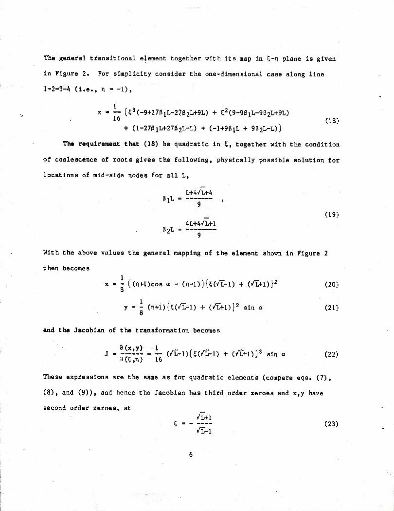
The general transitional element together with Its map In S-n plane Is given
in Figure 2. For simplicity consider the one-dimensional case along line
1-2-3-A (i.e., n - -1),
x - — [53(-9+27a1L-27e2L+9L) + C2(9-93iL-902L+9L)
16 (is;. + (1-2731L+2732L-L) + (-l+93iL + 932L-L))
The requirement that (18) be quadratic in K, together with the condition
of coalescence of roots gives the following, physically possible solution for
locations of mid-side nodes for all L,
>
(19)
llL.__ ,
4L+4/L+1 32L _
9
With the above values the general mapping of the element shown in Figure 2
then becomes
x - - (Ol+Dcos a - (n-l))U(/L-l) + (/L+l)}2 (20]. 8
y - - (n+l)U(/L-l) + (/W-l)}2 sin a (21) 8
and the Jacobian of the transformation becomes
3(x,y) 1 _ , _ _ ., J - - -- (/L-l)(5;(/L-l) + (/Lfl))3 sin a (22)
9(5,n) 16
These expressions are the same as for quadratic elements (compare eqs. (7),
(8), and (9)), and hence the Jacobian has third order zeroes and x,y have
second order zeroes, at
/W-l 5 - (23)
/L-l
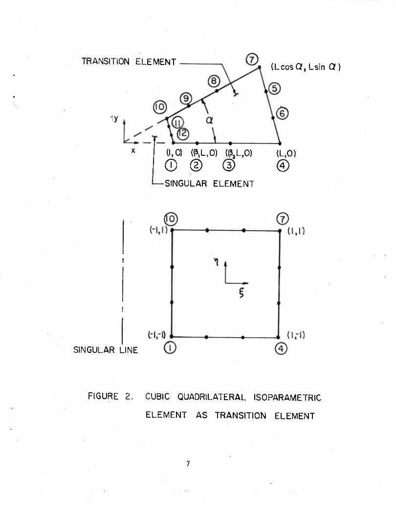
TRANSITION ELEMENT
iy
(Lcosa.Lsin Q)
L(l,0) (^L,0) (^L.O) (L,0)
© © (D © SINGULAR ELEMENT
SINGULAR LINE
FIGURE 2. CUBIC QUADRILATERAL ISOPARAMETRIC
ELEMENT AS TRANSITION ELEMENT
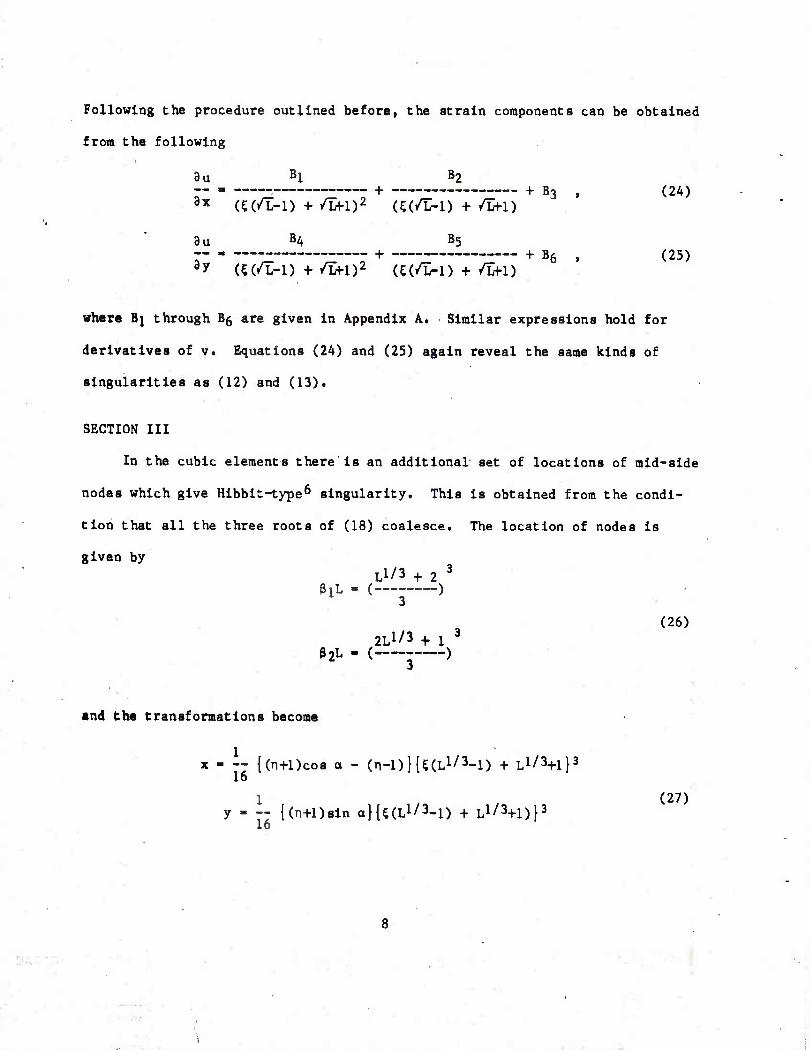
Following the procedure outlined before, the strain components can be obtained
from the following
au Bl B2 __ . . + + B3 , (2A) 3x (C(/L-l) + /Lfl)2 (5(/L-l) + /Lfl)
Bu B4 B5 _- . + + B6 | (25) ay «(/>!) + /Lfl)2 (€(•>!) + /U-l)
where Bj through B5 are given in Appendix A. Similar expressions hold for
derivatives of v. Equations (24) and (25) again reveal the same kinds of
singularities as (12) and (13).
SECTION HI
In the cubic elements there is an additional set of locations of mid-side
nodes which give Hibbit-type6 singularity. This is obtained from the condi-
tion that all the three roots of (18) coalesce. The location of nodes is
given by Ll/3 + 2 3
(26)
PlL - (---
2L1/3 + 1 3
fJ2L - ( )
and the transformations become
1 x - — {(n+l)cos o - (n-l)}U(Ll/3-l) + L1/^!}3
16 1 . (27)
y - — {(n+Dsin oHsa1'3-!) + L1/^!)}3
16
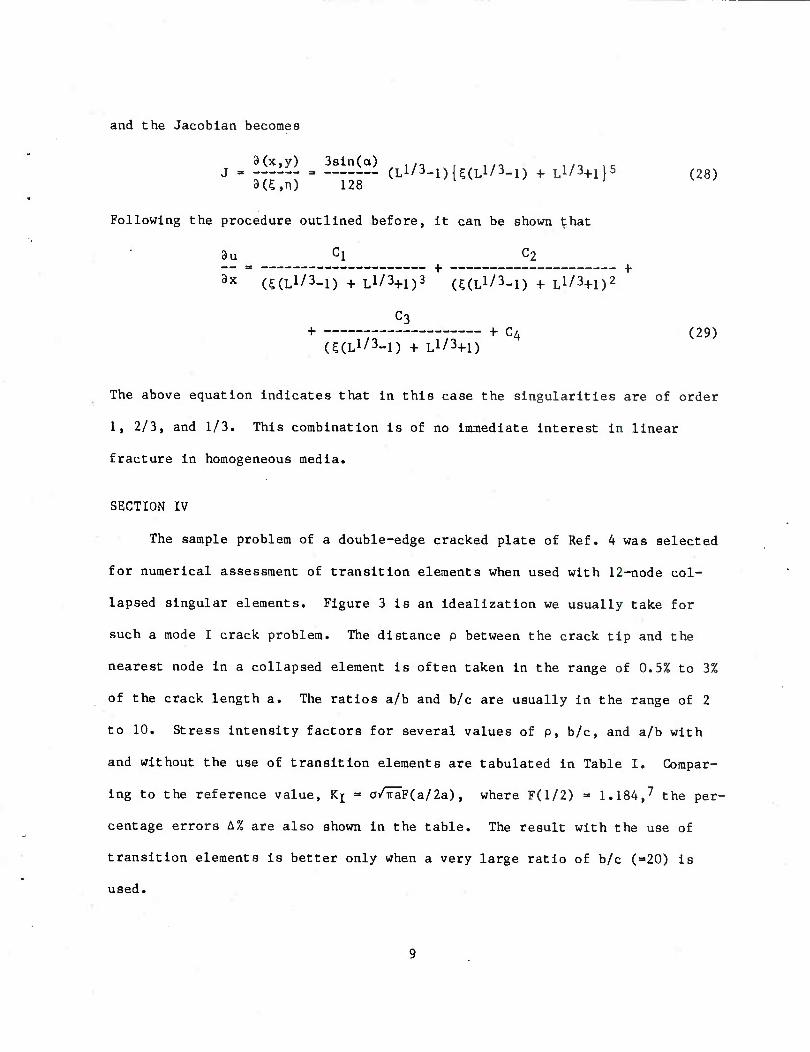
and the Jacobian becomes
8(x,y) 3sin(a) .,- ,,,,/, ,/a IK
8(5,n) 128
Following the procedure outlined before, it can be shown that
9u cl C2
3x = (SCJ/LD + Ll73+1)3 (gal/3-l)TLl/3+l)2 H
C3 + + C4 (29)
(^(L1/3-!) + L1/^!)
The above equation indicates that in this case the singularities are of order
1, 2/3, and 1/3. This combination is of no immediate interest in linear
fracture in homogeneous media.
SECTION IV
The sample problem of a double-edge cracked plate of Ref. 4 was selected
for numerical assessment of transition elements when used with 12-node col-
lapsed singular elements. Figure 3 is an idealization we usually take for
such a mode I crack problem. The distance p between the crack tip and the
nearest node in a collapsed element is often taken in the range of 0.5% to 3%
of the crack length a. The ratios a/b and b/c are usually in the range of 2
to 10. Stress intensity factors for several values of p, b/c, and a/b with
and without the use of transition elements are tabulated in Table I. Compar-
ing to the reference value, Kj ■ a/TraF(a/2a) , where F(l/2) » 1.184,7 the per-
centage errors A% are also shown in the table. The result with the use of
transition elements is better only when a very large ratio of b/c (=20) is
used.
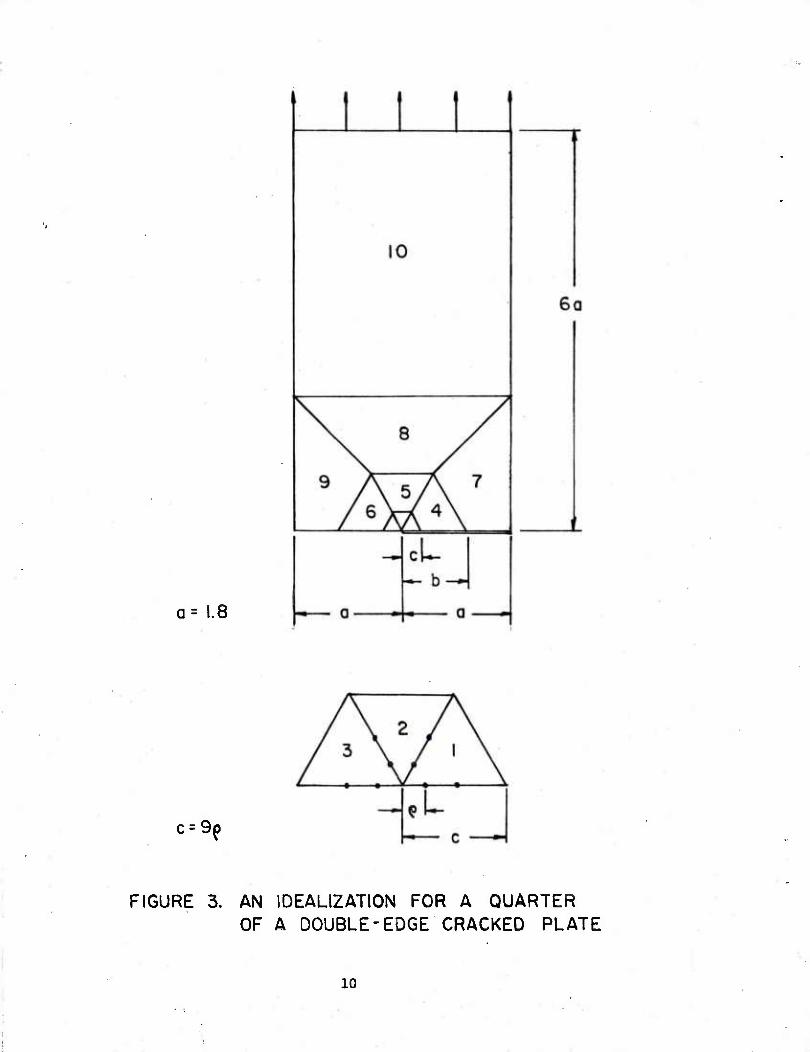
a= 1.8
c = 9()
FIGURE 3. AN IDEALIZATION FOR A QUARTER OF A DOUBLE-EDGE CRACKED PLATE
10
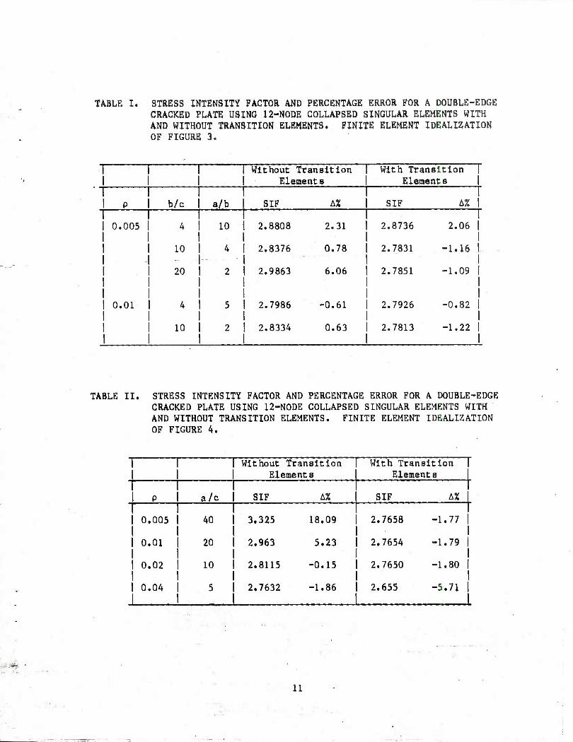
TABLE I. STRESS INTENSITY FACTOR AND PERCENTAGE ERROR FOR A DOUBLE-EDGE CRACKED PLATE USING 12-NODE COLLAPSED SINGULAR ELEMENTS WITH AND WITHOUT TRANSITION ELEMENTS. FINITE ELEMENT IDEALIZATION OF FIGURE 3.
! Without Transition Elements
With Transition I Element s
1 p b/c a/b SIF A% SIF A% |
I 0.005 4 10 2.8808 2.31 2.8736 2.06 1
10 4 2.8376 0.78 2.7831 -1.16 1
20 2 2.9863 6.06 2.7851 -1.09 |
0.01 4 5 2.7986 -0.61 2.7926 -0.82 |
10 2 2.8334 0.63 2.7813 -1.22 |
TABLE 11, STRESS INTENSITY FACTOR AND PERCENTAGE ERROR FOR A DOUBLE-EDGE CRACKED PLATE USING 12-NODE COLLAPSED SINGULAR ELEMENTS WITH AND WITHOUT TRANSITION ELEMENTS. FINITE ELEMENT IDEALIZATION OF FIGURE 4.
Without Transition Element s
With Transition Element s
p a/c SIF A% SIF 1
0.005 40 3.325 18.09 2.7658 -1.77 |
0.01 20 2.963 5.23 2.7654 -1.79 |
0.02 10 2.8115 -0.15 2.7650 -1.80 |
0.04 5 2.7632 -1.86 2.655 -5.71 |
11
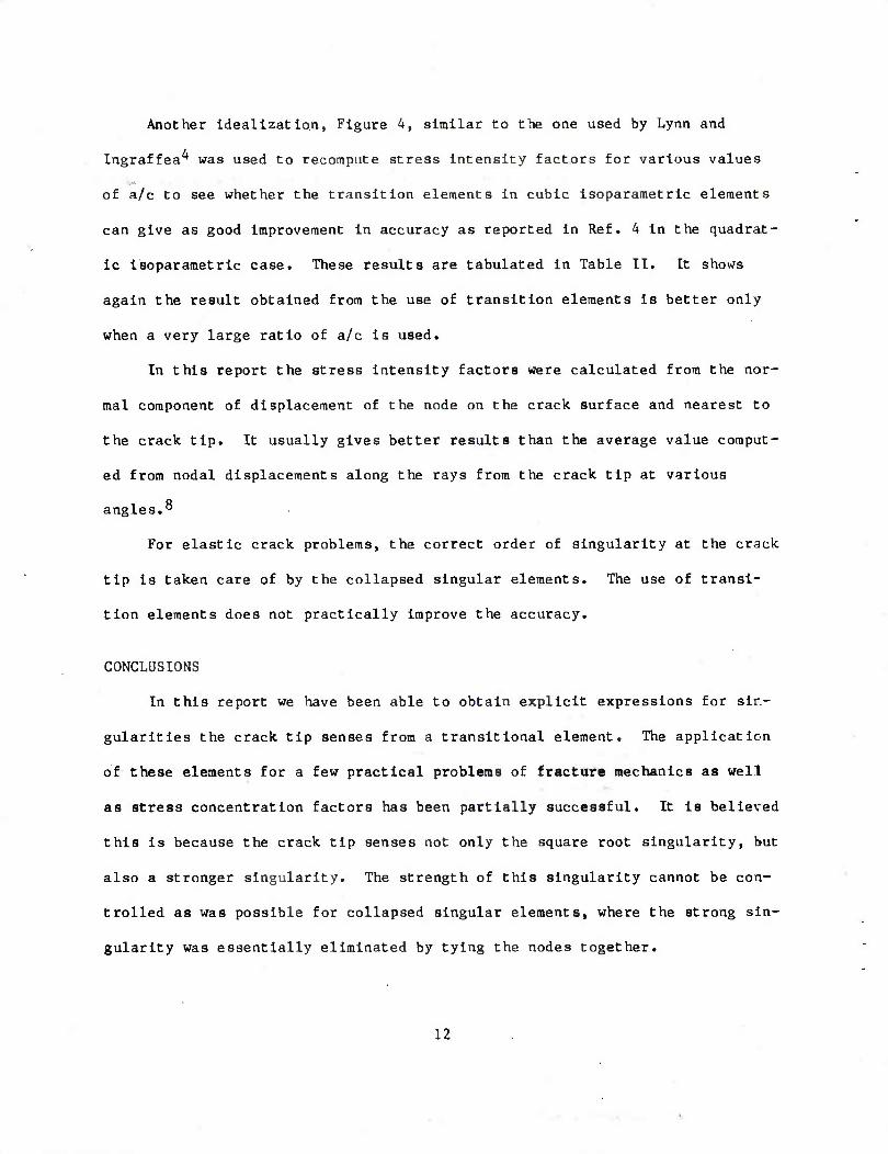
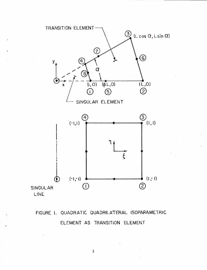
Another Idealization, Figure 4, similar to the one used by Lynn and
Ingraffea^ was used to recompute stress Intensity factors for various values
of a/c to see whether the transition elements In cubic isoparametric elements
can give as good improvement In accuracy as reported in Ref. 4 in the quadrat-
ic isoparametric case. These results are tabulated in Table II. It shows
again the result obtained from the use of transition elements is better only
when a very large ratio of a/c is used.
In this report the stress intensity factors were calculated from the nor-
mal component of displacement of the node on the crack surface and nearest to
the crack tip. It usually gives better results than the average value comput-
ed from nodal displacements along the rays from the crack tip at various
angles.°
For elastic crack problems, the correct order of singularity at the crack
tip is taken care of by the collapsed singular elements. The use of transi-
tion elements does not practically Improve the accuracy.
CONCLUSIONS
In this report we have been able to obtain explicit expressions for sin-
gularities the crack tip senses from a transitional element. The application
of these elements for a few practical problems of fracture mechanics as well
as stress concentration factors has been partially successful. It is believed
this is because the crack tip senses not only the square root singularity, but
also a stronger singularity. The strength of this singularity cannot be con-
trolled as was possible for collapsed singular elements, where the strong sin-
gularity was essentially eliminated by tying the nodes together.
12
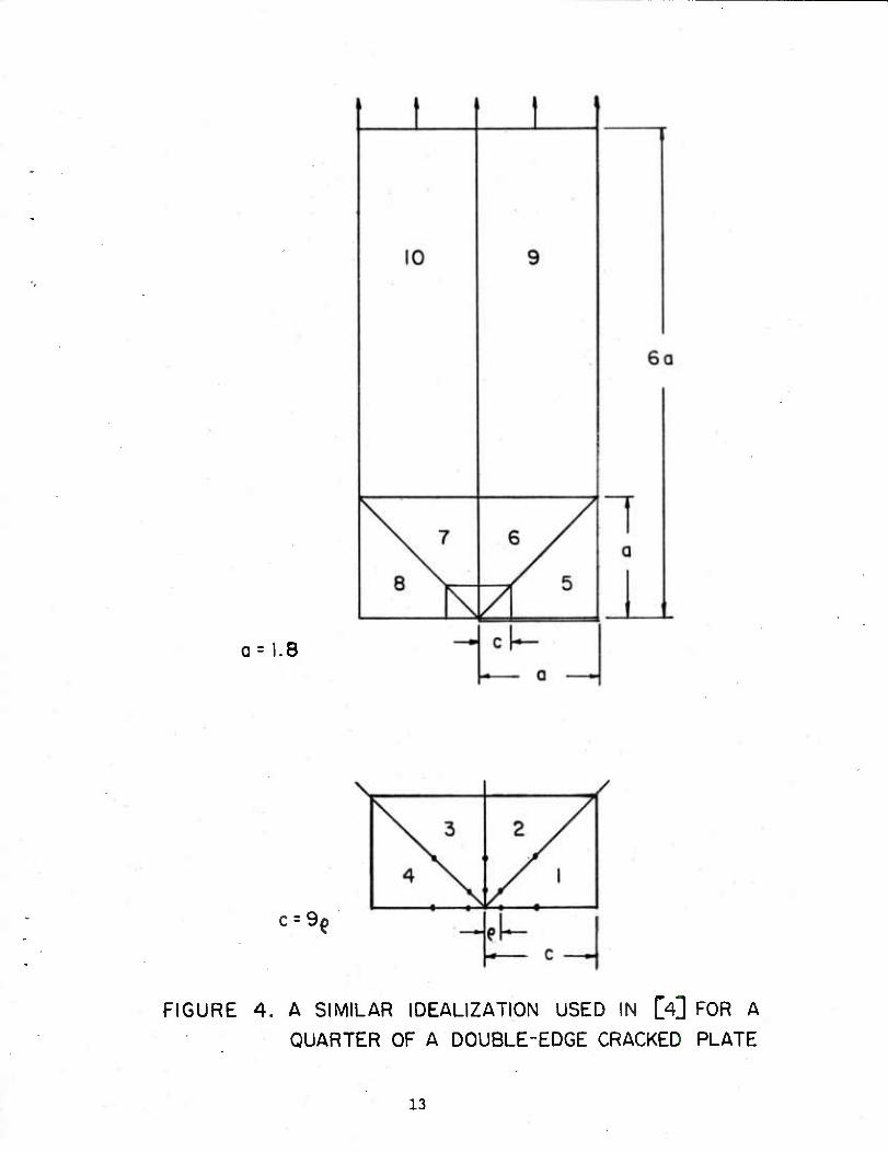
a= 1.8
c = 9i
FIGURE 4. A SIMILAR IDEALIZATION USED IN [4] FOR A QUARTER OF A DOUBLE-EDGE CRACKED PLATE
13
REFERENCES
1. Baraoum, Roshdy S,, "On the Use of Isoparametric Finite Elements in Linear
Fracture Mechanics," Int. J. Num. Meth. Engrg., Vol. 10, 1976, pp. 25-76.
2. Henahell, R. D. and Shaw, K. G., "Crack Tip Elements are Unnecessary,"
Int. J. Num. Meth. Engrg., Vol. 9, 1975, pp. 495-507.
3. Pu, S, L., Hussain, M. A., and Lorensen, W. E,, "The Collapsed Cubic
Isoparametric Element as a Singular Element for Crack Problems," Int. J.
Num. Meth. Engrg., Vol. 12, 1978, pp. 1727-1742.
4. Lynn, P. P., Ingraffea, A, R., "Transition Elements to be Used with
Quarter-Point Crack-Tip Elements," Int. J. Num. Meth. Engrg., Vol. 12,
1978, pp. 1031-1036.
5. "MACSYMA Reference Manual," The Mathlab Group, Laboratory for Computer
Science, MIT, Cambridge, MA.
6. Hibbit, H. D., "Some Properties of Singular Isoparametric Elements," Int.
J. Num. Meth. Engrg., Vol. 11, 1977, pp. 180-184.
7. Tada, H., Paris, P., and Irwin, G., The Stress Analysis of Cracks Hand-
book, Del Research Corp., 1973.
8. Pu, S. L., Hussain, M. A,, and Lorensen, W. E., "Collapsed 12-Node
Triangular Elements as Crack Tip Elements For Elastic Fracture," Technical
Report ARLCB-TR-77047, December 1977.
14
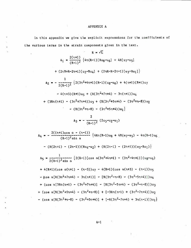
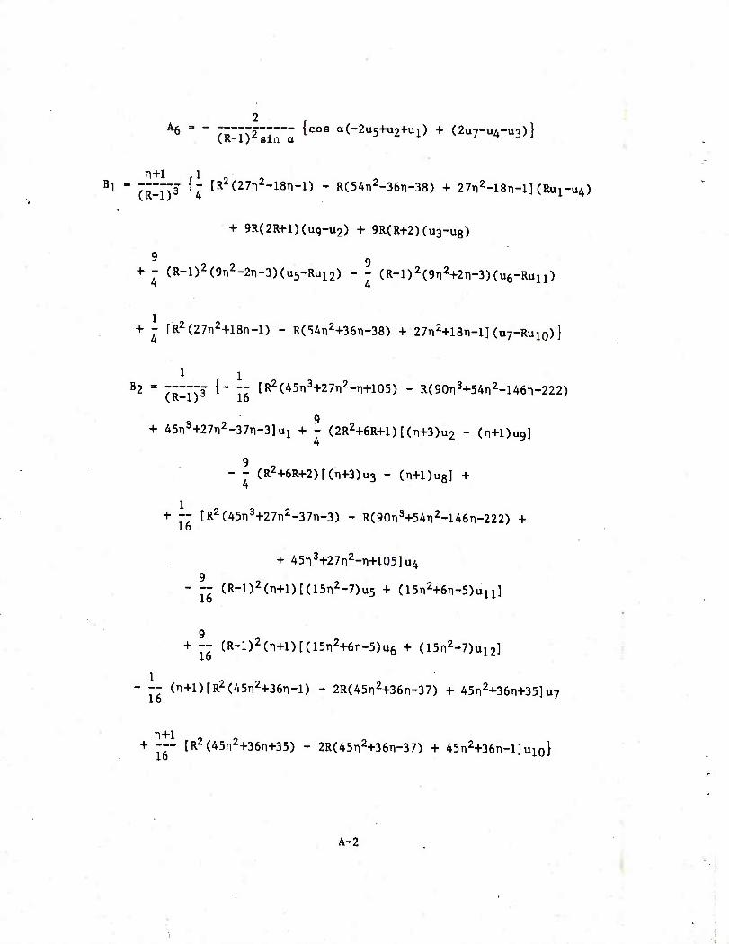
APPENDIX A
In this appendix we give the explicit expressions for the coefficients of
the various terras in the strain components given in the text.
R =■ /L
2(n+l)
(R:1)' Al = ""Vi {^(R-l)[Ru8-u6] + 4R[u7-U5]
+ (2nR+R-2n+l)[u2-Ru4] + (2nR-R-2n-l)[u3-Ru1]}
1 A „ _ {2(3n2+4n+l)(R-I)(u8-u6) + 4(n+l)(R+l)u7
2(R-1)2
- 4(n+3)(R+l)u5 + (R(3ri2+7n+4) - 3n(n+l))u4
+ (3Rn(Ti+l) - (3n2+7n+4))u3 + (R(3n2+5n+4) - (3Ti2+n-8))u2
- (R(3n2+T1-8) - (3T12+5n+4))u1}
2 A3 " ' (R-l)2 (2u5"u2-ul)
2((TI+1)CO8 a - (n-D) , AA {4Rn(R-l)u8 + 4R(u7-U5) - 4TI(R-1)U6
(R-l)zsin a
- (R(2n+1) - (2ri-l))(Ru4-U2) + (R(2TI-1) - (2ri+l))(u3-Ru1)}
A5 . .-- {2(R-l)[co8 a(3n2+4ri+l) - (3n2-4n+l)] (u8-u6) 3 2(R-l)2sin a
+ 4(R+l)(cos a(n+l) - (n-3))u7 - 4(R+l)(cos a(n+3) - (ri-l))u5
-(cos a[R(3Ti2+7n+4) - 3n(n+l)] - [R(3Ti2-n-8) - (3TI2
-5TI+4)] )u4
+ (cos ot[3Rn(n+l) - (3n2+7n+4)] - [R(3n2-5n+4) - (3n2-ri-8)] )u3
+ (cos a[R(3Ti2+5n+4) - (3n2+n-8)] + [-3Rti(n-X) + (3n2-7n+4)] )u2
- (cos a[R(3n2+ri-8) - (3TI2
+5TI+4)] + [-R(3n2-7n+4) + 3n(n-l)] )u1}
A-l
B
2 . A6 " " (RlnZg""^ 1C08 a(-2u5+U2+ul) + (2U7-U4-U3)}
1 - (i^T? ^4 [R2C27n2-l8n-l) - RCSAnMen-SS) + 27n2-18n-l 1(^x^4)
+ 9R(2R+l)(u9-U2) + 9R(R+2)(u3-u8)
9 9 + - (R-l)2(9n2-2T1-3)(u5-Ru12) - - (R-l)2(9n2+2n-3)(u6-Ru11)
+ - tR2(27n2+18Ti-l) - R(54n2+36n-38) + 27Ti2+18n-l] (u7-Ru10)}
82 " 7;"773 t" " [R2(^5Ti3+27n2-n+105) - R(90n3+54Ti2-146n-222)
9 + 45n3+27n2-37n-3]u1 + - (2R2+6R+l)[(n+3)u2 - (n+Dug]
9 - - (R2+6R+2)[(n+3)u3 - (n+Dug] +
+ -- [R2(45n3+27ri2-37n-3) - R(90Ti3+54Ti2-146t1-222) + 16
+ 45n3+27n2-n+l05]u4 9
- -- CR-l)2(n+l)[(15n2-7)u5 + (iSn^n-S)^!]
9 + — (R-l)2(n+l)[(l5n2+6n-5)u6 + (isn^u^]
- -7 (n+l)[R2(45n2+36n-l) - 2R(45n2+36n-37) + 45n2+36Ti+35]u7 16 '
+ --- [R^(45T12+36n+35) - 2R(45n2+36n-37) + 45n2+36n-l]u1o}
A-2
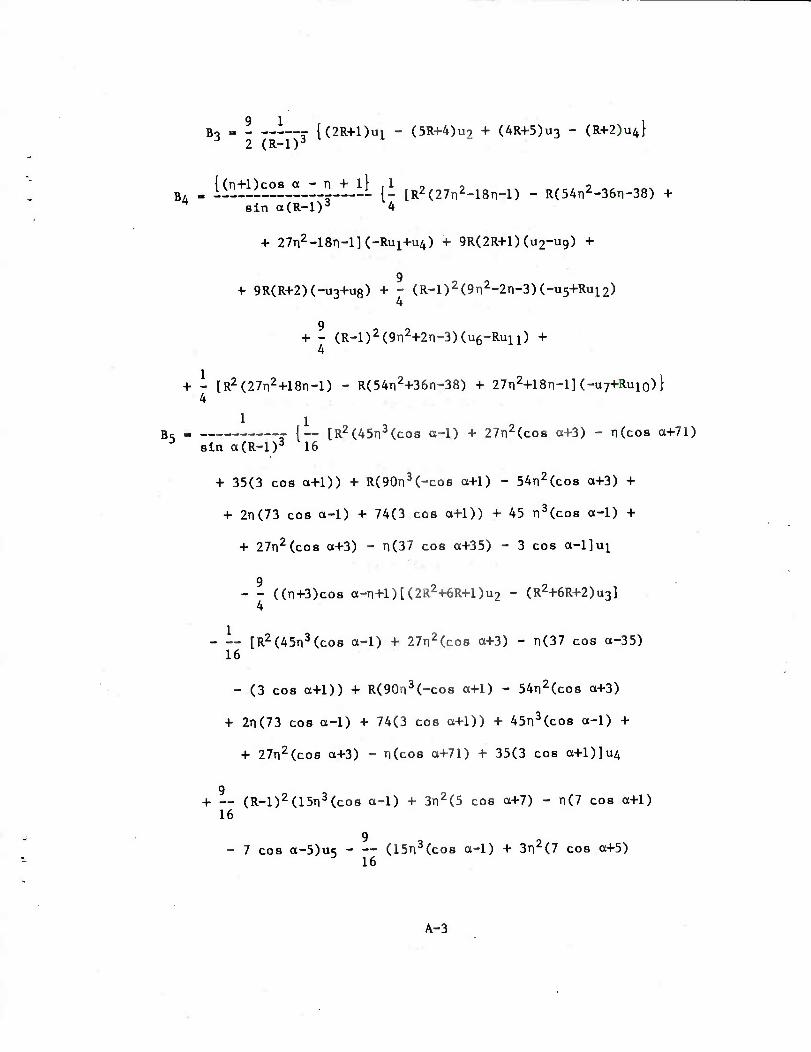
B- „ _ {(ZR+Dui - (5R+4)U2 + (4R+5)u3 - (R+2)u4} J 2 (R-l)3
B, . [^l^lJtJlJlJtA (i [R2(27n^l8n-l) - R(54n2-36n-38) + * sin a(R-l)3 4
+ 27n2-18n-l](-Ru1+u4) + 9R(2R+l)(u2-U9) +
9 + 9R(R+2)(-U3+u8) + - (R-l)2(9Ti2-2n-3)(-u5+Ru12)
4
9 + - (R-l)2(9n2+2ri-3)(u6-Ru11) +
4
+ - [R2(27n2+18n-l) - R(54n2+36n-38) + 27n2+18n-l](-U7+Ru1o)} 4
1 i B, « {— [R2(45n3(co8 a-1) + 27TI
2(COS a+3) - n(cos a+71)
3 sin a(R-l)3 16
+ 35(3 cos a+1)) + R(90n3(-cos a+1) - 54n2(cos a+3) +
+ 2n(73 cos a-1) + 74(3 cos a+1)) + 45 n3(co8 a-1) +
+ 27ri2(cos a+3) - n(37 cos a+35) - 3 cos a-l]ui
9 - - ((TI+3)COS a-n+l)[(2R2+6R+l)u2 - (R2+6R+2)u3]
4
[R2(45n3(cos a-1) + 27n2(cos a+3) - n(37 cos a-35) 16
- (3 cos a+1)) + R(90n3(-cos a+1) - 54n2(cos a+3)
+ 2n(73 cos a-1) + 74(3 cos a+1)) + 45TI3(COS a-1) +
+ 27n2(co8 a+3) - n(cos a+71) + 35(3 cos a+l)]u4
9 + — (R-l)2(15n3(cos a-1) + 3n2(5 cos a+7) - n(7 cos a+1)
16 9
- 7 cos a-5)u<5 (15n3(cos a-1) + 3n2(7 cos a+5) 3 16
A-3
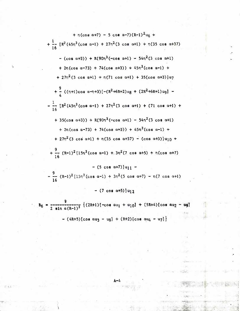
+ n(co8 a+7) - 5 cos a-7)(R-l)2u6 +
1 + — IR
2(45TI
3(CO8 a-1) + 27n2(3 cos a+1) + TI(35 cos a+37)
16
- (cos a+3)) + R(90n3(-cos a+1) - 54ri2(3 cos a+1)
+ 2n(co8 a-73) + 74(co8 a+3)) + 45n3(cos a-1) +
+ 27n2(3 cos a+1) + n(71 cos a+1) + 35(cos a+3)]u7
+ - ((n+l)cos a-ri+3)[-(R2+6R+2)u8 + (2R2+6R+l)u9] - 4
lR2(45n3(cos a-1) + 27TI2(3 COS a+1) + (71 cos a+1) +
16
+ 35(cos a+3)) + R(90TI3(-COS a+1) - 54n2(3 cos a+1)
+ 2TI(CO8 a-73) + 74(co8 a+3)) + 45n3(cos a-1) +
+ 27n2(3 cos a+1) + n(35 cos a+37) - (cos a+3)]uio +
+ — (R-l)2[15n3(cos a-1) +-3n2(7 cos a+5) + n(cos a+7) 16
- (5 cos a+7)]uii - 9 (R-l)2[15n3(cos a-1) + 3n2(5 cos a+7) - n(7 cos a+1)
16
- (7 cos a+5)]ui2
Bg =• {(2R+l)[-co8 aui + UIQ] + (5R+4)[cos 002 - ug] 2 sin a(R-l)a
- (4R+5)[cos au3 - us] + (R+2)[co8 au4 - uy]}
* ■., *>*;
r w A-4 mrn^
>■'%»'
TECHNICAL RKPORT INTERNAL DISTRIRUTION LIST
DIRECTOR, OPERATIONS DIRECTORATE
DIRECTOR, PRODUCT ASSURANCE DIRECTORATE
NOTE: PLEASE NOTIFY ASSOC. DIRECTOR, BENET WEAPONS LABORATORY, ATTN DRDAR-LCB-TL, OF ANY REQUIRED CHANGES.
NO. OF COPIES
COMMANDER l
CHIEF, DEVELOPMENT ENGINEERING BRANCH 1 ATTN: DRDAR-LCB-DA l
-DM ! -DP 1 -DR • 1 -DS 1 -DC 1
CHIEF, ENGINEERING SUPPORT BRANCH 1 ATTN: DRDAR-LCB-SE l
■ -SA 1
CHIEF, RESEARCH BRANCH 2
ATTN: DRDAR-LCB-RA l
-RC 1 -RM 1 -RP l
CHIEF, LWC MORTAR SYS. OFC. l
ATTN: DRDAR-LCB-M
CHIEF, IMP. SIMM MORTAR OFC. l
ATTN: DRDAR-LCB-I
TECHNICAL LIBRARY 5
ATTN: DRDAR-LCB-TL
TECHNICAL PUBLICATIONS § EDITING UNIT 2
ATTN: DRDAR-LCB-TL
1
DIRECTOR, PROCUREMENT DIRECTORATE I
1
TECHNICAL RKPOHT INTERNAL DISTRIBUTION LIST
NO. Oi> GOPIES
NO. OF CHPIFS
ASST SEC OF THE ARMY RESEARCH & DEVELOPMENT ATTN: DEP FOR SCI & TECH 1 THE -PENTAGON WASHINGTON, D.C. 20315
COWANDER US ARMY I/AT DEV & READ. COVDD ATTN: DRCDE I 5001 EISENHOWER AVE ALEXANDRIA, VA 22333
CaWIANDER US ARMY ARRADCCM ATTN: DRDAR-LC 1
-ICA (PIASTICS TECH 1 EVAL CEN)
-LCE 1 -LCM 1 -LCS 1 -LOW 1 -TSS(STINFO) 2
Da\fER, NJ 07801
CQvPJlANDER US ARMY ARRCCM ATTN: DRSAR-LEP-L 1 ROCK ISLAND ARSENAL ROCK ISIAND, IL 61299
DIRECTOR US Army Ballistic Research Laboratory ATTN: DRDAR-TSB-S (STINFO) 1 ABERDEEN PROVING GROUND, MD 21005.
CQM/ftNDER US ARMY ELECTRONICS CCMD ATTN: TECH LIB 1 FT MONMOUTH, NJ 077D3
CQvMANDER US ARMY MOBILITY EQUIP R&D CCMD ATTN: TECH LIB 1 FT BELVOIR, VA 22060
NOTE: PLEASE NOTIFY CCMMANDER, ARRADCCM, ATTN: BENET WEAPONS LABORATORY, DRDAR-LCB-TL, WATERVLIET ARSENAL, WATERVLIET, N.Y. 12189, OF ANY REQUIRED CHANGES.
COMMANDER US ARMY TANK-AUTMV RAD CCMD ATTN: TECH LIB - DRDTA-UL
MAT LAB - DRDTA-RK WA[{REN MICHIGAN ^8090
CCMMANDER US MILITARY ACADF?y/!Y ATTN: CHMN, MECH li^JGR DEPT WEST POINT, NY 10996
CCMMANDER REDSTONE ARSENAL ATTN: DRSMI-RB
-RRS -RSM
ALABAMA 35809
CCMMANDER ROCK ISLAND ARSENAL ATTN: SARRI-ENM (MAT SCI DIV) ROCK ISLAND, IL 61202
CCMMANDER HQ, US ARMY AVN SCH ATTN: OFC OF THE LIBRARIAN FT RUCKER, ALABAMA 36362
CCMMANDER US ARMY FGN SCIENCE & TECH CEN ATTN: DRXST-SD 220 TTH STREET, N.E. CHARLOTTESVILLE, VA 22901
CCMMANDER US ARMY MATERIALS & MECHANICS
RESEARCH CENTER ATTN: TECH LIB - DRXMR-PL WATERTOWN, MASS 02172
1 -i
2 1 1
TECHNICAL REPORT EXTERNAL DISTRIBUTION LIST (CONT.)
NO. OF COPIES
CCWMANDER US ARMJf RESEARCH OFFICE- P.O. BOX 12111 RESEARCH TRIANGLE PARK, NC 27739
CCWMANDER US ARMY HAHSY DIAJ^OND LAB ATTN: TECH LIB 2800 PCWDER MILL ROAD ADELPHIA, ME 20783
DIRECTOR US ARMY INDUSTRIAL BASE ENG ACT ATTN: DRXPE-MT ROCK ISUND, IL 61201
CHIEF, MATERIALS BRANCH US ARMY ftSS GROUP,, EUR BOX 65, FPO N.Y, 09510
CQ^^MANDER NAVAL SURFACE WEAPONS CEN ATTN: CHIEF, MAT SCIENCE DIV DAHLGREN, VA 22^8
DIRECTOR US NAVAL RESEARCH LAB ATTN: DIR, MBCH DIV
CCTE 26-27 (DOC LIB) WASHINGTON, D. C. 33375
NASA SCIENTIFIC & TECH INFO FAC. P. 0. BOX S757, ATTN: ACQ BR BALTIWORE/WASHINGTCN INTL AIRPORT MAHYIAND 21240
1 1
CCMMANDER DEFENSE TECHNICAL INFO CENTER ATTN: DTIA-TCA CAMERON STATION ALEXANDRIA, VA 22314
METAIo 4 CERAMICS INFO CEN BATTELLE COLUMBUS LAB 505 KING AVE COLUMBUS, CHIO 43331
MECHANICAL PROPERTIES DATA CTR BATTELLE COLUMBUS LAB 505 KING AVE COLUMBUS, OHIO 43201
MATERIEL SYSTEIE ANALYSIS ACTV ATTN: DRXSY-MP ABERDEEN PROVING GROUND MAHYUND 21005
NO. OF COPIES
12
NOTE: PLEASE NOTIFY CCLMANDER, ARRADCCW, ATTN: BENET WEAPONS LABORATORY, DRDAF.-LCB-TL, WATERVLIET ARSENAL, WATERVLIET, N.Y. 12189, OF ANY REQUIRED CHANGES.