Embed Size (px)
Citation preview


P1: FPP 2nd Revised Pages Qu: 00, 00, 00, 00
Encyclopedia of Physical Science and Technology EN002C-64 May 19, 2001 20:39
Table of Contents (Subject Area: Polymers)
Article AuthorsPages in the
Encyclopedia
Biopolymers E. Ann MacGregor Pages 207-245
Macromolecules,
Structure
Peter A. Mirau, Lynn W.
Jelinski and Frank A. Bovey Pages 857-901
Plastics Engineering R. J. Crawford Pages 457-474
Polymer Processing Donald G. Baird Pages 611-643
Polymers, Electronic
Properties J. Mort Pages 645-657
Polymers,
Ferroelectric
T. C. Mike Chung and A.
PetchsukPages 659-674
Polymers, Inorganic
and Organometallic Martel Zeldin Pages 675-695
Polymers,
Mechanical Behavior Garth L. Wilkes Pages 697-722
Polymers,
Photoresponsive (in
Elsa Reichmanis, Omkaram
Nalamasu and Francis Pages 723-744
Polymers, Recycling Richard S. Stein Pages 745-750
Polymers, Synthesis Timothy E. Long, James E.
McGrath and S. Richard Pages 751-774
Polymers, Thermally
Stable J. P. Critchley Pages 775-807
Rheology of
Polymeric Liquids Chang Dae Han Pages 237-252
Rubber, Natural Stephen T. Semegen Pages 381-394
Rubber, Synthetic Stephen T. Semegen Pages 395-405
P1: FPP 2nd Revised Pages Qu: 00, 00, 00, 00
Encyclopedia of Physical Science and Technology EN002C-64 May 19, 2001 20:39
BiopolymersE. Ann MacGregorUniversity of Manitoba
I. General Characteristics of PolymersII. Biopolymers
GLOSSARY
α-Amino acid Chemical compound containing a car-boxylic acid group (COOH) and an amino group (NH2)attached to one carbon atom.
Anomers Carbohydrates differing only in configurationof substituent groups at carbon 1 of an aldose sugar.
Configuration Arrangement of atoms in a moleculein space.One configuration cannot be changed toanother without breaking interatomic bonds in themolecule.
Conformation Arrangement of the atoms of a moleculein space, which can be changed by rotation of chemicalgroupings around single bonds in the molecule.
Covalent bond Bond between two atoms in which eachatom contributes one electron to the bonding.
Dalton Unit of atomic mass, equal to 1.66053 × 10⁻²⁷ kg.Gel Semisolid jelly of solid dispersed in liquid.Hydrogen bond Weak bond formed when a hydrogen
atom is shared between two electron-attracting atomssuch as oxygen or nitrogen.
Primary structure Sequence of monomer residues in apolymer chain.
Quaternary structure Arrangement of subunits of apolymer molecule in space (especially for pro-teins).Each subunit must itself be a polymer chain.
Secondary structure Regular folding of a polymer chain,stabilized by hydrogen bonding.
Tertiary structure Overall folding of a polymer chain,including relative orientations of secondary structures.
A POLYMER is a chemical substance whose moleculesare large and consist of many small repeating units cova-lently bonded together. In nature, a wide variety of poly-mers, the biopolymers, are synthesized by living organ-isms. Among such biopolymers are the proteins whichperform many different functions, such as acting as cat-alysts or regulators, the polysaccharides—important instructures and as energy reserves—and the nucleic acidswhich carry genetic information from one generation tothe next. In addition, rubber, a plant polymer, is an in-dustrially important elastomer, while little direct com-mercial use has yet been found for lignin, another abun-dant plant polymer. The microbial polyesters, polyhydrox-yalkanoates, are, in contrast, growing in importance asbiodegradable plastics made from renewable resources.
I. GENERAL CHARACTERISTICSOF POLYMERS
Polymer molecules, or macromolecules, are composed oflarge numbers of linked, small repeat units. The units fromwhich polymers are synthesized are called monomers.Polymers may be made from one kind of monomer, giving
207

P1: FPP 2nd Revised Pages
Encyclopedia of Physical Science and Technology EN002C-64 May 19, 2001 20:39
208 Biopolymers
homopolymers, or from several kinds of monomers, giv-ing copolymers. For many biopolymers the repeat units ofthe macromolecule are not identical in structure to themonomers, because a small molecule such as water iseliminated from the monomers during incorporation intothe polymer. This leaves monomer residues or repeat unitssmaller than the original monomers (e.g., consider threehypothetical monomers becoming linked at the start ofsynthesis of a polymer, as in I).
R OH �HO R OHHO R OHHO
R OHO R O R OH 2H2O
monomer residueor
repeat unit
I
�
�
The monomer is HOROH, while the repeat unit isR O . Molecules consisting of a small number (<20)
of repeat units are called oligomers, but there is no gener-ally accepted value for the number of repeat units whichdistinguishes a large oligomer from a small polymer. Inthis article the molecules of the polymers discussed gener-ally have a degree of polymerization (the number of repeatunits in the polymer molecule) of more than 30.
Where polymers are synthesized from monomers con-taining two chemically reactive, or functional, groups, theresultant polymer molecules are linear. If monomers havemore than two functional groups, however, branched oreven network polymers may be formed (Fig. 1).
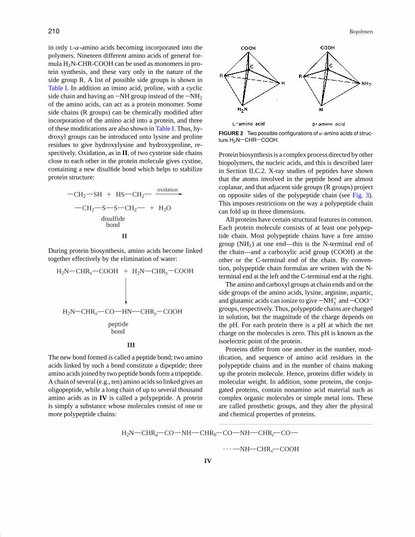
Carbon atoms are an important constituent of a biopoly-mer chain. Such atoms are usually bonded to four atomsor chemical groupings arranged tetrahedrally in space.When the four groups attached to one carbon atom aredifferent, two possible arrangements in space, or config-urations, are possible (Fig. 2). Biosynthesis of polymersis under strict stereochemical control, however, and usu-ally only one possible configuration is incorporated intoa biopolymer. Thus, proteins, which are polymers of α-amino acids, are synthesized from L-α-amino acids only,and not from D-α-amino acids (see Fig. 2).
In copolymers, where more than one monomer residue(say A and B) is present, these residues can be arrangedalong the polymer chain in different ways, giving for ex-ample an apparently random sequence A–B-A-A-B-A-B-B-B-A-A-, or an alternating sequence A-B-A-B-A-B-A-B-, or a sequence consisting of a block of one residuefollowed by a block of the other A–A-A-A-A-A-A-B-B-
B-B-B-. Examples of all these kinds of biopolymer ar-rangements are known.
A polymer sample may consist of a collection of iden-tical molecules (i.e., with the same sequence of monomerresidues, the same position and length of branches [wherepresent] and the same degree of polymerization). On theother hand, polymers are known where the moleculesare heterogeneous with respect to number and sequenceof monomer residues and distribution of branches. Pro-teins and nucleic acids, for example, fall in the first cate-gory, while polysaccharides and lignin come in the secondcategory.
One of the characteristics of polymers, apart frommolecular size, which distinguishes them from substancesmade of small molecules is the importance of nonco-valent bonding between two parts of the same polymermolecule or between two separate molecules. This non-covalent bonding can be of various kinds. Hydrogen bond-ing arises when hydrogen atoms are shared between twoatoms such as oxygen or nitrogen which carry partial neg-ative charges. Hydrogen bonds are particularly commonin biopolymers, but they can be disrupted easily by heat orchanges in acidity (or pH) of the environment of the poly-mer. Many groups attached to polymer main chains canionize, and electrostatic attractions, or ionic bonding, canoccur between positively and negatively charged group-ings. Conversely, groups carrying like charges repel eachother. Ionic bonding is important in many proteins and in-organic polymers but again can be lessened by changes inpH of the environment. In proteins, it is often found thathydrocarbon groups associate with each other. This hy-drophobic interaction excludes water from the vicinity ofthe hydrocarbon groupings. In fact, it is this exclusion ofwater which provides the driving force for the association.In addition to these kinds of bonding, all atoms in closecontact attract each other weakly. Such forces are calledvan der Waals forces and can be important in the interiorsof highly folded and compact polymer molecules.
II. BIOPOLYMERS
A large number of polymers, differing widely in structureand function, are synthesized in living organisms. It isconvenient, therefore, to discuss biopolymers in groups,rather than as a whole. The polymers described below havebeen assigned to groups on the basis of structure, but atbest this division is approximate.
Although individual polymers are important, in livingorganisms it is often the interactions between biopolymerswhich confer on a tissue its form and function. Much workis now being carried out to elucidate these interactions.

P1: FPP 2nd Revised Pages
Encyclopedia of Physical Science and Technology EN002C-64 May 19, 2001 20:39
Biopolymers 209
FIGURE 1 (a) Formation of a linear polymer from monomer A with two functional groups and (b) formation of nonlinearpolymers from monomer B with three functional groups: (i) branched polymer, (ii) branch-on-branch polymer, and (iii)network polymer.
A. Proteins
All proteins are polymers of α-amino acids, but they differin three-dimensional molecular structure and in the func-tions they perform in living organisms. Protein moleculescan, for example, have structural, transporting, or regula-tory roles; in addition, as antibodies they protect mammalsfrom disease and as enzymes act as the most efficient cat-alysts known. As our knowledge of protein structure has
increased, so also has our understanding of the relation-ship between structure and function.
1. Structure
As mentioned earlier, the monomers of proteins are α-amino acids. Such acids can exist in two configurations(see Fig. 2), but the strict stereochemical requirementsof the processes involved in protein biosynthesis result
P1: FPP 2nd Revised Pages
Encyclopedia of Physical Science and Technology EN002C-64 May 19, 2001 20:39
210 Biopolymers
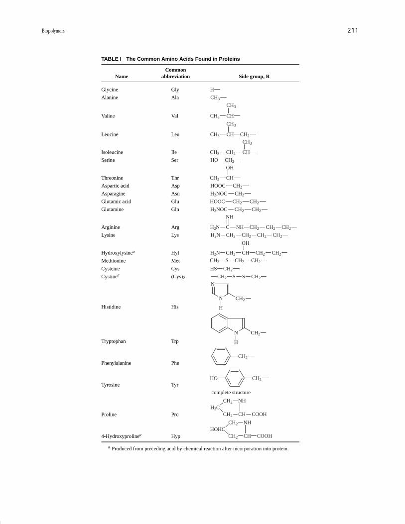
in only L-α-amino acids becoming incorporated into thepolymers. Nineteen different amino acids of general for-mula H2N-CHR-COOH can be used as monomers in pro-tein synthesis, and these vary only in the nature of theside group R. A list of possible side groups is shown inTable I. In addition an imino acid, proline, with a cyclicside chain and having an NH group instead of the NH2
of the amino acids, can act as a protein monomer. Someside chains (R groups) can be chemically modified afterincorporation of the amino acid into a protein, and threeof these modifications are also shown in Table I. Thus, hy-droxyl groups can be introduced onto lysine and prolineresidues to give hydroxylysine and hydroxyproline, re-spectively. Oxidation, as in II, of two cysteine side chainsclose to each other in the protein molecule gives cystine,containing a new disulfide bond which helps to stabilizeprotein structure:
CH2 SH CH2HS
H2O
disulfidebond
II
CH2 S S CH2
oxidation�
�
During protein biosynthesis, amino acids become linkedtogether effectively by the elimination of water:
H2N CHRx �
peptidebond
III
COOH H2N CHRy COOH
H2N CHRx CO HN CHRy COOH
The new bond formed is called a peptide bond; two aminoacids linked by such a bond constitute a dipeptide; threeamino acids joined by two peptide bonds form a tripeptide.A chain of several (e.g., ten) amino acids so linked gives anoligopeptide, while a long chain of up to several thousandamino acids as in IV is called a polypeptide. A proteinis simply a substance whose molecules consist of one ormore polypeptide chains:
IV
NH CHRx COOH
H2N CHRa CO NH CHRb CO NH CHRc CO
FIGURE 2 Two possible configurations of α-amino acids of struc-ture H2N CHR COOH.
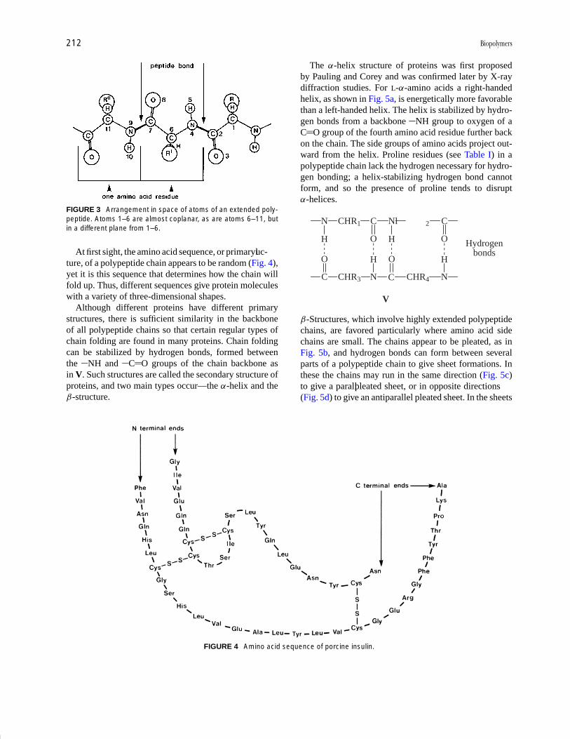
Protein biosynthesis is a complex process directed by otherbiopolymers, the nucleic acids, and this is described laterin Section II.C.2. X-ray studies of peptides have shownthat the atoms involved in the peptide bond are almostcoplanar, and that adjacent side groups (R groups) projecton opposite sides of the polypeptide chain (see Fig. 3).This imposes restrictions on the way a polypeptide chaincan fold up in three dimensions.
All proteins have certain structural features in common.Each protein molecule consists of at least one polypep-tide chain. Most polypeptide chains have a free aminogroup (NH2) at one end—this is the N-terminal end ofthe chain—and a carboxylic acid group (COOH) at theother or the C-terminal end of the chain. By conven-tion, polypeptide chain formulas are written with the N-terminal end at the left and the C-terminal end at the right.
The amino and carboxyl groups at chain ends and on theside groups of the amino acids, lysine, arginine, aspartic,and glutamic acids can ionize to give NH+
3 and COO−
groups, respectively. Thus, polypeptide chains are chargedin solution, but the magnitude of the charge depends onthe pH. For each protein there is a pH at which the netcharge on the molecules is zero. This pH is known as theisoelectric point of the protein.
Proteins differ from one another in the number, mod-ification, and sequence of amino acid residues in thepolypeptide chains and in the number of chains makingup the protein molecule. Hence, proteins differ widely inmolecular weight. In addition, some proteins, the conju-gated proteins, contain nonamino acid material such ascomplex organic molecules or simple metal ions. Theseare called prosthetic groups, and they alter the physicaland chemical properties of proteins.
P1: FPP 2nd Revised Pages
Encyclopedia of Physical Science and Technology EN002C-64 May 19, 2001 20:39
Biopolymers 211
TABLE I The Common Amino Acids Found in Proteins
CommonName abbreviation Side group, R
Glycine Gly H
Alanine Ala CH3
Valine Val CHCH3
CH3
Leucine Leu CHCH3
CH3
CH2
Isoleucine Ile CH2CH3 CH
CH3
Serine Ser CH2HO
Threonine Thr CHCH3
OH
Aspartic acid Asp CH2HOOC
Asparagine Asn CH2H2NOC
Glutamic acid Glu CH2CH2HOOC
Glutamine Gln CH2CH2H2NOC
Arginine Arg NHCH2N CH2
NH
CH2 CH2
Lysine Lys CH2H2N CH2 CH2 CH2
Hydroxylysinea Hyl CH2H2N CH CH2 CH2
OH
Methionine Met CH2S CH2CH3
Cysteine Cys CH2HS
Cystinea (Cys)2 CH2 S S CH2
Histidine His
N
N CH2
H
Tryptophan Trp
N CH2
H
Phenylalanine PheCH2
Tyrosine TyrCH2HO
complete structure
Proline Pro
CH2
H2CCH2
NH
CH COOH
4-Hydroxyprolinea Hyp
CH2
HOHCCH2
NH
CH COOH
a Produced from preceding acid by chemical reaction after incorporation into protein.
P1: FPP 2nd Revised Pages
Encyclopedia of Physical Science and Technology EN002C-64 May 19, 2001 20:39
212 Biopolymers
FIGURE 3 Arrangement in space of atoms of an extended poly-peptide. Atoms 1–6 are almost coplanar, as are atoms 6–11, butin a different plane from 1–6.
At first sight, the amino acid sequence, or primaryluc-ture, of a polypeptide chain appears to be random (Fig. 4),yet it is this sequence that determines how the chain willfold up. Thus, different sequences give protein moleculeswith a variety of three-dimensional shapes.
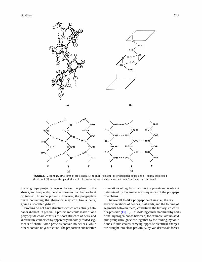
Although different proteins have different primarystructures, there is sufficient similarity in the backboneof all polypeptide chains so that certain regular types ofchain folding are found in many proteins. Chain foldingcan be stabilized by hydrogen bonds, formed betweenthe NH and C O groups of the chain backbone asin V. Such structures are called the secondary structure ofproteins, and two main types occur—the α-helix and theβ-structure.
FIGURE 4 Amino acid sequence of porcine insulin.
The α-helix structure of proteins was first proposedby Pauling and Corey and was confirmed later by X-raydiffraction studies. For L-α-amino acids a right-handedhelix, as shown in Fig. 5a, is energetically more favorablethan a left-handed helix. The helix is stabilized by hydro-gen bonds from a backbone NH group to oxygen of aC O group of the fourth amino acid residue further backon the chain. The side groups of amino acids project out-ward from the helix. Proline residues (see Table I) in apolypeptide chain lack the hydrogen necessary for hydro-gen bonding; a helix-stabilizing hydrogen bond cannotform, and so the presence of proline tends to disruptα-helices.
N CHR1 C Nl 2 C
H HO O
C CHR3 N C CHR4 N
O OH H
V
Hydrogenbonds
β-Structures, which involve highly extended polypeptidechains, are favored particularly where amino acid sidechains are small. The chains appear to be pleated, as inFig. 5b, and hydrogen bonds can form between severalparts of a polypeptide chain to give sheet formations. Inthese the chains may run in the same direction (Fig. 5c)to give a parallpleated sheet, or in opposite directions(Fig. 5d) to give an antiparallel pleated sheet. In the sheets
P1: FPP 2nd Revised Pages
Encyclopedia of Physical Science and Technology EN002C-64 May 19, 2001 20:39
Biopolymers 213
FIGURE 5 Secondary structures of proteins: (a) α-helix, (b) “pleated” extended polypeptide chain, (c) parallel pleatedsheet, and (d) antiparallel pleated sheet. The arrow indicates chain direction from N-terminal to C-terminal.
the R groups project above or below the plane of thesheets, and frequently the sheets are not flat, but are bentor twisted. In some proteins, however, the polypeptidechain containing the β-strands may coil like a helix,giving a so-called β-helix.
Proteins do not have structures which are entirely heli-cal or β-sheet. In general, a protein molecule made of onepolypeptide chain consists of short stretches of helix andβ-structure connected by apparently randomly folded seg-ments of chain. Some proteins contain no helices, whileothers contain no β-structure. The proportion and relative
orientations of regular structures in a protein molecule aredetermined by the amino acid sequences of the polypep-tide chains.
The overall folditf a polypeptide chain (i.e., the rel-ative orientations of helices, β-strands, and the folding ofsegments between them) constitutes the tertiary structureof a proteilln (Fig. 6). This folding can be stabilized by addi-tional hydrogen bonds between, for example, amino acidside groups brought close together by the folding, by ionicbonds if side chains carrying opposite electrical chargesare brought into close proximity, by van der Waals forces

P1: FPP 2nd Revised Pages
Encyclopedia of Physical Science and Technology EN002C-64 May 19, 2001 20:39
214 Biopolymers
FIGURE 6 Tertiary structure of a hypothetical protein. The cylin-ders represent helices, while the arrows represent pleated sheetstrands. The five strands of β-structure form a twisted parallelpleated sheet.
if side chains are packed closely together, by hydropho-bic interactions where hydrocarbon side chains come to-gether, and by the disulfide bonds of cystine (as in II).
Polypeptide chains of one protein usually adopt a pre-ferred tertiary structure that is essential for biological ac-tivity. The noncovalent bonding, which stabilizes tertiarystructure, can easily be weakened by heat or changes in pHand salt concentration. When this happens, the polypep-tide chains unwind and become randomly coiled. Biolog-ical activity is lost and the protein is said to be denatured.For some proteins, removal of the denaturing agent per-mits a return of the preferred tertiary structure and of bi-ological activity. The protein is then said to be renatured,and it is this ability to recover from unfolding which hasled us to believe that the information required to specifythe correct folding for biological activity is encoded in theamino acid sequences of polypeptide chains.
The tertiary structure of many proteins can be describedin terms of “domains” rather than polypeptide chains. Adomain is a polypeptide chain, or section thereof, oftenof molecular weight around 20,000 and which constitutesa geometrically separate entity (i.e., a region of regularand irregular folding separated from other such regionsby a longer stretch of irregular folding). Comparisons ofmany proteins have shown that the same structural do-main, characterized by its own folding pattern, may occurin different proteins or several times in one protein. As
the folding of more and more proteins is studied, we re-alize that most proteins can be described in terms of asmall number of regular packing arrangements of helicesand/or β-structures. Thus, proteins can be considered tobe constructed of modules, each module being a structuraldomain of mainly α-helices and/or β-structure. One pro-tein differs from another, then, in the number, type, andrelative arrangement of domains within the molecule, andin the detailed arrangement of amino acid side groups, Rgroups, on the molecular surface.
The tertiary structure of a protein molecule encom-passes the overall folding of polypeptide chains, where,if more than one chain is present, the chains are linkedby covalent bonds—most often disulfide bonds (as in II).However, some proteins exist where the molecules consistof several separate polypeptide chains; such chains wouldbe held together in the molecule by weaker bonds such ashydrogen and ionic bonds, hydrophobic interactions, andvan der Waals forces and each chain can act as a separatesubunit of the protein molecule. These proteins are said topossess quaternary structure (i.e., specific arrangementsof subunits within the macromolecule). Changes in sub-unit arrangement and even, to a small degree, in tertiarystructure of each subunit can take place while the proteincarries out its biological function. Proteins in which suchchanges take place are said to be allosteric.
In summary, any one protein has a unique primary struc-ture which in turn specifies the secondary and tertiarystructure (i.e., folding of the polypeptide chains). Rel-atively minor changes in tertiary structure are possibleas the protein functions in a living organism. Some pro-teins also possess quaternary structure which may undergochanges associated with biological activity.
2. Function
The functions of proteins are many and varied. Here rep-resentatives of some of the major functions are given, witha description where possible, of the relationship betweenstructure and activity.
Enzymes are an extremely important group ofproteins—the proteins that act as catalysts. These increasethe rates of reactions by factors of from 108 up to 1020,and so are the most efficient catalysts known. Unlike mostman-made catalysts, enzymes are extremely specific; eachenzyme catalyzes one reaction or a group of closely relatedreactions. The specificity extends not only to the chemicalnature of the reactants and products of a reaction but also tothe stereochemistry (i.e., arrangement of atoms in space)of the substances involved. Thus the enzymes of proteinbiosynthesis can distinguish between D- and L-α-aminoacids and ensure that only L-amino acids are incorporatedinto a growing polypeptide chain. In a living organism,
P1: FPP 2nd Revised Pages
Encyclopedia of Physical Science and Technology EN002C-64 May 19, 2001 20:39
Biopolymers 215
there are many hundreds of reactions occurring, each cat-alyzed by a specific enzyme.
The way in which enzymes bring about such large in-creases in reaction rate is not understood completely, buta number of factors probably contribute to the rate en-hancement. An enzyme forms a temporary complex withone or more of the reactants in a reaction. (The substanceswith which the enzyme interacts are called substrates forthe enzyme.) There is often strain on a substrate in such acomplex, allowing the substrate to react more readily thanif the enzyme were absent. Immobilization of a substrateon the surface of an enzyme can also allow a reaction tooccur more easily, particularly where a second reactantis involved. The enzyme brings the two substrates intoclose proximity. Some amino acid side groups are capableof donating and receiving protons (i.e., hydrogen ions),and if such groups on an enzyme are brought close to abond to be broken in a substrate, then bond breaking canoften occur more quickly. Some enzyme-catalyzed reac-tions proceed via formation of an intermediate covalentlybonded to the enzyme; formation of such an intermediateseems to speed up the overall reaction.
Enzymes may act singly or may function as a group in amultienzyme complex. Usually each enzyme of a multien-zyme complex is responsible for catalyzing one step of acomplicated multistep biochemical pathway. Here greateracceleration of reaction rate is possible if one enzyme“passes on” the product of its reaction to the next enzymein the pathway.
Although enzyme molecules are large, the catalytic ac-tivity is usually associated with a relatively small area ofthe molecular surface, where the substrate is bound andreaction takes place. This area is called the active site ofthe enzyme. When an enzyme possesses quaternary struc-ture (i.e., consists of several separate polypeptide chains)there may be more than one active site per molecule. Theactive site is usually situated in a depression or a clefton the enzyme surface and is lined with amino acid sidegroups that can bind the substrate—usually by weak bondssuch as hydrogen bonds—and help to bring about the reac-tion being catalyzed. The active site is often formed fromparts of the polypeptide chain, which are well separated inprimary structure, but brought together by the folding ofthe chain. One enzyme differs from another in the shape ofits active site and the nature of the side groups at the site.In many enzymes, the remainder of the macromoleculesimply functions to maintain the shape and functionalityof the active site.
The shapes of enzyme molecules, and proteins in gen-eral, have been investigated by X-ray diffraction of proteincrystals (i.e., the folding of polypeptide chains in solid pro-teins has been studied). From studies of smaller proteinsof molecular weight 25,000 or less in solution by nuclear
magnetic resonance spectroscopy, it has been concludedthat a protein has the same overall shape in solution as inthe solid state, but that some minor changes can occur. Forenzymes it is known that a few amino acid side chains canchange position by several angstroms (10−10 m) when thesubstrate becomes bound to the enzyme molecule. Thus,the active shape, or conformation, of an enzyme moleculeis not rigidly defined, but alterations can take place as theenzyme carries out catalysis.
Many enzymes require the presence of ions or othersmall molecules in order to show catalytic activity. Thesenonprotein components are called cofactors, and a smallorganic cofactor is usually known as a coenzyme. A coen-zyme may be covalently bound to an enzyme, in whichcase it would be classified as a prosthetic group of theenzyme, or it may be loosely associated with the enzyme.Here the coenzyme often acts as a substrate for the en-zyme. Coenzymes are frequently derived from vitamins.Lack of such a vitamin in the human diet can result inan inactive enzyme or group of enzymes and can lead todevelopment of a deficiency disease.
In living tissues, the activities of many enzymes are reg-ulated by substances known as activators and inhibitors.These bind to enzymes and enhance or reduce the catalyticefficiency of the enzymes involved. Inhibitors can act sim-ply by binding at the active site and preventing substratebinding. Certain lethal nerve gases, for example, modifythe active site of an enzyme essential for the transmissionof nerve impulses; the result is paralysis and death. Wherethe functioning of an enzyme is critical for the metabolismof a disease-causing bacterium or virus, administration ofan enzyme inhibitor may be beneficial to an infected hu-man being. Thus inhibitors of an HIV enzyme necessaryfor virus maturation are important anti-AIDS drugs.
Many natural regulators of enzyme activity, however,bind noncovalently at sites in the enzyme molecule otherthan the active site. For these enzymes, then, parts of thepolypeptide chain(s) not involved in the active site havemore than a structural role; they also have a regulatory role.It is believed that the activators and inhibitors bring abouta change in the shape of the enzyme molecule and thatthis shape change controls the efficiency of the active site.Such enzymes are called allosteric enzymes, and manyconsist of several noncovalently bonded peptide chains.An inhibitor or activator may bind to one chain, whilethe active site is located on another. In a case like this,the active site is affected by a change in quaternary struc-ture when the regulatory molecule is bound. Allostericenzymes are believed to be capable of existing in inactiveand active states; binding of inhibitor favors the inactivestate, while binding of activators favors the active state.The active and inactive states differ slightly in tertiaryand/or quaternary structure.
P1: FPP 2nd Revised Pages
Encyclopedia of Physical Science and Technology EN002C-64 May 19, 2001 20:39
216 Biopolymers
The details of the mechanism of action differ for eachenzyme, but in each case a substrate is held by noncovalentforces at the enzyme surface. Amino acid side chains,and sometimes a coenzyme or metal ion, participate intransferring electrons, protons, or small functional groupsto or from the substrate to facilitate the reaction beingcatalyzed.
Transport and storage of ions and small molecules is an-other function often performed by proteins. For example,metal ions such as iron or potassium are transported withthe help of proteins. The transport and storage systemsinvolved in the utilization of oxygen have been studiedintensively. In human blood, oxygen is carried round thebody bound to a protein called hemoglobin; the oxygen isstored temporarily before use in tissues such as musclesby a related but less complex protein, myoglobin.
Both proteins are conjugated proteins (i.e., contain anonprotein prosthetic group). This group is heme, a flatorganic ring system with an iron(II) ion at the center. Thisiron ion is normally surrounded by six atoms, each ofwhich donates a pair of electrons to the iron. These atomsare four central nitrogens of the heme ring system, a ringnitrogen of a histidine residue (see Table I) of the polypep-tide chain and the oxygen of the oxygen molecule beingtransported. The heme group is colored, but uptake andrelease of oxygen cause a color change. The oxy formof hemoglobin is the bright red characteristic of arterialblood, while the deoxy form is the more purplish colorseen in blood in veins.
Myoglobin molecules consist of one polypeptide chainof about 150 amino acid residues and one heme group,while hemoglobin has four polypeptide chains and fourheme groups. In myoglobin, the chain is folded up to givethe overall shape of a flattened sphere, and about 80% ofthe amino acid residues are arranged in 8 α-helices. Theheme group is bound to the polypeptide chain by noncova-lent bonds. The polypeptide chain is folded in such a wayas to provide a hydrophobic pocket for the heme group,and in fact the main purpose for the polypeptide chain ofmyoglobin seems to be to provide a hydrophobic environ-ment for the iron(II) of the heme. This prevents the iron(II)from becoming readily oxidized to iron(III). Whereas theiron(II) of myoglobin and hemoglobin can bind oxygeneasily, iron(III) attached to the same proteins cannot.
The common form of hemoglobin consists of two pairsof identical chains, α-chains containing 141 amino acidresidues and β-chains of 146 amino acids. Each of thefour chains of hemoglobin is folded to provide a hy-drophobic pocket for the heme. Even though the pri-mary structures of hemoglobin and myoglobin differ, theirchains are folded in a similar way. The four chains ofhemoglobin are not covalently linked to each other but
are held together by hydrophobic, ionic, and hydrogenbonding. Thus, hemoglobin molecules possess quaternarystructure, and changes in this quaternary structure are im-portant in the uptake and release of oxygen.
Myoglobin, the storage protein, is required to have ahigh affinity for oxygen at the oxygen pressure of muscles.Hemoglobin, on the other hand, must have more complexproperties. The affinity for oxygen must be high at theoxygen pressure of the lungs and much lower in musclesso that the oxygen can be passed on to the myoglobin.This change is brought about by relatively small changesin tertiary and quaternary structure of the hemoglobinmolecules. The pH in muscles is usually slightly less thanthat in lungs, and this favors the deoxy form of hemoglobinover the oxy form. At this lower pH the side chains of cer-tain amino acids are positively charged and are involved ininterchain ionic bonding with negatively charged groupsclose by in the quaternary structure. In addition, the ironion lies out of the plane of the heme ring system. On oneside of the iron ion in both α-chains is a space capableof accommodating the oxygen molecule; in the β-chainsthis space is blocked by the side chain of an amino acidresidue. In lungs, when an oxygen molecule binds to theheme of one α-chain, the iron ion moves back into theplane of the heme ring, pulling part of the polypeptidechain with it. This in turn alters the position of one ofthe helices of the chain, and the movement causes thebreaking of some ionic and hydrogen bonds between anα- and a β-chain. A second oxygen can bind to a secondα-chain and bring about similar changes. With the break-ing of noncovalent bonds between the hemoglobin sub-units, however, changes in quaternary structure can takeplace. The α- and β-chains rotate with respect to eachother and the two β-heme groups move about 6 A closerto each other. The amino acid side groups of the β-chainswhich blocked the oxygen-holding space now move awayand oxygen can also bind to the hemes of the β-chains.Further ionic bonds are broken and protons can be re-leased, a situation favored at the higher pH of the lungs.In muscles the opposite changes take place. Although thefirst oxygen molecule is given up with some difficulty,the release of the other three oxygen molecules becomeseasier as changes in quaternary structure take place, chainend ionic bonds are remade and the oxygen “pockets” ofthe β-chains become reblocked.
Small molecules other than oxygen can also bind atthe heme groups. Unfortunately the affinity for carbonmonoxide is much higher than for oxygen, and so in anatmosphere containing carbon monoxide this molecule isbound preferentially. If the carbon monoxide level is highenough, insufficient amounts of oxygen are transportedfrom the lungs and death can ensue.

P1: FPP 2nd Revised Pages
Encyclopedia of Physical Science and Technology EN002C-64 May 19, 2001 20:39
Biopolymers 217
Other proteins in mammalian systems, the antibodies,serve to protect against invasion by bacteria or viruses.Foreign material such as bacterial protein or polysaccha-ride, on entering the bloodstream, provokes the synthesisof specific antibodies. The antibodies then combine withthe “foreign” molecules, known as antigens, and renderthem harmless. Stimulation of antibody synthesis in mancan be brought about by immunization, whereby a harm-less form of disease-producing bacteria or virus is intro-duced into the body and specific antibodies are formed.These are active against virulent forms of the same bac-terium and may remain in the bloodstream for years, af-fording protection against the disease. Unfortunately, “for-eign” tissue in the body elicits the same response, and so,for organ transplants to be successful and not be rejected,the immune response must be minimized by the adminis-tration of powerful immunosuppressant drugs.
Antibodies constitute a group of proteins known as theimmunoglobulins. In an adult human there are five classesof immunoglobulin, and the most prevalent, the IgG an-tibodies of blood, have been studied in some detail. EachIgG molecule contains two identical heavy chains of ap-proximately 440 amino acids and two identical light chainsof around 220 amino acids, all linked by disulfide bonds.It is believed that the chains are constructed of domains ofapproximately 110 amino acids. Each domain has similarfolding of the polypeptide chains and consists essentiallyof two antiparallel pleated sheets. The light chains, there-fore, contain two such domains, while the heavy chainshave four each.
Antibodies are specific for the antigens with which theycombine. Therefore, many different IgG molecules exist,but the primary structures of the three C-terminal domainsof a heavy chain and the C-terminal domain of a light chainare very similar from one IgG molecule to another. Theseare referred to as the constant regions of the heavy and lightchains, respectively. The N-terminal domains of both theheavy and light chains, however, show great diversity inamino acid sequence and are known as the variable regionsof the chains.
Different classes of antibody vary in the nature of theconstant regions of the heavy chains, but within one class(e.g., the IgG) the variable regions of the light and heavychains confer specificity on an antibody. The binding site isbelieved to be situated in a cleft (for a small antigen) or onan irregular surface (complementary to part of the surfaceof a large antigen) formed by parts of two variable do-mains in close proximity, one domain belonging to a lightchain and one to a heavy chain. Since each IgG moleculehas two light and two heavy chains, then each has twoantigen-binding sites. Binding of antigen is believed to in-volve noncovalent bonding between the antigen and amino
acid side chains on the antibody surface at the bindingsite.
Some proteins can serve yet another purpose in livingorganisms, where they can act as regulators of biochemi-cal pathways. Hormones are substances that act on targetcells and markedly alter the metabolism of those cells.Some hormones are small proteins or polypeptides, and itis believed that they interact with specific receptors on theouter surface of the target cell membrane. The receptorsthemselves are proteins, and binding of the hormone tothe receptor protein causes changes to occur within thecell. In some cases it is known that a messenger moleculeincreases in concentration in the affected cell, and thatthis messenger modifies enzyme activities within the cell.Thus glucagon, a polypeptide of 29 amino acid residuessecreted by the pancreas, acts on liver cells in this way andstimulates breakdown of glycogen (see Section II.B.6),giving an increase in blood glucose levels.
In many cases the direct effect (at the molecular level)of the hormone on its target cell is brought about by acomplex “cascade” of reactions. This is true for insulin,the most widely studied polypeptide hormone. Insulin issecreted by the pancreas and consists of two short chainsof 21 and 30 amino acids, linked by disulfide bonds (seeFig. 4). The hormone acts mainly on cells of liver, muscle,and fatty tissues, decreases glucose concentration in theblood, and promotes glycogen and fat synthesis. Aminoacid side chains on the surface of the insulin molecule areimportant for interaction with the insulin receptor at its tar-get cells. It is known that binding of insulin to the receptorstimulates the activity of an enzyme within the cell whichis intrinsic to the receptor. This enzyme, in turn, activatesother proteins and enzymes by adding phosphate groupsto specific amino acid side chains. The newly activatedproteins then affect other proteins to increase or reducetheir activity and utlimately bring about the effects asso-ciated with insulin action. Thus, for example, the insulinreceptor enzyme activates a second enzyme that stimu-lates glycogen synthase, which is capable of converting amodified glucose to the storage polysaccharide glycogen(see Section II.B.6). Hence insulin helps to control bloodglucose levels.
Other protein regulators, such as the repressors, act notat cell surfaces but interact with the nucleic acids whichcontrol protein synthesis. These are described later (Sec-tions II.C.2, and II.E).
In addition to the functions discussed above, proteinscan have a structural role in living organisms. Unlike manyof the water-soluble proteins already described, whichare often spherical in shape, structural proteins can beinsoluble and fibrous. They are synthesized in a solubleform, processed to give the insoluble material, and then
P1: FPP 2nd Revised Pages
Encyclopedia of Physical Science and Technology EN002C-64 May 19, 2001 20:39
218 Biopolymers
may be cross-linked to other polymers to give the struc-tural unit in living organisms.
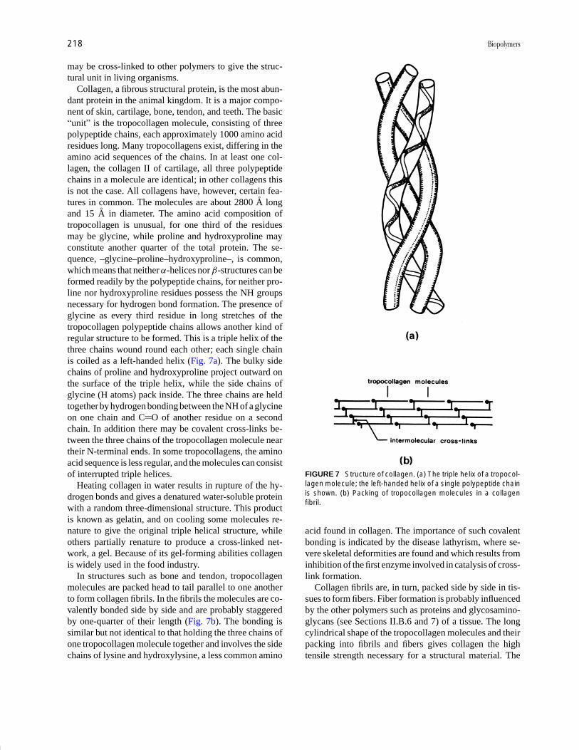
Collagen, a fibrous structural protein, is the most abun-dant protein in the animal kingdom. It is a major compo-nent of skin, cartilage, bone, tendon, and teeth. The basic“unit” is the tropocollagen molecule, consisting of threepolypeptide chains, each approximately 1000 amino acidresidues long. Many tropocollagens exist, differing in theamino acid sequences of the chains. In at least one col-lagen, the collagen II of cartilage, all three polypeptidechains in a molecule are identical; in other collagens thisis not the case. All collagens have, however, certain fea-tures in common. The molecules are about 2800 A longand 15 A in diameter. The amino acid composition oftropocollagen is unusual, for one third of the residuesmay be glycine, while proline and hydroxyproline mayconstitute another quarter of the total protein. The se-quence, –glycine–proline–hydroxyproline–, is common,which means that neither α-helices nor β-structures can beformed readily by the polypeptide chains, for neither pro-line nor hydroxyproline residues possess the NH groupsnecessary for hydrogen bond formation. The presence ofglycine as every third residue in long stretches of thetropocollagen polypeptide chains allows another kind ofregular structure to be formed. This is a triple helix of thethree chains wound round each other; each single chainis coiled as a left-handed helix (Fig. 7a). The bulky sidechains of proline and hydroxyproline project outward onthe surface of the triple helix, while the side chains ofglycine (H atoms) pack inside. The three chains are heldtogether by hydrogen bonding between the NH of a glycineon one chain and C O of another residue on a secondchain. In addition there may be covalent cross-links be-tween the three chains of the tropocollagen molecule neartheir N-terminal ends. In some tropocollagens, the aminoacid sequence is less regular, and the molecules can consistof interrupted triple helices.
Heating collagen in water results in rupture of the hy-drogen bonds and gives a denatured water-soluble proteinwith a random three-dimensional structure. This productis known as gelatin, and on cooling some molecules re-nature to give the original triple helical structure, whileothers partially renature to produce a cross-linked net-work, a gel. Because of its gel-forming abilities collagenis widely used in the food industry.
In structures such as bone and tendon, tropocollagenmolecules are packed head to tail parallel to one anotherto form collagen fibrils. In the fibrils the molecules are co-valently bonded side by side and are probably staggeredby one-quarter of their length (Fig. 7b). The bonding issimilar but not identical to that holding the three chains ofone tropocollagen molecule together and involves the sidechains of lysine and hydroxylysine, a less common amino
FIGURE 7 Structure of collagen. (a) The triple helix of a tropocol-lagen molecule; the left-handed helix of a single polypeptide chainis shown. (b) Packing of tropocollagen molecules in a collagenfibril.
acid found in collagen. The importance of such covalentbonding is indicated by the disease lathyrism, where se-vere skeletal deformities are found and which results frominhibition of the first enzyme involved in catalysis of cross-link formation.
Collagen fibrils are, in turn, packed side by side in tis-sues to form fibers. Fiber formation is probably influencedby the other polymers such as proteins and glycosamino-glycans (see Sections II.B.6 and 7) of a tissue. The longcylindrical shape of the tropocollagen molecules and theirpacking into fibrils and fibers gives collagen the hightensile strength necessary for a structural material. The
P1: FPP 2nd Revised Pages
Encyclopedia of Physical Science and Technology EN002C-64 May 19, 2001 20:39
Biopolymers 219
arrangement of fibers in a tissue depends on the nature ofthe tissue. In tendon, which requires great strength, fibersare arranged parallel to one another to give a structurewith the tensile strength of a light steel wire, while in skinwhere strength and flexibility are required, the fibers arerandomly oriented and woven together as in felt. Whererigidity is needed, as in bone, calcium salts are depositedto harden the tissue. The importance of the structural in-tegrity of collagen is demonstrated by the human defi-ciency disease scurvy, affecting gums, joints, and woundhealing. This results from a lack of vitamin C, ascorbicacid, now known to be required for the action of enzymesthat modify proline and lysine to give the hydroxy formsduring collagen synthesis.
Other structural proteins of some economic importanceare the fibroins, the main constituents of silk, which ap-pear to contain extensive antiparallel pleated sheets, andthe keratins which are the main structural proteins of furand wool, as well as of hair, skin, horn, hooves, nails,feathers, claws, and beaks. The keratin-containing struc-tures are extremely complex, but in wool and hair, forexample, there are α-helix-containing fibrils embedded inan amorphous matrix.
3. Utilization
The enzyme systems of microbes such as yeast have beenused for centuries in brewing and breadmaking. In the firstcase the yeast enzymes catalyze the conversion of glucoseto alcohol and in the second, carbon dioxide is producedand trapped in the dough to give a lighter texture to thebread. Microbial systems are also employed in the manu-facture of cheeses and in the production of antibiotics.
Nowadays purified enzymes are used on an industrialscale, often in solution. Thus, purified starch-degradingenzymes can be added in the early stages of brewing tospeed up production of glucose, and glucose syrups canbe made from starch by the action of enzymes. Enzymescan also be immobilized on an inert solid support overwhich substrate is passed. Such immobilized enzymes arefrequently employed to convert glucose to another sugar,fructose.
Many proteins are used in modern medicine. Antibodysynthesis can be deliberately stimulated in the human bodyto provide protection against future exposure to disease-producing viruses or bacteria. In some cases of severeinfection, antibodies can be administered directly to a pa-tient. Purified antibodies of very high specificity, calledmonoclonal antibodies, can now be prepared and are usedin diagnostic kits to confirm pregnancy or detect certaindiseases. In addition, radioactive or modified antibodiesto specific cell surface antigens can be synthesized. Theseantibodies can transport a radioactive isotope or a small
toxic molecule to target cells, which are then destroyedby the radioactivity or toxicity. In this way, for example,cancerous tumors can be reduced. Hormones can be givento alleviate diseases caused by a deficiency of that hor-mone. Thus, insulin is taken by those suffering from di-abetes mellitus; growth hormones can prevent dwarfism.Yet other proteins that are involved in blood clotting canbe used to prevent excessive bleeding in hemophiliacs.
Antibodies, because of their ability to bind specificmolecules, can be utilized in the preparation of purifiedantigens, where the antigen itself has useful properties.The antibody can be immobilized on an inert solid sup-port; antigen solution is allowed to flow over the support,and the antigens become bound selectively to the antibody-support complex. Disruption of antigen-antibody bindingallows pure antigen to be released and collected. This tech-nique can be used with many other proteins substitutingfor the antibodies, providing that these proteins show se-lective binding of useful substances.
Fibrous proteins such as found in wool and silk havebeen used for many centuries for clothing. The strength,flexibility, and water-holding abilities of the fibers haveprovided cloth which is both practical and comfortable.
Protein is also an essential foodstuff for man. We needamino acids from which to synthesize the proteins of ourown bodies; certain amino acids can be made by con-version of other molecules in the body, but some—theessential amino acids (Trp, Phe, Lys, Met, Leu, Ile, andVal)—must be obtained in our diet from external protein.
Gelatin, the denatured water-soluble form of collagen,is used widely in the food industry as a gelling agent.It is commonly used in fruit-flavored jellies and cannedmeats. The gel melts, however, at around 25◦C, so thesefoodstuffs should be kept at lower temperatures.
B. Polysaccharides
Polysaccharides are composed of small sugars, themonosaccharides, and a great variety of structure is found.Although they occur in almost all living organisms, theirfunctions seem to be more limited than those of pro-teins. Quantitatively, the most important polysaccharidesare energy reserves or perform a structural role, but otherpolysaccharides can act as lubricants or have a protectivefunction.
Several polysaccharides have industrial importance;these are usually polymers that can be obtained easily,in good yield, from any one source. Commercially use-ful polysaccharides are often prepared from higher plants,but marine algae and bacteria are also important sources.In some cases, however, polysaccharide mixtures may beobtained as a by-product of an industrial process, e.g.,hemicelluloses resulting from cellulose purification in

P1: FPP 2nd Revised Pages
Encyclopedia of Physical Science and Technology EN002C-64 May 19, 2001 20:39
220 Biopolymers
paper-making, but have not yet been fully developed as aresource.
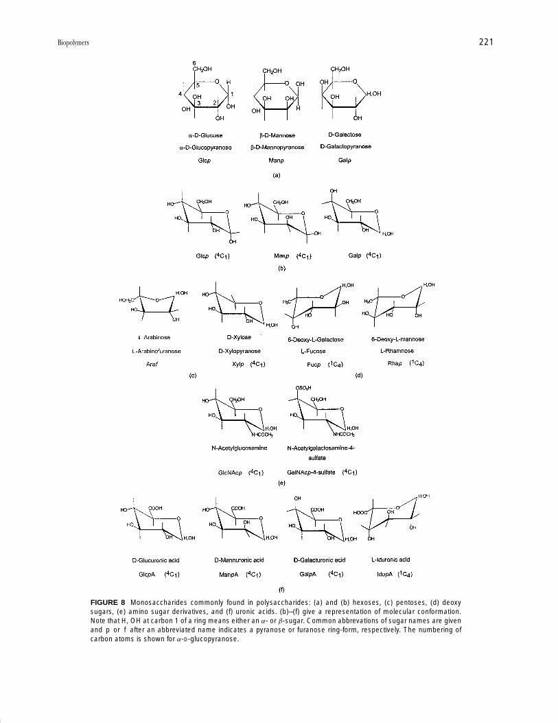
1. Structure
As stated above, the monomers of polysaccharides aremonosaccharides or sugars. Most of these have the gen-eral formula (CH2O)x, and were considered initially ashydrates of carbon, hence the name carbohydrates. Themost common monomers have five carbon atoms (the pen-toses) or six carbon atoms (the hexoses). Each monosac-charide has many hydroxyl (OH) groups on the molecule,and one monosaccharide differs from another in the ar-rangement in space of the hydroxyl groups. In solutiona monosaccharide can exist in a number of forms. Themonosaccharides can be thought of as carrying an alde-hyde or ketone group, and hence have reducing character.However, intra-molecular cyclization of a monosaccha-ride can occur to give a ring form, known as a hemiacetalor hemiketal, where the original aldehyde or ketone groupis masked by reaction with a hydroxyl group of the samemolecule. This cyclization gives a six-membered ringform (pyranose) or a five-membered ring form (furanose)(Fig. 8). Usually only one ring form of a monosaccharideis found in any one polysaccharide. Each monosaccha-ride can exist in two mirror-image forms, the D- and L-forms just as amino acids are found in D- and L-forms.Most monomer residues found in polysaccharides areD-sugars, but L-sugars do occur. This is unlike the case ofproteins where only L-amino acids are incorporated intopolymers.
The hydroxyl group on carbon 1 of a sugar such asglucose or mannose can be found either below or abovethe sugar ring, as shown in Fig. 8a for glucose or mannose.
VI
O
OH OH
OH
OH
CH2OHO
OH
OH
OH
CH2OH
H, OH�
O
OH
OH
OH
CH2OHO
OH
OH
CH2OH
H, OH
O
glycosidic bond
maltoseα-D-Glcp-(1-4)-D-Glcp
These two forms (anomeric forms) are distinguished as anα- or β-sugar. In the D-series of sugars, the α-form has theanomeric hydroxyl lying below the plane of the ring, whilein the L-sugars, this hydroxyl lies above the ring plane inthe α-form. The full name of a monosaccharide indicateswhether the sugar is α or β, D or L, which kind of sugaris being dealt with, and the size of the sugar ring, hencethe names α-D-glucopyranose and β-D-mannopyranose inFig. 8a.
Neither the furanose nor pyranose rings are flat, butare puckered. The most stable conformations of pyranosesugars are “chair” forms, and these are designated 4C1 or1C4, depending on whether the anomeric carbon (carbon 1)is at a top or bottom apex (Fig. 8). (Monosaccharides withsix-membered rings may be represented either by the “flat”projection of the pyranose ring shown in Fig. 8a, or bythe chair forms more closely related to three-dimensionalshape shown in Fig 8b.)
A wide variety of monosaccharides can be incorporatedinto polysaccharides and some of the most common areshown in Fig. 8. Not all monosaccharides have the gen-eral formula (CH2O)x. Some have one oxygen less; theseare the deoxy sugars (Fig. 8d). Others have a substitutedamino (NH2) group usually on carbon 2; these are theamino sugars (Fig. 8e). Others may carry sulfate groups;yet others have acid groups (COOH) instead of CH2OHat carbon 6; these are the uronic acids (Fig. 8f ).
The anomeric hydroxyl group of a sugar is the mostreactive and can act as a reducing group. Althoughpolysaccharide synthesis is complex, the net effect is thatmonosaccharides become linked together by reactions in-volving the anomeric hydroxyl of one monomer and thehydroxyl at another carbon of a second monomer, withelimination of water as in VI.
P1: FPP 2nd Revised Pages
Encyclopedia of Physical Science and Technology EN002C-64 May 19, 2001 20:39
Biopolymers 221
FIGURE 8 Monosaccharides commonly found in polysaccharides: (a) and (b) hexoses, (c) pentoses, (d) deoxysugars, (e) amino sugar derivatives, and (f) uronic acids. (b)–(f) give a representation of molecular conformation.Note that H, OH at carbon 1 of a ring means either an α- or β-sugar. Common abbrevations of sugar names are givenand p or f after an abbreviated name indicates a pyranose or furanose ring-form, respectively. The numbering ofcarbon atoms is shown for α-D-glucopyranose.
P1: FPP 2nd Revised Pages
Encyclopedia of Physical Science and Technology EN002C-64 May 19, 2001 20:39
222 Biopolymers
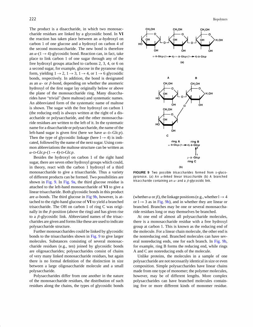
The product is a disaccharide, in which two monosac-charide residues are linked by a glycosidic bond. In VIthe reaction has taken place between an α-hydroxyl oncarbon 1 of one glucose and a hydroxyl on carbon 4 ofthe second monosaccharide. The new bond is thereforean α-(1 → 4)-glycosidic bond. Reaction can, in fact, takeplace to link carbon 1 of one sugar through any of thefree hydroxyl groups attached to carbons 2, 3, 4, or 6 ona second sugar, for example, glucose in the pyranose ringform, yielding 1 → 2, 1 → 3, 1 → 4, or 1 → 6 glycosidicbonds, respectively. In addition, the bond is designatedas an α- or β-bond, depending on whether the anomerichydroxyl of the first sugar lay originally below or abovethe plane of the monosaccharide ring. Many disaccha-rides have “trivial” (here maltose) and systematic names.An abbreviated form of the systematic name of maltoseis shown. The sugar with the free hydroxyl on carbon 1(the reducing end) is always written at the right of a dis-accharide or polysaccharide, and the other monosaccha-ride residues are written to the left of it. In the systematicname for a disaccharide or polysaccharide, the name of theleft-hand sugar is given first (here we have α–D–Glcp).Then the type of glycosidic linkage (here l → 4) is indi-cated, followed by the name of the next sugar. Using com-mon abbreviations the maltose structure can be written asα-D-Glcp-(1 → 4)-D-Glcp.
Besides the hydroxyl on carbon 1 of the right handsugar, there are seven other hydroxyl groups which could,in theory, react with the carbon 1 hydroxyl of a thirdmonosaccharide to give a trisaccharide. Thus a varietyof different products can be formed. Two possibilities areshown in Fig. 9. In Fig. 9a, the third glucose residue isattached to the left-hand monosaccharide of VI to give alinear trisaccharide. Both glycosidic bonds in this productare α-bonds. The third glucose in Fig 9b, however, is at-tached to the right-hand glucose of VI to yield a branchedtrisaccharide. The OH on carbon 1 of ring C was origi-nally in the β-position (above the ring) and has given riseto a β-glycosidic link. Abbreviated names of the trisac-charides are given and forms like these are used to indicatepolysaccharide structure.
Further monosaccharides could be linked by glycosidicbonds to the trisaccharides shown in Fig. 9 to give largermolecules. Substances consisting of several monosac-charide residues (e.g., ten) joined by glycosidic bondsare oligosaccharides; polysaccharides consist of chainsof very many linked monosaccharide residues, but againthere is no formal definition of the distinction in sizebetween a large oligosaccharide molecule and a smallpolysaccharide.
Polysaccharides differ from one another in the natureof the monosaccharide residues, the distribution of suchresidues along the chains, the types of glycosidic bonds
FIGURE 9 Two possible trisaccharides formed from D-gluco-pyranose. (a) An α-linked linear trisaccharide (b) A branchedtrisaccharide containing an α- and a β-glycosidic link.
(whether α or β), the linkage positions (e.g., whether l → 4or l → 3 as in Fig. 9b), and in whether they are linear orbranched. Branches may be one or several monosaccha-ride residues long or may themselves be branched.
At one end of almost all polysaccharide molecules,there is a monosaccharide residue with a free hydroxylgroup at carbon 1. This is known as the reducing end ofthe molecule. For a linear chain molecule, the other end isthe nonreducing end. Branched molecules can have sev-eral nonreducing ends, one for each branch. In Fig. 9b,for example, ring B forms the reducing end, while ringsA and C are nonreducing ends of the molecule.
Unlike proteins, the molecules in a sample of onepolysaccharide are not necessarily identical in size or evencomposition. Simple polysaccharides have linear chainsmade from one type of monomer; the polymer molecules,however, may be of different lengths. More complexpolysaccharides can have branched molecules contain-ing five or more different kinds of monomer residue.

P1: FPP 2nd Revised Pages
Encyclopedia of Physical Science and Technology EN002C-64 May 19, 2001 20:39
Biopolymers 223
Within a sample of a complex polysaccharide there can bemolecules differing in length and distribution of branches,and in distribution and number of each kind of monomerresidue. Because of this heterogeneity it has been more dif-ficult to study the three-dimensional structure of polysac-charides, for conventional investigations require crystalsmade of large numbers of identical molecules.
The kinds of glycosidic bonds and linkage positionsas well as the nature of the monosaccharide residues canhave a profound effect on the shape of the polysaccharidemolecules of which they are part. Polysaccharide chainsfold, for the most part, by rotation about the C O and O Cbonds of the interunit linkage. Free rotation is restricted,however, by the need for any large groups attached tothe monosaccharide rings to keep as far apart as possi-ble. In polysaccharides where monosaccharide residuesgive a regular repeating structure, only a small number ofchain conformations are likely, and some polysaccharidechains are most stable with a secondary structure of ex-tended ribbons, while others can coil up to give helices. Achain of β-(1 → 4)-linked D-glucopyranose residues, forexample, readily takes up an extended ribbon-like shapewhile a chain of α-(1 → 4)-linked D-glucopyranoses canform a helix. The extended chains and helices can bestabilized by intrachain hydrogen bonding involving OHgroups of the sugar residues. Bundles of extended chainscan be held together by interchain hydrogen bonding,and helices can consist of one or more chains and alsopack together in a regular way (Fig. 10). These organized
FIGURE 10 Stabilization of individual chain conformational pref-erences through interchain associations. (a) Extended ribbons inparallel or antiparallel alignment; (b) multiple helices as in amylosedouble helices or triple helices elsewhere; and (c) “egg box” modelwith anionic carboxyl groups cross-linked by divalent cations (•)with further coordination from hydroxyl groups (see Fig. 14). [FromAspinall, G. O. “Polysaccharides” in the Encyclopedia of PhysicalScience and Technology, Vol. 11, p. 176. Copyright 1987 by Aca-demic Press, Inc., New York.]
structures can exclude water from the neighborhood ofthe sugar hydroxyl groups and render the polysaccharidesinsoluble.
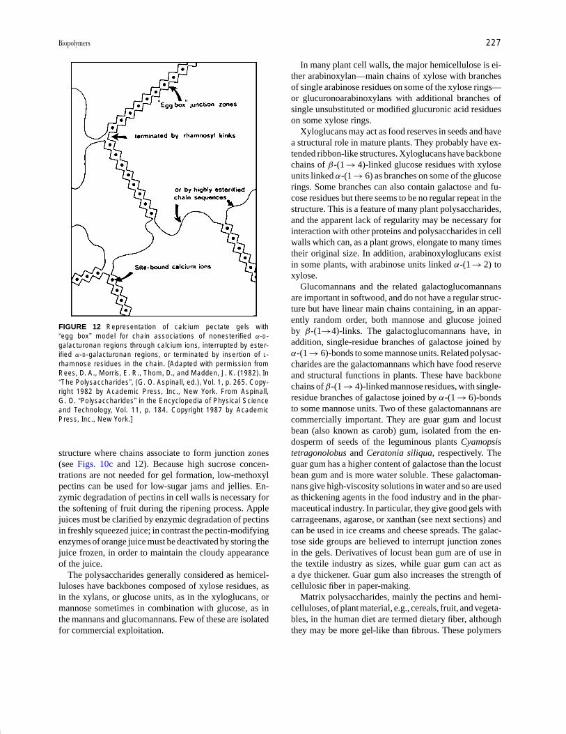
When structures are not so regular, however, polysac-charides may be able to form gels, characterized by anopen network that is stabilized by so-called junction zones,and where the open spaces are filled by solvent molecules.Such structures can be fairly rigid while containing as littleas 1% polysaccharide. The junction zones are formed byclose association of polysaccharide chain segments hav-ing a regular repeating structure, but are interrupted bysegments of irregular structure. If a single polysaccha-ride molecule possesses more than one stretch of chainwith structural regularity, each regular section can partici-pate in a junction zone involving different molecules, thusgenerating a network where the junction zones are sep-arated by segments of nonassociating chains of irregularstructure.
Chain associations may be of the types indicated inFigure 10, i.e., extended chains held together by hydro-gen bonding (Fig. 10a), chains wound round each otherin multiple helices (Fig. 10b), or chains containing ion-ized acid groups may associate by electrostatic attrac-tion of divalent cations such as Ca2+ to the negativelycharged polysaccharide (Fig. 10c). The latter is called the“egg box” model for formation of pectate and alginategels.
Junction zones may be interrupted by insertion of a dif-ferent monosaccharide unit in the main chain, causing akink in the structure, or alteration to an existing sugarresidue so that the ring conformation changes, or changesto substituents on an existing monosaccharide, also caus-ing a ring conformational change.
2. Classification
Whereas it is relatively easy to describe different proteinsin terms of their functions, this becomes more compli-cated for polysaccharides. Some polysaccharides seem tofulfill both structural and reserve roles, for example. It ismore convenient, therefore, to consider polysaccharides ingroups based on structure; based, in fact, on the nature ofthe monosaccharide residues making up the main polymerchain.
Polysaccharides can then be classified according tostructure and systematic names are given, dependingon monosaccharide composition. In some cases, how-ever, a trivial name is used, particularly for very com-plex polysaccharides, where the name preceded knowl-edge of structure. Homoglycans are composed of onekind of monosaccharide only; thus glucans consist ofchains of glucose residues, while xylans contain xyloseonly. They may be linear, with one or more linkage type.

P1: FPP 2nd Revised Pages
Encyclopedia of Physical Science and Technology EN002C-64 May 19, 2001 20:39
224 Biopolymers
TABLE II Examples of Linear and Branched Homo- and Heteroglycans
Type Common name Monosaccharide sequence
Homoglycans
Linear, one linkage type Amylose 4)-α-D-Glc p-(1 4)-α-D -Glc p-(1
Cellulose 4)-β-D-Glc p-(1 4)-β-D-Glc p-(1
Linear, more than one linkage type Cereal β-glucan 3)-β-D-Glc p-(1 4)-β-D-Glc p-(1
Branched Amylopectin 4)-α-D -Glc p-(1-Glc p-(1 4)-α-D
4)-α-
6
D-Glc p-1
HeteroglycansLinear, one linkage type Glucomannans 4)-β-D-Man p-(1 4)-β-D -Glc p-(1-Man p-(1 4)β-D
Linear, more than one linkage type Hyaluronic acid 4)-β-D -Glc pNAC-(1-Glc pA-(1 3)-β-D
Branched Galactomannan 4)-β-D-Man p-(1 4)-β-D-Man p-(1
α-D
6
-Gal p-1
Typical examples (Table II) of the first group would beamylose or cellulose, containing only (1 → 4)-glycosidicbonds, and of the second group, cereal β-glucans withboth β-(1 → 3) and β-(1 → 4)-bonds. The most com-plex homoglycans are branched, as is the case for amy-lopectin, also a glucan. Heteroglycans contain at leasttwo kinds of sugar unit, and the systematic name re-flects the monomer composition. Again, the polysaccha-ride molecules may be linear, with one or more linkagetype, or branched. Examples of linear heteroglycans (Ta-ble II) are glucomannans where glucose and mannoseresidues are linked by β-(1 → 4)-bonds and hyaluronicacid (here a trivial name is commonly used) containingglucuronic acid and N -acetyl glucosamine joined by β-(1 → 3)- andβ-(1 → 4)-linkages. Branched heteroglycanscan be much more complex, with one or more type ofmonosaccharide in the main chain and yet other sugarsin the branches, as is the case for plant pectins. With thisdegree of complexity, systematic nomenclature becomesdifficult.
The functions and uses of the most widely studied andcommercially important polysaccharides are described be-low, grouped according to source.
3. Plant Polysaccharides
Cellulose and starch are undoubtedly the plant polysac-charides of greatest importance, both in abundance andeconomic impact. Both are homopolymers of D-glucose,i.e., glucans.
Cellulose is the most abundant biopolymer and is themain structural material of the cell walls of higher plants.It has been estimated that there are approximately 1012 t
of cellulose present on the earth at any one time. Someplant fibers, such as ramie, hemp, jute, and notably cottonseed hairs, contain from 60% to over 90% cellulose andcan be used with minimum processing as textile fiber. Inwood, however, cellulose exists in close association withhemicelluloses and lignin (Section II.D) and harsh chem-ical treatments must be used to obtain cellulose, mainlyfor paper making.
Cellulose molecules are unbranched chains of β-(1 → 4)-linked glucopyranose units up to 5000 residueslong and are essentially rigid and extended. Individualβ-D-glucopyranose units adopt the 4C1 chair conforma-tion. Within one molecule, the ribbon-like shape is sta-bilized by hydrogen bonding between the ring oxygen ofone glucose unit and the OH on carbon three of the ad-jacent monomer residue, and also between the oxygenon carbon six of the first glucose and the OH on car-bon two of the adjacent residue. Cellulose molecules canalign themselves side by side, with adjacent chains run-ning in the same direction; these sheets are stabilized byhydrogen bonds between the OH on carbon six of glu-cose on one molecule and the oxygen on carbon threeof the closest glucose residue on an adjacent molecule.This structure is found in native, untreated cellulose andis called cellulose I. The forces between sheets are van derWaals forces, but the sheets associate to form microfibrils.These in turn aggregate to give fibers, which, in asso-ciation with other polysaccharides and proteins, are themain structural components of plant cell walls. CelluloseII is a form of cellulose obtained by chemical treatmentwith, for example, alkali. Here chains run antiparallel toone another and intermolecular hydrogen bonding differsfrom that in cellulose I. Where structure is well-ordered,

P1: FPP 2nd Revised Pages
Encyclopedia of Physical Science and Technology EN002C-64 May 19, 2001 20:39
Biopolymers 225
as in cellulose I and II, crystallites can form, but sam-ples of cellulose also contain amorphous regions wherechain packing is less regular. Chemical modification ofcellulose takes place more easily in these amorphousregions.
The cellulose derivatives of greatest commercial impor-tance are regenerated cellulose, and cellulose ethers andesters. Regenerated cellulose can be prepared by acidi-fying cellulose solutions in cuprammonium hydroxide oralkaline solutions of cellulose xanthate, and by removal ofester groupings from cellulose esters in organic solvents.The regenerated cellulose can be spun as fibers for textiles,e.g., rayon, or cast as films such as cellophane which isused for packaging.
Paper consists of a network of tangled cellulose fibersand is made mainly from wood chips treated with alkali orsulfur dioxide in bisulfite solution to remove most of thenoncellulosic constituents. Cellulose and cellulose deriva-tives are used to make textiles and plastics, and as thicken-ers and stabilizers. A variety of useful cellulose ethers areknown, varying in degree of substitution and nature of sub-stituents, and one of the most important is carboxymethylcellulose. Since it is considered safe for human consump-tion and is not degraded in or absorbed by the human diges-tive tract, it is used in foodstuffs and pharmaceuticals. Inlaboratories it has become important in modern techniquesfor purifying proteins. Cellulose acetates and nitrates areprobably the most useful esters. The acetates can be spuninto fibers and used in textiles, but in bulk form the acetatesare good thermoplastics. Cellulose trinitrate was first usedas an explosive; nitrates are now used as membranes andprotective coatings and can be cast as films (celluloid).Much interest is being shown in the possible utilization ofglucose, resulting from cellulose hydrolysis, as a feed-stock for chemical manufacture, to reduce reliance onpetroleum as the major source of raw material for chemicalindustry.
Starch is probably the second most abundant carbohy-drate polymer, and is an energy-reserve material of higherplants and some algae. It is granular in form and insol-uble in cold water, and is a major constituent of cerealgrains, potatoes, peas, and beans. Starch is generally con-sidered to consist of two glucan components, amylose andamylopectin, with 15–30% of “normal” starches beingmade up of amylose. Genetic variants of plants such asmaize can produce starches with no amylose or greaterthan 30% of this polysaccharide. Amylose molecules aremainly linear chains of α-(1 → 4)-linked D-glucopyranoseresidues while amylopectin has a highly branched struc-ture made up of chains of α-(1 → 4)-linked glucose unitsjoined by α-(1 → 6) bonds. About 4% of the residues ofamylopectin occur as branch points, while a small number
of branch points (<0.5%) can be found in some amylosemolecules. Amylose can adopt a helical conformation,the ring conformations being stabilized by intramolecu-lar hydrogen bonding between the OH on carbon 2 of aglucose residue and oxygen on carbon 3 of the adjacentglucose unit. Amylopectin probably has a structure wherechains are arranged in clusters (Fig. 11), with the longerα-(1 → 4)-linked glucose chains taking up double helicalconformations. The (1 → 6) bonds are more flexible than(1 → 4) links, and this allows the amylopectin moleculesto open up and give access to starch-degrading enzymes.The action of such enzymes is necessary when energy (inthe form of glucose) is required by the plant. Amylosemolecules in solution have a tendency to aggregate sideby side and become insoluble. This phenomenon is knownas retrogradation and is important in the staling of bakedproducts. At high temperatures (>80◦C) starch gives vis-cous solutions in water and, on cooling, forms a gel.
Starch is a natural energy source in the human diet.Because of this and its ability to form gels and highly vis-cous solutions, it is widely used in the food industry, as a
FIGURE 11 Cluster model for amylopectin wherein unbranchedA-chains are attached through branch points to B-chains. Longerchain segments in clusters permit the formation of helical do-mains analogous to those in amylose. Ø= single reducing unit permolecule. [Modified with permission from Robin, J. P., Mercier, C.,Duprat, F., Charbonniere, R., and Guilbot, A. (1975). Die Starke27, 36–45. Copyright 1975 by Verlag Chemie, Weinhem. FromAspinall, G. O. “Polysaccharides” in the Encyclopedia of Physi-cal Science and Technology, Vol. 11, p. 178. Copyright 1987 byAcademic Press, Inc., New York.]
P1: FPP 2nd Revised Pages
Encyclopedia of Physical Science and Technology EN002C-64 May 19, 2001 20:39
226 Biopolymers
thickener or gelling agent in soups and desserts. Starch isbroken down, mostly in the small intestine, to oligosaccha-rides and ultimately glucose. The most important enzymesinvolved in this hydrolysis are α-amylases (also foundin plants and microorganisms) that bring about mainlyrandom scission of α-(1 → 4)-glucosidic bonds to yieldoligosaccharides. Other enzymes then catalyze further hy-drolysis to glucose. Some starch, particularly after heatingand cooling of foodstuffs, is more resistant to attack andreaches the large intestine where it is fermented by the res-ident bacteria. This “resistant starch” is now believed toplay a part in prevention of some bowel diseases and maycontribute to lowering of blood cholesterol levels. Starchand starch derivatives are used in the textile and laun-dry industries—in the first as a warp size to strengthenthe yarn or as a finish to give a polish to thread, in thesecond to stiffen clothing and some household linens.Starch products are important in the paper industry forstrengthening the paper and improving the surface quality.Starch dextrins, prepared by heating dry starch, are widelyused as adhesives on labels, envelopes, postage stamps,etc., while minor outlets for starch are the oil industry(in drilling muds), ore refining (as a flocculating agent),smelting (as a binder in refineries), and biodegradableplastics.
The production of alcohol for human consumption isbased on the enzymic degradation of starch to glucose,followed by conversion of the glucose into ethyl alcohol.Alcohol for use as a fuel can also be made in this way.
Glucose and partially hydrolyzed starches (glucosesyrups) are made by enzymic and/or acid hydrolysis andfind wide use in the food and confectionery industries.Glucose is also used in pharmacy and medicine as an in-stant energy source. High fructose syrups, on a weightbasis sweeter than glucose syrups, are produced com-mercially from glucose solutions by passage over an im-mobilized enzyme, glucose isomerase. The possibilityof using glucose, from starch hydrolysis, as a feedstockfor biodegradable polyester production is currently un-der investigation (Section D). Further, the incorporationof starch polysaccharides into nonbiodegradable plastics,to improve their rate of break-down in the environment, isalso being studied.
In addition to cellulose, other polymers of β-linkedglucose units exist; these are the β-glucans. Some, frommicroorganisms and seaweeds, contain mostly (1 → 3)interunit links and seem to be food-reserve polysaccha-rides. Others are linear molecules containing (1 → 3) and(1 → 4) bonds in the ratio 1 : 3 and have a structural rolein, for example, endosperm cell walls of barley kernels.Soluble β-glucans of this type can give solutions of highviscosity in water, presumably because of the formation,
by molecular association, of a loose polymer network,although in some cases aggregation of helices may be in-volved. Some barley β-glucans can thus cause filtrationproblems in the brewing industry. There is evidence thatincreased cereal β-glucan in the human diet can play arole in lowering blood cholesterol levels that are consid-ered undesirably high.
Many structural tissues in living organisms appear to beconstructed from fibers embedded in an amorphous ma-trix. In plant cell walls, the fibers are cellulose while thematrix consists of a complex arrangement of proteins andmany polysaccharides. Historically, the matrix polysac-charides have been considered either as pectic substances,soluble in hot water or dilute acid solution, or hemicellu-loses, soluble in alkali. The nature of the polysaccharidesin each group varies with the type of plant under study,and also with the age and kind of tissue and even with thepart of the cell wall being investigated.
Pectins are found in the primary cell walls and intercel-lular spaces in land plants. These polymers confer elastic-ity on, and hold water in, the cell walls and may be co-valently bonded in the plants to arabinogalactans, whichhave galactose backbones and branches containing arabi-nose or arabinose and galactose. Pectins occur abundantlyin fruits and vegetables, and are extracted commerciallyfrom citrus fruit peel, apples, sugar beet, and sunflowerheads. They are polysaccharides where the main chainscontain galacturonic acid and rhamnose, and side chainscontain fucose, xylose, arabinose, and galactose. Thestructure is very complex. There may be stretches of unin-terrupted (1 → 4)-linked α-D-galacturonic acid residuesand so-called “hairy” regions containing a high propor-tion of rhamnose in the main chain. The neutral sugars fu-cose, galactose, arabinose, and xylose are attached as side-chains, mostly on the rhamnose, and may occur as singlemonosaccharides or be part of long chains, often formedmainly of arabinose. The galacturonic acid units may beacetylated, but the most important feature of pectins is thedegree to which these uronic acid residues are present asmethyl esters. High-methoxyl pectins, with a high degreeof esterification, and low-methoxyl pectins, prepared bylonger extraction with acid, have different properties andare both commercially useful. The two types of pectinare capable of forming gels; the high-methoxyl pectin re-quires a large quantity of added sucrose for gel forma-tion, and so fruit pectins are important in the jam andjelly and confectionery industries. Low-methoxyl pectin,on the other hand, carries a large number of acid groupsand the polysaccharide chains cannot associate well un-less the negative charges associated with these acid groupsare neutralized. These pectins form gels in the presenceof calcium ions and are believed to give an “egg box”
P1: FPP 2nd Revised Pages
Encyclopedia of Physical Science and Technology EN002C-64 May 19, 2001 20:39
Biopolymers 227
FIGURE 12 Representation of calcium pectate gels with“egg box” model for chain associations of nonesterified α-D-galacturonan regions through calcium ions, interrupted by ester-ified α-D-galacturonan regions, or terminated by insertion of L-rhamnose residues in the chain. [Adapted with permission fromRees, D. A., Morris, E. R., Thom, D., and Madden, J. K. (1982). In“The Polysaccharides”, (G. O. Aspinall, ed.), Vol. 1, p. 265. Copy-right 1982 by Academic Press, Inc., New York. From Aspinall,G. O. “Polysaccharides” in the Encyclopedia of Physical Scienceand Technology, Vol. 11, p. 184. Copyright 1987 by AcademicPress, Inc., New York.]
structure where chains associate to form junction zones(see Figs. 10c and 12). Because high sucrose concen-trations are not needed for gel formation, low-methoxylpectins can be used for low-sugar jams and jellies. En-zymic degradation of pectins in cell walls is necessary forthe softening of fruit during the ripening process. Applejuices must be clarified by enzymic degradation of pectinsin freshly squeezed juice; in contrast the pectin-modifyingenzymes of orange juice must be deactivated by storing thejuice frozen, in order to maintain the cloudy appearanceof the juice.
The polysaccharides generally considered as hemicel-luloses have backbones composed of xylose residues, asin the xylans, or glucose units, as in the xyloglucans, ormannose sometimes in combination with glucose, as inthe mannans and glucomannans. Few of these are isolatedfor commercial exploitation.
In many plant cell walls, the major hemicellulose is ei-ther arabinoxylan—main chains of xylose with branchesof single arabinose residues on some of the xylose rings—or glucuronoarabinoxylans with additional branches ofsingle unsubstituted or modified glucuronic acid residueson some xylose rings.
Xyloglucans may act as food reserves in seeds and havea structural role in mature plants. They probably have ex-tended ribbon-like structures. Xyloglucans have backbonechains of β-(1 → 4)-linked glucose residues with xyloseunits linked α-(1 → 6) as branches on some of the glucoserings. Some branches can also contain galactose and fu-cose residues but there seems to be no regular repeat in thestructure. This is a feature of many plant polysaccharides,and the apparent lack of regularity may be necessary forinteraction with other proteins and polysaccharides in cellwalls which can, as a plant grows, elongate to many timestheir original size. In addition, arabinoxyloglucans existin some plants, with arabinose units linked α-(1 → 2) toxylose.
Glucomannans and the related galactoglucomannansare important in softwood, and do not have a regular struc-ture but have linear main chains containing, in an appar-ently random order, both mannose and glucose joinedby β-(1→4)-links. The galactoglucomannans have, inaddition, single-residue branches of galactose joined byα-(1 → 6)-bonds to some mannose units. Related polysac-charides are the galactomannans which have food reserveand structural functions in plants. These have backbonechains of β-(1 → 4)-linked mannose residues, with single-residue branches of galactose joined by α-(1 → 6)-bondsto some mannose units. Two of these galactomannans arecommercially important. They are guar gum and locustbean (also known as carob) gum, isolated from the en-dosperm of seeds of the leguminous plants Cyamopsistetragonolobus and Ceratonia siliqua, respectively. Theguar gum has a higher content of galactose than the locustbean gum and is more water soluble. These galactoman-nans give high-viscosity solutions in water and so are usedas thickening agents in the food industry and in the phar-maceutical industry. In particular, they give good gels withcarrageenans, agarose, or xanthan (see next sections) andcan be used in ice creams and cheese spreads. The galac-tose side groups are believed to interrupt junction zonesin the gels. Derivatives of locust bean gum are of use inthe textile industry as sizes, while guar gum can act asa dye thickener. Guar gum also increases the strength ofcellulosic fiber in paper-making.
Matrix polysaccharides, mainly the pectins and hemi-celluloses, of plant material, e.g., cereals, fruit, and vegeta-bles, in the human diet are termed dietary fiber, althoughthey may be more gel-like than fibrous. These polymers

P1: FPP 2nd Revised Pages
Encyclopedia of Physical Science and Technology EN002C-64 May 19, 2001 20:39
228 Biopolymers
are incompletely digested (or not at all) in the small intes-tine but may be fermented by resident bacteria in the largeintestine. It is now believed that such polysaccharides arebeneficial to human health in that they seem to contributeto the lowering of blood cholesterol levels and thus helpto reduce heart disease. They modulate the absorption ofglucose into the bloodstream, and possibly even lower theincidence of bowel cancer.
Some of the most complex polysaccharides known arefound in gums that are exuded as a viscous fluid from someplants, often at the site of an injury. The fluid then hard-ens to a clear nodule consisting mainly of polysaccharide,which may have a protective function to prevent furtherdamage to the plant. The major polysaccharide of gum ara-bic, for example, has a backbone of galactose residues, towhich are attached branches containing arabinose, rham-nose, galactose, and glucuronic acid residues. Gums givehighly viscous solutions or gels with water and so are usedas thickening agents and binding agents in the food andpharmaceutical industries.
4. Marine Polysaccharides
Whereas in land plants polysaccharide structures oftenappear irregular, with an apparently random distributionof branches or monomers along a main chain, thestructures of some seaweed polysaccharides are basedon disaccharide repeats (Fig. 13). Two widely-used typesof polysaccharides are obtained from red algae, theRhodophyceae. These are the carrageenan and agar fami-lies of polysaccharide, the structures of both being basedon an –AB– repeat where A represents a 3-linked β-D-galactopyranose unit and B a 4-linked α-galactopyranose(Fig. 13). The commercially important κ-carrageenancontains anhydrogalactose residues (the right-hand sugarunit of Fig. 13a) derived from D-galactose. Sulfate groupsare attached to galactose residues, and sometimes theregular repeat of β-D-galp-4-sulfate-(1 → 4)-α-D-3,6-anhydrogalp-(1 → 3) (see Fig. 13a) is interrupted bysubstitution of D-galactose-6-sulfate (Fig. 13b) for theanhydrogalactose. Chain segments of κ-carrageenancontaining the regular repeat readily form double he-lices; the presence of the less common disaccharide inκ-carrageenan interrupts the helix. Interrupted helices arebelieved to favor gel formation where a large number ofpolymer molecules are cross-linked by stretches of helixto form a network. In red seaweed there is an enzymethat can convert the galactose-6-sulfate of κ-carrageenanto anhydrogalactose. This should encourage more helixformation and give greater strength to a gel, and indeedit is found that seaweeds growing where wave action isstrong contain more anhydrogalactose, suggesting thatthe polysaccharide structure is controlled in response toenvironmental stress.
FIGURE 13 Partial structure of seaweed polysaccharides: (a)κ-carrageenan regular repeat, (b) κ-carrageenan, less commondisaccharide, and (c) agarose regular repeat.
Agarose, the major component of agar, also con-tains anhydrogalactose residues, in this case formed fromL-galactose (Fig. 13c). Again double helices can form,but the occasional presence of a galactose residue in placeof the anhydrogalactose can interrupt the helix, and soagarose gels well.
Because carrageenans and agarose form strong gels,they are widely used in the food industry (e.g., in cannedmeats, gelled desserts and confectionery). Agarose is usedalso in laboratories as a molecular sieve like dextrans(Section II.B.5), and agar in gel form provides a good

P1: FPP 2nd Revised Pages
Encyclopedia of Physical Science and Technology EN002C-64 May 19, 2001 20:39
Biopolymers 229
culture medium for bacteria. Even stronger gels can be ob-tained in the presence of locust bean galactomannan (Sec-tion II.B.3).
Not all seaweed polysaccharides contain disacchariderepeats. Alginic acid, the major skeletal material of brownalgae, may well be the marine equivalent of the pectins. Itis a (1 → 4)-linked polymer of β-D-mannuronic acid andα-L-guluronic acid (which differs from β-D-mannuronicacid in having a mirror-image arrangement of substituentsat carbon 5). The monomer residues are believed to occurin blocks (i.e., a stretch of chain containing one monomeronly, followed by a stretch containing the other) as wellas in alternating sequences. The guluronic acid blocks arethought to give a regular egg-box structure in the presenceof common metal ions such as calcium, while the man-nuronic acid blocks are unable to do this (Fig. 14). Theregular structures form the cross-links, or so-called junc-tion zones, of stable gels; again this gel-forming abilitymakes the alginates important in the food industry.
Chitin, while being common in insects and fungi, is ex-tracted primarily from the shells of crustaceans such ascrabs and lobsters. It is a linear polymer of (1 → 4)-linked2-acetamido-2-deoxy-β-D-glucopyranose (N -acetyl glu-cosamine, Fig. 8e) residues and is insoluble in most sol-vents. It is extracted with dilute acid followed by hot,dilute alkali, and the process brings about deacetylationto give a polysaccharide of low acetyl content known aschitosan. Chitosan, because of the free amino groups on
FIGURE 14 “Egg box” model for calcium ion-induced dimeriza-tion of α-L-guluronan regions of alginic acid chains. Oxygen atomsinvolved in cation chelation are represented by filled circles. [Modi-fied with permission from Thom, D., Grant, G. T., Morris, E. R., andRees, D. A. (1982). Carbohydr. Res. 100, 29–42. Copyright 1980by Elsevier, Amsterdam. From Aspirall, G. O. “Polysaccharides”in the Encyclopedia of Physical Science and Technology, Vol. 11,p. 180. Copyright 1987 by Academic Press, Inc., New York.]
carbon 2, is postively charged and can associate with neg-atively charged ions. It is therefore used as a flocculent forwaste-water treatment. Chitosan and derivatives such asN -carboxymethyl chitosan are good chelating agents andcan be used to remove transition metals in water reclama-tion projects.
5. Microbial Polysaccharides
Dextrans are extracellular polysaccharides synthesizedfrom sucrose by bacteria of species Leuconostoc, Lacto-bacillus, and Streptococcus. The molecules are branched,usually with main chains of α-(1 → 6)-linked glucopyra-nose units and branches attached through α-(1 → 2), α-(1 → 3), or α-(1 → 4) bonds. Many different dextrans arefound, the structure depending on the strain of bacteriafrom which they are obtained. Some dextrans are watersoluble and again give highly viscous solutions. Strepto-coccus oral bacteria produce dextran which becomes amajor component of dental plaque. The polysaccharideholds the bacteria near the tooth surface and traps nutri-ents required for bacterial metabolism. Sugar cane andsugar beet can become infected by dextran-synthesizingbacteria, and the resultant polysaccharides can interferewith sugar refining by blocking pipelines. On a commer-cial scale, Leuconostoc dextrans have been used as bloodplasma extenders, and cross-linked derivatives are use-ful in modern laboratories as molecular sieves—materialswhich separate molecules on the basis of size. As such,they play an important part in the laboratory purificationof other biopolymers, particularly proteins.
Xanthan is a widely used polysaccharide, produced ex-tracellularly by Xanthomonas campestris. The moleculeshave a cellulose-like backbone of β-(1 → 4)-linked glu-cose residues, but side chains are attached at carbon 3 ofevery second glucose residue. The side chains themselveshave the structure
β-D-Man p-(1 → 4)-β-D-Glc p A-(1 → 2)-
α-D-Man p-(1 →The second mannose is usually acetylated at carbon
6 while a proportion of the first mannose units carry apyruvic acid residue linked to carbons 4 and 6. Thepolysaccharide is therefore negatively charged, except atlow pH, and gives solutions of high viscosity, stable overa wide range of temperature. In addition, the viscosity de-creases markedly with high shear, and the polysaccharideis of special importance in drilling muds. Xanthan gumhas wide use in the food, pharmaceutical, and cosmeticindustries as a thickener and stabilizer of suspensions andemulsions. It forms strong gels with the galactomannans,guar and locust bean gum, and is used in this way in thefood industry.
P1: FPP 2nd Revised Pages
Encyclopedia of Physical Science and Technology EN002C-64 May 19, 2001 20:39
230 Biopolymers
Cell walls of bacteria often contain and may be coatedby extremely complex polysaccharides. These polysac-charides seem to be constructed of regular repeats—frequently of four or more sugar units. A great variety ofdifferent polysaccharides have been found, some linear,some branched, some containing amino sugars, and oth-ers containing uronic acids; the structure depends on thebacterial source. The outer membrane of Gram negativebacteria contains lipopolysaccharide (i.e., polysaccharidechains covalently linked to lipid). Again the polysaccha-ride is made from regular repeats.
Many of these polysaccharides act as antigens and stim-ulate the formation of antibodies (see Section II.A.2), ifthe bacteria invade mammals. It is sometimes possible toconfer immunity against one bacterial strain by immuniz-ing a mammal at risk with the bacterial polysaccharideonly, without the need for using intact bacteria. This pro-cedure is obviously less hazardous than if whole bacteriawere employed.
6. Animal Polysaccharides
Glycogen is a glucan that acts as a short-term energy re-serve in animals although it is also found in some bacteria,algae, and fungi. It is much like amylopectin in struc-ture but is more highly branched, with approximately 7%of the glucose residues carrying branches. The compactstructure of glycogen allows for efficient storage and fastbreakdown by enzymes to glucose when living organismsrequire energy.
Glycogen metabolism is of medical interest, for individ-uals are known that lack one or another enzyme importantfor glycogen synthesis or breakdown. Where an enzymeof glycogen breakdown is missing, the individual is saidto have a glycogen storage disease. These genetic diseasesare usually serious, and may be fatal, as in Pompe’s dis-ease, characterized by lack of one particular glucosidasein subcellular organelles called lysosomes.
Another group of polysaccharides, the glycosaminogly-cans, are mostly of animal origin. They all contain mod-ified amino sugars and disaccharide repeats along theirlinear chains (Fig. 15). Hyaluronic acid is found in skin,connective tissues, and joint fluid, while chondroitin andkeratan sulfates occur in cartilage and bone. Chondroitinand dermatan sulfates form part of the structure of skin.All of these, except hyaluronic acid, exist in tissues co-valently bonded to protein, that is, as proteoglycans (seeSection II.B.7). The polysaccharide molecules may forma network that impedes the flow of water and so maybe important for the correct hydration of tissues and insome cases for lubrication and shock absorption in joints.Hyaluronic acid can be used in eye surgery because of
its lubricating and cushioning effects, and direct injectionof this polysaccharide can help patients suffering fromosteoarthritis.
Heparan sulfate and heparin have backbones basedon alternating glucuronic acid and N -acetyl glucosamineresidues (Fig. 15). In both cases extensive modificationof the monosaccharide units takes place after polymersynthesis. The N -acetyl group on the glucosamine canbe removed and replaced with sulfate; D-glucuronic acidcan be converted to L-iduronic acid and sulfate groupscan be attached at carbons 3 and/or 6 of the N -sulfatedglucosamine and at carbon 2 of the iduronic acid. Hep-arin differs from heparan sulfate in having a higher con-tent of N -sulfated glucosamine (>85%) and iduronic acid(>70%). Both heparin and heparan sulfate occur mainlyattached to proteins as proteoglycans (see next section).Heparin is used as a blood anticoagulant. A specific pen-tasaccharide sequence in the polysaccharide binds to aprotein, antithrombin, and prevents a series of reactionstaking place that would lead to blood clotting.
7. Peptidoglycan, Proteoglycan, and Glycoprotein
Several biopolymers contain both oligopeptide or proteinand oligosaccharide or polysaccharide covalently bondedtogether in their molecules.
Peptidoglycans consist essentially of polysaccharidechains cross-linked by oligopeptides, producing a cage-like arrangement which can be the major structural com-ponent of a bacterial cell wall. The polysaccharide chainsconsist of disaccharide repeats based on glucosamine;one example is shown in Fig. 16a. The structure of thecross-linking peptides depends on the bacterial source,and one example is given in Fig. 16b. In these pep-tides, D-amino acids can be found, unlike the case ofproteins, where only L-amino acids occur. Penicillinsare antibacterial agents, because they act as inhibitorsof peptidoglycan synthesis, by preventing cross-link for-mation. Other polymers, the teichoic acids, are found inbacterial cell walls covalently bonded to peptidoglycanthrough a phosphorylated derivative of the disaccharideshown in Fig. 16a. These acids are linear polymers ofglycerol phosphate, CH2 CHOH CH2 OPO2 O orribitol phosphate CH2 (CHOH)3 CH2 O PO2 Oand may contain sugar rings as side chains or in the mainbackbone chain.
Proteoglycans contain protein and polysaccharide in thesame molecule. In structural tissues of the fiber and ma-trix type, proteoglycans frequently occur in the matrix.Thus, in plant cell walls, cellulose fibers are embedded ina matrix which contains, among other polymers, arabino-galactans attached to protein. In animals collagen fibers

P1: FPP 2nd Revised Pages
Encyclopedia of Physical Science and Technology EN002C-64 May 19, 2001 20:39
Biopolymers 231
FIGURE 15 Repeating disaccharides of some animal glycosaminoglycans. Repeat of (a) hyaluronic acid, (b) keratansulfate, (c) chondroitin sulfate, (d) dermatan sulfate, and (e) basic unit of heparan sulfate and heparin.

P1: FPP 2nd Revised Pages
Encyclopedia of Physical Science and Technology EN002C-64 May 19, 2001 20:39
232 Biopolymers
are found in cartilage, for example, in a matrix contain-ing chondroitin and keratan sulfates attached to a proteincore. The protein polysaccharide linkage usually involvesthe OH group on carbon 1 of the reducing end of thepolysaccharide and hydroxyproline, serine, threonine orasparagine residues of proteins. A variety of proteogly-cans are known, differing in the nature of the core proteinand the number and nature of polysaccharide chains at-tached to it. In cartilage, several hundred chains of chon-droitin sulfate and fewer of keratan sulfate are linked toa core protein called aggrecan. Several of these proteo-glycan molecules are, in turn, noncovalently bonded to asingle long hyaluronic acid chain. The whole complex isstablilized by the presence of another protein, a link pro-tein. On cell surfaces, heparan sulfate is the main polysac-charide constituent of proteoglycans, and these moleculesappear to be involved in cell adhesion and in modulatingsignals at the cell surface, and are implicated in inflam-mation and wound repair.
Glycoproteins consist of molecules that are mainly pro-tein with some side branches of mono- or oligosaccharide.They can contain as little as one sugar residue per moleculeor several complex chains each of about ten monosaccha-ride rings. The functions of glycoproteins are as diverse asthose of the proteins themselves. Some are enzymes; anti-bodies are glycoproteins, as are many structural proteins.Indeed collagen contains some galactose and glucose unitsbonded to hydroxylysine residues of the protein. It is be-lieved that glucose can be involved in cross-links bind-ing collagen molecules together, and that an increase insuch cross-links can bring about some of the deleteriouseffects of aging seen in collagenous tissues. Plant and ani-mal structural tissues often contain glycoproteins in addi-tion to proteoglycans and fibrous polymers. Glycoproteinsare common on the outer surface of cell membranes; theoligosaccharides may function as probes with which thecell interacts with its environment. In fact, cancer cells areknown to carry altered oligosaccharides on the glycopro-teins of their surfaces.
C. Nucleic Acids
Nucleic acids are the basis of heredity—they transmit ge-netic information from one generation of living organismsto the next. The genetic information specifies, in a codeform, the structure of all the proteins in a cell; the proteins,particularly the enzymes, then determine the characteris-tics of each cell and hence of the complete organism.
For all life forms, except a few viruses, protein structureis encoded in the deoxyribonucleic acids (DNA). These,in complex organisms, are found in cell nuclei, associatedwith protein in structures known as chromosomes. Other
FIGURE 16 Structure of peptidoglycan: (a) repeat disaccharideof polysaccharide, and (b) oligopeptide cross-link.
nucleic acids, the ribonucleic acids (RNA), are involvedin protein biosynthesis (i.e., the translation of the code onDNA into protein structure in a cell). Ribonucleic acidscan be divided into three major types: messenger (m–)RNA which carries the coded message specifying pro-tein structure from the DNA to the protein-synthesizing“machinery,” the ribosomes; ribosomal (r–) RNA, whichforms an integral part of those ribosomes, and transfer (t–)RNA, which brings to the ribosomes the amino acids tobe incorporated into proteins. Some RNA is now knownto have important catalytic properties.
1. Structure
The monomers from which nucleic acids are made aremore complex than those of either proteins or polysac-charides. These are nucleoside triphosphates and theycan be considered to consist of three parts (Fig. 17)—atriphosphate group, a five-carbon sugar in the furanosering form, and a cyclic base—that is a ring system withbasic properties (which can associate with H+ in water).Five different bases are commonly found in nucleic acids.
In DNA the sugar is 2-deoxy-D-ribose. In RNA the sugaris D-ribose. From this difference came the names of thetwo polymers. The common bases are adenine, guanine,cytosine, thymine, and uracil; adenine and guanine are

P1: FPP 2nd Revised Pages
Encyclopedia of Physical Science and Technology EN002C-64 May 19, 2001 20:39
Biopolymers 233
FIGURE 17 Common nucleoside triphosphates from which nucleic acids are made. The numbering system for thecarbon atoms of the sugar rings and the initial letters commonly used as abbreviations for the base names are shown.
purines, while the others are pyrimidines. In each typeof nucleic acid, DNA or RNA, only four bases occurcommonly—in DNA these are guanine, adenine, cytosine,and thymine and in RNA they are guanine, adenine, cy-tosine, and uracil. Each base becomes attached to a sugarthrough a β-glycosidic link. Such a combination of sugarplus base is a nucleoside. The triphosphate is linked to car-bon 5′ of the sugar; nucleoside phosphates such as shownin Fig. 17 are also known as nucleotides.
During nucleic acid synthesis monomers are joined to-gether with elimination of a pyrophosphate (diphosphate)grouping as shown in Fig. 18a. From two nucleotides, adinucleotide is formed and the new link, a phosphodiesterlink, connects carbon 3′ of one nucleotide sugar to carbon5′ of the next. A third nucleotide can become joined atcarbon 3′ of the right-hand sugar ring, and the process cancontinue to give a chain of several linked nucleotides—anoligonucleotide—or a chain of hundreds or even thou-sands of covalently bonded nucleotides, a polynucleotide(Fig. 18b). Most DNA molecules consist of two polynu-cleotide chains, while RNA molecules usually containonly one polynucleotide chain.
At one end of a chain the group attached to carbon 5′ ofthe sugar ring is not involved in a phosphodiester link. Thisis referred to as the 5′ end of the chain and by conventionis written at the left end of the chain. At the other end,
the grouping on carbon 3′ of the sugar is not involved in aphosphodiester linkage; this is the 3′ end of the chain andis written on the right (Fig. 18b).
Nucleic acids differ from one another in the lengths ofthe polynucleotide chains of their molecules and in thesequence of bases along these chains. For any one nu-cleic acid, however, all the molecules are identical in sizeand base sequence. Any sequence of bases is possible in anucleic acid. Abbreviations are often used to represent nu-cleic acid structure, and the simplest of these involves giv-ing the base sequence of a chain in terms of the initial let-ters of the base names, starting from the 5′ end of the chain;in this convention sugar and phosphate groups are notmentioned. Thus if, in Fig. 18b, Base 1 = guanine, Base2 = thymine, Base 3 = adenine, and Base n = cytosine, thestructure would be represented as GTA . . . C.
The two polynucleotide chains in DNA molecules arebelieved to be wound around each other to give a regularsecondary structure, a right-handed double helix (Fig. 19).The two chains run in opposite directions with the phos-phate and sugar groups on the outside of the helix andthe bases in the interior. The proposal for this structurewas first made by Watson and Crick and led to their be-ing awarded the Nobel Prize in 1962. Since the bases areflat, they can stack on top of one another in any sequencealmost at right angles to the helix axis. The two chains of
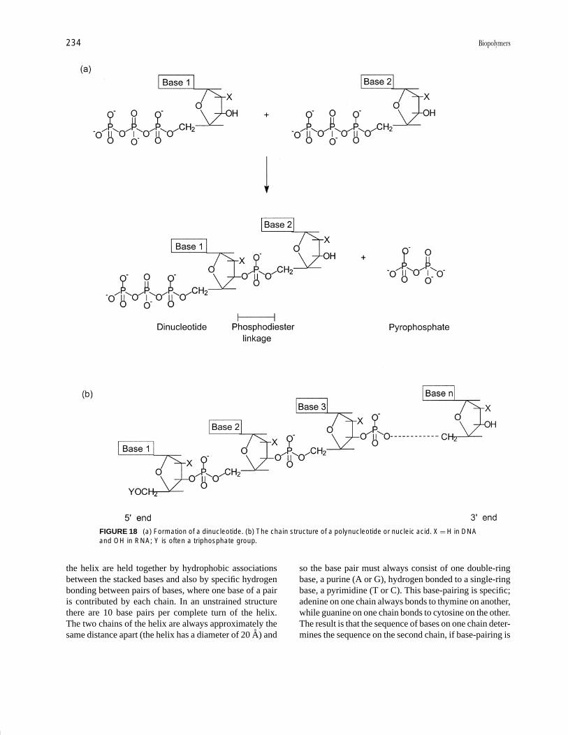
P1: FPP 2nd Revised Pages
Encyclopedia of Physical Science and Technology EN002C-64 May 19, 2001 20:39
234 Biopolymers
FIGURE 18 (a) Formation of a dinucleotide. (b) The chain structure of a polynucleotide or nucleic acid. X = H in DNAand OH in RNA; Y is often a triphosphate group.
the helix are held together by hydrophobic associationsbetween the stacked bases and also by specific hydrogenbonding between pairs of bases, where one base of a pairis contributed by each chain. In an unstrained structurethere are 10 base pairs per complete turn of the helix.The two chains of the helix are always approximately thesame distance apart (the helix has a diameter of 20 A) and
so the base pair must always consist of one double-ringbase, a purine (A or G), hydrogen bonded to a single-ringbase, a pyrimidine (T or C). This base-pairing is specific;adenine on one chain always bonds to thymine on another,while guanine on one chain bonds to cytosine on the other.The result is that the sequence of bases on one chain deter-mines the sequence on the second chain, if base-pairing is
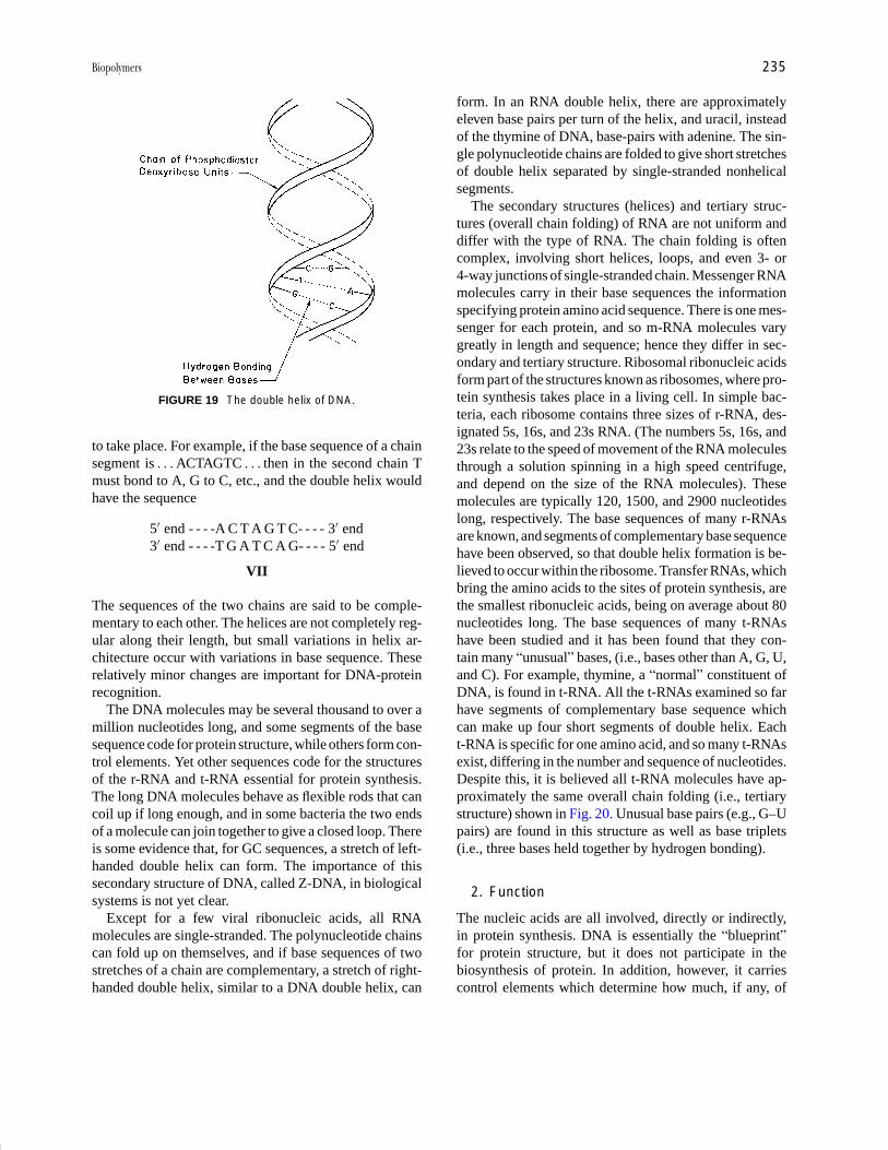
P1: FPP 2nd Revised Pages
Encyclopedia of Physical Science and Technology EN002C-64 May 19, 2001 20:39
Biopolymers 235
FIGURE 19 The double helix of DNA.
to take place. For example, if the base sequence of a chainsegment is . . . ACTAGTC . . . then in the second chain Tmust bond to A, G to C, etc., and the double helix wouldhave the sequence
5′ end - - - -A C T A G T C- - - - 3′ end3′ end - - - -T G A T C A G- - - - 5′ end
VII
The sequences of the two chains are said to be comple-mentary to each other. The helices are not completely reg-ular along their length, but small variations in helix ar-chitecture occur with variations in base sequence. Theserelatively minor changes are important for DNA-proteinrecognition.
The DNA molecules may be several thousand to over amillion nucleotides long, and some segments of the basesequence code for protein structure, while others form con-trol elements. Yet other sequences code for the structuresof the r-RNA and t-RNA essential for protein synthesis.The long DNA molecules behave as flexible rods that cancoil up if long enough, and in some bacteria the two endsof a molecule can join together to give a closed loop. Thereis some evidence that, for GC sequences, a stretch of left-handed double helix can form. The importance of thissecondary structure of DNA, called Z-DNA, in biologicalsystems is not yet clear.
Except for a few viral ribonucleic acids, all RNAmolecules are single-stranded. The polynucleotide chainscan fold up on themselves, and if base sequences of twostretches of a chain are complementary, a stretch of right-handed double helix, similar to a DNA double helix, can
form. In an RNA double helix, there are approximatelyeleven base pairs per turn of the helix, and uracil, insteadof the thymine of DNA, base-pairs with adenine. The sin-gle polynucleotide chains are folded to give short stretchesof double helix separated by single-stranded nonhelicalsegments.
The secondary structures (helices) and tertiary struc-tures (overall chain folding) of RNA are not uniform anddiffer with the type of RNA. The chain folding is oftencomplex, involving short helices, loops, and even 3- or4-way junctions of single-stranded chain. Messenger RNAmolecules carry in their base sequences the informationspecifying protein amino acid sequence. There is one mes-senger for each protein, and so m-RNA molecules varygreatly in length and sequence; hence they differ in sec-ondary and tertiary structure. Ribosomal ribonucleic acidsform part of the structures known as ribosomes, where pro-tein synthesis takes place in a living cell. In simple bac-teria, each ribosome contains three sizes of r-RNA, des-ignated 5s, 16s, and 23s RNA. (The numbers 5s, 16s, and23s relate to the speed of movement of the RNA moleculesthrough a solution spinning in a high speed centrifuge,and depend on the size of the RNA molecules). Thesemolecules are typically 120, 1500, and 2900 nucleotideslong, respectively. The base sequences of many r-RNAsare known, and segments of complementary base sequencehave been observed, so that double helix formation is be-lieved to occur within the ribosome. Transfer RNAs, whichbring the amino acids to the sites of protein synthesis, arethe smallest ribonucleic acids, being on average about 80nucleotides long. The base sequences of many t-RNAshave been studied and it has been found that they con-tain many “unusual” bases, (i.e., bases other than A, G, U,and C). For example, thymine, a “normal” constituent ofDNA, is found in t-RNA. All the t-RNAs examined so farhave segments of complementary base sequence whichcan make up four short segments of double helix. Eacht-RNA is specific for one amino acid, and so many t-RNAsexist, differing in the number and sequence of nucleotides.Despite this, it is believed all t-RNA molecules have ap-proximately the same overall chain folding (i.e., tertiarystructure) shown in Fig. 20. Unusual base pairs (e.g., G–Upairs) are found in this structure as well as base triplets(i.e., three bases held together by hydrogen bonding).
2. Function
The nucleic acids are all involved, directly or indirectly,in protein synthesis. DNA is essentially the “blueprint”for protein structure, but it does not participate in thebiosynthesis of protein. In addition, however, it carriescontrol elements which determine how much, if any, of
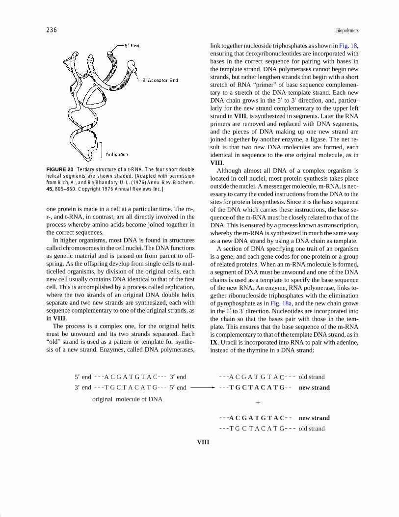
P1: FPP 2nd Revised Pages
Encyclopedia of Physical Science and Technology EN002C-64 May 19, 2001 20:39
236 Biopolymers
FIGURE 20 Tertiary structure of a t-RNA. The four short doublehelical segments are shown shaded. [Adapted with permissionfrom Rich, A., and RajBhandary, U. L. (1976) Annu. Rev. Biochem.45, 805–860. Copyright 1976 Annual Reviews Inc.]
one protein is made in a cell at a particular time. The m-,r-, and t-RNA, in contrast, are all directly involved in theprocess whereby amino acids become joined together inthe correct sequences.
In higher organisms, most DNA is found in structurescalled chromosomes in the cell nuclei. The DNA functionsas genetic material and is passed on from parent to off-spring. As the offspring develop from single cells to mul-ticelled organisms, by division of the original cells, eachnew cell usually contains DNA identical to that of the firstcell. This is accomplished by a process called replication,where the two strands of an original DNA double helixseparate and two new strands are synthesized, each withsequence complementary to one of the original strands, asin VIII.
The process is a complex one, for the original helixmust be unwound and its two strands separated. Each“old” strand is used as a pattern or template for synthe-sis of a new strand. Enzymes, called DNA polymerases,
VIII
5′3′
end
end
3′5′
end
end
A C G A T G T A C
T G C T A C A T G
old strand
new strand
A C G A T G T A
T G C T A C A T G
new strand
old strand
A C G A T G T A C
T G C T A C A T G
original molecule of DNA�
C
link together nucleoside triphosphates as shown in Fig. 18,ensuring that deoxyribonucleotides are incorporated withbases in the correct sequence for pairing with bases inthe template strand. DNA polymerases cannot begin newstrands, but rather lengthen strands that begin with a shortstretch of RNA “primer” of base sequence complemen-tary to a stretch of the DNA template strand. Each newDNA chain grows in the 5′ to 3′ direction, and, particu-larly for the new strand complementary to the upper leftstrand in VIII, is synthesized in segments. Later the RNAprimers are removed and replaced with DNA segments,and the pieces of DNA making up one new strand arejoined together by another enzyme, a ligase. The net re-sult is that two new DNA molecules are formed, eachidentical in sequence to the one original molecule, as inVIII.
Although almost all DNA of a complex organism islocated in cell nuclei, most protein synthesis takes placeoutside the nuclei. A messenger molecule, m-RNA, is nec-essary to carry the coded instructions from the DNA to thesites for protein biosynthesis. Since it is the base sequenceof the DNA which carries these instructions, the base se-quence of the m-RNA must be closely related to that of theDNA. This is ensured by a process known as transcription,whereby the m-RNA is synthesized in much the same wayas a new DNA strand by using a DNA chain as template.
A section of DNA specifying one trait of an organismis a gene, and each gene codes for one protein or a groupof related proteins. When an m-RNA molecule is formed,a segment of DNA must be unwound and one of the DNAchains is used as a template to specify the base sequenceof the new RNA. An enzyme, RNA polymerase, links to-gether ribonucleoside triphosphates with the eliminationof pyrophosphate as in Fig. 18a, and the new chain growsin the 5′ to 3′ direction. Nucleotides are incorporated intothe chain so that the bases pair with those in the tem-plate. This ensures that the base sequence of the m-RNAis complementary to that of the template DNA strand, as inIX. Uracil is incorporated into RNA to pair with adenine,instead of the thymine in a DNA strand:
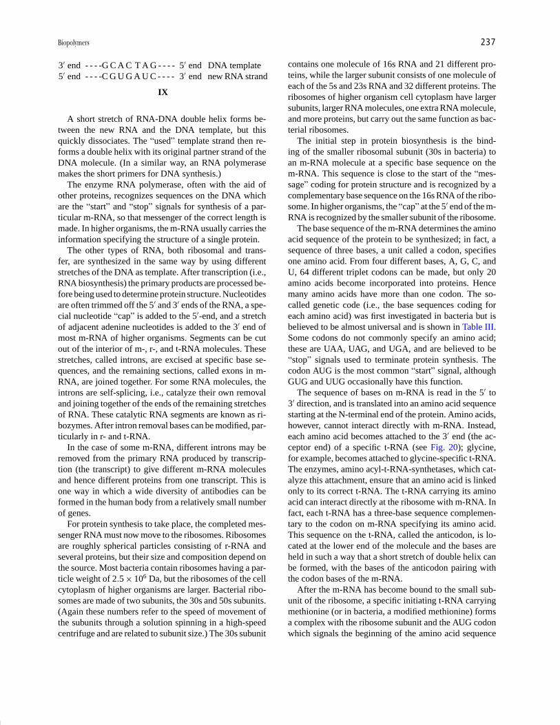
P1: FPP 2nd Revised Pages
Encyclopedia of Physical Science and Technology EN002C-64 May 19, 2001 20:39
Biopolymers 237
3′ end - - - -G C A C T A G - - - - 5′ end DNA template5′ end - - - -C G U G A U C - - - - 3′ end new RNA strand
IX
A short stretch of RNA-DNA double helix forms be-tween the new RNA and the DNA template, but thisquickly dissociates. The “used” template strand then re-forms a double helix with its original partner strand of theDNA molecule. (In a similar way, an RNA polymerasemakes the short primers for DNA synthesis.)
The enzyme RNA polymerase, often with the aid ofother proteins, recognizes sequences on the DNA whichare the “start” and “stop” signals for synthesis of a par-ticular m-RNA, so that messenger of the correct length ismade. In higher organisms, the m-RNA usually carries theinformation specifying the structure of a single protein.
The other types of RNA, both ribosomal and trans-fer, are synthesized in the same way by using differentstretches of the DNA as template. After transcription (i.e.,RNA biosynthesis) the primary products are processed be-fore being used to determine protein structure. Nucleotidesare often trimmed off the 5′ and 3′ ends of the RNA, a spe-cial nucleotide “cap” is added to the 5′-end, and a stretchof adjacent adenine nucleotides is added to the 3′ end ofmost m-RNA of higher organisms. Segments can be cutout of the interior of m-, r-, and t-RNA molecules. Thesestretches, called introns, are excised at specific base se-quences, and the remaining sections, called exons in m-RNA, are joined together. For some RNA molecules, theintrons are self-splicing, i.e., catalyze their own removaland joining together of the ends of the remaining stretchesof RNA. These catalytic RNA segments are known as ri-bozymes. After intron removal bases can be modified, par-ticularly in r- and t-RNA.
In the case of some m-RNA, different introns may beremoved from the primary RNA produced by transcrip-tion (the transcript) to give different m-RNA moleculesand hence different proteins from one transcript. This isone way in which a wide diversity of antibodies can beformed in the human body from a relatively small numberof genes.
For protein synthesis to take place, the completed mes-senger RNA must now move to the ribosomes. Ribosomesare roughly spherical particles consisting of r-RNA andseveral proteins, but their size and composition depend onthe source. Most bacteria contain ribosomes having a par-ticle weight of 2.5 × 10⁶ Da, but the ribosomes of the cellcytoplasm of higher organisms are larger. Bacterial ribo-somes are made of two subunits, the 30s and 50s subunits.(Again these numbers refer to the speed of movement ofthe subunits through a solution spinning in a high-speedcentrifuge and are related to subunit size.) The 30s subunit
contains one molecule of 16s RNA and 21 different pro-teins, while the larger subunit consists of one molecule ofeach of the 5s and 23s RNA and 32 different proteins. Theribosomes of higher organism cell cytoplasm have largersubunits, larger RNA molecules, one extra RNA molecule,and more proteins, but carry out the same function as bac-terial ribosomes.
The initial step in protein biosynthesis is the bind-ing of the smaller ribosomal subunit (30s in bacteria) toan m-RNA molecule at a specific base sequence on them-RNA. This sequence is close to the start of the “mes-sage” coding for protein structure and is recognized by acomplementary base sequence on the 16s RNA of the ribo-some. In higher organisms, the “cap” at the 5′ end of the m-RNA is recognized by the smaller subunit of the ribosome.
The base sequence of the m-RNA determines the aminoacid sequence of the protein to be synthesized; in fact, asequence of three bases, a unit called a codon, specifiesone amino acid. From four different bases, A, G, C, andU, 64 different triplet codons can be made, but only 20amino acids become incorporated into proteins. Hencemany amino acids have more than one codon. The so-called genetic code (i.e., the base sequences coding foreach amino acid) was first investigated in bacteria but isbelieved to be almost universal and is shown in Table III.Some codons do not commonly specify an amino acid;these are UAA, UAG, and UGA, and are believed to be“stop” signals used to terminate protein synthesis. Thecodon AUG is the most common “start” signal, althoughGUG and UUG occasionally have this function.
The sequence of bases on m-RNA is read in the 5′ to3′ direction, and is translated into an amino acid sequencestarting at the N-terminal end of the protein. Amino acids,however, cannot interact directly with m-RNA. Instead,each amino acid becomes attached to the 3′ end (the ac-ceptor end) of a specific t-RNA (see Fig. 20); glycine,for example, becomes attached to glycine-specific t-RNA.The enzymes, amino acyl-t-RNA-synthetases, which cat-alyze this attachment, ensure that an amino acid is linkedonly to its correct t-RNA. The t-RNA carrying its aminoacid can interact directly at the ribosome with m-RNA. Infact, each t-RNA has a three-base sequence complemen-tary to the codon on m-RNA specifying its amino acid.This sequence on the t-RNA, called the anticodon, is lo-cated at the lower end of the molecule and the bases areheld in such a way that a short stretch of double helix canbe formed, with the bases of the anticodon pairing withthe codon bases of the m-RNA.
After the m-RNA has become bound to the small sub-unit of the ribosome, a specific initiating t-RNA carryingmethionine (or in bacteria, a modified methionine) formsa complex with the ribosome subunit and the AUG codonwhich signals the beginning of the amino acid sequence
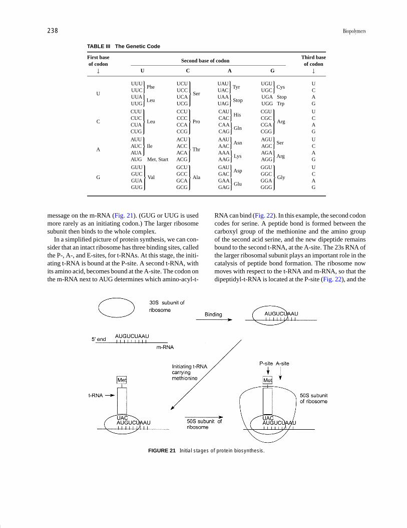
P1: FPP 2nd Revised Pages
Encyclopedia of Physical Science and Technology EN002C-64 May 19, 2001 20:39
238 Biopolymers
TABLE III The Genetic Code
First base Third baseSecond base of codon
of codon of codon↓ U C A G ↓
U
UUUUUC
}Phe
UUAUUG
}Leu
UCUUCCUCAUCG
Ser
UAUUAC
}Tyr
UAAUAG
}Stop
UGUUGC
}Cys
UGA StopUGG Trp
UCAG
C
CUUCUCCUACUG
Leu
CCUCCCCCACCG
Pro
CAUCAC
}His
CAACAG
}Gln
CGUCGCCGACGG
Arg
UCAG
A
AUUAUCAUA
Ile
AUG Met, Start
ACUACCACAACG
Thr
AAUAAC
}Asn
AAAAAG
}Lys
AGUAGC
}Ser
AGAAGG
}Arg
UCAG
G
GUUGUCGUAGUG
Val
GCUGCCGCAGCG
Ala
GAUGAC
}Asp
GAAGAG
}Glu
GGUGGCGGAGGG
Gly
UCAG
message on the m-RNA (Fig. 21). (GUG or UUG is usedmore rarely as an initiating codon.) The larger ribosomesubunit then binds to the whole complex.
In a simplified picture of protein synthesis, we can con-sider that an intact ribosome has three binding sites, calledthe P-, A-, and E-sites, for t-RNAs. At this stage, the initi-ating t-RNA is bound at the P-site. A second t-RNA, withits amino acid, becomes bound at the A-site. The codon onthe m-RNA next to AUG determines which amino-acyl-t-
FIGURE 21 Initial stages of protein biosynthesis.
RNA can bind (Fig. 22). In this example, the second codoncodes for serine. A peptide bond is formed between thecarboxyl group of the methionine and the amino groupof the second acid serine, and the new dipeptide remainsbound to the second t-RNA, at the A-site. The 23s RNA ofthe larger ribosomal subunit plays an important role in thecatalysis of peptide bond formation. The ribosome nowmoves with respect to the t-RNA and m-RNA, so that thedipeptidyl-t-RNA is located at the P-site (Fig. 22), and the

P1: FPP 2nd Revised Pages
Encyclopedia of Physical Science and Technology EN002C-64 May 19, 2001 20:39
Biopolymers 239
FIGURE 22 Elongation of a peptide chain. (I, on the serine t-RNA, signifies inosine, a base similar in structure toguanine, but lacking the NH2 group. Inosine is common at t-RNA anticodons, and can pair with U, C, or A on a codon.)
free t-RNA moves to the E-site. A shape change at the ri-bosome surface and binding of a new amino-acyl-t-RNAat the A site cause the free t-RNA to drop out of the E-site.The processes shown in Fig. 22 can now be repeated overand over, to give a growing polypeptide chain. In this case,the third amino acid to be joined to the protein would beasparagine.
A ribosome moves along the m-RNA until a terminatorcodon appears at the A-site. The completed polypeptidechain is released from the last t-RNA, the t-RNA dissoci-ates from the ribosome, and the ribosome itself splits intotwo subunits ready to recommence protein synthesis.
The whole process, whereby a sequence of bases on m-RNA becomes an amino acid sequence of a polypeptidechain, is called translation, and is much more complexthan presented here. The ribosome plays an active part inthe process and minor changes in its structure may occurat more than one stage of protein synthesis. Ribosomestructure is more complicated than depicted in Figs. 21 and22; a cavity exists between the two subunits in the intactribosome, and it is in this cavity that the t-RNAs can bind.In addition, many protein factors are involved in protein
synthesis to help ensure correct initiation, elongation, andtermination of the chain. After synthesis, many proteinsundergo further modifications—amino acid side chainsmay be altered, segments of polypeptide chain may beremoved, or prosthetic groups may be added.
Protein biosynthesis must at all times be under strictcontrol. Much of this control, particularly in bacteria, isexerted at the level of transcription (i.e., production ofm-RNA). In some cases, a protein known as a repres-sor recognizes and binds to a segment of DNA close toa site for initiation of m-RNA synthesis. The repressorbinds in the grooves of the DNA helix and effectively pre-vents biosynthesis of the m-RNA. When that m-RNA isrequired, a shape-change can be brought about in the re-pressor protein by another molecule called an inducer; therepressor no longer binds to the DNA and transcription ofm-RNA can take place. In other instances, specific proteinscan bind to DNA and enhance the synthesis of particularm-RNA molecules. Translational control is also possible.Alterations in protein initiation factors or binding of pro-teins to m-RNA to alter its secondary structure or maskthe initial ribosome recognition site can change the amount
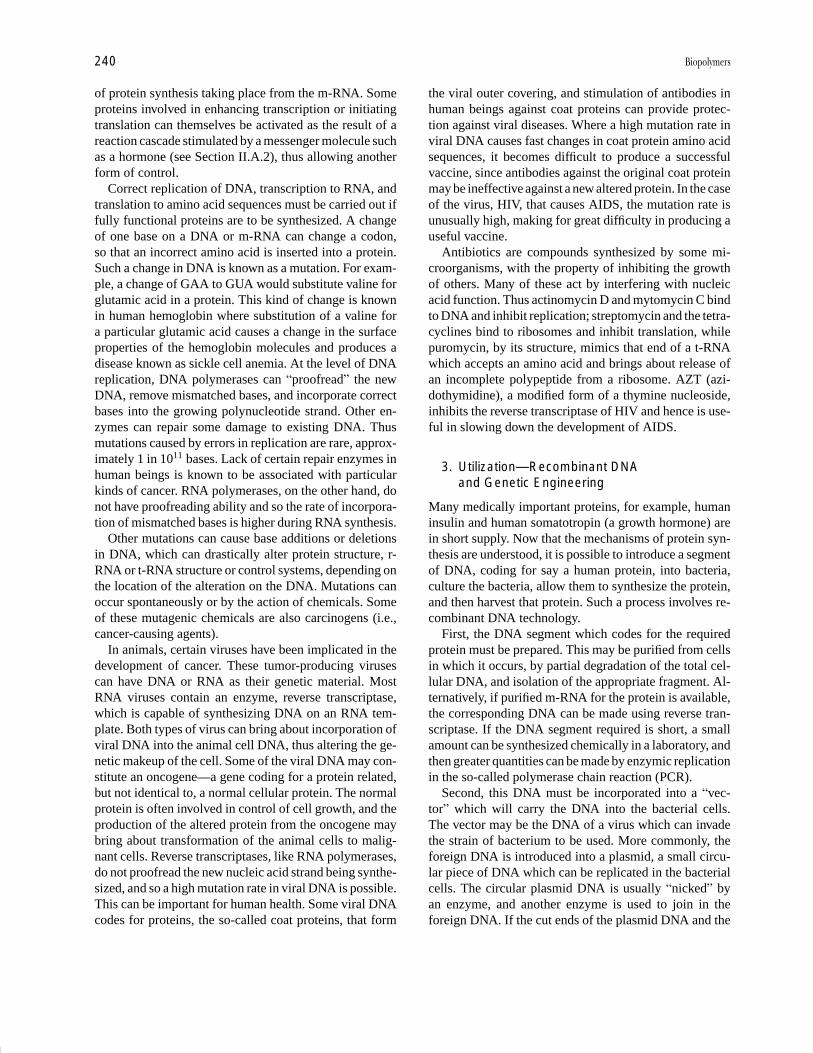
P1: FPP 2nd Revised Pages
Encyclopedia of Physical Science and Technology EN002C-64 May 19, 2001 20:39
240 Biopolymers
of protein synthesis taking place from the m-RNA. Someproteins involved in enhancing transcription or initiatingtranslation can themselves be activated as the result of areaction cascade stimulated by a messenger molecule suchas a hormone (see Section II.A.2), thus allowing anotherform of control.
Correct replication of DNA, transcription to RNA, andtranslation to amino acid sequences must be carried out iffully functional proteins are to be synthesized. A changeof one base on a DNA or m-RNA can change a codon,so that an incorrect amino acid is inserted into a protein.Such a change in DNA is known as a mutation. For exam-ple, a change of GAA to GUA would substitute valine forglutamic acid in a protein. This kind of change is knownin human hemoglobin where substitution of a valine fora particular glutamic acid causes a change in the surfaceproperties of the hemoglobin molecules and produces adisease known as sickle cell anemia. At the level of DNAreplication, DNA polymerases can “proofread” the newDNA, remove mismatched bases, and incorporate correctbases into the growing polynucleotide strand. Other en-zymes can repair some damage to existing DNA. Thusmutations caused by errors in replication are rare, approx-imately 1 in 1011 bases. Lack of certain repair enzymes inhuman beings is known to be associated with particularkinds of cancer. RNA polymerases, on the other hand, donot have proofreading ability and so the rate of incorpora-tion of mismatched bases is higher during RNA synthesis.
Other mutations can cause base additions or deletionsin DNA, which can drastically alter protein structure, r-RNA or t-RNA structure or control systems, depending onthe location of the alteration on the DNA. Mutations canoccur spontaneously or by the action of chemicals. Someof these mutagenic chemicals are also carcinogens (i.e.,cancer-causing agents).
In animals, certain viruses have been implicated in thedevelopment of cancer. These tumor-producing virusescan have DNA or RNA as their genetic material. MostRNA viruses contain an enzyme, reverse transcriptase,which is capable of synthesizing DNA on an RNA tem-plate. Both types of virus can bring about incorporation ofviral DNA into the animal cell DNA, thus altering the ge-netic makeup of the cell. Some of the viral DNA may con-stitute an oncogene—a gene coding for a protein related,but not identical to, a normal cellular protein. The normalprotein is often involved in control of cell growth, and theproduction of the altered protein from the oncogene maybring about transformation of the animal cells to malig-nant cells. Reverse transcriptases, like RNA polymerases,do not proofread the new nucleic acid strand being synthe-sized, and so a high mutation rate in viral DNA is possible.This can be important for human health. Some viral DNAcodes for proteins, the so-called coat proteins, that form
the viral outer covering, and stimulation of antibodies inhuman beings against coat proteins can provide protec-tion against viral diseases. Where a high mutation rate inviral DNA causes fast changes in coat protein amino acidsequences, it becomes difficult to produce a successfulvaccine, since antibodies against the original coat proteinmay be ineffective against a new altered protein. In the caseof the virus, HIV, that causes AIDS, the mutation rate isunusually high, making for great difficulty in producing auseful vaccine.
Antibiotics are compounds synthesized by some mi-croorganisms, with the property of inhibiting the growthof others. Many of these act by interfering with nucleicacid function. Thus actinomycin D and mytomycin C bindto DNA and inhibit replication; streptomycin and the tetra-cyclines bind to ribosomes and inhibit translation, whilepuromycin, by its structure, mimics that end of a t-RNAwhich accepts an amino acid and brings about release ofan incomplete polypeptide from a ribosome. AZT (azi-dothymidine), a modified form of a thymine nucleoside,inhibits the reverse transcriptase of HIV and hence is use-ful in slowing down the development of AIDS.
3. Utilization—Recombinant DNAand Genetic Engineering
Many medically important proteins, for example, humaninsulin and human somatotropin (a growth hormone) arein short supply. Now that the mechanisms of protein syn-thesis are understood, it is possible to introduce a segmentof DNA, coding for say a human protein, into bacteria,culture the bacteria, allow them to synthesize the protein,and then harvest that protein. Such a process involves re-combinant DNA technology.
First, the DNA segment which codes for the requiredprotein must be prepared. This may be purified from cellsin which it occurs, by partial degradation of the total cel-lular DNA, and isolation of the appropriate fragment. Al-ternatively, if purified m-RNA for the protein is available,the corresponding DNA can be made using reverse tran-scriptase. If the DNA segment required is short, a smallamount can be synthesized chemically in a laboratory, andthen greater quantities can be made by enzymic replicationin the so-called polymerase chain reaction (PCR).
Second, this DNA must be incorporated into a “vec-tor” which will carry the DNA into the bacterial cells.The vector may be the DNA of a virus which can invadethe strain of bacterium to be used. More commonly, theforeign DNA is introduced into a plasmid, a small circu-lar piece of DNA which can be replicated in the bacterialcells. The circular plasmid DNA is usually “nicked” byan enzyme, and another enzyme is used to join in theforeign DNA. If the cut ends of the plasmid DNA and the
P1: FPP 2nd Revised Pages
Encyclopedia of Physical Science and Technology EN002C-64 May 19, 2001 20:39
Biopolymers 241
foreign DNA have complementary sequences, then correctcombination of the two is easier. These so-called “sticky”ends can be produced by enzymes or chemical synthe-sis. The product—an artificial combination of bacterialplasmid DNA and, for example, human DNA—is calledrecombinant DNA.
The plasmid is then introduced into a bacterial cell andthe bacterium is cloned (i.e., the cell is allowed to divideseveral times) producing progeny bacteria with the samegenetic constitution as the original cell. Each cell carriesthe DNA coding for the required protein, and if the DNAhas been inserted with the correct control elements, eachcell synthesizes the protein. The protein can later be puri-fied from the bacterial culture.
In this way it has been possible to produce human in-sulin, growth hormone, and interferon (an antiviral pro-tein) from E. coli—a common bacterium in the humandigestive tract.
Fears that new and dangerous strains of E. coli mightresult from recombinant DNA experiments have mostlybeen allayed by stringent controls on the kinds of experi-ments that can be carried out and by greater understandingof the control mechanisms involved in bacterial nucleicacid metabolism.
It is hoped by these methods to produce medically use-ful proteins cheaply and on a large scale. In addition, newbacteria with useful properties may be “created” (e.g., bac-teria able to convert cellulose to methane for energy pro-duction). (At present two different microorganisms mustbe used—one converts cellulose to acids, the second theseacids to methane.)
By incorporating DNA with specific base changes intobacteria it is possible to obtain proteins with as littleas one altered amino acid. This process, known as site-directed mutagenesis, has enabled detailed investigationsto be made of the role of individual amino acids in, forexample, enzyme activity and stability. It is hoped that, inthe future, industrially important enzymes with improvedthermal stability may be made in this way.
Genetic engineering can also be carried out on plantsand animals, although there is usually some difficulty inintroducing the new DNA into the plant or animal celland ensuring that it is used to code for a new protein.Single plant cells can be transformed by infection with abacterium, Agrobacterium tumefaciens, carrying a plas-mid that contains the desired new DNA. When the bac-terium contacts a plant cell, some of the plasmid DNA istransferred to the plant cell nucleus and is integrated intothe plant cell’s DNA. Then whole plants can be producedfrom the single plant cells in culture by the administra-tion of hormones. Thus, it is possible to grow completeplants with an altered genetic makeup. Disease resistancecan be improved, for example, by incorporating a gene
for a virus coat protein into a plant. This appears to stopthe virus replicating in the plant. The first commerciallygrown genetically modified plants contain DNA codingfor an enzyme that confers herbicide resistance or for pro-teins that are insecticidal. In the first case, less herbicideneed be used on crops to kill weeds, as spraying can becarried out when both the weeds and crop plants are well-grown. In the second case, application of external pesti-cide may not be required, since the crop plants themselves,containing the new insecticidal protein, may kill invadinginsects. Currently, cotton, soya, maize, and canola contain-ing these modifications are grown commercially, but be-cause of concerns about possible environmental problemssuch as potential harm to beneficial insects, introduction ofnew genetically-engineered crop plants has slowed down.
An extension of this work could lead to “genetic en-gineering” in human beings, where genetic diseases (i.e.,diseases caused by a defective or missing enzyme) mightbe cured by incorporation of DNA coding for that pro-tein. It will be difficult, however, to ensure that subsequentbiosynthesis of the protein is under correct control, so thatthe protein is made in the right amounts in the appropriatetissues.
Small amounts of human DNA found at the scene ofa crime can now be amplified by PCR technology, andthe DNA can be hydrolyzed by enzymes specific for par-ticular base sequences. Because the pattern of fragmentsproduced is believed to be characteristic of one humanindividual, the process is now used to help identify perpe-trators of serious crimes.
D. Rubber, Lignin, and Polyesters
Rubber is a hydrocarbon polymer produced by many trop-ical and a few temperate plants, such as the dandelion.Commercially, rubber is obtained from a tree originallyfound in Brazil, Hevea brasiliensis, which is now grownextensively in southeast Asia and Africa, as well as Cen-tral and South America. Rubber is obtained from the treein the form of latex, a suspension of polymer particles ina slightly viscous aqueous solution; this latex oozes fromthe tree when a cut is made in the bark. Trees may betapped again and again for more than 30 years, and com-mercial yields can be more than 3300 pounds per acre peryear (3600 kg/ha/yr).
The monomer of rubber is isopentenyl pyrophosphate,and when the polymer is synthesized, the monomers be-come linked together, with the elimination of pyrophos-phate, as in Fig. 23. During the joining of the monomerresidues, the carbon-carbon double bond changes position(from left of the CH3 group, to right of it) and the repeatunit in the polymer is an isoprene unit; rubber is, thus,a polyisoprene. In latex, the polyisoprene molecules are
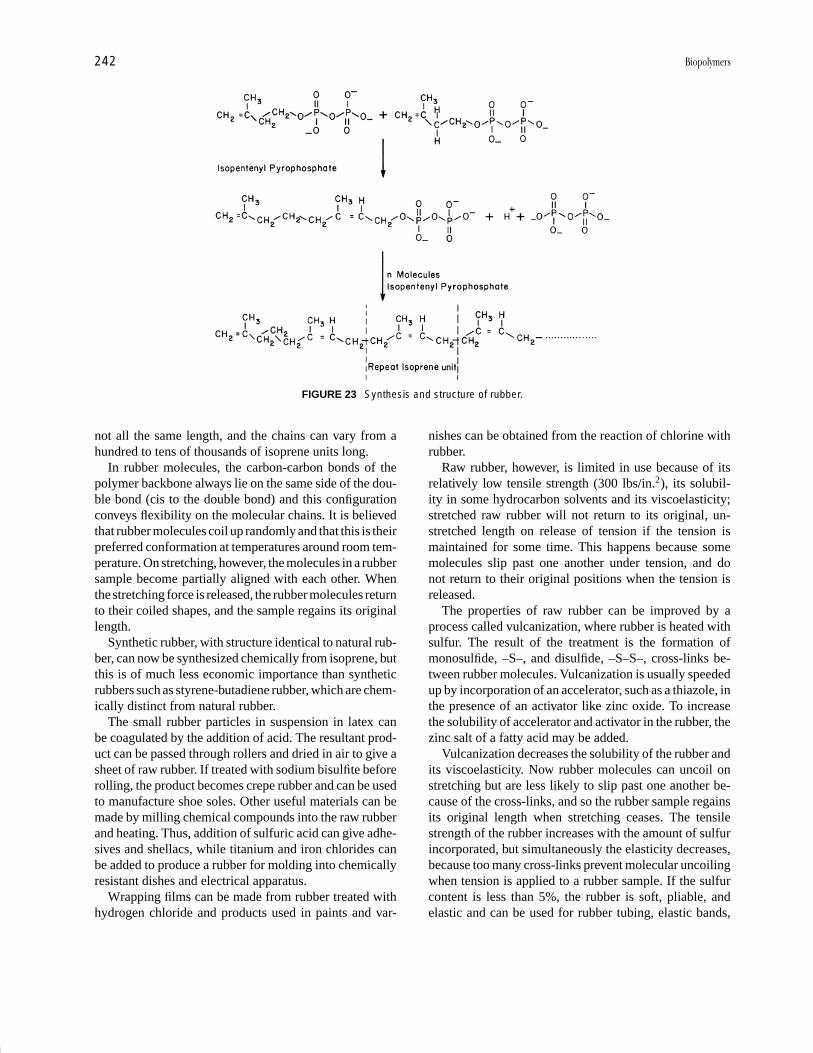
P1: FPP 2nd Revised Pages
Encyclopedia of Physical Science and Technology EN002C-64 May 19, 2001 20:39
242 Biopolymers
FIGURE 23 Synthesis and structure of rubber.
not all the same length, and the chains can vary from ahundred to tens of thousands of isoprene units long.
In rubber molecules, the carbon-carbon bonds of thepolymer backbone always lie on the same side of the dou-ble bond (cis to the double bond) and this configurationconveys flexibility on the molecular chains. It is believedthat rubber molecules coil up randomly and that this is theirpreferred conformation at temperatures around room tem-perature. On stretching, however, the molecules in a rubbersample become partially aligned with each other. Whenthe stretching force is released, the rubber molecules returnto their coiled shapes, and the sample regains its originallength.
Synthetic rubber, with structure identical to natural rub-ber, can now be synthesized chemically from isoprene, butthis is of much less economic importance than syntheticrubbers such as styrene-butadiene rubber, which are chem-ically distinct from natural rubber.
The small rubber particles in suspension in latex canbe coagulated by the addition of acid. The resultant prod-uct can be passed through rollers and dried in air to give asheet of raw rubber. If treated with sodium bisulfite beforerolling, the product becomes crepe rubber and can be usedto manufacture shoe soles. Other useful materials can bemade by milling chemical compounds into the raw rubberand heating. Thus, addition of sulfuric acid can give adhe-sives and shellacs, while titanium and iron chlorides canbe added to produce a rubber for molding into chemicallyresistant dishes and electrical apparatus.
Wrapping films can be made from rubber treated withhydrogen chloride and products used in paints and var-
nishes can be obtained from the reaction of chlorine withrubber.
Raw rubber, however, is limited in use because of itsrelatively low tensile strength (300 lbs/in.2), its solubil-ity in some hydrocarbon solvents and its viscoelasticity;stretched raw rubber will not return to its original, un-stretched length on release of tension if the tension ismaintained for some time. This happens because somemolecules slip past one another under tension, and donot return to their original positions when the tension isreleased.
The properties of raw rubber can be improved by aprocess called vulcanization, where rubber is heated withsulfur. The result of the treatment is the formation ofmonosulfide, –S–, and disulfide, –S–S–, cross-links be-tween rubber molecules. Vulcanization is usually speededup by incorporation of an accelerator, such as a thiazole, inthe presence of an activator like zinc oxide. To increasethe solubility of accelerator and activator in the rubber, thezinc salt of a fatty acid may be added.
Vulcanization decreases the solubility of the rubber andits viscoelasticity. Now rubber molecules can uncoil onstretching but are less likely to slip past one another be-cause of the cross-links, and so the rubber sample regainsits original length when stretching ceases. The tensilestrength of the rubber increases with the amount of sulfurincorporated, but simultaneously the elasticity decreases,because too many cross-links prevent molecular uncoilingwhen tension is applied to a rubber sample. If the sulfurcontent is less than 5%, the rubber is soft, pliable, andelastic and can be used for rubber tubing, elastic bands,
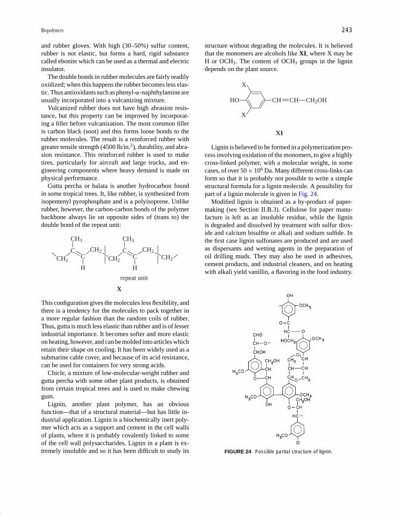
P1: FPP 2nd Revised Pages
Encyclopedia of Physical Science and Technology EN002C-64 May 19, 2001 20:39
Biopolymers 243
and rubber gloves. With high (30–50%) sulfur content,rubber is not elastic, but forms a hard, rigid substancecalled ebonite which can be used as a thermal and electricinsulator.
The double bonds in rubber molecules are fairly readilyoxidized; when this happens the rubber becomes less elas-tic. Thus antioxidants such as phenyl-α-naphthylamine areusually incorporated into a vulcanizing mixture.
Vulcanized rubber does not have high abrasion resis-tance, but this property can be improved by incorporat-ing a filler before vulcanization. The most common filleris carbon black (soot) and this forms loose bonds to therubber molecules. The result is a reinforced rubber withgreater tensile strength (4500 lb/in.2), durability, and abra-sion resistance. This reinforced rubber is used to maketires, particularly for aircraft and large trucks, and en-gineering components where heavy demand is made onphysical performance.
Gutta percha or balata is another hydrocarbon foundin some tropical trees. It, like rubber, is synthesized fromisopentenyl pyrophosphate and is a polyisoprene. Unlikerubber, however, the carbon-carbon bonds of the polymerbackbone always lie on opposite sides of (trans to) thedouble bond of the repeat unit:
X
CH2
C
CH3
C
H
CH2
CH2
CC
CH3
CH2
H
CH2
repeat unit
This configuration gives the molecules less flexibility, andthere is a tendency for the molecules to pack together ina more regular fashion than the random coils of rubber.Thus, gutta is much less elastic than rubber and is of lesserindustrial importance. It becomes softer and more elasticon heating, however, and can be molded into articles whichretain their shape on cooling. It has been widely used as asubmarine cable cover, and because of its acid resistance,can be used for containers for very strong acids.
Chicle, a mixture of low-molecular-weight rubber andgutta percha with some other plant products, is obtainedfrom certain tropical trees and is used to make chewinggum.
Lignin, another plant polymer, has an obviousfunction—that of a structural material—but has little in-dustrial application. Lignin is a biochemically inert poly-mer which acts as a support and cement in the cell wallsof plants, where it is probably covalently linked to someof the cell wall polysaccharides. Lignin in a plant is ex-tremely insoluble and so it has been difficult to study its
structure without degrading the molecules. It is believedthat the monomers are alcohols like XI, where X may beH or OCH3. The content of OCH3 groups in the lignindepends on the plant source.
XI
HO CH CH CH2OH
X
X
Lignin is believed to be formed in a polymerization pro-cess involving oxidation of the monomers, to give a highlycross-linked polymer, with a molecular weight, in somecases, of over 50 × 106 Da. Many different cross-links canform so that it is probably not possible to write a simplestructural formula for a lignin molecule. A possibility forpart of a lignin molecule is given in Fig. 24.
Modified lignin is obtained as a by-product of paper-making (see Section II.B.3). Cellulose for paper manu-facture is left as an insoluble residue, while the ligninis degraded and dissolved by treatment with sulfur diox-ide and calcium bisulfite or alkali and sodium sulfide. Inthe first case lignin sulfonates are produced and are usedas dispersants and wetting agents in the preparation ofoil drilling muds. They may also be used in adhesives,cement products, and industrial cleaners, and on heatingwith alkali yield vanillin, a flavoring in the food industry.
FIGURE 24 Possible partial structure of lignin.

P1: FPP 2nd Revised Pages
Encyclopedia of Physical Science and Technology EN002C-64 May 19, 2001 20:39
244 Biopolymers
Lignin from alkali extraction of wood is a stabilizer andemulsifying agent, an additive for concrete, and a filler fornatural rubber. Much less lignin is used, however, than isproduced by the paper industry and some is simply burntas a fuel.
Cutin and suberin are polymers that provide physicalbarriers in plants to prevent or control diffusion of waterand other small molecules. Leaves of plants are protectedby a cuticle of cutin embedded in waxes, while under-ground organs such as roots have a barrier layer contain-ing suberin and waxes. The monomers of both are thoughtto be a variety of hydroxy acids such as XII:
XII
CH2OH (CH2)7 (CHOH)2 (CH2)7 COOH
Trihydroxy acids, such as the above, are found more fre-quently in cutin than in suberin. In suberin, acids contain-ing only one hydroxyl group at the end of the moleculeor di-acids with a COOH group at each end are muchmore common. Both polymers contain some monomerresidues related to those of lignin (with structures likeXI, but having a COOH group instead of CH2OH at theend of the side-chain); suberin can contain up to 60% ofthese residues, while cutin contains much less. The acidmonomers probably become linked together by reactionbetween the COOH of one monomer and OH of anotherto give ester linkages as in XIII:
XIII
COOH HO COO H2O� �
The molecules are highly cross-linked and, like lignin,cannot be described by a single simple repeat unit. Some ofthe phenolic residues of suberin may be covalently linkedto cell wall polysaccharides. While both polymers have aprotective function, break-down products from cutin mayalso be important for activating defense mechanisms whenplants are invaded by pathogens.
Most commercial plastics are made from petrochemi-cals and are nonbiodegradable. Problems of supply maydevelop in the future as oil stocks run low, and the lack ofdegradability can currently result in environmental pol-lution when plastic objects are discarded. Thus investi-gations are ongoing to find materials that can be pro-duced from renewable resources and are biodegradable,but have the properties of synthetic polymer thermoplas-tics or elastomers. Some bacteria synthesize polyesters,the poly(hydroxyalkanoates), with these properties. Themonomers are usually of the type shown in XIV, where nis often 0 or 1.
XIV
HO CH CH2COOH
(CH2)n
CH3
The monomers become linked together essentially asin XIII, and the bacteria use the polymers as energy re-serves. The most common polymer, poly(3-hydroxy bu-tyrate) made from XIV where n = 0, resembles polypropy-lene in properties, but is stiffer and more brittle. A moreuseful polyester is a random copolymer of 3-hydroxy bu-tyrate (XIV where n = 0) and 3-hydroxy valerate (XIVwhere n = 1), and is tougher and more flexible. This canbe molded and is made into bottles and containers. Films,coatings for paper and board, and compost bags can alsobe produced from the copolymer. Polymers of longerchain acids (XIV with n = 4 for example) are rubberyand elastic, and may in future find uses as biodegrad-able elastomers. The poly(hydroxyalkanoates) are readilydegraded to water and carbon dioxide, or in some casesmethane, by enzyme systems occurring in bacteria of soil,sewage sludge, or compost. At present, however, the highcost of production of these polyesters limits their use. Re-search is under way to produce bacteria “engineered” (bytransferring genes from one bacterium to another) to syn-thesize the polymers more efficiently from cheap carbonsources such as sugar cane and beet molasses, cheese wheyand hydrolysates of starch, and hemicellulose (see Sec-tion II.B.3). New poly(hydroxyalkanoates), produced bysupplying bacteria with a variety of acid starting materials,are also being investigated. In addition, attempts are beingmade to transfer the bacterial genes for polyester synthesisto plants, where the sun’s energy, trapped via photosynthe-sis, could be utilized for poly(hydroxyalkanoate) produc-tion, thus lowering costs compared to expenditure on thebacterial fermentations currently necessary for polymerformation.
E. Polymer-Polymer Interactions
For very many biopolymers, their importance in the liv-ing organism lies in the way in which they interact withother polymers. In a few cases there is covalent bondingbetween polymers, for example, in the proteoglycans ofanimal connective tissue (see Section II.B.7), or betweenlignin and polysaccharides in plant cell walls. In manymore instances, however, interactions are noncovalent andinvolve weaker bonds, such as hydrogen or ionic bondingor hydrophobic associations. Although the bonding is rel-atively weak, the interactions can be strong, because anarea of the surface of one polymer molecule fits exactly
P1: FPP 2nd Revised Pages
Encyclopedia of Physical Science and Technology EN002C-64 May 19, 2001 20:39
Biopolymers 245
(sometimes after minor conformational changes) onto thesurface of another.
Proteins, in particular, must be able to interact withother polymers, for enzymes are involved in the synthesisand degradation of all biopolymers. In addition, however,many examples are known of associations between nonen-zymic proteins and other proteins, polysaccharides, or nu-cleic acids. Muscle movement, for example, is broughtabout and controlled by complex interactions between sev-eral proteins (myosin, actin, troponin, and tropomyosin)while collagen fibers are associated with both glycopro-teins and proteoglycans in connective tissues. Protein an-tibodies can bind to protein or polysaccharide antigens,while polypeptide hormones must be recognized by theirreceptors, themselves proteins or glycoproteins. The pro-teins that interact with nucleic acids (e.g., repressors) bindto specific base sequences or secondary structures on thepolymeric acids. In some cases these base sequences arealmost palindromic (read the same backward or forward)as in XV, and the protein molecules which bind to themoften have two subunits so that one may bind to each strandof the DNA.
5′ end - - - - G T T C A C T C T G A A C- - - - 3′ end
3′ end - - - - C A A G T G A G A C T T G- - - -5′ end
XV
A “motif” found in several DNA-binding proteins con-sists of two helices linked by a short stretch of polypeptidechain in the form of a sharp bend. Such an arrangementfits easily into a groove of double helical DNA.
Within ribosomes, strong interactions between proteinand r-RNA are essential for maintenance of the structureand functioning of the ribosome. Details of these interac-tions are not yet well understood.
Polysaccharide-polysaccharide interactions can alsotake place, probably involving extensive hydrogen bond-ing and “shape fitting” over lengths of twenty or moremonosaccharide residues. This is important in plant cellwalls where cellulose fibers are embedded in a matrix ofproteins and several different polysaccharides.
SEE ALSO THE FOLLOWING ARTICLES
BIOMATERIALS, SYNTHESIS, FABRICATION, AND APPLI-CATIONS • GLYCOPROTEINS AND CARBOHYDRATES • HY-DROGEN BONDS • POLYMER PROCESSING • POLYMERS,RECYCLING • POLYMERS, STRUCTURE • POLYMERS,SYNTHESIS
BIBLIOGRAPHY
Branden, C., and Tooze, J. (1999). “Introduction to Protein Structure,”2nd ed., Garland Publishing Inc., New York.
Dey, P. M., and Harborne, J. B. (1997). “Plant Biochemistry,” AcademicPress, New York.
Dumitriu, S., ed. (1998). “Polysaccharides,” Marcel Dekker, New York.Fried, J. R. (1995). “Polymer Science and Technology,” Prentice-Hall,
New Jersey.Neidle, S., ed. (1998). “Oxford Handbook of Nucleic Acid Structure,”
Oxford University Press, New York.Voet, D., Voet, J. G., and Pratt, C. W. (1999). “Fundamentals of Bio-
chemistry,” John Wiley & Sons, New York.
P1: GQT/LBX P2: GQT/MBQ QC: FYD Final Pages Qu: 00, 00, 00, 00
Encyclopedia of Physical Science and Technology EN008C-602 July 25, 2001 20:31
Macromolecules, StructurePeter A. MirauBell Laboratories Lucent Technologies
Lynn W. JelinskiLousiana State University
Frank A. BoveyBell Laboratories Lucent Technologies (retired)
I. The Nature of MacromoleculesII. Molecular Weight and Size
III. Microstructure of MacromoleculesIV. Chain Conformations of MacromoleculesV. Solid-State Morphology
GLOSSARY
Addition polymerization Polymerization reaction inwhich monomer units join by double bond or ring open-ing without splitting out small molecules. Also calledchain polymerization.
Amorphous Polymers in which the chain packing ishighly disordered or random.
Atactic Arrangement of successive units of a polymerchain so that the side-chain substituents are distributedrandomly on both sides of the zigzag plane.
Block copolymers Polymers that contain relatively longsequences of one monomer covalently bonded to a sim-ilar sequence of another monomer. Block copolymerscan be of the a–b, a–b–a, or random type.
Chain polymerization See addition polymerization.Characteristic ratio C∞, ratio between the unperturbed
and the random walk dimensions of a polymerchain.
Condensation polymerization Polymerization reactionin which monomer units join with splitting out of
small molecules such as water. Also called steppolymerization.
Configuration Stereochemical sequence, composed ofisotactic (“meso,” symbolized by m) and syndio-tactic (“racemic,” symbolized by r ) monomer dyadsequences.
Conformation Spatial arrangement of a polymer mol-ecule along its contour.
Copolymer Polymers that have chains of two or morecomonomer units, generally classed into categories ofrandom, block, and graft copolymers.
Crystalline State of solid polymers in which the individ-ual chains are packed in a highly regular and repeatingmanner.
Defects Deviations from strictly ideal polymer structurecaused by the reaction chemistry during or followingsynthesis. Defects can be branches (either short- orlong-chain) or head-to-head:tail-to-tail structures.
End-to-end distance Root mean square end-to-end dis-tance 〈r2〉1/2 of a polymer chain.
Excimer Association complex between an excited
857
P1: GQT/LBX P2: GQT/MBQ QC: FYD Final Pages
Encyclopedia of Physical Science and Technology EN008C-602 July 25, 2001 20:31
858 Macromolecules, Structure
chromophore and a chromophore in the ground state,the emission of which can be used to monitor spatialproximity and thereby establish polymer conformation.
Freely jointed chain Model for a polymer chain in whichthere are no restrictions on the bond angles betweenmonomer units.
Geometrical isomers Isomers existing at carbon–carbondouble bonds or other bonds that are not free to rotate.
Graft copolymer Homopolymer or copolymer ontowhich are covalently attached polymer chains of an-other type.
Heterotactic Triad configurational sequence containingone isotactic and one syndiotactic dyad, symbolized bym and r , respectively.
Isotactic Arrangement of successive units of a polymerchain so that all of the sidechain substituents are locatedon the same side of the zigzag plane.
Meso (m) Arrangement of two adjacent side-chains onthe same side of a vinyl polymer chain in planar zigzag(all-trans) form (see isotactic).
Microstructure Precise way that monomer units arejoined together to form a polymer.
Monomer Small chemical unit from which polymers aresynthesized.
Morphology Describes the supramolecular organizationof molecules.
Polydispersity Characterization of the molecular weightdistribution of a polymer, given by Mw/Mn.
Polymer From the Greek words meaning “many parts,”used as an alternative term for macromolecule.
Polymerization Process of synthesizing a polymer.Racemic (r) Arrangement of two adjacent sidechains on
opposite sides of a vinyl polymer chain in planar zigzag(all trans) form (see syndiotactic).
Radius of gyration Root mean square distance 〈s2〉1/2 ofthe units of a chain from its center of gravity.
Regioregularity Pertains to the occurrence of head-to-head: tail-to-tail defects in a linear polymer chain.
Rotational isomeric state Model for the theoretical treat-ment of polymer chains in which the main chain va-lence angles are fixed and the chain rotation is limitedto a few states.
Spherulite Aggregate of crystals with a radiating fibrillarstructure, a common habit in polymer crystallization.
Step polymerization See condensation polymerization.Syndiotactic Arrangement of successive units of a poly-
mer chain so that all of the side-chain substituentsare located on regularly alternating sides of the zigzagplane.
Θ solvent Solvent in which a particular polymer adoptsits unperturbed dimensions.
Θ temperature Temperature at which a particular poly-mer adopts its unperturbed dimensions because the
polymer–polymer and polymer–solvent interactionsare exactly balanced.
Tacticity Specification of the spatial arrangement ofsidechains with respect to the zigzag plane of the poly-mer chain. Common types of tacticity are atactic, syn-diotactic, and isotactic.
MACROMOLECULES are very large molecules. Theword polymer is derived from the Greek words meaning“many parts” and is often used as an alternative term, onewhich emphasizes the nature of macromolecules as beingbuilt up by the joining of many small chemical units knownas monomers (“single parts”). Polymers may be eitherof biological origin (e.g., proteins, cellulose, DNA, andRNA) or synthetic origin (e.g., polyethylene, polystyrene,nylon, and polyesters). We shall deal in this article mainlywith the latter.
Macromolecules have structure on several levels. At thechemical level they are repeating sequences of a particulartype of monomer unit covalently joined. Thus, units of themonomer styrene may be linked to form polystyrene:
CH CH2 CH CH2 CH CH2 CH CH2 CH CH2
STYRENE POLYSTYRENE
The microstructural level refers to the precise way thatthese units are joined together. They are represented aboveas connected head-to-tail, but they may also be connectedhead-to-head : tail-to-tail and other options also exist. Theconformation of a macromolecule describes the spatialarrangement of the polymer along its contour and may bealtered by rotations about
CH CH2 CH2 CH CHCHCH2 CH2
bonds without alteration of the covalent structure. Manypolymers are partially crystalline, and the chain confor-mation is markedly influenced and conditioned by the re-quirements of the crystal packing of the chains. Finally,the morphology of a macromolecular material refers tothe supramolecular organization of the molecules, whethercrystalline or amorphous, in the solid state.
I. THE NATURE OF MACROMOLECULES
A. The Macromolecular Concept
The utility of natural rubber was recognized two centuriesago, and cellulose esters were articles of commerce at theend of the nineteenth century. Leo Baekeland invented the

P1: GQT/LBX P2: GQT/MBQ QC: FYD Final Pages
Encyclopedia of Physical Science and Technology EN008C-602 July 25, 2001 20:31
Macromolecules, Structure 859
first entirely synthetic resin—the phenol-formaldehydecondensation product known as Bakelite—between 1905and 1909. However, it is unlikely that any of the devel-opers of these materials recognized their true chemicalnature as macromolecules. Even at a time—the periodof approximately 1900 to 1930—when organic chemistrywas achieving an advanced state of development, the ideaof covalently bonded molecules with molecular weightsof 100,000 or even higher was not accepted. It was feltthat such structures would be inherently unstable. Instead,it was commonly assumed that substances with polymericproperties—toughness, elasticity, no sharp melting point,and solutions of high viscosity—were aggregates of smallmolecules held together by vaguely defined “secondary”or “partial” valence forms. Referring particularly to natu-ral rubber, these secondary valence associative forms werethought to require the presence of double bonds.
Hermann Staudinger was able to shake severely thefoundations of the association theory by showing that onhydrogenation to a saturated hydrocarbon natural rub-ber still retained its polymeric character. By this andother evidence he was able, against strong opposition, toshow that polymers were composed of molecular enti-ties. Perhaps the most convincing evidence was providedby Wallance Carothers and his colleagues at the duPontcompany (1928–1931), who carried out straightforwardpolycondensation reactions that could lead only to long-chain molecules.
B. Types of Macromolecular Structure
Macromolecules of biological origin are familiar in nature.The protein of skin is predominantly the biopolymer colla-gen. Muscle is composed of the very large protein myosin,hair is mainly keratin, and DNA and RNA are well knownas the macromolecules of the genetic code. Enzymes areproteins. We have already mentioned cellulose—to whichstarch is closely related—and rubber.
In contrast to natural macromolecules, synthetic poly-mers are by definition materials that can be prepared inthe laboratory. They can be synthesized from monomers,as we have seen in the example of polystyrene. In a strictsense, the polymer, as in this instance, should have thesame elementary composition as the monomer. However,the term monomer has now also come to be employedfor molecules—adipic acid and hexamethylenediaminein the case of nylon 66—that undergo condensation re-actions, with the splitting out of water of another smallmolecule, to yield a polymer, even though here the compo-sition of monomer and polymer necessarily differ some-what. Table I shows the chemical structures of selectedpolymers, and Table II lists trade names for some com-mercially important macromolecular materials.
The structure of a macromolecule—on chemical, mi-crostructural, conformational, and morphological levels—has a vital relationship to the properties of the material.Because the properties of a material dictate its ultimateuse, it is very important to obtain a fundamental under-standing of the structure of macromolecules.
Although this article will deal mainly with macro-molecules of the synthetic kind, essentially all methods ofstructural characterization described here pertain equallywell to biological polymers. Before specifying the detailedchemical structure of the monomer units, we can describea polymer chain more simply in terms of a series of beadslinked together. With this physical picture in mind, we canillustrate several general types of structures (Fig. 1). Ho-mopolymers are composed of one type of monomer unitand can occur in linear, branched, or cross-linked chains.Recent advances in polymer synthesis have also led to newpolymer architectures, including star and hyperbranchedpolymers called dendrimers. New applications can be en-visioned with such materials because they may have dif-ferent rheological properties. Dendrimers consist of a coreand successive generations of monomers. The number ofend groups increases exponentially with each generationof monomers attached to the chain ends. Copolymers are
FIGURE 1 Schematic representation of various types of (a) ho-mopolymer and (b) copolymer structures.

P1: GQT/LBX P2: GQT/MBQ QC: FYD Final Pages
Encyclopedia of Physical Science and Technology EN008C-602 July 25, 2001 20:31
860 Macromolecules, Structure
TABLE I Structures and Selected Thermal Data for Polymers
Polymer Chain unit Tm (◦C)a Tg (◦C)b
Cellulose H OH
H
H
HHO
CH2OHH
OO(
(
n
Epoxy resin (diglycidylether of bisphenol A) 43
CH2 CHCH2O C OCH2CH CH2
CH3
CH3
O O
Ionomer resin
CH2CH2( ( ( CH C
CH3
CO2Na
(
mn
Nylon 6 75 (dry)(CH2)5CONH( (
n
Nylon 66 265 49NH(CH2)6NHCO(CH2)4CO( (
n
Nylon 11 46(CH2)10CONH( (
n
Nylon 12 37(CH2)11CONH( (
n
Phenol-formaldehyde
(
(
n
OH
CH2
CH2
Phenoxy resin(
n(
OH
C O
O
CH2CHCH2O
Polyacrylonitrile ∼105(
n( CH2CH
C N(two transitions)
Polybutene-1, isotactic 142 −20(several crystalline forms)
−4
(
n( CH
CH2CH3
CH2
Polybutadiene 125
1,2-isotactic
1,2-syndiotactic 154
(
n( CH
CH
CH2
CH2
Cis-1,4 6 −108
n( (
C C
H
CH2
H
CH2
Trans-1,4 148 −18n
(
(
C C
H
CH2
CH2
H
Polycarbonate 267 149
Cn
CH3
CH3
CO
O
O
Polychloroprene −48C n
Cl
CH2 CHCH2( (
continues
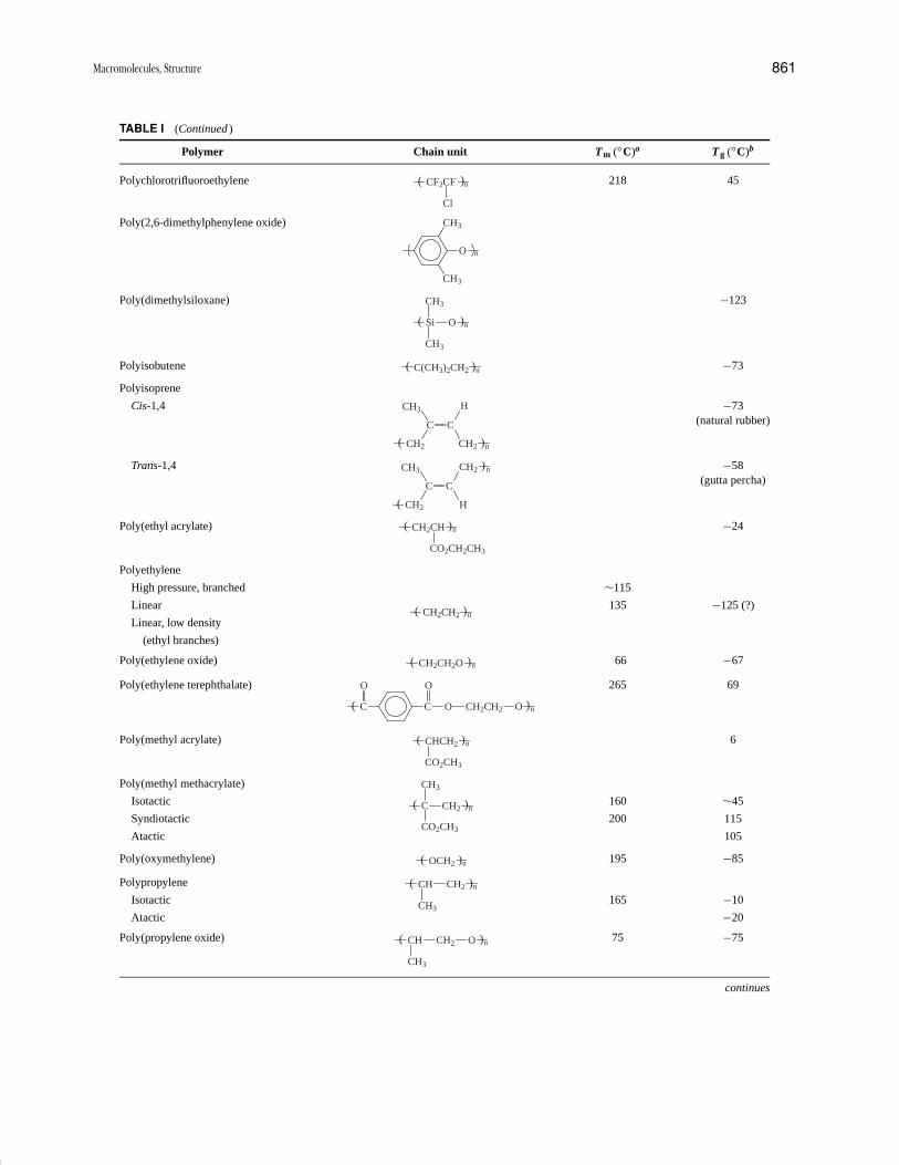
P1: GQT/LBX P2: GQT/MBQ QC: FYD Final Pages
Encyclopedia of Physical Science and Technology EN008C-602 July 25, 2001 20:31
Macromolecules, Structure 861
TABLE I (Continued )
Polymer Chain unit Tm (◦C)a Tg (◦C)b
Polychlorotrifluoroethylene 218 45CF n
Cl
CF2( (
Poly(2,6-dimethylphenylene oxide)
n
CH3
O
CH3
Poly(dimethylsiloxane) −123
n
CH3
OSi
CH3
( (
Polyisobutene −73nC(CH3)2CH2( (
Polyisoprene
Cis-1,4 −73(natural rubber)
n
C C
CH3
CH2
H
CH2( (
Trans-1,4 −58(gutta percha)C C
CH3
CH2
CH2
H
(
n
(
Poly(ethyl acrylate) −24CH2CH
(
n(
CO2CH2CH3
Polyethylene
High pressure, branched ∼115
Linear 135 −125 (?)
Linear, low density
(ethyl branches)
CH2CH2
(
n(
Poly(ethylene oxide) 66 −67( CH2CH2O
(
n
Poly(ethylene terephthalate) 265 69
( C
(
n
O
C O
O
CH2CH2 O
Poly(methyl acrylate) 6( CHCH2
(
n
CO2CH3
Poly(methyl methacrylate)
Isotactic 160 ∼45
Syndiotactic 200 115
Atactic 105
( C
(
n
CO2CH3
CH3
CH2
Poly(oxymethylene) 195 −85OCH2 n( (
Polypropylene
Isotactic 165 −10
Atactic −20
CH nCH2
CH3
( (
Poly(propylene oxide) 75 −75CH nCH2
CH3
O( (
continues
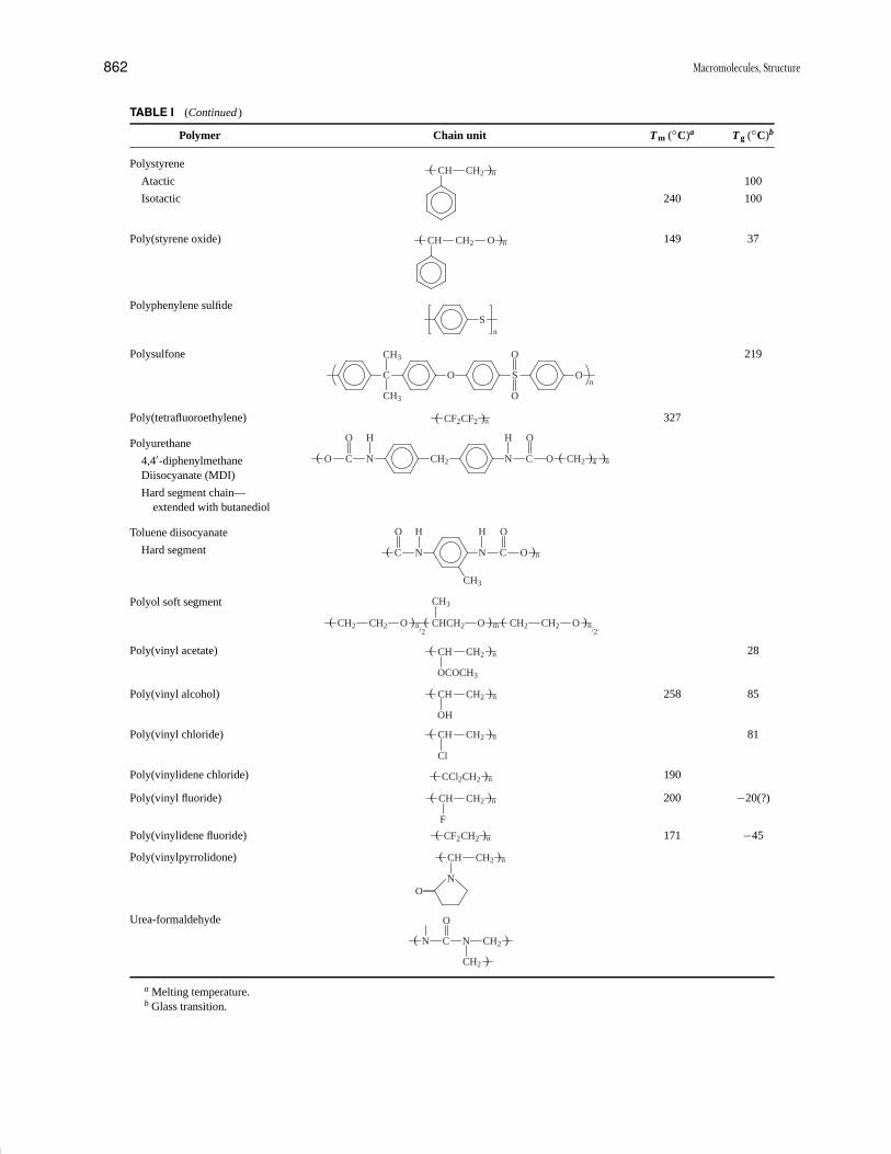
P1: GQT/LBX P2: GQT/MBQ QC: FYD Final Pages
Encyclopedia of Physical Science and Technology EN008C-602 July 25, 2001 20:31
862 Macromolecules, Structure
TABLE I (Continued )
Polymer Chain unit Tm (◦C)a Tg (◦C)b
Polystyrene
Atactic 100
Isotactic 240 100
CH nCH2( (
Poly(styrene oxide) 149 37CH nCH2 O( (
Polyphenylene sulfide
n
S
Polysulfone 219
C O S O
CH3
CH3
O
O
n
Poly(tetrafluoroethylene) 327CF2CF2 n( (
Polyurethane
4,4′-diphenylmethaneDiisocyanate (MDI)
Hard segment chain—extended with butanediol
O 4C N
O H
CH2 CN
OH
O CH2 n( ( ((
Toluene diisocyanate
Hard segment C nN
O H
CN
OH
O
CH3
( (Polyol soft segment
CH2 CH2 O n/2
CHCH2 O m CH2 CH2 O n/2
CH3
( ( ( ( ( (
Poly(vinyl acetate) 28CH CH2 n
OCOCH3
( (
Poly(vinyl alcohol) 258 85CH CH2 n
OH
( (
Poly(vinyl chloride) 81CH CH2 n
Cl
( (
Poly(vinylidene chloride) 190CCl2CH2 n( (
Poly(vinyl fluoride) 200 −20(?)CH nCH2( (
F
Poly(vinylidene fluoride) 171 −45CF2 nCH2( (
Poly(vinylpyrrolidone) CH nCH2
NO
( (
Urea-formaldehyde
N C N CH2
O
CH2
( (
(
a Melting temperature.b Glass transition.

P1: GQT/LBX P2: GQT/MBQ QC: FYD Final Pages
Encyclopedia of Physical Science and Technology EN008C-602 July 25, 2001 20:31
Macromolecules, Structure 863
TABLE II Trade Names of Selected Polymers
ABS Acrylonitrile–butadiene–styrene graft copolymers
Acrylic Poly(acrylonitrile)
Amberlite Ion-exchange resins
Bakelite Phenol-formaldehyde
Buna N Butadiene–acrylonitrile copolymer
Buna S (SBR) Butadiene–styrene copolymer
Butyl rubber Poly(isobutylene) + ∼1% isoprene
Carbowax Poly(ethylene glycol)
Cellophane Cellulose hydrate
Celluloid Cellulose nitrate
Cycolac ABS
Dacron Poly(ethylene terephthalate) fiber
Delrin Poly(oxymethylene)
Dynel Vinyl chloride–acrylonitrile copolymer
Epon Epoxy resin
Estane Polyurethane
HIPS High-impact polystyrene—copolymer of styreneand butadiene
Hytrel Poly(butylene terephthalate)–poly(butylene glycol)copolymer
Kapton Polyimide
Kel-F Poly(chlorotrifluoroethylene)
Kevlar Polyaramide fiber
Lexan Polycarbonate
Lucite Poly(methyl methacrylate)
Marlex Polyethylene
Mylar Polyester film
Neoprene Poly(chloroprene)
Orlon Poly(acrylonitrile)
Plexiglas Poly(methyl methacrylate)
PPO Poly(2,6-dimethyl phenylene oxide)
PVC Poly(vinyl chloride)
Rayon Fibers from regenerated cellulose
Ryton Polyphenylene sulfide
SBR (See Buna S)
Silicone Dialkyl siloxanes
Spandex Fibers from elastic polyurethanes
Styrofoam Polystyrene
Teflon Poly(tetrafluoroethylene)
Viton Vinylidene fluoride–hexafluoropropylene copolymer
composed of two or more monomer units and can occurin random, alternating, block or graft copolymers.
Figure 2 schematically illustrates the next level ofdetail—the chemical structure of the monomer unit. Thepolymer in this drawing is polyethylene, composed mainlyof repeating (CH2 ) units. The main chain and a butylbranch are shown under the magnifying glass. (Butylbranches occur at the level of approximately 1 per 100 CH2
groups.)
FIGURE 2 Examination of the chemical details in branchedpolyethylene. Within the magnifying glass, the large balls repre-sent carbon atoms and the small ones are the hydrogen atoms.The four-carbon segment is a butyl branch.
C. Formation of Macromolecules
As an introduction to the understanding of structure,we must first consider the formation of macromolecules.Polymer formation involves either chain or step reactions,or living polymerization. Earlier, the terms addition andcondensation, respectively, were used to describe chainand step growth polymerization. One important differencebetween the mechanisms is shown in Fig. 3, which showsa plot of the polymer molecular weight versus monomerconsumption. In step polymerization, once the chain is ini-tiated monomer molecules add in rapid succession to thereactive end group of the growing polymer chain until itterminates and becomes unreactive. In the growth or prop-agation step, several thousand monomer units add one ata time to each growing chain in a time interval of less than1 sec. Thus, at any stage of a chain polymerization, the re-acting system in effect consists of two species: monomersand very large molecular weight polymers. The forma-tion of polystyrene from styrene is an example of chainpolymerization.
FIGURE 3 The dependence of molecular weight on monomerconversion for (A) chain polymerization, (B) step polymerization,and (C) living polymerization.

P1: GQT/LBX P2: GQT/MBQ QC: FYD Final Pages
Encyclopedia of Physical Science and Technology EN008C-602 July 25, 2001 20:31
864 Macromolecules, Structure
In step reactions, for example, in the reaction of adipicacid and hexamethylenediamine,
HO
O
O
OH�
H2NNH2
HO
O
ONH2
HN
the growing molecules remain reactive and continue togrow by condensation through out the reaction period,which may be several hours. Although the “monomers”remain, their proportion on a weight basis rapidly becomesnegligible (although on a molar basis they remain the mostprobable species).
In living polymerization, the chains continue to growwithout chain transfer or termination. During the transfer-less polymerization, the number of polymer molecules re-mains constant. There is no termination, so the chain endsremain active when all of the monomer has been polymer-ized, and when fresh monomer is added, polymerizationresumes. Because the chains are all growing at the samerate, they are more uniform than those prepared by othermethods. This makes living polymerizations an invaluablemethod for preparing block, graft, and star copolymers.
The polymer properties are often dependent both onthe chain length (molecular weight) and the distributionin chain lengths. In chain reactions there is a large distri-bution in molecular weights because of the random natureof the initiation and termination processes. In step reac-tions, it results from random interactions of all species,the rates of which are independent of molecular weight.By comparison, the chains from the living polymerizationare more uniform in molecular weight. The methods formeasuring molecular weight distributions and averagesare discussed in Section II.
D. Isomerism in Macromolecular Chains
In polymers produced by step reactions there is generallyno formation of isomeric species in the usual sense exceptfor those that may be readily predicted from the knowncomposition of the starting mixture. Thus, for example,in the reaction of ethylene glycol and succinic acid toproduce the polyester poly(ethylene succinate),
HOOC(CH2)2COOCH2CH2OCO(CH2)2CO
· · · OCH2CH2OH
the introduction of a measured quantity of glycerol willproduce a predictable proportion and distribution of tri-functional branch units:
O
CO
(CH2)2
CO
O
OCO(CH2)2CO2CH2CHCH2OCO(CH2)2CO
This predictability stems from the fact that the reactionsinvolved are straightforward and well understood.
On the other hand, in the chain propagation reaction invinyl monomer polymerization, many options are possibleand their occurrence and structure are not so readily pre-dictable. Hence, such isomeric species must be determinedby spectroscopic or other means. One such option is theformation of inverted or head-to-head:tail-to-tail units, aswe have seen. Actually, in polystyrene formed by the usualchain reactions of styrene, the occurrence of such units isnegligible, but in the polymerization of such monomersas vinylidene fluoride and vinyl fluoride they occur witha substantial probability (see Section III).
Vinyl polymers may also exhibit marked differencesin stereochemical configuration (i.e., the relative handed-ness of successive monomer units may vary). The simplestregular arrangements of successive units are the isotacticstructure (Fig. 4a), in which all R substituents are locatedon the same side of the zigzag plane, representing the chainstretched out in an all-trans (see Section IV) conforma-tion, and the syndiotactic arrangement, in which R groupsalternate regularly from side to side (Fig. 4b). In the atac-tic arrangement, the R groups appear at random on eitherside of the zigzag plane (Fig. 4c). These isomeric formsare determined by the covalent bonding of each monomerunit and cannot be interconverted by rotations about themain chain bonds.
Another type of isomerism occurs in polymers havingunsaturation in the main chain. Since carbon atoms linkedtogether by double bonds are not free to rotate about thechain axis, repeating units in polymers such as polyiso-prene can exist as two different geometrical isomers:
C
CH3
CH2
C
H
CH2
C
CH3
CH2
C
CH2
H
cis trans
NATURAL RUBBER GUTTA PERCHA
The trans polymer is a semicrystalline plastic whereas thecis form is normally a rubber at room temperature.
Yet another option is the production of branching, bothshort and long. An example of branching in polyethylene
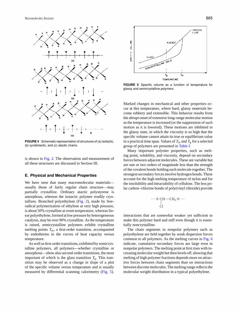
P1: GQT/LBX P2: GQT/MBQ QC: FYD Final Pages
Encyclopedia of Physical Science and Technology EN008C-602 July 25, 2001 20:31
Macromolecules, Structure 865
FIGURE 4 Schematic representation of structures of (a) isotactic,(b) syndiotactic, and (c) atactic chains.
is shown in Fig. 2. The observation and measurement ofall these structures are discussed in Section III.
E. Physical and Mechanical Properties
We have seen that many macromolecular materials—usually those of fairly regular chain structure—maypartially crystallize. Ordinary atactic polystyrene isamorphous, whereas the isotactic polymer readily crys-tallizes. Branched polyethylene (Fig. 2), made by free-radical polymerization of ethylene at very high pressure,is about 50% crystalline at room temperature, whereas lin-ear polyethylene, formed at low pressure by heterogeneouscatalysis, may be over 90% crystalline. As the temperatureis raised, semicrystalline polymers exhibit crystallinemelting points Tm, a first-order transition, accompaniedby endotherms in the curves of heat capacity versustemperature.
As well as first-order transitions, exhibited by semicrys-talline polymers, all polymers—whether crystalline oramorphous—show also second-order transitions, the mostimportant of which is the glass transition Tg. This tran-sition may be observed as a change in slope of a plotof the specific volume versus temperature and is usuallymeasured by differential scanning calorimetry (Fig. 5).
FIGURE 5 Specific volume as a function of temperature forglassy and semicrystalline polymers.
Marked changes in mechanical and other properties oc-cur at this temperature, where hard, glassy materials be-come rubbery and extensible. This behavior results fromthe abrupt onset of extensive long-range molecular motionas the temperature is increased (or the suppression of suchmotion as it is lowered). These motions are inhibited inthe glassy state, in which the viscosity is so high that thespecific volume cannot attain its true or equilibrium valuein a practical time span. Values of Tm and Tg for a selectedgroup of polymers are presented in Table I.
Many important polymer properties, such as melt-ing point, solubility, and viscosity, depend on secondaryforces between adjacent molecules. These are variable butare one or two orders of magnitude less than the strengthof the covalent bonds holding each molecule together. Thestrongest secondary forces involve hydrogen bonds. Theseaccount for the high melting temperature of nylon and forthe insolubility and intractability of cellulose. The less po-lar carbon–chlorine bonds of poly(vinyl chloride) provide
CH
Cl
CH2( (
interactions that are somewhat weaker yet sufficient tomake this polymer hard and stiff even though it is essen-tially noncrystalline.
The chain segments in nonpolar polymers such aspolyethylene are held together by weak dispersion forcescommon to all polymers. As the melting curves in Fig. 6indicate, cumulative secondary forces are large even innonpolar polymers. The melting point at first rises with in-creasing molecular weight but then levels off, showing thatmelting of high polymer fractions depends more on attrac-tive forces between chain segments than on interactionsbetween discrete molecules. The melting range reflects themolecular weight distribution in a typical polyethylene.
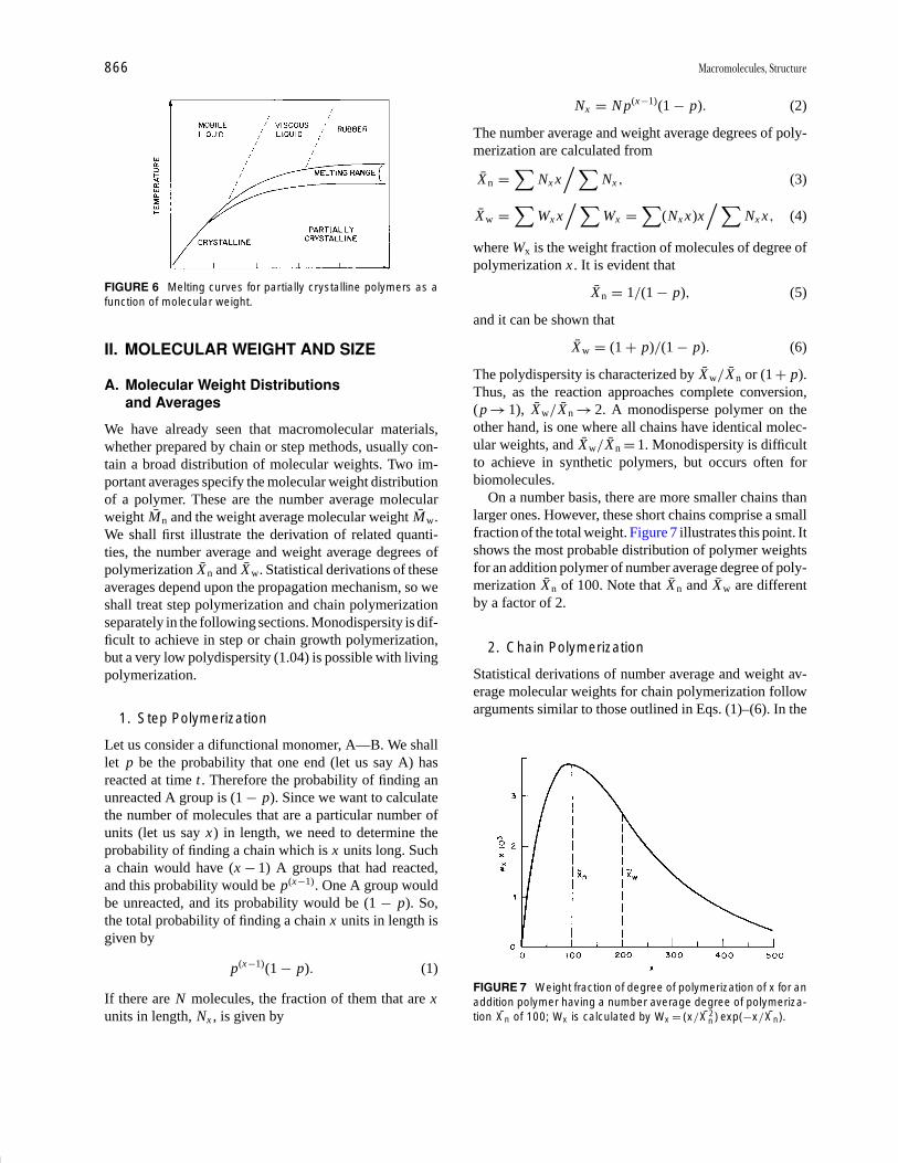
P1: GQT/LBX P2: GQT/MBQ QC: FYD Final Pages
Encyclopedia of Physical Science and Technology EN008C-602 July 25, 2001 20:31
866 Macromolecules, Structure
FIGURE 6 Melting curves for partially crystalline polymers as afunction of molecular weight.
II. MOLECULAR WEIGHT AND SIZE
A. Molecular Weight Distributionsand Averages
We have already seen that macromolecular materials,whether prepared by chain or step methods, usually con-tain a broad distribution of molecular weights. Two im-portant averages specify the molecular weight distributionof a polymer. These are the number average molecularweight Mn and the weight average molecular weight Mw.We shall first illustrate the derivation of related quanti-ties, the number average and weight average degrees ofpolymerization Xn and Xw. Statistical derivations of theseaverages depend upon the propagation mechanism, so weshall treat step polymerization and chain polymerizationseparately in the following sections. Monodispersity is dif-ficult to achieve in step or chain growth polymerization,but a very low polydispersity (1.04) is possible with livingpolymerization.
1. Step Polymerization
Let us consider a difunctional monomer, A—B. We shalllet p be the probability that one end (let us say A) hasreacted at time t . Therefore the probability of finding anunreacted A group is (1 − p). Since we want to calculatethe number of molecules that are a particular number ofunits (let us say x) in length, we need to determine theprobability of finding a chain which is x units long. Sucha chain would have (x − 1) A groups that had reacted,and this probability would be p(x −1). One A group wouldbe unreacted, and its probability would be (1 − p). So,the total probability of finding a chain x units in length isgiven by
p(x −1)(1 − p). (1)
If there are N molecules, the fraction of them that are xunits in length, Nx , is given by
Nx = N p(x −1)(1 − p). (2)
The number average and weight average degrees of poly-merization are calculated from
Xn =∑
Nx x/ ∑
Nx , (3)
Xw =∑
Wx x/ ∑
Wx =∑
(Nx x)x/ ∑
Nx x , (4)
where Wx is the weight fraction of molecules of degree ofpolymerization x . It is evident that
Xn = 1/(1 − p), (5)
and it can be shown that
Xw = (1 + p)/(1 − p). (6)
The polydispersity is characterized by Xw / Xn or (1 + p).Thus, as the reaction approaches complete conversion,(p → 1), Xw/Xn → 2. A monodisperse polymer on theother hand, is one where all chains have identical molec-ular weights, and Xw/Xn = 1. Monodispersity is difficultto achieve in synthetic polymers, but occurs often forbiomolecules.
On a number basis, there are more smaller chains thanlarger ones. However, these short chains comprise a smallfraction of the total weight. Figure 7 illustrates this point. Itshows the most probable distribution of polymer weightsfor an addition polymer of number average degree of poly-merization Xn of 100. Note that Xn and Xw are differentby a factor of 2.
2. Chain Polymerization
Statistical derivations of number average and weight av-erage molecular weights for chain polymerization followarguments similar to those outlined in Eqs. (1)–(6). In the
FIGURE 7 Weight fraction of degree of polymerization of x for anaddition polymer having a number average degree of polymeriza-tion Xn of 100; Wx is calculated by Wx = (x/X2
n ) exp(−x/Xn).
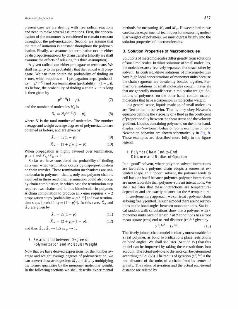
P1: GQT/LBX P2: GQT/MBQ QC: FYD Final Pages
Encyclopedia of Physical Science and Technology EN008C-602 July 25, 2001 20:31
Macromolecules, Structure 867
present case we are dealing with free radical reactionsand need to make several assumptions. First, the concen-tration of the monomer is considered to remain constantthroughout the polymerization. Second, we assume thatthe rate of initiation is constant throughout the polymer-ization. Finally, we assume that termination occurs eitherby disproportionation or by chain transfer (shortly we shallexamine the effects of relaxing this third assumption).
A given radical can either propagate or terminate. Weshall assign p to the probability that the radical will prop-agate. We can then obtain the probability of finding anx-mer, which requires x − 1 propagation steps [probabil-ity = p(x −1)] and one termination [probability = (1 − p)].As before, the probability of finding a chain x units longis then given by
p(x −1)(1 − p), (7)
and the number of molecules Nx is
Nx = N p(x −1)(1 − p), (8)
where N is the total number of molecules. The numberaverage and weight average degrees of polymerization areobtained as before, and are given by
Xn = 1/(1 − p), (9)
Xw = (1 + p)/(1 − p). (10)
When propagation is highly favored over termination,p → 1 and Xw / Xn → 2.
So far we have considered the probability of findingan x-mer when termination occurs by disproportionationor chain transfer. These termination mechanisms are uni-molecular in polymer—that is, only one polymer chain isinvolved in these reactions. Termination could also occurby chain combination, in which case the termination steprequires two chains and is thus bimolecular in polymer.A chain combination to produce an x-mer requires x − 2propagation steps [probability = p(x −2)] and two termina-tion steps [probability = (1 − p)2]. In this case, Xn andXw are given by
Xn = 2/(1 − p), (11)
Xw = (2 + p)/(1 − p), (12)
and thus Xw / Xn → 1.5 as p → 1.
3. Relationship between Degree ofPolymerization and Molecular Weight
Now that we have derived expressions for the number av-erage and weight average degrees of polymerization, wecan convert these averages into Mn and Mw by multiplyingthe former quantities by the monomer molecular weight.In the following sections we shall describe experimental
methods for measuring Mn and Mw. However, before wecan discuss experimental techniques for measuring molec-ular weights of polymers, we must digress briefly into thesolution properties of macromolecules.
B. Solution Properties of Macromolecules
Solutions of macromolecules differ greatly from solutionsof small molecules. In dilute solutions of small molecules,the molecules are effectively separated from each other bysolvent. In contrast, dilute solutions of macromoleculeshave high local concentrations of monomer units becausethe chain segments are covalently bonded together. Fur-thermore, solutions of small molecules contain materialsthat are generally monodisperse in molecular weight. So-lutions of polymers, on the other hand, contain macro-molecules that have a dispersion in molecular weight.
In a general sense, liquids made up of small moleculesare Newtonian in behavior. That is, they obey Newton’sequation defining the viscosity of a fluid as the coefficientof proportionality between the shear stress and the velocitygradient. Liquids containing polymers, on the other hand,display non-Newtonian behavior. Some examples of non-Newtonian behavior are shown schematically in Fig. 8.These examples are described more fully in the figurelegend.
1. Polymer Chain End-to-EndDistance and Radius of Gyration
In a “good” solvent, where polymer–solvent interactionsare favorable, a polymer chain adopts a somewhat ex-tended shape. In a “poor” solvent, the polymer tends tocoil back on itself because polymer–polymer interactionsare more favorable than polymer–solvent interactions. Weshall see later that these interactions are temperature-dependent and are exactly balanced at the θ temperature.
In an elementary approach, we can treat a polymer chainas being freely jointed. In such a model there are no restric-tions on the bond angles between monomer units. Statisti-cal random walk calculations show that a polymer with xmonomer units each of length I at θ conditions has a rootmean square (rms) end-to-end distance 〈r2〉1/2 given by
〈r2〉1/2 = lx1/2. (13)
This freely jointed chain model is clearly unreasonable fora real polymer, as bond hybridizations place restrictionson bond angles. We shall see later (Section IV) that thismodel can be improved by taking these restrictions intoaccount. The actual end-to-end distance can be determinedaccording to Eq. (68). The radius of gyration 〈s2〉1/2 is therms distance of the units of a chain from its center ofgravity. The radius of gyration and the actual end-to-enddistance are related by
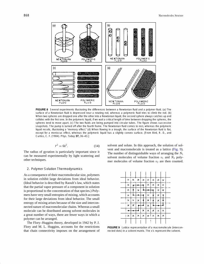
P1: GQT/LBX P2: GQT/MBQ QC: FYD Final Pages
Encyclopedia of Physical Science and Technology EN008C-602 July 25, 2001 20:31
868 Macromolecules, Structure
FIGURE 8 Several experiments illustrating the differences between a Newtonian fluid and a polymer fluid. (a) Thesurface of a Newtonian fluid is depressed near a rotating rod, whereas a polymeric fluid tries to climb the rod. (b)When two spheres are dropped one after the other into a Newtonian liquid, the second sphere always catches up andcollides with the first one. In the polymeric liquid, if we wait a critical length of time between dropping the spheres, thespheres tend to move apart. (c) The two fluids are being pumped into circular tubes. The figure shows successivesnapshots. The pump is turned off after the fourth frame. The Newtonian fluid comes to rest, whereas the polymericliquid recoils, illustrating a “memory effect.” (d) When flowing in a trough, the surface of the Newtonian fluid is flat,except for a meniscus effect, whereas the polymeric liquid has a slightly convex surface. [From Bird, R. D., andCurtiss, C. F. (1984). Phys. Today 37, 36–43.]
r2 = 6s2 . (14)
The radius of gyration is particularly important since itcan be measured experimentally by light scattering andother techniques.
2. Polymer Solution Thermodynamics
As a consequence of their macromolecular size, polymersin solution exhibit large deviations from ideal behavior.(Ideal behavior is described by Raoult’s law, which statesthat the partial vapor pressure of a component in solutionis proportional to the concentration of that species.) Poly-mers have very small entropies of mixing, which accountsfor their large deviations from ideal behavior. The smallentropy of mixing arises because of the size and intercon-nected nature of macromolecular chains. Whereas a smallmolecule can be distributed among solvent molecules ina great number of ways, there are fewer ways in which apolymer can be arranged.
The Flory–Huggins theory, developed in 1942 by P. J.Flory and M. L. Huggins, accounts for the restrictionsthat chain connectivity imposes on the arrangement of
solvent and solute. In this approach, the solution of sol-vent and macromolecule is treated as a lattice (Fig. 9).The number of distinguishable ways of arranging the N1
solvent molecules of volume fraction v1 and N2 poly-mer molecules of volume fraction v2 are then counted.
FIGURE 9 Lattice representation of a macromolecule (intercon-nected dots) in a solvent matrix. The x’s represent the solvent.
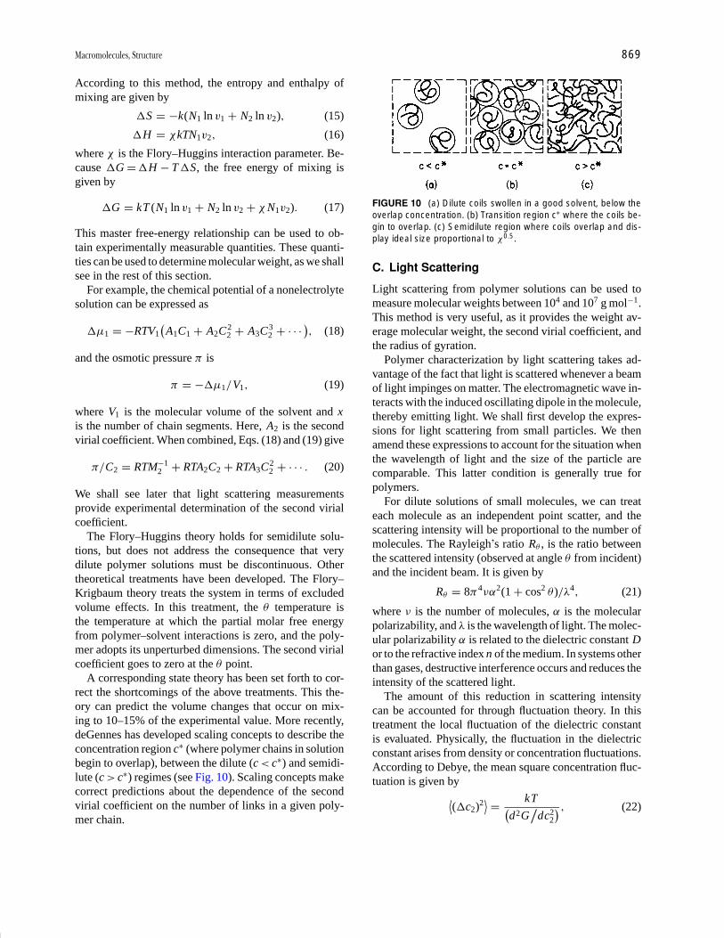
P1: GQT/LBX P2: GQT/MBQ QC: FYD Final Pages
Encyclopedia of Physical Science and Technology EN008C-602 July 25, 2001 20:31
Macromolecules, Structure 869
According to this method, the entropy and enthalpy ofmixing are given by
�S = −k(N1 ln v1 + N2 ln v2), (15)
�H = χkTN1 v2 , (16)
where χ is the Flory–Huggins interaction parameter. Be-cause �G = �H − T �S, the free energy of mixing isgiven by
�G = kT (N1 ln v1 + N2 ln v2 + χ N1 v2). (17)
This master free-energy relationship can be used to ob-tain experimentally measurable quantities. These quanti-ties can be used to determine molecular weight, as we shallsee in the rest of this section.
For example, the chemical potential of a nonelectrolytesolution can be expressed as
�µ1 = −RTV1(
A1C1 + A2C22 + A3C3
2 + · · · ), (18)
and the osmotic pressure π is
π = −�µ1 /V1 , (19)
where V1 is the molecular volume of the solvent and xis the number of chain segments. Here, A2 is the secondvirial coefficient. When combined, Eqs. (18) and (19) give
π/C2 = RTM−12 + RTA2C2 + RTA3C2
2 + · · · . (20)
We shall see later that light scattering measurementsprovide experimental determination of the second virialcoefficient.
The Flory–Huggins theory holds for semidilute solu-tions, but does not address the consequence that verydilute polymer solutions must be discontinuous. Othertheoretical treatments have been developed. The Flory–Krigbaum theory treats the system in terms of excludedvolume effects. In this treatment, the θ temperature isthe temperature at which the partial molar free energyfrom polymer–solvent interactions is zero, and the poly-mer adopts its unperturbed dimensions. The second virialcoefficient goes to zero at the θ point.
A corresponding state theory has been set forth to cor-rect the shortcomings of the above treatments. This the-ory can predict the volume changes that occur on mix-ing to 10–15% of the experimental value. More recently,deGennes has developed scaling concepts to describe theconcentration region c∗ (where polymer chains in solutionbegin to overlap), between the dilute (c < c∗) and semidi-lute (c > c ∗) regimes (see Fig. 10). Scaling concepts makecorrect predictions about the dependence of the secondvirial coefficient on the number of links in a given poly-mer chain.
FIGURE 10 (a) Dilute coils swollen in a good solvent, below theoverlap concentration. (b) Transition region c∗ where the coils be-gin to overlap. (c) Semidilute region where coils overlap and dis-play ideal size proportional to χ0.5.
C. Light Scattering
Light scattering from polymer solutions can be used tomeasure molecular weights between 104 and 107 g mol−1.This method is very useful, as it provides the weight av-erage molecular weight, the second virial coefficient, andthe radius of gyration.
Polymer characterization by light scattering takes ad-vantage of the fact that light is scattered whenever a beamof light impinges on matter. The electromagnetic wave in-teracts with the induced oscillating dipole in the molecule,thereby emitting light. We shall first develop the expres-sions for light scattering from small particles. We thenamend these expressions to account for the situation whenthe wavelength of light and the size of the particle arecomparable. This latter condition is generally true forpolymers.
For dilute solutions of small molecules, we can treateach molecule as an independent point scatter, and thescattering intensity will be proportional to the number ofmolecules. The Rayleigh’s ratio Rθ , is the ratio betweenthe scattered intensity (observed at angle θ from incident)and the incident beam. It is given by
Rθ = 8π4να2(1 + cos2 θ )/λ4, (21)
where ν is the number of molecules, α is the molecularpolarizability, and λ is the wavelength of light. The molec-ular polarizability α is related to the dielectric constant Dor to the refractive index n of the medium. In systems otherthan gases, destructive interference occurs and reduces theintensity of the scattered light.
The amount of this reduction in scattering intensitycan be accounted for through fluctuation theory. In thistreatment the local fluctuation of the dielectric constantis evaluated. Physically, the fluctuation in the dielectricconstant arises from density or concentration fluctuations.According to Debye, the mean square concentration fluc-tuation is given by
⟨(�c2)2
⟩ = kT(d2G
/dc2
2
) , (22)

P1: GQT/LBX P2: GQT/MBQ QC: FYD Final Pages
Encyclopedia of Physical Science and Technology EN008C-602 July 25, 2001 20:31
870 Macromolecules, Structure
where G is the free energy. A fluctuation in concentrationis related to the osmotic pressure [recall from Eq. (19) thatthe osmotic pressure has the form dG/dc2]. Equation (22)shows that a higher-than-equilibrium concentration fluc-tuation will be opposed by the osmotic pressure.
If we let �Rθ be the change in light scattering causedby concentration fluctuations, we can show that �Rθ isrelated to osmotic pressure π by
�Rθ = KTRc2
(d π/dc2) , (23)
where
K = 2π2n2(dn/dc2)2
νλ4 . (24)
Proper evaluation of (d π/dc2) yields
K c2 /�R θ = 1/M + 2A2c2 + 3A3c22 + · · · , (25)
where M is the solute molecular weight and A2 is the sec-ond virial coefficient, as before. Equation (25) shows that aplot of K c2 /�R θ versus c2 will give an intercept of 1/M atc2 = 0. Except in rare cases, polymers have a distributionin molecular weight. We can see the relationship betweenlight scattering and weight average molecular weight Mw
by adding in the contributions from all species ci withmolecular weights Mi . In the limit of
c2 → 0, �Rθ =∑
i
(�Rθ )i = K∑
i
ci Mi ,
limc2 →0
K c2
�Rθ
=∑
i ci∑i ci Mi
= 1
Mw. (26)
We must now modify this expression to account for thegenerally encountered situation where the polymer dimen-sions are comparable to ∼1/20 the wavelength of light.The particle can no longer be treated as a point scatterer be-cause destructive interference occurs from light scatteredby different parts of the particle itself. The destructive in-terference is largest at large angles θ between the incidentand measured light, and it disappears as θ approaches zero.A correction factor, P(θ ), is obtained by averaging overall possible angular relationships between the scatteringpoints and the incident beam. The modified expression forK c2 /�R θ becomes(
K c2
�Rθ
)c2 →0
= 1
Mw P(θ )
= 1
Mw
(1 + 16π2
3λ2 〈s2 〉 sin2 θ
2+ · · ·
).
(27)
The weight average molecular weight, Mw, is obtainedby measuring K c2 /�R θ at a number of concentrations
FIGURE 11 Zimm plot of light scattering data for polystyrene inbutanone. [From Zimm, B. H. (1948). J. Chem. Phys. 16, 1099.]
and as a function of scattering angle θ . A Zimm plot (seeFig. 11) is then constructed from the data. K c2 /�R θ isplotted against sin2(θ/2). The points corresponding to thec2 = 0 data and the θ = 0 data are shown in Fig. 11 asfilled circles. Lines through these points should intersectthe ordinate at the same place, equal to 1/ Mw. The secondvirial coefficient is obtained from the slope of the θ = 0line and the radius of gyration comes from the slope of thec2 = 0 line.
D. Size Exclusion Chromatography
Size exclusion chromatography, also called gel per-meation chromatography (GPC) is a widely employedmethod to determine molecular size. In this method, achromatographic column is packed with porous beads.The beads are made either of glass or of polymeric mate-rial such as highly cross-linked polystyrene. They are pre-pared to have pore sizes that correspond approximately tothe size of polymer molecules. The beads are equilibratedwith the appropriate elution solvent before measurementis begun.
A solution of the polymer is introduced on the top of thecolumn. Solvent is added to the top of the column to matchthe flux of solvent from the bottom of the column (Fig. 12).A detector, positioned immediately after the solvent haspassed through the column, keeps track of the amount ofsolvent that has eluted (this amount is called the retentionvolume) as well as the amount of polymer in that volume.(The amount of polymer is detected by a number of meth-ods, including ultraviolet spectroscopy or refractive indexmeasurements.)
We can visualize how the column technique works byconsidering two extreme cases—a very small polymer

P1: GQT/LBX P2: GQT/MBQ QC: FYD Final Pages
Encyclopedia of Physical Science and Technology EN008C-602 July 25, 2001 20:31
Macromolecules, Structure 871
FIGURE 12 Schematic representation of a chromatographic col-umn and typical data output (the chromatogram) from the detector.Large molecules elute first, at early retention volumes.
molecule and a very large one. When loaded onto the col-umn, the small molecule begins its descent through thebeads. Owing to its small size, it diffuses into the pores ofthe beads and is entrained in the internal structures of thebeads during its journey to the bottom of the column. Thevery small molecule will spend much time on the columnand will therefore have a large retention volume. The verylarge molecule, on the other hand, will be excluded, ormostly excluded, from the pores of the beads. Its journeyto the bottom of the column will be relatively rapid, andit will appear in the early elution volumes.
So far we have shown that the molecules are eluted inorder of decreasing molecular size. Calibrations are re-quired to relate the retention volume to molecular weight.These calibrations are usually performed with commer-cially available polystyrenes of narrow molecular weightdistributions. The position of the chromatogram peak thusgives Mw indirectly through calibration curves. The widthof the peak on the chromatogram is related to the molec-ular weight distribution Mw / Mn.
E. Ultracentrifugation
Ultracentrifugation methods are used primarily for the de-termination of biopolymer molecular weights. A solutionof the polymer is placed in a centrifuge cell. (The solventhas been carefully selected for its density and refractiveindex differences from the polymer.) The centrifuge cellis placed in a rotor. The cell and rotor are constructed toallow refractive index measurements along the length ofthe cell. Centrifugation is then performed under vacuumat high speed and at controlled temperatures. There areseveral variations of the centrifugation experiment.
The sedimentation equilibrium experiment consists ofcentrifuging the sample at low speeds for long periods oftime. At equilibrium the polymer is distributed accordingto its molecular weight. At this point the centripetal forceis exactly balanced by the back diffusion of the polymer
along the concentration gradient in the cell. In mathemat-ical terms, this means that force on a particle of mass m,which is a distance r from the center of the rotor rotatingat angular velocity ω, is given by
F = ω2r (1 − vρ)m , (28)
where ρ is the density of the solution and v is the partialspecific volume of the polymer. For ideal solutions it canbe shown from this expression that
Mw = 2RT ln (c2 /c1)
(1 − vρ)ω2 (r2
2 − r21
) , (29)
where c1 and c2 are the concentrations at points r1 and r2
in the cell.A variation of this experiment is sedimentation equi-
librium in a density gradient. A centrifuge cell containinga known density gradient is prepared. (Sucrose densitygradients are often used for biological polymers.) Uponcentrifugation, the polymer distributes itself in the bandwith the density that exactly matches its own.
High speed centrifugation is used in the sedimentationtransport experiment. The sedimentation constant, sc, de-scribes the rate at which the polymer moves to the bottomof the cell:
sc = 1
ω2r
dr
dt= m(1 − vρ)
f, (30)
where f is the frictional coefficient. The frictional coef-ficient for a random coil polymer is not the simple onecalculated for a hard sphere by Stokes’ law but rather canbe related to the diffusion coefficient D. At infinite dilu-tion f is given by
f = kT/D, (31)
and sc becomes
sc = Dm(1 − vρ)/kT . (32)
The distribution in sc can be converted to a distribution inmolecular weight.
F. Viscosity Measurements
Solutions of polymers are viscous and viscosity mea-surements can be used to determine polymer molecularweights. Viscosity provides an indirect measure of molec-ular weight, since a calibration curve must be establishedfor viscosity measurements, as is also the case for GPCmeasurements. Experimental viscosity measurements areperformed in a capillary viscometer such as the one shownin Fig. 13(a). The viscosity experiment consists of firstmeasuring the time t0 that it takes for the solvent to passbetween the two etched lines on the viscometer. Then the
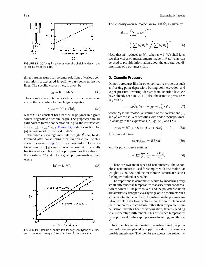
P1: GQT/LBX P2: GQT/MBQ QC: FYD Final Pages
Encyclopedia of Physical Science and Technology EN008C-602 July 25, 2001 20:31
872 Macromolecules, Structure
FIGURE 13 (a) A capillary viscometer of Ubbelohde design and(b) typical viscosity data.
times t are measured for polymer solutions of various con-centrations c, expressed in g/dL, to pass between the twolines. The specific viscosity ηsp is given by
ηsp = (t − t0)/t0 . (33)
The viscosity data obtained as a function of concentrationare plotted according to the Huggins equation
ηsp /c = [η] + k ′[η]2c , (34)
where k ′ is a constant for a particular polymer in a givensolvent regardless of chain length. The graphical data areextrapolated to zero concentration to give the intrinsic vis-cosity, [η] = (ηsp /c)c =0. Figure 13(b) shows such a plot;[η] is customarily expressed in dL/g.
The viscosity average molecular weight Mv can be de-termined after constructing a calibration curve. Such acurve is shown in Fig. 14. It is a double-log plot of in-trinsic viscosity [η] versus molecular weight of carefullyfractionated samples. Such a plot provides the values ofthe constants K ′ and α for a given polymer–solvent pair,where
[η] = K ′Mα. (35)
FIGURE 14 Intrinsic viscosity data for polyisobutylene as a func-tion of molecular weight. Data are shown for two solvents.
The viscosity average molecular weight Mv is given by
Mv =(∑
i
vi Mαi
)1/α
=( ∑
i
Ni M1+αi
/ ∑i
Ni Mi
)1/α
. (36)
Note that Mv reduces to Mw when α = 1. We shall latersee that viscosity measurements made in θ solvents canbe used to provide information about the unperturbed di-mensions of a polymer chain.
G. Osmotic Pressure
Osmotic pressure, like the other colligative properties suchas freezing point depression, boiling point elevation, andvapor pressure lowering, derives from Raoult’s law. Wehave already seen in Eq. (19) that the osmotic pressure π
is given by
π = �G1/V1 = −(µ1 − µ0
1
)/V1, (37)
where V1 is the molecular volume of the solvent and µ1
and µ01 are the solvent activities with and without polymer.
In analogy to the expansions in Eqs. (20) and (25),
π/c2 = RT[(1/M) + A2c2 + A3c2
2 + · · ·)]. (38)
At infinite dilution
(π/c2)c2=0 = RT/M, (39)
and for polydisperse systems,
π = RT∑
i
ci
Mi= RT c2
Mn. (40)
There are two main types of osmometers. The vapor-phase osmometer is used for samples with low molecularweights (<40,000) and the membrane osmometer is bestfor higher molecular weights.
The vapor-phase osmometer works by measuring verysmall differences in temperature that arise from condensa-tion of solvent. The pure solvent and the polymer solutionare alternately dropped via a syringe onto a thermistor in asolvent-saturated chamber. The solvent in the polymer so-lution droplet has a lower activity than the pure solvent andtherefore prefers to condense rather than evaporate. Con-densation liberates heat of vaporization, thereby leadingto a temperature differential. This difference temperatureis proportional to the vapor pressure lowering, and thus toMn.
In a membrane osmometer, the solvent and the poly-mer solution are placed on opposite sides of a semiper-meable membrane. The membrane allows the solvent to
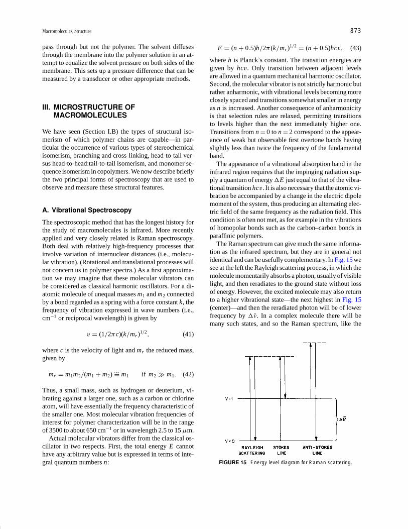
P1: GQT/LBX P2: GQT/MBQ QC: FYD Final Pages
Encyclopedia of Physical Science and Technology EN008C-602 July 25, 2001 20:31
Macromolecules, Structure 873
pass through but not the polymer. The solvent diffusesthrough the membrane into the polymer solution in an at-tempt to equalize the solvent pressure on both sides of themembrane. This sets up a pressure difference that can bemeasured by a transducer or other appropriate methods.
III. MICROSTRUCTURE OFMACROMOLECULES
We have seen (Section I.B) the types of structural iso-merism of which polymer chains are capable—in par-ticular the occurrence of various types of stereochemicalisomerism, branching and cross-linking, head-to-tail ver-sus head-to-head:tail-to-tail isomerism, and monomer se-quence isomerism in copolymers. We now describe brieflythe two principal forms of spectroscopy that are used toobserve and measure these structural features.
A. Vibrational Spectroscopy
The spectroscopic method that has the longest history forthe study of macromolecules is infrared. More recentlyapplied and very closely related is Raman spectroscopy.Both deal with relatively high-frequency processes thatinvolve variation of internuclear distances (i.e., molecu-lar vibration). (Rotational and translational processes willnot concern us in polymer spectra.) As a first approxima-tion we may imagine that these molecular vibrators canbe considered as classical harmonic oscillators. For a di-atomic molecule of unequal masses m1 and m2 connectedby a bond regarded as a spring with a force constant k, thefrequency of vibration expressed in wave numbers (i.e.,cm−1 or reciprocal wavelength) is given by
v = (1/2πc)(k /mr )1/2 , (41)
where c is the velocity of light and mr the reduced mass,given by
mr = m1m2 /(m1 + m2) ∼= m1 if m2 � m1 . (42)
Thus, a small mass, such as hydrogen or deuterium, vi-brating against a larger one, such as a carbon or chlorineatom, will have essentially the frequency characteristic ofthe smaller one. Most molecular vibration frequencies ofinterest for polymer characterization will be in the rangeof 3500 to about 650 cm−1 or in wavelength 2.5 to 15 µm.
Actual molecular vibrators differ from the classical os-cillator in two respects. First, the total energy E cannothave any arbitrary value but is expressed in terms of inte-gral quantum numbers n:
E = (n + 0.5)h /2π (k /mr )1/2 = (n + 0.5)hcv, (43)
where h is Planck’s constant. The transition energies aregiven by hcv. Only transition between adjacent levelsare allowed in a quantum mechanical harmonic oscillator.Second, the molecular vibrator is not strictly harmonic butrather anharmonic, with vibrational levels becoming moreclosely spaced and transitions somewhat smaller in energyas n is increased. Another consequence of anharmonicityis that selection rules are relaxed, permitting transitionsto levels higher than the next immediately higher one.Transitions from n = 0 to n = 2 correspond to the appear-ance of weak but observable first overtone bands havingslightly less than twice the frequency of the fundamentalband.
The appearance of a vibrational absorption band in theinfrared region requires that the impinging radiation sup-ply a quantum of energy �E just equal to that of the vibra-tional transition hcv. It is also necessary that the atomic vi-bration be accompanied by a change in the electric dipolemoment of the system, thus producing an alternating elec-tric field of the same frequency as the radiation field. Thiscondition is often not met, as for example in the vibrationsof homopolar bonds such as the carbon–carbon bonds inparaffinic polymers.
The Raman spectrum can give much the same informa-tion as the infrared spectrum, but they are in general notidentical and can be usefully complementary. In Fig. 15 wesee at the left the Rayleigh scattering process, in which themolecule momentarily absorbs a photon, usually of visiblelight, and then reradiates to the ground state without lossof energy. However, the excited molecule may also returnto a higher vibrational state—the next highest in Fig. 15(center)—and then the reradiated photon will be of lowerfrequency by �ν. In a complex molecule there will bemany such states, and so the Raman spectrum, like the
FIGURE 15 Energy level diagram for Raman scattering.

P1: GQT/LBX P2: GQT/MBQ QC: FYD Final Pages
Encyclopedia of Physical Science and Technology EN008C-602 July 25, 2001 20:31
874 Macromolecules, Structure
infrared spectrum, will appear as a number of lines, calledthe Stokes lines, much weaker than the exciting radiationand shifted to longer wavelength by a few hundred to twoor three thousand wave numbers. (Antistokes lines cor-responding to excitation from a higher vibrational stateare also observed but are much weaker and not normallyemployed.)
For Raman emission to occur, the polarizability of thebond must change during the vibration. In polymers, mostlines appear in both infrared and Raman spectra, an impor-tant exception being paraffinic carbon–carbon vibrations,which are inactive in the infrared (vide supra) but activein the Raman spectrum.
In polymers, as in small molecules, we may recognizevibrational bands specific to particular types of bonds andfunctional groups. These appear in the high-frequencyregion of the spectrum regardless of the actual compoundor structure in which they occur. At the low-frequencyend of the spectrum, the vibrational bands are more char-acteristic of the molecule as a whole. This region is com-monly called the “fingerprint” region, since detailed com-parison here usually enables specific identification to bemade.
In the region near 3000 cm−1 appear the C H bondstretching vibrations (Fig. 16), which may be asymmet-ric or symmetric, as illustrated in Fig. 17. These occurin nearly all polymer spectra and so are not structurallydiagnostic, although useful in a more fundamental sense.At lower frequencies, corresponding to smaller force con-stants, are the deformation vibrations involving valenceangle bending or scissoring, giving a large band near1500 cm−1; wagging and twisting near 1300 cm−1; and
FIGURE 16 Infrared bands of interest in polymers.
FIGURE 17 Stretching and deformation vibrational modes ofthe methylene group; (a) asymmetric stretching, 2926 cm−1
(3.42 µm); (b) symmetric stretching, 2853 cm−1 (3.51 µm);(c) scissoring deformation, 1468 cm−1 (6.81 µm); (d) waggingdeformation, 1350 cm−1 (7.41 µm); (e) twisting deformation,1305 cm−1 (7.66 µm); and (f) rocking deformation, 720 cm−1
(13.89 µm).
finally rocking deformations, appearing at the low-energyend of the usual spectrum. (At still lower frequencies aretorsion and skeletal as well as intermolecular and latticevibrations, which we shall not discuss here.)
In Fig. 16 a number of other characteristic vibrationalbands and their frequency ranges are also shown. Wemay take particular note of the carbonyl stretch band near1700 cm−1, the C C stretch band near 1600 cm−1, and theolefinic C H bending bands between 900 and 1000 cm−1.
The design and operation of instruments for theobservation of vibrational spectra—conventional andFourier transform infrared spectrometers and Ramanspectrometers—are described in other articles in this en-cyclopedia. We note here that polymer samples may beobserved as mulls in Nujol or fluorolube and also (mostcommonly) as films. They may also be ground up withKBr, which is transparent to visible and infrared, and ob-served as pellets. Solutions in CS2 or CCl4 are occasion-ally also used. The initial radiation intensity falling onthe sample I0 will be attenuated in proportion to the pathlength b and, for solutions, to the concentration c; thus
I = I0e−a′bc, (44)
where a′ is the extinction coefficient or absorptivity char-acteristic of the band observed. For polymer films c, if
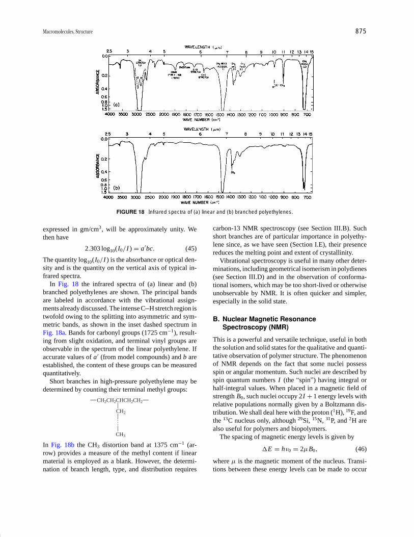
P1: GQT/LBX P2: GQT/MBQ QC: FYD Final Pages
Encyclopedia of Physical Science and Technology EN008C-602 July 25, 2001 20:31
Macromolecules, Structure 875
FIGURE 18 Infrared spectra of (a) linear and (b) branched polyethylenes.
expressed in gm/cm3, will be approximately unity. Wethen have
2.303 log10(I0 /I ) = a ′bc. (45)
The quantity log10(I0 /I ) is the absorbance or optical den-sity and is the quantity on the vertical axis of typical in-frared spectra.
In Fig. 18 the infrared spectra of (a) linear and (b)branched polyethylenes are shown. The principal bandsare labeled in accordance with the vibrational assign-ments already discussed. The intense C H stretch region istwofold owing to the splitting into asymmetric and sym-metric bands, as shown in the inset dashed spectrum inFig. 18a. Bands for carbonyl groups (1725 cm−1), result-ing from slight oxidation, and terminal vinyl groups areobservable in the spectrum of the linear polyethylene. Ifaccurate values of a ′ (from model compounds) and b areestablished, the content of these groups can be measuredquantitatively.
Short branches in high-pressure polyethylene may bedetermined by counting their terminal methyl groups:
CH2CH2CHCH2CH2
CH2
CH3
In Fig. 18b the CH3 distortion band at 1375 cm−1 (ar-row) provides a measure of the methyl content if linearmaterial is employed as a blank. However, the determi-nation of branch length, type, and distribution requires
carbon-13 NMR spectroscopy (see Section III.B). Suchshort branches are of particular importance in polyethy-lene since, as we have seen (Section I.E), their presencereduces the melting point and extent of crystallinity.
Vibrational spectroscopy is useful in many other deter-minations, including geometrical isomerism in polydienes(see Section III.D) and in the observation of conforma-tional isomers, which may be too short-lived or otherwiseunobservable by NMR. It is often quicker and simpler,especially in the solid state.
B. Nuclear Magnetic ResonanceSpectroscopy (NMR)
This is a powerful and versatile technique, useful in boththe solution and solid states for the qualitative and quanti-tative observation of polymer structure. The phenomenonof NMR depends on the fact that some nuclei possessspin or angular momentum. Such nuclei are described byspin quantum numbers I (the “spin”) having integral orhalf-integral values. When placed in a magnetic field ofstrength B0, such nuclei occupy 2I + 1 energy levels withrelative populations normally given by a Boltzmann dis-tribution. We shall deal here with the proton (1H), 19F, andthe 13C nucleus only, although 29Si, 15N, 31P, and 2H arealso useful for polymers and biopolymers.
The spacing of magnetic energy levels is given by
�E = hν0 = 2µB0, (46)
where µ is the magnetic moment of the nucleus. Transi-tions between these energy levels can be made to occur

P1: GQT/LBX P2: GQT/MBQ QC: FYD Final Pages
Encyclopedia of Physical Science and Technology EN008C-602 July 25, 2001 20:31
876 Macromolecules, Structure
by means of a resonant radio frequency field having a fre-quency ν0. In modern instruments, this resonant field issupplied as a pulse of radiofrequency energy and the res-onance signal appears as an oscillating current in the timedomain (“free induction decay” or fid), which must beFourier transformed by computer to the normal spectrumin the frequency domain.
The value of NMR to the chemist lies in the fact that atany particular value of ν0 all nuclei of a given species—say, all protons—do not resonate at exactly the same valueof B0 (or vice versa). Resonance actually occurs at slightlydifferent values of B0 for each type of proton, dependingupon its chemical binding and position in the molecule.The cause of this variation is the cloud of electrons abouteach nucleus. Protons attached to or near electronegativegroups such as OR, OH, OCOR, CO2R, or halogens expe-rience a lower electron density and appear at the left in theNMR spectrum, while those removed from such groups, asin hydrocarbon chains, appear at the right. Similar struc-tural relationships are observed for 13C nuclei, which alsoshow a marked dependence on conformation. These vari-ations are termed chemical shifts and are commonly ex-pressed in relation to tetramethylsilane (TMS) as the zeroof reference. For protons the total range of chemical shiftsin organic compounds is ∼10 ppm. For 13C it is muchgreater—over 200 ppm. The 13C nucleus constitutes only1.1% of naturally occurring carbon (12C has no spin and isnot observable by NMR) and consequently requires sub-stantial spectrum accumulation.
For any nucleus, the separation of chemical shifts, ex-pressed in hertz (Hz), is proportional to B0. An importantadvantage of high-field magnets is the improved resolu-tion of resonances and finer discrimination of structuralfeatures. Spectrometers employing superconducting mag-nets, operating at 200 to 500 MHz for protons, are bestsuited for studies of polymers in solution.
Another important parameter in NMR spectra is nu-clear coupling. If a nucleus has n sufficiently close equiv-alently coupled neighbors, its resonance will be split inton + 1 peaks, with intensities given by the coefficientsof the binomial expansion. Thus, one neighboring spinsplits the observed resonance to a doublet, two producea 1:2:1 triplet, three a 1:3:3:1 quartet, and so on. Thestrength of the coupling is denoted by J and expressedin hertz. Proton–proton couplings through three interven-ing bonds—termed “vicinal”—are strongly dependent onthe dihedral angle between the protons. This is dealt within Section IV.
C. Stereochemical Configuration
In Fig. 19 the 500-MHz proton spectra of poly(methylmethacrylate) prepared (a) with a free radical initiator and
FIGURE 19 500-MHz proton NMR spectra of predominantly (a)syndiotactic and (b) isotactic samples of poly(methyl methacry-late), observed in 10% chlorobenzene-d5 solution at 100◦C. Themethoxyl resonance is not shown, but appears as �3.4 ppm.
(b) with fluorenyllithium in toluene, an anionic initiator areshown. The profound effect of the nature of the initiatoris evident in the marked differences between these spec-tra. To interpret these spectra, let us consider the chainin terms of sequences of two monomer units or dyads.There are two possible types of dyads and they have dif-ferent symmetry properties. The syndiotactic or racemic(r ) dyad has a twofold axis of symmetry and consequentlythe two methylene protons are in equivalent environments.They therefore have the same chemical shift and appearas a singlet resonance despite strong two-bond or gem-inal coupling between them. The isotactic or meso (m)dyad has no symmetry axis, and so the two protons arenonequivalent and should in general give different chem-ical shifts.
R HA�
HA R
HB
HA RR
r m(PLANAR ZIGZAG CONFORMATION)
(a) (b)
When there is no vicinal coupling to neighboring protons,as is the case in poly(methyl methacrylate), the syndio-tactic sequences should exhibit a methylene singlet whilethe isotactic form should give two doublets, each with aspacing equal to the geminal coupling, ∼15 Hz. We seein Fig. 19 that the methylene spectrum of the anionically
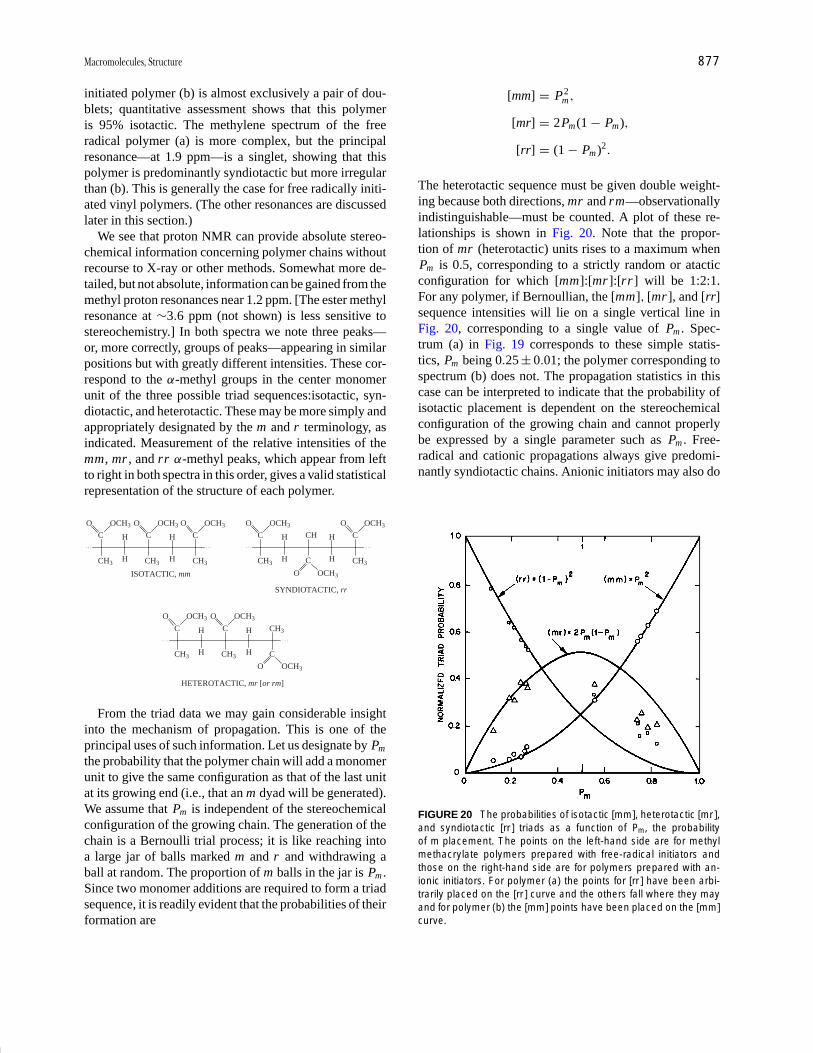
P1: GQT/LBX P2: GQT/MBQ QC: FYD Final Pages
Encyclopedia of Physical Science and Technology EN008C-602 July 25, 2001 20:31
Macromolecules, Structure 877
initiated polymer (b) is almost exclusively a pair of dou-blets; quantitative assessment shows that this polymeris 95% isotactic. The methylene spectrum of the freeradical polymer (a) is more complex, but the principalresonance—at 1.9 ppm—is a singlet, showing that thispolymer is predominantly syndiotactic but more irregularthan (b). This is generally the case for free radically initi-ated vinyl polymers. (The other resonances are discussedlater in this section.)
We see that proton NMR can provide absolute stereo-chemical information concerning polymer chains withoutrecourse to X-ray or other methods. Somewhat more de-tailed, but not absolute, information can be gained from themethyl proton resonances near 1.2 ppm. [The ester methylresonance at ∼3.6 ppm (not shown) is less sensitive tostereochemistry.] In both spectra we note three peaks—or, more correctly, groups of peaks—appearing in similarpositions but with greatly different intensities. These cor-respond to the α-methyl groups in the center monomerunit of the three possible triad sequences:isotactic, syn-diotactic, and heterotactic. These may be more simply andappropriately designated by the m and r terminology, asindicated. Measurement of the relative intensities of themm, mr , and rr α-methyl peaks, which appear from leftto right in both spectra in this order, gives a valid statisticalrepresentation of the structure of each polymer.
CH3
C
O OCH3
H
H CH3
C H
H CH3
C
ISOTACTIC, mm
CH3
C H
H
CH H
H CH3
C
SYNDIOTACTIC, rr
C
CH3
C H
H CH3
C H
H
CH3
C
HETEROTACTIC, mr [or rm]
O OCH3 O OCH3 O OCH3 O OCH3
O OCH3
O OCH3
O OCH3
O OCH3
From the triad data we may gain considerable insightinto the mechanism of propagation. This is one of theprincipal uses of such information. Let us designate by Pm
the probability that the polymer chain will add a monomerunit to give the same configuration as that of the last unitat its growing end (i.e., that an m dyad will be generated).We assume that Pm is independent of the stereochemicalconfiguration of the growing chain. The generation of thechain is a Bernoulli trial process; it is like reaching intoa large jar of balls marked m and r and withdrawing aball at random. The proportion of m balls in the jar is Pm .Since two monomer additions are required to form a triadsequence, it is readily evident that the probabilities of theirformation are
[mm] = P2m ,
[mr] = 2Pm(1 − Pm),
[rr] = (1 − Pm)2 .
The heterotactic sequence must be given double weight-ing because both directions, mr and rm—observationallyindistinguishable—must be counted. A plot of these re-lationships is shown in Fig. 20. Note that the propor-tion of mr (heterotactic) units rises to a maximum whenPm is 0.5, corresponding to a strictly random or atacticconfiguration for which [mm]:[mr ]:[rr ] will be 1:2:1.For any polymer, if Bernoullian, the [mm], [mr ], and [rr]sequence intensities will lie on a single vertical line inFig. 20, corresponding to a single value of Pm . Spec-trum (a) in Fig. 19 corresponds to these simple statis-tics, Pm being 0.25 ± 0.01; the polymer corresponding tospectrum (b) does not. The propagation statistics in thiscase can be interpreted to indicate that the probability ofisotactic placement is dependent on the stereochemicalconfiguration of the growing chain and cannot properlybe expressed by a single parameter such as Pm . Free-radical and cationic propagations always give predomi-nantly syndiotactic chains. Anionic initiators may also do
FIGURE 20 The probabilities of isotactic [mm], heterotactic [mr ],and syndiotactic [rr ] triads as a function of Pm, the probabilityof m placement. The points on the left-hand side are for methylmethacrylate polymers prepared with free-radical initiators andthose on the right-hand side are for polymers prepared with an-ionic initiators. For polymer (a) the points for [rr ] have been arbi-trarily placed on the [rr ] curve and the others fall where they mayand for polymer (b) the [mm] points have been placed on the [mm]curve.

P1: GQT/LBX P2: GQT/MBQ QC: FYD Final Pages
Encyclopedia of Physical Science and Technology EN008C-602 July 25, 2001 20:31
878 Macromolecules, Structure
FIGURE 21 Infrared spectra of predominantly (a) syndiotacticand (b) isotactic films of polymethyl methacrylate.
so if strongly complexing ether solvents such as dioxaneor glycol dimethyl ether are employed rather than hydro-carbon solvents as in polymer (b) of Fig. 19.
Vibrational spectra also reveal stereochemical differ-ences. In Fig. 21 infrared spectra of films of predominantlysyndiotactic (a) and isotactic (b) methyl methacrylatepolymers are shown. In addition to other smaller differ-ences, there is a conspicuous band at 1060 cm−1 in thesyndiotactic polymer spectrum (arrow), which is absentin that of the isotactic polymer. Such observations canserve as quick measures of chain stereochemistry, but ingeneral infrared is not as discriminating nor as quantitativeas NMR.
It is evident that in the spectra of Fig. 19 there is finestructure in both the methylene and methyl regions that wehave not discussed. In spectrum (a) this corresponds prin-cipally to residual resonances of the stereoirregular por-tions of the chains; in (b) such residual resonances are lessconspicuous. These arise from sensitivity to longer stereo-chemical sequences than dyad and triad. In Table III planarzigzag projections of such sequences, together with theirfrequency of occurrence as a function of Pm , assumingBernoullian propagation are shown. The tetrads—and all“even-ads”—refer to observations of β-methylene protons(or β carbons), while the “odd-ads” refer to substituents onthe α-carbons (or α-carbons themselves). Resonances fortetrad sequences or higher even-ads should appear as finestructure in the dyad spectra, while pentad sequences orhigher odd-ads should appear as fine structures on the triadresonances. The assignments to longer sequences as indi-cated on the spectra are based on Bernoullian probabilitiesin spectrum (a); those in spectrum (b) are primarily basedon (a). It may be noted that r -centered tetrads (e.g., mrr)
do not necessarily appear as singlets if the sequence as awhole lacks a twofold axis.
The numbers of observationally distinguishable config-urational sequences, or n-ads, designated N (n), obey therelationship
n 2 3 4 5 6 7 8 9
N (n) 2 3 6 10 20 36 72 136
or in general
N (n) = 2n −2 + 2m −1 , (47)
where m = n /2 if n is even and m = (n − 1)/2 if n is odd.Discrimination of these longer sequences is unlikely to bepossible beyond n = 6 (hexads) or n = 7 (heptads). Theobservation of such sequences permits rather searchingtests of polymerization mechanisms.
Another example is provided by polypropylene, partic-ularly instructive as it is one of the few vinyl polymersthat can be prepared in both
CH CH2[ [
CH3
� �n
isotactic and syndiotactic forms with coordination cata-lysts. The proton spectra are relatively complex becauseof vicinal coupling between α and β protons and α andmethyl protons as well as geminal methylene proton cou-pling in isotactic sequences. In Fig. 22, 220-MHz protonspectra of isotactic (a) and syndiotactic (b) polypropyleneare shown. The β protons of the syndiotactic polymer ap-pear as a triplet at 1.03 ppm corresponding to a singlechemical shift and J-coupling to two neighboring α pro-tons. In the isotactic polymer they appear as widely spacedmultiplets at 1.27 and 0.87 ppm, corresponding to syn andanti positions in the trans–trans conformation:
(ANTI)HH
H CH3 H
(SYN)
CH3
Analysis of these spectra yields the following values forthe vicinal main-chain couplings (in both polymers thevicinal CH3 Hα coupling is 5 Hz and germinal methyleneproton coupling is −13.5 Hz):
Isotactic
JHαHsyn: 6.0 Hz
JHαHanti: 7.0 Hz
Syndiotactic
J CH2 CH2: 4.8, 8.3 Hz
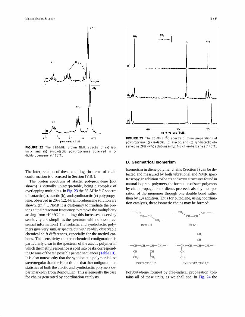
P1: GQT/LBX P2: GQT/MBQ QC: FYD Final Pages
Encyclopedia of Physical Science and Technology EN008C-602 July 25, 2001 20:31
Macromolecules, Structure 879
FIGURE 22 The 220-MHz proton NMR spectra of (a) iso-tactic and (b) syndiotactic polypropylenes observed in o-dichlorobenzene at 165◦C.
The interpretation of these couplings in terms of chainconformation is discussed in Section IV.B.1.
The proton spectrum of atactic polypropylene (notshown) is virtually uninterpretable, being a complex ofoverlapping multiplets. In Fig. 23 the 25-MHz 13C spectraof isotactic (a), atactic (b), and syndiotactic (c) polypropy-lene, observed in 20% 1,2,4-trichlorobenzene solution areshown. (In 13C NMR it is customary to irradiate the pro-tons at their resonant frequency to remove the multiplicityarising from 1H-13C J-coupling; this increases observingsensitivity and simplifies the spectrum with no loss of es-sential information.) The isotactic and syndiotactic poly-mers give very similar spectra but with readily observablechemical shift differences, especially for the methyl car-bons. This sensitivity to stereochemical configuration isparticularly clear in the spectrum of the atactic polymer inwhich the methyl resonance is split into peaks correspond-ing to nine of the ten possible pentad sequences (Table III).It is also noteworthy that the syndiotactic polymer is lessstereoregular than the isotactic and that the configurationalstatistics of both the atactic and syndiotactic polymers de-part markedly from Bernoullian. This is generally the casefor chains generated by coordination catalysts.
FIGURE 23 The 25-MHz 13C spectra of three preparations ofpolypropylene: (a) isotactic, (b) atactic, and (c) syndiotactic ob-served as 20% (w/v) solutions in 1,2,4-trichlorobenzene at 140◦C.
D. Geometrical Isomerism
Isomerism in diene polymer chains (Section I) can be de-tected and measured by both vibrational and NMR spec-troscopy. In addition to the cis and trans structures found innatural isoprene polymers, the formation of such polymersby chain propagation of dienes proceeds also by incorpo-ration of the monomer through one double bond ratherthan by 1,4 addition. Thus for butadiene, using coordina-tion catalysts, these isomeric chains may be formed:
CH2
CH CHCH2
CH2
CH CH
trans-1,4
CH2
cis-1,4
CH
ISOTACTIC 1,2
CH2 CH CH2
CH
CH2
CH
CH2
CH
SYNDIOTACTIC 1,2
CH2 CH CH2
CH
CH2
CH
CH2
Polybutadiene formed by free-radical propagation con-tains all of these units, as we shall see. In Fig. 24 the
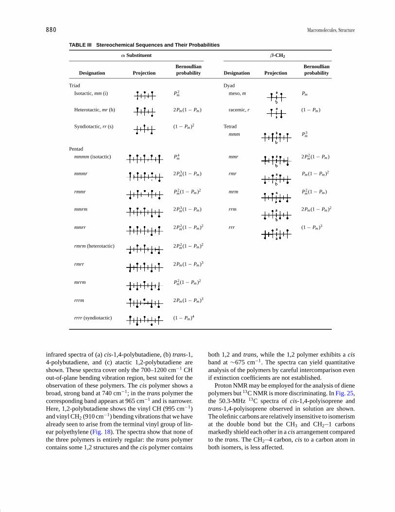
P1: GQT/LBX P2: GQT/MBQ QC: FYD Final Pages
Encyclopedia of Physical Science and Technology EN008C-602 July 25, 2001 20:31
880 Macromolecules, Structure
TABLE III Stereochemical Sequences and Their Probabilities
α Substituent β-CH2
Bernoullian BernoullianDesignation Projection probability Designation Projection probability
Triad Dyad
Isotactic, mm (i) P2m meso, m Pm
Heterotactic, mr (h) 2Pm (1 − Pm ) racemic, r (1 − Pm )
Syndiotactic, rr (s) (1 − Pm )2 Tetrad
mmm P3m
Pentad
mmmm (isotactic) P4m mmr 2P2
m (1 − Pm )
mmmr 2P3m (1 − Pm ) rmr Pm (1 − Pm )2
rmmr P2m (1 − Pm )2 mrm P2
m (1 − Pm )
mmrm 2P3m (1 − Pm ) rrm 2Pm (1 − Pm )2
mmrr 2P2m (1 − Pm )2 rrr (1 − Pm )3
rmrm (heterotactic) 2P2m (1 − Pm )2
rmrr 2Pm (1 − Pm )3
mrrm P2m (1 − Pm )2
rrrm 2Pm (1 − Pm )3
rrrr (syndiotactic) (1 − Pm )4
infrared spectra of (a) cis-1,4-polybutadiene, (b) trans-1,4-polybutadiene, and (c) atactic 1,2-polybutadiene areshown. These spectra cover only the 700–1200 cm−1 CHout-of-plane bending vibration region, best suited for theobservation of these polymers. The cis polymer shows abroad, strong band at 740 cm−1; in the trans polymer thecorresponding band appears at 965 cm−1 and is narrower.Here, 1,2-polybutadiene shows the vinyl CH (995 cm−1)and vinyl CH2 (910 cm−1) bending vibrations that we havealready seen to arise from the terminal vinyl group of lin-ear polyethylene (Fig. 18). The spectra show that none ofthe three polymers is entirely regular: the trans polymercontains some 1,2 structures and the cis polymer contains
both 1,2 and trans, while the 1,2 polymer exhibits a cisband at ∼675 cm−1. The spectra can yield quantitativeanalysis of the polymers by careful intercomparison evenif extinction coefficients are not established.
Proton NMR may be employed for the analysis of dienepolymers but 13C NMR is more discriminating. In Fig. 25,the 50.3-MHz 13C spectra of cis-1,4-polyisoprene andtrans-1,4-polyisoprene observed in solution are shown.The olefinic carbons are relatively insensitive to isomerismat the double bond but the CH3 and CH2 1 carbonsmarkedly shield each other in a cis arrangement comparedto the trans. The CH2 4 carbon, cis to a carbon atom inboth isomers, is less affected.

P1: GQT/LBX P2: GQT/MBQ QC: FYD Final Pages
Encyclopedia of Physical Science and Technology EN008C-602 July 25, 2001 20:31
Macromolecules, Structure 881
FIGURE 24 Out-of-plane bending bands in the infrared spectraof (a) cis-1,4-polybutadiene, (b) trans-1,4-polybutadiene, and (c)1,2-polybutadiene.
Spectrum (a) is that of natural rubber or hevea brasilien-sis. The biochemical pathway to natural rubber is an enzy-matic process in which isoprene as such plays no part. Thepolymer is highly stereoregular, no trace of the trans struc-ture being observable. Synthetic cis-1,4-polyisoprene isproduced commercially using lithium alkyls or Ziegler–Natta catalysts. It contains 2–6% of trans units.
Chains of mixed structure exhibit more complex spectrabecause of sequence effects. In Fig. 26 the 50.3-MHz 13Cspectrum of a polybutadiene produced by free-radicalinitiation is shown. At the left (a) is the region of olefiniccarbon resonance, not fully analyzed. The olefinic carbonsinglets of the pendant vinyl groups flank those of the 1,4units. At the right (b) are the aliphatic carbon resonances—
mainly 1,4 (and 1,2) methylene groups. This part of thespectrum is shown at two values of gain—1X and 5X—to show the small resonances of the sequences contain-ing 1,2 units. The major peak (b) corresponds to centralmethylenes in cis–cis units; the principal peak (d) is thatof the central 1,4-unit methylene group in trans–trans andtrans–cis units, not discriminated. Peaks (a), (c), (e), and(m) correspond to sequences involving 1,4 units and one1,2 unit, while the very small resonances (f ) through (l)represent sequences containing two 1,2 units. The overallcomposition of the polymer is 23% cis-1,4, 58% trans-1,4, and 19% 1,2. Spectrum (c) is a computer simulationof (b) based on the assumption of a random distribution ofunits in these proportions. The satisfactory fit shows thatfree-radical propagation in butadiene polymerization is aBernoullian process with regard to the generation of theseisomeric structures.
It has been observed by infrared spectroscopy thatthe trans-1,4 content of free-radical polybutadiene orbutadiene–styrene copolymers increases as the polymer-ization temperature is lowered—from ∼51% at 97◦C to84% at −18◦C. Butadiene–styrene copolymers in 75:25mole ratio are produced commercially in emulsion as SBRsynthetic rubber (see Table II). Most of it is produced atlow temperature, because the higher trans-1,4 content im-proves its tensile strength and mechanical properties. Byusing rhodium salts in aqueous solution very highly stere-ospecific trans-1,4-polybutadiene can be prepared.
E. Copolymer Structure
A very important structural variable is provided by ourability to synthesize not only homopolymers with asingle type of monomer unit but also copolymers havingchains composed of two or more comonomer units. (Wehave seen, however, that even homopolymers may havedifferent isomeric units and may be regarded as copoly-mers, although their composition is not so readily con-trolled as in true copolymerization.) Copolymers arebroadly divided into three types, as shown in Fig. 1b: ran-dom, block, and graft. Block and graft copolymers con-tain relatively long sequences of one monomer bonded tosimilar sequences of another. Although they are of majorscientific and technological interest, their overall compo-sition is usually known from their method of synthesis, andthey do not present microstructural problems essentiallydifferent from those of homopolymers. Our attention willbe confined to the random type, in which two or more typesof comonomer units are present in each chain. We shalldiscuss only copolymers of vinyl (or diene) monomers.Copolyesters and copolyamides are also significant buttheir composition is also usually readily predictable fromthe ratio of comonomers employed.
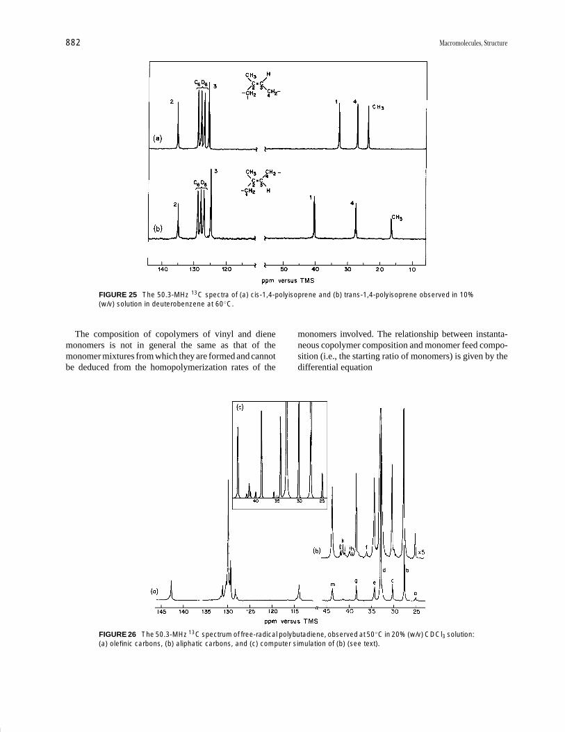
P1: GQT/LBX P2: GQT/MBQ QC: FYD Final Pages
Encyclopedia of Physical Science and Technology EN008C-602 July 25, 2001 20:31
882 Macromolecules, Structure
FIGURE 25 The 50.3-MHz 13C spectra of (a) cis-1,4-polyisoprene and (b) trans-1,4-polyisoprene observed in 10%(w/v) solution in deuterobenzene at 60◦C.
The composition of copolymers of vinyl and dienemonomers is not in general the same as that of themonomer mixtures from which they are formed and cannotbe deduced from the homopolymerization rates of the
FIGURE 26 The 50.3-MHz 13C spectrum of free-radical polybutadiene, observed at 50◦C in 20% (w/v) CDCl3 solution:(a) olefinic carbons, (b) aliphatic carbons, and (c) computer simulation of (b) (see text).
monomers involved. The relationship between instanta-neous copolymer composition and monomer feed compo-sition (i.e., the starting ratio of monomers) is given by thedifferential equation

P1: GQT/LBX P2: GQT/MBQ QC: FYD Final Pages
Encyclopedia of Physical Science and Technology EN008C-602 July 25, 2001 20:31
Macromolecules, Structure 883
d[M1]
d[M2]= [M1]
[M2]
{r1[M1] + [M2]
r2[M2] + [M1]
}, (48)
where M1 and M2 represent the two comonomers. The leftside of this equation gives the ratio of the rates at which thetwo monomers enter the copolymer, which in turn mustrepresent the composition of the copolymer being formedat any instant. The ratio [M1]/[M2] is the mole ratio ofmonomers in the feed. The quantities r1 and r2 are thereactivity ratios, defined as the ratios of propagation rateconstants:
r1 = k11/k12, r2 = k22/k21.
Here, k11 is the rate constant for the addition of monomer1 to a growing chain ending in a monomer 1 unit; k12 is therate constant for the addition of monomer 2 to the grow-ing chain ending in monomer 1; k21 and k22 are the corre-sponding terms for growing chains ending in a monomer2 unit.
Equation (48) is the copolymer equation in terms of themolar concentrations of the monomers. It is usually moreconvenient to express this relationship in terms of the molefraction in both feed and copolymer. The feed mole ratiofor monomer 1 is given by
f1 = 1 − f2 = [M1]
[M1] + [M2]. (49)
The instantaneous copolymer composition is given by
F1 = 1 − F2 = d[M1]
d[M1] + d[M2], (50)
from which
F1 = r1 f 21 + f1 f2
r1 f 21 + 2 f1 f2 + r2 f 2
2
. (51)
(A parallel, but redundant, equation expresses F2.)We have stated that these relationships deal with theinstantaneous composition of the copolymer. Since thecomonomers generally do not enter the polymer in thesame ratio as in the feed, the latter will drift in composi-tion as copolymerization proceeds, becoming depleted in
Dyads
m1m1 m1m2(or m2m1) m2m2
Triads
m1m1m1 m2m2m2
m1m1m2(or m2m1m1) m1m2m2(or m2m2m1)
m2m1m2 m1m2m1
Tetrads
m1m1m1m1 m1m1m2m1(m1m2m1m1) m2m2m2m2
m1m1m1m2(m2m1m1m1) m1m1m2m2(m2m2m1m1) m2m2m2m1(m1m2m2m2)
m2m1m2m1(m1m2m1m2)
m2m1m1m2 m2m1m2m2(m2m2m1m2) m1m2m2m1
the more reactive comonomer. As a result, the higher themonomer conversion the more heterogeneous the product.This in no way affects the determination of the overallcomposition or microstructure of the product but makesit more difficult to interpret in terms of relative reactiv-ities. It is therefore customary in fundamental studies tolimit the conversion to about 5% or less, although drifts incomposition can be dealt with mathematically. In copoly-mer production on a practical scale, it is common prac-tice to achieve greater structural regularity by adjustingthe monomer input as the reaction proceeds. This usuallymeans withholding the more reactive monomer.
The detailed discussion of various copolymerizationcases will not concern us here. Traditionally, the determi-nation of reactivity ratios, which provide important infor-mation concerning the behavior of monomers and grow-ing chains, has required the determination of the overallcomonomer composition of copolymers prepared from aseries of feed ratios. Elemental analysis is most commonlyused. A number of computational and graphic methodsare employed to do this. It was realized very early thatthe theoretical treatment that predicts overall compositionalso predicts the frequency of occurrence of comonomersequences, but at that time there was no way to observeand measure these. This can now be readily done by NMR,and the older and cruder methods are giving way to thismore powerful approach. By NMR it is also possible toobserve copolymer stereochemistry (never considered inearlier work) and the presence of anomalous units. One canalso more readily detect deviations from the simple modelemployed here, in which only the terminal residue of agrowing chain determines its reactivity; the effect of thepenultimate unit, if any, may be clearly observed. Finally,it should be noted that by sequence measurements one candetermine reactivity ratios from only a single copolymerprovided the feed ratio is known. It may still be desirableto observe a range of compositions to assist in resonanceassignments but it is not in principle essential.
For a random copolymerization, dyad, triad, and tetradsequences may be represented (ignoring stereochemistry)as

P1: GQT/LBX P2: GQT/MBQ QC: FYD Final Pages
Encyclopedia of Physical Science and Technology EN008C-602 July 25, 2001 20:31
884 Macromolecules, Structure
The dyad probabilities (i.e., frequencies of occurrence) aregiven by
[m1m1] = F1 P11 , (52)
[m1m2](or [m2m1]) = 2F1 P12 = 2F1(1 − P11)
= 2F2 P21 = 2F2(1 − P22), (53)
[m2m2] = F2 P22 . (54)
Here, as we have seen, F1 and F2 are the overall molefractions of m1 and m2, respectively.
[m1m1m1] = F1 P211 , (55)
[m1m1m2](or [m2m1m1]) = 2F1 P11(1 − P11), (56)
[m2m1m2] = F2(1 − P22)(1 − P11).
(57)
The quantity P11 expresses the conditional probability thata chain ending in m1 will add another m1, and P22 ex-presses the corresponding probability for m2. Here, P12 isthe probability that a chain ending in m1 will add m2, equalto the probability that it will not add m1 (i.e., 1 − P11). Cor-responding to the four rate constants k11 , k12 , k21, and k22
are the four probabilities P11, P12, P21, and P22, related by
P11 + P12 = 1, (58)
P21 + P22 = 1, (59)
since a growing chain has only two choices. We choose toemploy P11 and P22; it can be shown that they are givenin terms of monomer feed mole fractions and reactivityratios by
P11 = r1 f1
1 − f1(1 − r1) , (60)
P22 = r2 f2
1 − f2(1 − r2) , (61)
from which
r1 = (1 − f1)[m1m1]
f1(F1 − [m1m1]) , (62)
r2 = (1 − f2)[m2m2]
f2(F2 − [m2m2]) . (63)
Entirely analogous relationships apply to triad and tetradsequences.
The system vinylidene chloride (m1): isobutylene (m2)is appropriate to consider since the copolymer has noasymmetric carbons and no vicinal J coupling. The protonNMR spectrum thus conveys only compositional sequenceinformation. In Fig. 27, 60-MHz proton NMR spectra ofthe homopolymers (a) and (b) are shown. The homopoly-mer of vinylidene chloride gives a single resonance for the
FIGURE 27 The 60-MHz proton spectra of (a) polyvinylidenechloride, (b) polyisobutylene, and (c) vinylidene chloride (m1):isobutylene (m2) copolymer containing 70 mol % m1. Peaks areidentified with monomer tetrad sequences (a) m1m1m1m1; (2)m1m1m1m2; (3) m2m1m1m2; (4) m1m1m2m1; (5) m2m1m2m1; (6)m1m1m2m2; (7) m2m1m2m2. [From Hellwege, K. H., Johnsen, U.,and Kolbe, K. (1966). Kolloid-Z. 214, 45.]
methylene protons (a); the homopolymer of isobutylene(which can be prepared with cationic but not with freeradical initiators) gives singlet resonances of 3:1 inten-sity for the methyl and methylene protons. The spectrumof a copolymer, prepared with a free-radical initiator andcontaining 70 mol% vinylidene chloride is shown in (c).The methylene resonances are grouped in three chemicalshift ranges: m1m1-centered peaks at low field; peaks ofmethylene protons in
C CH2 C
Cl
Cl
CH3
CH3
m1m2-centered units near 3 ppm; and CH2 and CH3 reso-nances of m2-centered sequences at high field. It is evidentthat tetrad sequences are involved (assignments given inthe figure caption). If only dyad sequences were distin-guished, there would be only three methylene resonancescorresponding to m1m1, m1m2(or m2m1), and m2m2 se-quences. The upfield isobutylene peaks show considerableoverlap and assignments here are less certain, but theseresonances are not required for the analysis.
From dyad resonances r1 and r2 may be calculated. Therelative intensity of the m1m1 resonances centered near3.6 ppm gives [m1m1] as 0.426, normalized over all dyad
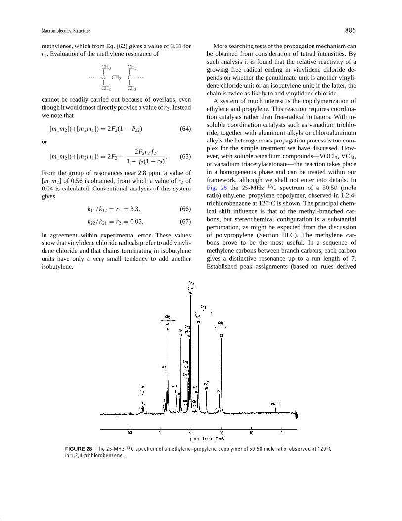
P1: GQT/LBX P2: GQT/MBQ QC: FYD Final Pages
Encyclopedia of Physical Science and Technology EN008C-602 July 25, 2001 20:31
Macromolecules, Structure 885
methylenes, which from Eq. (62) gives a value of 3.31 forr1. Evaluation of the methylene resonance of
C CH2 C
CH3
CH3
CH3
CH3
cannot be readily carried out because of overlaps, eventhough it would most directly provide a value of r2. Insteadwe note that
[m1m2](+[m2m1]) = 2F2(1 − P22) (64)
or
[m1m2](+[m2m1]) = 2F2 − 2F2r2 f2
1 − f2(1 − r2) . (65)
From the group of resonances near 2.8 ppm, a value of[m1m2] of 0.56 is obtained, from which a value of r2 of0.04 is calculated. Conventional analysis of this systemgives
k11 /k12 = r1 = 3.3, (66)
k22 /k21 = r2 = 0.05, (67)
in agreement within experimental error. These valuesshow that vinylidene chloride radicals prefer to add vinyli-dene chloride and that chains terminating in isobutyleneunits have only a very small tendency to add anotherisobutylene.
FIGURE 28 The 25-MHz 13C spectrum of an ethylene–propylene copolymer of 50:50 mole ratio, observed at 120◦Cin 1,2,4-trichlorobenzene.
More searching tests of the propagation mechanism canbe obtained from consideration of tetrad intensities. Bysuch analysis it is found that the relative reactivity of agrowing free radical ending in vinylidene chloride de-pends on whether the penultimate unit is another vinyli-dene chloride unit or an isobutylene unit; if the latter, thechain is twice as likely to add vinylidene chloride.
A system of much interest is the copolymerization ofethylene and propylene. This reaction requires coordina-tion catalysts rather than free-radical initiators. With in-soluble coordination catalysts such as vanadium trichlo-ride, together with aluminum alkyls or chloroaluminumalkyls, the heterogeneous propagation process is too com-plex for the simple treatment we have discussed. How-ever, with soluble vanadium compounds—VOCl3, VCl4,or vanadium triacetylacetonate—the reaction takes placein a homogeneous phase and can be treated within ourframework, although we shall not enter into details. InFig. 28 the 25-MHz 13C spectrum of a 50:50 (moleratio) ethylene–propylene copolymer, observed in 1,2,4-trichlorobenzene at 120◦C is shown. The principal chem-ical shift influence is that of the methyl-branched car-bons, but stereochemical configuration is a substantialperturbation, as might be expected from the discussionof polypropylene (Section III.C). The methylene car-bons prove to be the most useful. In a sequence ofmethylene carbons between branch carbons, each carbongives a distinctive resonance up to a run length of 7.Established peak assignments (based on rules derived

P1: GQT/LBX P2: GQT/MBQ QC: FYD Final Pages
Encyclopedia of Physical Science and Technology EN008C-602 July 25, 2001 20:31
886 Macromolecules, Structure
from extensive study of model hydrocarbons) are shownhere:
H CH3 CH3H
45.5-46.5
��
14.8
��, ��
H CH3
CH3H
��, ��, �� ���, ��, ��, ���
H CH3
37.9
CH3H24.9
H CH3
37.5
27.8
CH3H
���, ���, ��, ���, ���
30.7
H CH3
37.5
27.4 CH3H
���, ���, ���, ���, ���, ���
30.4
H CH3
37.5
27.4
CH3H
���, ���, ���, ����, ���, ���, ���
30.0
30.4
H CH3
37.5
27.4CH3H
The Greek letter designations indicate the position ofthe nearest branch carbon. A plus sign indicates that thebranch is at the δ or more distant position. Those methy-lene carbons that are four or more carbons removed froma branch carbon give the same chemical shift (30.0 ppm).Propylene inversions can be clearly identified through thepresence of methylene sequences two and four carbons inlength. From these assignments and using a mathematicalmodel of chain growth that treats inverted propylene unitsas a third monomer, a complete analysis of the statisticaldistribution of sequences can be carried out. The extentof inversion is about 5%. A value of the product of reac-tivity ratios r1r2 0.35 ± 0.04 was found. This correspondsto a propagation process not far from random but with amoderate tendency toward alternation of monomer units.
F. Regioregularity
In the earlier days of polymer science it was not knownwhether vinyl polymers had head-to-tail or head-to-head:tail-to-tail structures (Section I). Because spectroscopy—
CH2 CHF CH2 CHF CH2 CHF CHF CH2 CH2 CHF CH2 CHFA A B C D A
either vibrational or NMR—was not available, chemi-cal methods had to be employed. Thus, to determinethe structure of poly(vinyl chloride) the Freund reactionwas employed. This employed metallic zinc and was be-lieved to be specific for the removal of chlorine atoms in1,3 positions:
CH
CH2
CH
Cl Cl� Zn CH CH
CH2
� ZnCl2
It thus would not proceed if the structure were head-to-head: tail-to-tail. Since it did in fact remove most of thechlorine from poly(vinyl chloride), it was concluded thatthe polymer had a head-to-tail structure. NMR confirmsthis conclusion.
A more subtle chemical approach has been applied topoly(vinyl alcohol). Here, it is assumed that the predom-inant structure is head-to-tail and the question posed wasthe frequency of occurrence of the occasional invertedunit. It is assumed that periodic acid reacts only with 1,2-glycol units and not with 1,3 units:
CH2 CH CH2 CH CH CH2 CH2 CH
OH OH OH
HIO4 CH2CHO � OCHCH2
OH
Inverted units in poly(vinyl alcohol) thus lead to chainscission, the extent of which can be measured by the re-duction of solution viscosity (Section II.F). It is concludedthat 1–2% of head-to-head units are present, this mode ofpropagation increasing with temperature.
Fluorine-substituted ethylenes are particularly subjectto the generation of inverted units, presumably becausefluorine atoms are relatively undemanding sterically. Atthe same time, the physical properties of their polymersmay depend strongly on the presence of such units. Thepresence of 19F offers an additional means for detailedstudy, as 19F chemical shifts are highly sensitive to struc-tural variables. Poly(vinyl fluoride), a commercial plas-tic having high resistance to weathering, has a substan-tial proportion of head-to-head units. The 188-MHz 19Fspectrum of a commercial polymer is shown in Fig. 29.The 19F H J-coupling multiplicity has been removed byproton irradiation as in 13C spectroscopy (Section III.C).The resonance assignments, designated by capital letters,are:
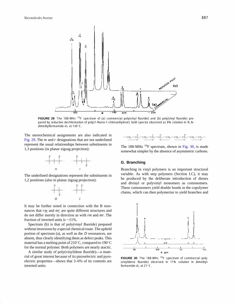
P1: GQT/LBX P2: GQT/MBQ QC: FYD Final Pages
Encyclopedia of Physical Science and Technology EN008C-602 July 25, 2001 20:31
Macromolecules, Structure 887
FIGURE 29 The 188-MHz 19F spectrum of (a) commercial poly(vinyl fluoride) and (b) poly(vinyl fluoride) pre-pared by reductive dechlorination of poly(1-fluoro-1-chloroethylene): both spectra observed as 8% solution in N,N-dimethylformamide-d7 at 130◦C.
The stereochemical assignments are also indicated inFig. 29. The m and r designations that are not underlinedrepresent the usual relationships between substituents in1,3 positions (in planar zigzag projection):
F F F
Fm r
The underlined designations represent the substituents in1,2 positions (also in planar zigzag projection):
F
F
F
m r
F
It may be further noted in connection with the B reso-nances that rm and mr are quite different structures anddo not differ merely in direction as with rm and mr. Thefraction of inverted units is ∼11%.
Spectrum (b) is that of poly(vinyl fluoride) preparedwithout inversions by a special chemical route. The upfieldportion of spectrum (a), as well as the D resonances, areabsent, thus clearly identifying them as defect peaks. Thismaterial has a melting point of 210◦C, compared to 190◦Cfor the normal polymer. Both polymers are nearly atactic.
A similar study of poly(vinylidene fluoride)—a mate-rial of great interest because of its piezoelectric and pyro-electric properties—shows that 3–6% of its contents areinverted units:
CH2 CF2 CH2 CF2 CF2 CH2 CH2 CF2 CH2 CF2
A C D B
The 188-MHz 19F spectrum, shown in Fig. 30, is madesomewhat simpler by the absence of asymmetric carbons.
G. Branching
Branching in vinyl polymers is an important structuralvariable. As with step polymers (Section I.C), it maybe produced by the deliberate introduction of dienesand divinyl or polyvinyl monomers as comonomers.These comonomers yield double bonds in the copolymerchains, which can then polymerize to yield branches and
FIGURE 30 The 188-MHz 19F spectrum of commercial poly-(vinylidene fluoride) observed in 11% solution in dimethyl-formamide-d7 at 21◦C.
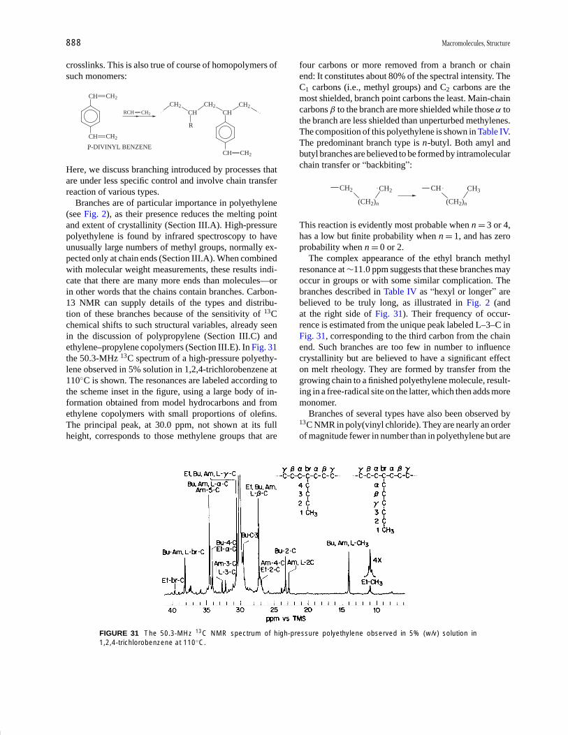
P1: GQT/LBX P2: GQT/MBQ QC: FYD Final Pages
Encyclopedia of Physical Science and Technology EN008C-602 July 25, 2001 20:31
888 Macromolecules, Structure
crosslinks. This is also true of course of homopolymers ofsuch monomers:
CH CH2
CH
CH2RCH
CH2
CHCH2
CHCH2
R
CH CH2
CH2
P-DIVINYL BENZENE
Here, we discuss branching introduced by processes thatare under less specific control and involve chain transferreaction of various types.
Branches are of particular importance in polyethylene(see Fig. 2), as their presence reduces the melting pointand extent of crystallinity (Section III.A). High-pressurepolyethylene is found by infrared spectroscopy to haveunusually large numbers of methyl groups, normally ex-pected only at chain ends (Section III.A). When combinedwith molecular weight measurements, these results indi-cate that there are many more ends than molecules—orin other words that the chains contain branches. Carbon-13 NMR can supply details of the types and distribu-tion of these branches because of the sensitivity of 13Cchemical shifts to such structural variables, already seenin the discussion of polypropylene (Section III.C) andethylene–propylene copolymers (Section III.E). In Fig. 31the 50.3-MHz 13C spectrum of a high-pressure polyethy-lene observed in 5% solution in 1,2,4-trichlorobenzene at110◦C is shown. The resonances are labeled according tothe scheme inset in the figure, using a large body of in-formation obtained from model hydrocarbons and fromethylene copolymers with small proportions of olefins.The principal peak, at 30.0 ppm, not shown at its fullheight, corresponds to those methylene groups that are
FIGURE 31 The 50.3-MHz 13C NMR spectrum of high-pressure polyethylene observed in 5% (w/v) solution in1,2,4-trichlorobenzene at 110◦C.
four carbons or more removed from a branch or chainend: It constitutes about 80% of the spectral intensity. TheC1 carbons (i.e., methyl groups) and C2 carbons are themost shielded, branch point carbons the least. Main-chaincarbons β to the branch are more shielded while those α tothe branch are less shielded than unperturbed methylenes.The composition of this polyethylene is shown in Table IV.The predominant branch type is n-butyl. Both amyl andbutyl branches are believed to be formed by intramolecularchain transfer or “backbiting”:
CH2
(CH2)n
CH2 CH
(CH2)n
CH3
This reaction is evidently most probable when n = 3 or 4,has a low but finite probability when n = 1, and has zeroprobability when n = 0 or 2.
The complex appearance of the ethyl branch methylresonance at ∼11.0 ppm suggests that these branches mayoccur in groups or with some similar complication. Thebranches described in Table IV as “hexyl or longer” arebelieved to be truly long, as illustrated in Fig. 2 (andat the right side of Fig. 31). Their frequency of occur-rence is estimated from the unique peak labeled L–3–C inFig. 31, corresponding to the third carbon from the chainend. Such branches are too few in number to influencecrystallinity but are believed to have a significant effecton melt rheology. They are formed by transfer from thegrowing chain to a finished polyethylene molecule, result-ing in a free-radical site on the latter, which then adds moremonomer.
Branches of several types have also been observed by13C NMR in poly(vinyl chloride). They are nearly an orderof magnitude fewer in number than in polyethylene but are

P1: GQT/LBX P2: GQT/MBQ QC: FYD Final Pages
Encyclopedia of Physical Science and Technology EN008C-602 July 25, 2001 20:31
Macromolecules, Structure 889
TABLE IV Branching in High-Pressure PolyethyleneMn = 18,400, Mw = 129,000
Number of branches perTypes of branch 1000 backbone carbons
CH3 0.0
CH2CH3 1.0
CH2CH2CH3 0.0
CH2CH2CH2CH3 9.6
CH2CH2CH2CH2CH3 3.6
Hexyl and longer 5.6
Total 19.8
significant because some of them—those with a tertiarychlorine—are believed to be sites for the initiation ofthe
Cl
C CH2CH2
CH2
CHCl
chemical decomposition of the polymer. Poly(vinyl chlo-ride) is a valuable material, used in very large volumefor molding and electrical insulation. It is fire resistantand relatively cheap, but when heated is subject to lossof hydrogen chloride, leading to the formation of deeplycolored polyene structures:
·· CH2CHClCH2CHCl ·· �→·· CH CHCH CH ·· + 2HCl
The reaction is more complicated than this simple repre-sentation suggests and is believed to be sensitized by thepresence of labile centers such as a tertiary chlorine.
Branches are an integral part of other polymers suchas star polymers and dendrimers. Star polymers can havea variable number of arms with a controlled molecularweight. Dendrimer can have a high molecular weight andmany functional end groups.
IV. CHAIN CONFORMATIONSOF MACROMOLECULES
A. Theoretical Introduction
We have already seen in Eq. (13) that the rms end-to-enddistance of a polymer chain is given by
〈r2 〉1/2 = lx1/2 or 〈r2 〉 = l2x ,
where l is the length of a monomer unit and x is the num-ber of monomer units. This relationship is derived fromrandom walk statistics and assumes that bond rotation isfree and that the bonds between two adjacent monomerunits can assume any angle. This model is called the freelyjointed chain and is clearly unreasonable for a polymer,where bond hybridization imposes restrictions on avail-able bond angles. However, it is qualitatively correct inthat any correlation between two monomer units must de-crease as the distance between the units is increased.
We can improve this model by imposing a restrictionon our hypothetical chain. If we allow the chain segmentsto rotate freely, but now fix the valence angles, we havewhat is known as a freely rotating chain. In this model,〈r2 〉 is given by
〈r2 〉 =(
1 − cos θ
1 + cos θ
)xl2 , (68)
where θ is the angle between successive bonds in a chain.For a tetrahedral chain, θ = 109◦ and 〈r2 〉 = 2xl2.
A further refinement is required to obtain a reasonablemodel for a polymer chain. In the restricted rotation model,we take into account the fact that there are intrachain hin-drances in a real polymer chain. The bond angles are fixedby virtue of hybridization, and the chain rotation is limitedto a few rotational isomeric states. We shall first illustratechain conformations with a simple model compound, andthen extend our treatment to a segment of a polyethylenechain.
Referring to Fig. 32, we see several conformationsof butane, generated by rotation about the C2 C3 bond.These are called gauche+, trans, and gauche− confor-mations and are usually abbreviated as g +, t , and g −.The available conformations are most easily visualizedin Newman diagrams, shown in Fig. 32(a). Looking downthe C2 C3 bond, the substituents are projected onto planesparallel to the paper. The C2 carbon is in front, and theC3 carbon, in this presentation, is obscured by the C2
carbon. The Newman diagrams clearly show that in thetrans arrangement, the bulky groups are opposite eachother, separated by a dihedral angle of 180◦. The gauche+
and gauche− conformations are formally generated by ro-tations about the C2 C3 bond. The bulky groups in thegauche conformations are separated by a dihedral angleof 60◦.
Figure 32(b) shows how the torsional potential of n-butane varies as a function of conformation. The lowestenergy conformation occurs when n-butane is in the transconformation. The population of n-butane in the eclipsedconformations, corresponding to the tops of the energybarriers, is negligible. The trans and gauche conformersinterchange very rapidly with each other, having lifetimesof approximately 10−10 sec at room temperature.

P1: GQT/LBX P2: GQT/MBQ QC: FYD Final Pages
Encyclopedia of Physical Science and Technology EN008C-602 July 25, 2001 20:31
890 Macromolecules, Structure
FIGURE 32 (a) Newman projections of the g−, t , and g + confor-mations of n-butane and (b) torsional potentials for rotation aboutthe central (C2 C3) bond in n-butane.
By virtue of its simple structure, n-butane has fewavailable conformations. Once we lengthen the chain byone carbon we immediately see that the description ofavailable conformations becomes more complicated. Inn-pentane we must now specify two rotational angles, φ1
and φ2:
H H
H H H H
CH3 CH31
423
tt�1 �2 0
H H
H H H CH3
CH3 H
tg�
�1 0 ;�2 �120
H H
H H HCH3
CH3 H
tg�
�1 0;�2 �120
H H
H H CH3
H H
g�g�
�1
H H
H HCH3
H H
�1 �120�2 �120
CH3
�2 �120
CH3
g�g�
�1 �2
Note that the tg+ and g +t conformations are identi-cal, and that the tg+ and tg− states are mirror images ofeach other. Also, the g +g + and g −g − conformations areequivalent, as are the g −g + and g +g − states.
The energy of a given rotational state of the C2 C2
bond depends on the rotational state of the C3 C4 bondand vice versa. We now need an energy map, ratherthan the simple diagram of Fig. 32, in order to visu-alize the energies of the various conformations of n-pentane. Such a map is shown in Fig. 33. This dia-gram indicates that the tt conformation (φ1 = φ2 = 0◦) hasthe lowest energy. Other low-energy conformations arethe tg+ and tg− states (φ1 = 0◦, φ2 = ±120◦). The g +g +
state (φ1 = φ2 = +120◦) is of lower energy than the g +g −
(φ1 = +120◦, φ2 = −120◦). This is because the methylgroups in the g +g + state experience neither attractivenor repulsive forces, whereas in the g +g − state themethyl groups are nearly eclipsed and experience severerepulsion.
It is important to note that although the g +g − (andg −g +) state is very unfavorable, there are local minimanear this conformation at φ1, φ2 = 77◦, −115◦ and 120◦,−70◦ (see Fig. 33).
The main difference between the n-butane andn-pentane cases is that there are only three-bond, or first-order interactions in n-butane, whereas in n-pentane thereare second-order interactions. These second-order inter-actions must be taken into account in polymer chains. Therotational isomeric state (RIS) model, introduced above, issuccessful in treating both the first-order and higher orderinteractions.
The RIS model is a statistical treatment of all possi-ble chain conformations in which the bond lengths andvalence angles are fixed. The conformation of a polymerchain of n bonds can be specified by assigning a rota-tional state to each of the n − 2 nonterminal bonds. Ifthere are v rotational states about each of n bonds, therewill be vn−2 possible conformational states. Even for thecommon case of v = 3, a chain of 20 bonds will have3.8 × 108 conformational states. The RIS model readilylends itself to computer calculation by matrix methods.Statistical weight matrices are used with the RIS model to
FIGURE 33 Energy map for n-pentane for rotation angles φ1 andφ2. The numbers on the contours refer to energies in kcal/mol. Theminima are indicated by x’s [From Abe, A., Jernigan, R. L., andFlory, P. J. (1966). J. Am. Chem. Soc. 88, 631.]

P1: GQT/LBX P2: GQT/MBQ QC: FYD Final Pages
Encyclopedia of Physical Science and Technology EN008C-602 July 25, 2001 20:31
Macromolecules, Structure 891
FIGURE 34 Representative conformations of polymers: (a) 31helix (gt)(gt)(gt) viewed down the helix axis; and (b) syndiotactic(gg)(t t) sequences found in polypropylene.
define the energies of various conformers. The matricesinclude the effects of both first- and second-order stericinteractions. Using the RIS model and matrix operations,any conformation-dependent property of a polymer chaincan be calculated, although such a calculation requiressome estimate of the bond rotational states and their asso-ciated energies.
A detailed account of RIS model and associated calcu-lations is beyond the scope of this article. However, wesummarize several of the conclusions concerning the re-lationship between structure and conformation of vinylpolymers that can be drawn from a combination of RIScalculations and experimental results. Isotactic chains tendto assume alternating gauche and trans rotational states.These · · · (gt)(gt)(gt) · · · sequences favor the formationof a 31 helix. [A 31 helix makes one turn for every threemonomer units. When viewed along the helix axis the 31
helix exhibits threefold symmetry, as shown in Fig. 34(a).]As we have seen, such helical sequences will have equalprobability of being either left- or right-handed. In so-lution these conformations will reverse chirality rapidlyand at random, as the conformation states have very shortlifetimes.
Syndiotactic chains, in contrast to the isotactic se-quences discussed above, generally favor tt conforma-tions. There is a substantial occurrence of helical confor-mations of the type · · · (gg)(tt) (gg)(tt) · · · . Figure 34(b)shows a view of this helix along the helix axis. This isa special case found for syndiotactic polypropylene. Weshall return to this structure later (Section IV.C.3). In so-lution the conformations responsible for such a helicalsequence also undergo rapid interconversions.
B. Experimental Observation of ChainConformation in Solution
Examples of the conformation-dependent properties thatcan be calculated from the RIS model include the dipolemoment, the molar Kerr constant, the characteristic ratio,
and the NMR chemical shift and other spectroscopic pa-rameters. In this section we shall describe briefly some ofthe methods for experimentally observing polymer chainconformations in solution. Combined with such experi-mental measurements, the results from RIS calculationsprovide valuable insight into the structure and conforma-tion of macromolecules.
1. The Characteristic Ratio, C∞
Recall from our previous discussion (Section II.F) thatthe intrinsic viscosity [η] is obtained by extrapolating thespecific viscosity, ηsp to zero concentration:
[η] = limC2→0
[η − η0
η0
]/c. (69)
In this expression, η and η0 are the polymer solution andsolvent viscosities, respectively, and c is the polymer con-centration in g/dL, or grams per deciliter.
Flory has shown that the intrinsic viscosity may also beexpressed as
[η] = φ〈r2〉3/2/M, (70)
where φ is a universal constant equal to approximately2.5 × 1021 and M is the polymer molecular weight.The mean squared end-to-end distance is 〈r2〉 (seeSection II.B.1), which in a non-θ solvent may be some-what greater than the unperturbed dimensions 〈r2〉. In realsolvents the degree of expansion of the molecular coil isdesignated as α, such that
〈r2〉 = α2〈r2〉. (71)
For a θ solvent, where the expanding effect of excludedvolume is exactly balanced by polymer–polymer interac-tions, α = 1.
The characteristic ratio C∞ is the ratio between the un-perturbed and the random walk dimensions and is given by
C∞ = 〈r2〉/xl2 (72)
where x is the number of chain segments and l is thelength of a single monomer unit, as before.
For all real polymers, C∞ is greater than unity and isa measure of departure from a freely jointed or freelyrotating model.
Substituting into Eq. (72) for 〈r2〉, we can obtain a re-lationship between C∞ and [η]:
C∞ = 1
xl2
[[η]θ M
φ
]2/3
(73)
If we let m be the monomer molecular weight,
C∞ = m
Ml2
[[η]θ M
φ
]2/3
(74)
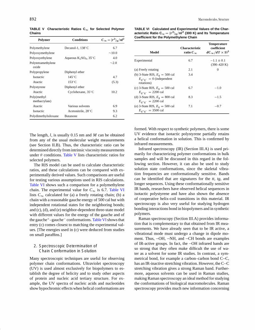
P1: GQT/LBX P2: GQT/MBQ QC: FYD Final Pages
Encyclopedia of Physical Science and Technology EN008C-602 July 25, 2001 20:31
892 Macromolecules, Structure
TABLE V Characteristic Ratios C∞ for Selected PolymerChains
Polymer Conditions C∞ = 〈r2 〉0 /nl2
Polymethylene Decanol-1, 138◦C 6.7
Polyoxymethylene ∼10.0
Polyoxyethylene Aqueous K2SO4, 35◦C 4.0
Polytetramethylene ∼2.0oxide
Polypropylene Diphenyl ether
Isotactic 145◦C 4.7
Atactic 153◦C (5.3)
Polystyrene Diphenyl ether
Atactic Cyclohexane, 35◦C 10.2
Poly(methylmethacrylate)
Atactic Various solvents 6.9
Isotactic Acetonitrile, 28◦C 9.3
Polydimethylsiloxane Butanone 6.2
The length, l, is usually 0.15 nm and M can be obtainedfrom any of the usual molecular weight measurements(see Section II.B). Thus, the characteristic ratio can bedetermined directly from intrinsic viscosity measurementsunder θ conditions. Table V lists characteristic ratios forselected polymers.
The RIS model can be used to calculate characteristicratios, and these calculations can be compared with ex-perimentally derived values. Such comparisons are usefulfor testing various assumptions used in RIS calculations.Table VI shows such a comparison for a polymethylenechain. The experimental value for C∞ is 6.7. Table VIlists C∞ calculated for (a) a freely rotating chain; (b) achain with a reasonable gauche energy of 500 cal but withindependent rotational states for the neighboring bonds;and (c), (d), and (e) neighbor-dependent three-state modelwith different values for the energy of the gauche and ofthe gauche+–gauche− conformations. Table VI shows thatentry (c) comes closest to matching the experimental val-ues. [The energies used in (c) were deduced from studieson small paraffins.]
2. Spectroscopic Determination ofChain Conformation in Solution
Many spectroscopic techniques are useful for observingpolymer chain conformations. Ultraviolet spectroscopy(UV) is used almost exclusively for biopolymers to es-tablish the degree of helicity and to study other aspectsof protein and nucleic acid tertiary structure. For ex-ample, the UV spectra of nucleic acids and nucleotidesshow hypochromic effects when helical conformations are
TABLE VI Calculated and Experimental Values of the Char-acteristic Ratio C∞ = 〈r 2〉0/nl 2 (300 K) and Its TemperatureCoefficient for the Polymethylene Chain
TemperatureCharacteristic coefficient
Model ratio C∞ dC∞/dT × 103
Experimental 6.7 −1.1 ± 0.1(390–420 K)
(a) Freely rotating 2.1 0
(b) 3-State RIS, Eg = 500 cal 3.4Eg+g− = 0 (independentrotations)
(c) 3-State RIS, Eg = 500 cal 6.7 −1.0Eg+g− = 2200 cal
(d) 3-State RIS, Eg = 800 cal 8.3 −1.5Eg+g− = 2200 cal
(e) 3-State RIS, Eg = 500 cal 7.1 −0.7Eg+g− = 3500 cal
formed. With respect to synthetic polymers, there is someUV evidence that isotactic polystyrene partially retainsa helical conformation in solution. This is confirmed byinfrared measurements.
Infrared spectroscopy (IR) (Section III.A) is used pri-marily for characterizing polymer conformations in bulksamples and will be discussed in this regard in the fol-lowing section. However, it can also be used to studysolution state conformations, since the skeletal vibra-tion frequencies are conformationally sensitive. Bandscan be identified that are signatures for the tt, tg, andlonger sequences. Using these conformationally sensitiveIR bands, researchers have observed helical sequences inisotactic polystyrene and have also shown the absenceof cooperative helix-coil transitions in this material. IRspectroscopy is also very useful for studying hydrogenbonding interactions bond in biopolymers and in syntheticpolymers.
Raman spectroscopy (Section III.A) provides informa-tion that is complementary to that obtained from IR mea-surements. We have already seen that to be IR active, avibrational mode must undergo a change in dipole mo-ment. Thus, OH, NH, and CH bonds are examplesof IR-active groups. In fact, the OH infrared bands areso strong that they often make difficult the use of wa-ter as a solvent for some IR studies. In contrast, a sym-metrical bond, for example a carbon–carbon bond C C,has an IR-inactive stretching vibration. However, the C Cstretching vibration gives a strong Raman band. Further-more, aqueous solvents can be used in Raman studies,making Raman spectroscopy an ideal method for studyingthe conformations of biological macromolecules. Ramanspectroscopy provides much new information concerning
P1: GQT/LBX P2: GQT/MBQ QC: FYD Final Pages
Encyclopedia of Physical Science and Technology EN008C-602 July 25, 2001 20:31
Macromolecules, Structure 893
the conformational changes that occur in heme-proteinsupon binding small molecules.
Fluorescence measurements have long been used tostudy the conformations of biopolymers. Phenylalanine,tyrosine, and typtophan fluoresce. Because solvents affectthe fluorescence intensity of proteins, solvent studies can,in favorable cases, be used to establish the hydrophobicityof the environment surrounding these residues. Fluores-cent dyes, or fluorescence probes, can be attached to orentrained in biological molecules to provide additionalconformationally sensitive information.
Excimer formation studies are very useful in probing theconformations of synthetic polymers in solution. An ex-cimer is an association complex between an excited chro-mophore and a chromophore in the ground state. The ex-cimer emission band is shifted toward longer wavelengthsthan normally would be observed. Efficient formation ofexcimer complexes depends on spatial proximity of thechromophores, which can thus be used to establish con-formation. Excimer fluorescence can also be used to probeconformational mobility in polymer chains, since excimerformation, in some cases, requires that a conformationaltransition take place within the fluorescence lifetime. Forexample, these conformations of a polystyrene chain canundergo excimer formation:
We have already seen that NMR spectroscopy(Section III.A) is a powerful tool for establishing boththe chemical structure and microstructure of polymerchains. NMR spectroscopy can also be used to measurethe chain conformation in solution using the through-bondJ-coupling constants, the distances between atoms mea-sured by the nuclear Overhauser effect and the chemicalshifts.
It has long been recognized that the magnitude of thevicinal proton–proton coupling constant has a strong de-pendence of the dihedral angle between the two protons.This angular dependence (known as the Karplus relation-ship) and is given by
3 JHH ={
8.5 cos2 ϕ − 0.28 0◦ ≤ ϕ ≤ 90◦
9.5 cos2 ϕ − 0.28 90◦ ≤ ϕ ≤ 180◦ .
(75)
FIGURE 35 Karplus equation showing the variation of J as afunction of dihedral angle.
Figure 35 shows a plot of this equation. In polymers, agauche arrangement generally has a coupling constant of∼2–4 Hz whereas a trans conformation has a value be-tween 8 and 13 Hz. A time-averaged valued of J is ob-served due to rapid conformational equilibration. This av-eraged value of J can be used to estimate the populationsof gauche and trans conformers.
The nuclear Overhauser effect arises from through-space dipolar interactions between nearby protons. Themagnitude of this effect depends on the inverse sixth powerof the distance, and it is very sensitive to distances in therange of 2–5 A. Like the J-couplings, an average value isobserved that depends on the equilibrium concentrationof gauche and trans states. The J-couplings and distancescan be very effectively measured using multidimensionalNMR methods.
A combination of RIS calculations and experimentalchemical shift (primarily 13C and 19F) measurements hasestablished the validity of the γ -gauche effect with respectto vinyl polymer chains. In this treatment, it is observedthat when two carbons are gauche to each other, they shieldeach other by ∼5 ppm, compared to the chemical shiftof the corresponding trans arrangement. For example, wewould expect the CH3 chemical shift of polypropylene tobe sensitive to the gauche content of the chain. In Fig. 36,top, we see that the methyl group experiences differentnumbers of γ -gauche interactions, depending on the lo-cal chain conformation. The 13C chemical shifts of themethyl groups in all 36 heptad sequences can be sat-isfactorily predicted with the RIS model by assuming

P1: GQT/LBX P2: GQT/MBQ QC: FYD Final Pages
Encyclopedia of Physical Science and Technology EN008C-602 July 25, 2001 20:31
894 Macromolecules, Structure
FIGURE 36 Top: conformations of a fragment of a polypropylenechain: (a) trans, Cα Cβ : t, Cα CH3: g; (b) gauche +, Cα Cβ : g,Cα CH3: t, (c) gauche −, Cα Cβ : g. Cα CH3: g. Bottom: 90-MHz13C NMR spectrum of the methyl region of atactic polypropylene.The “stick” spectrum shows the RIS-predicted chemical shifts forthe 36 heptad sequences, based on the γ -gauche effect.
appropriate populations of the trans and gauche con-formations about the central bonds of each heptad.The γ -gauche model can be successfully extended toother vinyl polymers including poly(vinyl chloride) andpolystyrene.
3. Kerr Effect and Dipole Moment Measurementsof Chain Conformation in Solution
Kerr effect (electric birefringence) measurements areexceptionally sensitive to solution state conformations.Results from Kerr effect measurements can be used toprovide a critical test of a particular RIS model. Likewise,dipole moments are conformationally sensitive and canalso be predicted by RIS methods.
Taken together, characteristic ratios; UV, IR, and NMRspectra; fluorescence measurements; molar Kerr con-stants; and dipole moments provide a fairly clear andconsistent view of polymer chain conformation in so-lution. The fact that the experimental results can bepredicted from the RIS model and other semiempiri-cal treatments suggests that our understanding of solu-tion state chain conformations is at a fairly advancedstate.
C. Experimental Observation of ChainConformation in the Solid State
Polymers in the solid state can generally assume both crys-talline and amorphous states, oftentimes together in thesame sample. The fraction of crystallinity in a sample isgenerally dependent on both the chemical structure andmicrostructure of the polymer chain and on the thermalhistory of the sample. For example, the tetrahedral bond-ing of the quaternary carbon in polycarbonate introduces a“bend” in the backbone and prevents efficient crystal pack-ing. On the other hand, the regular structure of polyethy-lene in the planar zigzag form enhances its tendency tocrystallize:
C
CH3
CH3
O C O
O
( (
n ( CH2 CH2
(
n
Polymer chains in the solid state adopt primarily gaucheand trans conformations, in close analogy to the situa-tion we have already encountered in the solution state.The chief physical methods for determining solid-statepolymer chain conformations include vibrational spec-troscopy, X-ray diffraction, neutron scattering, and NMRspectroscopy. We shall discuss representative results fromeach of these methods.
1. Vibrational Spectroscopy
IR and Raman spectroscopy (Section III.A) can be used todetermine chain conformations. The CH2 rocking band issensitive to the interaction of chains with their neighbors.Using the method of normal coordinate analysis, it is pos-sible to establish interchain and intrachain force fields.Furthermore, once conformationally sensitive bands areidentified, they can be used to identify the fraction ofgauche bonds. Using Fourier transform IR techniques anddigital subtraction, difference spectra can be generated.Thus, a spectrum of an unfavorable conformer can be ob-tained, even if it is present as only a small fraction of thetotal sample.
2. X-Ray Diffraction
X-ray diffraction is one of the primary methods for deter-mining macromolecular conformations in the crystallinesolid state. The intramolecular conformational consider-ations we have already discussed for polymer chains insolution appear to be the dominant forces for determin-ing solid-state conformations. However, in the solid statewe must also consider the intermolecular requirements of

P1: GQT/LBX P2: GQT/MBQ QC: FYD Final Pages
Encyclopedia of Physical Science and Technology EN008C-602 July 25, 2001 20:31
Macromolecules, Structure 895
FIGURE 37 The crystal structure of polyethylene. The unit cellis indicated by the parallelopiped. The chains are reproducedin different tones for the purpose of clarity. [From Bovey, F. A.(1982). “Chain Structure and Conformation of Macromolecules,”Academic Press, New York, 1982.]
chain packing. For example, we have already seen froma theoretical viewpoint that for polyethylene the planarzigzag, or all-trans conformation, has the lowest energy.The crystal structure of polyethylene is shown in Fig. 37,where it can be seen that the chains adopt the planar zigzagform.
Figure 37 actually represents an oversimplification ofthe morphology of polyethylene. Complexities that arerelated to the occurrence of amorphous regions, chainfolds, lattice defects, and branching are omitted. However,crystallographic data provide important information aboutchain packing, as well as about molecular conformation.
Crystal structures of polymers, such as the structureshown in Fig. 37, can also be used to establish the confor-mations of the crystalline regions of fluoropolymers, theconformations of polymers that prefer gauche conforma-tions (such as polyoxymethylene), and the conformationsof stereoregular materials. Crystallography is also use-ful for determining the crystallization that occurs uponstretching rubbery polymers such as polyisobutylene ornatural rubber. These structures are generally more com-plex than that of polyethylene. For example, Fig. 38 showsa side view of the 3l helix of isotactic polystyrene. Thearomatic side chains are stacked on top of each other, ra-diating outward from the helix. Figure 38 also illustratestwo additional variations in structure—a sense of direc-tion and handedness, or chirality. This 3l helix is right-handed, and the α substituents are all pointing up withrespect to the chain axis. The packing energy of such he-lices will vary, depending on the chirality and directions of
FIGURE 38 Side view of the 3l helix of isotactic polystyrene.[From Bovey, F. A. (1982). “Chain Structure and Conformation ofMacromolecules,” Academic Press, New York.]
their surrounding chains. For chains such as polystyreneor polypropylene, it is clear that alternating chirality is fa-vored. However, it is not certain whether the directions ofthe helices are entirely random or whether they are uni-form over whole domains.
The nylon polyamides are an example of a class of poly-mer where intermolecular forces, in this case hydrogenbonding, exert a large influence on the chain structure inthe solid state. The chain conformations of nylon 66 andnylon 6 are shown in Fig. 39. In nylon 66 the chains do nothave a sense of direction and are packed in the crystalline αform as shown in Fig. 39(a). However, the nylon 6 chainshave a sense of direction. The most stable arrangementis the one shown in Fig. 39(b), where successive chainsare antiparallel and the maximum number of hydrogenbonding interactions is realized.
3. Neutron Scattering
X-ray diffraction, by its nature, provides detailed infor-mation about the ordered regions of polymers that arecrystalline, but does not bear directly on noncrystallineor glassy materials. For years there was substantial con-troversy concerning the conformation of macromolecules
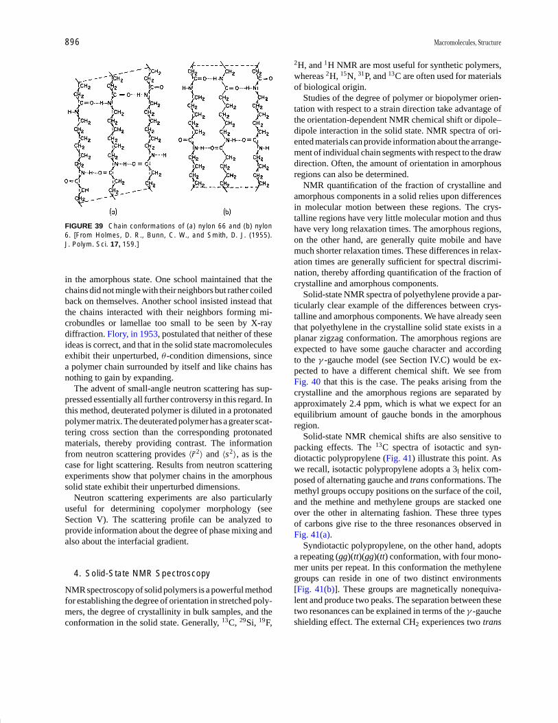
P1: GQT/LBX P2: GQT/MBQ QC: FYD Final Pages
Encyclopedia of Physical Science and Technology EN008C-602 July 25, 2001 20:31
896 Macromolecules, Structure
FIGURE 39 Chain conformations of (a) nylon 66 and (b) nylon6. [From Holmes, D. R., Bunn, C. W., and Smith, D. J. (1955).J. Polym. Sci. 17, 159.]
in the amorphous state. One school maintained that thechains did not mingle with their neighbors but rather coiledback on themselves. Another school insisted instead thatthe chains interacted with their neighbors forming mi-crobundles or lamellae too small to be seen by X-raydiffraction. Flory, in 1953, postulated that neither of theseideas is correct, and that in the solid state macromoleculesexhibit their unperturbed, θ -condition dimensions, sincea polymer chain surrounded by itself and like chains hasnothing to gain by expanding.
The advent of small-angle neutron scattering has sup-pressed essentially all further controversy in this regard. Inthis method, deuterated polymer is diluted in a protonatedpolymer matrix. The deuterated polymer has a greater scat-tering cross section than the corresponding protonatedmaterials, thereby providing contrast. The informationfrom neutron scattering provides 〈r2 〉 and 〈s2 〉, as is thecase for light scattering. Results from neutron scatteringexperiments show that polymer chains in the amorphoussolid state exhibit their unperturbed dimensions.
Neutron scattering experiments are also particularlyuseful for determining copolymer morphology (seeSection V). The scattering profile can be analyzed toprovide information about the degree of phase mixing andalso about the interfacial gradient.
4. Solid-State NMR Spectroscopy
NMR spectroscopy of solid polymers is a powerful methodfor establishing the degree of orientation in stretched poly-mers, the degree of crystallinity in bulk samples, and theconformation in the solid state. Generally, 13C, 29Si, 19F,
2H, and 1H NMR are most useful for synthetic polymers,whereas 2H, 15N, 31P, and 13C are often used for materialsof biological origin.
Studies of the degree of polymer or biopolymer orien-tation with respect to a strain direction take advantage ofthe orientation-dependent NMR chemical shift or dipole–dipole interaction in the solid state. NMR spectra of ori-ented materials can provide information about the arrange-ment of individual chain segments with respect to the drawdirection. Often, the amount of orientation in amorphousregions can also be determined.
NMR quantification of the fraction of crystalline andamorphous components in a solid relies upon differencesin molecular motion between these regions. The crys-talline regions have very little molecular motion and thushave very long relaxation times. The amorphous regions,on the other hand, are generally quite mobile and havemuch shorter relaxation times. These differences in relax-ation times are generally sufficient for spectral discrimi-nation, thereby affording quantification of the fraction ofcrystalline and amorphous components.
Solid-state NMR spectra of polyethylene provide a par-ticularly clear example of the differences between crys-talline and amorphous components. We have already seenthat polyethylene in the crystalline solid state exists in aplanar zigzag conformation. The amorphous regions areexpected to have some gauche character and accordingto the γ -gauche model (see Section IV.C) would be ex-pected to have a different chemical shift. We see fromFig. 40 that this is the case. The peaks arising from thecrystalline and the amorphous regions are separated byapproximately 2.4 ppm, which is what we expect for anequilibrium amount of gauche bonds in the amorphousregion.
Solid-state NMR chemical shifts are also sensitive topacking effects. The 13C spectra of isotactic and syn-diotactic polypropylene (Fig. 41) illustrate this point. Aswe recall, isotactic polypropylene adopts a 3l helix com-posed of alternating gauche and trans conformations. Themethyl groups occupy positions on the surface of the coil,and the methine and methylene groups are stacked oneover the other in alternating fashion. These three typesof carbons give rise to the three resonances observed inFig. 41(a).
Syndiotactic polypropylene, on the other hand, adoptsa repeating (gg)(tt)(gg)(tt) conformation, with four mono-mer units per repeat. In this conformation the methylenegroups can reside in one of two distinct environments[Fig. 41(b)]. These groups are magnetically nonequiva-lent and produce two peaks. The separation between thesetwo resonances can be explained in terms of the γ -gaucheshielding effect. The external CH2 experiences two trans

P1: GQT/LBX P2: GQT/MBQ QC: FYD Final Pages
Encyclopedia of Physical Science and Technology EN008C-602 July 25, 2001 20:31
Macromolecules, Structure 897
FIGURE 40 Solid-state 13C spectra of five polyethylene samples: (a) low-density polyethylene, (b)–(d) high-densitylinear polyethylene, and (e) ultraoriented polyethylene. [From Earl, W. L., and VanderHart, D. L. (1979). Macro-molecules 12, 762.]
FIGURE 41 Solid-state 13C NMR spectra of (a) isotactic and (b) syndiotactic polypropylene shown with the corre-sponding representations of their conformations. [From Bovey, F. A. (1982) “Chain Structure and Conformation ofMacromolecules,” Academic Press, New York.]
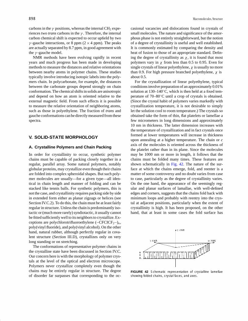
P1: GQT/LBX P2: GQT/MBQ QC: FYD Final Pages
Encyclopedia of Physical Science and Technology EN008C-602 July 25, 2001 20:31
898 Macromolecules, Structure
carbons in the γ positions, whereas the internal CH2 expe-riences two trans carbons in the γ . Therefore, the internalcarbon chemical shift is expected to occur upfield by twoγ -gauche interactions, or 8 ppm (2 × 4 ppm). The peaksare actually separated by 8.7 ppm, in good agreement withthe γ -gauche model.
NMR methods have been evolving rapidly in recentyears and much progress has been made in developingmethods to measure the distances and relative orientationsbetween nearby atoms in polymer chains. These studiestypically involve introducing isotopic labels into the poly-mers chain. In polycarbonate, for example, the distancesbetween the carbonate groups depend strongly on chainconformation. The chemical shifts in solids are anisotropicand depend on how an atom is oriented relative to theexternal magnetic field. From such effects it is possibleto measure the relative orientation of neighboring atoms,such as those in polyethylene. The fraction of trans andgauche conformations can be directly measured from thesespectra.
V. SOLID-STATE MORPHOLOGY
A. Crystalline Polymers and Chain Packing
In order for crystallinity to occur, synthetic polymerchains must be capable of packing closely together in aregular, parallel array. Some natural polymers, notablyglobular proteins, may crystallize even though their chainsare folded into complex spheroidal shapes. But such poly-mer molecules are usually—for a given type—all iden-tical in chain length and manner of folding and can bestacked like tennis balls. For synthetic polymers, this isnot the case, and crystallinity requires packing side by sidein extended form either as planar zigzags or helices (seeSection IV.C.2). To do this, the chain must be at least fairlyregular in structure. Unless the chain is predominantly iso-tactic or (much more rarely) syndiotactic, it usually cannotbe fitted sufficiently well to its neighbors to crystallize. Ex-ceptions are polychlorotrifluoroethylene ( CFCICF2 )n ,poly(vinyl fluoride), and poly(vinyl alcohol). On the otherhand, natural rubber, although perfectly regular in cova-lent structure (Section III.D), crystallizes only on verylong standing or on stretching.
The conformations of representative polymer chains inthe crystalline state have been discussed in Section IV.C.Our concern here is with the morphology of polymer crys-tals at the level of the optical and electron microscope.Polymers never crystallize completely even though thechains may be entirely regular in structure. The degreeof disorder far surpasses that corresponding to the oc-
casional vacancies and dislocations found in crystals ofsmall molecules. The nature and significance of the amor-phous phase is not entirely straightforward, but the notionof a degree of crystallinity is useful and well established.It is commonly estimated by comparing the density andheat of fusion to those of an appropriate standard. Defin-ing the degree of crystallinity as χ , it is found that mostpolymers vary in χ from less than 0.5 to 0.95. Even forsingle crystals of linear polyethylene, χ is usually no morethan 0.9. For high pressure branched polyethylene, χ isabout 0.5.
For the crystallization of linear polyethylene, typicalconditions involve preparation of an approximately 0.01%solution at 130–140◦C, which is then held at a fixed tem-perature of 70–80◦C until a crop of crystals is obtained.(Since the crystal habit of polymers varies markedly withcrystallization temperature, it is not desirable to simplylet the solution cool to room temperature.) The crystals soobtained take the form of thin, flat platelets or lamellae afew micrometers in long dimensions and approximately10 nm in thickness. The latter dimension increases withthe temperature of crystallization and in fact crystals onceformed at lower temperatures will increase in thicknessupon annealing at a higher temperature. The chain or caxis of the molecules is oriented across the thickness ofthe platelet rather than in its plane. Since the moleculesmay be 1000 nm or more in length, it follows that thechains must be folded many times. These features areshown schematically in Fig. 42. The nature of the sur-face at which the chains emerge, fold, and reenter is amatter of some controversy and no doubt varies from caseto case, particularly as the degree of crystallinity varies.On the one hand, the appearance of the seemingly reg-ular and planar surfaces of lamallae, with well-definededges and corners, suggests that the chains fold back withminimum loops and probably with reentry into the crys-tal at adjacent positions, particularly when the extent ofcrystallinity is high. It has been proposed, on the otherhand, that at least in some cases the fold surface has
FIGURE 42 Schematic representation of crystalline lamellaeshowing folded chains, crystal faces, and axes.
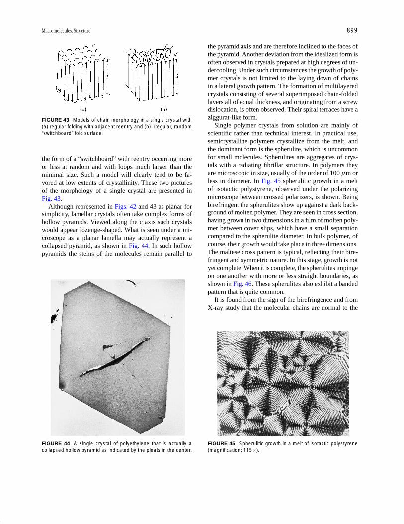
P1: GQT/LBX P2: GQT/MBQ QC: FYD Final Pages
Encyclopedia of Physical Science and Technology EN008C-602 July 25, 2001 20:31
Macromolecules, Structure 899
FIGURE 43 Models of chain morphology in a single crystal with(a) regular folding with adjacent reentry and (b) irregular, random“switchboard” fold surface.
the form of a “switchboard” with reentry occurring moreor less at random and with loops much larger than theminimal size. Such a model will clearly tend to be fa-vored at low extents of crystallinity. These two picturesof the morphology of a single crystal are presented inFig. 43.
Although represented in Figs. 42 and 43 as planar forsimplicity, lamellar crystals often take complex forms ofhollow pyramids. Viewed along the c axis such crystalswould appear lozenge-shaped. What is seen under a mi-croscope as a planar lamella may actually represent acollapsed pyramid, as shown in Fig. 44. In such hollowpyramids the stems of the molecules remain parallel to
FIGURE 44 A single crystal of polyethylene that is actually acollapsed hollow pyramid as indicated by the pleats in the center.
the pyramid axis and are therefore inclined to the faces ofthe pyramid. Another deviation from the idealized form isoften observed in crystals prepared at high degrees of un-dercooling. Under such circumstances the growth of poly-mer crystals is not limited to the laying down of chainsin a lateral growth pattern. The formation of multilayeredcrystals consisting of several superimposed chain-foldedlayers all of equal thickness, and originating from a screwdislocation, is often observed. Their spiral terraces have aziggurat-like form.
Single polymer crystals from solution are mainly ofscientific rather than technical interest. In practical use,semicrystalline polymers crystallize from the melt, andthe dominant form is the spherulite, which is uncommonfor small molecules. Spherulites are aggregates of crys-tals with a radiating fibrillar structure. In polymers theyare microscopic in size, usually of the order of 100 µm orless in diameter. In Fig. 45 spherulitic growth in a meltof isotactic polystyrene, observed under the polarizingmicroscope between crossed polarizers, is shown. Beingbirefringent the spherulites show up against a dark back-ground of molten polymer. They are seen in cross section,having grown in two dimensions in a film of molten poly-mer between cover slips, which have a small separationcompared to the spherulite diameter. In bulk polymer, ofcourse, their growth would take place in three dimensions.The maltese cross pattern is typical, reflecting their bire-fringent and symmetric nature. In this stage, growth is notyet complete. When it is complete, the spherulites impingeon one another with more or less straight boundaries, asshown in Fig. 46. These spherulites also exhibit a bandedpattern that is quite common.
It is found from the sign of the birefringence and fromX-ray study that the molecular chains are normal to the
FIGURE 45 Spherulitic growth in a melt of isotactic polystyrene(magnification: 115×).
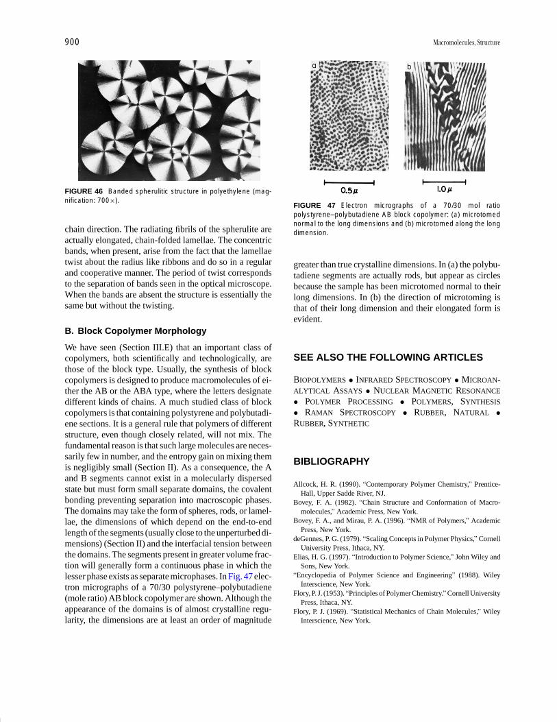
P1: GQT/LBX P2: GQT/MBQ QC: FYD Final Pages
Encyclopedia of Physical Science and Technology EN008C-602 July 25, 2001 20:31
900 Macromolecules, Structure
FIGURE 46 Banded spherulitic structure in polyethylene (mag-nification: 700×).
chain direction. The radiating fibrils of the spherulite areactually elongated, chain-folded lamellae. The concentricbands, when present, arise from the fact that the lamellaetwist about the radius like ribbons and do so in a regularand cooperative manner. The period of twist correspondsto the separation of bands seen in the optical microscope.When the bands are absent the structure is essentially thesame but without the twisting.
B. Block Copolymer Morphology
We have seen (Section III.E) that an important class ofcopolymers, both scientifically and technologically, arethose of the block type. Usually, the synthesis of blockcopolymers is designed to produce macromolecules of ei-ther the AB or the ABA type, where the letters designatedifferent kinds of chains. A much studied class of blockcopolymers is that containing polystyrene and polybutadi-ene sections. It is a general rule that polymers of differentstructure, even though closely related, will not mix. Thefundamental reason is that such large molecules are neces-sarily few in number, and the entropy gain on mixing themis negligibly small (Section II). As a consequence, the Aand B segments cannot exist in a molecularly dispersedstate but must form small separate domains, the covalentbonding preventing separation into macroscopic phases.The domains may take the form of spheres, rods, or lamel-lae, the dimensions of which depend on the end-to-endlength of the segments (usually close to the unperturbed di-mensions) (Section II) and the interfacial tension betweenthe domains. The segments present in greater volume frac-tion will generally form a continuous phase in which thelesser phase exists as separate microphases. In Fig. 47 elec-tron micrographs of a 70/30 polystyrene–polybutadiene(mole ratio) AB block copolymer are shown. Although theappearance of the domains is of almost crystalline regu-larity, the dimensions are at least an order of magnitude
FIGURE 47 Electron micrographs of a 70/30 mol ratiopolystyrene–polybutadiene AB block copolymer: (a) microtomednormal to the long dimensions and (b) microtomed along the longdimension.
greater than true crystalline dimensions. In (a) the polybu-tadiene segments are actually rods, but appear as circlesbecause the sample has been microtomed normal to theirlong dimensions. In (b) the direction of microtoming isthat of their long dimension and their elongated form isevident.
SEE ALSO THE FOLLOWING ARTICLES
BIOPOLYMERS • INFRARED SPECTROSCOPY • MICROAN-ALYTICAL ASSAYS • NUCLEAR MAGNETIC RESONANCE
• POLYMER PROCESSING • POLYMERS, SYNTHESIS
• RAMAN SPECTROSCOPY • RUBBER, NATURAL •RUBBER, SYNTHETIC
BIBLIOGRAPHY
Allcock, H. R. (1990). “Contemporary Polymer Chemistry,” Prentice-Hall, Upper Sadde River, NJ.
Bovey, F. A. (1982). “Chain Structure and Conformation of Macro-molecules,” Academic Press, New York.
Bovey, F. A., and Mirau, P. A. (1996). “NMR of Polymers,” AcademicPress, New York.
deGennes, P. G. (1979). “Scaling Concepts in Polymer Physics,” CornellUniversity Press, Ithaca, NY.
Elias, H. G. (1997). “Introduction to Polymer Science,” John Wiley andSons, New York.
“Encyclopedia of Polymer Science and Engineering” (1988). WileyInterscience, New York.
Flory, P. J. (1953). “Principles of Polymer Chemistry.” Cornell UniversityPress, Ithaca, NY.
Flory, P. J. (1969). “Statistical Mechanics of Chain Molecules,” WileyInterscience, New York.

P1: GQT/LBX P2: GQT/MBQ QC: FYD Final Pages
Encyclopedia of Physical Science and Technology EN008C-602 July 25, 2001 20:31
Macromolecules, Structure 901
Hunt, B. J., and James, M. I. (1993). “Polymer Characterization,” BlackieAcademic and Professional, Glasgow.
Koenig, J. L. (1990). “Chemical Microstructure of Polymer Chains,”Kreiger, Melborne, FL.
Odian, G. (1970). “Principles of Polymerization,” McGraw-Hill,
New York.Painter, P. C., and Coleman, M. M. (1997). “Fundamentals of Polymer
Science: An Introductory Text,” Technomic Publishing, Lancaster, PA.Salamone, J. C. (1998). “Concise Polymeric Materials Encyclopedia,”
CRC Press, Boca Raton, FL.
P1: GOX/LBD P2: GLQ Final Pages Qu: 00, 00, 00, 00
Encyclopedia of Physical Science and Technology EN012K-587 July 26, 2001 10:35
Plastics EngineeringR. J. CrawfordUniversity of Auckland
I. General Types of PlasticsII. Design Considerations
III. Material and Process SelectionIV. Successful Engineering Applications for Plastics
GLOSSARY
Composite A material that is a combination of two ormore constituents, each of which retains its own iden-tity. In the context of this article, the constituentsare fibers within a thermoplastic or thermosettingmatrix.
Creep The time-dependent change in the dimensions ofa plastic under the action of a static load.
Cross-linking The formation of an infusible structure bythe joining together of individual molecular chains intoa three-dimensional network.
Ductility The ability of a material to deform plasticallybefore fracture.
Elastomers Plastics that exhibit the large deformation/elastic recovery characteristics of rubbery materials.
Engineering plastics A general name for plastics suit-able for use in load-bearing applications.
Fatigue The failure of a material as a result of the repeatedapplication of a fluctuating stress or strain.
Fiber A general term for a filament of material that has alength at least 100 times its diameter.
Heat-deflection temperature The temperature at whicha standard test piece deflects by a specified amountwhen subjected to a specified force.
Modulus The ratio of stress to strain in a material, at aspecified level of strain.
Speciality plastics Materials with special characteris-tics usually in regard to high-temperature proper-ties.
Stiffness A measure of the ratio of load to deformation;there is usually a direct correlation with modulus,but modulus is an inherent material property whereasstiffness depends on the shape of the material beingstressed.
Thermoplastic A material capable of being repeatedlysoftened by heat and hardened by cooling.
Thermoset A plastic that when subjected to heat (or achemical process) changes into an infusible, insolublematerial.
Viscoelasticity A property of a material whereby it ex-hibits the combined effects of viscous and elastic be-havior.
PLASTICS are now well established in all branches of en-gineering as cost-effective, high-performance materials.A major attraction of plastics is that when one takes intoaccount the overall costs of conversion from raw mate-rial to final product, plastics almost always come out best.
457

P1: GOX/LBD P2: GLQ Final Pages
Encyclopedia of Physical Science and Technology EN012K-587 July 26, 2001 10:35
458 Plastics Engineering
In addition, although the absolute mechanical propertyvalues of plastics are less than those for metals, the lowdensity of plastics means that their specific propertiescompare very favorably with other materials. When oneadds on the other attractive properties of plastics suchas chemical and environmental resistance, toughness, andresilience, and in particular, ease of processing into com-plex shapes, it is clear that the engineering applicationsfor plastics will continue to increase.
I. GENERAL TYPES OF PLASTICS
The most characteristic feature of the structure of plasticsis that they consist of relatively long molecules. Thesemolecules are usually referred to as “chain-like” becauseduring the manufacture of the plastic a large number ofsmall units have been linked together. In most cases themolecular chain has a carbon backbone, and it is the vary-ing nature of the side groups off the backbone that gives thedifferent types of plastics their individual characteristics.
The forces between molecular chains are relativelyweak, so that when a plastic is heated the thermal energy iscapable of moving the chains apart. In this state the struc-ture has a random configuration, and the plastic can easilyflow into a mold or through a die to take any desired shape.When heat is extracted from the plastic it is transformedfrom a melt to a solid and retains its new shape.
If the side groups on the molecular chain are simple,it is possible for the structure of the plastic to attain avery ordered structure. If this occurs the plastic is said tobe crystalline or, perhaps more accurately, semicrystallinesince no plastic is capable of becoming totally crystalline.The degree of crystallinity can be controlled, to some ex-tent, during molding operations, and it is important thatthe molder is aware of the effects on properties that can beproduced. Crystallinity in a plastic improves some of itsmechanical properties (such as modulus) but shrinkage isgreater, and in a particular plastic the toughness is reducedas the degree of crystallinity increases. Chemists can alsotake steps to control crystallinity; this can be used as onemethod to obtain, for example, high-temperature plastics.
Some plastics have a molecular structure that does notpermit any type of crystalline structure. These plasticsare referred to as amorphous in that they have a randommolecular structure in both the molten and the solid states.Amorphous plastics are always capable of being transpar-ent, although the addition of fillers and pigments resultsin their being available in a wide range of opaque col-ors. Semicrystalline plastics contain both amorphous andcrystalline regions in their structure. The way that theseregions co-exist has a major effect on the properties of theplastic. Semicrystalline plastics are naturally opaque, but
if crystallization is prevented (by, for example, rapid cool-ing from the melt) transparent moldings can be produced.The classic example of this is the manufacture of bottlesfrom polyethylene terephthalate (PET).
The semicrystalline and amorphous types of plastic re-ferred to above are more generally known as thermoplas-tics. This is because they are capable of going throughan almost indefinite cycle of being softened by heat andbecoming solid again when the heat is removed. The mostdistinguishing feature of this type of plastic is that thepolymer chains remain linear and separate after molding.In contrast to this it is possible to have thermosetting plas-tics, which can be softened only once to take up the shapeof the mold. Once these materials have solidified theycannot be softened by the application of heat or by anyother method. When heat and pressure are applied to athermosetting plastic during the initial molding process,the structure undergoes a chemical reaction that locks itinto a three-dimensional network. This is called cross-linking; it is initiated by heat, chemical agents, irradiation,or a combination of these. As a result of this cross-linking,thermosets have an obvious advantage in that they will notsoften in high-temperature environments. Thermosets alsohave improved resistance to chemical attack, stress crack-ing, and creep. However, they are not so easy to moldas the thermoplastics, and generally they cannot offer thesame level of toughness.
Examples of thermoplastics are polypropylene, poly-carbonate, polyvinyl chloride, ABS, polystyrene, acetal,and nylon (polyamide). Examples of thermosets are epox-ies, phenolics, ureas, and melamines. Polyesters andpolyurethanes can be available as both thermoplastic andthermosetting materials. It should be noted that somethermoplastics, such as polyethylene, are now commer-cially available in cross-linkable grades, so the distinctionbetween a thermoplastic material and a thermosetting ma-terial is becoming less clear-cut.
The types of plastics used successfully in engineeringapplications cover the full range of thermoplastics andthermosets that are available. This means that the designerhas access to materials ranging from polyethylene topolyetheretherketone (PEEK). In the former case theelastic modulus is low (300 to 400 MN/m2), but withproper design it may be used in critical, demandingapplications—for example, nationwide pressurized gas-distribution pipes. The modulus of polyethylene can alsobe increased by a factor of 100 if its structure is highlyoriented by stretching the material under controlledconditions in the solid state. In the case of PEEK, it isan expensive material that possesses unique properties.When combined with carbon fibers, it provides a materialthat is stronger and has a higher modulus than many metals(see Table I).
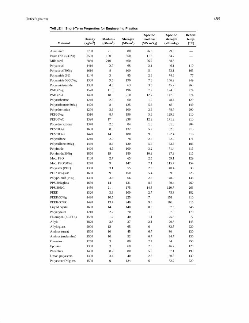
P1: GOX/LBD P2: GLQ Final Pages
Encyclopedia of Physical Science and Technology EN012K-587 July 26, 2001 10:35
Plastics Engineering 459
TABLE I Short-Term Properties for Engineering Plastics
Specific Specific Deflect.Density Modulus Strength modulus strength temp.
Material (kg/m3) (GN/m2) (MN/m2) (MN m/kg) (kN m/kg) (◦C)
Aluminum 2700 71 80 26.3 29.6 —
Brass (70Cu/30Zn) 8500 100 550 11.8 64.7 —
Mild steel 7860 210 460 26.7 58.5 —
Polyacetal 1410 2.9 65 2.1 46.1 110
Polyacetal/30%g 1610 8 100 5 62.1 163
Polyamide (66) 1140 3 85 2.6 74.6 77
Polyamide 66/30%g 1300 9.5 190 7.3 146.2 249
Polyamide-imide 1380 4.6 63 3.3 45.7 260
PAI/30%g 1570 11.3 196 7.2 124.8 274
PAI/30%C 1420 18 210 12.7 147.9 274
Polycarbonate 1240 2.3 60 1.9 48.4 129
Polycarbonate/30%g 1420 8 125 5.6 88 149
Polyetherimide 1270 3.3 100 2.6 78.7 200
PEI/30%g 1510 8.7 196 5.8 129.8 210
PEI/30%C 1390 17 238 12.2 171.2 210
Polyethersulfone 1370 2.5 84 1.8 61.3 204
PES/30%g 1600 8.3 132 5.2 82.5 213
PES/30%C 1470 14 180 9.5 122.4 216
Polysulfone 1240 2.9 78 2.3 62.9 171
Polysulfone/30%g 1450 8.3 120 5.7 82.8 185
Polyimide 1400 4.5 100 3.2 71.4 315
Polyimide/30%g 1850 19 180 10.3 97.3 315
Mod. PPO 1100 2.7 65 2.5 59.1 129
Mod. PPO/30%g 1270 9 147 7.1 115.7 154
Polyester (PET) 1360 3.1 55 2.3 40.4 38
PET/30%glass 1680 9 150 5.4 89.3 225
Polyph. sulf (PPS) 1350 3.8 66 2.8 48.9 138
PPS/30%glass 1650 14 131 8.5 79.4 260
PPS/30%C 1450 21 175 14.5 120.7 263
PEEK 1320 3.6 100 2.7 75.8 182
PEEK/30%g 1490 10.5 225 7 151 310
PEEK/30%C 1420 13.7 240 9.6 169 315
Liquid crystal 1600 14 140 8.8 87.5 346
Polyarylates 1210 2.2 70 1.8 57.9 170
Fluoropol. (ECTFE) 1580 1.7 40 1.1 25.3 77
Allyls 1820 3.8 37 2.1 20.3 145
Allyls/glass 2000 12 65 6 32.5 220
Aminos (urea) 1500 10 45 6.7 30 130
Aminos (melamine) 1500 10 52 6.7 34.7 130
Cyanates 1250 3 80 2.4 64 250
Epoxies 1300 3 60 2.3 46.2 120
Phenolics 1400 8.2 80 5.9 57.1 190
Unsat. polyesters 1300 3.4 40 2.6 30.8 130
Polyester/40%glass 1500 9 124 6 82.7 220

P1: GOX/LBD P2: GLQ Final Pages
Encyclopedia of Physical Science and Technology EN012K-587 July 26, 2001 10:35
460 Plastics Engineering
Traditionally, plastics have been divided into a numberof specific categories. Although these tend to be some-what imprecise in that many plastics can belong to severalcategories, the terminology does help to give a broad in-dication of the potential uses of individual plastics.
1. Engineering plastics: Although most plastics can beused in engineering applications, one group has been dis-tinguished by the description engineering plastics. Theseare polyamides, polycarbonates, polyacetals, modifiedpolyphenylene ethers, and thermoplastic polyesters. Theuse of the term engineering plastic probably arose whenit was established that these materials could be used assuccessful substitutes for metals in light engineering ap-plications (for example, gear wheels, pulleys, etc.).
2. Speciality plastics: Other high-performance plas-tics, such as polysulphone and polyphenylene sulphide,are sometimes included in the list of engineering plastics,but the consumption of these materials is relatively smallbecause economic factors restrict them for the more de-manding types of application. Hence, these materials,along with exciting recent arrivals such as polyimides,fluoropolymers, polyetherketones, and polyarylates, tendto be more accurately described as speciality plastics. Aparticular feature of this type of plastic is the ability tobe used continuously at service temperatures up to 300◦Cin circumstances where some metals cannot even be con-sidered candidate materials. Typical properties of thesematerials are shown in Table I.
3. Elastomers (thermoplastic rubbers): Conventionalvulcanized rubbers possess a range of very desirableproperties, such as resilience and flexibility, over a widetemperature range and resistance to oils, greases, ozone,etc. However, they require careful, relatively slow process-ing, and it is not possible to reuse any waste material. Toovercome the latter disadvantages, in recent years a rangeof thermoplastic rubbery materials has been developed.These exhibit the familiar feel and performance of rubbersbut have the ease of manufacture associated with thermo-plastics. There are several basic types of thermoplasticrubber (TPR). These differ in the way they impart rubber-like properties to the thermoplastic. In the polyurethane,styrenic, and polyester TPRs the chemists have graftedthermoplastic molecules on the rubber molecules. In theolefinic TPR there is a polypropylene matrix with finerubber particles embedded in it to provide the elastomericproperties. Other types of TPR are based on polyamideand are essentially alloys. New advancements in poly-mer chemistry have created other families of elastomers—plastomers, metallocene-based EPDM alloys, styrene-ethylene block copolymers, and other blends and alloys.
4. Polymer alloys: Blends and alloys have become animportant part of the plastics materials scene in recent
years. The concept of combining different materialsto bring together their desirable attributes into onematerial has been utilized with metals for centuries,but its exploitation has been slow with plastics. ABS(acrylonitrile-butadiene-styrene) was one of the firstcommercially available plastic alloys but its successcould not be generally extended to other materials dueto the inherent incompatibility of most plastics. A recentrevival of interest in polymer alloys has been caused bytwo factors. The first is the result of breakthroughs in theblending technology, so that some very interesting andexciting combinations have become possible. The secondfactor is that some lucrative market sectors (for example,the automotive industry) are demanding property specifi-cations not available in a single plastic. As a result, thereis an ever increasing range of commercially availablealloys, and the material suppliers are prepared to listen torequests for combinations not yet available. Some of themost interesting and successful alloys are polyphenyleneoxide/polystyrene (modified PPO), polycarbonate/ABS,polyamide/polypropylene, polyamide/polyphenyleneether, ASA/polycarbonate, and PBT/polycarbonate.
5. Structural foam: Many plastics can be foamed bythe introduction of a blowing agent so that after mold-ing the product consists of a cellular foam core and a solidskin. This type of structure is very efficient in terms of stiff-ness per unit weight. The foam effect is normally achievedby preblending the plastic granules with a heat-activatedblowing agent. Polycarbonate, polypropylene, and modi-fied PPO are popular materials for foam molding.
6. Liquid-crystal polymer (LCP): These polymers ar-rived on the materials scene in the mid-1980s. Theyhave an exciting new type of structure that is highly or-dered, even in the molten state. The structure has beenlikened to a stack of uncooked spaghetti: if subjected tostress the stiff rods can slide past one another, but thesame ordered orientation is retained. It is this retentionof structural order in LCPs that gives them exceptionalproperties. They have outstanding dimensional stability,high strength, stiffness, toughness, and excellent chemi-cal resistance. They also have very good high-temperatureperformance (up to 300◦C), and they are easy to process.
7. Oriented polymers: When the chain-like structureof polymers is drawn out so that the chains become highlyoriented, it is possible to achieve very high strength andstiffness values. For example, the modulus of polyethy-lene can readily be increased from under 1 GN/m2 toabout 70 GN/m2. Hot stretching of the plastic can bringabout some improvement in properties, but the maximumbenefit is gained by cold drawing. In addition to me-chanical properties, it has been shown that conductivity,diffusion/solubility, and piezoelectric properties are alsoenhanced, and this opens the door to new application areas.

P1: GOX/LBD P2: GLQ Final Pages
Encyclopedia of Physical Science and Technology EN012K-587 July 26, 2001 10:35
Plastics Engineering 461
Materials that have shown themselves to be amenable tohigh degrees of structural orientation include polyethy-lene, PVC, and PMMA.
8. Composites: Although unreinforced plastics can beused in engineering applications, it is only when fiberreinforcement is added that they become serious chal-lengers for metals in the more demanding applications.Both thermoplastics and thermosets can benefit from fiberreinforcement. In the past these two types of compositestended to develop in separate ways and targeted differentmarket sectors. However, in recent years the reinforcementtechnologies have moved closer together and now they of-ten compete directly for the same applications. When fiberreinforcement was first identified as a means of obtainingvery significant improvements in the mechanical proper-ties of plastics, it was continuous-fiber reinforcement thatattracted most attention. As the very large surface area ofthe continuous fibers needed to be completely wetted, itwas necessary to use the low-molecular-weight resins thatcould be subsequently polymerized when the structure hadbeen shaped. Hence, thermosetting resins dominated thecontinuous-fiber, high-performance sector, but the manu-facturing processes were slow. In contrast, the thermoplas-tic industry concentrated on their fast production methods,such as injection molding, but were obliged to accept lowerproperty enhancement through the use of short fibers. Inrecent years this situation has changed in that the ther-mosetting industry is prepared to sacrifice properties, thatis, use shorter fibers to speed up production rates. Simi-larly the thermoplastic industry has devised ways of wet-ting continuous fibers with thermoplastic resins to get intothe more lucrative high-performance application areas (forexample, aerospace). The main advantages that thermo-plastics have over thermosets are that they offer bettertoughness (damage tolerance) and they have better waterresistance. It is evident that for thermosets it is possible toimprove either one of these characteristics to acceptablestandards but not both at the same time.
The continuous-fiber reinforced thermoplastics are nor-mally available as a flat sheet containing the reinforce-ment. This is heated and shaped between matched halvesof a mold to produce the desired shape. Also available inthe thermoplastic sector are long (as opposed to continu-ous) fibers for reinforcement. The raw material is availableas injection-moldable pellets containing wetted fibers thatare the full length of the pellet, typically 10 mm. Normally,short fibers have lengths in the range of 0.75 to 0.5 mmso that the long fiber-reinforced thermoplastics have verysignificantly improved properties while retaining the easy,fast processing associated with injection molding.
The type of fiber used in plastics has a major effect onthe properties and economics of a product. Glass fibers are
generally the least expensive, and they improve the creepresistance, thermal conductivity, and high-temperature ca-pability of the plastic at short and long times. The extentof the improvement depends on the efficiency of the bondbetween the fiber and the base resin. This is where aramidfibers have had difficulty in the past. Although they of-fer a better property enhancement than glass, the highsurface energy of the lightweight fibers makes wettingthe fibers and dispersion of the base resin difficult. Theseproblems have to a large extent been overcome by the de-velopment of special proprietary sizing/coupling systems.Characteristic features of aramid-reinforced plastics arelow warpage and thermal expansion and uniform proper-ties in all directions.
Carbon fibers offer the best improvements in strength,stiffness, and thermal conductivity, albeit at a price. Thereare also very significant increases in the heat-deflectiontemperature, creep resistance, and fatigue endurance.Carbon fibers also offer the ability to dissipate static elec-tric charges very effectively; this is becoming a crucial fea-ture in many new application areas for plastics. The resis-tivity of most plastics is in the region of 1012–1016 � cm,which means that they are excellent electrical insulators.However, there is a developing market in areas such aselectronic component housings, EMI shielding, and bat-tery construction where some degree of electrical conduc-tivity in plastics would be desirable. The simplest way toachieve this is to load the plastic with a conductive fillersuch as metal or carbon. The developing technology is todevise structures in plastics that are intrinsically conduc-tive, and some exciting advances have already been madein this field.
Natural fibers, such as jute, sisal, flax and hemp, arealso used in plastics. There are attractive because theyare low-cost, low-density materials offering good spe-cific properties and they are friendly to the environment.However, there are also problems to be overcome. Thepoor moisture resistance of natural fibers and their in-compatibility with the matrix resin are problems thatattract a lot of research activity in some parts of theworld.
An exciting development area in plastics is nanocom-posites. This involves the addition of 2–5% of nanometer-size particles into a plastic to enhance fire resistance,improve mechanical properties, reduce thermal conduc-tivity, and reduce permeability. The low addition levels ofthese very fine particles does not alter density of trans-parency. The automotive industry has been one of the firstto utilize these materials for under-the-hood components.The original nanocomposites were produced by addingthe small particles at the reactor stage but recent successhas been achieved by compounding them into the plasticusing and extruder.
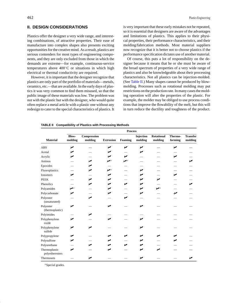
P1: GOX/LBD P2: GLQ Final Pages
Encyclopedia of Physical Science and Technology EN012K-587 July 26, 2001 10:35
462 Plastics Engineering
II. DESIGN CONSIDERATIONS
Plastics offer the designer a very wide range, and interest-ing combinations, of attractive properties. Their ease ofmanufacture into complex shapes also presents excitingopportunities for the creative mind. As a result, plastics areserious contenders for most types of engineering compo-nents, and they are only excluded from those in which thedemands are extreme—for example, continuous-servicetemperatures above 400◦C or situations in which highelectrical or thermal conductivity are required.
However, it is important that the designer recognize thatplastics are only part of the portfolio of materials—metals,ceramics, etc.—that are available. In the early days of plas-tics it was very common to find them misused, so that thepublic image of these materials was low. The problem wasnot with the plastic but with the designer, who would quiteoften replace a metal article with a plastic one without anyredesign to cater to the special characteristics of plastics. It
TABLE II Compatibility of Plastics with Processing Methods
Process
Blow- Compression Injection Rotational Thermo- TransferMaterial molding molding Extrusion Foaming molding molding forming molding
ABS — — —
Acetal — — — — —
Acrylic — — — —
Aminos — a a — — —
Epoxides — — — — — — —
Fluoroplastics — a — — — —
Ionomers — — — —
PEEK — — — —
Phenolics — — —
Polyamides a — — a — —
Polycarbonate — — — - —
Polyester — — — — — —(unsaturated)
Polyester — — — — —(thermoplastic)
Polyimides — — — — — — —
Polyphenylene — — — — —oxide
Polyphenylene — — — — —sulfide
Polypropylene — —
Polysulfone — — — —
Polyurethane — — — —
Thermoplastic — — — —polyetheresters
Thermosets — — — — —
aSpecial grades.
is very important that these early mistakes not be repeated,so it is essential that designers are aware of the advantagesand limitations of plastics. This applies to their physi-cal properties, their performance characteristics, and theirmolding/fabrication methods. Most material suppliersnow recognize that it is better not to choose plastics if theperformance specification dictates use of another material.
Of course, this puts a lot of responsibility on the de-signer because it means that he or she must be aware ofthe broad spectrum of properties of a very wide range ofplastics and also be knowledgeable about their processingcharacteristics. Not all plastics can be injection-molded.(See Table II.) Many shapes cannot be produced by blow-molding. Processes such as rotational molding may putrestrictions on the production rate. In many cases the mold-ing operation will alter the properties of the plastic. Forexample, the molder may be obliged to use process condi-tions that improve the flowability of the melt, but this willin turn reduce the ductility and toughness of the product.

P1: GOX/LBD P2: GLQ Final Pages
Encyclopedia of Physical Science and Technology EN012K-587 July 26, 2001 10:35
Plastics Engineering 463
A good designer must be aware of such factors. This isparticularly true in our modern society, which has cometo expect high performance and regular design upgrades.
The task of choosing the correct plastic may appeardaunting, but to most designers plastics offer an excitingchallenge. The design process is not difficult but it requiresa clear, logical, and open-minded approach. The first stepmust always be a precise statement of the design speci-fication. This must define (1) the structural demands onthe material, (2) the environmental factors relevant to theproduct, (3) the special codes of approval that may apply(e.g., food contact or aircraft authorities), (4) the appear-ance required (transparent, colored, decorated, etc.), and(5) the number of articles required.
On the basis of this type of information, it is possibleto draw up a short list of materials. Many materials sup-pliers and a number of commercial organizations providecomputerized databases that assist greatly at the materialselection stage. The internet is also an excellent source ofdata and information on plastics.
Using these data, it is necessary to finalize the shapeand then identify the most appropriate molding method.These must be considered together because each moldingmethod places limitations on shape (e.g., wall-thicknessdistribution, undercuts, etc.). At the detailed mold designstage, when one is considering corner radii, draft angles,positioning of vents, shrinkage, etc., it is usual to seekadvice from both the molder and the moldmaker becauseeach will have a unique contribution to make. By the timethat metal for the mold is being cut it is extremely im-portant to have the selection of a plastic made becausethe shrinkage, dimensional tolerances, etc., that must beallowed for will be different for each plastic. Some of thegeneral characteristics of thermoplastics and thermosetsare indicated below.
A. Thermoplastics
1. ABS (acrylonitrile-butadiene-styrene): Easily mol-ded, tough, hard, plastic with a relatively high modulus.Good dimensional stability with low water absorption.Good wear resistance and some grades can be electro-plated.
2. Acetal: Available as a homopolymer or copolymer.Strong engineering plastic with a good modulus, low wa-ter absorption, and excellent dimensional stability. Highresistance to wear and chemicals and excellent propertyretention in hot water. Low tendency to stress-crack.
3. Acrylic: Hard, glossy plastic with high optical clar-ity and excellent resistance to outdoor weathering.
4. Cellulosics: Family of tough, hard plastics com-prising cellulose acetate, butyrate, propionate, and ethylcellulose. Dimensional stability is generally fair. Moisture
and chemical resistance is variable depending on thegrades.
5. Fluoroplastics: Large family of low-strength, high-cost plastics that have a number of distinguishing features.In particular, they offer excellent dielectric properties,high-temperature stability, and chemical resistance. PTFEhas a coefficient of friction that is one of the lowest forany material. Other plastics in this group are FEP, PFA,CTFE, ECTFE, ETFE, and PVDF.
6. Ionomers: Tough, tear-resistant plastics with ex-cellent outdoor weathering resistance. Can be transparentand have good chemical resistance.
7. Polyamide: Engineering plastic with high tough-ness and wear resistance. Coefficient of friction is low andchemical resistance is excellent. Water absorption is high,so dimensional stability tends to be low.
8. Polyamide-imide: A high-cost amorphous plasticthat offers high strength, high-temperature performance.
9. Polyarylates: Family of tough, heat-resistant plas-tics with excellent outdoor weathering resistance. Verylow inherent flammability and high resistance to creepand warpage.
10. Polyaryletherketones: Strong, heat-resistant crys-talline plastics capable of continuous service at 250◦C.Excellent chemical and wear resistance. Family comprisespolyetheretherketone (PEEK), polyetherketone (PEK),and polyetherketoneketone (PEKK).
11. Polycarbonate: An amorphous plastic with out-standing toughness. Excellent outdoor weathering resis-tance and good creep resistance. Susceptible to chemicalattack and stress cracking.
12. Polyester: Polybutylene terephthalate (PBT) andpolyethylene terephthalate (PET). Characterized by toug-hness with excellent dimensional stability. Good chemicalresistance (except to strong acids and bases) and low wa-ter absorption. Generally notch-sensitive and not suitablefor outdoor use. PET is capable of high optical clarity ifprevented from crystallizing.
13. Polyetherimide: A strong, tough amorphous plas-tic suitable for use at high temperatures. Easily processed,with good dimensional stability and broad chemical resis-tance.
14. Polyethylene: Basically a commodity plastic butcapable of performing in load-bearing applications ifproperly designed. Easily processed, tough, inexpensiveplastic with excellent chemical resistance. Medium andhigh density grades are stronger and harder.
15. Polyimide: A tough plastic with good wear re-sistance and low coefficient of thermal expansion. Out-standing high-temperature properties but expensive andnot easy to process.
16. Polyphenylene ether: The homopolymer is fre-quently referred to as polyphenylene oxide (PPO). Rigid,
P1: GOX/LBD P2: GLQ Final Pages
Encyclopedia of Physical Science and Technology EN012K-587 July 26, 2001 10:35
464 Plastics Engineering
amorphous plastics offering a broad working-temperaturerange. Very low water absorption and so excellent dimen-sional stability. Very amenable to blending with other plas-tics to produce alloys.
17. Polyphenylene sulfide: Good strength characteris-tics from low to high temperatures. Inert to most chemicalsand inherently flame retardant.
18. Polypropylene: Part of the same generic group aspolyethylene. Low-density, tough plastic (above roomtemperature) and very easy to mold. Outstanding fatigueresistance and stress-crack resistance.
19. Polysulfone: A clear, rigid, tough plastic capableof continuous use at 160◦C. Excellent chemical resistancebut notch-sensitive and expensive. Polyether sulfone isone of the most commercially successful members of thepolysulfone family.
20. Polyurethane: Versatile material available in a widerange of forms. Very tough, with high abrasion and chem-ical resistance. Popular foaming material (rigid or flexiblefoams). Susceptible to ultraviolet attack. Also available asa thermoset.
21. Polyvinyl chloride: Wide range of formulationsfrom hard–rigid to soft–flexible material. Hard and toughwith excellent electrical insulation properties. Goodoutdoor weatherability and resistance to moisture andchemicals.
B. Thermosets
1. Alkyd: Easy, fast-molding material with no volatileby-products. Excellent electrical insulation with good heatresistance and low moisture absorption. Developed in the1930s; one of the earliest applications was for automotivedistributor caps.
2. Allyl: Excellent all-round electrical properties evenunder long-term heat and moisture. Also good resistanceto chemicals even at high temperatures.
3. Aminos: Urea and melamine formaldehyde are themost common forms. Very easily colored. Urea is less exp-ensive and molds more easily but melamine has higherhardness and better chip resistance and is more resistantto temperature and chemicals.
4. Bismaleimide (BMI): Excellent high-temperatureperformance but, like most thermosetting materials, itlacks toughness.
5. Cyanates: Tough materials with excellent adhesivepeel strength. Low dielectric loss and moisture absorption.Good dimensional stability.
6. Epoxies: Excellent combination of mechanicalstrength, electrical resistance, and adhesion to mostmaterials. Low mold shrinkage, and some formulationscure without heat or pressure. Most grades are relativelybrittle.
7. Melamine formaldehyde: The hardest of all plas-tics, this material is excaellent for food contact applica-tions and is fire resistant. Requires higher pressure thanphenolics to mold but its color properties are superior tothose of the polyesters.
8. Phenolics: General purpose, cost-effective resins.One of the first synthetic plastics; developed by Leo H.Baekeland in the early 1900s. Color limited to black orbrown. Easily molded into complex shapes with good di-mensional stability. Good creep resistance and very hardsurface.
9. Polyesters: Unlimited colors and also availabletransparent. Easy to mold but shrinkage is high. Very popu-lar resin for use with glass fibers; product is often referredto as fiberglass. Also form basis for the popular (easilymolded) bulk molding compound (BMC) and sheet mold-ing compound (SMC).
10. Polyimides: These materials have a low dielectricconstant and a high dielectric strength. Their chemicalresistance and creep resistance are both excellent. Alsoavailable as a thermoplastic.
11. Polyurethane: Wide range of formulations. Thegreater the degree of cross-linking, the greater thehardness. Excellent toughness, good traction properties,and resistance to wear make it ideal for skate wheels andshoe heels. Also available as a thermoplastic.
12. Silicones: Can be available as elastomeric or rigidmaterials. They are very inert and can be used over abroad temperature range. Popular as gaskets, sealing rings,and O-rings. They have good weatherability and excellentelectrical properties.
13. Urea formaldehyde: Can be available in a rangeof colors. Good surface hardness and electrical propertiesbut relatively poor heat resistance.
C. General Behavior Characteristicsof Engineering Plastics
The successful design of plastic articles requires a broaderrange of knowledge of materials behavior than would bethe case for designing a metal product. This is becausefactors such as time, temperature, environment, etc. arevariables that must be considered in almost all cases forplastics, whereas these are only relevant in extreme casesfor metals. The simplest illustration of this is the designof a product to be subjected to a static load at room tem-perature. If the product is made from metal and it is ableto withstand the applied load in the short term, one canhave reasonable confidence that there will be no prob-lems in the long term. However, with plastics the modu-lus (related to the stiffness) of the material will decreasewith time, so the ability to withstand the applied load inthe short term should not lead one to assume that it will
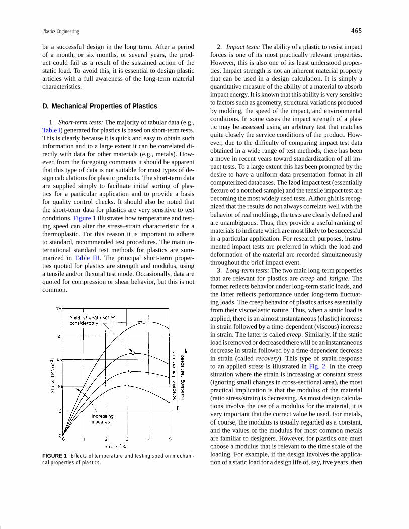
P1: GOX/LBD P2: GLQ Final Pages
Encyclopedia of Physical Science and Technology EN012K-587 July 26, 2001 10:35
Plastics Engineering 465
be a successful design in the long term. After a periodof a month, or six months, or several years, the prod-uct could fail as a result of the sustained action of thestatic load. To avoid this, it is essential to design plasticarticles with a full awareness of the long-term materialcharacteristics.
D. Mechanical Properties of Plastics
1. Short-term tests: The majority of tabular data (e.g.,Table I) generated for plastics is based on short-term tests.This is clearly because it is quick and easy to obtain suchinformation and to a large extent it can be correlated di-rectly with data for other materials (e.g., metals). How-ever, from the foregoing comments it should be apparentthat this type of data is not suitable for most types of de-sign calculations for plastic products. The short-term dataare supplied simply to facilitate initial sorting of plas-tics for a particular application and to provide a basisfor quality control checks. It should also be noted thatthe short-term data for plastics are very sensitive to testconditions. Figure 1 illustrates how temperature and test-ing speed can alter the stress–strain characteristic for athermoplastic. For this reason it is important to adhereto standard, recommended test procedures. The main in-ternational standard test methods for plastics are sum-marized in Table III. The principal short-term proper-ties quoted for plastics are strength and modulus, usinga tensile and/or flexural test mode. Occasionally, data arequoted for compression or shear behavior, but this is notcommon.
FIGURE 1 Effects of temperature and testing sped on mechani-cal properties of plastics.
2. Impact tests: The ability of a plastic to resist impactforces is one of its most practically relevant properties.However, this is also one of its least understood proper-ties. Impact strength is not an inherent material propertythat can be used in a design calculation. It is simply aquantitative measure of the ability of a material to absorbimpact energy. It is known that this ability is very sensitiveto factors such as geometry, structural variations producedby molding, the speed of the impact, and environmentalconditions. In some cases the impact strength of a plas-tic may be assessed using an arbitrary test that matchesquite closely the service conditions of the product. How-ever, due to the difficulty of comparing impact test dataobtained in a wide range of test methods, there has beena move in recent years toward standardization of all im-pact tests. To a large extent this has been prompted by thedesire to have a uniform data presentation format in allcomputerized databases. The Izod impact test (essentiallyflexure of a notched sample) and the tensile impact test arebecoming the most widely used tests. Although it is recog-nized that the results do not always correlate well with thebehavior of real moldings, the tests are clearly defined andare unambiguous. Thus, they provide a useful ranking ofmaterials to indicate which are most likely to be successfulin a particular application. For research purposes, instru-mented impact tests are preferred in which the load anddeformation of the material are recorded simultaneouslythroughout the brief impact event.
3. Long-term tests: The two main long-term propertiesthat are relevant for plastics are creep and fatigue. Theformer reflects behavior under long-term static loads, andthe latter reflects performance under long-term fluctuat-ing loads. The creep behavior of plastics arises essentiallyfrom their viscoelastic nature. Thus, when a static load isapplied, there is an almost instantaneous (elastic) increasein strain followed by a time-dependent (viscous) increasein strain. The latter is called creep. Similarly, if the staticload is removed or decreased there will be an instantaneousdecrease in strain followed by a time-dependent decreasein strain (called recovery). This type of strain responseto an applied stress is illustrated in Fig. 2. In the creepsituation where the strain is increasing at constant stress(ignoring small changes in cross-sectional area), the mostpractical implication is that the modulus of the material(ratio stress/strain) is decreasing. As most design calcula-tions involve the use of a modulus for the material, it isvery important that the correct value be used. For metals,of course, the modulus is usually regarded as a constant,and the values of the modulus for most common metalsare familiar to designers. However, for plastics one mustchoose a modulus that is relevant to the time scale of theloading. For example, if the design involves the applica-tion of a static load for a design life of, say, five years, then

P1: GOX/LBD P2: GLQ Final Pages
Encyclopedia of Physical Science and Technology EN012K-587 July 26, 2001 10:35
466 Plastics Engineering
TABLE III Standard Test Method for Plastics
Standard organizationa
Physical property ASTM ISO DIN British
Density D792 1183 55749 BS2782, 602AD1505
Vol. resistivity D257 IEC 93, 167 53482 BS6233
Surf. resistivity D257 IEC 93, 167 53482 BS6233
Dielectric constant D150 IEC 250 53483 BS2782
Dielectric strength D149 IEC 243 53981 BS2782
Arc resistance D495 BS2782
Thermal conduct. C177, C518 52612 BS874
Melt. temperature D2117 3146, 1218 53736 BS2782, 103A
Heat dist. temp. D648 75 53461 BS2782, 115A
Transition temp. D3418
Vicat softening D1525 306 53460 BS2782, 120A
Melt flow index D1238 1133 53735 BS2782, 720A
Melt rheology D3835 54811
Oxygen index D2863 4589 BS2782, 141A
Flammability D635 1210 BS2782, 508AD568, 3713 BS6336D3801 53438 BS4422
Smoke emission D2843, E662 BS5111, 6401
Water absorption D570 62 53495 BS2782, 430A117 53457
Weathering D4459 877 53388 BS2782, 540AD1435 4507 53386D2565 4892 53387
Chemical resistance D543 175 53476 BS4618, 3505
Stress crack D2552 4600 53449 BS4618
Wear resistance D1044 3537 52347 BS2782, 310A53754
Gas transmission D1434 2556 53380 BS2782
Water vapor trans. E96 1195 53122 BS3177
Static tensile D638 527 53455 BS2782, 320
Static flexure D790 178 53452 BS2782, 335A
Creep D2990 899 53444 BS4618
Relaxation D2991
Compression D695 604 53454 BS2782, 345A
Creep rupture D2239 BS3505D1598 BS3506
Fatigue D671 5344253398
Impact D256 178, 180 53448 BS2782, 350D1822 53448D3029 6603 53443 BS2782, 306BD1709D4272
Ball hardness 2039 53456 BS2782, 365D
Rockwell hardness D785 2039 BS2782, 365C
Shore hardness D2240 868 53505 BS2782, 365B
Barcol hardness D2583 EN59 EN59 BS1001
Material specs. D4000
Sample preparation D647, 1897 293 53451 BS2782, 901ABS7008
aSome tests are also standardized by Underwriters Laboratories, Northbrook, Illinois.

P1: GOX/LBD P2: GLQ Final Pages
Encyclopedia of Physical Science and Technology EN012K-587 July 26, 2001 10:35
Plastics Engineering 467
FIGURE 2 Typical creep and recovery behavior of a plastic.
the five-year modulus should be used in the calculations,not the short-term modulus quoted in Table I. This designapproach usually results in a considerable over-design atshort time scales, but this can be accommodated in anysafety factors used. Figure 3 shows the type of creep mod-ulus vs. time design graph that can be obtained for plastics.
From the foregoing it is clear that creep can result inunacceptably high deformations of a product if it is notdesigned correctly. In some cases, creep fracture may oc-cur. Thus, although a plastic product is able to withstandan applied stress at short times, it may fracture under thesame stress at long times. A situation where this can occuris in gas- or water-pressurized plastic pipes. The problemis also made worse by the fact that, whereas short-termcreep-fracture failures are normally ductile, the long-termfailures are often brittle. Thus, the short-term fracturesprovide a visual warning that failure is imminent and they
FIGURE 3 Creep modulus for plastics. Modulus values in MN/m2.
have an inherent energy-absorbing mechanism, but thelong-term fractures occur without warning and sometimeswith catastrophic results. Figure 4 shows the type of de-sign chart that should be used for this type of situation.Note in particular the “knee” in the curve, which shouldalert one to the danger of extrapolating short-term data ifthat is all that is available.
Another aspect of viscoelasticity that the designer mustbe aware of is relaxation. If a plastic product is in a sit-uation where the strain is not permitted to increase (ordecrease), the stress necessary to maintain this strain willdecrease with time. Although it might appear that this re-laxation of stress is not a concern, it can lead to problemsin some situations—for example, in cases where the stresslevel must be maintained to prevent leakage of a fluid.
As plastics are used in more and more demanding engi-neering applications, it is inevitable that they will be sub-jected to fluctuating stresses as well as to static stresses.

P1: GOX/LBD P2: GLQ Final Pages
Encyclopedia of Physical Science and Technology EN012K-587 July 26, 2001 10:35
468 Plastics Engineering
FIGURE 4 Typical creep fracture behavior of plastics.
Experience has shown that when the stress level is fluc-tuating, plastics are susceptible to fatigue-crack growthin the same way metals are. However, with plastics twoseparate failure mechanisms can occur. On the one hand,if the applied stress amplitude or the cyclic frequency ishigh then hysteritic heating of the plastic can result incatastrophic softening of the material. Under other condi-tions where hysteritic heating does not occur, the productmay still fail as a result of the more conventional slowcrack growth through the material. In the case of ther-mosetting plastics, only the latter failure mechanism canoccur.
E. Electrical Properties of Engineering Plastics
Plastics are probably most familiar as electrical insulators,and this is used to great advantage in many applications,but they do have a wide range of other electrical prop-erties that designers of engineering components need toconsider:
1. Dielectric strength: The voltage gradient (V/m)across a plastic that will cause conduction through theplastic.
2. Volume resistivity: A measure of the resistance tothe flow of electricity through a plastic.
3. Surface resistivity: A measure of the resistance tothe flow of electricity over the surface of a plastic.
4. Arc resistance: A measure of the time taken for aconductive track to develop along the surface of a plastic.
5. Dissipation factor: A measure of the heat dissipatedin a plastic when it is subjected to an alternating current.
6. Dielectric constant: A measure of the electrical en-ergy stored in a plastic. It reflects the way plastics changethe nature of nearby electric fields.
The standard test procedures for these properties arelisted in Table III. It should be noted that, as with mechan-ical properties, the electrical properties of plastics are notconstants. For example, the dielectric strength of a plasticdecreases as time and temperature increase.
F. Thermal Properties of Engineering Plastics
The high-temperature performance of plastics is usuallyquantified by the heat-deflection test. A test sample of theplastic is loaded in flexure and the temperature rise nec-essary to cause a predefined deflection is measured (seeTables I and III). The Vicat softening temperature is a sim-ilar type of test in that the temperature at which a needlepenetrates the plastic by a prescribed amount is recorded.Other thermal properties such as coefficient of linear ther-mal expansion, thermal conductivity, and specific heat aredefined and measured as for other materials. However, itshould always be remembered that for plastics these prop-erties will be dependent on factors such as temperature andthe structural variations brought about by processing con-ditions. Flammability is, of course, one of the most cru-cial and topical behavior characteristics for plastics. Asfire performance is very much linked to ignition source,geometry of plastic, environmental conditions, etc., it isclear that it is not possible to define flammability as asingle inherent property of the material. Properties suchas smoke-emission rate, flame spread, the ability to self-extinguish, etc. are all important, and in many cases it isbest to conduct tests on the final product rather than labo-ratory samples. The Underwriters Laboratory has defineda series of standardized test procedures for measuring theflammability of plastics (UL 94), and its classifications area valuable indicator of the suitability of a material for aparticular application.
G. Degradation of Engineering Plastics
Under this heading one has to consider all the environ-mental factors that can contribute to a deterioration in theperformance of a plastic. Generally, crystalline plasticsoffer better environmental resistance than amorphousplastics, but it can be dangerous to take the generalizationtoo far. It is always wise for the designer to explorethoroughly the likely environmental factors and thencheck the vulnerability of specific plastics. The chemicalresistance of plastics varies widely. Some plastics are re-sistant to concentrated acids but are attacked by everydaysubstances such as butter or soap. The circumstances inwhich the latter substances can cause problems are usuallyreferred to as environmental stress cracking. This is aphenomenon whereby a stressed plastic product developscrazes or cracks when it comes in contact with a certain

P1: GOX/LBD P2: GLQ Final Pages
Encyclopedia of Physical Science and Technology EN012K-587 July 26, 2001 10:35
Plastics Engineering 469
substance. Weathering is another factor that must betaken into account. Basically, it relates to the attack on theplastic by ultraviolet (UV) radiation, often coupled withwater absorption. Absorption of water into plastics has aplasticizing effect that increases flexibility, but it leads tobrittleness when the water is eliminated. The UV radiationeffectively causes a breakdown of the bonds in the molec-ular structure, and this also leads to brittleness. A loss ofcolor is the usual warning of weathering attack on plastics.
III. MATERIAL AND PROCESS SELECTION
It was indicated earlier that a wide range of processingmethods can be used to convert engineering plastics froma raw material into an end product. The choice dependson many factors. In particular, the number of parts re-quired and their shape will have a major influence. At thenext stage in the decision process, the plastic chosen forthe product may put a limitation on the possible moldingmethods. Finally it may be necessary to do a detailed costcomparison to select from a short list of possible moldingmethods.
In general terms, engineering thermoplastics may beprocessed by injection molding, extrusion, blow mold-ing, thermoforming, rotational molding, or foam molding.Thermosets may be shaped using compression molding,transfer molding, injection molding, or reaction injectionmolding (see Table II). Fiber composites can be manufac-tured using injection molding, filament winding, pultru-sion, stamping, manual or automatic lay-up, and varioustypes of resin injection molding. A number of new hybridmoulding methods are also becoming available for boththermoplastics and thermosets. These often arise out of theneed to create a special geometry for a specific application,and the versatility of plastics gives scope for ingeniousminds to create novel manufacturing methods. Examplesof such methods include twin-sheet thermoforming, gasinjection molding, and three-dimensional blow molding.
Each molding method has its own advantages and pe-culiarities. For example, injection molding has high moldcosts, but fast production rates can make this less signifi-cant if the number of articles required is very large. Rota-tional molding, on the other hand, has low mold costs butis best suited to short production runs due to its relativelylong cycle time (see Fig. 5). Other processes such as handlay-up are very labor intensive, and product quality reliesto a large extent on the skills of the operator. In recentyears, major advances have been made in achieving vol-ume production with high-performance fiber-reinforcedplastics.
The key point to remember is that engineering plasticparts must be designed for production. On a simplistic
FIGURE 5 Relative costs of various molding methods.
cost-per-unit-weight basis, high performance plasticswould be selected for very few applications, because thematerial cost is so high. Indeed, contrary to popular belief,it is often not as a weight-saving measure that plastics areused. For example, in the car industry the improvementin fuel consumption is very small relative to weight sav-ing, so that very large mileages would need to be coveredto achieve any sensible payback. Instead, the advantagesto the car industry of using high-performance plastics arerelated to the major savings in production costs and thecombination of functionality and aesthetics that comeswith the design freedom offered by plastics. However, itshould also be noted that there are other special marketsectors where a high price premium is acceptable for anygenuine weight savings. To take an extreme case, a spacesatellite project may not succeed unless weight savingscan be made. Hence, this industry accepts that a high costmay have to be paid for such weight savings. Even inthe civil aviation industry, price premiums of $400/kg aregenerally acceptable due to the reduced fuel consump-tion or increased payload that this represents. Also, in thesports industry, it has been clearly demonstrated that themarket will bear high-cost products if there is a perceivedimprovement of performance.
It may be seen from Table IV that the costs of engineer-ing plastics can vary widely, as can their relative proper-ties. To rationalize the choice of plastic for a particularapplication, the following procedure may be adopted.Consider the design of a flexural element in which thewidth and length are fixed but the depth is variable in orderto achieve a defined stiffness at minimum cost. Standardstrength-of-materials texts show that the flexural stiffnessof this system is given by:
Stiffness = α1EI (1)
where α1 is a constant, E is the modulus of the plastic,and I is the second moment of area. Hence,
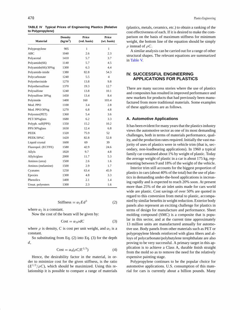
P1: GOX/LBD P2: GLQ Final Pages
Encyclopedia of Physical Science and Technology EN012K-587 July 26, 2001 10:35
470 Plastics Engineering
TABLE IV Typical Prices of Engineering Plastics (Relativeto Polypropylene)
Density Price PriceMaterial (kg/m3) (vol. basis) (wt. basis)
Polypropylene 905 1 1
ABC 1040 2.6 2.3
Polyacetal 1410 5.7 3.7
Polyamide(66) 1140 5.7 4.5
Polyamide(66)/30%g 1300 6.3 4.4
Polyamide-imide 1380 82.8 54.3
Polycarbonate 1240 5.5 4
Polyetherimide 1270 13.8 9.8
Polyethersulfone 1370 19.3 12.7
Polysulfone 1240 13.8 10.1
Polysulfone 30%g 1450 13.4 8.4
Polyimide 1400 160 103.4
Mod. PPO 1100 3.4 2.8
Mod. PPO/30%g 1270 6.8 4.8
Polyester(PET) 1360 5.4 3.6
PET/30%glass 1680 6.2 3.3
Polyph. sulf(PPS) 1350 15.2 10.2
PPS/30%glass 1650 12.4 6.8
PEEK 1320 75.9 52
PEEK/30%C 1420 82.8 52.8
Liquid crystal 1600 69 39
Fluoropol. (ECTFE) 1580 42.9 24.6
Allyls 1820 9.7 4.8
Allyls/glass 2000 11.7 5.3
Aminos (urea) 1500 2.6 1.6
Aminos (melamine) 1500 2.9 1.7
Cyanates 1250 63.4 45.9
Epoxies 1300 4.8 3.3
Phenolics 1400 2.1 1.4
Unsat. polyesters 1300 2.3 1.6
Stiffness = α2 Ed3 (2)
where α2 is a constant.Now the cost of the beam will be given by:
Cost = α3 ρdC (3)
where ρ is density, C is cost per unit weight, and α3 is aconstant.
So substituting from Eq. (2) into Eq. (3) for the depthd,
Cost = α4(ρC/E1/3) (4)
Hence, the desirability factor in the material, in or-der to minimize cost for the given stiffness, is the ratio(E1/3 /ρC), which should be maximized. Using this re-lationship it is possible to compare a range of materials
(plastics, metals, ceramics, etc.) to obtain a ranking of thecost effectiveness of each. If it is desired to make the com-parison on the basis of maximum stiffness for minimumweight, the bottom line of the equation should be simplyρ instead of ρC .
A similar analysis can be carried out for a range of otherstructural shapes. The relevant equations are summarizedin Table V.
IV. SUCCESSFUL ENGINEERINGAPPLICATIONS FOR PLASTICS
There are many success stories where the use of plasticsand composites has resulted in improved performance andnew markets for products that had previously been manu-factured from more traditional materials. Some examplesof these applications are as follows.
A. Automotive Applications
It has been evident for many years that the plastics industryviews the automotive sector as one of its most demandingchallenges, both in terms of materials performance, qual-ity, and the production rates required. Initially the vast ma-jority of uses of plastics were in vehicle trim (that is, sec-ondary, non-loadbearing applications). In 1960 a typicalfamily car contained about 1% by weight of plastic. Todaythe average weight of plastic in a car is about 175 kg, rep-resenting between 9 and 18% of the weight of the vehicle.
Interior trim still accounts for the biggest proportion ofplastics in cars (about 40% of the total) but the use of plas-tics in demanding under-the-hood applications is increas-ing rapidly and is expected to reach 20% soon. At presentmore than 25% of the air inlet units made for cars worldwide are plastic. Cost savings of over 50% are quoted inregard to this conversion from metal to plastic, accompa-nied by similar benefits in weight reduction. Exterior bodypanels also represent an exciting challenge for plastics interms of design for manufacture and performance. Sheetmolding compound (SMC) is a composite that is popu-lar in this sector, and at the current time approximately13 million units are manufactured annually for automo-tive use. Body panels from other materials such as PET orpolypropylene blends reinforced with glass fibers and al-loys of polycarbonate/polybutylene terephthalate are alsoproving to be very successful. A primary target in this ap-plication is to achieve a Class A, durable finish straightfrom the mold so as to remove the need for the relativelyexpensive painting stage.
Polypropylene continues to be the popular choice forautomotive applications. U.S. consumption of this mate-rial for cars is currently about a billion pounds. Many
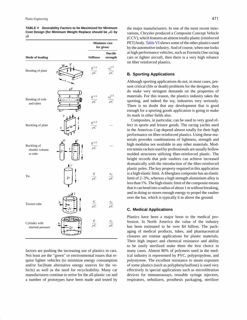
P1: GOX/LBD P2: GLQ Final Pages
Encyclopedia of Physical Science and Technology EN012K-587 July 26, 2001 10:35
Plastics Engineering 471
TABLE V Desirability Factors to be Maximized for MinimumCost Design (for Minimum Weight Replace should be ρC byρ)
Minimize costfor given:
DuctileMode of loading Stiffness strength
Bending of plate E1/2
ρC
σ1/2y
ρC
Bending of rods E1/2
ρC
σ2/3y
ρCand tubes
Buckling of plate E1/3
ρC —
Buckling of E1/2
ρC —
slender columnor tube
Tie E
ρC
σy
ρC
Torsion tube G
ρC
σy
ρC
Cylinder with E
ρC
σy
ρCinternal pressure
factors are pushing the increasing use of plastics in cars.Not least are the “green” or environmental issues that re-quire lighter vehicles (to minimize energy consumptionand/or facilitate alternative energy sources for the ve-hicle) as well as the need for recycleability. Many carmanufacturers continue to strive for the all-plastic car anda number of prototypes have been made and tested by
the major manufacturers. In one of the most recent inno-vations, Chrysler produced a Composite Concept Vehicle(CCV), which features an almost totally plastic (reinforcedPET) body. Table VI shows some of the other plastics usedby the automotive industry. And of course, when one looksat high performance vehicles, such as Formula One racingcars or fighter aircraft, then there is a very high relianceon fiber reinforced plastics.
B. Sporting Applications
Although sporting applications do not, in most cases, pre-sent critical (life or death) problems for the designer, theydo make very stringent demands on the properties ofmaterials. For this reason, the plastics industry takes thesporting, and indeed the toy, industries very seriously.There is no doubt that any development that is goodenough for a sporting goods application is going to makeits mark in other fields also.
Composites, in particular, can be used to very good ef-fect in sports and leisure goods. The racing yachts usedin the Americas Cup depend almost totally for their highperformance on fiber-reinforced plastics. Using these ma-terials provides combinations of lightness, strength andhigh modulus not available in any other materials. Mod-ern tennis rackets used by professionals are usually hollowmolded structures utilizing fiber-reinforced plastic. Theheight records that pole vaulters can achieve increaseddramatically with the introduction of the fiber-reinforcedplastic poles. The key property required in this applicationis a high elastic limit. A fiberglass composite has an elasticlimit of 2–3%, whereas a high strength aluminium alloy isless than 1%. The high elastic limit of the composite meansthat it can bend into a radius of about 1 m without breaking,and in doing so stores enough energy to propel the vaulterover the bar, which is typically 6 m above the ground.
C. Medical Applications
Plastics have been a major boon to the medical pro-fession. In North America the value of the industryhas been estimated to be over $4 billion. The pack-aging of medical products, tubes, and pharmaceuticalclosures are routine applications for plastic materials.Their high impact and chemical resistance and abilityto be easily sterilized make them the first choice inmany cases. Almost 80% of polymers used in the med-ical industry is represented by PVC, polypropylene, andpolystyrene. The excellent resistance to steam exposureof some plastics (such as polyphenylsulfone) is used veryeffectively in special applications such as microfiltrationdevices for immunoassays, reusable syringe injectors,respirators, nebulizers, prosthesis packaging, sterilizer

P1: GOX/LBD P2: GLQ Final Pages
Encyclopedia of Physical Science and Technology EN012K-587 July 26, 2001 10:35
472 Plastics Engineering
TABLE VI Application of Plastics in the Automotive Industry
Application Properties sought Typical materials used
Bumpers, fenders, side protection bars Impact resistance, paintability (or Class A finish) Polypropylene, alloys of PC, PPE/PA alloys
Fascias Rigidity, good surface detail Polypropylene
Body panels Rigidity, energy absorption, Class A finish Reinforced PP or PET, SMC or alloys of PC/PBT
Wheel arches UV resistance, impact strength, abrasion resistance PP, HDPE
Electrical components, gears, etc. High modulus, dimensionally stable PPS, PBT, polyacetal, reinforced nylons
Fuel tanks Impact resistance, low permeability HDPE, multi layers
Seat foams, soft touch trim Lightweight, flexible, durable Polyurethane
Grills Stiff, dimensionally stable, easily molded ABS, polypropylene
Cable sheathing Electrical and thermal resistance, impermeable to water PVC and cross-linked PE
Fuel lines Low permeability, flexible, tough Nylons, multi layer materials
Transparent fittings Clarity, surface hardness, toughness Polycarbonate acrylic (PMMA)
Washer bottles Tough, inert to chemicals, impermeable HDPE, PP
Headlights Tough, good optical properties Polycarbonate
Intake manifolds Stiff, high temperature and oil/fuel resistance Nylons
Safety belts High strength, flexible, tear resistant Nylons
trays, and dental tools. Polyetheretherketone (PEEK) issterilizable by autoclave, gas, or high-energy radiationand offers good chemical resistance. Common uses in-clude catheters, disposable surgical instruments, and ster-ilization trays. Polyurethane can be sterilized using dryheat, gas, or radiation, and its applications include tubing,catheters, connectors/fittings, pacemaker leads, tensioningligatures, wound dressings, and transdermal drug-deliverypatches. Polycarbonate and its blends are capable of beingsterilized by all the common methods, and its uses includeequipment housings and reservoirs. Liquid-crystal poly-mers (LCPs) can also be sterilized by all the commonmethods and are used in products such as dental tools,surgical instruments, and sterilizable trays.
Examples of life-saving devices based on the uniqueproperties of plastics are evident in every hospital wardand operating theater. Some typical examples are the use ofcarbon-fiber-reinforced plastics in operating tables, NMRimagers, and radiotherapy simulators. In these applica-tions the combination of lightness, strength, stiffness, andgood fatigue resistance are supplemented by relatively lowabsorption of X-rays. This means that much clearer,sharper images are obtained with lower dosages of ra-diation.
In general, the drive to reduce healthcare costs and theneed to use disposable medical supplies are importantfactors generating a higher demand of medical plastics.New materials, with improved properties, are beingdeveloped in order to satisfy the requirements of infectioncontrol standards. Current research is being conducted todetermine the biological reactivity of polymeric materials.Some new types of polymeric material can match veryclosely the performance of bone. This enables broken
limbs to be repaired or replaced by a synthetic materialthat is accepted by the human body and encourages newtissue growth.
Plastic/fiber composites are also being used very ef-fectively to meet the tough weight and strength demandsmade by artificial limbs. In this application lightness iscrucial because if, for example, a patient needs to havea whole leg replaced, the prothesis acts like a pendulumand is difficult to control if it is too heavy. The success-ful development of fiber composites in artificial limbs hasmeant that patients are able to adapt and use the new limbquickly and easily and without pain or discomfort.
D. Electrical Applications
The effects caused by static (electrostatic discharge, ESD)and electromagnetic/radiofrequency interference (EMI/RFI) are familiar as sparks jumping from fingertips toa doorknob or clothing and electronic noise in com-munications networks. In some cases these are just aninconvenience (or can be used to advantage such as inpackaging cling film), but when they are present in, on,or near electronic circuitry or flammable environments,they create hazards that must be or eliminated. ESD candamage or destroy electronic components, erase or al-ter magnetic data storage, and initiate explosions or fires.Electromagnetic and radiofrequency waves radiate fromcomputer circuits, radio transmitters (including cellularphones), fluorescent lamps, electric motors, lightning, andmany other sources. In most cases they are harmless butthey become undesirable when they interfere with otherelectrical equipment. An example of this is interferencewith medical devices such as pacemakers.

P1: GOX/LBD P2: GLQ Final Pages
Encyclopedia of Physical Science and Technology EN012K-587 July 26, 2001 10:35
Plastics Engineering 473
Plastics are inherently electrical insulators and they areoften used to exploit this characteristic. However, conduc-tive thermoplastics offer parts designers extra freedom inthe control of static (ESD) and EMI/RFI. The mechanismof conductivity in plastics is similar to that of most othermaterials. Electrons travel from point to point when undera driving force, following the path of least resistance. Con-ductive modifiers with low resistance can be melt blendedwith plastics to alter the polymers inherent electrical resis-tance. At a threshold concentration unique to each conduc-tive modifier and resin combination, the resistance throughthe plastic mass is lowered enough to allow electron move-ment. The speed of electron movement depends on themodifier concentration—in other words, on the separationbetween the modifier particles. Varying the percentage ortype of conductive additive used in the compound permitsone to control the degree of electrical resistivity. Nearly ev-ery type of polymer can be compounded with conductivefillers and most conductive thermoplastics can be made ina variety of colors.
The types of conductive additives that can be used in-clude carbon-based powder and fibers, metal powder andfibers, and metal-coated fibers of carbon or glass. Re-cently, unique conductive additives such as metal-coatedsubstrates, intrinsically conductive polymers (ICPs), andinherently dissipative polymers (IDPs) have found com-mercial use in conductive thermoplastic compounds.Conductive thermoplastic compounds prevent static accu-mulation from reaching dangerous levels by reducing theparts electrical resistance. This allows static to dissipateslowly and continuously rather than accumulate and dis-charge rapidly as a spark. Conductive thermoplastic com-pounds provide protection against EMI/RFI by absorbingelectromagnetic energy and converting it to electrical orthermal energy. They also function by reflecting energy.
There are numerous application areas for conductiveplastics in the computer industry in the form of hous-ings to protect sensitive electronics, and in industries usingpowders there is often a strong dependence on the uniquecharacteristics of these materials. In the pharmaceuticalindustry, for example, antistatic surfaces, containers, andpackaging must be used to eliminate dust attraction intothe product. An example of an application in the medi-cal field is the body for asthma inhalers where the correctdosage of the medication is critical and any static “cap-ture” of the fine-particulate drugs can affect recovery froma spasm.
E. Aircraft /Aerospace Applications
The very stringent demands that the aircraft/aerospacearea makes on materials has made it very much the fi-nal frontier for plastics and composites. The fact that
some plastics are already well established in this fieldis further confirmation that they have come of age asengineering materials. Plastics and composites are nowwidely used for primary and secondary components incivil and military aircraft. The Lear Jet and the BeechStarship are two examples of what can be achieved in thatthe complete outer structure of the planes utilize carbon-fiber-reinforced plastic (CFRP). Another very significantexample is the vertical and horizontal tail-plane of the Air-bus 320. These structures are predominantly made fromCFRP in both monolithic and honeycomb-cored sand-wich panels. Glass-fiber-reinforced plastics are used forthe bridging layers between the honeycomb cores and theCFRP skins. The weight saving achieved is about 20%,which represents a very considerable reduction in fuelconsumption or increase in payload. Another major ad-vantage of using composites in this type of application isthat the fabrication methods used reduce the number ofindividual parts that must be assembled. In the case of theAirbus 320 the reduction was from about 2000 parts inolder designs to less than 100 parts in the latest design.Future generations of commercial aircraft will make evenmore extensive use of plastic composites.
In military and space applications, the advantages ofcomposites are utilized to their utmost effect. The cost oflaunching rockets is so high that a high price can be tol-erated for any weight saving that can be achieved. As aresult, thousands of composite parts have been used suc-cessfully in spacecraft. The bank of information that hasbeen built up in this application area has shown that CFRPcan outperform other materials because of their very highspecific strengths and stiffnesses, excellent fatigue resis-tance, and low coefficients of thermal expansion. As thetrend continues toward longer design lifetimes of space-craft, it seems certain that the use of composites will alsocontinue to grow rapidly in this application area.
SEE ALSO THE FOLLOWING ARTICLES
CHEMICAL PROCESS DESIGN, SIMULATION, OPTIMIZA-TION, AND OPERATION • COMPOSITE MATERIALS • CON-STITUTIVE MODELS FOR ENGINEERING MATERIALS •FRACTURE AND FATIGUE • PLASTICITY • PLASTICIZERS
BIBLIOGRAPHY
Astrom, B. T. (1997). “Manufacturing of Polymer Composites,” Chap-man & Hall, London, p. 469.
Berins, M. L., ed. (1991). “Plastics Engineering Handbook,” 5th ed.,Hanser, Munich, p. 869.
Crawford, R. J. (1998). “Plastics Engineering,” Butterworth-Hein-emann, Oxford.

P1: GOX/LBD P2: GLQ Final Pages
Encyclopedia of Physical Science and Technology EN012K-587 July 26, 2001 10:35
474 Plastics Engineering
Domininghaus, H. (1993). “Plastics for Engineers,” Hanser, Munich,p. 785.
Dyson, R. W. (1990). “Engineering Polymers,” Chapman & Hall, NewYork, p. 195.
Epel, J. N., et al., eds. (1998). “Engineered Materials Handbook—Engi-neering Plastics,” Vol. 2, ASM International, Metals Park, OH, p. 882.
Gibson, L. J., and Ashby, M. F., “Cellular Solids,” 2nd ed., CambridgeUniversity Cambridge, U.K., p. 510.
Grosberg, A. Y., and Khokhlov, A. R. (1997). “Giant Molecules,”Academic Press, San Francisco, CA, p. 244.
Gruenwald, G. (1992). “Plastics—How Structure Determines Proper-ties,” Hanser, Munich, p. 357.
Huang, J. C. (1995). “EMI shielding plastics: a review,” Advances inPolymer Technology 14(2), 137–150.
Kelly, T., and Clyne, B. (1999). “Composite materials—reflections onthe first half century,” Physics Today Nov., 37–41.
Maier, C., and Calafut, T. (1998). “Polypropylene,” Plastics Design Li-brary, Norwich, NY, p. 432.
Mascia, L. (1989). “Thermoplastics: Materials Engineering,” 2nd ed.,Elsevier Applied Science, London, p. 537.
Mathews, G. (1996). “PVC: Production, Properties, and Uses,” Instituteof Materials, London, p. 379.
Miller, E. (1996). “Introduction to Plastics and Composites,” MarcelDekker, New York, p. 434.
Pardos, F. (1999). “Forecast for the World Plastic Industry to 2020,”Plastics Engineering 55(11), 53–57.
Portnoy, R. C. (1998). “Plastomer modified PP films for medical productpackaging,” Plastics Engineering 54(4), 33–35.
Reinhart, T. J., ed. (1987). “Engineered Materials Handbook—Com-posites,” Vol. 1, ASM International, Metals Park, OH, p. 983.
Saheb, D. N., and Jog, J. P. (1999). “Natural fiber polymer com-posites: a review,” Advances in Polymer Technology 18(4), 351–363.
Sawyer, L. C., Linstid, H. C., and Romer, M. (1998). “Emerging appli-cations for neat LCPs,” Plastics Engineering 54(12), 37–41.
Selke, S. E. M. (1997). In “Understanding Plastics Packaging Technol-ogy” (E. H. Immergut, ed.), p. 206, Hanser, Munich.
Throne, J. L. (1996). “Thermoplastic Foams,” Sherwood Publishers,Hinckley, OH, p. 692.
Walder, A. J. (1998). “Characteristics of medical polyurethanes,” Plas-tics Engineering 54(4), 29–31.
Weber, M. E. (1995). “The processing and properties of electrically con-ductive fiber composites,” In “Chemical Engineering,” McGill Uni-versity, Montreal, Canada.
Wigotsky, V. (1998). “Medical plastics,” Plastics Engineering 54(4),22–27.
Woods, G. (1987). “The ICI Polyurethanes Book,” Wiley, Chichester,p. 330.
P1: FMX/LSU P2: GPB/GRD P3: GLQ Final pages Qu: 00, 00, 00, 00
Encyclopedia of Physical Science and Technology EN012c-593 July 26, 2001 15:56
Polymer ProcessingDonald G. BairdVirginia Polytechnic Institute and State University
I. IntroductionII. Rheology of Polymer MeltsIII. Thermal Physical PropertiesIV. ExtrudersV. Compounding
VI. Extrusion DiesVII. Post-Die Processing
VIII. Molding and Forming
GLOSSARY
Blow molding A polymer tube, referred to as a parison ifextruded and a preform if injection molded, is expandedinto a cavity by means of air pressure where it is rapidlysolidified on contact with the mold walls. It is used forproducing hollow objects such as bottles, containers,and fuel tanks.
Compounding The process by which other polymers andorganic and inorganic additives are combined with apolymer to improve processing performance and prop-erties of the given polymer.
Compression molding A process by which a polymermass is subjected to high mechanical pressure withina cavity to cause it to take the shape of the cavity,solidified, and the part removed. Used primarily forhighly filled polymers with a high viscosity and forhighly filled thermosetting resins.
Extruder A device used to melt and pump polymericfluids consisting of a screw rotating within a metallicbarrel.
Extrusion die A metal channel attached to the end ofan extruder to provide shape to an emerging polymerstream.
Film blowing An extrusion process for producing thinfilms of polymers with biaxial orientation based on ex-truding from an annular die and subjecting the bubble toboth axial (drawing) and radial (air pressure) stretching.
Injection molding A cyclic automated process by whichpolymer pellets are melted in an extruder, the melt isinjected into a cavity, solidified, and the part removed.The process is used to make small intricate parts as wellas large parts for automobiles.
Melt index The mass flow of a fluid (in grams) in theperiod of 10 min from a capillary of known dimensionsunder a specified pressure and temperature.
Newtonian fluid A fluid in which the shear stress is lin-early proportional to the velocity gradient; i.e., a fluidof constant viscosity.
Non-Newtonian fluid A fluid whose viscosity is not con-stant and may exhibit a wide range of time-dependentresponses.
611

P1: FMX/LSU P2: GPB/GRD P3: GLQ Final pages
Encyclopedia of Physical Science and Technology EN012c-593 July 26, 2001 15:56
612 Polymer Processing
Rheology Science of the deformation and flow ofmaterials.
Rheometry The equipment and process by which the rhe-ological properties of polymeric fluids are determined.
Thermoforming A process by which a sheet of polymeris heated, usually by radiation heating, to the point atwhich it is pliable and then pushed or pulled into a cav-ity by applied mechanical force or pressure or appliedvacuum. Used frequently for producing materials forpackaging applications, but large parts for recreationaluse can also be produced.
Viscoelasticity The response of a fluid or solid which isa combination of viscous and elastic behavior as deter-mined by the rate of deformation relative to the relax-ation time of the material.
IN THE CONTEXT of this article, polymer processingrefers to the operations by which polymer resin is con-verted to finished plastic parts and objects. Of particular in-terest are those resins referred to as thermoplastics whichcan be softened by the application of heat, processed, so-lidified, and reheated and processed again. This is opposedto thermosetting resins which, once solidified via the pro-cess of cross-linking, cannot be softened for reprocessing.Virgin resin is rarely processed; instead, a wide variety ofadditives are compounded into the resin to improve pro-cessing performance and properties. These resins plus ap-propriate additives are then heated and shaped by flow anddeformation using a number of processing operations (ex-trusion, injection molding, film blowing, fiber spinning,blow molding, thermoforming, compression molding,etc.).
I. INTRODUCTION
The conversion of polymers to finished parts and arti-cles differs significantly from that used to process lowmolar mass (sometimes molecular weight is used) fluidsbecause of their unique molecular features that lead tohigh viscosity and viscoelastic behavior. Polymeric mate-
FIGURE 1 Entangled macromolecules in the undeformed and deformed states.
rials typically have molar masses in the range of 20,000to 150,000 g/g-mol. When the molar masses are greaterthan some critical value, Mc, the large molecules physi-cally entangle with each other as shown schematically inFig. 1. This entanglement network leads to not only highlyviscous fluids but fluids with elastic properties. Under fi-nite deformations, macromolecules stretch, disentangle,and orient (Fig. 1). On cessation of flow, thermal motioncauses the molecules to recover their initial conforma-tion and re-entangle. As a result of this recovery process,polymeric fluids partially resemble purely elastic materi-als such as cross-linked rubber and are therefore referredto as being viscoelastic.
The processing behavior of polymeric melts is highlydependent on several molecular features. The size of themolecule or its molar mass is one of the key factors. Poly-mers rarely consist of a single molar mass; they are insteada distribution of molar masses. Because of the distributionof chain sizes it is common to use moments of the distri-bution to specify the molar mass of a resin. For example,the number average molar mass, Mn, is the total mass ofpolymer divided by the number of polymeric chains (i.e.,the average molecular weight). The weight average molarmass, Mw, is the number of chains of given weight timesthe weight of material with that given molar mass dividedby the total weight of polymer. It is a higher moment ofthe distribution. The ratio of Mw/Mn is referred to as thepolydispersity of the polymer. For polymers synthesizedby means of a step polymerization process (e.g., PET andnylon), this ratio is around 2.0 (the most probable distri-bution), whereas for polymers produced by means of ad-dition polymerization (polyethylenes), the ratio can varyfrom 4.0 to 30.0. With the advent of metallocene catalysts,polyethylenes with polydispersity indices in the range of2.0 are possible.
Although techniques such as gel permeation chro-matography or size exclusion chromatography are typ-ically used to provide details about the molar massdistribution, several other techniques are used by man-ufactures to specify the molar mass of their polymers. Forpolymers such as those produced via means of step poly-merization the inherent viscosity (IV) is commonly used.

P1: FMX/LSU P2: GPB/GRD P3: GLQ Final pages
Encyclopedia of Physical Science and Technology EN012c-593 July 26, 2001 15:56
Polymer Processing 613
The IV is obtained from measurements of the viscosity ofa dilute polymer solution relative to the viscosity of thesolvent. Typically, it measured at a specific polymer con-centration. The IV is directly related to the intrinsic vis-cosity, which is obtained by the extrapolation of solutionviscosities to zero polymer concentration. Well-knownrelations between the intrinsic viscosity and the molarmass of a polymer exist (this relation is referred to as theMark–Houwink relation). For polymers such as those pro-duced by means of addition reactions, the melt index (MI)is used to categorize the molar mass. The measurement ofMI is discussed in the rheology section.
Another factor affecting processing is whether the chainis linear or branched. Branching refers to arms that extendfrom the main backbone of a chain. These branches maybe long or short depending on whether the molar massof the branch, M , is greater than the critical molar massfor entanglements, Mc, or less than Mc. Branching may bequite dense, in which every chain contains many branches,or sparse, in which not every chain contains a branch.The branching architecture can be described as random,comb, star, or H . Random branching involves irregularspacing of the branches along the backbone as well as thebranches. Combs are systems in which the branches pro-trude from one side of the chain. Star-branched polymersconsist of three or four arms emanating from a centralpoint. H-branched polymers consist of multiple branchesat the end of the chains. The processing behavior as wellas the mechanical properties of a polymer are dependenton the branching architecture.
The thermal conditions for processing are determinedby two important thermal transition temperatures. Thesetemperatures are the glass transition temperature, Tg, andthe melting point, Tm. For amorphous polymers that ex-hibit no crystallinity, the Tg determines where it becomesdeformable and, hence, processible. For semicrystallinepolymers, Tm determines the primary temperature at whichthe polymer will flow and become processible. Somesemicrystalline polymers can be processed to limit theformation of crystallinity and thereby behave somewhatlike an amorphous polymer. Temperature Tg is associatedwith an increase in free volume, which allows mobilityof the polymer chains. Hence, one must be above Tg toprocess amorphous polymers.
II. RHEOLOGY OF POLYMER MELTS
A. Purely Viscous Behavior
When a simple fluid, such as water, is placed between thetwo plates, as shown in Fig. 2, in which the top plate ismoved to the right with constant velocity, V , the relation
FIGURE 2 Steady simple shear flow with shear rate equal to V /b.
between force, F , divided by the area of the plates, A, andthe velocity divided by the separation distance, b, is givenas follows:
F
A= µ
V
b . (1)
The constant of proportionality, µ, is called the viscosityof the fluid. F is the force required to keep the top platemoving with a constant velocity. The force per unit areaacting in the x direction on a fluid surface at constant yby the fluid in the region of lesser y is the shear stress,τyx . Because the velocity of the fluid particles varies in alinear manner with respect to the y coordinate, it is clearthat V /b = d vx /dy, which is the derivative of the velocitywith respect to the distance y. Equation (1) can be rewrittenas:
τyx = −µ(d vx /dy). (2)
This states that the shear force per unit area is propor-tional to the negative of the local velocity gradient andis known as Newton’s law of viscosity. Fluids that obeythis simple linear relationship are termed Newtonian flu-ids. From Eq. (2) we can determine the dimensions ofviscosity, which are mass/unit length/unit time. For theSysteme International (SI), the units of viscosity are Pasec (or kg/m/s), whereas for the CGS system they are thePoise (dyn/cm2/sec or g/cm/sec).
The flow behavior of most thermoplastics does not fol-low Newton’s law of viscosity. To quantitatively describethe viscous behavior of polymeric fluids, Newton’s law ofviscosity is generalized as follows:
τyx = −η d vx /dy, (3)
where η can be expressed as a function of either d vx/dy orτyx . Some typical responses of polymeric fluids are shownin Fig. 3, where τyx is plotted versus the velocity gradient.For a pseudoplastic fluid, the slope of the line decreaseswith increasing magnitude of dvx/dy, or in essence theviscosity decreases. Some polymeric fluids (in some casespolymer blends and filled polymers) exhibit a yield stress,which is the stress that must be overcome before flow

P1: FMX/LSU P2: GPB/GRD P3: GLQ Final pages
Encyclopedia of Physical Science and Technology EN012c-593 July 26, 2001 15:56
614 Polymer Processing
FIGURE 3 Shear stress versus velocity gradient or shear rate forseveral different types of fluids. [From Baird, D. G., and Collias, D. I.(1998). “Polymer Processing: Principles and Design,” Wiley,New York.]
can occur. When flow occurs, if the slope of the line isconstant, then the fluid is referred to as a Bingham fluid.In many cases the fluid is still pseudoplastic once flowbegins. Finally, in some cases the viscosity of the materialincreases with increasing velocity gradient. The fluid isthen referred to as being dilatant.
Many empiricisms have been proposed to describe thesteady state relation between τyx and dvx/dy, but we men-tion only a few of the most useful for polymeric fluids. Thefirst is the power law of Ostwald and de Waele:
η = m
∣∣∣∣dvx
dy
∣∣∣∣n−1
. (4)
This is a two-parameter model in which n describes thedegree of deviation from Newtonian behavior; m, whichhas the units of Pa secn , is called the consistency. For n = 1and m = µ, this model predicts Newtonian fluid behavior.For n < 1, the fluid is pseudoplastic while for n > 1 thefluid is dilatant. It particular, the model describes the vis-cosity behavior as shown in Fig. 4 in the region where theviscosity decreases linearly with increasing velocity gra-dient (which is also called shear rate). The curves shownin Fig. 4 are also referred to as flow curves. Actually mostpolymeric fluids exhibit a constant viscosity at low shearrates and then shear thin at higher shear rates (Fig. 4).A model that is used often in numerical calculations, be-cause it fits the full flow curve, is the Carreau–Yasudamodel:
η − η∞η0 − η∞
=[
1 +(
λdvx
dy
)a] n−1a
. (5)
This model contains five parameters: η0, η∞, λ, a, andn. η0 is the zero shear viscosity just as above; η∞ is theviscosity as the shear rate or dvx/dy goes to very high
FIGURE 4 Viscosity versus shear rate (i.e., flow curves) for ametallocene catalyzed polyethylene at temperatures of 170 and190◦C.
values (e.g., >10,000 sec−1) and for polymer melts thiscan be taken as zero; λ has units of seconds and approx-imately represents the reciprocal of the shear rate for theonset of shear thinning behavior; and n represents the de-gree of shear thinning and is nearly the same as the valuein the power-law model. Finally, a is a parameter thatcontrols how sharp the transition is into shear-thinningbehavior.
B. Viscoelastic Behavior
The term viscoelastic behavior refers to the fact that apolymeric fluid can exhibit a response which resemblesthat of an elastic solid under some circumstances, whileunder others it can act as a viscous liquid. Viscosity aloneis not sufficient to describe the flow behavior of polymermelts. Additional material functions are needed which re-flect their viscoelastic nature. Before defining several ofthe most important material functions in addition to vis-cosity, it is necessary to discuss the kinematics or defor-mation associated with these material functions.
Two basic flows are used to characterize polymers:shear and shear-free flows. (It so happens that processesare usually a combination of these flows or sometimes aredominated by one type or the other.) The velocity field forrectilinear shear flow (Fig. 2) is given below:
vx = γ (t)y vy = vz = 0, (6)
where γ (t) may be constant or a function of time. Thevelocity field for shear-free flows can be given in a generalform as
vx = −1/2 ε (1 + b)x,
vy = −1/2 ε (1 − b)y, (7)
vz = + εz,
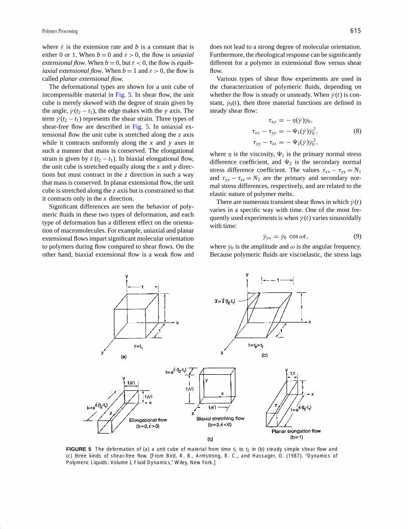
P1: FMX/LSU P2: GPB/GRD P3: GLQ Final pages
Encyclopedia of Physical Science and Technology EN012c-593 July 26, 2001 15:56
Polymer Processing 615
where ε is the extension rate and b is a constant that iseither 0 or 1. When b = 0 and ε > 0, the flow is uniaxialextensional flow. When b = 0, but ε < 0, the flow is equib-iaxial extensional flow. When b = 1 and ε > 0, the flow iscalled planar extensional flow.
The deformational types are shown for a unit cube ofincompressible material in Fig. 5. In shear flow, the unitcube is merely skewed with the degree of strain given bythe angle, γ (t2 − t1), the edge makes with the y axis. Theterm γ (t2 − t1) represents the shear strain. Three types ofshear-free flow are described in Fig. 5. In uniaxial ex-tensional flow the unit cube is stretched along the z axiswhile it contracts uniformly along the x and y axes insuch a manner that mass is conserved. The elongationalstrain is given by ε (t2 − t1). In biaxial elongational flow,the unit cube is stretched equally along the x and y direc-tions but must contract in the z direction in such a waythat mass is conserved. In planar extensional flow, the unitcube is stretched along the z axis but is constrained so thatit contracts only in the x direction.
Significant differences are seen the behavior of poly-meric fluids in these two types of deformation, and eachtype of deformation has a different effect on the orienta-tion of macromolecules. For example, uniaxial and planarextensional flows impart significant molecular orientationto polymers during flow compared to shear flows. On theother hand, biaxial extensional flow is a weak flow and
FIGURE 5 The deformation of (a) a unit cube of material from time t1 to t2 in (b) steady simple shear flow and(c) three kinds of shear-free flow. [From Bird, R. B., Armstrong, R. C., and Hassager, O. (1987). “Dynamics ofPolymeric Liquids: Volume I, Fluid Dynamics,” Wiley, New York.]
does not lead to a strong degree of molecular orientation.Furthermore, the rheological response can be significantlydifferent for a polymer in extensional flow versus shearflow.
Various types of shear flow experiments are used inthe characterization of polymeric fluids, depending onwhether the flow is steady or unsteady. When γ (t) is con-stant, γ0(t), then three material functions are defined insteady shear flow:
τxy = − η(γ )γ0,
τxx − τyy = − �1(γ )γ 20 , (8)
τyy − τzz = − �2(γ )γ 20 ,
where η is the viscosity, �1 is the primary normal stressdifference coefficient, and �2 is the secondary normalstress difference coefficient. The values τxx − τyy = N1
and τyy − τzz = N2 are the primary and secondary nor-mal stress differences, respectively, and are related to theelastic nature of polymer melts.
There are numerous transient shear flows in which γ (t)varies in a specific way with time. One of the most fre-quently used experiments is when γ (t) varies sinusoidallywith time:
γyx = γ0 cos ωt, (9)
where γ0 is the amplitude and ω is the angular frequency.Because polymeric fluids are viscoelastic, the stress lags
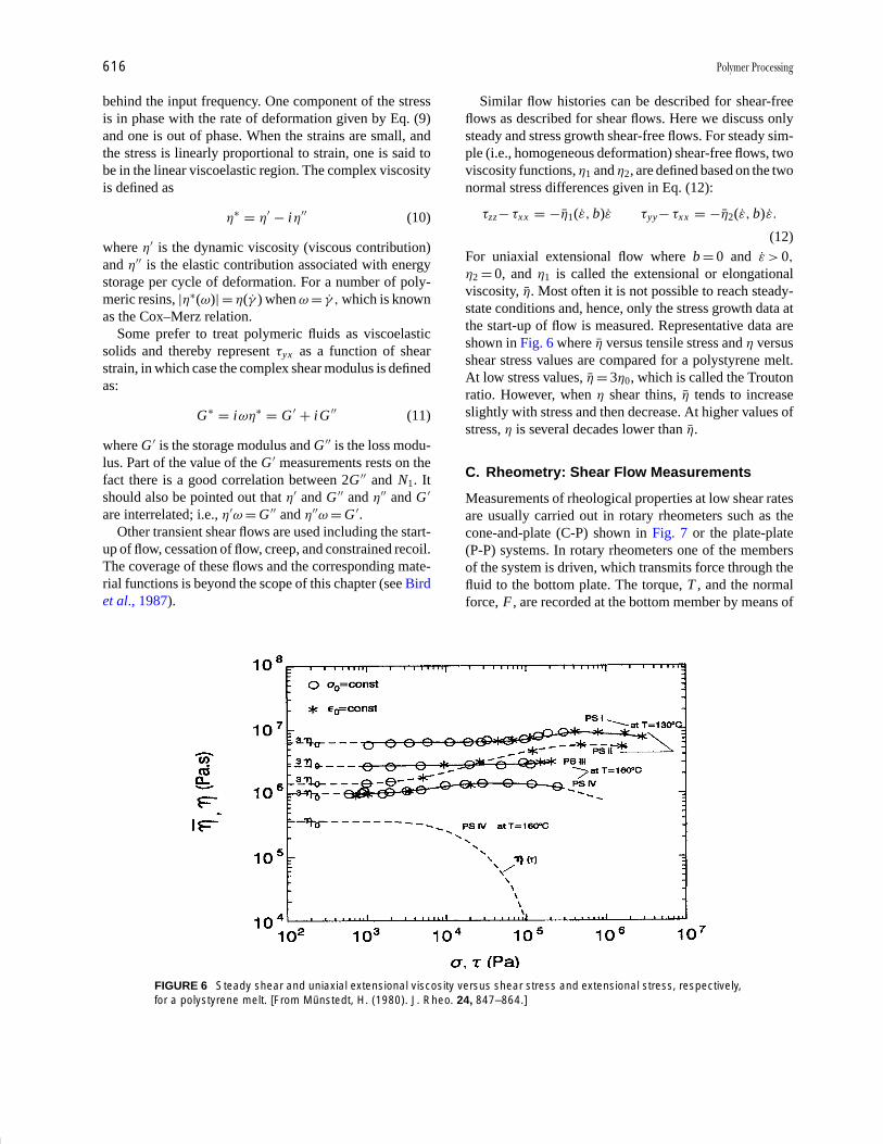
P1: FMX/LSU P2: GPB/GRD P3: GLQ Final pages
Encyclopedia of Physical Science and Technology EN012c-593 July 26, 2001 15:56
616 Polymer Processing
behind the input frequency. One component of the stressis in phase with the rate of deformation given by Eq. (9)and one is out of phase. When the strains are small, andthe stress is linearly proportional to strain, one is said tobe in the linear viscoelastic region. The complex viscosityis defined as
η∗ = η′ − i η′′ (10)
where η′ is the dynamic viscosity (viscous contribution)and η′′ is the elastic contribution associated with energystorage per cycle of deformation. For a number of poly-meric resins, |η∗(ω)| = η( γ ) when ω = γ , which is knownas the Cox–Merz relation.
Some prefer to treat polymeric fluids as viscoelasticsolids and thereby represent τyx as a function of shearstrain, in which case the complex shear modulus is definedas:
G ∗ = i ωη∗ = G ′ + iG ′′ (11)
where G ′ is the storage modulus and G ′′ is the loss modu-lus. Part of the value of the G ′ measurements rests on thefact there is a good correlation between 2G ′′ and N1. Itshould also be pointed out that η′ and G ′′ and η′′ and G ′
are interrelated; i.e., η′ω = G ′′ and η′′ω = G ′.Other transient shear flows are used including the start-
up of flow, cessation of flow, creep, and constrained recoil.The coverage of these flows and the corresponding mate-rial functions is beyond the scope of this chapter (see Birdet al., 1987).
FIGURE 6 Steady shear and uniaxial extensional viscosity versus shear stress and extensional stress, respectively,for a polystyrene melt. [From Munstedt, H. (1980). J. Rheo. 24, 847–864.]
Similar flow histories can be described for shear-freeflows as described for shear flows. Here we discuss onlysteady and stress growth shear-free flows. For steady sim-ple (i.e., homogeneous deformation) shear-free flows, twoviscosity functions, η1 and η2, are defined based on the twonormal stress differences given in Eq. (12):
τzz − τxx = −η1(ε, b)ε τyy − τxx = −η2(ε, b)ε.
(12)For uniaxial extensional flow where b = 0 and ε > 0,
η2 = 0, and η1 is called the extensional or elongationalviscosity, η. Most often it is not possible to reach steady-state conditions and, hence, only the stress growth data atthe start-up of flow is measured. Representative data areshown in Fig. 6 where η versus tensile stress and η versusshear stress values are compared for a polystyrene melt.At low stress values, η = 3η0, which is called the Troutonratio. However, when η shear thins, η tends to increaseslightly with stress and then decrease. At higher values ofstress, η is several decades lower than η.
C. Rheometry: Shear Flow Measurements
Measurements of rheological properties at low shear ratesare usually carried out in rotary rheometers such as thecone-and-plate (C-P) shown in Fig. 7 or the plate-plate(P-P) systems. In rotary rheometers one of the membersof the system is driven, which transmits force through thefluid to the bottom plate. The torque, T , and the normalforce, F , are recorded at the bottom member by means of

P1: FMX/LSU P2: GPB/GRD P3: GLQ Final pages
Encyclopedia of Physical Science and Technology EN012c-593 July 26, 2001 15:56
Polymer Processing 617
FIGURE 7 Cone-and-plate rheometer. The geometric variablesare the cone angle, ϑ0, and the radius, R. The torque, T , requiredto turn the cone at an angular velocity W is converted to viscositywhile the normal force exerted on the bottom plate is convertedto the primary normal stress difference.
transducers. The C-P configuration has the advantagethat the shear rate is nearly uniform through the gap. Be-cause the shear rate is uniform throughout the gap, it ispossible to use the C-P to measure the transient responseof polymeric fluids. For the case of the P-P device theshear rate varies with the distance r from the center of theplates. Hence, one must make a series of measurementsat various shear rates before obtaining values of η and�1 − �2 at specific values of shear rate. For the C-P de-vice the maximum shear rate for which measurements arepossible (the melt usually fractures and comes out of thegap) is about 1 sec−1 while slightly higher values of shearrate are possible with the P-P device.
The capillary rheometer (Fig. 8) is commonly used toobtain η at high shear rates. Basically the device consistsof a barrel for melting the polymer and a plunger thatpushes the melt through the capillary. The data obtainedfrom this device consist of the pressure required to pushthe melt through the capillary and the volumetric flow rate(plunger speed and cross-sectional area). Two correctionsare applied to these data. First, the pressure drop must becorrected for the additional pressure required for the meltto pass through the contraction between the barrel and thecapillary. For any fluid, the wall shear stress is given by:
τR =(−dp
dz
)R
2 , (13)
where dp/dz is the pressure gradient in the capillary. Usu-ally −dp/dz is approximated by �P /L , where �P is thepressure drop across the whole capillary including the en-trance and L is the capillary length. For a Newtonian fluidthe pressure gradient is nearly constant over the length ofthe capillary. The pressure gradient is nonlinear for poly-
FIGURE 8 A capillary rheometer in which polymer pellets aremelted by heat conducted through the barrel and then pushed bythe plunger through the capillary. Viscosity data are obtained fromthe force and plunger speed measurements. [From Baird, D. G.,and Collias, D. I. (1998).“Polymer Processing: Principles and De-sign,” Wiley, New York.]
meric materials and approximating it as �P/L would leadto large errors in the determination of τR . The differencebetween the pressure extrapolated from the linear regionand the true pressure is called the entrance pressure, �Pent.There may be residual pressure at the die exit, called theexit pressure, �Pex, but it is quite small relative to �Pent
and hence is neglected. If there is additional pressure atthe die exit, then the method used to obtain �Pent actuallyincludes �Pex. The total pressure correction for exit andentrance regions is called the end pressure, �Pend, i.e.,
�Pend = �Pex + �Pent. (14)
The true wall shear stress, τR , is then obtained by plottingthe total pressure, �Ptot, versus L/D at each value of shearrate for several L/D values (these are called Bagley plots).The extrapolation of �Ptot to L/D = 0 is �Pend. One nowobtains τR as follows:
τR =(
�Ptot − �Pend
L
)R
2. (15)
Because the velocity profile is nonparabolic, one must cor-rect the apparent wall shear rate, γa, defined as 4Q/πR3.The true wall shear rate for a shear-thinning fluid is:
γw = γa
4
(3 + d ln γa
d ln τR
). (16)
Hence, by plotting τR versus γa on a ln–ln plot one obtainsthe reciprocal of the required correction factor. It turns outthat this value is just 1/n, where n is the power-law index.
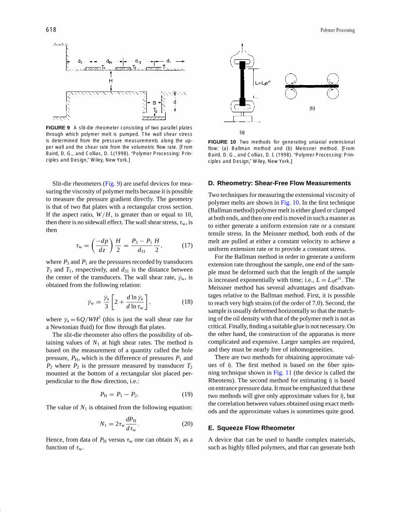
P1: FMX/LSU P2: GPB/GRD P3: GLQ Final pages
Encyclopedia of Physical Science and Technology EN012c-593 July 26, 2001 15:56
618 Polymer Processing
FIGURE 9 A slit-die rheometer consisting of two parallel platesthrough which polymer melt is pumped. The wall shear stressis determined from the pressure measurements along the up-per wall and the shear rate from the volumetric flow rate. [FromBaird, D. G., and Collias, D. I.(1998). “Polymer Processing: Prin-ciples and Design,” Wiley, New York.]
Slit-die rheometers (Fig. 9) are useful devices for mea-suring the viscosity of polymer melts because it is possibleto measure the pressure gradient directly. The geometryis that of two flat plates with a rectangular cross section.If the aspect ratio, W /H , is greater than or equal to 10,then there is no sidewall effect. The wall shear stress, τw, isthen
τw =(−dp
dz
)H
2= P3 − P1
d31
H
2, (17)
where P3 and P1 are the pressures recorded by transducersT3 and T1, respectively, and d31 is the distance betweenthe center of the transducers. The wall shear rate, γw, isobtained from the following relation:
γw = γa
3
[2 + d ln γa
d ln τw
], (18)
where γa = 6Q /WH2 (this is just the wall shear rate fora Newtonian fluid) for flow through flat plates.
The slit-die rheometer also offers the possibility of ob-taining values of N1 at high shear rates. The method isbased on the measurement of a quantity called the holepressure, PH, which is the difference of pressures P1 andP2 where P2 is the pressure measured by transducer T2
mounted at the bottom of a rectangular slot placed per-pendicular to the flow direction, i.e.:
PH = P1 − P2 . (19)
The value of N1 is obtained from the following equation:
N1 = 2τwdPH
d τw. (20)
Hence, from data of PH versus τw one can obtain N1 as afunction of τw.
FIGURE 10 Two methods for generating uniaxial extensionalflow: (a) Ballman method and (b) Meissner method. [FromBaird, D. G., and Collias, D. I. (1998). “Polymer Processing: Prin-ciples and Design,” Wiley, New York.]
D. Rheometry: Shear-Free Flow Measurements
Two techniques for measuring the extensional viscosity ofpolymer melts are shown in Fig. 10. In the first technique(Ballman method) polymer melt is either glued or clampedat both ends, and then one end is moved in such a manner asto either generate a uniform extension rate or a constanttensile stress. In the Meissner method, both ends of themelt are pulled at either a constant velocity to achieve auniform extension rate or to provide a constant stress.
For the Ballman method in order to generate a uniformextension rate throughout the sample, one end of the sam-ple must be deformed such that the length of the sampleis increased exponentially with time; i.e., L = L0eεt . TheMeissner method has several advantages and disadvan-tages relative to the Ballman method. First, it is possibleto reach very high strains (of the order of 7.0). Second, thesample is usually deformed horizontally so that the match-ing of the oil density with that of the polymer melt is not ascritical. Finally, finding a suitable glue is not necessary. Onthe other hand, the construction of the apparatus is morecomplicated and expensive. Larger samples are required,and they must be nearly free of inhomogeneities.
There are two methods for obtaining approximate val-ues of η. The first method is based on the fiber spin-ning technique shown in Fig. 11 (the device is called theRheotens). The second method for estimating η is basedon entrance pressure data. It must be emphasized that thesetwo methods will give only approximate values for η, butthe correlation between values obtained using exact meth-ods and the approximate values is sometimes quite good.
E. Squeeze Flow Rheometer
A device that can be used to handle complex materials,such as highly filled polymers, and that can generate both

P1: FMX/LSU P2: GPB/GRD P3: GLQ Final pages
Encyclopedia of Physical Science and Technology EN012c-593 July 26, 2001 15:56
Polymer Processing 619
FIGURE 11 Rheotens apparatus for estimating uniaxial exten-sional viscosity. [From Baird, D. G., and Collias, D. I. (1998). “Poly-mer Processing: Principles and Design,” Wiley, New York.]
shear and shear-free flows is the squeezing-flow rheome-ter shown in Fig. 12. For small gaps and no slip at thewalls, the kinematics are primarily that of shear flow. Forlarge gaps and in the presence of lubrication at the inter-face between the plates and polymer, biaxial extensional
FIGURE 12 Squeezing-flow rheometer showing displacement of parallel disks. [From Baird, D. G., and Collias, D. I.(1998). “Polymer Processing: Principles and Design,” Wiley, New York.]
flow is generated. The device can be operated by eitherapplying a constant squeeze rate or a constant force. Thedevice is very useful for making viscosity measurementson fluids with high viscosity (e.g., η > 105 Pa sec) such ascomposite materials containing long-fiber reinforcementor propellants.
F. Effect of Molar Mass on Viscosity
Molar mass (M) has a significant effect on the rheologicalproperties of polymer melts and hence on their processingperformance. At low molar mass, i.e., below some criticalmolar mass (Mc), for flexible chain polymers η0 dependson Mw , while above Mc, η0 depends on Mw to the 3.4 to3.6 power for most flexible linear polymer chains:
η0 ∝{
Mw for Mw < Mc
M3.4w for Mw > Mc
. (21)
The 3.4 power dependence has been observed experimen-tally and predicted theoretically. Furthermore, the primarynormal stress difference coefficient in the limit as the shearrate goes to zero, �1,0, is observed to be proportional toMw raised to the 7.0 power, i.e.:
�1,0 ∝ η20 ∝ M7.0
w . (22)
For branched polymers the dependence of η0 on Mw canbe to higher or lower powers than 3.4 to 3.6 depending onthe molecular weight between branch points. For rodlike
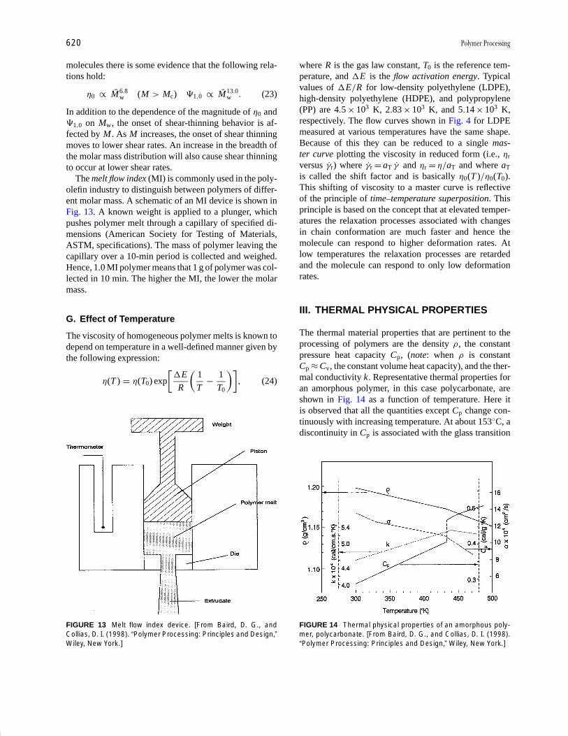
P1: FMX/LSU P2: GPB/GRD P3: GLQ Final pages
Encyclopedia of Physical Science and Technology EN012c-593 July 26, 2001 15:56
620 Polymer Processing
molecules there is some evidence that the following rela-tions hold:
η0 ∝ M6.8w (M > Mc) �1,0 ∝ M13.0
w . (23)
In addition to the dependence of the magnitude of η0 and�1,0 on Mw, the onset of shear-thinning behavior is af-fected by M . As M increases, the onset of shear thinningmoves to lower shear rates. An increase in the breadth ofthe molar mass distribution will also cause shear thinningto occur at lower shear rates.
The melt flow index (MI) is commonly used in the poly-olefin industry to distinguish between polymers of differ-ent molar mass. A schematic of an MI device is shown inFig. 13. A known weight is applied to a plunger, whichpushes polymer melt through a capillary of specified di-mensions (American Society for Testing of Materials,ASTM, specifications). The mass of polymer leaving thecapillary over a 10-min period is collected and weighed.Hence, 1.0 MI polymer means that 1 g of polymer was col-lected in 10 min. The higher the MI, the lower the molarmass.
G. Effect of Temperature
The viscosity of homogeneous polymer melts is known todepend on temperature in a well-defined manner given bythe following expression:
η(T ) = η(T0) exp
[�E
R
(1
T− 1
T0
)], (24)
FIGURE 13 Melt flow index device. [From Baird, D. G., andCollias, D. I. (1998). “Polymer Processing: Principles and Design,”Wiley, New York.]
where R is the gas law constant, T0 is the reference tem-perature, and �E is the flow activation energy. Typicalvalues of �E /R for low-density polyethylene (LDPE),high-density polyethylene (HDPE), and polypropylene(PP) are 4.5 × 10³ K, 2.83 × 10³ K, and 5.14 × 10³ K,respectively. The flow curves shown in Fig. 4 for LDPEmeasured at various temperatures have the same shape.Because of this they can be reduced to a single mas-ter curve plotting the viscosity in reduced form (i.e., ηr
versus γr) where γr = aT γ and ηr = η/aT and where aT
is called the shift factor and is basically η0(T )/η0(T0).This shifting of viscosity to a master curve is reflectiveof the principle of time–temperature superposition. Thisprinciple is based on the concept that at elevated temper-atures the relaxation processes associated with changesin chain conformation are much faster and hence themolecule can respond to higher deformation rates. Atlow temperatures the relaxation processes are retardedand the molecule can respond to only low deformationrates.
III. THERMAL PHYSICAL PROPERTIES
The thermal material properties that are pertinent to theprocessing of polymers are the density ρ, the constantpressure heat capacity Cp, (note: when ρ is constantCp ≈ Cv, the constant volume heat capacity), and the ther-mal conductivity k. Representative thermal properties foran amorphous polymer, in this case polycarbonate, areshown in Fig. 14 as a function of temperature. Here itis observed that all the quantities except Cp change con-tinuously with increasing temperature. At about 153◦C, adiscontinuity in Cp is associated with the glass transition
FIGURE 14 Thermal physical properties of an amorphous poly-mer, polycarbonate. [From Baird, D. G., and Collias, D. I. (1998).“Polymer Processing: Principles and Design,” Wiley, New York.]

P1: FMX/LSU P2: GPB/GRD P3: GLQ Final pages
Encyclopedia of Physical Science and Technology EN012c-593 July 26, 2001 15:56
Polymer Processing 621
temperature, Tg. At Tg there is an increase in the freevolume allowing molecules more freedom of movement.Above Tg, the polymer chains become more mobile andmore easily deformed. It is observed that above Tg there isvery little change in the thermal properties. For example,Cp changes from 0.46 kcal/g K at 435 K to 0.5 kcal/g Kat 480 K (K is degrees Kelvin). The thermal conductivitychanges even less. The density changes less than 5% overthe whole temperature range shown. On the other hand,the changes in thermal properties for a semicrystallinepolymer are more distinct as shown in Fig. 15. Here it isobserved that Cp increases rapidly with temperature pass-ing through a maximum and then decreasing with temper-ature. The temperature at the peak value is taken as themelting point, Tm. The area under the curve is associatedwith the melting of the crystalline phase and is referred toas the heat of fusion, �Hf. Above Tm the thermal proper-ties are observed not to change significantly with temper-ature. The density changes markedly for polypropylenevarying from about 0.5 g/cm3 at 300◦C to 0.9 g/cm3 at50◦C. This large change in density leads to large changesin the dimensions of parts on cooling down from themelt and can lead to warpage of large injection moldedpanels.
For semicrystalline polymers it is observed that melt-ing occurs leading to the absorption of energy. The energy
FIGURE 15 Thermal physical properties of a semicrystallinepolymer, polypropylene. [From Baird, D. G., and Collias, D. I.(1998). “Polymer Processing: Principles and Design,” Wiley, NewYork.]
associated with the change from the crystalline phase tothe completely amorphous state is obtained by integratingthe area under the curve of Cp versus temperature. Theenergy associated with this phase transition is called theheat of fusion, �Hf. Note also that the melting point is notreally distinct, but covers a broad temperature range. Thecooling of a semicrystalline polymer from a temperatureabove Tm to some lower temperature leads to crystalliza-tion. The energy associated with crystallization, called theheat of crystallization (�Hc), is affected by the tempera-ture at which crystallization takes place and depends onMw. Furthermore, the values of �Hc are somewhat lowerthan those of �Hf.
The ratio, k /ρCp, is called the thermal diffusivity, α, andhas units of m2/sec. It represents the rate at which heat canpenetrate a polymeric material and change its temperature.For most polymers in the melt state, α is about the samewith a value of about 1.0 × 10⁻⁷ m2/sec. The low value isprimarily due to the low value of k, as most polymers areinsulators. In other words, it takes a long time to raise andlower the temperature of a polymer, which represents thelimiting step in their processing.
IV. EXTRUDERS
A. Single-Screw Extruders
The most frequently used extruder is a plasticating ex-truder, which is shown in Fig. 16. Polymer pellets arefed to the extruder by means of a hopper (sometimes thepellets are metered in). The gravitational flow of solids inthe hopper is rather complex and will not be covered here.The pellets are compressed in the channel of the screwand then dragged forward by friction between the pelletsand the barrel. Heat generated by sliding friction at the bar-rel surface and transferred from the heated barrel causesthe pellets to melt. The melt film is scraped away and col-lects at one end of the channel. The solid-bed width de-creases as the solid plug advances along the screw channeluntil the solid is completely melted. The melt is pressur-ized by means of a drag flow mechanism. The pressuregenerated in the extruder and the performance of the ex-truder are significantly affected by the resistance at the endof the extruder due to filter packs and shaping channelscalled dies.
The single-screw extruder consists of a metallic barreland a rotating screw as shown in Fig. 16. The screw isa metallic shaft in which a helical channel has been ma-chined. Sometimes parallel channels are machined in theshaft at the same time leading to what are called mul-tiflighted screws. Typical barrel diameters used in theUnited States are 0.75, 1.0, 1.5, 2.0, 2.5, 3.5, 4.5, 6.0,

P1: FMX/LSU P2: GPB/GRD P3: GLQ Final pages
Encyclopedia of Physical Science and Technology EN012c-593 July 26, 2001 15:56
622 Polymer Processing
FIGURE 16 Single-screw plasticating extruder showing the four primary zones: hopper, solids feed, melting, andpumping. [From Baird, D. G., and Collias, D. I. (1998). “Polymer Processing: Principles and Design,” Wiley, New York.]
8.0, 10.0, 12.0, 14.0, 16.0, 18.0, 20.0, and 24.0 inches.The length to diameter ratios (L /D) range from 20 to 30,but the most common ratio is 24.
The main geometrical features of a screw are shown inFig. 17. The diameter of the screw at the tip of the flight(the flight is the metal that remains after machining thechannel), Ds, is less than the diameter of the barrel, Db, byan amount 2δf (i.e., Ds = Db −2δf), where δf is of the orderof 0.2–0.5 mm. Of course, as the screw and barrel wear,δf increases and the leakage flow over the flights increasesto the point where the screw loses its pumping efficiency.The lead of the screw, Ls, is the axial distance covered incompleting one full turn along the flight of the screw. Thehelix angle, φ, is the angle formed between the flight andthe plane normal to the screw axis. The helix angle at theflight tip is related to the lead and diameter as follows:
tan φs = Ls /π Ds . (25)
FIGURE 17 Geometrical aspects of a screw. [From Baird, D. G.,and Collias, D. I. (1998). “Polymer Processing: Principles and De-sign,” Wiley, New York.]
The helix angle is a function of the diameter and henceis different at the base of the flight than at the flight tip.The radial distance between the barrel surface and theroot of the screw is the channel depth. The main designvariable of screws is the channel depth profile along thehelical direction. The width of the channel, W , is theperpendicular distance between the flights and is given by
W = Ls cos φ − e , (26)
where e is the flight width. We note here that W varieswith radial position, and it is also a function of thedistance from the root of the screw.
Although the main function of the single-screw extruderis to melt and pump polymer, it has a number of other ap-plications. Extruders can be used to remove volatiles suchas water or trace amounts of monomers. They can be usedto generate foamed polymers because the temperature andpressure history can be controlled. They also serve as con-tinuous mixing and compounding devices. Hence, extrud-ers have a wider range of applications than other pumpingdevices.
B. Twin-Screw Extruders
Twin-screw extruders consist of two screws mountedin a barrel having a “figure-eight” cross section. The“figure-eight” cross section comes from the machining oftwo cylindrical bores whose centers are less than two radiiapart. Twin-screw extruders are classified by the degree towhich the screws intermesh and the direction of rotation ofthe screws. Figure 18 shows three types of screw arrange-ments. Figure 18a shows an intermeshing counterrotatingtype, whereas Fig. 18b shows a corotating intermeshingtype. Figure 18c shows a nonintermeshing counterrotat-ing type. Figure 19a shows an intermeshing self-wipingcorotating twin-screw extruder. Not all the elements of
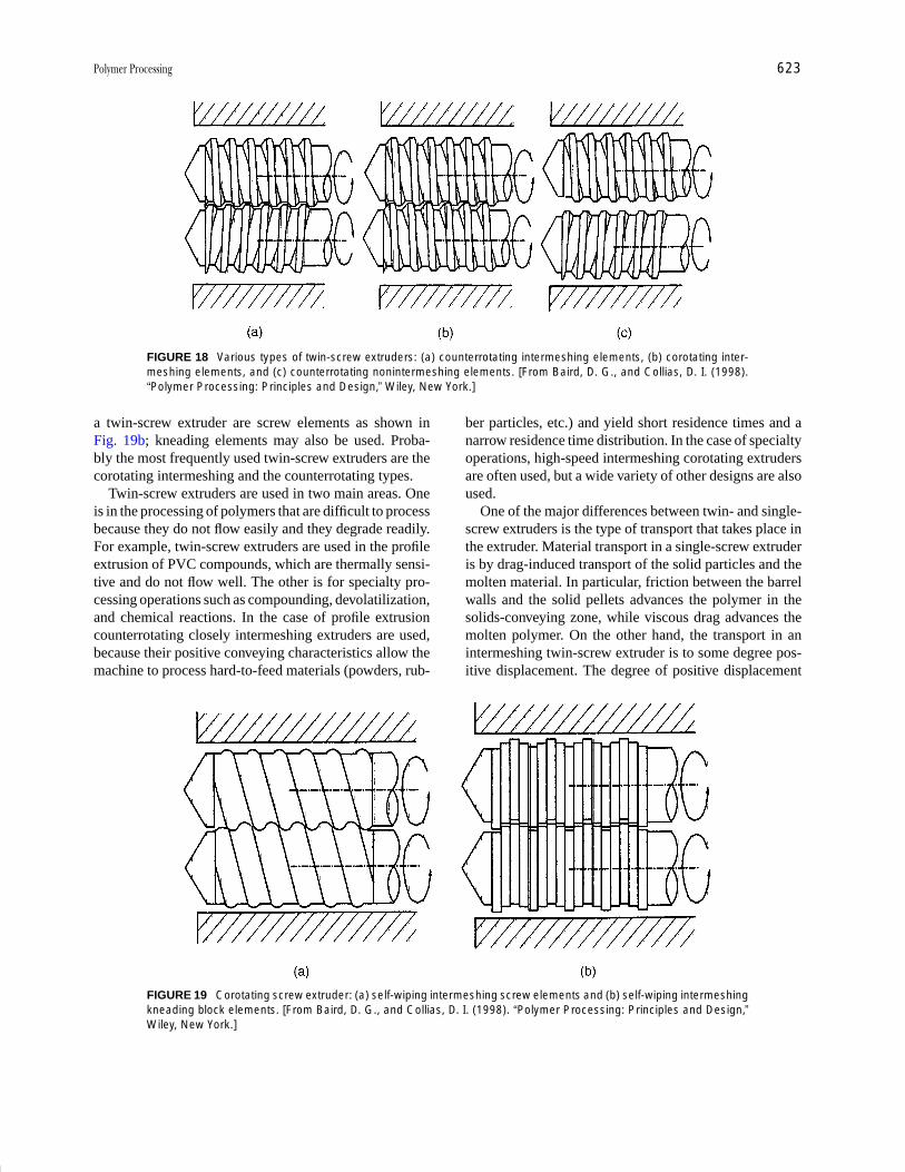
P1: FMX/LSU P2: GPB/GRD P3: GLQ Final pages
Encyclopedia of Physical Science and Technology EN012c-593 July 26, 2001 15:56
Polymer Processing 623
FIGURE 18 Various types of twin-screw extruders: (a) counterrotating intermeshing elements, (b) corotating inter-meshing elements, and (c) counterrotating nonintermeshing elements. [From Baird, D. G., and Collias, D. I. (1998).“Polymer Processing: Principles and Design,” Wiley, New York.]
a twin-screw extruder are screw elements as shown inFig. 19b; kneading elements may also be used. Proba-bly the most frequently used twin-screw extruders are thecorotating intermeshing and the counterrotating types.
Twin-screw extruders are used in two main areas. Oneis in the processing of polymers that are difficult to processbecause they do not flow easily and they degrade readily.For example, twin-screw extruders are used in the profileextrusion of PVC compounds, which are thermally sensi-tive and do not flow well. The other is for specialty pro-cessing operations such as compounding, devolatilization,and chemical reactions. In the case of profile extrusioncounterrotating closely intermeshing extruders are used,because their positive conveying characteristics allow themachine to process hard-to-feed materials (powders, rub-
FIGURE 19 Corotating screw extruder: (a) self-wiping intermeshing screw elements and (b) self-wiping intermeshingkneading block elements. [From Baird, D. G., and Collias, D. I. (1998). “Polymer Processing: Principles and Design,”Wiley, New York.]
ber particles, etc.) and yield short residence times and anarrow residence time distribution. In the case of specialtyoperations, high-speed intermeshing corotating extrudersare often used, but a wide variety of other designs are alsoused.
One of the major differences between twin- and single-screw extruders is the type of transport that takes place inthe extruder. Material transport in a single-screw extruderis by drag-induced transport of the solid particles and themolten material. In particular, friction between the barrelwalls and the solid pellets advances the polymer in thesolids-conveying zone, while viscous drag advances themolten polymer. On the other hand, the transport in anintermeshing twin-screw extruder is to some degree pos-itive displacement. The degree of positive displacement
P1: FMX/LSU P2: GPB/GRD P3: GLQ Final pages
Encyclopedia of Physical Science and Technology EN012c-593 July 26, 2001 15:56
624 Polymer Processing
depends on how well the flight of one screw closes theopposing channel of the other screw. Closely intermesh-ing counterrotating twin screw extruders provide the mostpositive displacement. However, some leakage will occur,which will reduce the degree of positive conveying thatcan be achieved. Counterrotating self-wiping twin-screwextruders actually operate in a mode similar to that of asingle-screw extruder. However, because elements can beeasily interchanged in a twin-screw extruder, it is possibleto change the channel depth profile and add more mixingelements.
The flow of material in twin-screw extruders is verycomplex, and the flow patterns are difficult to predict math-ematically. For this reason the simulation of processes intwin-screw extruders is not as well developed as it is forsingle-screw extruders. It is, therefore, difficult to pre-dict the performance of a twin-screw extruder based ongeometrical features, polymer properties, and processingconditions. Hence, it is difficult to carry out accurate de-sign calculations. For this reason twin-screw extruders areconstructed in modules in which the screw and barrel ele-ments can be changed. The screw design can be changedby changing the sequence of the screw elements. Hence,much of the design of twin-screw extruders is done onan empirical basis. One can use a combination of screwelements and kneading blocks to accomplish a given op-eration.
The sizes of twin-screw extruders range from 25 to244 mm (this is the diameter of one of the barrels). Thebarrel length to diameter ratio, L/D, ranges from 39 to 48.The length can be altered as required for most twin-screwextruders because of their modular construction.
V. COMPOUNDING
Polymers are rarely used in neat form but usually in thepresence of other additives. These additives may be inthe form of other polymers, processing aids, stabilizers,colarants, fillers, etc. The process by which additives arecombined with polymers is called compounding. Funda-mental principles of mixing are described briefly followedby commercial techniques used for compounding, andthen a description is given of some types of additives thatinfluence processibility and to some degree properties.
A. Principles of Mixing
The term mixing refers to operations that have a tendencyto reduce nonuniformities or gradients in concentration,temperature, size of a dispersed phase, or other propertiesof materials. Equivalently, a mixing operation increasesthe configurational entropy of the system, which reaches
a maximum as the configuration becomes random. Mixingis considered to be one of the most widespread industrialunit operations, and it is found in the core of many areasin the general industry. This unit operation might be aprocess in itself or it might be part of a more extendedsequence of processes.
In this article we will restrict ourselves to the study ofthe mixing of two-component systems. The two compo-nents are defined as either major or minor components bythe level of their total concentration. The goal of the mix-ing process is usually to achieve a homogeneous disper-sion of the minor component into the major one obtainingthe ultimate particle or subdivision (or volume element)level of the minor component. The above term is used ina restricted sense, because in its general form the ultimateparticle is the molecule and ultimate mixing is molec-ular mixing. However, in typical mixing operations thetwo parameters that define the size and form of the ulti-mate particle are the form of the component and the levelof satisfaction of the final dispersion. For example, in themixing of carbon black agglomerates in polyethylene (PE)the ultimate particle is one particle of carbon black definedby the form of the initial agglomerates (many particles to-gether) as well as by the satisfactory dispersion level of onecarbon black particle. In general, typical ultimate particlesare molecules and colloidal and microscopic particles.
Mixing is accomplished by movement of material fromvarious parts by the flow field. This movement occurs by acombination of the following mechanisms, two of whichare hydrodynamic and one is molecular. The first is con-vective transport. It is present in both laminar and turbu-lent regimes, and it can also be called “bulk diffusion.”Generally speaking, a colored pigment being dispersed ina bucket of paint is an example of laminar mixing. In thiscase, layers of pigment are thinned, lumps are flattened,and threads are elongated by laminar convective flow. Stir-ring of cream in a cup of coffee is an example of turbulentmixing, in which the mechanism of turbulent bulk flowpredominates at the first stages.
The second mechanism is eddy diffusion which is pro-duced by local turbulent mixing. This mechanism prevailsat the later stages in the example of the stirring of creaminto a cup of coffee mentioned above. The turbulent ed-dies in the flow field create small-scale mixing, which issometimes thought to be analogous to molecular diffusion.However, eddy diffusivity is much higher than moleculardiffusivity, and it occurs over longer length scales. Forgases and low-viscosity liquid systems eddy diffusion be-comes the usual mode of mixing.
Finally, there is molecular diffusion or interpenetrationof molecular species. It is responsible for the ultimate ho-mogenization on a molecular scale (the ultimate particlesare the molecules), and it is considered to be true
P1: FMX/LSU P2: GPB/GRD P3: GLQ Final pages
Encyclopedia of Physical Science and Technology EN012c-593 July 26, 2001 15:56
Polymer Processing 625
mixing. This diffusion is driven by the chemical potentialdifference due to concentration variation, and it is a veryslow process, because its timescale is proportional to thevalue of the diffusion coefficient. Thus, this mechanismbecomes important in gases and low molecular weight,miscible liquid systems, although there are timescale dif-ferences in those two cases.
The major difference between mixing in general and inpolymer processing stems from the fact that the viscosityof polymer melts is usually higher than 102 Pa sec, and thusmixing takes place in the laminar regime only (Re < 2000;to achieve such a number the polymer would have to flowdown a 1-m-wide channel at a velocity of 20 cm/sec). Thishas a severe consequence: the lack of eddy and molecu-lar diffusion, which greatly enhance the rate of mixingand reduce the scale of homogenization. Thus, all mixingtheories and practices should be adjusted to the laminarregime to find applicability in the polymer processing area.This remark applies also to solid–solid mixing in polymerprocessing, but it does not find application to the additionof low-molecular-weight substances into polymers, likedyes, where molecular diffusion plays a role.
Two basic types of mixing can be identified as exten-sive and intensive mixing. Distributive, convective, repet-itive, simple mixing, and blending are the main namesthat extensive mixing is also associated with, whereascompounding, dispersive, and dispersing mixing are thecorresponding names associated with intensive mixing.Extensive mixing refers to processes that reduce thenonuniformity of the distribution (viewed on a scale largerthan the size of the distributed components) of the minorinto the major component without disturbing the initialscale of the minor component. It can be achieved throughtwo mechanisms: rearrangement and deformation in lami-nar flow. Also, deformation achieved in shear, elongation,and squeezing flows plays a major role in distributing theminor component.
The term intensive mixing refers to processes that breakdown the liquid dispersed phase or the initial particle ag-glomerates, and they decrease the ultimate particle of thedispersion. A typical example is the dispersion of agglom-erates of colloidal carbon black particles in PE. In this casethe initial ultimate particle is the agglomerate, and the finalis the particle itself. Another example is the dispersion ofa polymer into another polymer where the minor compo-nent should be dispersed into small droplets or elongatedfibers (both of them have a length scale of about 10 µm).The analysis of dispersive mixing follows the lines of theanalysis of the distributive mixing with the complicationthat the breakup forces should now be included.
The geometry of the mixing equipment; physical pa-rameters such as viscosity, density, interfacial tension,elasticity, and attractive forces for solids; and operating
conditions such as temperature, speed of rotating parts,flowing velocity, and residence time are the important fac-tors which determine the relative strengths of the mixingmechanisms. As a consequence, this relative strength af-fects the efficiency of mixing and the quality of the prod-uct. In almost all cases, both good distribution and gooddispersion are required. In some cases, only distributivemixing can be tolerated if the next step offers dispersivecharacteristics and, respectively, dispersive mixing is usedwhen a finely dispersed mixture is required and when thenext step does not offer any dispersion characteristics.
Some of the nomenclature mentioned above gets a spe-cific connotation when referred to polymer processing,and thus we will give here some specific definitions. Com-pounding refers to the process of softening, melting, andcompaction of the polymer matrix and dispersion of theadditive into that matrix. Blending refers to all processes inwhich two or more components are intermingled withoutsignificant change of their physical state. Finally, knead-ing refers to mixing achieved by compression and foldingof layers over one another; milling refers to a combinationof smearing, wiping, and possibly grinding, and mullingrefers to wiping and rolling actions.
Dispersive mixing is the term used to describe mixingassociated with some fundamental change of the physicalcharacteristics of one or more of the components of themixture. Generally, dispersive mixing is divided into twoparts: The first part is the incorporation of the additivesin terms of agglomerated particles or the second polymercomponent into the polymer matrix, and the second part isthe dispersion (or deagglomeration) of the second phase toyield the final product. The microstructures of the blendsare determined by rheological, hydrodynamic, and ther-modynamic parameters. The rheological parameters areviscosity, elasticity, and yield stress of all components.The hydrodynamic parameters determine the flow fields.The thermodynamic parameters are related to solubility,adhesion, and diffusion of all components.
This type of dispersion has been applied in the polymerprocessing industry for at least 50 years. It is concernedwith the incorporation and deagglomeration of additivesin the polymer matrix with the ultimate goal being thereduction of the price or the improvement of the proper-ties of the final product. Of course, if the additive existsin the form of isolated noninteracting particles then thetask of mixing is only to distribute these particles uni-formly throughout the final product. However, when theadditive exists in the form of clusters of particles (interact-ing or noninteracting), then dispersive mixing ensures thatthe agglomerates break into isolated particles, which thenshould be distributed by extensive mixing mechanisms.
The size of the particles as well as their ability to in-teract with each other characterize the type of cluster as
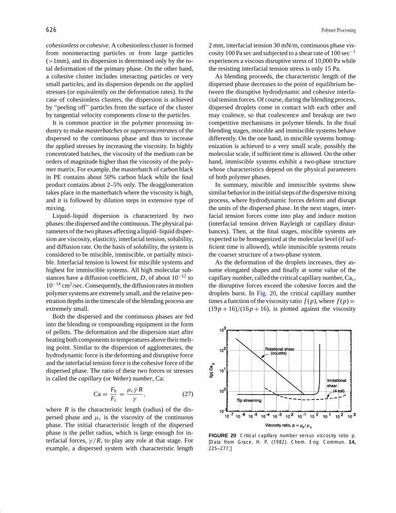
P1: FMX/LSU P2: GPB/GRD P3: GLQ Final pages
Encyclopedia of Physical Science and Technology EN012c-593 July 26, 2001 15:56
626 Polymer Processing
cohesionless or cohesive. A cohesionless cluster is formedfrom noninteracting particles or from large particles(>1mm), and its dispersion is determined only by the to-tal deformation of the primary phase. On the other hand,a cohesive cluster includes interacting particles or verysmall particles, and its dispersion depends on the appliedstresses (or equivalently on the deformation rates). In thecase of cohesionless clusters, the dispersion is achievedby “peeling off” particles from the surface of the clusterby tangential velocity components close to the particles.
It is common practice in the polymer processing in-dustry to make masterbatches or superconcentrates of thedispersed to the continuous phase and thus to increasethe applied stresses by increasing the viscosity. In highlyconcentrated batches, the viscosity of the medium can beorders of magnitude higher than the viscosity of the poly-mer matrix. For example, the masterbatch of carbon blackin PE contains about 50% carbon black while the finalproduct contains about 2–5% only. The deagglomerationtakes place in the masterbatch where the viscosity is high,and it is followed by dilution steps in extensive type ofmixing.
Liquid–liquid dispersion is characterized by twophases: the dispersed and the continuous. The physical pa-rameters of the two phases affecting a liquid–liquid disper-sion are viscosity, elasticity, interfacial tension, solubility,and diffusion rate. On the basis of solubility, the system isconsidered to be miscible, immiscible, or partially misci-ble. Interfacial tension is lowest for miscible systems andhighest for immiscible systems. All high molecular sub-stances have a diffusion coefficient, D, of about 10−12 to10−14 cm2/sec. Consequently, the diffusion rates in moltenpolymer systems are extremely small, and the relative pen-etration depths in the timescale of the blending process areextremely small.
Both the dispersed and the continuous phases are fedinto the blending or compounding equipment in the formof pellets. The deformation and the dispersion start afterheating both components to temperatures above their melt-ing point. Similar to the dispersion of agglomerates, thehydrodynamic force is the deforming and disruptive forceand the interfacial tension force is the cohesive force of thedispersed phase. The ratio of these two forces or stressesis called the capillary (or Weber) number, Ca:
Ca = Fh
Fc= µc γ R
γ, (27)
where R is the characteristic length (radius) of the dis-persed phase and µc is the viscosity of the continuousphase. The initial characteristic length of the dispersedphase is the pellet radius, which is large enough for in-terfacial forces, γ /R, to play any role at that stage. Forexample, a dispersed system with characteristic length
2 mm, interfacial tension 30 mN/m, continuous phase vis-cosity 100 Pa sec and subjected to a shear rate of 100 sec−1
experiences a viscous disruptive stress of 10,000 Pa whilethe resisting interfacial tension stress is only 15 Pa.
As blending proceeds, the characteristic length of thedispersed phase decreases to the point of equilibrium be-tween the disruptive hydrodynamic and cohesive interfa-cial tension forces. Of course, during the blending process,dispersed droplets come in contact with each other andmay coalesce, so that coalescence and breakup are twocompetitive mechanisms in polymer blends. In the finalblending stages, miscible and immiscible systems behavedifferently. On the one hand, in miscible systems homog-enization is achieved to a very small scale, possibly themolecular scale, if sufficient time is allowed. On the otherhand, immiscible systems exhibit a two-phase structurewhose characteristics depend on the physical parametersof both polymer phases.
In summary, miscible and immiscible systems showsimilar behavior in the initial steps of the dispersive mixingprocess, where hydrodynamic forces deform and disruptthe units of the dispersed phase. In the next stages, inter-facial tension forces come into play and induce motion(interfacial tension driven Rayleigh or capillary distur-bances). Then, at the final stages, miscible systems areexpected to be homogenized at the molecular level (if suf-ficient time is allowed), while immiscible systems retainthe coarser structure of a two-phase system.
As the deformation of the droplets increases, they as-sume elongated shapes and finally at some value of thecapillary number, called the critical capillary number, Cac,the disruptive forces exceed the cohesive forces and thedroplets burst. In Fig. 20, the critical capillary numbertimes a function of the viscosity ratio f (p), where f (p) =(19p + 16)/(16p + 16), is plotted against the viscosity
FIGURE 20 Critical capillary number versus viscosity ratio p.[Data from Grace, H. P. (1982). Chem. Eng. Commun. 14,225–277.]
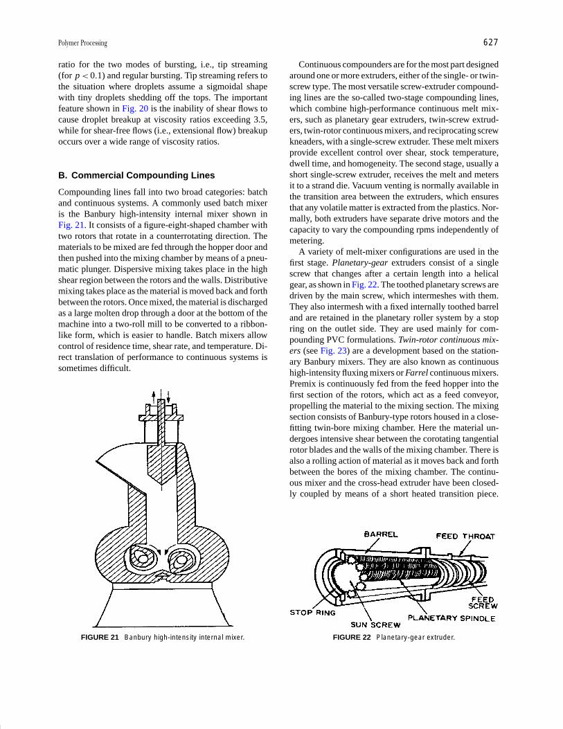
P1: FMX/LSU P2: GPB/GRD P3: GLQ Final pages
Encyclopedia of Physical Science and Technology EN012c-593 July 26, 2001 15:56
Polymer Processing 627
ratio for the two modes of bursting, i.e., tip streaming(for p < 0.1) and regular bursting. Tip streaming refers tothe situation where droplets assume a sigmoidal shapewith tiny droplets shedding off the tops. The importantfeature shown in Fig. 20 is the inability of shear flows tocause droplet breakup at viscosity ratios exceeding 3.5,while for shear-free flows (i.e., extensional flow) breakupoccurs over a wide range of viscosity ratios.
B. Commercial Compounding Lines
Compounding lines fall into two broad categories: batchand continuous systems. A commonly used batch mixeris the Banbury high-intensity internal mixer shown inFig. 21. It consists of a figure-eight-shaped chamber withtwo rotors that rotate in a counterrotating direction. Thematerials to be mixed are fed through the hopper door andthen pushed into the mixing chamber by means of a pneu-matic plunger. Dispersive mixing takes place in the highshear region between the rotors and the walls. Distributivemixing takes place as the material is moved back and forthbetween the rotors. Once mixed, the material is dischargedas a large molten drop through a door at the bottom of themachine into a two-roll mill to be converted to a ribbon-like form, which is easier to handle. Batch mixers allowcontrol of residence time, shear rate, and temperature. Di-rect translation of performance to continuous systems issometimes difficult.
FIGURE 21 Banbury high-intensity internal mixer.
Continuous compounders are for the most part designedaround one or more extruders, either of the single- or twin-screw type. The most versatile screw-extruder compound-ing lines are the so-called two-stage compounding lines,which combine high-performance continuous melt mix-ers, such as planetary gear extruders, twin-screw extrud-ers, twin-rotor continuous mixers, and reciprocating screwkneaders, with a single-screw extruder. These melt mixersprovide excellent control over shear, stock temperature,dwell time, and homogeneity. The second stage, usually ashort single-screw extruder, receives the melt and metersit to a strand die. Vacuum venting is normally available inthe transition area between the extruders, which ensuresthat any volatile matter is extracted from the plastics. Nor-mally, both extruders have separate drive motors and thecapacity to vary the compounding rpms independently ofmetering.
A variety of melt-mixer configurations are used in thefirst stage. Planetary-gear extruders consist of a singlescrew that changes after a certain length into a helicalgear, as shown in Fig. 22. The toothed planetary screws aredriven by the main screw, which intermeshes with them.They also intermesh with a fixed internally toothed barreland are retained in the planetary roller system by a stopring on the outlet side. They are used mainly for com-pounding PVC formulations. Twin-rotor continuous mix-ers (see Fig. 23) are a development based on the station-ary Banbury mixers. They are also known as continuoushigh-intensity fluxing mixers or Farrel continuous mixers.Premix is continuously fed from the feed hopper into thefirst section of the rotors, which act as a feed conveyor,propelling the material to the mixing section. The mixingsection consists of Banbury-type rotors housed in a close-fitting twin-bore mixing chamber. Here the material un-dergoes intensive shear between the corotating tangentialrotor blades and the walls of the mixing chamber. There isalso a rolling action of material as it moves back and forthbetween the bores of the mixing chamber. The continu-ous mixer and the cross-head extruder have been closed-ly coupled by means of a short heated transition piece.
FIGURE 22 Planetary-gear extruder.
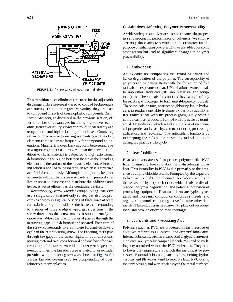
P1: FMX/LSU P2: GPB/GRD P3: GLQ Final pages
Encyclopedia of Physical Science and Technology EN012c-593 July 26, 2001 15:56
628 Polymer Processing
FIGURE 23 Twin-rotor continuous internal mixer.
This transition piece eliminates the need for the adjustabledischarge orifice previously used to control backpressureand mixing. Due to their great versatility, they are usedto compound all sorts of thermoplastic compounds. Twin-screw extruders, as discussed in the previous section, of-fer a number of advantages including high-power econ-omy, greater versatility, closer control of shear history andtemperature, and higher loading of additives. Corotatingself-wiping screws with mixing elements (i.e., kneadingelements) are used most frequently for compounding op-erations. Material is moved back and forth between screwsin a figure-eight path as it moves down the barrel. In ad-dition to shear, material is subjected to high extensionaldeformation in the region between the tip of the kneadingelement and the surface of the opposite element. A knead-ing action is applied to the material in which it is stretchedand folded continuously. Although mixing can take placein counterrotating twin screw extruders, it primarily re-lies on shear to disperse and distribute the additives and,hence, is not as efficient as the corotating devices.
Reciprocating-screw kneader compounding extrudersuse a single screw that not only rotates but also recipro-cates as shown in Fig. 24. A series of three rows of teethrun axially along the inside of the barrel, correspondingto a series of three wedge-shaped gaps per turn in thescrew thread. As the screw rotates, it simultaneously re-ciprocates. When the plastic material passes through thenarrowing gaps, it is deformed and sheared. Each turn ofthe screw corresponds to a complete forward–backwardcycle of the reciprocating screw. The kneading teeth passthrough the gaps in the screw flights in both directions,moving material two stops forward and one back for eachrevolution of the screw. As with all other two-stage com-pounding lines, the kneader stage is mated to an extruderprovided with a metering screw as shown in Fig. 24 fora Buss kneader system used for compounding of fiber-reinforced thermoplastics.
C. Additives Affecting Polymer Processability
A wide variety of additives are used to enhance the proper-ties and processing performance of polymers. We empha-size only those additives which are incorporated for thepurpose of enhancing processibility or are added for someother reason but lead to significant changes in polymerprocessibility.
1. Antioxidants
Antioxidants are compounds that retard oxidation andhence degradation of the polymer. The susceptibility ofpolymers to oxidation starts with the formation of freeradicals on exposure to heat, UV radiation, ozone, metal-lic impurities (from catalysts, raw materials, and equip-ment), etc. The radicals thus initiated have a high affinityfor reacting with oxygen to form unstable peroxy radicals.These radicals, in turn, abstract neighboring labile hydro-gens to produce unstable hydroperoxides plus additionalfree radicals that keep the process going. Only when anonradical inert product is formed will the cycle be termi-nated. Degradation, which results in the loss of mechani-cal properties and viscosity, can occur during processing,utilization, and recycling. The antioxidant functions byintercepting the radicals or preventing radical initiationduring the plastic’s life cycle.
2. Heat Stabilizers
Heat stabilizers are used to protect polymers like PVCfrom chemically breaking down and discoloring underheat. This instability in PVC is due primarily to the pres-ence of allylic chloride atoms. Prompted by the exposureto heat or UV light, the chemical breakdown results inthe release of hydrogen chloride, which leads to discol-oration, polymer degradation, and potential corrosion ofprocessing equipment. Heat stabilizers are typically or-ganic and inorganic compounds containing metals, andorganic compounds containing active functions other thanmetals. These stabilizers are known to plate out on equip-ment and have an effect on melt rheology.
3. Lubricants and Processing Aids
Polymers such as PVC are processed in the presence ofadditives referred to as internal and external lubricants.Internal lubricants, such as stearic acid or glycerol monori-cinoleate, are typically compatible with PVC and on melt-ing stay absorbed within the PVC molecules. They tendto lower the temperature at which the melt must be pro-cessed. External lubricants, such as low-melting hydro-carbons and PE waxes, tend to separate from PVC duringmelt processing and work their way to the metal surfaces.
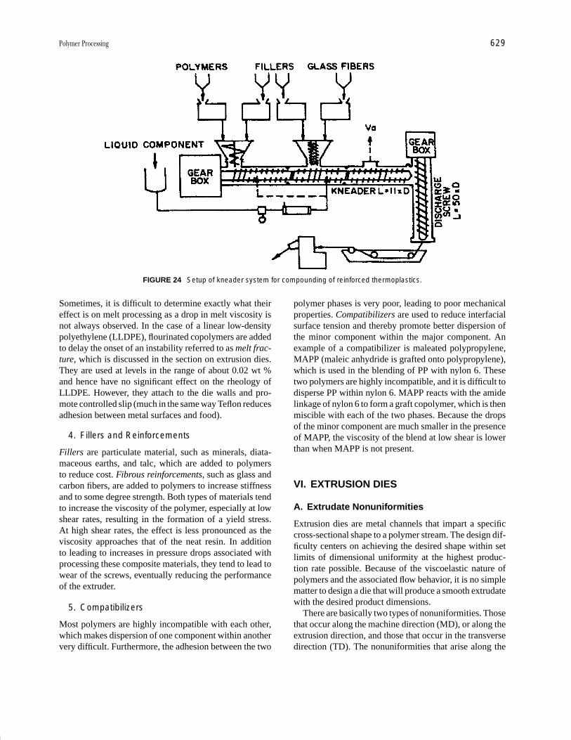
P1: FMX/LSU P2: GPB/GRD P3: GLQ Final pages
Encyclopedia of Physical Science and Technology EN012c-593 July 26, 2001 15:56
Polymer Processing 629
FIGURE 24 Setup of kneader system for compounding of reinforced thermoplastics.
Sometimes, it is difficult to determine exactly what theireffect is on melt processing as a drop in melt viscosity isnot always observed. In the case of a linear low-densitypolyethylene (LLDPE), flourinated copolymers are addedto delay the onset of an instability referred to as melt frac-ture, which is discussed in the section on extrusion dies.They are used at levels in the range of about 0.02 wt %and hence have no significant effect on the rheology ofLLDPE. However, they attach to the die walls and pro-mote controlled slip (much in the same way Teflon reducesadhesion between metal surfaces and food).
4. Fillers and Reinforcements
Fillers are particulate material, such as minerals, diata-maceous earths, and talc, which are added to polymersto reduce cost. Fibrous reinforcements, such as glass andcarbon fibers, are added to polymers to increase stiffnessand to some degree strength. Both types of materials tendto increase the viscosity of the polymer, especially at lowshear rates, resulting in the formation of a yield stress.At high shear rates, the effect is less pronounced as theviscosity approaches that of the neat resin. In additionto leading to increases in pressure drops associated withprocessing these composite materials, they tend to lead towear of the screws, eventually reducing the performanceof the extruder.
5. Compatibilizers
Most polymers are highly incompatible with each other,which makes dispersion of one component within anothervery difficult. Furthermore, the adhesion between the two
polymer phases is very poor, leading to poor mechanicalproperties. Compatibilizers are used to reduce interfacialsurface tension and thereby promote better dispersion ofthe minor component within the major component. Anexample of a compatibilizer is maleated polypropylene,MAPP (maleic anhydride is grafted onto polypropylene),which is used in the blending of PP with nylon 6. Thesetwo polymers are highly incompatible, and it is difficult todisperse PP within nylon 6. MAPP reacts with the amidelinkage of nylon 6 to form a graft copolymer, which is thenmiscible with each of the two phases. Because the dropsof the minor component are much smaller in the presenceof MAPP, the viscosity of the blend at low shear is lowerthan when MAPP is not present.
VI. EXTRUSION DIES
A. Extrudate Nonuniformities
Extrusion dies are metal channels that impart a specificcross-sectional shape to a polymer stream. The design dif-ficulty centers on achieving the desired shape within setlimits of dimensional uniformity at the highest produc-tion rate possible. Because of the viscoelastic nature ofpolymers and the associated flow behavior, it is no simplematter to design a die that will produce a smooth extrudatewith the desired product dimensions.
There are basically two types of nonuniformities. Thosethat occur along the machine direction (MD), or along theextrusion direction, and those that occur in the transversedirection (TD). The nonuniformities that arise along the
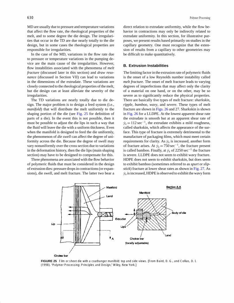
P1: FMX/LSU P2: GPB/GRD P3: GLQ Final pages
Encyclopedia of Physical Science and Technology EN012c-593 July 26, 2001 15:56
630 Polymer Processing
MD are usually due to pressure and temperature variationsthat affect the flow rate, the rheological properties of themelt, and to some degree the die design. The irregulari-ties that occur in the TD are due nearly totally to the diedesign, but in some cases the rheological properties areresponsible for irregularities.
In the case of the MD, variations in the flow rate dueto pressure or temperature variations in the pumping de-vice are the main cause of the irregularities. However,flow instabilities associated with the phenomena of meltfracture (discussed later in this section) and draw reso-nance (discussed in Section VII) can lead to variationsin the dimensions of the extrudate. These variations areclosely connected to the rheological properties of the melt,but die design can at least alleviate the severity of theirregularities.
The TD variations are nearly totally due to die de-sign. The major problem is to design a feed system (i.e.,manifold) that will distribute the melt uniformly to theshaping portion of the die (see Fig. 25 for definition ofparts of a die). In the event this is not possible, then itmust be possible to adjust the die lips in such a way thatthe fluid will leave the die with a uniform thickness. Evenwhen the manifold is designed to feed the die uniformly,the phenomenon of die swell can affect the degree of uni-formity across the die. Because the degree of swell mayvary nonuniformly over the cross section due to variationsin the deformation history, then the die lips (main shapingsection) may have to be designed to compensate for this.
Three phenomena are associated with the flow behaviorof polymeric fluids that must be considered in the designof extrusion dies: pressure drops in contractions (or expan-sions), die swell, and melt fracture. The latter two bear a
FIGURE 25 Film or sheet die with a coathanger manifold: top and side views. [From Baird, D. G., and Collias, D. I.(1998). “Polymer Processing: Principles and Design,” Wiley, New York.]
direct relation to extrudate uniformity, while the flow be-havior in contractions may only be indirectly related toextrudate uniformity. In this section, for illustrative pur-poses, we present results based primarily on studies in thecapillary geometry. One must recognize that the exten-sion of results from a capillary to other geometries maybe difficult to make quantitatively.
B. Extrusion Instabilities
The limiting factor in the extrusion rate of polymeric fluidsis the onset of a low Reynolds number instability calledmelt fracture. The onset of melt fracture leads to varyingdegrees of imperfections that may affect only the clarityof a material on one hand, or on the other, may be sosevere as to significantly reduce the physical properties.There are basically five types of melt fracture: sharkskin,ripple, bamboo, wavy, and severe. These types of meltfracture are shown in Figs. 26 and 27. Sharkskin is shownin Fig. 26 for a LLDPE. At the lowest apparent shear ratethe extrudate is smooth but at an apparent shear rate ofγa = 112 sec−1, the extrudate exhibits a mild roughness,called sharkskin, which affects the appearance of the sur-face. This type of fracture is extremely detrimental to themanufacture of packaging films, which must meet certainrequirements for clarity. As γa is increased, another formof fracture arises. At γa = 750 sec−1, the fracture presentis called bamboo. Finally, at γa of 2250 sec−1 the fractureis severe. LLDPE does not seem to exhibit wavy fracture.HDPE does not seem to exhibit sharkskin, but does seemto exhibit bamboo (sometimes referred to as spurt or slip-stick) fracture at lower shear rates as shown in Fig. 27. Asγa is increased, HDPE is observed to exhibit the wavy form

P1: FMX/LSU P2: GPB/GRD P3: GLQ Final pages
Encyclopedia of Physical Science and Technology EN012c-593 July 26, 2001 15:56
Polymer Processing 631
FIGURE 26 Different types of melt fracture exhibited by LLDPE with increasing apparent shear rate from left to right:smooth, sharkskin, bamboo or slip-stick, and gross. [From Baird, D. G., and Collias, D. I. (1998). “Polymer Processing:Principles and Design,” Wiley, New York.]
FIGURE 27 Different types of melt fracture exhibited by HDPE from left to right: smooth, slip-stick, wavy, and a formof gross fracture. [From Baird, D. G., and Collias, D. I. (1998). “Polymer Processing: Principles and Design,” Wiley,New York.]
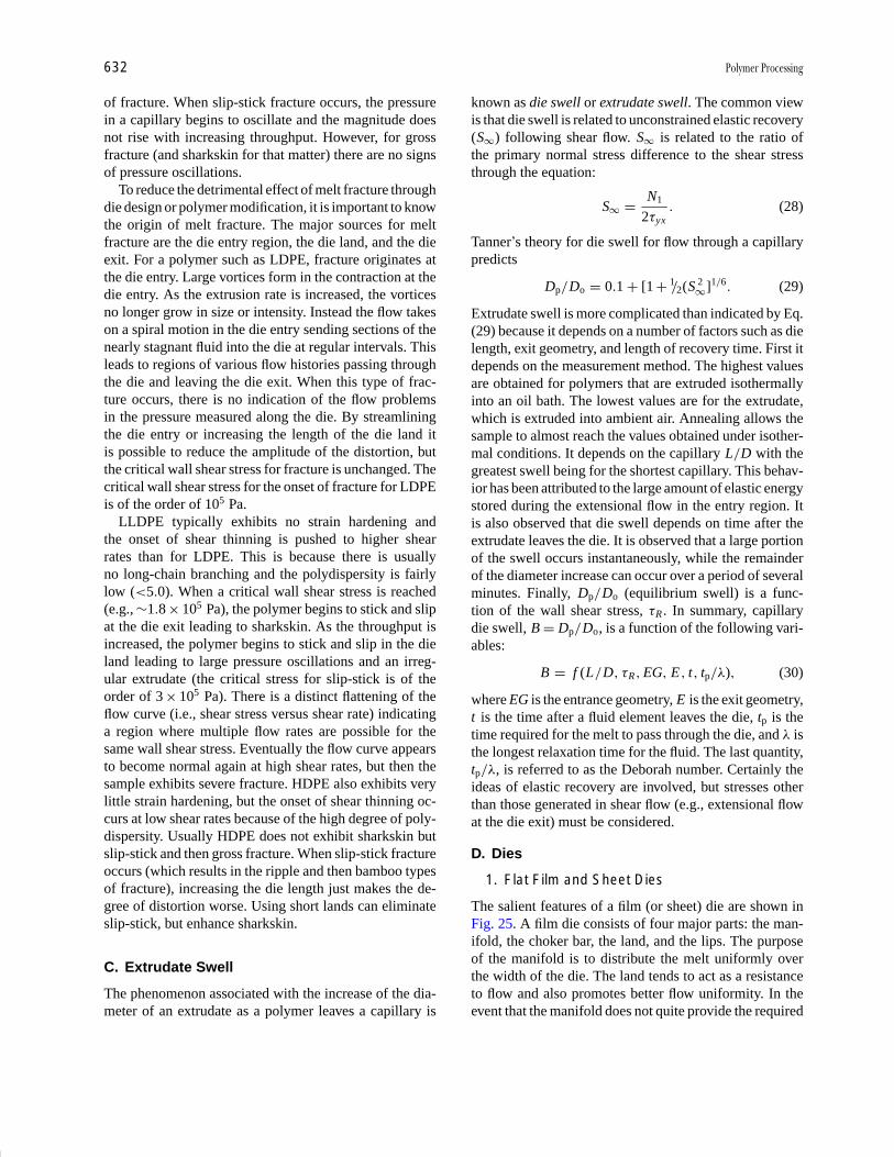
P1: FMX/LSU P2: GPB/GRD P3: GLQ Final pages
Encyclopedia of Physical Science and Technology EN012c-593 July 26, 2001 15:56
632 Polymer Processing
of fracture. When slip-stick fracture occurs, the pressurein a capillary begins to oscillate and the magnitude doesnot rise with increasing throughput. However, for grossfracture (and sharkskin for that matter) there are no signsof pressure oscillations.
To reduce the detrimental effect of melt fracture throughdie design or polymer modification, it is important to knowthe origin of melt fracture. The major sources for meltfracture are the die entry region, the die land, and the dieexit. For a polymer such as LDPE, fracture originates atthe die entry. Large vortices form in the contraction at thedie entry. As the extrusion rate is increased, the vorticesno longer grow in size or intensity. Instead the flow takeson a spiral motion in the die entry sending sections of thenearly stagnant fluid into the die at regular intervals. Thisleads to regions of various flow histories passing throughthe die and leaving the die exit. When this type of frac-ture occurs, there is no indication of the flow problemsin the pressure measured along the die. By streamliningthe die entry or increasing the length of the die land itis possible to reduce the amplitude of the distortion, butthe critical wall shear stress for fracture is unchanged. Thecritical wall shear stress for the onset of fracture for LDPEis of the order of 105 Pa.
LLDPE typically exhibits no strain hardening andthe onset of shear thinning is pushed to higher shearrates than for LDPE. This is because there is usuallyno long-chain branching and the polydispersity is fairlylow (<5.0). When a critical wall shear stress is reached(e.g., ∼1.8 × 10⁵ Pa), the polymer begins to stick and slipat the die exit leading to sharkskin. As the throughput isincreased, the polymer begins to stick and slip in the dieland leading to large pressure oscillations and an irreg-ular extrudate (the critical stress for slip-stick is of theorder of 3 × 10⁵ Pa). There is a distinct flattening of theflow curve (i.e., shear stress versus shear rate) indicatinga region where multiple flow rates are possible for thesame wall shear stress. Eventually the flow curve appearsto become normal again at high shear rates, but then thesample exhibits severe fracture. HDPE also exhibits verylittle strain hardening, but the onset of shear thinning oc-curs at low shear rates because of the high degree of poly-dispersity. Usually HDPE does not exhibit sharkskin butslip-stick and then gross fracture. When slip-stick fractureoccurs (which results in the ripple and then bamboo typesof fracture), increasing the die length just makes the de-gree of distortion worse. Using short lands can eliminateslip-stick, but enhance sharkskin.
C. Extrudate Swell
The phenomenon associated with the increase of the dia-meter of an extrudate as a polymer leaves a capillary is
known as die swell or extrudate swell. The common viewis that die swell is related to unconstrained elastic recovery(S∞) following shear flow. S∞ is related to the ratio ofthe primary normal stress difference to the shear stressthrough the equation:
S∞ = N1
2τyx. (28)
Tanner’s theory for die swell for flow through a capillarypredicts
Dp /Do = 0.1 + [1 + 1/2(S 2∞]1/6 . (29)
Extrudate swell is more complicated than indicated by Eq.(29) because it depends on a number of factors such as dielength, exit geometry, and length of recovery time. First itdepends on the measurement method. The highest valuesare obtained for polymers that are extruded isothermallyinto an oil bath. The lowest values are for the extrudate,which is extruded into ambient air. Annealing allows thesample to almost reach the values obtained under isother-mal conditions. It depends on the capillary L /D with thegreatest swell being for the shortest capillary. This behav-ior has been attributed to the large amount of elastic energystored during the extensional flow in the entry region. Itis also observed that die swell depends on time after theextrudate leaves the die. It is observed that a large portionof the swell occurs instantaneously, while the remainderof the diameter increase can occur over a period of severalminutes. Finally, Dp/Do (equilibrium swell) is a func-tion of the wall shear stress, τR . In summary, capillarydie swell, B = Dp/Do, is a function of the following vari-ables:
B = f (L/D, τR, EG, E, t, tp/λ), (30)
where EG is the entrance geometry, E is the exit geometry,t is the time after a fluid element leaves the die, tp is thetime required for the melt to pass through the die, and λ isthe longest relaxation time for the fluid. The last quantity,tp/λ, is referred to as the Deborah number. Certainly theideas of elastic recovery are involved, but stresses otherthan those generated in shear flow (e.g., extensional flowat the die exit) must be considered.
D. Dies
1. Flat Film and Sheet Dies
The salient features of a film (or sheet) die are shown inFig. 25. A film die consists of four major parts: the man-ifold, the choker bar, the land, and the lips. The purposeof the manifold is to distribute the melt uniformly overthe width of the die. The land tends to act as a resistanceto flow and also promotes better flow uniformity. In theevent that the manifold does not quite provide the required

P1: FMX/LSU P2: GPB/GRD P3: GLQ Final pages
Encyclopedia of Physical Science and Technology EN012c-593 July 26, 2001 15:56
Polymer Processing 633
uniformity in flow rate across the die width, the chokerbar can be used to adjust the flow rate locally. The die lipsprovide the final film thickness and can also be adjustedlocally to account for a nonuniform flow rate or nonuni-form die swell. The manifold design shown in Fig. 25is referred to as a coathanger. Other designs include theT-die and the fishtail die.
2. Annular Dies
Dies with annular cross sections are used to extrudepipes, tubes, tubular films, and parisons for blow molding.Center-fed dies are commonly used for extruding pipes,while side-fed dies are used for tubular films and parisons.The four basic annular die designs in use at the presenttime are shown in Fig. 28. These include (1) center-fedspider-supported mandrel dies, (2) center-fed screen packdies, (3) side-fed mandrel dies, and (4) spiral mandreldies. At the die exit there is usually an outer die ringthat forms the die land. Plastic pipes are primarily ex-truded using center-fed dies. The melt stream from theextruder passes from the circular opening to the annular
FIGURE 28 Four common annular die designs. [From Baird, D. G., and Collias, D. I. (1998). “Polymer Processing:Principles and Design,” Wiley, New York.]
die by means of the mandrel support tip. The melt thenpasses over the spider legs which support the mandrel, andthrough a converging annular region, which for pipes isusually 10◦ to 15◦. The converging region is followed byan annular region with parallel walls which imparts thefinal dimensions to the pipe. The outer diameter of thepipe can range from a few millimeters to approximately1.6 m. The ratio of the mandrel radius to outer wall ra-dius usually falls in the range of 0.8 to 0.925. The spiderlegs usually lead to problems in that not only are flowmarkings visible, but mechanically weak regions are gen-erated. These flow lines are also referred to as weld linesand are due to a higher degree of molecular orientationcaused by the high stresses imparted to the melt and theinability of the molecules to re-entangle during the timethe melt spends in the die. The strength of the weld lineis most likely related to the degree of re-entanglement ofthe molecules, which occurs as the melt passes throughthe die at the melt temperature. The re-entanglement timeappears to be much longer than the longest relaxationtime. It has been estimated from interrupted-shear exper-iments for polystyrene, for example, to be of the order
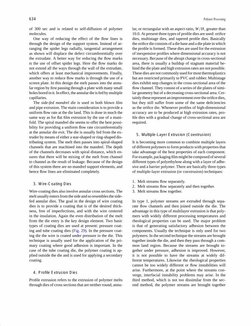
P1: FMX/LSU P2: GPB/GRD P3: GLQ Final pages
Encyclopedia of Physical Science and Technology EN012c-593 July 26, 2001 15:56
634 Polymer Processing
of 300 sec and is related to self-diffusion of polymermolecules.
One way of reducing the effect of the flow lines isthrough the design of the support system. Instead of ar-ranging the spider legs radially, tangential arrangementas shown will displace the defect circumferentially overthe extrudate. A better way for reducing the flow marksis the use of offset spider legs. Here the flow marks donot extend all the ways through the wall of the extrudate,which offers at least mechanical improvements. Finally,another way to reduce flow marks is through the use of ascreen plate. In this design the melt passes into the annu-lar region by first passing through a plate with many smallholes bored in it. In effect, the annular die is fed by multiplecapillaries.
The side-fed mandrel die is used in both blown filmand pipe extrusion. The main consideration is to provide auniform flow rate at the die land. This is done in much thesame way as for flat film extrusion by the use of a mani-fold. The spiral mandrel die seems to offer the best possi-bility for providing a uniform flow rate circumferentiallyat the annular die exit. The die is usually fed from the ex-truder by means of either a star-shaped or ring-shaped dis-tributing system. The melt then passes into spiral-shapedchannels that are machined into the mandrel. The depthof the channels decreases with spiral distance, which en-sures that there will be mixing of the melt from channelto channel as the result of leakage. Because of the designof this system there are no mandrel support elements, andhence flow lines are eliminated completely.
3. Wire-Coating Dies
Wire-coating dies also involve annular cross sections. Themelt usually enters from the side and so resembles the side-fed annular dies. The goal in the design of wire coatingdies is to provide a coating that is of the desired thick-ness, free of imperfections, and with the wire centeredin the insulation. Again the even distribution of the meltfrom the die entry is the key design element. Two basictypes of coating dies are used at present: pressure coat-ing and tube coating dies (Fig. 29). In the pressure coat-ing die the wire is coated under pressure in the die. Thistechnique is usually used for the application of the pri-mary coating where good adhesion is important. In thecase of the tube coating die, the polymer coating is ap-plied outside the die and is used for applying a secondarycoating.
4. Profile Extrusion Dies
Profile extrusion refers to the extrusion of polymer meltsthrough dies of cross sections that are neither round, annu-
lar, or rectangular with an aspect ratio, W/H , greater than10.0. At present three types of profile dies are used: orificedies, multistage dies, and tapered profile dies. Basicallythe orifice die consists of a die base and a die plate in whichthe profile is formed. These dies are used for the extrusionof inexpensive profiles where dimensional accuracy is notnecessary. Because of the abrupt change in cross-sectionalarea, there is usually a buildup of stagnant material be-hind the die plate and high extrusion rates are not possible.These dies are not commonly used for most thermoplasticsbut are restricted primarily to PVC and rubber. Multistagedies exhibit step changes in the cross-sectional area of theflow channel. They consist of a series of die plates of simi-lar geometry but of a decreasing cross-sectional area. Cer-tainly these represent an improvement over the orifice dies,but they still suffer from some of the same deficienciesas the orifice die. Whenever profiles of high-dimensionalaccuracy are to be produced at high extrusion rates, pro-file dies with a gradual change of cross-sectional area arerequired.
5. Multiple-Layer Extrusion (Coextrusion)
It is becoming more common to combine multiple layersof different polymers to form products with properties thattake advantage of the best properties of each component.For example, packaging film might be composed of severaldifferent types of polyethylene along with a layer of adhe-sive and a barrier polymer. There are basically three typesof multiple-layer extrusion (or coextrusion) techniques:
1. Melt streams flow separately.2. Melt streams flow separately and then together.3. Melt streams flow together.
In type 1, polymer streams are extruded through sepa-rate flow channels and then joined outside the die. Theadvantage in this type of multilayer extrusion is that poly-mers with widely different processing temperatures andrheological properties can be used. The major problemis that of generating satisfactory adhesion between thecomponents. Usually the technique is only used for twopolymers. In the second technique the streams are broughttogether inside the die, and then they pass through a com-mon land region. Because the streams are brought to-gether under pressure, adhesion is improved. However,it is not possible to have the streams at widely dif-ferent temperatures. Likewise the rheological propertiescannot be too widely different or flow instabilities willarise. Furthermore, at the point where the streams con-verge, interfacial instability problems may arise. In thethird method, which is not too dissimilar from the sec-ond method, the polymer streams are brought together

P1: FMX/LSU P2: GPB/GRD P3: GLQ Final pages
Encyclopedia of Physical Science and Technology EN012c-593 July 26, 2001 15:56
Polymer Processing 635
FIGURE 29 Two types of wire-coating processes: pressure and tube coating. [From Baird, D. G., and Collias, D. I.(1998). “Polymer Processing: Principles and Design,” Wiley, New York.]
in an adapter, and then they pass through a commondie. In this case the same die as that used for single-component extrusion can be used. Again the melt rheo-logical properties cannot be too dissimilar or an instabil-ity will arise that will disrupt the laminar nature of eachstream. However, this is one of the most inexpensive andsimplest methods for generating multiple-layer films andsheets.
Basically, two problems arise when trying to extrudemultiple layers of different fluids through the same die.First, if there are distinct viscosity differences betweenthe fluids, then the lower viscosity component will tryto encapsulate the higher viscosity component. Second,there are situations when the viscosities of two polymersare closely matched, but the interface still becomes wavyand distorted. This type of instability is thought to be due toslip at the interface between the two polymers. However,the most probable region for the onset of the instability
is at the die exit where large stresses arise as the velocityprofile undergoes a rapid rearrangement.
VII. POST-DIE PROCESSING
A. Fiber Spinning
A fiber is the fundamental unit of textiles, and it is definedas a material unit of axial length scale about 100 timesthe length scale in the cross direction (width or radius).There are two types of fibers: natural and synthetic (ormanmade). The term spinning has a different meaningfor natural and synthetic fibers. Spinning of natural fibersrefers to the twisting of short fibers into continuous lengths(also called filaments). On the other hand, spinning ofsynthetic fibers refers to production of continuous lengthsby any means. Finally, the yarn is made by twisting manyfilaments together.
P1: FMX/LSU P2: GPB/GRD P3: GLQ Final pages
Encyclopedia of Physical Science and Technology EN012c-593 July 26, 2001 15:56
636 Polymer Processing
The production of manmade fibers usually includes thefollowing processes:
1. Preparation of polymer (polymerization, chemicalmodification, etc.)
2. Preparation of the spinning fluid (polymer melt orsolution)
3. Spinning (extrusion, solidification, and deformationof the spinning line or filament)
4. Drawing (due to a higher linear speed at the take-uproll relative to that at the die; drawing is used toincrease the degree of molecular orientation andimprove the tensile strength, modulus of elasticityand elongation of the fibers)
5. Heat treatment6. Textile processing (twisting, oiling, dyeing, etc.).
The spinning process can be achieved mainly by threeprocedures: melt spinning, solution dry-spinning, and so-lution wet-spinning. Of these three procedures, melt spin-ning is the simplest and the most economical one. Itssimplicity stems from the fact that it involves only heattransfer and extensional deformation, whereas the othermethods in addition to the above processes involve alsomass transfer and diffusion. The melt spinning procedurecan be applied to polymers that are thermally stable at theextrusion temperature and that exhibit relatively high flu-idity at that temperature. Typical examples of melt-spunpolymers are polyamides, polyesters, polystyrene, poly-olefins, and inorganic glasses.
In the solution dry-spinning procedure the polymer isdissolved in a volatile solvent and the solution is extruded.Then the spinning line meets a stream of hot air and the sol-vent is evaporated. The recovery of the solvent increasesthe cost of the whole process. Typical examples of dry-spun polymers are cellulose acetate, acrylonitrile, vinylchloride, and acetate. Lately, extended-chain PE fibers(ECPE, Spectra fibers) are made by solution spinningin a typical melt-spinning apparatus. The solution wet-spinning procedure is applied to polymers that meet nei-ther criteria of the previous two methods (i.e., thermalstability and solubility in a volatile solvent). It involvesthe extrusion of a polymer solution into a liquid bath ofcoagulating agents, which drive the solvent out of the fil-ament. Four other spinning procedures (phase separationspinning, emulsion spinning, gel spinning, and reactionspinning) are not addressed here.
A schematic (not in scale) of the typical melt-spinningprocedure is shown in Fig. 30. Polymer is pumped bymeans of an extruder through a screen pack, in which thepolymer is filtered through layers of screens and sand.Then it is divided into many small streams by meansof a plate containing many small holes, the spinneret.
FIGURE 30 Schematic of the melt-spinning process for a singlefilament. [From Baird, D. G., and Collias, D. I. (1998). “PolymerProcessing: Principles and Design,” Wiley, New York.]
Some spinnerets can have as many as 10,000 holes (rayonspinning from a 15-cm platinum disk spinneret). Extru-sion through the spinneret (or die), subsequent die swell(due to the relaxation of the elastic stresses of the poly-mer), cooling of the filament by cooling air (or watervapor) flowing perpendicularly to the filament axis, so-lidification of the polymer, and its cold drawing in theregion from the solidification point to the take-up roll areshown in this figure. Part of the time the holes in thespinneret are circular in shape, but mostly they are ir-regular in shape. Typical shapes include trilobal, square,and cross. Note that dry- and wet-spinning from circu-lar spinneret holes usually results in irregularly shapedfibers.
In terms of the number of the filaments per spin-neret plate, as well as the spinning speed, melt spinningis divided into various groups. Monofilaments are pro-duced by one-hole spinneret plates, while most of thetime numerous filaments are extruded through the spin-neret (multifilament yarns). Very low-speed spinning, withspeeds ranging from 30 to 100 m/min, usually occursfor thick monofilaments spun through liquid baths. Low-speed spinning is usually carried out at speeds in the rangeof 100 to 750 m/min, where the filament tension is constantalong the entire length. To enhance the degree of orienta-tion and crystallinity and, hence, physical properties, theyarns are subsequently drawn and annealed and, there-fore, the melt-spinning process is considered to be a two-step process (first step: spinning; second step: drawing;
P1: FMX/LSU P2: GPB/GRD P3: GLQ Final pages
Encyclopedia of Physical Science and Technology EN012c-593 July 26, 2001 15:56
Polymer Processing 637
TSP). At intermediate speeds of 750 to 3500 m/min, thefilament tension is increased due to inertia and air drag.Finally, at high spinning speeds of 3500 m/min and abovepolymers such as PET undergo stress-induced crystalliza-tion. At high spinning speeds the structure, morphology,and resulting physical properties are somewhat differentfrom those obtained in conventional low-speed spinningprocesses.
Typical physical and mechanical properties of melt-spun fibers include the following: density, boil-off shrink-age, birefringence, tensile strength, percent elongation,modulus of elasticity, shrinkage tension, and dyeability.In practice, some of the above properties might be foundunder different names. Denier per filament (dpf; unit:denier, d) is usually substituted for density, and tenac-ity (unit: g-force/d or gf/d) is used in place of tensilestrength. Denier refers to the weight in grams of 9000 mof fiber and, hence, represents the linear density of thefiber.
B. Film Casting
A large activity of the polymer processing industry is theproduction of films and sheets of thermoplastic polymers.By definition, the term film is used for thicknesses less than250 µm (equal to about 0.010 in.), and the term sheet isused for thicker films. Note that in this section we will usethe term film generically, and we will occasionally men-tion the term sheet when confusion might occur. Theseproducts are primarily used in the packaging industry foreither foodstuffs (groceries, dairy produce, etc.) or otherconsumer products. Quite frequently, the properties of var-ious polymers need to be combined by either coating,lamination, or coextrusion. The major properties of thefilms and sheets are transparency, toughness, flexibility,and a very large aspect ratio (width or length to thickness)of about 103. Typical values of the thickness range fromabout 10 to 2500 µm, whereas the other two dimensionscan vary from 40 to 320 cm.
Flat film production consists mainly of the follow-ing three processes: extrusion, casting, and stabiliza-tion. Depending on the film thickness there are three majorgroups: fine film, with thicknesses of 10–50 µm; thickercast film and sheet, with thicknesses of 100–400 µm; andthermoformable sheet, with thicknesses of 200–2500 µm.The first two groups are produced on chrome-plated chill-roll or water-bath lines, whereas the third one is producedwith a special roll. All film types, after the chill-roll or wa-ter bath, are trimmed at the edges (some curling might oc-cur there) and either wound or undergo stretching (uniaxialor biaxial) or thermoforming. Polypropylene, polyethy-lene, polyester, and polyamide are the four most frequentlyused polymers on chill-roll lines.
C. Film Blowing
One method to produce film with a good balance of me-chanical properties is by extruding a polymer through afilm die and then subsequently stretching the film in twodirections as described in the previous section. The othertechnique involves extrusion through an annular die. Then,the moving tubular film is stretched and inflated by an airstream flowing from inside the annular die (the pressure isslightly higher than atmospheric pressure; Fig. 31) creat-ing a “bubble.” This bubble is cooled by an air jet flowingfrom an air ring toward its outside surface. The coolingresults in crystallization and solidification, which start atthe freeze line. Beyond this line the bubble boundariesbecome parallel to the centerline, and the polymer melt istransformed into a two-phase mixture consisting of moltenand solidified polymer. The frost line is the other bound-ary of the region that starts with the freeze line. Beyondthe frost line the deformation of the bubble is not verysignificant, and the bubble consists of one-phase materialonly, the solidified polymer. Thus, the bubble beyond thefreeze line is a constant radius cylinder. This cylinder isthen flattened by a set of guide rolls and taken up by aset of rubber nip rolls, which form an airtight seal at theupper end of the bubble. The takeoff at the nip rolls maybe either of constant speed or constant torque. Finally, thefilm is wound onto cylinders and sold as “lay-flat” tubingor trimmed at the edges and wound into two rolls of flat
FIGURE 31 Schematic of the film blowing process.

P1: FMX/LSU P2: GPB/GRD P3: GLQ Final pages
Encyclopedia of Physical Science and Technology EN012c-593 July 26, 2001 15:56
638 Polymer Processing
film. In terms of direction, most frequently this processtakes place vertically upward and less frequently verti-cally downward and horizontally. The major advantagesof this method over the first method are the economics andthe speed of production.
Film blowing and fiber spinning have general similar-ities. Both processes have free boundaries, and the flowsare predominantly elongational. They differ with respectto the orientation generated. The fiber spinning processimparts orientation in the axial direction only, whereasthe film blowing process imparts unequal (in general) bi-axial orientation. The two axes of orientation are the axial(machine; MD) direction due to the drawing of the tubeand the circumferential (nonmachine, or transverse; TD)direction due to the blowup of the tube. The mechanicalproperties of blown film are nearly uniform in both di-rections as a result of biaxial orientation, and this is thereason for producing flat film by the film blowing process.
The two main parameters of this process are the blowratio (or blow-up ratio), BR (or BUR), and the machine-direction draw (or drawdown) ratio, DR . The blow ratiois defined as the ratio of the final tube radius, Rf, to theinitial tube outside radius just downstream of the annulardie, R0:
BR = Rf
R0. (31)
Similarly, the draw ratio is defined as
DR = V
v0, (32)
where V is the takeup speed, and v0 is the die extrusionrate. The final film thickness, Hf, can be calculated fromthe blow and draw ratios and the mass conservation equa-tion as follows:
Hf = H0
BR DR; (33)
where H0 is the initial film thickness or, equivalently,the die gap thickness. Typical parameters in the filmblowing process are H0 = 1–2 mm R0 = 2.5–25 cm;v0 = 1–5cm/sec; BR = 1.5–5; DR = 5–25; �P = 50 Pa(i.e., the internal pressure is about 0.05% of the atmo-spheric pressure); and freeze-line height Z = 0.25–5 m.An average value of the blow and draw ratios and of theinitial film thickness yields a final film thickness on theorder of 50 µm (i.e., about 2 mils in English units). Interms of nomenclature, the final film is considered to bethick-gauge blown film whenever its thickness exceeds75 µm or equivalently 3 mils. In terms of applications,thick-gauge blown film is used in the production ofdunnage bags, heavy-duty shrink film, greenhouse film,lawn and garden bags, and resin and chemical packaging.
As far as the mechanical properties are concerned, thetear (test name: Elmendorf tear), impact (test name: dartdrop), and tensile strengths give an indication of the me-chanical strength of the tubular film. The amorphous aswell as the crystalline orientation development during theblowing process depend on the stretching imparted in themachine and transverse directions. Finally, besides orien-tation, the amount of crystallinity as well as the size of thecrystallites may play a significant role in the mechanicaland physical properties of the blown film.
This process is not as fast as fiber spinning, which re-sults in a more uniform temperature distribution in the filmrelative to that in the fiber. Usually, cooling is achieved byblowing an air stream from an axisymmetric air ring to-ward the external film surface. In some cases, in additionto the external air ring, an internal air cooling system isprovided. Finally, in some other cases, especially in thicktube and large bag production, cooling is achieved by awater spray or ring. Note that in the latter cases the filmmust be dried before winding up, which leads to an addi-tional step.
Commercially, the film blowing process is extensivelyused for the production of polyolefin (LDPE, HDPE, andPP) wrapping film. Mechanical strength, optical clarity,which depends on the degree and type of crystallinity forcrystallizable polymers, and the uniformity of thickness(variations of about 5% for films with a length scale of 10mm to 10 m is acceptable) are the three most importantand general properties of the film.
D. Stability
The rate of production in one of the three processing oper-ations just discussed, i.e., fiber spinning, film casting, andfilm blowing, is limited by the onset of instabilities. Twomajor types of instabilities are encountered in these pro-cesses. A significant degree of drawdown is used to reducethe fiber diameter or film thickness. If the stresses becometoo high, the polymeric material can fail by means of cohe-sive fracture. The filament or film merely ruptures. In thesecond type of instability, called draw resonance, the fiberdiameter begins to oscillate periodically when a criticaldrawdown ratio is reached. In the case of blown film, thisis manifested in variations in the film thickness leading tofluctuations in the bubble diameter. For Newtonian fluidsthe critical draw ratio for the onset of draw resonance, DRc,is about 20. For polymeric materials DRc is significantlylower with values of less than 5.0 observed. The type ofinstability depends on the nature of the polymer. Polymersthat exhibit strainhardening extensional viscosity (i.e., theextensional viscosity increases with increasing strain andstrain rate) such as LDPE tend to exhibit cohesive fracturebut not draw resonance, whereas polymers such LLDPE

P1: FMX/LSU P2: GPB/GRD P3: GLQ Final pages
Encyclopedia of Physical Science and Technology EN012c-593 July 26, 2001 15:56
Polymer Processing 639
that are not strain hardening are prone to draw resonance.In the case of film blowing, the bubble can also start aspiral motion due to the turbulent flow of the cooling airbeing emitted from the cooling ring at the base of the bub-ble. The instabilities are detrimental because they can beso severe as to cause the process to break down or at leastlead to variable mechanical properties.
VIII. MOLDING AND FORMING
A. Injection Molding
Injection molding is probably the most widely used cyclicprocess for manufacturing parts from thermoplastics. Inessence polymer pellets are plasticated in a single-screwextruder, and the molten polymer accumulates at the tip ofthe screw in a reservoir. The melt, which has accumulatedin the reservoir, is pushed forward by the screw whose dis-placement is controlled by hydraulic pressure. The meltflows through the nozzle, as shown in Fig. 32, which con-nects the extruder to the mold, passes through the sprue,along the runner, through the gate, and into the mold cav-ity. The sprue is designed to offer the least resistance toflow as possible while minimizing the amount of polymerthat is wasted. The runner is designed to carry melt to themold cavity, and when multiple cavities are involved, itmust be designed to ensure that each cavity fills at thesame time. The gate represents the entrance to the mold.Its location is of utmost importance to the appearance ofthe part. Furthermore, it is desirable to make the gate assmall as possible for not only cosmetic reasons but to facil-itate the separation of the part from the rest of the materialsolidified in the runner. The melt enters the mold cavitywhere it begins to solidify as it touches the mold wall. Assemicrystalline polymers solidify, they shrink as a resultof increases in density. Pressure is maintained during thecooling process to ensure that melt continues to flow intothe mold. Once solidification is complete, the mold plates
FIGURE 32 Schematic of the injection molding process.
FIGURE 33 Injection molding tooling showing the tip of the injec-tion system and its connection to the mold. [From Baird, D. G., andCollias, D. I. (1998). “Polymer Processing: Principles and Design,”Wiley, New York.]
open, and the part is ejected. While the screw is beingpulled back, it rotates plasticating more polymer.
The flow rate and pressure in the reservoir are shownschematically in Fig. 33. The injection pressure, which isthe hydraulic pressure applied to the screw, is one of thevariables that can be selected. Because of little resistanceto flow in the beginning, the flow rate through the nozzleis constant. However, as the melt advances through thesprue and runner, the resistance to flow increases, andthe pressure increases. As the cavity fills, the set pressurereaches a constant pressure (this is the injection pressureand is a machine setting), but the resistance to flowcontinues to increase. The flow rate through the nozzleas well as the flow rate into the cavity must decrease. Ifthe resistance to flow is too great either as a result of thepolymer solidifying or the melt viscosity being too high,the polymer will fail to fill the mold leading to what isknown as a short-shot. Once the mold fills, the hydraulicpressure applied to the screw is reduced (this is called theholding pressure) to a value which maintains enough flowof material into the mold to compensate for the volumechanges due to shrinkage. Some pressure is maintainedduring the complete cooling cycle.
In Fig. 34 the flow patterns in normal mold filling areshown schematically. As the melt leaves the gate, the frontis found to occupy various positions in the mold at differ-ent times. The velocity profiles in the fully developed flowbehind the front are shown in Fig. 34b. The flow well be-hind the front is primarily shear flow, while that at the frontinvolves stagnation flow. In essence, fluid passes throughthe center of the cavity to the front where it turns andthen is laid up on the wall of the mold where it solidifies.

P1: FMX/LSU P2: GPB/GRD P3: GLQ Final pages
Encyclopedia of Physical Science and Technology EN012c-593 July 26, 2001 15:56
640 Polymer Processing
FIGURE 34 Flow patterns in an end-gated mold: (a) top view of fronts as a function of time and (b) side view showingvelocity profiles and frontal region. [From Baird, D. G., and Collias, D. I. (1998). “Polymer Processing: Principles andDesign,” Wiley, New York.]
The velocity gradient, and hence stress, pass through amaximum at an interior point in the flow. A fluid ele-ment near the centerline will decelerate as it approachesthe front and become compressed along the flow directionand stretched along the transverse direction. The elementis then stretched further at the front and laid up on thewall where it is rapidly solidified in a highly oriented state.Hence, the extensional flow at the front stretches the fluidelement and leads to a higher degree of orientation in thematerial at the mold wall than at the interior of the material.
On occasion the opening at the gate is smaller than thecavity thickness, and the melt no longer fills the moldby an advancing front mechanism. Rather, it “snakes” itsway into the mold leading to a material with a poor surfaceappearance and reduced physical properties. Snaking doesnot seem to be a common method found in the filling ofmolds, but it can occur.
One of the major problems in injection molding of partsis the formation of weld lines, which lead to surface im-perfections and weak spots in the part. Weld lines arisefrom the presence of obstructions in the flow and fromthe impingement of advancing fronts from different gates.The former type of weld line is referred as a hot weld,while the latter is referred to as a cold weld. In the case ofthe hot weld the melt, the polymer stream is split by an ob-
struction such as a pin, for example, and then the streamsare brought back together. Usually the temperature at theinterface does not change much, and hence the streams arebrought back together at the processing temperature. Onthe other hand, when two fronts impinge on each other,the temperature of the free surfaces has dropped some-what, leading to the formation of what are called coldwelds.
B. Thermoforming
Thermoforming is used primarily for the manufactureof packaging and disposable containers. However, it isalso becoming a useful technique in the processing ofengineering thermoplastics to produce parts used in thetransportation industry. Polymers that are processed bythis technique must have sufficient melt strength that onheating they do not sag significantly under their ownweight, yet they can be deformed under pressure to takethe shape of a mold. Hence, highly crystalline polymerswith high melting temperatures and low molecular weightcannot be readily thermoformed. For example, nylon 6,6(TM = 265◦C and Mw = 30, 000) is not usually processedby means of thermoforming, while LDPE (TM = 110◦Cand Mw = 200, 000) is.
P1: FMX/LSU P2: GPB/GRD P3: GLQ Final pages
Encyclopedia of Physical Science and Technology EN012c-593 July 26, 2001 15:56
Polymer Processing 641
FIGURE 35 Plug-assisted vacuum thermoforming process.[From Baird, D. G., and Collias, D. I. (1998). “Polymer Processing:Principles and Design,” Wiley, New York.]
The essential features of the thermoforming process areshown in Fig. 35. Thermoplastic sheet is heated usuallyby means of radiation but sometimes in conjunction withconvection cooling to temperatures either just above Tg
in the case of amorphous polymers or Tm in the case ofsemicrystalline polymers. The exact temperature dependson the degree of sag exhibited by the material under its ownweight, which is determined by its rheological properties.The sample is then removed from the heating system andbrought into position over the mold. The sample is forcedto take the shape of the mold by applying pressure to thetop of the sheet or by generating a vacuum on the undersideof the sheet. The forming step occurs in the matter of asecond. The sample is maintained in the mold until it isrigid enough to be removed from the mold without alteringits shape.
There are a number of variations on the basic process.For example, in plug-assisted vacuum forming the heatedsheet is forced by a plug into the mold with the remainderof the shape being produced by the application of vac-uum to the underside of the sheet. This method is usedto help maintain a more uniform wall thickness through-out the part. Another example is matched-die molding.The heated sheet is forced to take the shape of the fe-male portion of the mold by the male part. This processis characterized by the formation of parts with more intri-cate shapes and uniform wall thickness. Finally, one lasttechnique is that of twin sheet thermoforming. Here twosheets are heated and then forced to take the shape of themold by applying air pressure on the inside of the sheetsand possibly vacuum on the outside. This process resem-
bles somewhat that of blow molding, which is discussednext. However, the sheets can be forced to take on dif-ferent shapes because each half of the mold can have adifferent shape. Furthermore, different polymers can beused for each half. The sheets must be held in the moldlong enough for bonding to occur.
Thermoforming can be divided into four sections: (1)sheet heating without deformation; (2) sheet stretchingwithout significant heat transfer; (3) part cooling in themold; and (4) postmolding operations such as trimming.The time to make a part is primarily determined by steps 1and 3 because these are of the order of minutes. However,the successful functioning of the part is determined by step2 because the distribution of wall thickness is determinedin this step.
C. Blow Molding
Blow molding is a process for generating hollow plasticarticles such as bottles and containers. This process wasinitially used by the packaging industry but more recentlyhas been used by the automotive industry to produce partssuch as fuel tanks, bumpers, dashboards, and seatbacks.In other words, plastic parts are being manufactured forapplications where some structural integrity is required.
Although a number of variations are possible in the wayin which blow molding is carried out, there are a numberof common steps. First, conventional melt processes areused to make a cylindrical tube (note: the preformed sam-ple may be of other shapes). When extrusion is used, thistube is referred to as a parison, and when injection mold-ing is used, it is referred to as a preform. The softenedpreformed tube is transferred to a mold consisting of twohalves, where it is sealed and inflated to assume the inter-nal contours of the mold. The part is cooled in the mold,until it reaches a temperature where it will maintain theshape of the mold when the mold is opened.
Extrusion blow molding is used frequently for polymersthat exhibit high melt strength such as polyolefins. Theprocess is shown schematically in Fig. 36. In this figurethe tubular parison is continuously extruded from a dieinto position between the two mold halves and then sepa-rated from the main stream by means of a knife. The moldcloses, sealing the end of the parison, and air pressure isapplied inflating the parison against the walls of the mold.The time for inflation is very short, usually in the rangeof a second depending on the size of the part. The longeststep in the process is the cooling of the part. The timefor cooling depends on the temperature to which the partmust be lowered to in order for it to maintain the shape ofthe mold and the rate of heat transfer between the moldwall and the part. The mold opens finally and the part isejected.

P1: FMX/LSU P2: GPB/GRD P3: GLQ Final pages
Encyclopedia of Physical Science and Technology EN012c-593 July 26, 2001 15:56
642 Polymer Processing
FIGURE 36 Blow-molding process. [From Baird, D. G., andCollias, D. I. (1998). “Polymer Processing: Principles and Design,”Wiley, New York.]
In some cases injection molding is used to generatepreforms rather than extrusion, but otherwise the processis nearly the same. Injection molding is used primarilywhen the screw-thread dimensions must be precise and toavoid flash, weld lines, and material waste at the base of thecontainer. Just as in the case of extrusion blow molding, itis possible to generate preforms with multiple layers forsituations where barrier properties are required.
In continuous processes the parison or preform musthave sufficient melt strength so that it does not sag underits own weight. Sagging leads to unacceptable variationsin the wall thickness of the part. For polymers such as PETit is usually not possible to use extrusion blow molding be-cause of severe sagging problems. To overcome saggingproblems, preforms are injection molded in a separate stepwhere they can be rapidly quenched to inhibit crystalliza-tion and, hence, remain clear. The preforms are then heatedby means of radiation to a temperature about 30◦C aboveTg, where cyrstallization kinetics are slow, but the materialis deformable. The heated preforms are then transferred tothe mold, where they are inflated by means of air pressure.
The process of inflating the parison is primarily oneof planar extensional flow especially away from the endsof the parsion. Because the ends of the parsion are con-strained as the parison expands, the thickness of the walldecreases as the diameter expands leading to primarilyplanar extensional deformation. For this reason the blowmolded part contains primarily orientation along the cir-cumferential or hoop direction and hence will exhibit me-chanical anisotropy.
To generate a better balance of mechanical properties itis necessary to create biaxial orientation in the part. Stretchblow molding is used to accomplish this. In essence theparison is stretched along the axial direction before beinginflated. Biaxial orientation is specifically required in largecontainers for fluids. For example, bottles for carbonatedbeverages are typically processed by means of stretch blowmolding.
D. Compression Molding
Compression molding is primarily used to process ther-mosetting systems and difficult to process thermoplastics,such as fiber-filled systems or thermoplastic elastomers.The essential features of the compression molding processare illustrated in Fig. 37. In the case of thermoplastics, apreheated mass of polymer, which may be either a sheetor a pile of pellets or powder, is placed in the mold. Thetemperature of the mold is set low enough to cause thepolymer to solidify but not so rapidly that it will not flow.Hydraulic pressure is applied to the top or bottom platepushing the plattens together. The molds are designed toprevent the top part of the mold from touching the bottompart, which would squeeze the resin from the mold.
The design of a compression molding process consistsof four aspects. The first is the selection of the properamount of material to fill the cavity when the mold halvesare closed. The second is determining the minimum time
FIGURE 37 Compression molding process. [From Baird, D. G.,and Collias, D. I. (1998). “Polymer Processing: Principles and De-sign,” Wiley, New York.]
P1: FMX/LSU P2: GPB/GRD P3: GLQ Final pages
Encyclopedia of Physical Science and Technology EN012c-593 July 26, 2001 15:56
Polymer Processing 643
required to heat the blank to the desired processing temper-ature and the selection of the appropriate heating technique(radiation heating, forced convection, etc.). It is necessaryto make sure that the center reaches the desired processingtemperature without the surface being held at too high of atemperature for too much time. The third is the predictionof the force required to fill the mold. Finally, the tempera-ture of the mold must be determined, keeping in mind thatone wants to cool the part down as rapidly as possible, buttoo rapid of a cooling rate will prevent the polymer fromfilling the mold.
E. Rotomolding
Rotomolding or rotational molding is a process for makinghollow plastic articles that cannot be easily produced bytechniques such as blow molding. Examples of objectsproduced by this method include underground storagetanks for fluids, playground equipment, and recreationalitems such as coolers and kyaks. The objects are usuallylarger and have thicker walls than can be handled in blowmolding. The process consists of placing polymer powder(typically 40 mesh or 500 µm in size) into a mold and thenplacing the mold into a forced convection oven where it isrotated around two axes to distribute the powder over themold walls. The polymer particles are fused into a solidmass by the process of sintering, which is governed bysurface tension and the polymer melt viscosity. High MIpolymers (i.e., low molar mass) are typically used becauseit is the viscosity that leads to the resistance of fusion ofthe particles. The part must be cooled slowly to ensuredimensional stability and minimize warpage. The process
is relatively slow taking in the range of an hour or more tomake a part. However, extremely large hollow objects canbe made this way (e.g., a storage tank having a length of20 ft and diameter of 8 ft). HDPE is most frequently used,but there are reports of nylons, ABS, and polycarbonatebeing used.
SEE ALSO THE FOLLOWING ARTICLES
ELASTICITY, RUBBERLIKE • PLASTICIZERS • POLYMERS,MECHANICAL BEHAVIOR • POLYMERS, RECYCLING •POLYMERS, THERMALLY STABLE • RHEOLOGY OF POLY-MERIC LIQUIDS
BIBLIOGRAPHY
Baird, D. G., and Collias, D. I. (1998). “Polymer Processing: Principlesand Design,” Wiley, New York.
Bird, R. B., Armstrong, R. C., and Hassager, O. (1987). “Dyna-mics of Polymeric Liquids. Volume I: Fluid Mechanics,” Wiley,New York.
Dealy, J. M., and Wissbrun, K. F. (1990). “Melt Rheology and Its Rolein Plastics Processing,” Van Nostrand Rheinhold, New York.
Green, E., ed. (2000). “Modern Plastics Encyclopedia,” McGraw-Hill,New York.
Michaeli, W. (1984). “Extrusion Dies,” Hanser, Munich.Morton-Jones, D. H. (1989). “Polymer Processing,” Chapman and Hall,
London.Rauwendall, C. (1986). “Polymer Extrusion,” Hanser, Munich.Rodriguez, F. (1996). “Principles of Polymer Systems,” Taylor and
Francis, Washington, DC.Van Krevelen, D. W. (1990). “Properties of Polymers,” Elsevier,
Amsterdam.

P1: GNH/MBS P2: GQT Final Pages Qu: 00, 00, 00, 00
Encyclopedia of Physical Science and Technology En012j-597 July 26, 2001 11:8
Polymers, Electronic PropertiesJ. MortXerox Corporation
I. ConductivityII. Electronic StatesIII. Triboelectricity and ElectretsIV. Piezo- and PyroelectricityV. Photoelectronic Properties of Pendant-Group
PolymersVI. Conducting Polymers: PolyacetyleneVII. σ -Bonded PolymersVIII. Applications
GLOSSARY
Amorphous Pertaining to a structurally disordered mate-rial in which the building blocks, atoms, or moleculesare randomly arranged without the periodicity charac-teristic of a crystalline solid.
Carrier range Distance an excess electronic carrier canmove in an applied field E before being immobilizedby trapping.
Chromophore Strictly speaking, a term denoting themolecular unit responsible for the color of amolecular solid but also used as a generic de-scription of a molecular unit such as a pendantgroup.
Conjugated polymer Polymer consisting of alternatingsingle and double bonds.
Electret Material in which real or polarization chargescan be stored for a long period of time.
Extended states Used synonymously with the term bandstates and describing a range of allowed energies,
originating from the condensed nature of a solid, forelectronic carriers.
Fermi level Parameter in quantum statistics defining theenergy of the highest occupied energy states.
Geminate recombination Recombination of photogen-erated electron–hole pairs before they ever become freeof their mutual Coulomb attractive field.
Mobility µ Critical parameter of electronic charge trans-port defined as the carrier velocity per unit field.
Molecular ion Charged molecular unit with either an ex-cess (anion) or deficit (cation) of electronic charge.
Pendant group Molecular unit attached to the polymerbackbone at an angle to the chain direction.
Piezoelectricity Change in electric polarization due toeither stress or strain.
Plasmon Collective excitation of free or bound carriers.Poling Technique for forming electrets involving the ap-
plication of a high electric field at an elevated tempera-ture followed by cooling to room temperature with thefield still applied.
645

P1: GNH/MBS P2: GQT Final Pages
Encyclopedia of Physical Science and Technology En012j-597 July 26, 2001 11:8
646 Polymers, Electronic Properties
Pyroelectricity Change in electric polarization due totemperature change.
Soliton As applied to conducting polymers, it refers toa bond alternation defect that results in a particlelikefield pattern.
Triboelectricity Transfer of charge between two solidsdue to their contact and separation.
A POLYMER SOLID is composed of a collection of verylong molecular chains that are characterized by strongchemical bonding within the chain and much weaker inter-chain bonding. In this sense, a polymer can be consideredto be an assembly of individual chains. Each chain cancontain a very large number (∼105 or more) of identicalsubunits bonded together. Each subunit can be viewed asa separate molecule with electronic states consisting ofthe molecular orbitals of the molecule. In describing theelectronic states of polymers, the degenerate molecularorbitals that overlap in a periodic fashion lift their degen-eracy by forming extended, that is, bands of, electronicstates. Thus, bonding and antibonding molecular orbitalslead to polymer valence and conduction bands, respec-tively. To this degree, polymers can be viewed as organicsemiconductors and, by analogy with the more familiarinorganic crystalline semiconductors such as silicon, theconcepts of energy band theory can be used to characterizetheir electronic states and properties.
I. CONDUCTIVITY
Polymers are a familiar part of everyday life and, becauseof the ability of chemists to tailor-make their properties,have found widespread application. Until recently, theseapplications capitalized on advantageous properties suchas chemical inertness and durability. By contrast, the mostvalued electrical property of polymers was their capacityto inhibit conductivity, that is, act as insulators, and lit-tle concerted work was done to examine and understandthe fundamentals in order to enhance electrical conduc-tivity in polymers. Beginning in the 1970s, a resurgenceof effort occurred in the study of polymers as electronicmaterials. This has been characterized by an interdisci-plinary approach involving physicists, chemists, materi-als scientists, and device engineers. This renewed interestwas stimulated by the interplay of scientific and techno-logical motivations. For the scientist, polymers posed newand often unconventional questions regarding the inter-pretation of experimental results. From the technologicalperspective, it was an explicit goal to explore the poten-tial for combining useful electronic functions of polymerswith their unique materials properties. Figure 1 shows the
FIGURE 1 Representative conductivities of polymers and in-organic materials. The asterisk denotes that these values areachieved in doped materials. [From Mort, J., and Pfister, G., eds.(1982). “Electronic Properties of Polymers,” Wiley, New York, bypermission.]
range of conductivities that have been reported in poly-mer materials compared with the more familiar inorganicmaterials.
This article provides a review of the development ofthis new area of solid-state science. Emphasis is placed onkey ideas, particularly as they contrast to more traditionalconcepts in the solid-state properties of crystalline or or-dered solids. Topics covered include electronic states inpolymers, an essential precursor to understanding the elec-tronic properties of polymers; charge storage; piezo- andpyroelectricity; photoconductivity and electronic trans-port in polymers (e.g., pendant-group polymers) wherelocalized molecular ion states play a determining role andin polymers (e.g., conjugated polymers) where delocal-ization of electronic charge is significant.
Finally, the actual and potential technological applica-tions and commercial use of polymers as electronic mate-rials are discussed. Particular stress is placed on how thecontrasting properties of the various types of polymersdetermine their advantage in specific applications.
II. ELECTRONIC STATES
It is convenient for the discussion of this aspect of poly-mers to consider separately two classes that have quite dif-ferent optical and electrical properties. The first consists

P1: GNH/MBS P2: GQT Final Pages
Encyclopedia of Physical Science and Technology En012j-597 July 26, 2001 11:8
Polymers, Electronic Properties 647
FIGURE 2 Examples of a saturated polymer (a) without pendantgroups, polyethylene, and (b) with a pendant group, poly(N-vinylcarbazole), and associated energy level picture.
of polymers with the bonds saturated (i.e., complete bondsatisfaction) or unsaturated but no pendant groups. Exam-ples of these are polyethylene and polyacetylene, respec-tively. The second class comprises polymers with satu-rated backbones with appended aromatic chromophoresthat project out of the polymer chain. Polystyrene andpoly(N -vinyl carbazole) (PVCA) are representative ex-amples. Figure 2 schematically represents examples ofthese two polymer classes together with the appropriateelectronic energy level picture. As alluded to above, thestrong intrachain covalent bonding leads to wide bandsof states with an energy gap, εg between the last-filledand first empty band. This is applicable even for amor-phous polymers because of the maintenance of periodic-ity in the chain direction. An important requirement forthe applicability of the band theory relates the strengthof any electron–phonon interaction with the width of theenergy band. In order for a carrier to remain within anenergy band of width W after a phonon-scattering event,the Heisenberg uncertainty principle states that Wτ > h,where τ is the electron–phonon scattering time. Sinceµ = eτ/m∗ (m∗ is the effective mass of the carrier), thenµ must be >he/m∗W . For reasonable choices of m∗, aminimum mobility of ∼0.2 cm2 V−1 sec−1 is required forthe valid application of band theory. This value is typicalof those experimentally measured for molecular crystalssuch as anthracene. By contrast, calculations for polyethy-lene and polyacetylene predict mobilities considerablyhigher than this minimum value and suggest that the con-
cepts of band theory may have validity for these poly-mers. These considerations are further amended if, as isthe case in reality, the polymer materials are not ordered asin single crystals. Any variation in the energy of a molec-ular orbital due to disorder (compositional, translational,or rotational) can impede band formation by the disrup-tion of the required periodicity. Experimental values formobilities in pendant-group polymers reveal values muchlower (∼10−4 cm2 V−1 sec−1 or less), which reflects theconsequences of strong electron–phonon interactions rel-ative to bandwidths together with substantial effects ofdisorder.
The conventional method of experimentally studyingelectronic states in polymers is that of optical absorption,including increasingly sophisticated techniques such aslow-energy electron-loss spectroscopy and synchrotronradiation source spectroscopy. These techniques allowsuch optical properties as absorption, reflectivity, and di-electric loss to be measured over an energy range from0.2 to 1000 eV with a resolution of 0.1 eV. With theseenergies, it is also possible to do core-level spectroscopyin which the very narrow deep-lying atomic levels, by act-ing as a source of electrons of well-defined energies, canbe used to probe the structure in the broader, higher ly-ing empty extended states. Photoemission spectroscopy,in which electrons are excited out of the polymer, cangive complementary information regarding filled-valencemolecular states.
A. Pendant-Group Polymers
The extension of the pendant group perpendicular tothe chain direction and its typically planar character canlead to very little overlap and therefore interaction evenbetween adjacent pendant groups. Amorphous pendant-group polymers are therefore similar to a random assemblyof isolated pendant molecules. This fact has several far-reaching consequences. The electronic states of pendant-group polymers bear a remarkable resemblance to thoseof the isolated pendant group. Similarly, the aromatic pen-dant groups give rise to electronic states in the gap betweenthe valence and conduction band and play a dominant rolein the static and dynamic electrical properties, as is dis-cussed in Sections III and V.
The most obvious feature of their electronic absorptionspectra is the close similarity to those of the effectivelyisolated chromophores, which can be observed in the gasphase. Figure 3 shows a typical energy-loss function andits derivative for polystyrene. The features indicated by thearrows, covering the range from 9 to 19 eV on the risingedge of the plasmon peak, correspond to strong peaks inthe ultraviolet absorption spectrum of benzene, which isclosely related to the styrene chromophore.
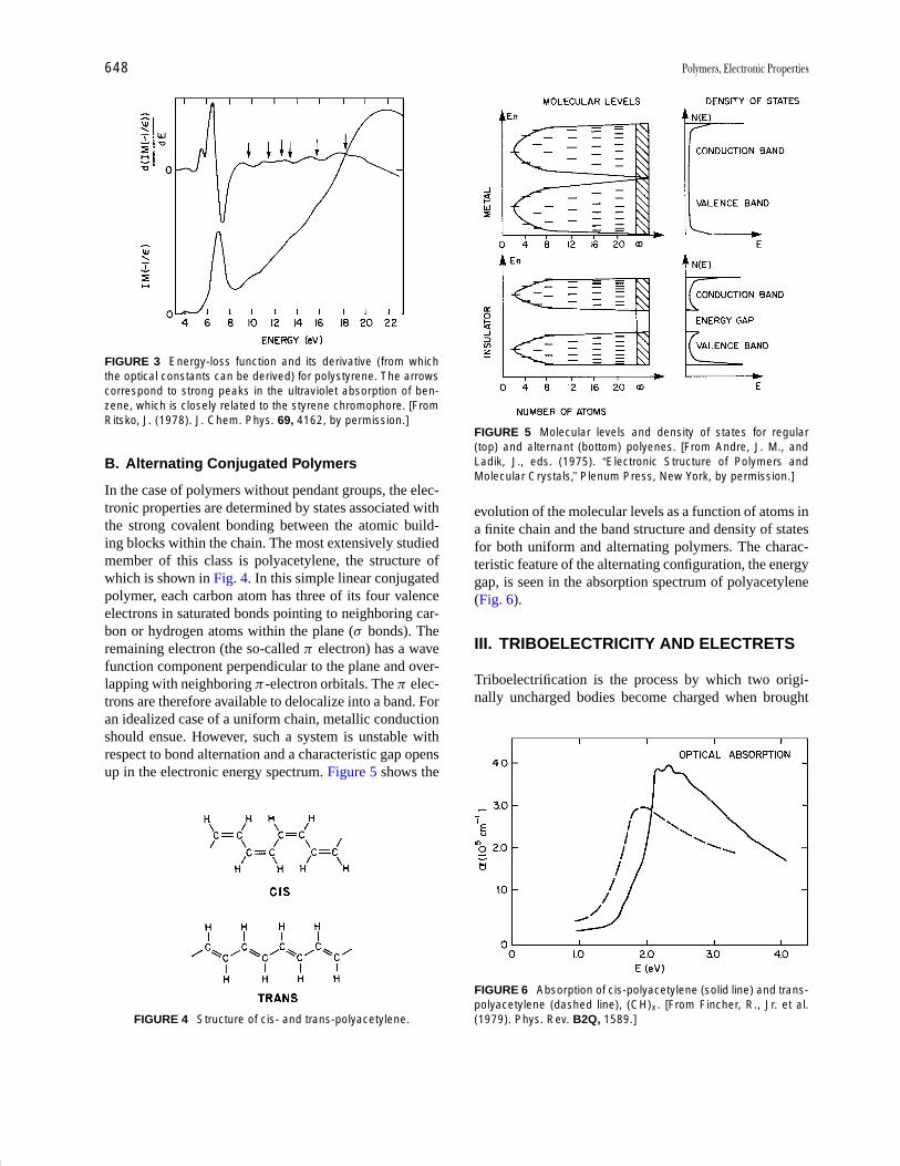
P1: GNH/MBS P2: GQT Final Pages
Encyclopedia of Physical Science and Technology En012j-597 July 26, 2001 11:8
648 Polymers, Electronic Properties
FIGURE 3 Energy-loss function and its derivative (from whichthe optical constants can be derived) for polystyrene. The arrowscorrespond to strong peaks in the ultraviolet absorption of ben-zene, which is closely related to the styrene chromophore. [FromRitsko, J. (1978). J. Chem. Phys. 69, 4162, by permission.]
B. Alternating Conjugated Polymers
In the case of polymers without pendant groups, the elec-tronic properties are determined by states associated withthe strong covalent bonding between the atomic build-ing blocks within the chain. The most extensively studiedmember of this class is polyacetylene, the structure ofwhich is shown in Fig. 4. In this simple linear conjugatedpolymer, each carbon atom has three of its four valenceelectrons in saturated bonds pointing to neighboring car-bon or hydrogen atoms within the plane (σ bonds). Theremaining electron (the so-called π electron) has a wavefunction component perpendicular to the plane and over-lapping with neighboring π -electron orbitals. The π elec-trons are therefore available to delocalize into a band. Foran idealized case of a uniform chain, metallic conductionshould ensue. However, such a system is unstable withrespect to bond alternation and a characteristic gap opensup in the electronic energy spectrum. Figure 5 shows the
FIGURE 4 Structure of cis- and trans-polyacetylene.
FIGURE 5 Molecular levels and density of states for regular(top) and alternant (bottom) polyenes. [From Andre, J. M., andLadik, J., eds. (1975). “Electronic Structure of Polymers andMolecular Crystals,” Plenum Press, New York, by permission.]
evolution of the molecular levels as a function of atoms ina finite chain and the band structure and density of statesfor both uniform and alternating polymers. The charac-teristic feature of the alternating configuration, the energygap, is seen in the absorption spectrum of polyacetylene(Fig. 6).
III. TRIBOELECTRICITY AND ELECTRETS
Triboelectrification is the process by which two origi-nally uncharged bodies become charged when brought
FIGURE 6 Absorption of cis-polyacetylene (solid line) and trans-polyacetylene (dashed line), (CH)x . [From Fincher, R., Jr. et al.(1979). Phys. Rev. B2Q, 1589.]

P1: GNH/MBS P2: GQT Final Pages
Encyclopedia of Physical Science and Technology En012j-597 July 26, 2001 11:8
Polymers, Electronic Properties 649
into contact and then separated. This process occurs for allhighly insulating materials, but its occurrence in polymershas enormous technical and commercial significance inelectrophotography and as the cause of troublesome staticelectricity. Triboelectricity is a particular case of the gen-eral phenomenon of charge storage exhibited by electrets.Polymers are capable of storing electrical charges for along period of time, if sufficiently insulating. The storedcharges may be real (i.e., net charge is added) or polariza-tion charges or a combination of both. The real chargesconsist of layers of positive or negative charges trapped ator near surfaces or distributed throughout the bulk (volumecharges). The real charges may also be inhomogeneouslylocated within molecular or domain structures resemblinga dipole polaization. True polarization charges result fromthe frozen-in alignment of dipoles that may be a conse-quence of molecular structure. This aspect, which pro-duces piezo- and pyroelectric properties, is discussed inSection IV. The permanence of charge storage in polymersdepends on conductivity, charge transport properties, andpolar relaxation frequencies. Since most of these proper-ties are thermally activated, the storage times are stronglytemperature dependent.
Triboelectrification or the formation of electrets (result-ing from real charges) can be understood only by consid-ering the band structure of polymers and, as an example, acontacting metal as a source of additional charges. Refer-ring to Fig. 7, it can be seen that if insulating polymers areviewed as wide-band-gap solids with no states within thegap then no charge transfer from the contacting metal canoccur. The fact that both triboelectrification and electretsare well known implies that, contrary to this simple view,states must exist essentially isoenergetic to the metal Fermi
FIGURE 7 Energy level diagram of a contact between a metaland an insulator with surface states. (a) Before contact, (b) aftercontact. φm and φp are the metal and polymer work functions, re-spectively; φc and φco represent the energy difference betweenthe polymer conduction band and the Fermi level after and be-fore contact, respectively. [From Mort, J., and Pfister, G., eds.(1982). “Electronic Properties of Polymers,” Wiley, New York, bypermission.]
level, thus enabling charge transfer to occur. These statescan be of two general types. The first are extrinsic surfacestates that occur only at the surface of the polymer. Unsat-urated defects, chain-end groups, adsorbed molecules, orchemically modified surfaces due to ambients or even ad-ditives introduced in the synthesis process are candidatesfor these extrinsic states (Fig. 7).
The second type of state is more fundamental, since itconsists of intrinsic bulk states. This is particularly trueof pendant-group polymers in which, as was discussedpreviously, the electronic states of the pendant group playa dominant role. For such materials, any excess chargeis localized on the individual pendant groups, formingmolecular ions. The energy of these electronic states issubject to large relaxation effects because of the strongelectron–phonon interaction between the excess chargeand the large degrees of freedom existing within the largeand easily deformable molecules. The extended or wideenergy bands associated with the saturated chain are sepa-rated by a wide band gap, while the molecular ion states as-sociated with the addition (anion) or withdrawal of an ex-cess electron (cation) lie within this gap. Inhomogeneousbroadening of these states occurs due to static polariza-tion fluctuations arising from the disordered amorphousnature of the polymer. In this picture, charge is transferredto polymer states localized in energy to within ∼0.4 eVof the Fermi level of the contacting metal. The sign of tri-boelectrification of the polymer depends on whether it isenergetically more favorable to add or withdraw an elec-tron. The occupied molecular ion state is presumed to behighly stable in that the transferred charge does not per-colate, due to its extreme localization, to empty states oflower energy. This question of localization of charge onpendant groups is of central importance in understandingthe motion of charge in molecular solids and is discussedfurther in Section V.
Many details remain unclear, not the least of which isthe consistency of experimental results. This is hardly sur-prising since both of these phenomena are controlled bydefect or impurity states and surface contamination canoverwhelm the other, more fundamental effects due to in-trinsic states. Nonetheless, the general features of the phe-nomena and their causes are now based on a picture thattakes into account the electronic energy level descriptionof polymers.
IV. PIEZO- AND PYROELECTRICITY
Piezo- and pyroelectricity are phenomena associated withthe stress and temperature dependence, respectively, ofremanent or frozen-in polarization. Although a numberof polymers possess these properties, none match the
P1: GNH/MBS P2: GQT Final Pages
Encyclopedia of Physical Science and Technology En012j-597 July 26, 2001 11:8
650 Polymers, Electronic Properties
magnitude of the effects in polyvinylidene fluoride(PVF2), which is the most widely studied and commer-cially used piezo- and pyroelectric polymer.
Substantial piezo- and pyroelectricity can be perma-nently induced by heating stretched films to ∼100◦C, fol-lowed by cooling to ambient temperature with a strongdc electric field (∼300 kV cm−1) applied. This treatmentis called “poling.” Such polarization, attributed to redis-tribution of electronic or ionic charges within the solidor injected from electrodes, characteristically vanishes onexceeding some polarization temperature, Tp. The effectin PVF2 is totally different in that the induced polariza-tion is thermally reversible and polarization currents areproduced on either heating or cooling.
Polyvinylidene fluoride is a crystalline polymer that ex-ists in at least three and possibly more crystalline phases.Since the polymorphism is a critical ingredient in deter-mining the piezo- and pyroelectric properties, it is worthyof some discussion. Phase I (β form) has a planar zigzagconformation and ordered C–F bonds, giving a large unitdipole of 2.1 debye (D). This large moment and the facilitywith which it can orient, because of the small atomic vol-ume of fluorine, accounts for the high permittivity. PhaseII (α form) has a conformation with two chains of oppositedipole moment per unit cell. Melt-crystallized samples be-low 150◦C are largely phase II, although phase I films canbe made by casting from appropriate solvents and by high-pressure techniques. Induced strain by biaxial stretchingat temperatures around 60◦C can result in α- to β-phasetransformations. Contrary to early expectations, phase II isnot nonpolar under all circumstances but can have unit celldipole moments of ∼1.5 D after orientation of poled films.More recent studies have revealed the existence of a thirdphase, called γ , in films cast from dimethylformamide andannealed at ∼170◦C. The γ phase is uncertain, but it hasbeen proposed that it is a modified phase II with a doublerepeat unit.
The necessity of poling to induce permanent piezo-and pyroelectric behavior and the intuition that these phe-nomena are intimately associated with the polymorphicform have induced several workers to attempt to detectstructural changes due to poling. Reversible changes weredetected in the polarized infrared absorption at 510 and445 cm−1 when poling and depolarization were repeated.A minor change in the X-ray diffraction when β-phasePVF2 was poled was reported, and variations in dielectricconstant and loss have also been reported. On the basis ofthese observations, one might conclude that the origin ofspontaneous polarization in PVF2 is due to dipole orien-tation in β crystallites and that the orientation can be inpart reversed by electric field; that is, PVF2 has some as-pects of ferroelectric behavior. However, direct evidencehas yet to be found for the existence of domains or a Curie
point in PVF2. The fact that quite efficient poling occurs attemperatures of ∼130◦C, compared with transition tem-peratures of β to α phase of 180◦C and the α-phase melt-ing point of ∼200◦C, suggests that dipole orientation doesnot occur in the crystalline phase. Instead, it is believedto occur in disordered regions that have conformationalsimilarity to the β form but with lateral disorder betweenchains.
The structure–property relationship for PVF2 is an ex-tremely complex question that remains an area of somecontroversy and contention. There is some evidence thatother effects, such as charges injected during the polingprocess, in addition to dipole reorientation, may also beimportant. Other evidence has been found for nonuniformpyroelectric constants and internal electric field after pol-ing. There seems little question that internal space chargesin the films can have a significant influence on the polingprocess.
In summary, it is perhaps wise to highlight the fact thatpiezoelectric and pyroelectric properties can be quite sam-ple dependent in terms of purity, morphology, and detailedprocessing procedure. It thus becomes very difficult toidentify a specific mechanism when in fact several inter-related ones may be operative.
V. PHOTOELECTRONIC PROPERTIESOF PENDANT-GROUP POLYMERS
The weak intermolecular interactions in molecular solidslead to very narrow energy bands, even for ordered molec-ular crystals such as anthracene. This results in low mo-bilities for electronic charge carriers. If, in addition to thisweak interaction between the molecular building blocks,one introduces the feature of disorder, rather dramatic ef-fects on carrier transport may be expected. Pendant-grouppolymers, as we have seen, are examples of polymersin which the optical properties are dominated by thoseof the pendant-group molecules themselves. Extensivestudies of the photoelectronic properties of such poly-mers have verified these features to a dramatic degree.It is therefore found that dynamic charge transfer, in-cluding both photogeneration and transport, is determinedby charge exchange between neighboring, essentially iso-lated molecules.
The full range of these effects has been examined, butnot by studying pendant-group polymers themselves, al-though in the case of PVCA this has been done. Rather,the concept of molecular doping of polymers has beenemployed as a powerful way of exploring the intuitiveconcepts. A typical example of a molecularly dopedpolymer is the molecular dispersion of N -isopropyl car-bazole (NIPCA) in a polycarbonate polymer. The doping
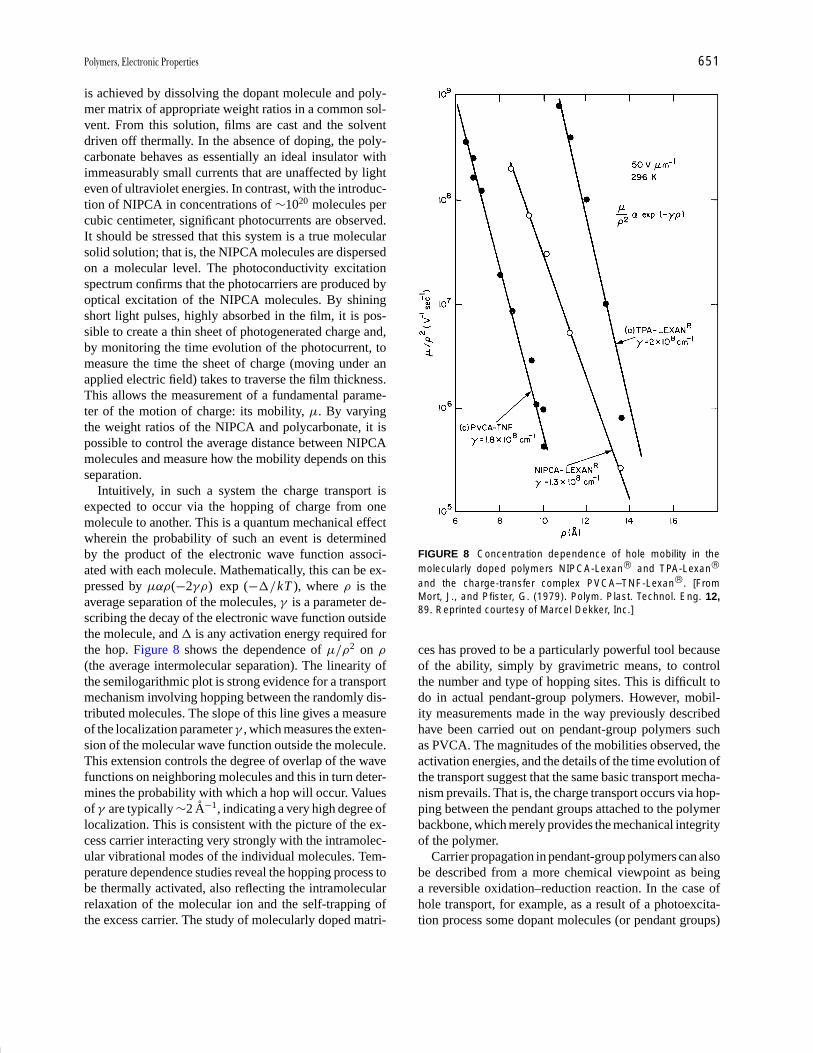
P1: GNH/MBS P2: GQT Final Pages
Encyclopedia of Physical Science and Technology En012j-597 July 26, 2001 11:8
Polymers, Electronic Properties 651
is achieved by dissolving the dopant molecule and poly-mer matrix of appropriate weight ratios in a common sol-vent. From this solution, films are cast and the solventdriven off thermally. In the absence of doping, the poly-carbonate behaves as essentially an ideal insulator withimmeasurably small currents that are unaffected by lighteven of ultraviolet energies. In contrast, with the introduc-tion of NIPCA in concentrations of ∼1020 molecules percubic centimeter, significant photocurrents are observed.It should be stressed that this system is a true molecularsolid solution; that is, the NIPCA molecules are dispersedon a molecular level. The photoconductivity excitationspectrum confirms that the photocarriers are produced byoptical excitation of the NIPCA molecules. By shiningshort light pulses, highly absorbed in the film, it is pos-sible to create a thin sheet of photogenerated charge and,by monitoring the time evolution of the photocurrent, tomeasure the time the sheet of charge (moving under anapplied electric field) takes to traverse the film thickness.This allows the measurement of a fundamental parame-ter of the motion of charge: its mobility, µ. By varyingthe weight ratios of the NIPCA and polycarbonate, it ispossible to control the average distance between NIPCAmolecules and measure how the mobility depends on thisseparation.
Intuitively, in such a system the charge transport isexpected to occur via the hopping of charge from onemolecule to another. This is a quantum mechanical effectwherein the probability of such an event is determinedby the product of the electronic wave function associ-ated with each molecule. Mathematically, this can be ex-pressed by µαρ(−2γρ) exp (−�/kT ), where ρ is theaverage separation of the molecules, γ is a parameter de-scribing the decay of the electronic wave function outsidethe molecule, and � is any activation energy required forthe hop. Figure 8 shows the dependence of µ/ρ2 on ρ(the average intermolecular separation). The linearity ofthe semilogarithmic plot is strong evidence for a transportmechanism involving hopping between the randomly dis-tributed molecules. The slope of this line gives a measureof the localization parameter γ , which measures the exten-sion of the molecular wave function outside the molecule.This extension controls the degree of overlap of the wavefunctions on neighboring molecules and this in turn deter-mines the probability with which a hop will occur. Valuesof γ are typically ∼2 A−1, indicating a very high degree oflocalization. This is consistent with the picture of the ex-cess carrier interacting very strongly with the intramolec-ular vibrational modes of the individual molecules. Tem-perature dependence studies reveal the hopping process tobe thermally activated, also reflecting the intramolecularrelaxation of the molecular ion and the self-trapping ofthe excess carrier. The study of molecularly doped matri-
FIGURE 8 Concentration dependence of hole mobility in themolecularly doped polymers NIPCA-Lexan and TPA-Lexan
and the charge-transfer complex PVCA–TNF-Lexan. [FromMort, J., and Pfister, G. (1979). Polym. Plast. Technol. Eng. 12,89. Reprinted courtesy of Marcel Dekker, Inc.]
ces has proved to be a particularly powerful tool becauseof the ability, simply by gravimetric means, to controlthe number and type of hopping sites. This is difficult todo in actual pendant-group polymers. However, mobil-ity measurements made in the way previously describedhave been carried out on pendant-group polymers suchas PVCA. The magnitudes of the mobilities observed, theactivation energies, and the details of the time evolution ofthe transport suggest that the same basic transport mecha-nism prevails. That is, the charge transport occurs via hop-ping between the pendant groups attached to the polymerbackbone, which merely provides the mechanical integrityof the polymer.
Carrier propagation in pendant-group polymers can alsobe described from a more chemical viewpoint as beinga reversible oxidation–reduction reaction. In the case ofhole transport, for example, as a result of a photoexcita-tion process some dopant molecules (or pendant groups)

P1: GNH/MBS P2: GQT Final Pages
Encyclopedia of Physical Science and Technology En012j-597 July 26, 2001 11:8
652 Polymers, Electronic Properties
FIGURE 9 Charge transport in doped polymer systems visual-ized as a donor–acceptor or an oxidation–reduction process.
become radical-cations (positively charged). As illustratedin Fig. 9, under the influence of an applied electric field,neutral molecules will repetitively transfer electrons toneighboring cations. The macroscopic manifestation ofthis microscopic process is hole transport. It must bestressed that this is purely electronic and not ionic mo-tion since no mass transport is involved. For hole transportto occur, therefore, one expects that the neutral moleculeshould be donorlike in its neutral state, whereas for elec-tron transport the neutral molecule should be acceptorlike.This has been confirmed experimentally since donorlikemolecules such as NIPCA, triphenylamine (TPA), andtri-p-tolylamine (TTA) exhibit only hole transport. Formolecules that are acceptorlike, that is, have a high elec-tron affinity, such as trinitrofluorenone (TNF), only elec-tron transport is observed.
Many of these concepts play a role in the process ofphotogeneration in which free carriers are created by pho-toexcitation. There are many potential consequences ofphotoexciting a molecule. The excitation can either relaxinternally within the molecule via nonradiative or radia-tive (fluorescence or phosphorescence) processes or it canthermalize (i.e., lose excess energy) into a bound electron–hole pair. This electron–hole pair can self-annihilate dueto the mutual attractive Coulomb force, or there is always aprobability, which can be enhanced by temperature or ap-plied electric field, for the pair to dissociate into a free elec-tron and hole. Many studies have demonstrated that thisprocess, or one very much like it, does occur in pendant-group polymers. A theory commonly invoked to explainthis phenomenon is due to Onsager and describes the prob-ability of dissociation of a thermalized electron–hole pair.Figure 10 shows the general predictions of theory; φ0 is thenumber of initially thermalized pairs, φ the number whichdissociate, and r0 the separation of the bound electron–hole pair after thermalization. A final critical parameter isthe Coulomb radius of the carrier pair, which is the dis-tance at which they just begin to feel their mutual attrac-tion. This is determined primarily by the dielectric con-stant κ of the material and for most polymers is ∼250 A.From Fig. 10, it can be seen that the number of dissociated
FIGURE 10 Excape probability predicted by Onsager theory forisotropic initial distribution of electron–hole pairs, T = 296 K, κ = 3.
electron–hole pairs (i.e., the number of free carriers) is es-sentially independent of the applied electric field but is astrong function of r0. This simply reflects the fact that, thecloser the electron–hole separation after thermalizationrelative to the Coulomb radius, the more difficult it be-comes for them to escape. For a given value of r0 the num-ber of dissociated pairs is a strong function of electric fieldand ultimately approaches unity; that is, all pairs dissoci-ate. Similar considerations apply to phenomena in poly-mers such as photosensitization in which a visibly absorb-ing molecule (i.e., a dye or pigment) is incorporated into apendant-group or molecularly doped polymer. In this case,the details become more complicated because of the in-teraction between dissimilar molecules. The photoexcitedmolecule is the sensitizer, and the photogeneration in-volves both this molecule and the pendant-group moleculeof the host polymer, whereas the ultimate transport ofthe freed charge may involve only the pendant-groupspecie.
As just discussed, transient increases in conductivitycan be achieved by exposure to light of appropriate wave-lengths. This photoconductivity decays to the quiescentequilibrium dark level, often with very large time constantsdue to trap emptying, on termination of the illumination.Typically in these insulating systems, this steady-statedark conductivity is extremely small. The excess conduc-tivity is produced by transient photooxidation of the pen-dant groups. This suggest that it should be possible toproduce controlled increases in the equilibrium dark ele-ctrical conductivity (σ ) by the use of variable equilibriumchemical oxidation or reduction of the pendant groups.
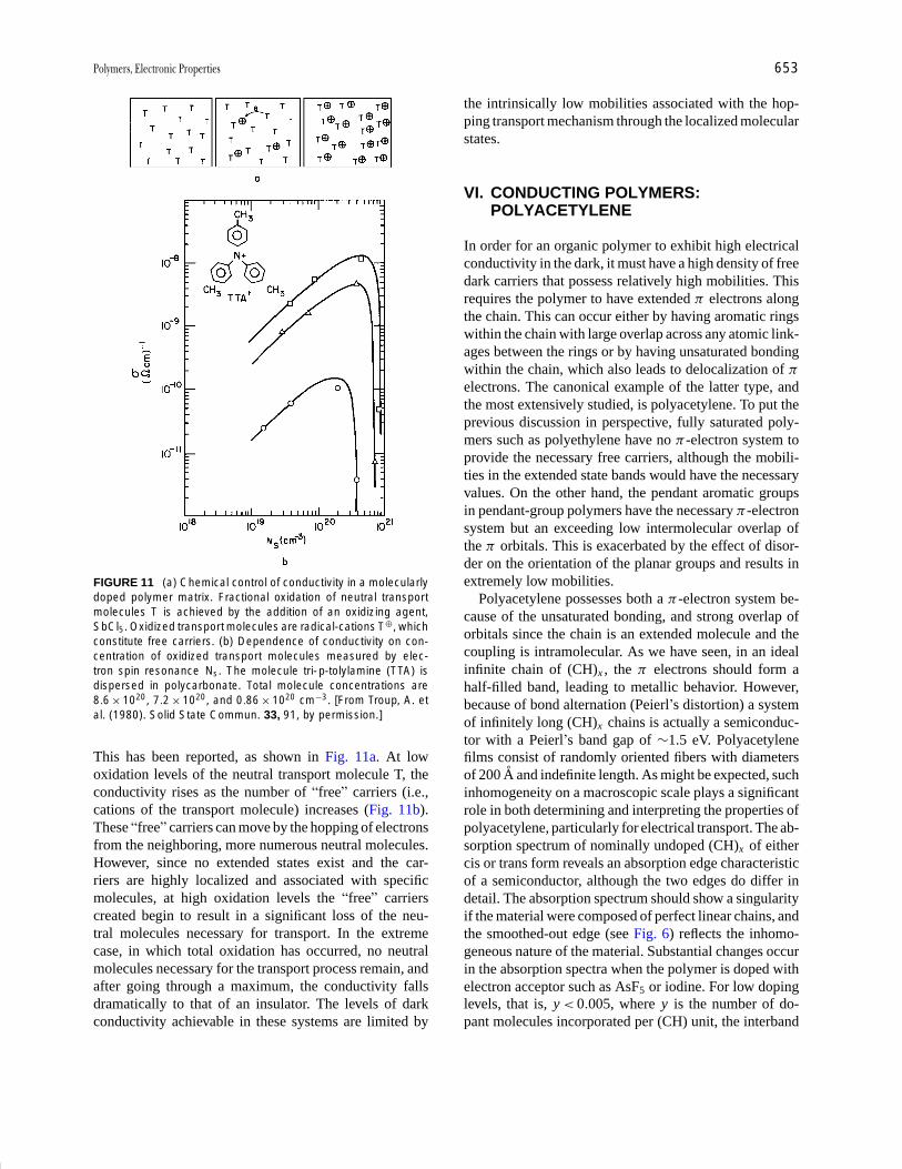
P1: GNH/MBS P2: GQT Final Pages
Encyclopedia of Physical Science and Technology En012j-597 July 26, 2001 11:8
Polymers, Electronic Properties 653
FIGURE 11 (a) Chemical control of conductivity in a molecularlydoped polymer matrix. Fractional oxidation of neutral transportmolecules T is achieved by the addition of an oxidizing agent,SbCl5. Oxidized transport molecules are radical-cations T⊕, whichconstitute free carriers. (b) Dependence of conductivity on con-centration of oxidized transport molecules measured by elec-tron spin resonance Ns. The molecule tri-p-tolylamine (TTA) isdispersed in polycarbonate. Total molecule concentrations are8.6 × 1020, 7.2 × 10²⁰, and 0.86 × 1020 cm−3. [From Troup, A. etal. (1980). Solid State Commun. 33, 91, by permission.]
This has been reported, as shown in Fig. 11a. At lowoxidation levels of the neutral transport molecule T, theconductivity rises as the number of “free” carriers (i.e.,cations of the transport molecule) increases (Fig. 11b).These “free” carriers can move by the hopping of electronsfrom the neighboring, more numerous neutral molecules.However, since no extended states exist and the car-riers are highly localized and associated with specificmolecules, at high oxidation levels the “free” carrierscreated begin to result in a significant loss of the neu-tral molecules necessary for transport. In the extremecase, in which total oxidation has occurred, no neutralmolecules necessary for the transport process remain, andafter going through a maximum, the conductivity fallsdramatically to that of an insulator. The levels of darkconductivity achievable in these systems are limited by
the intrinsically low mobilities associated with the hop-ping transport mechanism through the localized molecularstates.
VI. CONDUCTING POLYMERS:POLYACETYLENE
In order for an organic polymer to exhibit high electricalconductivity in the dark, it must have a high density of freedark carriers that possess relatively high mobilities. Thisrequires the polymer to have extended π electrons alongthe chain. This can occur either by having aromatic ringswithin the chain with large overlap across any atomic link-ages between the rings or by having unsaturated bondingwithin the chain, which also leads to delocalization of π
electrons. The canonical example of the latter type, andthe most extensively studied, is polyacetylene. To put theprevious discussion in perspective, fully saturated poly-mers such as polyethylene have no π -electron system toprovide the necessary free carriers, although the mobili-ties in the extended state bands would have the necessaryvalues. On the other hand, the pendant aromatic groupsin pendant-group polymers have the necessary π -electronsystem but an exceeding low intermolecular overlap ofthe π orbitals. This is exacerbated by the effect of disor-der on the orientation of the planar groups and results inextremely low mobilities.
Polyacetylene possesses both a π -electron system be-cause of the unsaturated bonding, and strong overlap oforbitals since the chain is an extended molecule and thecoupling is intramolecular. As we have seen, in an idealinfinite chain of (CH)x , the π electrons should form ahalf-filled band, leading to metallic behavior. However,because of bond alternation (Peierl’s distortion) a systemof infinitely long (CH)x chains is actually a semiconduc-tor with a Peierl’s band gap of ∼1.5 eV. Polyacetylenefilms consist of randomly oriented fibers with diametersof 200 A and indefinite length. As might be expected, suchinhomogeneity on a macroscopic scale plays a significantrole in both determining and interpreting the properties ofpolyacetylene, particularly for electrical transport. The ab-sorption spectrum of nominally undoped (CH)x of eithercis or trans form reveals an absorption edge characteristicof a semiconductor, although the two edges do differ indetail. The absorption spectrum should show a singularityif the material were composed of perfect linear chains, andthe smoothed-out edge (see Fig. 6) reflects the inhomo-geneous nature of the material. Substantial changes occurin the absorption spectra when the polymer is doped withelectron acceptor such as AsF5 or iodine. For low dopinglevels, that is, y < 0.005, where y is the number of do-pant molecules incorporated per (CH) unit, the interband
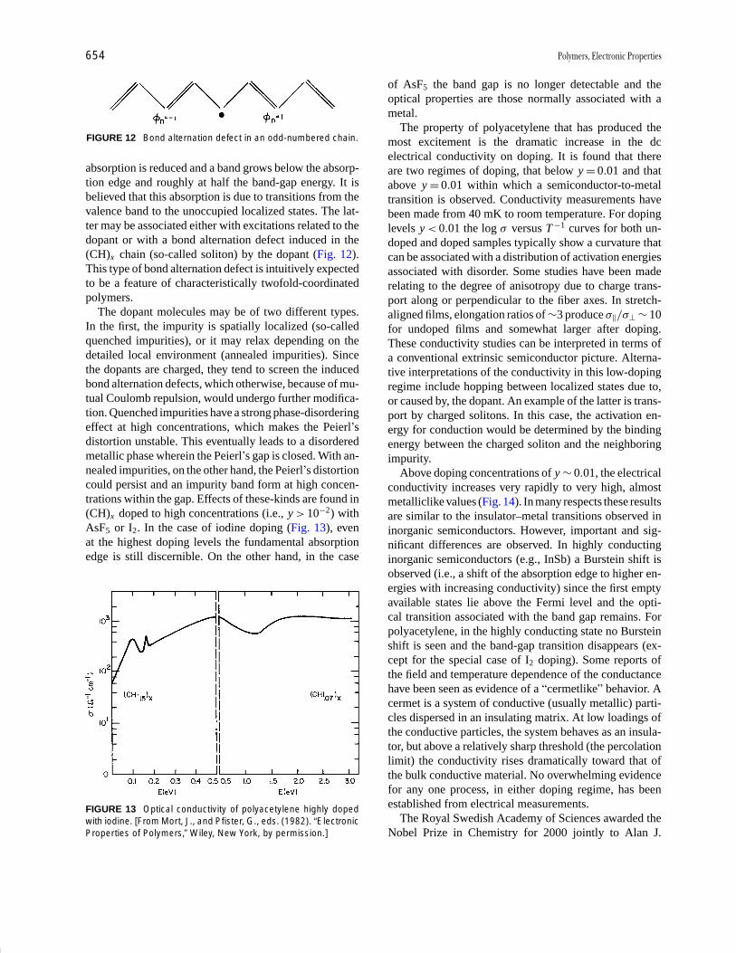
P1: GNH/MBS P2: GQT Final Pages
Encyclopedia of Physical Science and Technology En012j-597 July 26, 2001 11:8
654 Polymers, Electronic Properties
FIGURE 12 Bond alternation defect in an odd-numbered chain.
absorption is reduced and a band grows below the absorp-tion edge and roughly at half the band-gap energy. It isbelieved that this absorption is due to transitions from thevalence band to the unoccupied localized states. The lat-ter may be associated either with excitations related to thedopant or with a bond alternation defect induced in the(CH)x chain (so-called soliton) by the dopant (Fig. 12).This type of bond alternation defect is intuitively expectedto be a feature of characteristically twofold-coordinatedpolymers.
The dopant molecules may be of two different types.In the first, the impurity is spatially localized (so-calledquenched impurities), or it may relax depending on thedetailed local environment (annealed impurities). Sincethe dopants are charged, they tend to screen the inducedbond alternation defects, which otherwise, because of mu-tual Coulomb repulsion, would undergo further modifica-tion. Quenched impurities have a strong phase-disorderingeffect at high concentrations, which makes the Peierl’sdistortion unstable. This eventually leads to a disorderedmetallic phase wherein the Peierl’s gap is closed. With an-nealed impurities, on the other hand, the Peierl’s distortioncould persist and an impurity band form at high concen-trations within the gap. Effects of these-kinds are found in(CH)x doped to high concentrations (i.e., y > 10−2) withAsF5 or I2. In the case of iodine doping (Fig. 13), evenat the highest doping levels the fundamental absorptionedge is still discernible. On the other hand, in the case
FIGURE 13 Optical conductivity of polyacetylene highly dopedwith iodine. [From Mort, J., and Pfister, G., eds. (1982). “ElectronicProperties of Polymers,” Wiley, New York, by permission.]
of AsF5 the band gap is no longer detectable and theoptical properties are those normally associated with ametal.
The property of polyacetylene that has produced themost excitement is the dramatic increase in the dcelectrical conductivity on doping. It is found that thereare two regimes of doping, that below y = 0.01 and thatabove y = 0.01 within which a semiconductor-to-metaltransition is observed. Conductivity measurements havebeen made from 40 mK to room temperature. For dopinglevels y < 0.01 the log σ versus T −1 curves for both un-doped and doped samples typically show a curvature thatcan be associated with a distribution of activation energiesassociated with disorder. Some studies have been maderelating to the degree of anisotropy due to charge trans-port along or perpendicular to the fiber axes. In stretch-aligned films, elongation ratios of ∼3 produce σ‖/σ⊥ ∼ 10for undoped films and somewhat larger after doping.These conductivity studies can be interpreted in terms ofa conventional extrinsic semiconductor picture. Alterna-tive interpretations of the conductivity in this low-dopingregime include hopping between localized states due to,or caused by, the dopant. An example of the latter is trans-port by charged solitons. In this case, the activation en-ergy for conduction would be determined by the bindingenergy between the charged soliton and the neighboringimpurity.
Above doping concentrations of y ∼ 0.01, the electricalconductivity increases very rapidly to very high, almostmetalliclike values (Fig. 14). In many respects these resultsare similar to the insulator–metal transitions observed ininorganic semiconductors. However, important and sig-nificant differences are observed. In highly conductinginorganic semiconductors (e.g., InSb) a Burstein shift isobserved (i.e., a shift of the absorption edge to higher en-ergies with increasing conductivity) since the first emptyavailable states lie above the Fermi level and the opti-cal transition associated with the band gap remains. Forpolyacetylene, in the highly conducting state no Bursteinshift is seen and the band-gap transition disappears (ex-cept for the special case of I2 doping). Some reports ofthe field and temperature dependence of the conductancehave been seen as evidence of a “cermetlike” behavior. Acermet is a system of conductive (usually metallic) parti-cles dispersed in an insulating matrix. At low loadings ofthe conductive particles, the system behaves as an insula-tor, but above a relatively sharp threshold (the percolationlimit) the conductivity rises dramatically toward that ofthe bulk conductive material. No overwhelming evidencefor any one process, in either doping regime, has beenestablished from electrical measurements.
The Royal Swedish Academy of Sciences awarded theNobel Prize in Chemistry for 2000 jointly to Alan J.
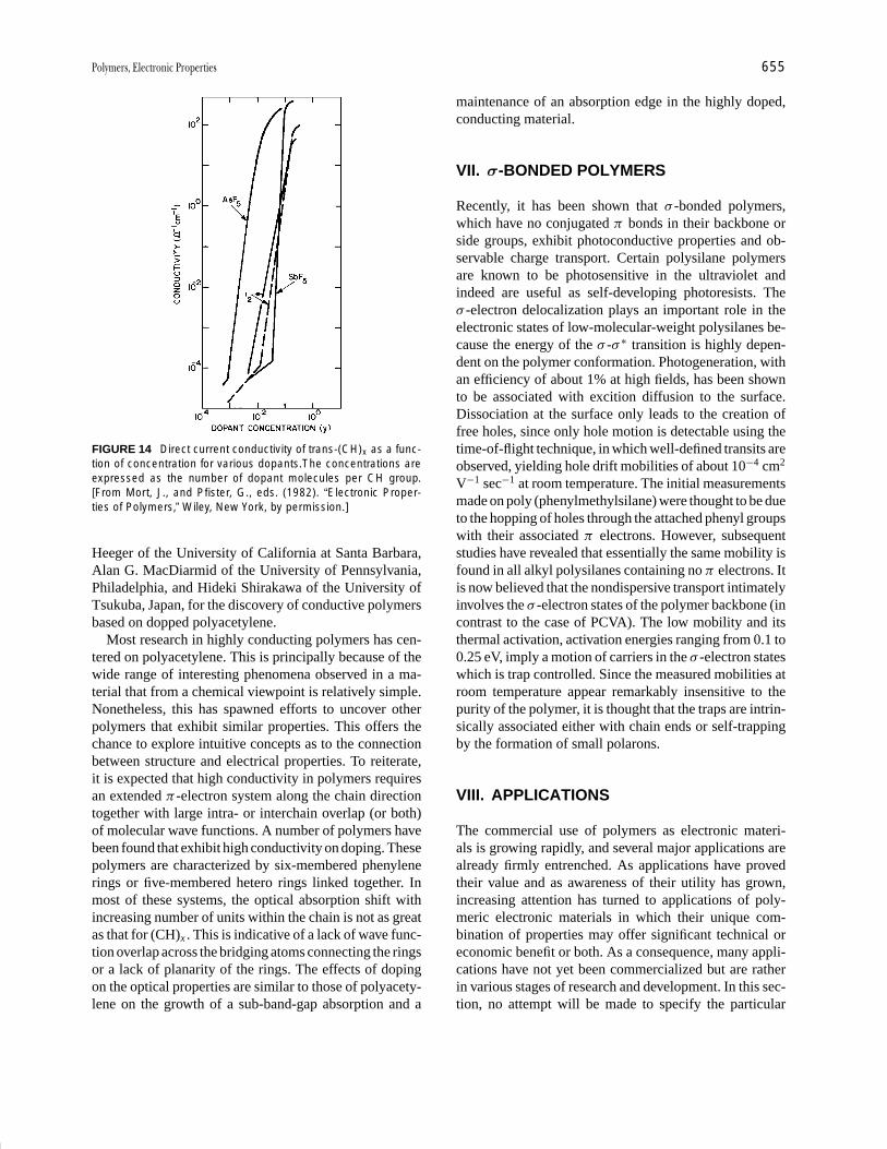
P1: GNH/MBS P2: GQT Final Pages
Encyclopedia of Physical Science and Technology En012j-597 July 26, 2001 11:8
Polymers, Electronic Properties 655
FIGURE 14 Direct current conductivity of trans-(CH)x as a func-tion of concentration for various dopants.The concentrations areexpressed as the number of dopant molecules per CH group.[From Mort, J., and Pfister, G., eds. (1982). “Electronic Proper-ties of Polymers,” Wiley, New York, by permission.]
Heeger of the University of California at Santa Barbara,Alan G. MacDiarmid of the University of Pennsylvania,Philadelphia, and Hideki Shirakawa of the University ofTsukuba, Japan, for the discovery of conductive polymersbased on dopped polyacetylene.
Most research in highly conducting polymers has cen-tered on polyacetylene. This is principally because of thewide range of interesting phenomena observed in a ma-terial that from a chemical viewpoint is relatively simple.Nonetheless, this has spawned efforts to uncover otherpolymers that exhibit similar properties. This offers thechance to explore intuitive concepts as to the connectionbetween structure and electrical properties. To reiterate,it is expected that high conductivity in polymers requiresan extended π -electron system along the chain directiontogether with large intra- or interchain overlap (or both)of molecular wave functions. A number of polymers havebeen found that exhibit high conductivity on doping. Thesepolymers are characterized by six-membered phenylenerings or five-membered hetero rings linked together. Inmost of these systems, the optical absorption shift withincreasing number of units within the chain is not as greatas that for (CH)x . This is indicative of a lack of wave func-tion overlap across the bridging atoms connecting the ringsor a lack of planarity of the rings. The effects of dopingon the optical properties are similar to those of polyacety-lene on the growth of a sub-band-gap absorption and a
maintenance of an absorption edge in the highly doped,conducting material.
VII. σ-BONDED POLYMERS
Recently, it has been shown that σ -bonded polymers,which have no conjugated π bonds in their backbone orside groups, exhibit photoconductive properties and ob-servable charge transport. Certain polysilane polymersare known to be photosensitive in the ultraviolet andindeed are useful as self-developing photoresists. Theσ -electron delocalization plays an important role in theelectronic states of low-molecular-weight polysilanes be-cause the energy of the σ -σ ∗ transition is highly depen-dent on the polymer conformation. Photogeneration, withan efficiency of about 1% at high fields, has been shownto be associated with excition diffusion to the surface.Dissociation at the surface only leads to the creation offree holes, since only hole motion is detectable using thetime-of-flight technique, in which well-defined transits areobserved, yielding hole drift mobilities of about 10−4 cm2
V−1 sec−1 at room temperature. The initial measurementsmade on poly (phenylmethylsilane) were thought to be dueto the hopping of holes through the attached phenyl groupswith their associated π electrons. However, subsequentstudies have revealed that essentially the same mobility isfound in all alkyl polysilanes containing no π electrons. Itis now believed that the nondispersive transport intimatelyinvolves the σ -electron states of the polymer backbone (incontrast to the case of PCVA). The low mobility and itsthermal activation, activation energies ranging from 0.1 to0.25 eV, imply a motion of carriers in the σ -electron stateswhich is trap controlled. Since the measured mobilities atroom temperature appear remarkably insensitive to thepurity of the polymer, it is thought that the traps are intrin-sically associated either with chain ends or self-trappingby the formation of small polarons.
VIII. APPLICATIONS
The commercial use of polymers as electronic materi-als is growing rapidly, and several major applications arealready firmly entrenched. As applications have provedtheir value and as awareness of their utility has grown,increasing attention has turned to applications of poly-meric electronic materials in which their unique com-bination of properties may offer significant technical oreconomic benefit or both. As a consequence, many appli-cations have not yet been commercialized but are ratherin various stages of research and development. In this sec-tion, no attempt will be made to specify the particular
P1: GNH/MBS P2: GQT Final Pages
Encyclopedia of Physical Science and Technology En012j-597 July 26, 2001 11:8
656 Polymers, Electronic Properties
stage that potential applications have reached except toindicate those that have already entered the marketplaceand proved their worth.
Conductive plastics are presently used in, or being de-veloped industrially for antistatic substances for photo-graphic film, shields for computer screen against elec-tromagnetic radiation, and for “smart” windows (that canexclude sunlight on demand). In addition, semiconductivepolymers have recently been developed for use in light-emitting diodes and solar cells and as displays in mobiletelephones and miniformat television screens.
A major commercial application of polymer electrets isas electroacoustic transducers such as microphones. Theircommercial acceptance is based on several advantagesover condenser microphones. Among these are an insen-sitivity to mechanical shock and electromagnetic pickup.They are much simpler in design and less expensive. Ina typical microphone, a thin polymer electret is attachedto a back electrode and a front diaphragm. Incident soundinduces vibration of the diaphragm, and the vibration ofthe electret thus generates an ac signal. This type of mi-crophone and variations are used in cassette recorders,hearing aids, stereo equipment, and sound level detectionand telecommunications. Current worldwide production is∼100 million units on an annual basis. The piezoelectricproperties of PVF2 have also led to its use in commercialelectroacoustic applications. In all cases, the chief advan-tages of polymers are their flexibility, toughness, and ca-pacity to be easily processed in large-area, thin films ofpractically any shape. They also possess low mechanicalimpedance and therefore have the virtue of good acousticcoupling to water and the human body. These two qual-ities, together with the others, have suggested potentialimportant applications ranging from medical, biological,and geological to military. The good impedance match tothe human body suggests use as real-time, in vitro heartrate monitoring (e.g., fetal phonocardiographs). In marinetechnology, the monitoring of underwater acoustic signalswhether from marine life or human-made objects such assubmarines becomes possible. The piezoelectric proper-ties of PVF2 allows its use as transducers in inkjet print-ers, printing pressure monitors, blood pressure monitors,strain gauges, accelerometers, and the like. The pyroelec-tric properties have led to the use of PVF2 as an infrareddetector with a fast response time because of the smallheat capacity achievable with thin films. These detectorscan also be produced in very large areas and thereforehave potential security applications such as burglar andfire alarms.
The triboelectric properties of polymers have enormousapplications in the area of electrophotography and dry-inkelectrophotography. The basic feature of electrophotogra-phy is the production of a latent electrostatic pattern that
replicates the information to be produced either from anoriginal or from electronic input. This electrostatic pat-tern can be produced by selective photodischarging of auniformly charged photoreceptor surface or by selectivecharging of a surface with an ion beam. The latent elec-trostatic pattern must then be developed. In dry copying,as opposed to liquid ink development, the image is ren-dered visible by moving a developer material across thesurface of the photoreceptor. This developer material is afine powder that consists of black or colored toner parti-cles, which are polymer spheres (∼10 µm in diameter)in which a colorant such as carbon black is encapsulated.These toner particles are charged by a triboelectric processto a sign opposite to that with which the photoreceptor wasoriginally charged. (By proper choice of materials eitherpolarity of triboelectric charge can be obtained.) The op-positely charged toner particles are therefore attracted bythe latent electrostatic pattern and render it visible. Thistoner pattern is then transferred to paper from the photore-ceptor and fixed. This is usually done thermally, by whichprocess the polymer spheres melt and adhere to the paper.Considering that billions of copies are made per year, thecommercial significance of tribelectricity in polymers canbe appreciated.
Another significant application of polymers as elec-tronic materials in electrophotography is as photorecep-tors. Polymers that are electrically insulating in the darkbut can transport nonequilibrium carriers produced bylight are well suited to function as photoreceptor ele-ments. Polymers such as PVCA or molecularly dopedpolymers have strong intrinsic optical absorption only inthe ultraviolet, and since visible light is employed in prac-tice, the polymer photosensitivity must be extended intothe visible. This can be done by (1) the formation of acharge-transfer complex with absorption in the visible,(b) dye sensitization with an appropriately absorbing dye,or (c) the use of a thin, contiguous sensitizing layer such asamorphous selenium or an organic pigment. The abilityto make large-area flexible polymer films at relativelylow cost by solution coating accounts for the applica-tion of these materials in electrophotography. Although inpendant-group polymers or polymers doped with aromaticmolecules charge transport is a hopping process with in-herently low mobilities, less than 10−3 cm2 V−1 sec−1, thisis not a limitation for electrophotographic usage. In thisprocess, the most important parameter, within limits, ishow far the carriers move before they are immobilizedrather than how fast they travel. For most process speeds,such mobilities are adequate provided that the photogen-erated carriers can traverse the total device thickness, thatis, µEτ> sample thickness, where µ is the mobility, E theelectric field, and τ the lifetime of carriers with respect todeep traps. Remarkably, such polymers do exhibit large
P1: GNH/MBS P2: GQT Final Pages
Encyclopedia of Physical Science and Technology En012j-597 July 26, 2001 11:8
Polymers, Electronic Properties 657
carrier ranges because of their very long deep-trappinglifetimes.
For systems in which the photogeneration occurs byphotoexcitation within a polymer, such as the charge-transfer complexes or dye-sensitized systems, the pho-togeneration efficiency can be controlled by a geminaterecombination mechanism. This type of carrier recombi-nation in molecular systems can lead to quantum efficien-cies for photogeneration that are substantially less thanunity and are strongly field dependent. This may result ina photosensitivity limitation, depending on the particularsystem, and can be overcome to some degree by increasingthe light exposure in a machine.
For other electronic applications, the magnitudes of thecarrier mobilities are of paramount importance, since theydetermine the frequency response of devices or, throughthe related diffusion lengths, determine ultimate collectionefficiencies in devices such as photovoltaic cells. Pendant-group polymers and disordered molecularly doped sys-tems are not likely to find applications in these areas be-cause of their low mobilities and the probable importanceof geminate recombination processes.
A major commercial application of highly conductivepolymers, such as doped polyacetylene, has yet to be re-alized. Potential uses that have been explored or are cur-rently under study include experimental photovoltaic andphotoelectrochemical cells and lightweight rechargeablebatteries. Organic batteries, based on reversible electro-chemical doping, in particular, appear to hold the most
technological promise, although, because of the infancyof this class of electronic polymers, further advances lead-ing to other innovations cannot be ruled out.
SEE ALSO THE FOLLOWING ARTICLES
ELECTRONS IN SOLIDS • FULLERENES AND CARBON
NANOTUBES • ORGANIC CHEMICAL SYSTEMS, THEORY
• PHOTOGRAPHIC PROCESSES AND MATERIALS • POLY-MERS, FERROELECTRIC • POLYMERS, SYNTHESIS
BIBLIOGRAPHY
Chiang, C. K., Druy, M. A., Gau, S. C., Heeger, A. J., Louis, E. J.,MacDiarmid, A. J., Park, Y. W., and Shirakawa, H. (1978). “Synthesisof highly conducting films of derivatives of poyacetylene (CH)x ,”J. Am. Chem. Soc. 100, 1013.
Farges, J.-P. (1994). “Organic Conductors: Fundamentals and Applica-tions,” Marcel Dekker, New York.
Kahol, P. K., Harbeke, G., and Clark, G. C. (1992). “Conjugated Con-ducting Polymers,” Springer-Verlag, Berlin/New York.
Kroschwitz, J., ed. (1988). “Electrical and Electronic Properties of Poly-mers: A State-of-the-Art Compendium,” Wiley, New York.
Nalwa, H. S. (1997). “Handbook of Organic Conductive Molecules andPolymers: Vol. 1, Charge-Transfer Salts, Fullerenes and Photocon-ductors,” Vol. 1, Wiley, New York.
Okamura, S., and Ranby, B. (1994). “Photoconducting Polymers/Metal-Containing Polymers,” Springer-Verlag, Berlin/New York.
Skotheim, T. A., and Elsenbaumer, R. L. (1997). “Handbook of Con-ducting Polymers,” 2nd ed., Marcel Dekker, New York.
P1: GPB/GLT P2: GQT Final Pages Qu: 00, 00, 00, 00
Encyclopedia of Physical Science and Technology en012f-594 July 26, 2001 11:9
Polymers, FerroelectricT. C. Mike ChungA. PetchsukPennsylvania State University
I. Definition of Piezo-, Pyro-,and Ferroelectrics
II. Conventional Piezoelectric Polymers:Poly (vinylidene fluoride) and Its Copolymers
III. New Piezoelectric VDF/TrFE/CTFETerpolymers
IV. Other Ferroelectric PolymersV. Applications
GLOSSARY
Actuator Transducer capable of transducing an inputenergy into mechanical output energy (displacement/force).
Dielectric constant The relative permittivity (comparedwith vacuum) that represents the charge-storing capac-ity of a dielectric material in the presence of an externalelectric field.
Electroactive polymer Polymer whose shape can bechanged under an electric field to perform energy con-version between the electric form and the mechanicalform.
Electrostriction Phenomenon in all dielectric materialswhich gives rise to a strain that is proportional to thesquare of the applied electric field.
Ferroelectric polymer Polymer whose direction of spon-taneous polarization can be reversed under an electricfield.
Poly(vinylidene fluoride) Polymer consisting of vinyli-dene fluoride monomer units.
Sensor A detection device that produces a measurableresponse to a change in a physical condition, such astemperature or pressure.
VDF/TrFE/CTFE terpolymer A random copolymerconsisting of three different monomers: vinylidene flu-oride, trifluoroethylene, and chlorotrifluoroethylene.
STRONG INTEREST has been generated in recentdecades regarding the development of ferroelectric, piezo-electric, and magnetostrictive materials with high perfor-mance for such applications as electromechanical trans-ducers, actuators, and sensors. However, many traditionalelectroactive materials (piezoceramic and magnetostric-tive materials) have been found to suffer from low strainresponse (<1%), despite their high dielectric constant, lowhysteresis, and fast speed. Developing new ferroelectric,piezoelectric, and magnetostrictive materials with highstrain, high elastic density, and high electromechanicalcoupling has been a scientific and technological challenge.Recently, polymeric materials have received much more
659
P1: GPB/GLT P2: GQT Final Pages
Encyclopedia of Physical Science and Technology en012f-594 July 26, 2001 11:9
660 Polymers, Ferroelectric
extensive attention as new ferroelectric or piezoelectricmaterials. Compared to current ceramic-based materials,polymeric materials could offer many unique features,such as light weight, low cost, great mechanical strength,easy processability into thin and flexible films of variousshapes and sizes, high reliability, large strain, and, mostimportantly, flexible architecture design via moleculartailoring.
It was not until 1969 that Kawai demonstrated thesignificant increase of piezoelectricity in poly(vinylidenefluoride); pyroelectricity and ferroelectricity were re-ported in 1971. Since then, tremendous growth in thenew field of ferroelectric polymers has occurred. Theexploration of the chemistry, physics, and technology ofpoly(vinylidene fluoride) led to the search for other classesof novel ferroelectric polymers, such as its copolymers,odd-numbered polyamides, cyanopolymers, polyureas,polythioureas, biopolymers (including polypeptides), andferroelectric liquid crystal polymers. Significant progresshas been made both in finding new materials and in betterunderstanding structure–property relationships.
In this review, the primary goals are to update currentresearch in ferroelectric polymers and provide a funda-mental understanding of ferroelectric physics. Since manyextensive reviews of poly(vinylidene fluoride) and itscopolymers already exist in great detail, only a briefsummary is given of their chemical synthesis, structure-electrical property relationships, and applications. Someemphasis will be on the newly developed VDF/TrFE/CTFE terpolymers containing vinylidene difluoride(VDF), trifluoroethylene (TrFE), and chlorotrifluo-roethylene (CTFE) units. These processable terpolymersshow high dielectric constants, narrow polarizationhysteresis loops, and large electrostrictive responses atambient temperature. The last section will cover someother novel ferroelectric polymers, such as polyamides,polyurethanes, and polyureas. No attempt is made todiscuss ferroelectric biopolymers and ferroelectric liquidcrystal polymers, comprehensive reviews of which areavailable elsewhere.
I. DEFINITION OF PIEZO-, PYRO-,AND FERROELECTRICS
It is well established that electrical properties such aspiezoelectricity and pyroelectricity can only exist in ma-terials lacking a center of symmetry. In fact, among the 32classes of the crystal point symmetry group, only 20 canexhibit piezoelectric and pyroelectric effects. A piezoelec-tric material is one that develops electric polarization onlywhen mechanical stress is applied. Pyroelectric materialspossess a permanent polarity (spontaneous polarization)
which responds not only to stress, but also to temperaturechange. Pyroelectric crystals whose spontaneous polariza-tion can be reversed by an external electric field are calledferroelectrics.
A. Piezoelectric d Constant
The magnitude of the induced strain x by an external fieldE or the dielectric displacement D by a stress X is repre-sented in terms of the piezoelectric d constant (an impor-tant parameter for acoustic applications)
x = d E (1a)
D = d X. (1b)
The effect in Eq. (1b) is the direct piezoelectric effect,where the induced charge is proportional to the mechan-ical stress, whereas the effect in Eq. (1a) is the conversepiezoelectric effect. Extending Eqs. (1a) and (1b) withthe use of the linear elastic (Hooke’s law) and dielectricequations, and writing the results in matrix notation formyields
xi = s Ei j X j + dmi Em, (2a)
Dm = dmi Xi + εXmk Ek, (2b)
where s Ei j is the elastic compliance, εX
ik is the dielectric per-mittivity, i, j = 1, 2, . . . , 6, and m, k, = 1, 2, 3. The su-perscripts refer to the conditions under which these quan-tities are measured, that is, compliance is measured underconstant electric field, and permittivity is measured underconstant stress. ε0 is the vacuum dielectric permittivity(=8.85 × 10⁻¹² F/m).
B. Piezoelectric g Constant
The induced electric field E is related to an external stressX through the piezoelectric voltage constant g, which isan important parameter for sensor applications:
E = gX. (3)
Taking into account D = d X , we obtain
g = d
εε0. (4)
C. Field-Related and Charge-RelatedElectrostrictive Coefficients
Generally, there are two phenomenologies used to de-scribe the electric field-induced strain: the electrostric-tive and piezoelectric effects. The piezoelectric effect isa primary electromechanical coupling effect in which the
P1: GPB/GLT P2: GQT Final Pages
Encyclopedia of Physical Science and Technology en012f-594 July 26, 2001 11:9
Polymers, Ferroelectric 661
strain is proportional to the electric field, whereas the elec-trostrictive effect is a secondary effect in which the strainis proportional to the square of the electric field (this effectexists in any polymer). Electrostriction can be expressedas
x = M E2, (5)
x = Q P2. (6)
where P = εε0 E in the paraelectric phase and P = Ps
+ εε0 E in the ferroelectric phase. The electric field-related electrostrictive coefficient M and charge-relatedelectrostrictive coefficient Q are related to each otherthrough M = Qε2
0ε2 .
For an isotropic polymer,
x33 = Q33 P2, x31 = Q31 P2, (7)
where the two numerals in the subscripts refer to the elec-tric field direction and the measured polarization direction,respectively. Therefore, x33 and x31 are strains parallelto and perpendicular to the polarization direction, knownas longitudinal and transverse strains, respectively. Forisotropic polymers, both experimental and theoretical datashow that Q11 < 0, Q13 > 0, M33 < 0, and M13 > 0, hencethe polymer will contract along the polarization directionas the polarization increases. In other words, the polymerwill contract along the thickness direction and will expandalong the film direction when an electric field is appliedacross the thickness.
It should be noted that most polymers exhibit nonlineardielectric behavior and deviate from Eq. (5) in a high field,where the field-induced strain will be saturated.
D. Electromechanical Coupling Factor K
The electromechanical coupling factor K is related to theconversion rate between electrical energy and mechanicalenergy; K 2 is the ratio of stored mechanical energy to inputelectrical energy, or the ratio of stored electrical energy toinput mechanical energy.
When an electric field E is applied to a piezoelectricmaterial, K 2 can be calculated as
K 2 = d2/εε0s. (9)
There are many electromechanical coupling factors corre-sponding to the direction of the applied electric field andto the mechanical strain (or stress) direction. For instance,in cases where a polymer actuator is made with the elec-tric field along the 3-direction, the mechanical couplingfactor is longitudinal to the electromechanical couplingfactor K33, which can be related to the Eq. (9) as
K 233 = d2
33
/εX
33ε0s E33. (10)
E. Acoustic Impedance Z
The acoustic impedance Z is a parameter used for evalu-ating the acoustic energy transfer between two materials.It is defined as Z2 = pressure/volume · velocity. In solidmaterial,
Z = √ρ · c (11)
where ρ is the density and c is the elastic stiffness of thematerial.
Piezoelectric ferroelectrics fall into four classes: opti-cal active polymers, poled polar polymers, ferroelectricpolymers, and ceramic/polymer composites. The polingprocedure involves the application of an external fieldto a ferroelectric to induce a cooperative alignment ofconstituent dipoles. Most polymers in the first group arebiological materials, such as derivatives of cellulose,proteins, and synthetic polypeptides. The origin of piezo-electricity in these polymers is attributed to the internalrotation of the dipoles of asymmetric carbon atoms, whichgives rise to optical activity. The second class of piezo-electric polymers includes polyvinyl chloride (PVC),polyvinyl fluoride (PVF), polyacrylonitriles (PAN), odd-numbered nylons, and copolymers of vinylidene cyanide.The piezoelectricity in these polymers is caused by thetrifluoroethylene (TrFE) or tetrafluoroethylene (TFE).Recently, other polymers were found to show ferroelectricbehavior, such as copolymers of vinylidene cyanide,odd-numbered nylons, and polyureas, in which piezo-electricity arises from the functional polar groups in thepolymer molecules. In the fourth class (polymer/ceramiccomposites), the piezoelectric activity comes from theintrinsic piezoelectricity of ceramics. Physical propertiesof these composites can be controlled by the choice ofthe ferroelectric ceramics and the polymer matrix. Theyhave a combination of high piezoelectric activity from theferroelectric ceramics and flexibility from the polymermatrix.
Table I compares the piezoelectric properties of theferroelectric ceramics and polymers. The piezoelectricstrain constant d31 of polymers is relatively low com-pared to that of ceramics. However, the piezoelectric volt-age constant g31 is larger. In addition, polymers have ahigh electromechanical coupling factor and low acousticimpedance, which permit their use in ultrasonic transducerapplications and medical instrumentation. The combina-tion of these properties with their flexibility, light weight,toughness, and availability in large-area sheets has ledto tremendous growth in research on novel ferroelectricpolymers.

P1: GPB/GLT P2: GQT Final Pages
Encyclopedia of Physical Science and Technology en012f-594 July 26, 2001 11:9
662 Polymers, Ferroelectric
TABLE I Typical Physical, Piezoelectric, and Pyroelectric Properties of Various Materials
Piezoelectric constantsDensity Modulus Pyroelectric Dielectric Coupling Acoustic
ρ C11 d31 e31 g31 constant constant factor impedanceMaterial a (g/cm3) (GN/m2) (pC/N) (pC/N) (mV-m/N) (µC/K-m2) (εr) k31 (Gg/m2-sec)
PVDF 1.78 1–3 20 6.0 174 30–40 10–15 0.1 2–3
P(VDF/TrFE) ∼1.9 1.2 15–30 2–3 100–160 30–40 15–30 0.2
PVF 1.4 1 1 10
PVC 1.5 4 1 1–3 3
Nylon-11 1.1 1.5 3 6.2 3 4 0.1–0.15
Nylon-11/PVDF 2.3 41 109 13.8
Laminate film
P(VDCN/VAc) 1.2 4.5 6 2.7 169 4.5 0.06
PTUFB 3.0 20–30
PVDF/PZT 5.3 3.0 20 6.0 19 120 0.07
Rubber/PZT 5.6 0.04 35 1.4 72 55 0.01
POM/PZT 4.5 2.0 17 3.4 20 95 0.08
Quartz 2.65 77.2 2 15.4 50 4.5 0.09
PZT 7.5 83.3 110 920 10 1200 0.31
a PVDF, poly(vinylidene fluoride); P(VDF/TrFE), poly(vinylidene fluoride-co-trifluoroethylene); PVF, polyvinyl fluoride; PVC, polyvinyl chloride;P(VDCN/Vac), poly(vinylidene cyanide-co-vinyl acetate); PTUFB, polyurea–formaldehyde; PZT, lead zirconate titanate.
II. CONVENTIONAL PIEZOELECTRICPOLYMERS: POLY(VINYLIDENEFLUORIDE) AND ITS COPOLYMERS
A. Poly(vinylidene fluoride)
1. Synthesis
Poly(vinylidene fluoride) (PVDF) is commercially prod-uced by free radical polymerization of 1,1-difluoro-ethylene (CH2 CF2) at high temperature (50–150◦C)and high pressure (10–300 atm). The most commonpolymerization process is emulsion or suspension usingwater as a reaction medium. The catalysts used in theseprocesses are either inorganic (persulfate) or organicperoxides. Since the monomer units of PVDF have adirectionality (CH2 is denoted the “head” and CF2 the“tail”), typically 5% of the monomer units enter thegrowing chain with a reverse orientation, leading tohead-to-head and tail-to-tail defects. These defects causea reduction of the average dipoles by 6–10%. Polymerswith defect concentrations ranging from 0.2% to 23.5%have been synthesized and the effect of defects on crystalstructure has been studied.
2. Molecular and Crystal Structure
PVDF ( CH2 CF2 ) has a chemical structure in betweenthose of PE ( CH2CH2 ) and PTFE ( CF2CF2 ). Un-like PTFE, which has a helical conformation due to thesteric hindrance of the fluorine atom, or PE, which takes
the most stable conformation (all-trans conformation dueto low rotational barrier), PVDF can take several confor-mations. The three known conformations are tg+tg−, all-trans, and t t tg+t t tg−. The first two conformations are themost common and important ones, and are schematicallydrawn in Fig. 1.
The C F bond is a polar bond (dipole moment µ =6.4 × 10⁻³⁰ C-m), and contributes to the polar conforma-tion. The all-trans conformation has the highest dipolemoment (µ = 7.0 × 10− 30 C-m/repeat) due to the align-ment of all dipoles in the same direction. The tg+tg−
conformation is also polar, but the net dipoles that are per-pendicular and parallel to the chain are approximately thesame, giving rise to lower net dipole.
The packing of these polar chains in a crystal adoptsseveral distinct morphologies in PVDF. At least four areknown, the α, β, γ , and δ phases, which can easily betransformed into one another. The most common one isthe α phase, which may be obtained by crystallizationfrom the melt. As depicted in Fig. 1, the unit cell of the αphase consists of two tg+tg− chain conformations whosedipole components normal to the chain are antiparallel andneutral to each other. Thus the α phase is a nonpolar phase.The polar analog δ phase can be obtained by poling undera high electric field. The lattice dimensions of these twophases are essentially the same: a = 4.96 A, b = 9.64 A,and c = 4.96 A.
The β phase is the most highly polar and importantphase, and is typically prepared by stretching polymer filmat room temperature or by crystallization from the melt
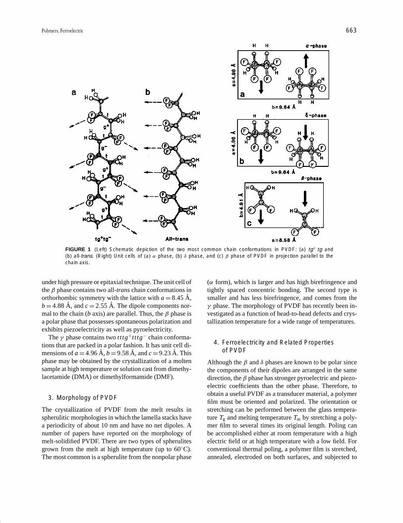
P1: GPB/GLT P2: GQT Final Pages
Encyclopedia of Physical Science and Technology en012f-594 July 26, 2001 11:9
Polymers, Ferroelectric 663
FIGURE 1 (Left) Schematic depiction of the two most common chain conformations in PVDF: (a) tg+ tg and(b) all-trans. (Right) Unit cells of (a) α phase, (b) δ phase, and (c) β phase of PVDF in projection parallel to thechain axis.
under high pressure or epitaxial technique. The unit cell ofthe β phase contains two all-trans chain conformations inorthorhombic symmetry with the lattice with a = 8.45 A,b = 4.88 A, and c = 2.55 A. The dipole components nor-mal to the chain (b axis) are parallel. Thus, the β phase isa polar phase that possesses spontaneous polarization andexhibits piezoelectricity as well as pyroelectricity.
The γ phase contains two t t tg+t t tg− chain conforma-tions that are packed in a polar fashion. It has unit cell di-mensions of a = 4.96 A, b = 9.58 A, and c = 9.23 A. Thisphase may be obtained by the crystallization of a moltensample at high temperature or solution cast from dimethy-lacetamide (DMA) or dimethylformamide (DMF).
3. Morphology of PVDF
The crystallization of PVDF from the melt results inspherulitic morphologies in which the lamella stacks havea periodicity of about 10 nm and have no net dipoles. Anumber of papers have reported on the morphology ofmelt-solidified PVDF. There are two types of spherulitesgrown from the melt at high temperature (up to 60◦C).The most common is a spherulite from the nonpolar phase
(α form), which is larger and has high birefringence andtightly spaced concentric bonding. The second type issmaller and has less birefringence, and comes from theγ phase. The morphology of PVDF has recently been in-vestigated as a function of head-to-head defects and crys-tallization temperature for a wide range of temperatures.
4. Ferroelectricity and Related Propertiesof PVDF
Although the β and δ phases are known to be polar sincethe components of their dipoles are arranged in the samedirection, the β phase has stronger pyroelectric and piezo-electric coefficients than the other phase. Therefore, toobtain a useful PVDF as a transducer material, a polymerfilm must be oriented and polarized. The orientation orstretching can be performed between the glass tempera-ture Tg and melting temperature Tm by stretching a poly-mer film to several times its original length. Poling canbe accomplished either at room temperature with a highelectric field or at high temperature with a low field. Forconventional thermal poling, a polymer film is stretched,annealed, electroded on both surfaces, and subjected to

P1: GPB/GLT P2: GQT Final Pages
Encyclopedia of Physical Science and Technology en012f-594 July 26, 2001 11:9
664 Polymers, Ferroelectric
an electric field of about 0.5 MV/cm at high temperature(80–100◦C), followed by cooling in the presence of theapplied field. Other methods of poling include corona dis-charge, plasma, and poling during orientation.
For many years, there was debate over the origins ofthe piezoelectric and pyroelectric properties in PVDF.The arguments seem to have reached the conclusion thatthe properties primarily arise from the dipole orientation,rather than from trapped space charge. The discovery ofthe enhancement of piezoelectric activity in PVDF byKawai led to the revelation of others properties, such as py-roelectricity and ferroelectricity. Although there is no ob-vious evidence of a Curie transition in PVDF, the existenceof polarization loops together with polarization reversaland the switching phenomenon is generally accepted asproof of ferroelectricity in PVDF. Figure 2 shows the D–Ehysteresis loops at various temperatures. Even at −100◦Ca square-shape hysteresis loop is clearly observed with aremanent polarization Pr about 60 mC/m2, which does notchange with temperature. However, the coercive field Ec,which is the electric field used for neutralizing polariza-tion in the material, is temperature-dependent. The value isabout 50 MV/m at room temperature and remains almostconstant above the glass transition temperature (−50◦C),but increases sharply at lower temperatures.
The remanent polarization Pr, which is the polariza-tion after the field has been removed, is dependent on thecrystallinity. For PVDF, the calculated macroscopic polar-ization for 100% alignment of all dipoles is 130 mC/m2,and the measured polarization of 60 mC/m2 is consistent
FIGURE 2 The D–E hysteresis loops of PVDF at various electricfields.
with about 50% crystallinity and perfect alignment. Thedirection of Pr can be reversed by subsequent applicationof the field in the opposite direction. This phenomenon,called ferroelectric switching, has been investigated exten-sively to elucidate the mechanism of polarization reversal.
Although PVDF exhibits strong piezoelectric and pyro-electric properties, it is necessary that the polymer film besubjected to mechanical stretching and electrical polingto get the β phase. Such procedures include, for exam-ple, subjecting the ferroelectric polymer to mechanicaldeformation, electron irradiation, uniaxial drawing, crys-tallization under high pressure, and crystallization underhigh electric field. It is tempting to speculate about howmuch improvement of the dielectric, piezoelectric, and py-roelectric properties may yet be achieved by modificationof the chemical structure of the polymer. Some improve-ment has been achieved by synthesizing copolymers ofvinylidene fluoride with trifluoroethylene (TrFE), tetraflu-oroethylene (TFE), or vinyl fluoride (VF), and, indeed,some of these copolymers exhibit even higher piezoelec-tric and pyroelectric properties that will be discussed inthe next section.
B. Poly(vinylidene fluoride–trifluoroethylene)(VDF/TrFE) Copolymer
P(VDF/TrFE) is the most studied copolymer. Lando et al.and Yagi et al. initially studied the properties and struc-ture of this copolymer. The randomly distributed VDF andTrFE units form the cocrystalline phase in the whole com-position range of the copolymers. The greater proportionof bulky trifluorine atoms in PVDF prevents the molec-ular chains from accommodating the tg+tg− conforma-tion. Therefore, copolymers crystallize at room temper-ature into a ferroelectric phase with the extended planarzigzag (all-trans) conformation, whose crystalline phaseis similar to the β phase of PVDF homopolymer.
1. Ferroelectric–Paraelectric Phase Transition
Probably the solid evidence for the ferroelectricity in thiscopolymer is the existence of the ferroelectric to paraelec-tric (F–P) phase transition or Curie temperature Tc. TheCurie temperature of synthetic polymer was discovered in1980 by Furukawa et al. At this temperature, the dielec-tric constant shows a maximum value, the polarization andpiezoelectric constants go down to zero, and the Young’smodulus and elastic constant decrease. The phase transi-tion of copolymers has been found to be affected by severalfactors, especially the VDF content. As shown in Fig. 3,copolymers with VDF content below 82 mol% exhibit aphase transition below the melting point.
The lowest Curie temperature of the copolymer is about60◦C, and this phase temperature increases linearly with
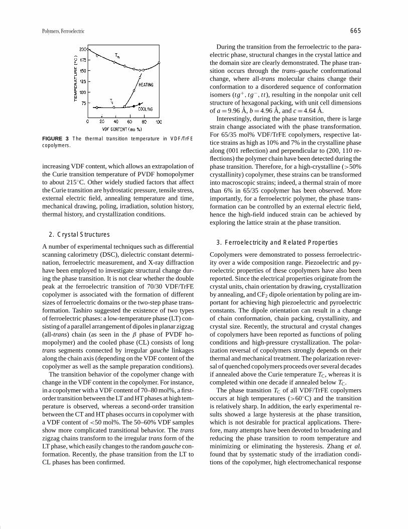
P1: GPB/GLT P2: GQT Final Pages
Encyclopedia of Physical Science and Technology en012f-594 July 26, 2001 11:9
Polymers, Ferroelectric 665
FIGURE 3 The thermal transition temperature in VDF/TrFEcopolymers.
increasing VDF content, which allows an extrapolation ofthe Curie transition temperature of PVDF homopolymerto about 215◦C. Other widely studied factors that affectthe Curie transition are hydrostatic pressure, tensile stress,external electric field, annealing temperature and time,mechanical drawing, poling, irradiation, solution history,thermal history, and crystallization conditions.
2. Crystal Structures
A number of experimental techniques such as differentialscanning calorimetry (DSC), dielectric constant determi-nation, ferroelectric measurement, and X-ray diffractionhave been employed to investigate structural change dur-ing the phase transition. It is not clear whether the doublepeak at the ferroelectric transition of 70/30 VDF/TrFEcopolymer is associated with the formation of differentsizes of ferroelectric domains or the two-step phase trans-formation. Tashiro suggested the existence of two typesof ferroelectric phases: a low-temperature phase (LT) con-sisting of a parallel arrangement of dipoles in planar zigzag(all-trans) chain (as seen in the β phase of PVDF ho-mopolymer) and the cooled phase (CL) consists of longtrans segments connected by irregular gauche linkagesalong the chain axis (depending on the VDF content of thecopolymer as well as the sample preparation conditions).
The transition behavior of the copolymer change withchange in the VDF content in the copolymer. For instance,in a copolymer with a VDF content of 70–80 mol%, a first-order transition between the LT and HT phases at high tem-perature is observed, whereas a second-order transitionbetween the CT and HT phases occurrs in copolymer witha VDF content of <50 mol%. The 50–60% VDF samplesshow more complicated transitional behavior. The transzigzag chains transform to the irregular trans form of theLT phase, which easily changes to the random gauche con-formation. Recently, the phase transition from the LT toCL phases has been confirmed.
During the transition from the ferroelectric to the para-electric phase, structural changes in the crystal lattice andthe domain size are clearly demonstrated. The phase tran-sition occurs through the trans–gauche conformationalchange, where all-trans molecular chains change theirconformation to a disordered sequence of conformationisomers (tg+, tg−, t t), resulting in the nonpolar unit cellstructure of hexagonal packing, with unit cell dimensionsof a = 9.96 A, b = 4.96 A, and c = 4.64 A.
Interestingly, during the phase transition, there is largestrain change associated with the phase transformation.For 65/35 mol% VDF/TrFE copolymers, respective lat-tice strains as high as 10% and 7% in the crystalline phasealong (001 reflection) and perpendicular to (200, 110 re-flections) the polymer chain have been detected during thephase transition. Therefore, for a high-crystalline (>50%crystallinity) copolymer, these strains can be transformedinto macroscopic strains; indeed, a thermal strain of morethan 6% in 65/35 copolymer has been observed. Moreimportantly, for a ferroelectric polymer, the phase trans-formation can be controlled by an external electric field,hence the high-field induced strain can be achieved byexploring the lattice strain at the phase transition.
3. Ferroelectricity and Related Properties
Copolymers were demonstrated to possess ferroelectric-ity over a wide composition range. Piezoelectric and py-roelectric properties of these copolymers have also beenreported. Since the electrical properties originate from thecrystal units, chain orientation by drawing, crystallizationby annealing, and CF2 dipole orientation by poling are im-portant for achieving high piezoelectric and pyroelectricconstants. The dipole orientation can result in a changeof chain conformation, chain packing, crystallinity, andcrystal size. Recently, the structural and crystal changesof copolymers have been reported as functions of polingconditions and high-pressure crystallization. The polar-ization reversal of copolymers strongly depends on theirthermal and mechanical treatment. The polarization rever-sal of quenched copolymers proceeds over several decadesif annealed above the Curie temperature TC, whereas it iscompleted within one decade if annealed below TC.
The phase transition TC of all VDF/TrFE copolymersoccurs at high temperatures (>60◦C) and the transitionis relatively sharp. In addition, the early experimental re-sults showed a large hysteresis at the phase transition,which is not desirable for practical applications. There-fore, many attempts have been devoted to broadening andreducing the phase transition to room temperature andminimizing or eliminating the hysteresis. Zhang et al.found that by systematic study of the irradiation condi-tions of the copolymer, high electromechanical response
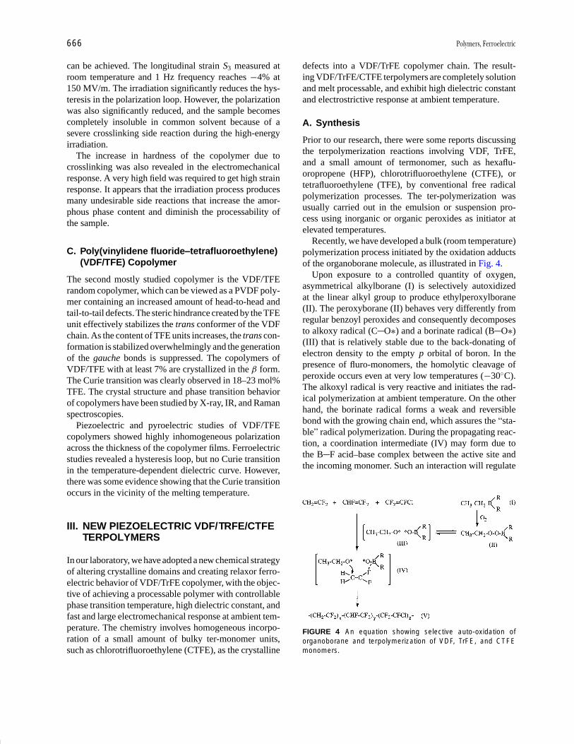
P1: GPB/GLT P2: GQT Final Pages
Encyclopedia of Physical Science and Technology en012f-594 July 26, 2001 11:9
666 Polymers, Ferroelectric
can be achieved. The longitudinal strain S3 measured atroom temperature and 1 Hz frequency reaches −4% at150 MV/m. The irradiation significantly reduces the hys-teresis in the polarization loop. However, the polarizationwas also significantly reduced, and the sample becomescompletely insoluble in common solvent because of asevere crosslinking side reaction during the high-energyirradiation.
The increase in hardness of the copolymer due tocrosslinking was also revealed in the electromechanicalresponse. A very high field was required to get high strainresponse. It appears that the irradiation process producesmany undesirable side reactions that increase the amor-phous phase content and diminish the processability ofthe sample.
C. Poly(vinylidene fluoride–tetrafluoroethylene)(VDF/TFE) Copolymer
The second mostly studied copolymer is the VDF/TFErandom copolymer, which can be viewed as a PVDF poly-mer containing an increased amount of head-to-head andtail-to-tail defects. The steric hindrance created by the TFEunit effectively stabilizes the trans conformer of the VDFchain. As the content of TFE units increases, the trans con-formation is stabilized overwhelmingly and the generationof the gauche bonds is suppressed. The copolymers ofVDF/TFE with at least 7% are crystallized in the β form.The Curie transition was clearly observed in 18–23 mol%TFE. The crystal structure and phase transition behaviorof copolymers have been studied by X-ray, IR, and Ramanspectroscopies.
Piezoelectric and pyroelectric studies of VDF/TFEcopolymers showed highly inhomogeneous polarizationacross the thickness of the copolymer films. Ferroelectricstudies revealed a hysteresis loop, but no Curie transitionin the temperature-dependent dielectric curve. However,there was some evidence showing that the Curie transitionoccurs in the vicinity of the melting temperature.
III. NEW PIEZOELECTRIC VDF/TRFE/CTFETERPOLYMERS
In our laboratory, we have adopted a new chemical strategyof altering crystalline domains and creating relaxor ferro-electric behavior of VDF/TrFE copolymer, with the objec-tive of achieving a processable polymer with controllablephase transition temperature, high dielectric constant, andfast and large electromechanical response at ambient tem-perature. The chemistry involves homogeneous incorpo-ration of a small amount of bulky ter-monomer units,such as chlorotrifluoroethylene (CTFE), as the crystalline
defects into a VDF/TrFE copolymer chain. The result-ing VDF/TrFE/CTFE terpolymers are completely solutionand melt processable, and exhibit high dielectric constantand electrostrictive response at ambient temperature.
A. Synthesis
Prior to our research, there were some reports discussingthe terpolymerization reactions involving VDF, TrFE,and a small amount of termonomer, such as hexaflu-oropropene (HFP), chlorotrifluoroethylene (CTFE), ortetrafluoroethylene (TFE), by conventional free radicalpolymerization processes. The ter-polymerization wasusually carried out in the emulsion or suspension pro-cess using inorganic or organic peroxides as initiator atelevated temperatures.
Recently, we have developed a bulk (room temperature)polymerization process initiated by the oxidation adductsof the organoborane molecule, as illustrated in Fig. 4.
Upon exposure to a controlled quantity of oxygen,asymmetrical alkylborane (I) is selectively autoxidizedat the linear alkyl group to produce ethylperoxylborane(II). The peroxyborane (II) behaves very differently fromregular benzoyl peroxides and consequently decomposesto alkoxy radical (C O∗) and a borinate radical (B O∗)(III) that is relatively stable due to the back-donating ofelectron density to the empty p orbital of boron. In thepresence of fluro-monomers, the homolytic cleavage ofperoxide occurs even at very low temperatures (−30◦C).The alkoxyl radical is very reactive and initiates the rad-ical polymerization at ambient temperature. On the otherhand, the borinate radical forms a weak and reversiblebond with the growing chain end, which assures the “sta-ble” radical polymerization. During the propagating reac-tion, a coordination intermediate (IV) may form due tothe B F acid–base complex between the active site andthe incoming monomer. Such an interaction will regulate
FIGURE 4 An equation showing selective auto-oxidation oforganoborane and terpolymerization of VDF, TrFE, and CTFEmonomers.
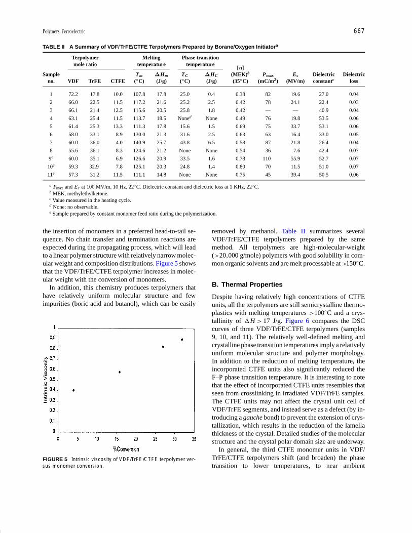
P1: GPB/GLT P2: GQT Final Pages
Encyclopedia of Physical Science and Technology en012f-594 July 26, 2001 11:9
Polymers, Ferroelectric 667
TABLE II A Summary of VDF/TrFE/CTFE Terpolymers Prepared by Borane/Oxygen Initiatora
Terpolymer Melting Phase transitionmole ratio temperature temperature
[η]Sample Tm ∆Hm TC ∆HC (MEK)b Pmax Ec Dielectric Dielectric
no. VDF TrFE CTFE (◦C) (J/g) (◦C) (J/g) (35◦C) (mC/m2) (MV/m) constantc loss
1 72.2 17.8 10.0 107.8 17.8 25.0 0.4 0.38 82 19.6 27.0 0.04
2 66.0 22.5 11.5 117.2 21.6 25.2 2.5 0.42 78 24.1 22.4 0.03
3 66.1 21.4 12.5 115.6 20.5 25.8 1.8 0.42 — — 40.9 0.04
4 63.1 25.4 11.5 113.7 18.5 Noned None 0.49 76 19.8 53.5 0.06
5 61.4 25.3 13.3 111.3 17.8 15.6 1.5 0.69 75 33.7 53.1 0.06
6 58.0 33.1 8.9 130.0 21.3 31.6 2.5 0.63 63 16.4 33.0 0.05
7 60.0 36.0 4.0 140.9 25.7 43.8 6.5 0.58 87 21.8 26.4 0.04
8 55.6 36.1 8.3 124.6 21.2 None None 0.54 36 7.6 42.4 0.07
9e 60.0 35.1 6.9 126.6 20.9 33.5 1.6 0.78 110 55.9 52.7 0.07
10e 59.3 32.9 7.8 125.1 20.3 24.8 1.4 0.80 70 11.5 51.0 0.07
11e 57.3 31.2 11.5 111.1 14.8 None None 0.75 45 39.4 50.5 0.06
a Pmax and Ec at 100 MV/m, 10 Hz, 22◦C. Dielectric constant and dielectric loss at 1 KHz, 22◦C.b MEK, methylethylketone.c Value measured in the heating cycle.d None: no observable.e Sample prepared by constant monomer feed ratio during the polymerization.
the insertion of monomers in a preferred head-to-tail se-quence. No chain transfer and termination reactions areexpected during the propagating process, which will leadto a linear polymer structure with relatively narrow molec-ular weight and composition distributions. Figure 5 showsthat the VDF/TrFE/CTFE terpolymer increases in molec-ular weight with the conversion of monomers.
In addition, this chemistry produces terpolymers thathave relatively uniform molecular structure and fewimpurities (boric acid and butanol), which can be easily
FIGURE 5 Intrinsic viscosity of VDF/TrFE/CTFE terpolymer ver-sus monomer conversion.
removed by methanol. Table II summarizes severalVDF/TrFE/CTFE terpolymers prepared by the samemethod. All terpolymers are high-molecular-weight(>20,000 g/mole) polymers with good solubility in com-mon organic solvents and are melt processable at >150◦C.
B. Thermal Properties
Despite having relatively high concentrations of CTFEunits, all the terpolymers are still semicrystalline thermo-plastics with melting temperatures >100◦C and a crys-tallinity of �H > 17 J/g. Figure 6 compares the DSCcurves of three VDF/TrFE/CTFE terpolymers (samples9, 10, and 11). The relatively well-defined melting andcrystalline phase transition temperatures imply a relativelyuniform molecular structure and polymer morphology.In addition to the reduction of melting temperature, theincorporated CTFE units also significantly reduced theF–P phase transition temperature. It is interesting to notethat the effect of incorporated CTFE units resembles thatseen from crosslinking in irradiated VDF/TrFE samples.The CTFE units may not affect the crystal unit cell ofVDF/TrFE segments, and instead serve as a defect (by in-troducing a gauche bond) to prevent the extension of crys-tallization, which results in the reduction of the lamellathickness of the crystal. Detailed studies of the molecularstructure and the crystal polar domain size are underway.
In general, the third CTFE monomer units in VDF/TrFE/CTFE terpolymers shift (and broaden) the phasetransition to lower temperatures, to near ambient

P1: GPB/GLT P2: GQT Final Pages
Encyclopedia of Physical Science and Technology en012f-594 July 26, 2001 11:9
668 Polymers, Ferroelectric
FIGURE 6 DSC comparison of three VDF/TrFE/CTFE terpolymers: (a) sample 9, (b) sample 10, and (c) sample 11in Table II.
temperature for samples 1, 2, 3, and 10, and almostdisappearing for samples 4, 8, and 11. That indicatesa very small energy barrier in the phase transition andimplies a smaller crystalline domain. The results areconsistent with the electric responses of the terpolymerunder an electric field.
C. Electric Properties
For electrical measurements, polymer films (∼30 µmthickness) were prepared either by solution casting ona glass slide from N ,N -dimethylformamide solutioncontaining 8–10 wt% polymer or melt-pressing polymerpowder at 200◦C. The polymer films were annealed at110◦C under vacuum for 5 hr. Gold (<1µm thickness)was sputtered on both surfaces of the polymer film. Thedielectric constant was measured by an HP multifreque-ncy LCR meter equipped with a temperature chamber.Figure 7 shows the dielectric constant of 59.3/32.9/7.8VDF/TrFE/CTFE terpolymer (sample 10) and 57.3/31.2/11.5 VDF/TrFE/CTFE terpolymer (sample 11) duringthe heating–cooling cycles.
In general, the dielectric constant hysteresis during theheating–cooling cycles is very small, and the dielectricpeak appears near the ambient temperature, well belowthe dielectric peak observed in 55/45 VDF/TrFE copoly-mer (>60◦C) with a big hysteresis loop. Diffuse dielectricpeaks and peaks shifting toward higher temperatures as
the frequency increases are common features of relaxorferroelectrics.
As shown in Table II, most of the terpolymers showhigh dielectric constants at ambient temperature. Samples4 and 5 exhibit dielectric constants as high as 53.5 and 53.1(1 kHz), respectively, at 22◦C. In sharp contrast, prior re-search reported that high dielectric constants (>25) onlyexisted in the VDF/TrFE/CTFE terpolymers with a narrowrange (18–22%) of TrFE content. In addition, the mechan-ical stretching of the polymer film, usually very importantfor increasing the dielectric constant in VDF/TrFE copoly-mers, is not necessary in these terpolymers. The effectiveorientation of dipoles under an electric field may be at-tributed to the low phase transition energy which occursat near-ambient temperature.
The polarization hysteresis loop was measured by aSawyer–Tower circuit with a frequency range between1 and 10 Hz. Figure 8 compares the polarization hys-teresis loops of two terpolymers (samples 2 and 8) anda 55/45 VDF/TrFE copolymer. Both terpolymers showsignificantly smaller hysteresis than the 55/45 copolymer,which has the narrowest polarization hysteresis loop ob-served in the copolymer samples. Sample 2 (VDF/TrFE/CTFE = 66/22.5/11.5 mole ratio) maintains a high polar-ization level (Pmax = 78 mC/m2 at E = 100 MV/m) andreduces both a coercive field (17.3 MV/m at P = 0) andremanent polarization (25.2 mC/m2 at E = 0). Sample 8(VDF/TrFE/CTFE = 55.6/36.1/8.3 mole ratio) exhibits a
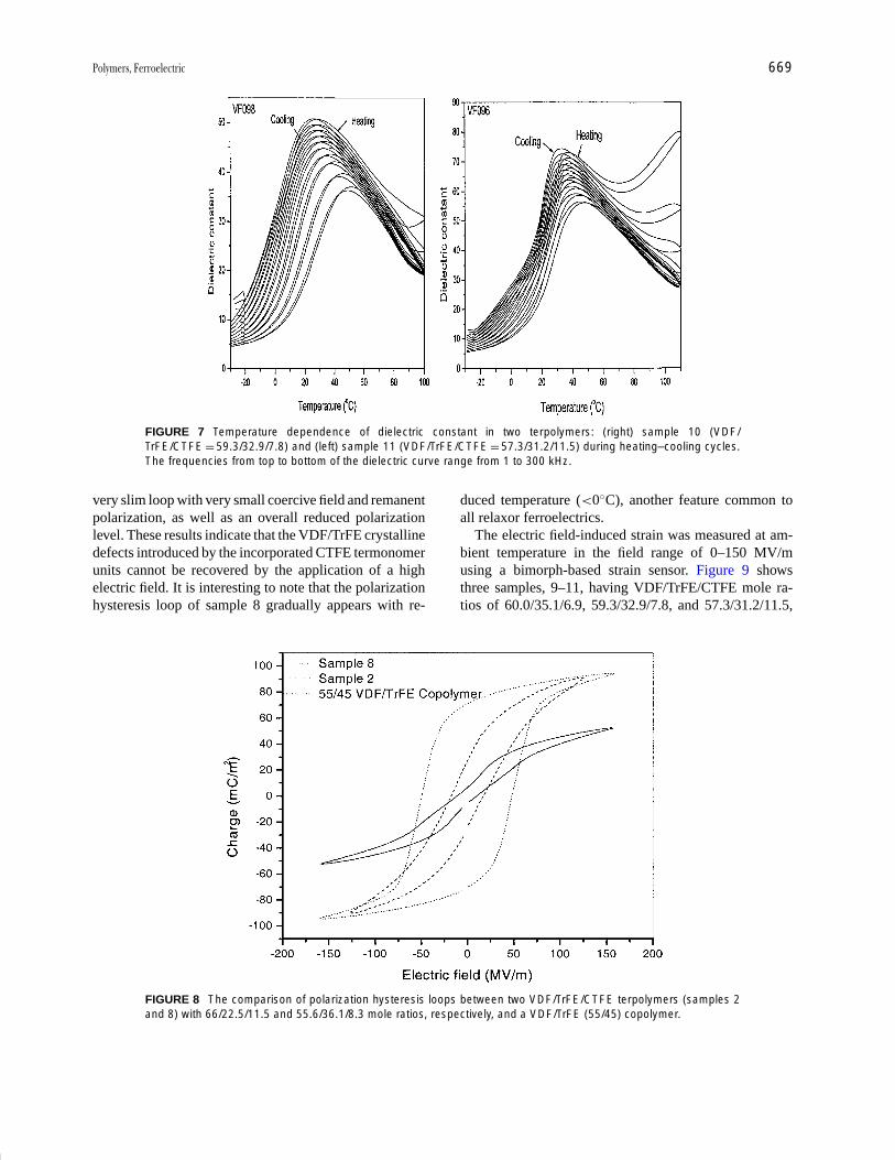
P1: GPB/GLT P2: GQT Final Pages
Encyclopedia of Physical Science and Technology en012f-594 July 26, 2001 11:9
Polymers, Ferroelectric 669
FIGURE 7 Temperature dependence of dielectric constant in two terpolymers: (right) sample 10 (VDF/TrFE/CTFE = 59.3/32.9/7.8) and (left) sample 11 (VDF/TrFE/CTFE = 57.3/31.2/11.5) during heating–cooling cycles.The frequencies from top to bottom of the dielectric curve range from 1 to 300 kHz.
very slim loop with very small coercive field and remanentpolarization, as well as an overall reduced polarizationlevel. These results indicate that the VDF/TrFE crystallinedefects introduced by the incorporated CTFE termonomerunits cannot be recovered by the application of a highelectric field. It is interesting to note that the polarizationhysteresis loop of sample 8 gradually appears with re-
FIGURE 8 The comparison of polarization hysteresis loops between two VDF/TrFE/CTFE terpolymers (samples 2and 8) with 66/22.5/11.5 and 55.6/36.1/8.3 mole ratios, respectively, and a VDF/TrFE (55/45) copolymer.
duced temperature (<0◦C), another feature common toall relaxor ferroelectrics.
The electric field-induced strain was measured at am-bient temperature in the field range of 0–150 MV/musing a bimorph-based strain sensor. Figure 9 showsthree samples, 9–11, having VDF/TrFE/CTFE mole ra-tios of 60.0/35.1/6.9, 59.3/32.9/7.8, and 57.3/31.2/11.5,
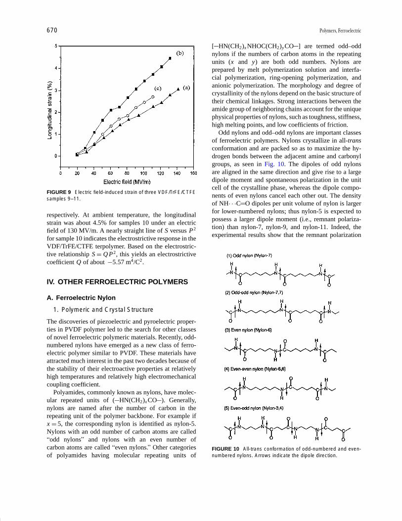
P1: GPB/GLT P2: GQT Final Pages
Encyclopedia of Physical Science and Technology en012f-594 July 26, 2001 11:9
670 Polymers, Ferroelectric
FIGURE 9 Electric field-induced strain of three VDF/TrFE/CTFEsamples 9–11.
respectively. At ambient temperature, the longitudinalstrain was about 4.5% for samples 10 under an electricfield of 130 MV/m. A nearly straight line of S versus P2
for sample 10 indicates the electrostrictive response in theVDF/TrFE/CTFE terpolymer. Based on the electrostric-tive relationship S = Q P2, this yields an electrostrictivecoefficient Q of about −5.57 m4/C2.
IV. OTHER FERROELECTRIC POLYMERS
A. Ferroelectric Nylon
1. Polymeric and Crystal Structure
The discoveries of piezoelectric and pyroelectric proper-ties in PVDF polymer led to the search for other classesof novel ferroelectric polymeric materials. Recently, odd-numbered nylons have emerged as a new class of ferro-electric polymer similar to PVDF. These materials haveattracted much interest in the past two decades because ofthe stability of their electroactive properties at relativelyhigh temperatures and relatively high electromechanicalcoupling coefficient.
Polyamides, commonly known as nylons, have molec-ular repeated units of ( HN(CH2)x CO ). Generally,nylons are named after the number of carbon in therepeating unit of the polymer backbone. For example ifx = 5, the corresponding nylon is identified as nylon-5.Nylons with an odd number of carbon atoms are called“odd nylons” and nylons with an even number ofcarbon atoms are called “even nylons.” Other categoriesof polyamides having molecular repeating units of
[ HN(CH2)x NHOC(CH2)yCO ] are termed odd–oddnylons if the numbers of carbon atoms in the repeatingunits (x and y) are both odd numbers. Nylons areprepared by melt polymerization solution and interfa-cial polymerization, ring-opening polymerization, andanionic polymerization. The morphology and degree ofcrystallinity of the nylons depend on the basic structure oftheir chemical linkages. Strong interactions between theamide group of neighboring chains account for the uniquephysical properties of nylons, such as toughness, stiffness,high melting points, and low coefficients of friction.
Odd nylons and odd–odd nylons are important classesof ferroelectric polymers. Nylons crystallize in all-transconformation and are packed so as to maximize the hy-drogen bonds between the adjacent amine and carbonylgroups, as seen in Fig. 10. The dipoles of odd nylonsare aligned in the same direction and give rise to a largedipole moment and spontaneous polarization in the unitcell of the crystalline phase, whereas the dipole compo-nents of even nylons cancel each other out. The densityof NH· · ·C O dipoles per unit volume of nylon is largerfor lower-numbered nylons; thus nylon-5 is expected topossess a larger dipole moment (i.e., remnant polariza-tion) than nylon-7, nylon-9, and nylon-11. Indeed, theexperimental results show that the remnant polarization
FIGURE 10 All-trans conformation of odd-numbered and even-numbered nylons. Arrows indicate the dipole direction.

P1: GPB/GLT P2: GQT Final Pages
Encyclopedia of Physical Science and Technology en012f-594 July 26, 2001 11:9
Polymers, Ferroelectric 671
of nylon-5 is ∼135 mC/m2. Odd-numbered nylons havepolymorphs. Nylon-11 has at least five different crystalstructures: triclinic α form I, monoclinic form II, pseudo-hexagonal γ form III, δ′ phase, γ ′ and phase. The α form ofnylon-11 is polar in nature, with dipoles that are hydrogen-bonded and aligned in the same direction, whereas theγ form is nonpolar and has amide groups that lie in theplane perpendicular to the chain axis. The crystal phasetransformation of nylon-11 occurs between a triclinic α
form and a pseudo-hexagonal γ form at high tempera-ture (>90◦C) through the randomization of the hydrogenbonding. Polymorphs of nylon-9, nylon-5,7, and nylon-7,7 have also been prepared. The α form seems to be themost common polymorph in many odd-numbered nylons.
2. Ferroelectricity and Related Properties
Nylons exhibit very interesting dielectric behavior in thatthe dielectric constant changes significantly with changesin temperature and frequency. The dielectric constants ofpoled and annealed nylons are relatively low (about 2.5–3)at various frequencies below 0◦C, and increase rapidlyabove the glass transition. The peak position, magnitudeof dielectric constant, and relaxation process in nylonschange with poling conditions and the presence of ab-sorbed water. Several articles have been focused on thehigh-frequency properties that are of interest for ultrasonictransducers.
The pyroelectricity and piezoelectricity of the α and γ
phases of nylon-11 films with variation of poling condi-tions have been reported. The γ phase nylon films showmuch higher piezoelectric response than α-phase filmsunder the same poling conditions. This characteristic dif-ference was interpreted as the breaking and re-forming ofhydrogen bonds under a high electric field. The γ phasehas a more regular arrangement of dipoles and has strongerhydrogen bonding, and thus is more strongly influencedby an applied electric field. However, it is found that amixture of α phase and γ phase, rather than pure α phaseor γ phase, has the highest piezoelectric constants. Thepiezoelectricity and pyroelectricity of odd nylons werealso affected by anisotropy, absorbed water, orientation,and annealing temperature.
Ferroelectric properties of nylons have been investi-gated by several research groups. Polarization reversalwas found to be complete in a few tens of millisecondsunder 140 MV/m at 20◦C. This fast polarization reversaland the rectangular D–E hysteresis loop are evidence of thedipoles’ origin. The effect of annealing on the ferroelectricbehavior of nylon-11 and nylon-7 has been investigated.The remanent polarization decreases with increasing an-nealing temperature and disappears at an annealing tem-perature of 185◦C, whereas the coercive field increases as
annealing temperature increases, indicating the rearrange-ment of the hydrogen bonding structure. The mechanismof ferroelectric polarization in odd nylons has not been ad-dressed, except for nylon-11. The ferroelectricity of polednylon-11 is related to the hydrogen bond breaking, fol-lowed by the reorientation of the amide groups towardthe electric field’s direction and the re-forming of hydro-gen bonds in a new direction. The orientation is retainedin the glassy state below Tg even after the electric fieldis removed. Ferroelectricity has also been observed inpolyamides containing m-xylylenediamine, aliphatic di-carboxylic acids, and fluorinated odd–odd nylons.
Ferroelectricity in aliphatic odd nylons has beenreported recently. Unlike nylons with ring systems, inwhich the ferroelectric nature arises from the orientationof the amide dipoles in the amorphous region, the fer-roelectric polarization of aliphatic odd nylons originatesfrom the crystalline phases. A slightly higher density ofamide dipoles contributes to a larger value for the rema-nent polarization, as seen in other nylon systems. Recently,a new class of ferroelectric and piezoelectric polymers,nylon-11/PVDF laminated films prepared by a co-melt-pressing method, has been reported. The laminated filmsexhibit a typical ferroelectric hysteresis loop with highremanent polarization, higher than that observed in PVDFhomopolymers or nylon-11 under the same measurementconditions. The film’s piezoelectric stress constant (d31 =41 pC/N) and piezoelectric strain constant (e31 = 109 mC/m2) are significantly higher than those of PVDFand nylon-11. Another new class of ferroelectric polya-mides recently reported is the ferroelectric polyamideblends. The D–E hysteresis curves were observedin all blends of nylon 6I/6T copolymers (6 = hexamethy-lenediamine, I = isoththalic acid, T = terephthalic acid)and m-xylylenediamine-6 (MXD6). It was concludedthat the intermolecular exchange of hydrogen bonding inthe amide groups is responsible for the ferroelectricity.
B. Cyanopolymers
Cyanopolymers discussed here include polyacrylonitriles(PAN), poly(vinyl cyanide), and cyanocopolymers. Thecyano group (C CN) has the unique feature of a largedipole moment (3.5 D) and the ability to form complexeswith transition metals. The polymerization can occurthrough free radical and ionic polymerization, leadingto nonstereoregular (atactic) cyano groups in the poly-mer structure. Thus, cyanopolymers have no clear meltingtemperature because of their high cohesive force and lowthermal stability. It has been accepted that the strong in-teraction and repulsion of the cyano groups force poly-mer chains to adopt a helical conformation. However, theall-trans conformation is more stable.

P1: GPB/GLT P2: GQT Final Pages
Encyclopedia of Physical Science and Technology en012f-594 July 26, 2001 11:9
672 Polymers, Ferroelectric
The ferroelectricity of poled and annealed PAN has beenstudied by X-ray and IR spectroscopy. It is believed thatthe ferroelectricity of PAN is related to the dipole ori-entation and kinking of the chain above the glass transi-tion temperature. The piezoelectric and pyroelectric prop-erties of PAN were initially studied by Ueda and Carr,and were proved by Von Berlepsch using copolymer withmethylacrylate. The D–E hysteresis loop of a stretchedfilm of this copolymer has been measured at 68◦C, whichis below the glass transition temperature. The copolymershowed very low remanent polarization and high coercivefield at low temperature. However, an alternating copoly-mer of PAN, poly(allycyanide[35%]/acrylonitrile[65%]),showed very high remanent polarization, 200–700 mC/m2
at 105◦C.Another alternating copolymer that has received more
attention as an amorphous copolymer is vinylidenecyanide/vinyl acetate copolymer. The dipole moment ofthe repeating unit is 4.5 D in trans conformation, thuscontributing to a large piezoelectric constant after poling.The piezoelectricity (d31) of drawn and poled films iscomparable to that of PVDF in the temperature range 20–100◦C. Interestingly, this copolymer shows a very largedielectric strength of more than 100, one of the largestvalues among polymers. It is concluded that the largedielectric relaxation strength originates from the coopera-tive motion of 10 or more CN dipoles. The exceptionallyhigh dielectric peaks occur near the glass transitiontemperature, similar to a ferroelectric transition. A mostunique feature of this copolymer is its low density, whichresults in low acoustic impedance, close to the levels seenin water and the human body. This makes this copolymervery useful in medical applications.
C. Polyureas and Polythioureas
Polyureas and polythioureas are amino resins, and are ther-mosetting polymers. They are usually synthesized by con-densation polymerization, and their products are mostlyin the form of powder. The preparation of thin films wasnot possible due to their insolubility until a technique ofvapor deposition polymerization was developed. The syn-thesis and characterization of different kinds of thin-filmpolyureas have been reported. A typical polymerizationconsists in vapor deposition of monomers onto the sur-face of a substrate in a vacuum chamber. The monomersdiffuse on the surface and react with each other to formurea bonds between an amino (NH2) group and an iso-cyanate (CNO) group. The urea bond (NHCONH) has adipole moment of 4.9 D and is responsible for high piezo-electric and pyroelectric properties.
The dielectric constants of aromatic polyureas [P(4,4′-diphenylmethane diisocyanate (MDI)/4,4′-diamino diph-
enylmethane (MDA)] have been reported. The dielectricconstant of MDA-rich films of poled and annealedP(MDA/MDI) are relatively constant up to 200◦C,whereas the MDI-rich films have a low dielectric constantbut show good stability up to 200◦C. The dielectricconstants of the balanced stoichiometric films increasewith increasing temperatures above 100◦C. Pyroelectricand piezoelectric constants are also large for the balancedcomposition films. This is due to the fact that a crosslinkednetwork structure does not form in balanced film the wayit does in unbalanced films. The high-molecular-weightmolecules are oriented or crystallized in a local regionunder a high poling field and form a semicrystalline struc-ture; thus, stabilized residual polarization is produced andgives rise to high piezoelectric and pyroelectric constants.
The pyroelectric and piezoelectric properties of alip-hatic polyureas display similar features to those seen innylons, i.e., there is no observation of these activities if thenumber of carbon atoms between the urea bond is even.This is because alternating urea bond dipoles arrange inantiparallel direction, and the dipole moments cancel out.Strong hydrogen bonds are possible in cases where theparallel orientation of dipoles in a planar zigzag chaingives rise to high glass transition and melting tempera-tures. Dielectric peaks above 125◦C have been observed inpoly(heptamethylene/nanomethyleneurea). The relativelylarge dielectric constant is believed to be related to thecrystal transition from the mobile dipole state to the rigiddipole state corresponding to the different hydrogen bond-ing states. The value of remanent polarization obtainedfrom D–E hysteresis of the same sample is as high as200–440 mC/m2 at 90◦C, which may be attributed to theeffect of the ionic currents of impurities. The remanent po-larization disappears above 110◦C, which suggests the re-arrangement of the hydrogen bonding at this temperature.
Polythioureas are known pyroelectric, pyroelectric,and ferroelectric polymers. Their chemical structure isH2N CS NH2. Ferroelectric thiourea polymers havebeen prepared by condensation reaction of thioureaand formaldehyde under different conditions. Thiourea[SC(NH2)2] has a large dipole moment of 5.4 D. Ferro-electricity in polythioureas was initially studied in 1978.The sharp dielectric constant of thiourea-formaldehyde(PTUBFB) observed at 145◦C is as high as 320. Recently,an odd-numbered aliphatic polythiourea, polythiourea-9,has been synthesized. The odd number of carbons waschosen to ensure a polar chain and polar packing. Largedielectric relaxation as well as a large dielectric constantwere observed in the glass transition region. Accordingto the theoretical data of Meakins et al., the dielectricrelaxation and dielectric loss increase with any increasein hydrogen bonding. As a result, the hydrogen-bondedthiourea dipoles in the intermolecular chains are easily
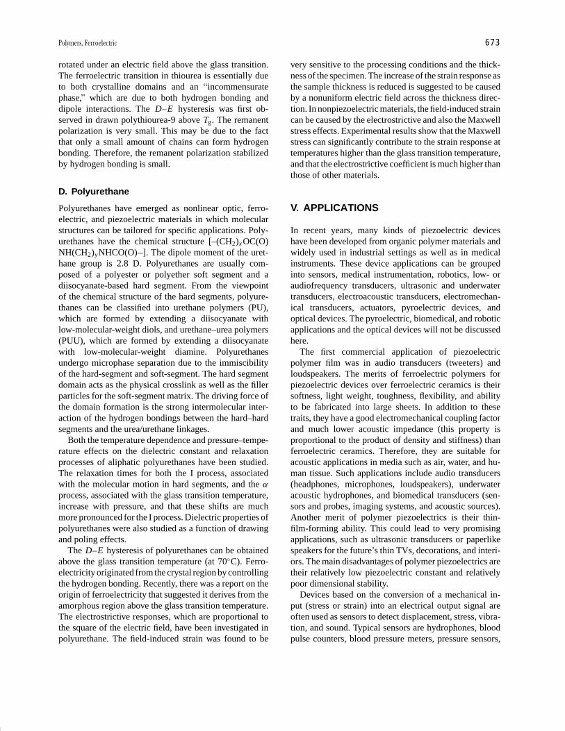
P1: GPB/GLT P2: GQT Final Pages
Encyclopedia of Physical Science and Technology en012f-594 July 26, 2001 11:9
Polymers, Ferroelectric 673
rotated under an electric field above the glass transition.The ferroelectric transition in thiourea is essentially dueto both crystalline domains and an “incommensuratephase,” which are due to both hydrogen bonding anddipole interactions. The D–E hysteresis was first ob-served in drawn polythiourea-9 above Tg. The remanentpolarization is very small. This may be due to the factthat only a small amount of chains can form hydrogenbonding. Therefore, the remanent polarization stabilizedby hydrogen bonding is small.
D. Polyurethane
Polyurethanes have emerged as nonlinear optic, ferro-electric, and piezoelectric materials in which molecularstructures can be tailored for specific applications. Poly-urethanes have the chemical structure [–(CH2)x OC(O)NH(CH2)yNHCO(O) ]. The dipole moment of the uret-hane group is 2.8 D. Polyurethanes are usually com-posed of a polyester or polyether soft segment and adiisocyanate-based hard segment. From the viewpointof the chemical structure of the hard segments, polyure-thanes can be classified into urethane polymers (PU),which are formed by extending a diisocyanate withlow-molecular-weight diols, and urethane–urea polymers(PUU), which are formed by extending a diisocyanatewith low-molecular-weight diamine. Polyurethanesundergo microphase separation due to the immiscibilityof the hard-segment and soft-segment. The hard segmentdomain acts as the physical crosslink as well as the fillerparticles for the soft-segment matrix. The driving force ofthe domain formation is the strong intermolecular inter-action of the hydrogen bondings between the hard–hardsegments and the urea/urethane linkages.
Both the temperature dependence and pressure–tempe-rature effects on the dielectric constant and relaxationprocesses of aliphatic polyurethanes have been studied.The relaxation times for both the I process, associatedwith the molecular motion in hard segments, and the α
process, associated with the glass transition temperature,increase with pressure, and that these shifts are muchmore pronounced for the I process. Dielectric properties ofpolyurethanes were also studied as a function of drawingand poling effects.
The D–E hysteresis of polyurethanes can be obtainedabove the glass transition temperature (at 70◦C). Ferro-electricity originated from the crystal region by controllingthe hydrogen bonding. Recently, there was a report on theorigin of ferroelectricity that suggested it derives from theamorphous region above the glass transition temperature.The electrostrictive responses, which are proportional tothe square of the electric field, have been investigated inpolyurethane. The field-induced strain was found to be
very sensitive to the processing conditions and the thick-ness of the specimen. The increase of the strain response asthe sample thickness is reduced is suggested to be causedby a nonuniform electric field across the thickness direc-tion. In nonpiezoelectric materials, the field-induced straincan be caused by the electrostrictive and also the Maxwellstress effects. Experimental results show that the Maxwellstress can significantly contribute to the strain response attemperatures higher than the glass transition temperature,and that the electrostrictive coefficient is much higher thanthose of other materials.
V. APPLICATIONS
In recent years, many kinds of piezoelectric deviceshave been developed from organic polymer materials andwidely used in industrial settings as well as in medicalinstruments. These device applications can be groupedinto sensors, medical instrumentation, robotics, low- oraudiofrequency transducers, ultrasonic and underwatertransducers, electroacoustic transducers, electromechan-ical transducers, actuators, pyroelectric devices, andoptical devices. The pyroelectric, biomedical, and roboticapplications and the optical devices will not be discussedhere.
The first commercial application of piezoelectricpolymer film was in audio transducers (tweeters) andloudspeakers. The merits of ferroelectric polymers forpiezoelectric devices over ferroelectric ceramics is theirsoftness, light weight, toughness, flexibility, and abilityto be fabricated into large sheets. In addition to thesetraits, they have a good electromechanical coupling factorand much lower acoustic impedance (this property isproportional to the product of density and stiffness) thanferroelectric ceramics. Therefore, they are suitable foracoustic applications in media such as air, water, and hu-man tissue. Such applications include audio transducers(headphones, microphones, loudspeakers), underwateracoustic hydrophones, and biomedical transducers (sen-sors and probes, imaging systems, and acoustic sources).Another merit of polymer piezoelectrics is their thin-film-forming ability. This could lead to very promisingapplications, such as ultrasonic transducers or paperlikespeakers for the future’s thin TVs, decorations, and interi-ors. The main disadvantages of polymer piezoelectrics aretheir relatively low piezoelectric constant and relativelypoor dimensional stability.
Devices based on the conversion of a mechanical in-put (stress or strain) into an electrical output signal areoften used as sensors to detect displacement, stress, vibra-tion, and sound. Typical sensors are hydrophones, bloodpulse counters, blood pressure meters, pressure sensors,
P1: GPB/GLT P2: GQT Final Pages
Encyclopedia of Physical Science and Technology en012f-594 July 26, 2001 11:9
674 Polymers, Ferroelectric
acceleration sensors, shock sensors, vibration sensors,touch sensors, microphones, antinoise sensors, and key-boards. Reverse devices, in which the input is an electricalsignal and the output is a mechanical signal, include po-sition controls, acoustic systems, and actuators.
SEE ALSO THE FOLLOWING ARTICLES
NONLINEAR OPTICAL PROCESSES • ORGANOMETALLIC
CHEMISTRY • POLYMERS, ELECTRONIC PROPERTIES •POLYMERS, SYNTHESIS • ULTRASONICS AND ACOUSTICS
BIBLIOGRAPHY
Brown, L. F., Scheinbeim, J. I., and Newman, B. A. (1995). Ferro-electrics 171, 321.
Chung, T. C., and Janvikul, W. (1999). J. Organomet. Chem. 581, 176.Cross, L. E. (1996). Ceram. Trans. 68, 15.Furukawa, T., Date, M., Fukada, E., Tajitsu, Y., and Chiba, A. (1980).
Jpn. J. Appl. Phys. 19, L109.Kawai, H. (1969). Jpn. J. Appl. Phys. 8, 1975.Lovinger, A. J. (1982). “Poly(vinylidene Fluoride),” In “Developments in
Crystalline Polymers,” Vol. 1, pp. 195–273 (Basett, D.C., ed.), AppliedScience, London.
Lovinger, A. J. (1983). Science 220, 1115.Nalwa, H. S. (1991). J. Macromol. Sci. Rev. Macromol. Chem. Phys.
C-31, (4), 341.Nalwa, H. S. (ed.). (1995). “Ferroelectric Polymers,” Marcel Dekker,
New York.Ueda, H., and Carr, S. H. (1984). Polymer J. 16, 661.Von Berlepsch, H., Kunstler, W., and Danz, R. (1988). Ferroelectrics
81, 353.Wang T. T., Herbert, J. M., and Glass A. M. (eds.). (1988). “The Ap-
plications of Ferroelectric Polymers,” Blackie, Chapman and Hall,Glasgow.
Zhang, Q. M., Bharti, V., and Zhao, X. (1998). Science 280,2102.
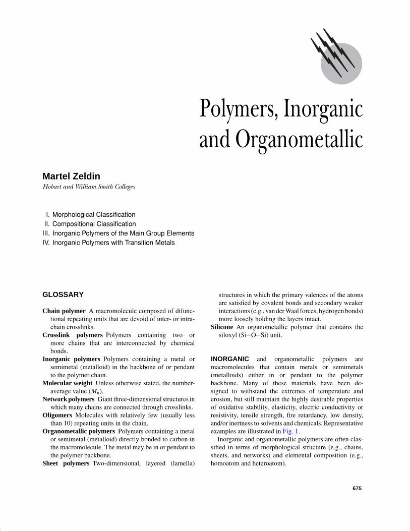
P1: GKY/MBQ P2: GLQ Final Pages Qu: 00, 00, 00, 00
Encyclopedia of Physical Science and Technology en012i-947 July 26, 2001 11:11
Polymers, Inorganicand Organometallic
Martel ZeldinHobart and William Smith Colleges
I. Morphological ClassificationII. Compositional Classification
III. Inorganic Polymers of the Main Group ElementsIV. Inorganic Polymers with Transition Metals
GLOSSARY
Chain polymer A macromolecule composed of difunc-tional repeating units that are devoid of inter- or intra-chain crosslinks.
Crosslink polymers Polymers containing two ormore chains that are interconnected by chemicalbonds.
Inorganic polymers Polymers containing a metal orsemimetal (metalloid) in the backbone of or pendantto the polymer chain.
Molecular weight Unless otherwise stated, the number-average value (Mn).
Network polymers Giant three-dimensional structures inwhich many chains are connected through crosslinks.
Oligomers Molecules with relatively few (usually lessthan 10) repeating units in the chain.
Organometallic polymers Polymers containing a metalor semimetal (metalloid) directly bonded to carbon inthe macromolecule. The metal may be in or pendant tothe polymer backbone.
Sheet polymers Two-dimensional, layered (lamella)
structures in which the primary valences of the atomsare satisfied by covalent bonds and secondary weakerinteractions (e.g., van der Waal forces, hydrogen bonds)more loosely holding the layers intact.
Silicone An organometallic polymer that contains thesiloxyl (Si O Si) unit.
INORGANIC and organometallic polymers aremacromolecules that contain metals or semimetals(metalloids) either in or pendant to the polymerbackbone. Many of these materials have been de-signed to withstand the extremes of temperature anderosion, but still maintain the highly desirable propertiesof oxidative stability, elasticity, electric conductivity orresistivity, tensile strength, fire retardancy, low density,and/or inertness to solvents and chemicals. Representativeexamples are illustrated in Fig. 1.
Inorganic and organometallic polymers are often clas-sified in terms of morphological structure (e.g., chains,sheets, and networks) and elemental composition (e.g.,homoatom and heteroatom).
675
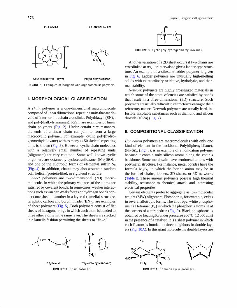
P1: GKY/MBQ P2: GLQ Final Pages
Encyclopedia of Physical Science and Technology en012i-947 July 26, 2001 11:11
676 Polymers, Inorganic and Organometallic
FIGURE 1 Examples of inorganic and organometallic polymers.
I. MORPHOLOGICAL CLASSIFICATION
A chain polymer is a one-dimensional macromoleculecomposed of linear difunctional repeating units that are de-void of inter- or intrachain crosslinks. Polythiazyl, (SN)x ,and poly(dialkylstannanes), R2Sn, are examples of linearchain polymers (Fig. 2). Under certain circumstances,the ends of a linear chain can join to form a largemacrocyclic polymer. For example, cyclic poly(hydro-genmethylsiloxane) with as many as 50 skeletal repeatingunits is known (Fig. 3). However, cyclic chain moleculeswith a relatively small number of repeating units(oligomers) are very common. Some well-known cyclicoligomers are octamethylcyclotetrasiloxane, (Me2SiO)4,and one of the allotropic forms of elemental sulfur, S8
(Fig. 4). In addition, chains may also assume a randomcoil, helical (protein-like), or rigid-rod structure.
Sheet polymers are two-dimensional (2D) macro-molecules in which the primary valences of the atoms aresatisfied by covalent bonds. In some cases, weaker interac-tions such as van der Waals forces or hydrogen bonds con-nect one sheet to another in a layered (lamella) structure.Graphitic carbon and boron nitride, (BN)x , are examplesof sheet polymers (Fig. 5). Both polymers consist of flatsheets of hexagonal rings in which each atom is bonded tothree other atoms in the same layer. The sheets are stackedin a lamella fashion permitting the sheets to “flake.”
FIGURE 2 Chain polymer.
FIGURE 3 Cyclic poly(hydrogenmethylsiloxane).
Another variation of a 2D sheet occurs if two chains arecrosslinked at regular intervals to give a ladder-type struc-ture. An example of a siloxane ladder polymer is givenin Fig. 6. Ladder polymers are unusually high-meltingsolids with extraordinary oxidative, hydrolytic, and ther-mal stability.
Network polymers are highly crosslinked materials inwhich some of the atom valencies are satisfied by bondsthat result in a three-dimensional (3D) structure. Suchpolymers are usually difficult to characterize owing to theirrefractory nature. Network polymers are usually hard, in-fusible, insoluble substances such as diamond and silicondioxide (silica) (Fig. 7).
II. COMPOSITIONAL CLASSIFICATION
Homoatom polymers are macromolecules with only onekind of element in the backbone. Poly(diphenylsilane),(Ph2Si)n (Fig. 8), is an example of a homoatom polymerbecause it contain only silicon atoms along the chain’sbackbone. Some metal salts have semimetal anions withpolymeric structure. For instance, metal borides have theformula Mx By in which the boride anion may be inthe form of chains, ladders, 2D sheets, or 3D networks(Table I). These anionic polymers possess high thermalstability, resistance to chemical attack, and interestingelectrical properties.
Certain elements prefer to aggregate as low-molecularweight (MW) oligomers. Phosphorus, for example, existsin several allotropic forms. The allotrope, white phospho-rus, is a tetramer (P4) in which the phosphorus atoms lie atthe corners of a tetrahedron (Fig. 9). Black phosphorus isobtained by heating P4 under pressure (200◦C, 12 000 atm)in the presence of a catalyst. It is a sheet polymer in whicheach P atom is bonded to three neighbors in double lay-ers (Fig. 10A). In this giant molecule the double layers are
FIGURE 4 Common cyclic polymers.

P1: GKY/MBQ P2: GLQ Final Pages
Encyclopedia of Physical Science and Technology en012i-947 July 26, 2001 11:11
Polymers, Inorganic and Organometallic 677
FIGURE 5 Graphite sheet polymer. In graphite (above), the Catoms are located at each vertex and the layers are staggered. Inboron nitride, the B and N atoms are located at alternate verticesand the layers are eclipsed.
stacked in a manner similar to graphite. In addition to flak-ing, black phosphorus is a good electrical conductor. Redphosphorus results from heating P4 at ∼400◦C in a sealedvessel. One crystalline form of red phosphorus (Hittorf’sphosphorus) has a linear tubular arrangement of eight Patoms in a pentagonal wedge structure (Fig. 10B).
Like phosphorus, elemental sulfur is a polyatomic,polymorphic substance. Oligomeric sulfur rings that con-tain from 6 to 12 sulfur atoms have been identified(Fig. 11). The orthorhombic form, α-S8, has the mostthermodynamically stable structure and exists as a yel-low crystalline solid consisting of eight-member puck-ered rings in a crown conformation stacked together in“crankcase” fashion. The chain polymer form of sulfurcalled catena or plastic sulfur is obtained by quenchingmolten S8 in water. If stretched, catena sulfur has a helicalpolymeric structure. Selenium forms polymers similar tothose of sulfur.
Heteroatom polymers contain a metal or semimetal inaddition to one or more other atoms (e.g., O, S, N, P, and C)in the polymer backbone. It is well-known that polymerstability and inertness increases when the heteroatom iselectron rich. Presumably, such atoms serve as electronsources toward low-lying vacant orbitals on the metal orsemimetal (Fig. 12). The resulting coordinate (dative) in-teraction generally decreases the nucleophilicity of themetal or semimetal thereby reducing the susceptibility ofthe polymer to attack by Lewis acids and bases. Further-
FIGURE 6 Poly(diphenylsiloxane) ladder polymer.
FIGURE 7 Network polymer (diamond and silica). In diamond,each atom is carbon; in silica, silicon is surrounded tetrahedrallyby four oxygen atoms.
more, the dative interaction tends to stabilize the polymertoward thermal degradation and aids in the regulation ofstructure, chain mobility, and interchain forces that en-hance useful dynamic–mechanical properties.
III. INORGANIC POLYMERS OFTHE MAIN GROUP ELEMENTS
A. Silicon-Based Polymers
1. Polysiloxanes (Silicones)
Polysiloxanes are chains, rings, ladders, and 3D networkpolymers that contain siloxane (Si O Si) bonds in thebackbone. The basic structural units of polysiloxanes are
Si
R
R
R O Si
R
R
O O Si
R
O
O O Si
O
O
O O
Monofunctional unit(end group)
Difunctional unit(linear backbone)
Trifunctional unit(crosslink)
Tetrafunctional unit(crosslink and network)
Chain polysiloxanes are composed of difunctionalunits. The framing groups (R) are either H or organicmoieties and the end groups are usually OR or a mono-functional siloxyl unit. Chain polysiloxanes such as poly-(dimethylsiloxane)s are synthesized by the hydrolysis ofdichlorodimethysilane [Eq. (1)].
FIGURE 8 Homoatom and heteroatom polymers.
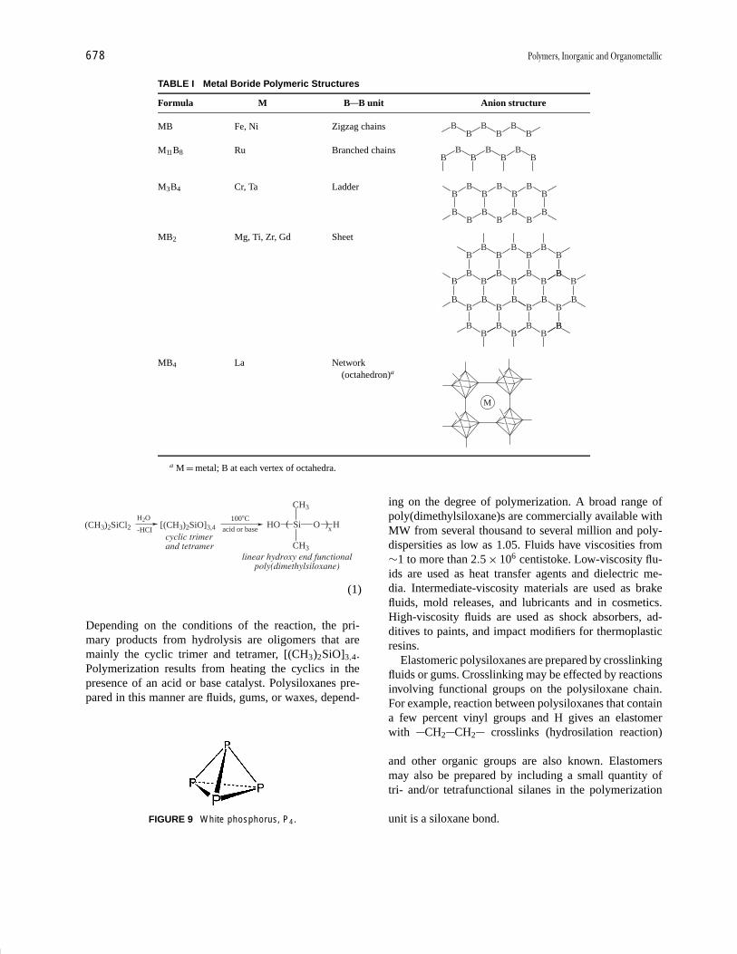
P1: GKY/MBQ P2: GLQ Final Pages
Encyclopedia of Physical Science and Technology en012i-947 July 26, 2001 11:11
678 Polymers, Inorganic and Organometallic
TABLE I Metal Boride Polymeric Structures
Formula M B B unit Anion structure
MB Fe, Ni Zigzag chains BB
BB
BB
M11B8 Ru Branched chains BB
BB
BBB
M3B4 Cr, Ta Ladder BB
BB
BBB
BB
BB
BBB
MB2 Mg, Ti, Zr, Gd SheetB
BB
BB
BB
BB
BB
BBB
B
BB
BB
BBB
BB
BB
BB
BB
BBB B
MB4 La Network(octahedron)a
M
a M = metal; B at each vertex of octahedra.
(CH3)2SiCl2H2O
-HCI[(CH3)2SiO]3,4 acid or base
100�Cx
( Si O ) H
CH3
CH3
cyclic trimerand tetramer
linear hydroxy end functionalpoly(dimethylsiloxane)
HO
(1)
Depending on the conditions of the reaction, the pri-mary products from hydrolysis are oligomers that aremainly the cyclic trimer and tetramer, [(CH3)2SiO]3,4.Polymerization results from heating the cyclics in thepresence of an acid or base catalyst. Polysiloxanes pre-pared in this manner are fluids, gums, or waxes, depend-
FIGURE 9 White phosphorus, P4.
ing on the degree of polymerization. A broad range ofpoly(dimethylsiloxane)s are commercially available withMW from several thousand to several million and poly-dispersities as low as 1.05. Fluids have viscosities from∼1 to more than 2.5 × 10⁶ centistoke. Low-viscosity flu-ids are used as heat transfer agents and dielectric me-dia. Intermediate-viscosity materials are used as brakefluids, mold releases, and lubricants and in cosmetics.High-viscosity fluids are used as shock absorbers, ad-ditives to paints, and impact modifiers for thermoplasticresins.
Elastomeric polysiloxanes are prepared by crosslinkingfluids or gums. Crosslinking may be effected by reactionsinvolving functional groups on the polysiloxane chain.For example, reaction between polysiloxanes that containa few percent vinyl groups and H gives an elastomerwith CH2 CH2 crosslinks (hydrosilation reaction)[Eq. (2)]. Crosslinks that contain ester, amide, urethane,and other organic groups are also known. Elastomersmay also be prepared by including a small quantity oftri- and/or tetrafunctional silanes in the polymerizationof cyclic oligomers [Eq. (3)]. In this case the crosslinkingunit is a siloxane bond.

P1: GKY/MBQ P2: GLQ Final Pages
Encyclopedia of Physical Science and Technology en012i-947 July 26, 2001 11:11
Polymers, Inorganic and Organometallic 679
FIGURE 10 Black and red phosphorus.
OSi
RO
C
C
HH
R
Pt Catalyst
Hydrosilation
CH H
CH H
H
OSi
OR
OSi
O
OSi
RO
H
(2)
[(CH3)2SiO]3,4 � CH3 O Si O CH3100�C
acid or base H )( O Si O Si O ( Si O ) Hb
CH3
CH3
CH3
CH3
a
H )( O Si O
CH3
CH3
c
O ( Si O ) Hd
CH3
CH3
Cyclic Oligomers
O
CH3
O
CH3
Tetramethoxysilane
Crosslinked Polymer
�CH3OH
(3)
Resins differ from elastomers in the proportion ofcrosslinks that are present. Highly crosslinked polysilox-anes are sometimes called T-resins. In general, T-resinsare prepared by the hydrolysis of tri- and tetrafunctionalsilanes. The resulting resins have a complex network struc-ture and are insoluble in common organic solvents. Underspecially controlled synthetic conditions, lower MW ma-terials containing ladder and polyhedral oligomeric silox-anes called silsesquioxanes (Fig. 13) are obtained that aresoluble in organic solvents. The resins are used as coatingsin microelectronic devices and binding agents in high-performance refractory materials.
FIGURE 11 Allotropic forms of elemental sulfur.
Polysiloxanes have many commercial and consumer ap-plications. Some of the uses of polysiloxane fluids, elas-tomers, and resins are summarized in Table II. Some of theimportant physical properties of polysiloxanes that lead toapplications are their low glass transition temperature Tg,low bulk viscosity, low thermal coefficient of viscosity,high gas permeability, low surface energy, and low sur-face tension.
2. Polysilanes
Polysilanes are chains, rings, and 3D network polymers ofsilicon that contain the Si Si bond in the polymer back-bone. The tetravalency of silicon is usually completed withH or organic groups. The basic structural unit of a polysi-lane is shown in Fig. 14.
There are several methods of polysilane synthesis:reductive or Wurtz coupling [Eq. (4)], dehydrogena-tive coupling [Eq. (5)], ring-opening polymerization ofcyclic silane oligomers [Eq. (6)], ring-opening of cyclicorganodisilanes [Eq. (7)], and polymerization of silylenes[Eq. (8)]:
n R2SiHal2 � 2n M ( )
R
Si n � 2n MHal
Hal � Cl, BrR � H, Organic (M � Na, Li) R
(4)
( )
R
Si n �
H
n RSiH3 catalyst
metallocenen H2 (5)
FIGURE 12 Coordinate (dative) bond.
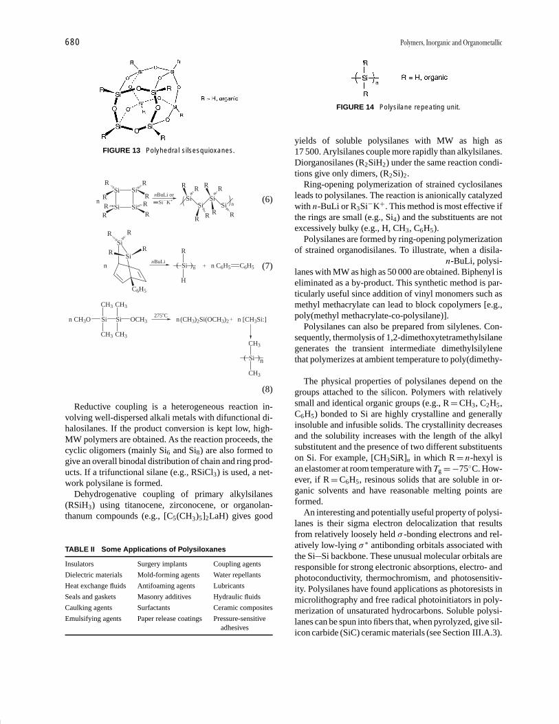
P1: GKY/MBQ P2: GLQ Final Pages
Encyclopedia of Physical Science and Technology en012i-947 July 26, 2001 11:11
680 Polymers, Inorganic and Organometallic
FIGURE 13 Polyhedral silsesquioxanes.
SiSi
Si
Si
R
R
R
R
R
R R
R
Si�K+nBuLi or
SiSi
Si
R
R
R
R
SiR R
RR
nn (6)
( )
R
Si n �
H
nBuLin C6H5 C6H5
SiR R
SiR R
n
C6H5
(7)
CH3O Si
CH3
CH3
Si
CH3
CH3
OCH3275�C
n (CH3)2n Si(OCH3)2� n [CH3Si:]
( )
CH3
Si n
CH3
(8)
Reductive coupling is a heterogeneous reaction in-volving well-dispersed alkali metals with difunctional di-halosilanes. If the product conversion is kept low, high-MW polymers are obtained. As the reaction proceeds, thecyclic oligomers (mainly Si6 and Si8) are also formed togive an overall binodal distribution of chain and ring prod-ucts. If a trifunctional silane (e.g., RSiCl3) is used, a net-work polysilane is formed.
Dehydrogenative coupling of primary alkylsilanes(RSiH3) using titanocene, zirconocene, or organolan-thanum compounds (e.g., [C5(CH3)5]2LaH) gives good
TABLE II Some Applications of Polysiloxanes
Insulators Surgery implants Coupling agents
Dielectric materials Mold-forming agents Water repellants
Heat exchange fluids Antifoaming agents Lubricants
Seals and gaskets Masonry additives Hydraulic fluids
Caulking agents Surfactants Ceramic composites
Emulsifying agents Paper release coatings Pressure-sensitiveadhesives
FIGURE 14 Polysilane repeating unit.
yields of soluble polysilanes with MW as high as17 500. Arylsilanes couple more rapidly than alkylsilanes.Diorganosilanes (R2SiH2) under the same reaction condi-tions give only dimers, (R2Si)2.
Ring-opening polymerization of strained cyclosilanesleads to polysilanes. The reaction is anionically catalyzedwith n-BuLi or R3Si−K+. This method is most effective ifthe rings are small (e.g., Si4) and the substituents are notexcessively bulky (e.g., H, CH3, C6H5).
Polysilanes are formed by ring-opening polymerizationof strained organodisilanes. To illustrate, when a disila-bicyclooctadiene [Eq. (7)] is treated with n-BuLi, polysi-lanes with MW as high as 50 000 are obtained. Biphenyl iseliminated as a by-product. This synthetic method is par-ticularly useful since addition of vinyl monomers such asmethyl methacrylate can lead to block copolymers [e.g.,poly(methyl methacrylate-co-polysilane)].
Polysilanes can also be prepared from silylenes. Con-sequently, thermolysis of 1,2-dimethoxytetramethylsilanegenerates the transient intermediate dimethylsilylenethat polymerizes at ambient temperature to poly(dimethy-silane) [Eq. (8)].
The physical properties of polysilanes depend on thegroups attached to the silicon. Polymers with relativelysmall and identical organic groups (e.g., R = CH3, C2H5,C6H5) bonded to Si are highly crystalline and generallyinsoluble and infusible solids. The crystallinity decreasesand the solubility increases with the length of the alkylsubstitutent and the presence of two different substituentson Si. For example, [CH3SiR]n in which R = n-hexyl isan elastomer at room temperature with Tg = −75◦C. How-ever, if R = C6H5, resinous solids that are soluble in or-ganic solvents and have reasonable melting points areformed.
An interesting and potentially useful property of polysi-lanes is their sigma electron delocalization that resultsfrom relatively loosely held σ -bonding electrons and rel-atively low-lying σ ∗ antibonding orbitals associated withthe Si Si backbone. These unusual molecular orbitals areresponsible for strong electronic absorptions, electro- andphotoconductivity, thermochromism, and photosensitiv-ity. Polysilanes have found applications as photoresists inmicrolithography and free radical photoinitiators in poly-merization of unsaturated hydrocarbons. Soluble polysi-lanes can be spun into fibers that, when pyrolyzed, give sil-icon carbide (SiC) ceramic materials (see Section III.A.3).
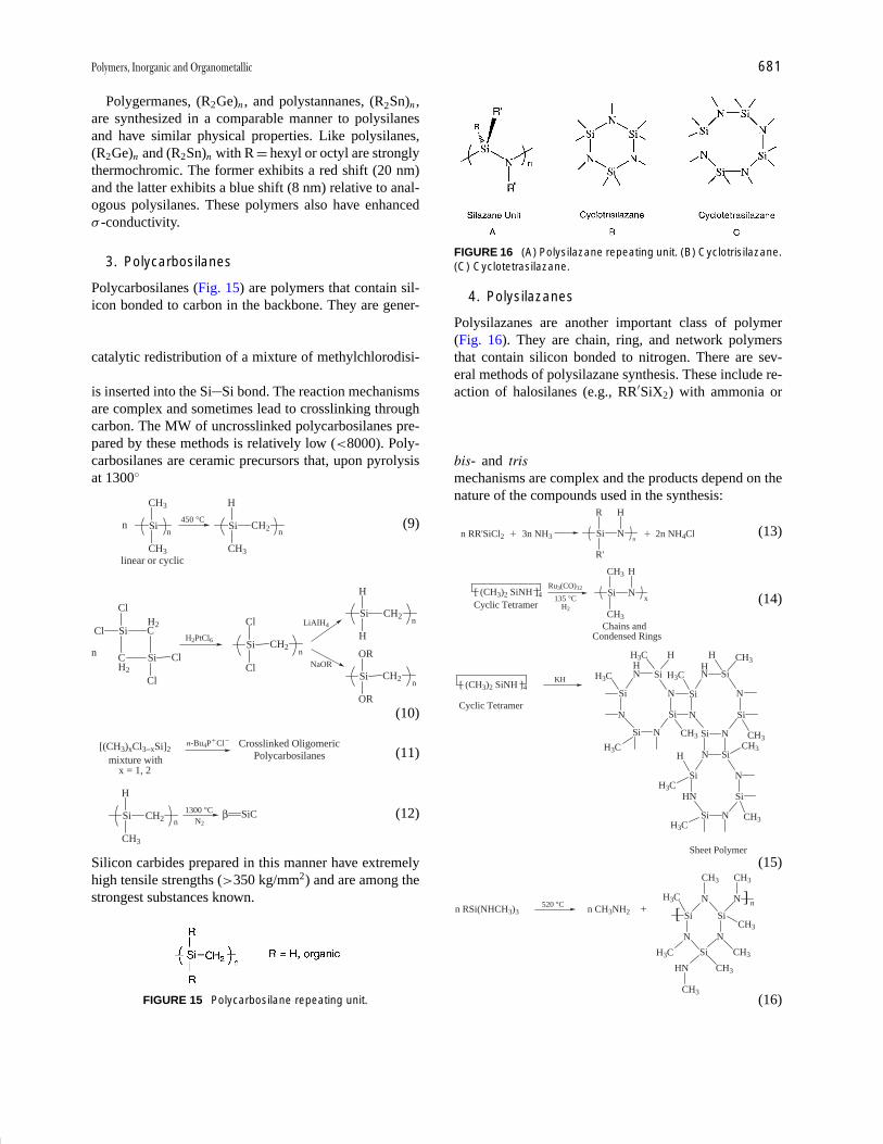
P1: GKY/MBQ P2: GLQ Final Pages
Encyclopedia of Physical Science and Technology en012i-947 July 26, 2001 11:11
Polymers, Inorganic and Organometallic 681
Polygermanes, (R2Ge)n , and polystannanes, (R2Sn)n ,are synthesized in a comparable manner to polysilanesand have similar physical properties. Like polysilanes,(R2Ge)n and (R2Sn)n with R = hexyl or octyl are stronglythermochromic. The former exhibits a red shift (20 nm)and the latter exhibits a blue shift (8 nm) relative to anal-ogous polysilanes. These polymers also have enhancedσ -conductivity.
3. Polycarbosilanes
Polycarbosilanes (Fig. 15) are polymers that contain sil-icon bonded to carbon in the backbone. They are gener-ally prepared by thermolysis of polysilanes [Eq. (9)], cat-alytic ring-opening of cyclic carbosilanes [Eq. (10)], orcatalytic redistribution of a mixture of methylchlorodisi-lanes [Eq. (11)]. In these reactions the methylene groupis inserted into the Si Si bond. The reaction mechanismsare complex and sometimes lead to crosslinking throughcarbon. The MW of uncrosslinked polycarbosilanes pre-pared by these methods is relatively low (<8000). Poly-carbosilanes are ceramic precursors that, upon pyrolysisat 1300◦C, give silicon carbide [Eq. (12)]:
Si
CH3
CH3
n
450 °CSi
H
CH3
CH2 n
linear or cyclic
n (9)
Cl Si
Cl
C
C
Si
Cl
Cl
H2
H2
H2PtCl6 Si
Cl
Cl
CH2n n
LiAIH4
NaOR
Si
H
H
CH2 n
Si
OR
OR
CH2 n
(10)
[(CH3)xCl3−xSi]2n-Bu4P�Cl� Crosslinked Oligomeric
Polycarbosilanes
x = 1, 2mixture with
(11)
Si
H
CH3
CH21300 °C
N2β
nSiC (12)
Silicon carbides prepared in this manner have extremelyhigh tensile strengths (>350 kg/mm2) and are among thestrongest substances known.
FIGURE 15 Polycarbosilane repeating unit.
FIGURE 16 (A) Polysilazane repeating unit. (B) Cyclotrisilazane.(C) Cyclotetrasilazane.
4. Polysilazanes
Polysilazanes are another important class of polymer(Fig. 16). They are chain, ring, and network polymersthat contain silicon bonded to nitrogen. There are sev-eral methods of polysilazane synthesis. These include re-action of halosilanes (e.g., RR′SiX2) with ammonia oramines [Eq. (13)], ring-opening polymerization of cy-closilazane [Eq. (14)], catalytic dehyrocoupling polymer-ization [Eq. (15)], and deamination and condensation ofbis- and tris-alkyaminosilanes [Eq. (16)]. The reactionmechanisms are complex and the products depend on thenature of the compounds used in the synthesis:
n RR'SiCl2 � 3n NH3 Si
R
R'
Nn
H
� 2n NH4Cl (13)
[ (CH3)2 SiNH ]4
Cyclic Tetramer135 °C
H2
Ru3(CO)12Si
CH3
CH3
Nx
H
Chains andCondensed Rings
(14)
[ (CH3)2 SiNH ]4
Cyclic Tetramer
KH
Si
N
Si N
Si
N
SiNH3C
H3C
H3C
HH
Si
N
Si N
Si
N
SiNH3C
H CH3H
CH3CH3
Si
HN
Si N
Si
N
SiNCH3
CH3
H
H3C
H3C
Sheet Polymer(15)
n RSi(NHCH3)3520 °C n CH3NH2 +
Si
N
Si
N
Si
N
CH3
H3C
H3C
N
CH3
HN
CH3
CH3
CH3
CH3
][
n
(16)

P1: GKY/MBQ P2: GLQ Final Pages
Encyclopedia of Physical Science and Technology en012i-947 July 26, 2001 11:11
682 Polymers, Inorganic and Organometallic
For example, if R = R′ = H in ring-opening polymeriza-tion, only chain oligomers of relatively low MW (∼1000)are obtained. If R = CH3 and R′ = H, the products are amixture of cyclic and chain oligomers. If R is larger thanmethyl, only cyclotri- and cyclotetrasilazanes are formed(Fig. 16B, C). Products with higher degrees of polymer-ization are obtained by dehydrocoupling of the oligomers.
The primary use of polysilazanes is as prepolymersin the manufacture of silicon nitride ceramics. Thus,heating (<1000◦C) the oligomers results in progressivedeamination–condensation to give a cyclomatrix polymer.Ceramic silicon nitride is formed upon further heating(>1000◦C) under vacuum. The high tensile strength cou-pled with thermal and oxidative stability of silicon nitridesmakes them useful as tough ceramic coatings or high-impact composites in heat engine parts, power-generatingturbines, and machine bearings. They are also used as re-fractory materials for heat- and corrosion-resistant jigs andin devices where high-temperature insulation is required.
B. Phosphorus-Based Polymers
1. Polyphosphazenes
Polyphosphazenes are polymers that contain alternatingphosphorus and nitrogen atoms. Two organic, inorganic,or organometallic substituents are bonded to phosphorus(Fig. 17). An important feature of polyphosphazenes istheir synthetic methodology that provides an enormousvariety in the types of R groups attached to the P. As a re-sult, a large number of polyphosphazenes have been syn-thesized and characterized (Fig. 18). The diverse chemi-cal and physical properties of these polymers make themimportant candidates for many industrial and consumerapplications. Some applications associated with differentsubstituents on the PN chain are summarized in Table III.
There are several methods of polyphosphazene syn-thesis: ring-opening polymerization (ROP), condensationpolymerization (CP), and more recently anionic polymer-ization (AP). In the case of ROP, the primary commercialstarting material is highly purified hexachlorocyclot-riphosphazene, [NPCl2]3. The cyclic trimer, which is
FIGURE 17 Polyphosphazene repeating unit.
FIGURE 18 Synthesis of substituted polyphosphazenes.
prepared from PCl5 and NH3 (or NH4Cl), is then carefullyheated above 200◦C to induce polymerization [Eqs. (17),(18)]:
3 PCl5 � 3 NH3N N
P
PN
PCl
Cl
Cl
Cl
� 9 HCl
ClCl
(17)
N N
P
PN
PCl
Cl
Cl
Cl
n210 - 250 �C
N P3n
Cl
Cl
ClCl
(18)
The product is a linear polymer that is soluble in organicsolvents. The degree of polymerization using this method
TABLE III Applications of Polyphosphazenes with VariousSubstituents
Substituents Applications
OCH2(CF2)x CF3 Hydrocarbon-resistant O-rings,gaskets, coatings, and fuel linesand nonflammable polymers
OC6H5 Electrical, heat, and sound insulationmaterials, immobilized enzymes
OC2H4OC2H4OCH3 Polymer electrolytes in batteries,hydrogels for soft tissue medicalapplications
O[Si(CH3)2]nOSi(CH3)3 Hydrophobic polymers
NHC2H5 Hydrophilic polymers
NHCH2COOC2H5 Bioerodible polymers
O-Steroid Drug delivery polymers
O-Procaine Local anesthetic
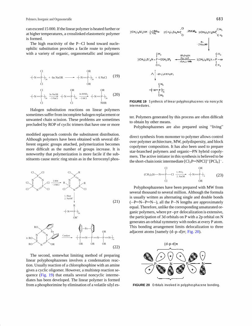
P1: GKY/MBQ P2: GLQ Final Pages
Encyclopedia of Physical Science and Technology en012i-947 July 26, 2001 11:11
Polymers, Inorganic and Organometallic 683
can exceed 15 000. If the linear polymer is heated further orat higher temperatures, a crosslinked elastomeric polymeris formed.
The high reactivity of the P Cl bond toward nucle-ophilic substitution provides a facile route to polymerswith a variety of organic, organometallic and inorganicsubstituents. For example, homopolymers [Eq. (19)] andcopolymers [Eq. (20)] are available through this route:
N P3n
Cl
Cl
� 6n NaOR N P3n
OR
OR
� 6 NaCl (19)
N P3n
Cl
Cl
3n NaOR
�3 NaClN P
3n
OR
Cl
3n RNH2
�3 HClN P
3n
OR
NHR
(20)
Halogen substitution reactions on linear polymerssometimes suffer from incomplete halogen replacement orunwanted chain scission. These problems are sometimesprecluded by ROP of cyclic trimers that have one or moreof the halogens replaced with R groups [Eq. (21)]. Thismodified approach controls the substitutent distribution.Although polymers have been obtained with several dif-ferent organic groups attached, polymerization becomesmore difficult as the number of groups increase. It isnoteworthy that polymerization is more facile if the sub-stituents cause steric ring strain as in the ferrocenyl phos-phazene trimer [Eq. (22)]:
N N
P
PN
PCl
Cl
Cl
Cl
N P3n
R
OR′
�3 MCl
3 RM N N
P
PN
PR
Cl
R
Cl
Cl R
1. Heat2. NaOR′
Cl Cl
(21)
N N
P
PN
PRO
RO OR
nCatalyst
P Nn
OR
RO
Fe
P N
OR
P N
OR
ORFe
(22)
The second, somewhat limiting method of preparinglinear polyphosphazenes involves a condensation reac-tion. Usually reaction of a chlorophosphine with an aminegives a cyclic oligomer. However, a multistep reaction se-quence (Fig. 19) that entails several noncyclic interme-diates has been developed. The linear polymer is formedfrom a phosphorimine by elimination of a volatile silyl es-
FIGURE 19 Synthesis of linear polyphosphazenes via noncyclicintermediates.
ter. Polymers generated by this process are often difficultto obtain by other means.
Polyphosphazenes are also prepared using “living”cationic catalysts at room temperature [Eq. (23)]. Thisdirect synthesis from monomer to polymer allows controlover polymer architecture, MW, polydispersity, and blockcopolymer composition. It has also been used to preparestar-branched polymers and organic PN hybrid copoly-mers. The active initiator in this synthesis is believed to bethe short-chain ionic intermediate [Cl3P NPCl]+[PCl6]−.
N Pn
OR
OR
2. NaOR
1. PCl5N P
Cl
Cl
Cl(CH3)3Si (23)
Polyphosphazenes have been prepared with MW fromseveral thousand to several million. Although the formulais usually written as alternating single and double bonds( P N P N ), all the P N lengths are approximatelyequal. Therefore, unlike the corresponding unsaturated or-ganic polymers, where pπ–pπ delocalization is extensive,the participation of 3d orbitals on P with a 2p orbital on Ngenerates an orbital symmetry with nodes at every P atom.This bonding arrangement limits delocalization to threeadjacent atoms [namely (d–p–d)π; Fig. 20).
FIGURE 20 Orbitals involved in polyphosphazene bonding.

P1: GKY/MBQ P2: GLQ Final Pages
Encyclopedia of Physical Science and Technology en012i-947 July 26, 2001 11:11
684 Polymers, Inorganic and Organometallic
The ability to alter pendant substituents and controlMW, polydispersity, solubility, polymer architecture, andcopolymer composition gives versatility to polyphosp-hazenes. The polymers can vary from elastomers to ce-ramics, from hydrophobic to hydrophilic, from bioactiveto bioinert, and from electrical conductor to insulator. Inaddition, many of these polymers have low Tg values (e.g.,Tg([Cl2PN]n) = −63◦C) that result in rubbery behavior atfairly low temperatures.
2. Poly(carbophosphazene)and Poly(thiophosphazene)
The backbone of the polyphosphazene chain can bemodified by insertion of heteroatoms such as car-bon [poly(carbophosphazene)] or sulfur [poly(thio-phosphazene)]. These polymers are obtained by heatingthe heterocyclic trimer analogs that are prepared by a3 + 3 cocondensation reaction as illustrated in Fig. 21.Unless the poly(thiophosphazene) has bulky sidegroups, itis hydrolytically unstable. However, if the oxidation stateof sulfur is increased to VI [poly(thionylphosphazene),Fig. 22], the polymer is stable to atmospheric moisture.Moreover, only the halogens on P undergo substitutionwith NaOR (R = phenyl).
An interesting feature of these polymers is the increasein Tg relative to [R2PN]n . This suggests that the presenceof carbon or sulfur significantly reduces chain mobilityand flexibility presumably because of the higher rotationalbarrier in C N and S N and the increase in intermolecu-
FIGURE 21 Synthesis of poly(carbophosphazene) and poly(thiophosphazene).
lar interactions in the more polar C O or S O bonds. TheMW of the thionyl polymers, determined from light scat-tering, range from 5000 to 140 000 with polydispersitiesfrom 1.4 to 2.3 depending on the substituents. The combi-nation of low Tg and high oxygen diffusion coefficient forsome of these polymers has led to applications as matri-ces for pressure and phosphorescence sensor compositesin the aerospace industry.
3. Other Phosphorus-Containing Polymers
Oligomers and polymers of elemental phosphorus werementioned previously (Section II). Although they arerather sensitive toward atmospheric oxygen and moisture,in small quantities they have applications as fire retar-dants, surface treatment of metals for coatings, and in ion-exchange resins. Oligomers and polymers of phosphoruswith oxygen [P4O6, P4O10, P8O16, (PO)n, P3O5−
8 , P6O6−12
and (PO3)n−n ] are well known. Several examples are given
in Fig. 23. The small neutral P O and P S compoundshave polyhedral cage structures. (PO3)n−
n polymers, how-ever, are composed of orthophosphate (phosphoanhy-dride) residues in which n may be several multiples of10 to several hundred. These macromolecules are con-stituent parts of all living cells and are responsible forcellular energy transfer and other biochemical processes.Phosphorus–sulfur oligomers (P4Sx , x = 3, 5, 7, 9, 10)are also known.
Aromatic polyphosphates that are prepared from phos-phodichloridates and aromatic diols [Eq. (24)] possess the

P1: GKY/MBQ P2: GLQ Final Pages
Encyclopedia of Physical Science and Technology en012i-947 July 26, 2001 11:11
Polymers, Inorganic and Organometallic 685
FIGURE 22 Synthesis of poly(thionylphosphazene).
useful properties of hardness, high transparency and flameretardancy:
n RO PCl2
O
n HO OH��2n HCl
O OP
O
OR
n
(24)
However, these materials lack long-term hydrolytic sta-bility. The hydrolysis problem has been partially over-come by elimination of the P O linkage as in thepoly(phosphinoisocyanate)s [Eq. (25)]:
n RPH2 � CP
O
nn OCN R′ NCO
R
N R′
H
N
H
(25)
If metal alkoxides (e.g. MOR, M = Al, Co, Cr, etc.) reactwith a diorganophosphinic acid [R2PO(OH)], poly(metalphosphinate)s with general formula [M(OPR2O)2]n areformed.
Poly(phosphoryldimethylamide)s are obtained froma complex reaction of P4O10, [(CH3)2N]3P O, andCl3P O (Fig. 24). This class of polymer has elastomericproperties.
FIGURE 23 Phosphorus–oxygen oligomers and polymer(polyphosphate)
C. Boron-Based Polymers
1. Boron–Hydrogen Polymers: Polyboranes
Polymers that contain boron may be classified into twocategories: homoatom polymers that are anionic (seeTable I) or neutral and heteroatom polymers that con-tain boron with carbon, oxygen, nitrogen, phosphorous, orother elements. The latter may be neutral or ionic. Some ofthe homoatom anionic polymers (borides) were mentionedearlier (Section II). A simple homoatom polymer of boronis [BF]n , which presumably contains BF repeating unitswith B B bonds in the backbone. [BF]n is prepared fromelemental boron and BF3 at high temperature. The poly-mer is an elastomer. However, owing to its pyrophoricityand sensitivity to moisture, it has not been fully charac-terized. Boron oligomers that contain B H (polyboranes)are interesting because of their “nonclassical,” multicen-ter covalent bonds (Fig. 25) and their unusual weblike(arachno), nestlike (nido), and cagelike (closo) structures(Fig. 26).
The structures of some neutral polyboranes with for-mulas BnHn+4 (n = 5, 6, 10, 16, 18) and BnHn+6 (n = 4,
5, 10) and several anionic polyboranes (B6H2−6 , B12H2−
12 ,and B18H2−
20 ) are given in Fig. 26. Although these unusualcluster oligomers have fascinating structures and remark-able bonding, the difficulties encountered in large-scale
FIGURE 24 Poly(phosphoryldimethylamide) repeating unit.
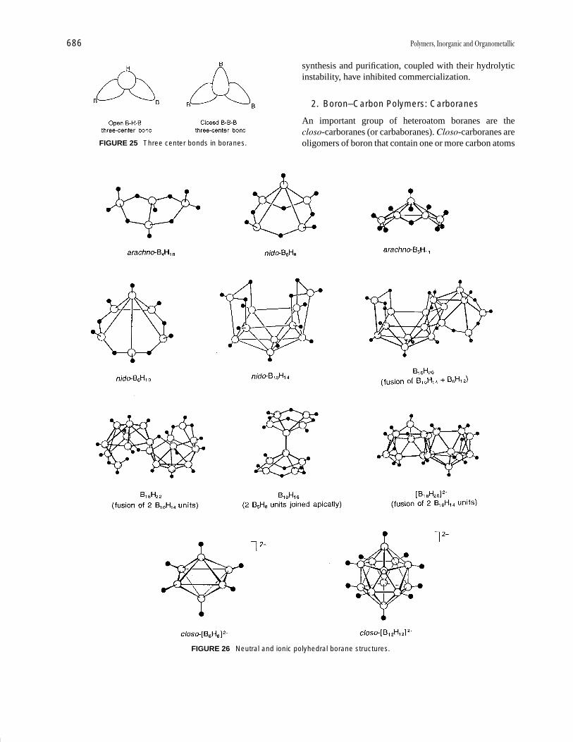
P1: GKY/MBQ P2: GLQ Final Pages
Encyclopedia of Physical Science and Technology en012i-947 July 26, 2001 11:11
686 Polymers, Inorganic and Organometallic
FIGURE 25 Three center bonds in boranes.
FIGURE 26 Neutral and ionic polyhedral borane structures.
synthesis and purification, coupled with their hydrolyticinstability, have inhibited commercialization.
2. Boron–Carbon Polymers: Carboranes
An important group of heteroatom boranes are thecloso-carboranes (or carbaboranes). Closo-carboranes areoligomers of boron that contain one or more carbon atoms

P1: GKY/MBQ P2: GLQ Final Pages
Encyclopedia of Physical Science and Technology en012i-947 July 26, 2001 11:11
Polymers, Inorganic and Organometallic 687
FIGURE 27 Synthesis of closo-dodecacarboranes.
in the polyhedral cage structure. These oligomers are gen-erally unaffected by atmospheric oxygen and moisture.Some of the materials are thermally stable to 500◦C. Aparticularly important group of carboranes are the deriva-tives of closo-dodecaborane. These compounds are pre-pared from nido-decaborane and acetylene in the pres-ence of ethyl sulfide (Fig. 27). The primary product ofthe reaction is closo-1,2-C2B10H12 (ortho isomer). Theortho isomer undergoes rearrangement at 450◦C to closo-1,7-C2B10H12 (meta isomer), and at 700◦C to closo-1,12-C2B10H12 (para isomer). The H atoms attached tothe electropositive carbons, like acetylene, are acidic. Thusthe C H bonds may be metallated with reagents like n-BuLi. The lithiated derivative reacts with nucleophiles toproduce a wide variety of organometallic products. Forexample, the reaction of the meta isomer with a dichloroend-functional oligomeric siloxane will give a carborane–siloxane copolymer (Fig. 28). Some of these materials arecommercially available (Dexil®) as rubbers and resins.They preserve their elasticity and mechanical propertiesat low temperatures, and are thermally stable to 600◦C.
3. Boron–Nitrogen and Boron–Oxygen Polymers
Nonoxide, solid-state ceramics of boron and nitrogen(boron nitrides) are of commercial interest owing totheir chemical inertness and robust physical, mechanical,
and thermal properties. BN materials have applicationsas ceramic coatings, fiber-reinforced plastics, and bulkcomposites. Boron nitride may be obtained from simplereagents such as elemental B and N2 or B2O3 and NH3,using high-energy reaction conditions (Fig. 29). Boron ni-tride prepared in this manner has a hexagonal crystallineform (α form) of planar sheets with six-member fusedrings containing alternating B–N bonds. The structure issimilar to graphite except (1) the layers are directly aligned(as opposed to offset) with the B on one sheet directlyover the N on the neighboring sheet and (2) the sheets arecloser together (1.45 A vs. 3.35 A in graphite). There arealso salient differences in some of the physical propertiesof α-BN. For example, α-BN is colorless and an electri-cal insulator, whereas graphite is black and an electricalconductor. However, the lamella layers in both α-BN andgraphite easily slip past one another, giving rise to theirlubricity.
α-BN undergoes structural reorientation to the moredense β-BN (cubic) form when heated under pressure.The boron atoms in the cubic form occupy tetrahedralsites in the crystal lattice analogous to carbon in diamond.Thus β-BN is extremely hard, second only to diamond,and is used industrially as a high-temperature abrasive.
Alternate synthetic routes to boron nitrides through BN-containing oligomers and preceramic polymers have beendeveloped. For example, pyrolysis of poly(borazylene),
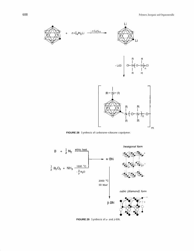
P1: GKY/MBQ P2: GLQ Final Pages
Encyclopedia of Physical Science and Technology en012i-947 July 26, 2001 11:11
688 Polymers, Inorganic and Organometallic
FIGURE 28 Synthesis of carborane–siloxane copolymer.
FIGURE 29 Synthesis of α- and β-BN.
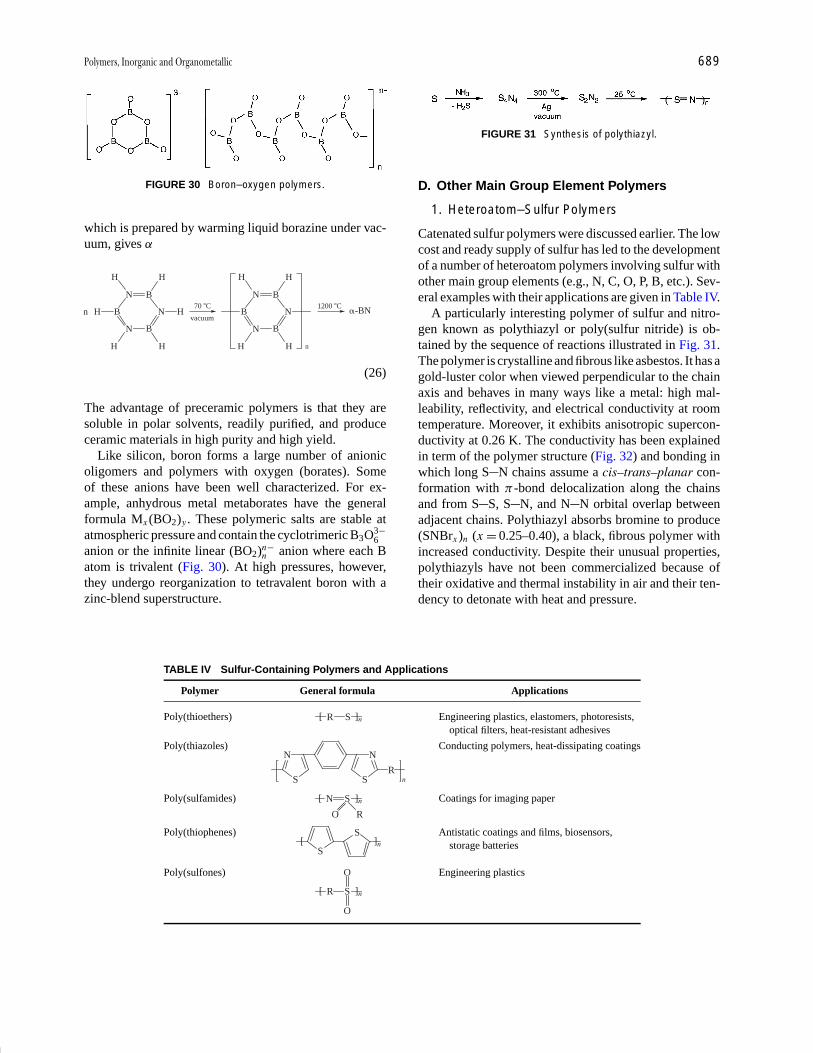
P1: GKY/MBQ P2: GLQ Final Pages
Encyclopedia of Physical Science and Technology en012i-947 July 26, 2001 11:11
Polymers, Inorganic and Organometallic 689
FIGURE 30 Boron–oxygen polymers.
which is prepared by warming liquid borazine under vac-uum, gives α-BN [Eq. (26)]:
N B
B
N B
NH Hnvacuum
70 �C
H H
HH
N B
B
N B
N
H H
HH n
1200 �C�-BN
(26)
The advantage of preceramic polymers is that they aresoluble in polar solvents, readily purified, and produceceramic materials in high purity and high yield.
Like silicon, boron forms a large number of anionicoligomers and polymers with oxygen (borates). Someof these anions have been well characterized. For ex-ample, anhydrous metal metaborates have the generalformula Mx (BO2)y . These polymeric salts are stable atatmospheric pressure and contain the cyclotrimeric B3O3−
6anion or the infinite linear (BO2)n−
n anion where each Batom is trivalent (Fig. 30). At high pressures, however,they undergo reorganization to tetravalent boron with azinc-blend superstructure.
TABLE IV Sulfur-Containing Polymers and Applications
Polymer General formula Applications
Poly(thioethers) Engineering plastics, elastomers, photoresists,optical filters, heat-resistant adhesives
R S[ ]n
Poly(thiazoles) Conducting polymers, heat-dissipating coatings
S
N
S
N
Rn
Poly(sulfamides) Coatings for imaging paperN S
O R
[ ]n
Poly(thiophenes) Antistatic coatings and films, biosensors,storage batteriesS
Sn[ ]
Poly(sulfones) Engineering plastics
R S
O
[ ]n
O
FIGURE 31 Synthesis of polythiazyl.
D. Other Main Group Element Polymers
1. Heteroatom–Sulfur Polymers
Catenated sulfur polymers were discussed earlier. The lowcost and ready supply of sulfur has led to the developmentof a number of heteroatom polymers involving sulfur withother main group elements (e.g., N, C, O, P, B, etc.). Sev-eral examples with their applications are given in Table IV.
A particularly interesting polymer of sulfur and nitro-gen known as polythiazyl or poly(sulfur nitride) is ob-tained by the sequence of reactions illustrated in Fig. 31.The polymer is crystalline and fibrous like asbestos. It has agold-luster color when viewed perpendicular to the chainaxis and behaves in many ways like a metal: high mal-leability, reflectivity, and electrical conductivity at roomtemperature. Moreover, it exhibits anisotropic supercon-ductivity at 0.26 K. The conductivity has been explainedin term of the polymer structure (Fig. 32) and bonding inwhich long S N chains assume a cis–trans–planar con-formation with π -bond delocalization along the chainsand from S S, S N, and N N orbital overlap betweenadjacent chains. Polythiazyl absorbs bromine to produce(SNBrx )n (x = 0.25–0.40), a black, fibrous polymer withincreased conductivity. Despite their unusual properties,polythiazyls have not been commercialized because oftheir oxidative and thermal instability in air and their ten-dency to detonate with heat and pressure.

P1: GKY/MBQ P2: GLQ Final Pages
Encyclopedia of Physical Science and Technology en012i-947 July 26, 2001 11:11
690 Polymers, Inorganic and Organometallic
FIGURE 32 Structure of polythiazyl.
2. Aluminum-Containing Polymers
Aluminum forms heteroatom oligomers and polymersmainly with oxygen and nitrogen. The Al O polymersare formed by (1) hydrolysis of multifunctional alanes(RnAlX3−n , n = 0, 1; R = organic; X = Cl, OR) to givepoly(organoaloxane)s [Eq. (27)] or (2) the reaction oftrialkyl- or trialkoxyalanes with organic acids to givepoly(acyloxyaloxane)s (Fig. 33A, B):
n RAlCl3 � n H2O Al O
R
( ) n � 2n H2O (27)
In the latter reaction, an excess of carboxylic acid orchelating reagent such as acetylacetone (Fig. 33C), diol,or aminoalcohol produces a more soluble, higher MW,and processible material. The bulk of the evidence sug-gests that the products are highly crosslinked networkstructures. These preceramic polymers are used to pre-pare high-performance alumina (Al2O3) fibers. Generally,Al O polymers range from gums to brittle solids. In addi-
FIGURE 33 Al O polymer repeating units.
tion to ceramic fibers, they have applications as lubricants,fuel additives, catalysts, gelling and drying agents, waterrepellants, and additives to paints and varnishes. If oxygenin the backbone is replaced with NH or NR, the polymersare thermally unstable and sensitive to acids, bases, andwater.
A variety of Al O Si O polymers, poly(alumino-siloxanes), with Si:Al ratios from 0.8 to 23, are known.These materials are prepared by the reaction of sodiumoligo(organosiloxanate)s with AlCl3 [Eq. (28)]:
Na��O Si
R
R
( O Si )n O Si Na� �AICI3O�
R
R
R
R
�NaCIAl O Si ( O Si )n O Si O
R
R
R
R
Al
O
O
R
R
(28)

P1: GKY/MBQ P2: GLQ Final Pages
Encyclopedia of Physical Science and Technology en012i-947 July 26, 2001 11:11
Polymers, Inorganic and Organometallic 691
FIGURE 34 Poly(aluminosiloxane) ladder polymer.
If a trifunctional silane is used, the Si:Al ratio is largerthan 7 and a soluble polymer, believed to have a ladderstructure, is obtained (Fig. 34).
The aluminosilicates are anionic polymers that arepresent in natural and synthetic minerals where Al(III)
FIGURE 35 Heteroatom tin-containing polymers.
ions replace Si(IV) in the lattice. Examples of 2D sheetaluminosilicates are clays, micas, and talc. Feldspar andzeolites (molecular sieves) are 3D network structures inwhich AlO4 and SiO4 units share tetrahedral vertices. Thecavities created in these network polymers are accommo-dated by cations such as Na+ and K+. Depending on thesize of the cavity, these cations can be displaced by othercations, hence their use as ion exchange materials. More-over, by synthetically controlling the size and shape ofthe cavity, small molecules like water, methanol, or gasescan be selectively trapped. Thus these materials are usedin laboratory and industrial separations and purificationprocesses (Table V).
3. Tin-Containing Polymers
Polystannanes as analogs to polysilanes were mentionedearlier. There are also a number of heteroatom polymers of
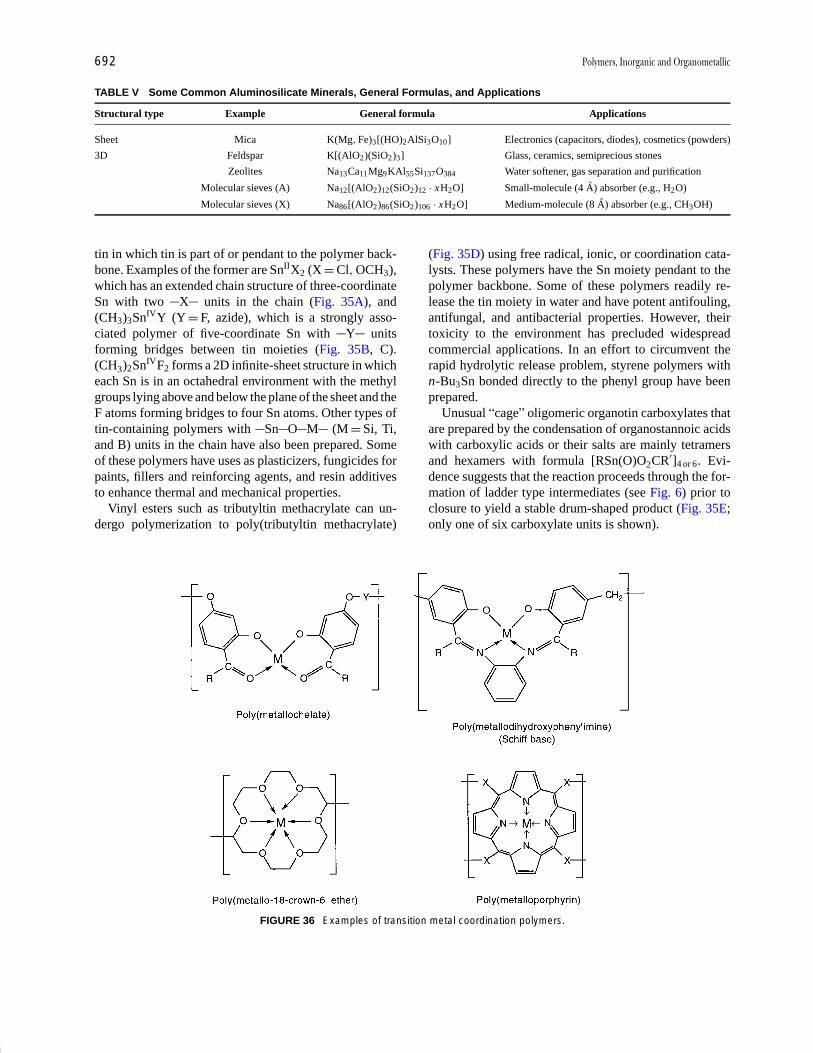
P1: GKY/MBQ P2: GLQ Final Pages
Encyclopedia of Physical Science and Technology en012i-947 July 26, 2001 11:11
692 Polymers, Inorganic and Organometallic
TABLE V Some Common Aluminosilicate Minerals, General Formulas, and Applications
Structural type Example General formula Applications
Sheet Mica K(Mg, Fe)3[(HO)2AlSi3O10] Electronics (capacitors, diodes), cosmetics (powders)
3D Feldspar K[(AlO2)(SiO2)3] Glass, ceramics, semiprecious stones
Zeolites Na13Ca11Mg9KAl55Si137O384 Water softener, gas separation and purification
Molecular sieves (A) Na12[(AlO2)12(SiO2)12 · xH2O] Small-molecule (4 A) absorber (e.g., H2O)
Molecular sieves (X) Na86[(AlO2)86(SiO2)106 · xH2O] Medium-molecule (8 A) absorber (e.g., CH3OH)
tin in which tin is part of or pendant to the polymer back-bone. Examples of the former are SnIIX2 (X = Cl, OCH3),which has an extended chain structure of three-coordinateSn with two X units in the chain (Fig. 35A), and(CH3)3SnIVY (Y = F, azide), which is a strongly asso-ciated polymer of five-coordinate Sn with Y unitsforming bridges between tin moieties (Fig. 35B, C).(CH3)2SnIVF2 forms a 2D infinite-sheet structure in whicheach Sn is in an octahedral environment with the methylgroups lying above and below the plane of the sheet and theF atoms forming bridges to four Sn atoms. Other types oftin-containing polymers with Sn O M (M = Si, Ti,and B) units in the chain have also been prepared. Someof these polymers have uses as plasticizers, fungicides forpaints, fillers and reinforcing agents, and resin additivesto enhance thermal and mechanical properties.
Vinyl esters such as tributyltin methacrylate can un-dergo polymerization to poly(tributyltin methacrylate)
FIGURE 36 Examples of transition metal coordination polymers.
(Fig. 35D) using free radical, ionic, or coordination cata-lysts. These polymers have the Sn moiety pendant to thepolymer backbone. Some of these polymers readily re-lease the tin moiety in water and have potent antifouling,antifungal, and antibacterial properties. However, theirtoxicity to the environment has precluded widespreadcommercial applications. In an effort to circumvent therapid hydrolytic release problem, styrene polymers withn-Bu3Sn bonded directly to the phenyl group have beenprepared.
Unusual “cage” oligomeric organotin carboxylates thatare prepared by the condensation of organostannoic acidswith carboxylic acids or their salts are mainly tetramersand hexamers with formula [RSn(O)O2CR′]4 or 6. Evi-dence suggests that the reaction proceeds through the for-mation of ladder type intermediates (see Fig. 6) prior toclosure to yield a stable drum-shaped product (Fig. 35E;only one of six carboxylate units is shown).

P1: GKY/MBQ P2: GLQ Final Pages
Encyclopedia of Physical Science and Technology en012i-947 July 26, 2001 11:11
Polymers, Inorganic and Organometallic 693
FIGURE 37 Metallophthalocyanine (shish kebab) polymers.
IV. INORGANIC POLYMERSWITH TRANSITION METALS
A. Transition Metal Coordination Polymers
There are numerous examples of inorganic polymers withtransition elements. These polymers have the metal asan integral part of or pendant to the polymer backbone.Generally the metal is attached to a ligand (L) by oneor more σ -coordinate covalent bonds (M ← L) throughheteroatoms such as O, N, P, or S on L. The polymerarises by connecting metal units through the ligands.Examples of coordinating ligands are polydentate chelat-ing compounds such as porphyrins, phthalocyanines,phosphinates, β-diketones, dioximes, Schiff bases, andcrown ethers. Several coordination polymers with differ-ent ligands are shown in Fig. 36.
Two interesting cases are worth noting:
1. The poly(metallophthalocyanine) (shish kebab)polymers in which M = Si, Ge, Sn, or Ni. These poly-mers are made up of planar phthalocyanine units withthe N atoms tetracoordinated to M. The macrocyclesare stacked one dimensionally through metalloxy bonds(Fig. 37). The materials are prepared by dehydration
FIGURE 38 Zinc-porphyrin (photonic wire) polymer.
of the metallophthalocyanine dihydroxide. Similar poly-mers with S, Se, and Te as bridging atoms are knownand are soluble in strong acids. Moreover, they have fa-vorable dynamic–mechanical properties comparable topolyamides (e.g., Kevlar®). If doped with iodine, shishkebab polymers exhibit potentially useful magnetic, elec-tronic and optical behavior.
2. The molecular photonic wire composed of a zinc–porphyrin chain with a boron dipyrromethane group at oneend and a free base prophyrin at the other end (Fig. 38).This oligomer is photochromic and absorbs blue-greenlight at boron and emits red light at the uncomplexed site.Such macromolecules have potential as molecular wiresin molecular devices.
A general method of preparing coordination polymersinvolves the reaction of the free metal, metal salt, ormetal complex with a polydentate ligand. For example,the reaction of nickel acetate with bis(1,2-dioxime) givesa polymer with tetracoordination of the ligand nitrogenatoms with nickel (Eq. 29). Metal-containing polymerswith two or more different atoms of the ligand bonded tothe metal are also possible (Eq. 30).
CH3C C R C CCH3
HON NOH HON NOH� Ni(O2CCH3)2
�CH3CO2H
NO
H Ni
NO
N O
H
N O
CH3C C
C CCH3R
(29)
:N N:
HO OH
:N N:
O O
M� MX2�2HX
(30)
To date, owing to their low solubility, aggregation togive intractable solids, and difficulty in processing, thereare relatively few commercial applications for coordina-tion polymers. Some materials have found promise as non-linear optical materials, electrical conductors, photosensi-tive coatings and films, and bioactive releasing agents. For
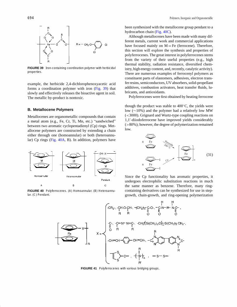
P1: GKY/MBQ P2: GLQ Final Pages
Encyclopedia of Physical Science and Technology en012i-947 July 26, 2001 11:11
694 Polymers, Inorganic and Organometallic
FIGURE 39 Iron-containing coordination polymer with herbicidalproperties.
example, the herbicide 2,4-dichlorophenoxyacetic acidforms a coordination polymer with iron (Fig. 39) thatslowly and effectively releases the bioactive agent in soil.The metallic by-product is nontoxic.
B. Metallocene Polymers
Metallocenes are organometallic compounds that containa metal atom (e.g., Fe, Cr, Ti, Mn, etc.) “sandwiched”between two aromatic cyclopentadienyl (Cp) rings. Met-allocene polymers are constructed by extending a chaineither through one (homoannular) or both (heteroannu-lar) Cp rings (Fig. 40A, B). In addition, polymers have
FIGURE 40 Polyferrocenes. (A) Homoannular. (B) Heteroannu-lar. (C) Pendant.
FIGURE 41 Polyferrocenes with various bridging groups.
been synthesized with the metallocene group pendant to ahydrocarbon chain (Fig. 40C).
Although metallocenes have been made with many dif-ferent metals, current work and commercial applicationshave focused mainly on M = Fe (ferrocene). Therefore,this section will explore the synthesis and properties ofpolyferrocenes. The great interest in polyferrocenes stemsfrom the variety of their useful properties (e.g., highthermal stability, radiation resistance, diversified chem-istry, high energy content, and, recently, catalytic activity).There are numerous examples of ferrocenyl polymers asconstituent parts of elastomers, adhesives, electron trans-fer resins, semiconductors, UV absorbers, solid-propellantadditives, combustion activators, heat transfer fluids, lu-bricants, and antioxidants.
Polyferrocenes were first obtained by heating ferrocenein the presence of a free radical catalyst [Eq. (31)]. Al-though the product was stable to 400◦C, the yields werelow (∼10%) and the polymer had a relatively low MW(<3000). Grignard and Wurtz-type coupling reactions on1,1′-diiodoferrocene have improved yields considerably(>80%); however, the degree of polymerization remainedlow.
Fen
Fen
Fe
nI
I
Peroxide200 �C
Cu
(31)
Since the Cp functionality has aromatic properties, itundergoes electrophilic substitution reactions in muchthe same manner as benzene. Therefore, many ring-containing derivatives can be synthesized for use in step-growth, chain-growth, and ring-opening polymerization
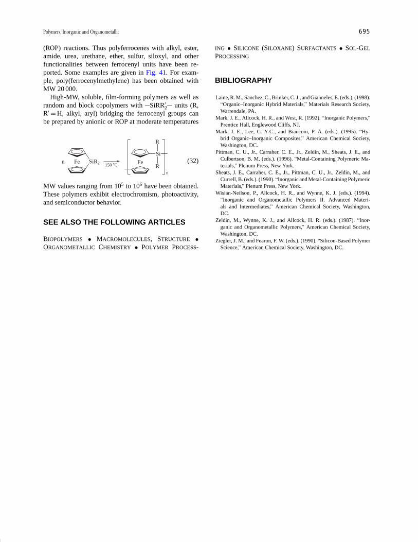
P1: GKY/MBQ P2: GLQ Final Pages
Encyclopedia of Physical Science and Technology en012i-947 July 26, 2001 11:11
Polymers, Inorganic and Organometallic 695
(ROP) reactions. Thus polyferrocenes with alkyl, ester,amide, urea, urethane, ether, sulfur, siloxyl, and otherfunctionalities between ferrocenyl units have been re-ported. Some examples are given in Fig. 41. For exam-ple, poly(ferrocenylmethylene) has been obtained withMW 20 000.
High-MW, soluble, film-forming polymers as well asrandom and block copolymers with SiRR′
2 units (R,R′ = H, alkyl, aryl) bridging the ferrocenyl groups canbe prepared by anionic or ROP at moderate temperatures[Eq. (32)]:
Fen Fe
Si
n
150 �C
R
RSiR2 (32)
MW values ranging from 105 to 106 have been obtained.These polymers exhibit electrochromism, photoactivity,and semiconductor behavior.
SEE ALSO THE FOLLOWING ARTICLES
BIOPOLYMERS • MACROMOLECULES, STRUCTURE •ORGANOMETALLIC CHEMISTRY • POLYMER PROCESS-
ING • SILICONE (SILOXANE) SURFACTANTS • SOL-GEL
PROCESSING
BIBLIOGRAPHY
Laine, R. M., Sanchez, C., Brinker, C. J., and Gianneles, E. (eds.). (1998).“Organic–Inorganic Hybrid Materials,” Materials Research Society,Warrendale, PA.
Mark, J. E., Allcock, H. R., and West, R. (1992). “Inorganic Polymers,”Prentice Hall, Englewood Cliffs, NJ.
Mark, J. E., Lee, C. Y-C., and Bianconi, P. A. (eds.). (1995). “Hy-brid Organic–Inorganic Composites,” American Chemical Society,Washington, DC.
Pittman, C. U., Jr., Carraher, C. E., Jr., Zeldin, M., Sheats, J. E., andCulbertson, B. M. (eds.). (1996). “Metal-Containing Polymeric Ma-terials,” Plenum Press, New York.
Sheats, J. E., Carraher, C. E., Jr., Pittman, C. U., Jr., Zeldin, M., andCurrell, B. (eds.). (1990). “Inorganic and Metal-Containing PolymericMaterials,” Plenum Press, New York.
Wisian-Neilson, P., Allcock, H. R., and Wynne, K. J. (eds.). (1994).“Inorganic and Organometallic Polymers II. Advanced Materi-als and Intermediates,” American Chemical Society, Washington,DC.
Zeldin, M., Wynne, K. J., and Allcock, H. R. (eds.). (1987). “Inor-ganic and Organometallic Polymers,” American Chemical Society,Washington, DC.
Ziegler, J. M., and Fearon, F. W. (eds.). (1990). “Silicon-Based PolymerScience,” American Chemical Society, Washington, DC.
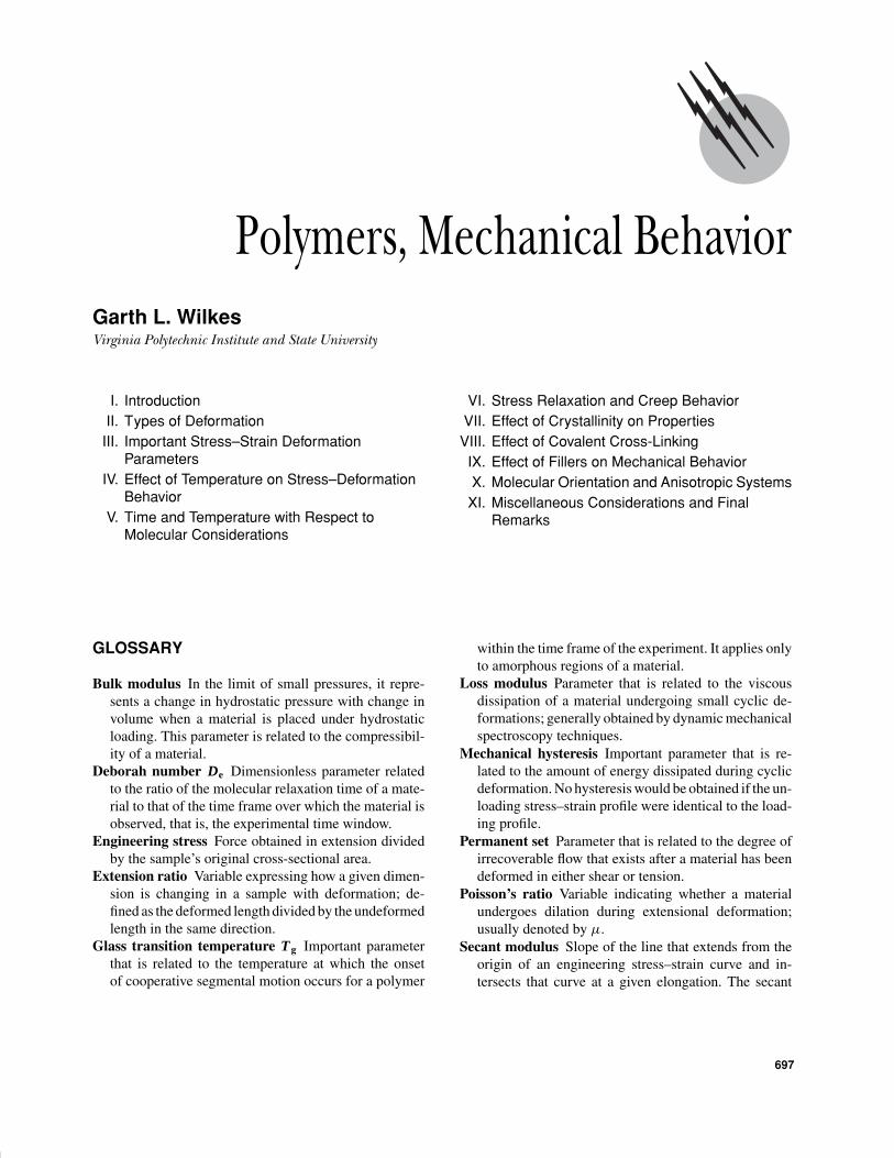
P1: GLM Final Pages Qu: 00, 00, 00, 00
Encyclopedia of Physical Science and Technology EN012c-598 July 26, 2001 15:59
Polymers, Mechanical BehaviorGarth L. WilkesVirginia Polytechnic Institute and State University
I. IntroductionII. Types of DeformationIII. Important Stress–Strain Deformation
ParametersIV. Effect of Temperature on Stress–Deformation
BehaviorV. Time and Temperature with Respect to
Molecular Considerations
VI. Stress Relaxation and Creep BehaviorVII. Effect of Crystallinity on PropertiesVIII. Effect of Covalent Cross-Linking
IX. Effect of Fillers on Mechanical BehaviorX. Molecular Orientation and Anisotropic SystemsXI. Miscellaneous Considerations and Final
Remarks
GLOSSARY
Bulk modulus In the limit of small pressures, it repre-sents a change in hydrostatic pressure with change involume when a material is placed under hydrostaticloading. This parameter is related to the compressibil-ity of a material.
Deborah number De Dimensionless parameter relatedto the ratio of the molecular relaxation time of a mate-rial to that of the time frame over which the material isobserved, that is, the experimental time window.
Engineering stress Force obtained in extension dividedby the sample’s original cross-sectional area.
Extension ratio Variable expressing how a given dimen-sion is changing in a sample with deformation; de-fined as the deformed length divided by the undeformedlength in the same direction.
Glass transition temperature Tg Important parameterthat is related to the temperature at which the onsetof cooperative segmental motion occurs for a polymer
within the time frame of the experiment. It applies onlyto amorphous regions of a material.
Loss modulus Parameter that is related to the viscousdissipation of a material undergoing small cyclic de-formations; generally obtained by dynamic mechanicalspectroscopy techniques.
Mechanical hysteresis Important parameter that is re-lated to the amount of energy dissipated during cyclicdeformation. No hysteresis would be obtained if the un-loading stress–strain profile were identical to the load-ing profile.
Permanent set Parameter that is related to the degree ofirrecoverable flow that exists after a material has beendeformed in either shear or tension.
Poisson’s ratio Variable indicating whether a materialundergoes dilation during extensional deformation;usually denoted by µ.
Secant modulus Slope of the line that extends from theorigin of an engineering stress–strain curve and in-tersects that curve at a given elongation. The secant
697

P1: GLM Final Pages
Encyclopedia of Physical Science and Technology EN012c-598 July 26, 2001 15:59
698 Polymers, Mechanical Behavior
modulus must be specified with respect to the degreeof deformation.
Shear modulus Initial slope of a shear stress–shear straindeformation curve; an indication of the resistance todeformation by shear.
Storage modulus Parameter that is related to the elas-tic behavior of a material when undergoing smallcyclic deformations; generally obtained by dynamicmechanical spectroscopy.
Strain Variable expressing how the dimensions of a ma-terial change under deformation.
Tensile strength Engineering stress at the point of samplefailure. In the case of sample tearing, generally the peakvalue of the engineering stress is quoted as the tensilestrength.
Thermal mechanical spectrum Graphic representationof a specific mechanical property as a function of tem-perature in which the data have been obtained under thesame loading rate. Generally, either the dynamic stor-age or loss modulus is reported. These values are ob-tained by either dynamic shear or extensional methods.
True stress Force of deformation obtained in extensiondivided by the cross-sectional area that exists at theelongation at which the stress is determined.
THE MECHANICAL BEHAVIOR of a material extendsfrom its stress–deformation response, in which the modeof deformation (uniaxial, biaxial, etc.) is particularly im-portant to define, as are the loading profile and environ-ment under which a given test is carried out. Often in theapplication of polymeric materials, the mode of failuremay be induced by a more complex loading scheme thanis easily applied within a testing laboratory. However, itis important to develop, where possible, a basic under-standing of the properties of any new polymeric materialthrough a well-defined loading profile and to learn howthese properties depend on molecular or “system” vari-ables as well as the nonmolecular or “external” variablesmentioned above.
I. INTRODUCTION
The mechanical behavior of polymeric materials is a vastsubject and one that is particularly important for the prac-tical application of these materials. Often it is the me-chanical properties, in conjunction with economics, thatdictate whether a given polymeric material can be utilizedfor a specific purpose. Other properties, such as opticaltransparency and dielectric behavior also play a signifi-cant role, but this article focuses only on the basics of me-chanical properties and, in particular, the means by which
these properties are measured and expressed. In addition,some of the molecular origin of the observed behavior isconsidered following basic definitions. Because of spacelimitations, only the basics are provided; hence, only theterminology and general characteristics of different be-havioral patterns of polymers in terms of their responseto internal (macromolecular) variables, such as molecularweight, chain topology, cross-linking, and crystallinity,will be considered along with the influence of externalparameters, such as temperature, time, and pressure, theformer two being of extreme importance.
Before we address the mechanical parameters and theirdefinition, a few comments are in order concerning themolecular systems that we will be discussing. In particu-lar, polymeric or macromolecular systems are composedof long chains whose backbone is made up either of likeunits (homopolymers) or of varied units (copolymers, ter-polymers, etc.), and if only two distinct ends are present thesystem is said to be linear. In many cases macromoleculesare not linear but may possess branches, which are shortor long, depending on the procedures used to synthesizethese materials. These branches can have a considerableeffect on mechanical properties since randomly placedbranch points will not fit into a crystal lattice. Therefore,the percentage of crystallinity is decreased by branching inthose systems that have otherwise suitable chain symme-try to pack into a lattice. In addition, these branch pointsalso influence the general flow properties of the system inmelt processing or solution processing particularly if thebranches are long enough to undergo entanglement withneighboring chains. Network structures are also commondue to cross-linking between chains if the reactants havesufficient functionality to promote network developmentat high conversion.
Many of the polymers utilized today in the market-place such as polyethylene, polypropylene, polystyrene,styrene–butadiene rubber, and polymethyl methacrylateare viewed as flexible or coil-like chains. This is due to theease of bond rotation in these covalently connected repeatunits, which can occur under appropriate conditions andare in contrast to rigid rod polymers where ease of bondrotation is highly limited at any reasonable temperatureat which the system would be used or processed. It isimportant to recognize the general “long-chain” natureof many of these materials. As an example, considera polyethylene molecule of 100,000 molecular weight.What would be the necessary tube length and tube dia-meter to place this molecule into if one were to stretch itout in its fully extended form (see Fig. 1)? For that mo-lecular weight a first-approximation calculation wouldshow that this number (length/diameter), or aspect ratioof the molecule, is of the order of 1800. This number farexceeds the same aspect ratio that would be obtained for
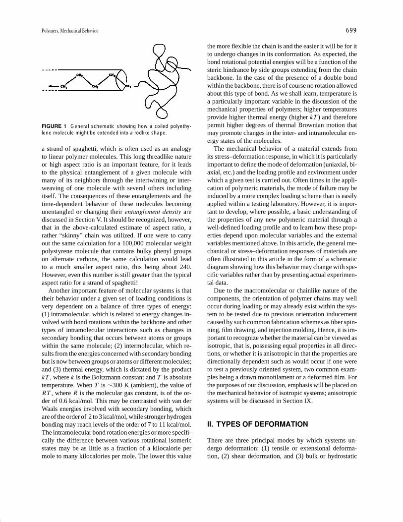
P1: GLM Final Pages
Encyclopedia of Physical Science and Technology EN012c-598 July 26, 2001 15:59
Polymers, Mechanical Behavior 699
FIGURE 1 General schematic showing how a coiled polyethy-lene molecule might be extended into a rodlike shape.
a strand of spaghetti, which is often used as an analogyto linear polymer molecules. This long threadlike natureor high aspect ratio is an important feature, for it leadsto the physical entanglement of a given molecule withmany of its neighbors through the intertwining or inter-weaving of one molecule with several others includingitself. The consequences of these entanglements and thetime-dependent behavior of these molecules becomingunentangled or changing their entanglement density arediscussed in Section V. It should be recognized, however,that in the above-calculated estimate of aspect ratio, arather “skinny” chain was utilized. If one were to carryout the same calculation for a 100,000 molecular weightpolystyrene molecule that contains bulky phenyl groupson alternate carbons, the same calculation would leadto a much smaller aspect ratio, this being about 240.However, even this number is still greater than the typicalaspect ratio for a strand of spaghetti!
Another important feature of molecular systems is thattheir behavior under a given set of loading conditions isvery dependent on a balance of three types of energy:(1) intramolecular, which is related to energy changes in-volved with bond rotations within the backbone and othertypes of intramolecular interactions such as changes insecondary bonding that occurs between atoms or groupswithin the same molecule; (2) intermolecular, which re-sults from the energies concerned with secondary bondingbut is now between groups or atoms or different molecules;and (3) thermal energy, which is dictated by the productkT , where k is the Boltzmann constant and T is absolutetemperature. When T is ∼300 K (ambient), the value ofRT , where R is the molecular gas constant, is of the or-der of 0.6 kcal/mol. This may be contrasted with van derWaals energies involved with secondary bonding, whichare of the order of 2 to 3 kcal/mol, while stronger hydrogenbonding may reach levels of the order of 7 to 11 kcal/mol.The intramolecular bond rotation energies or more specifi-cally the difference between various rotational isomericstates may be as little as a fraction of a kilocalorie permole to many kilocalories per mole. The lower this value
the more flexible the chain is and the easier it will be for itto undergo changes in its conformation. As expected, thebond rotational potential energies will be a function of thesteric hindrance by side groups extending from the chainbackbone. In the case of the presence of a double bondwithin the backbone, there is of course no rotation allowedabout this type of bond. As we shall learn, temperature isa particularly important variable in the discussion of themechanical properties of polymers; higher temperaturesprovide higher thermal energy (higher kT ) and thereforepermit higher degrees of thermal Brownian motion thatmay promote changes in the inter- and intramolecular en-ergy states of the molecules.
The mechanical behavior of a material extends fromits stress–deformation response, in which it is particularlyimportant to define the mode of deformation (uniaxial, bi-axial, etc.) and the loading profile and environment underwhich a given test is carried out. Often times in the appli-cation of polymeric materials, the mode of failure may beinduced by a more complex loading scheme than is easilyapplied within a testing laboratory. However, it is impor-tant to develop, where possible, a basic understanding ofthe properties of any new polymeric material through awell-defined loading profile and to learn how these prop-erties depend upon molecular variables and the externalvariables mentioned above. In this article, the general me-chanical or stress–deformation responses of materials areoften illustrated in this article in the form of a schematicdiagram showing how this behavior may change with spe-cific variables rather than by presenting actual experimen-tal data.
Due to the macromolecular or chainlike nature of thecomponents, the orientation of polymer chains may welloccur during loading or may already exist within the sys-tem to be tested due to previous orientation inducementcaused by such common fabrication schemes as fiber spin-ning, film drawing, and injection molding. Hence, it is im-portant to recognize whether the material can be viewed asisotropic, that is, possessing equal properties in all direc-tions, or whether it is anisotropic in that the properties aredirectionally dependent such as would occur if one wereto test a previously oriented system, two common exam-ples being a drawn monofilament or a deformed film. Forthe purposes of our discussion, emphasis will be placed onthe mechanical behavior of isotropic systems; anisotropicsystems will be discussed in Section IX.
II. TYPES OF DEFORMATION
There are three principal modes by which systems un-dergo deformation: (1) tensile or extensional deforma-tion, (2) shear deformation, and (3) bulk or hydrostatic

P1: GLM Final Pages
Encyclopedia of Physical Science and Technology EN012c-598 July 26, 2001 15:59
700 Polymers, Mechanical Behavior
deformation. In many tests, the loading profile can be ana-lyzed in terms of a combination of the above, but for sim-plicity we shall discuss each of these separately; we shallplace emphasis on the uniaxial mode of tensile deforma-tion since this is a particularly common procedure for test-ing the mechanical response of a solid system. (Polymerfluids and their mechanical response are most often char-acterized by simple shear deformation.)
These three modes of deformation are sketched inFigs. 2a–c. Only a uniaxial deformation scheme is illus-trated for tensile deformation, but biaxial or multiaxialtension behavior could occur. Furthermore, the shear de-formation mode shown is that for simple shear in whicha rotational component of the deformation exists, as isobvious if one “shears” a ball between one’s hands (i.e.,rotation occurs). No such rotation occurs in the case of ten-sile deformation of the same ball; rather, the deformationleads only to the shape of an ellipsoid if uniaxial defor-mation is applied—a quite different phenomenon than forthe simple shear. Thus, extensional deformation is an irro-tational deformation. This is the first indication that thereare likely to be differences in terms of the mechanicalresponse of materials when placed under a tensile modeof deformation in contrast to simple shear. Clearly, bulkdeformation carries no rotational component.
Referring to Fig. 2, let us define terminology that willhelp describe the mechanical response of the system. Con-sidering uniaxial tensile deformation at this point, if onedeforms a rubber band in this mode, there will be a positive
FIGURE 2 Three general types of deformation. (a) Tensile, (b)simple shear, and (c) bulk or hydrostatic compression.
force generated along the deformation axis that reflects theresistance to further deformation. If the amount or cross-sectional area of the rubber band is increased, the forcewill also increase for the same elongation. This suggeststhe need to normalize the size of the test specimen so thatthe results from specimens of different sizes can be com-pared. This is done by one of two approaches. The firstand most common is to divide the measured force by theinitial cross-sectional area of the test specimen. Referringto Fig. 2a, which shows deformation along the Z axis,this would be represented by dividing F by the productof l0x l0y . This product is the initial cross-sectional area,which we will denote by A0 and which is not a functionof deformation. This ratio of F /A0 provides what is com-monly known as the engineering stress σ0. Utilizing σ0
rather than the values of force will, in principle, lead tothe same result for the stress–elongation behavior of twoidentical materials irrelevant of their cross-sectional area.
A second means of defining stress is to use the truestress, denoted by σt. This parameter is defined as the forcedivided by the actual cross-sectional area A that exists atthe time the force is determined. Generally A is a functionof the degree of deformation, and this implies that it isnecessary to determine the cross-sectional area over theentire deformation range if true stress is to be expressed.As indicated in Fig. 3, for any material that undergoesconsiderable deformation, such as a rubber band, there isan ever increasing difference between the true stress andthe actual stress as deformation proceeds, because A is be-coming smaller with respect to A0 as elongation increases.The result is that, if one were to express the tensile strength(stress at break σB), there would be a considerable differ-ence between these two values depending on which choiceof stress were utilized; clearly the accurate value wouldbe that based on the true stress. However, for the sake
FIGURE 3 General plot of stress versus deformation showingthe difference between true and engineering stress in a uniformlydeforming system.
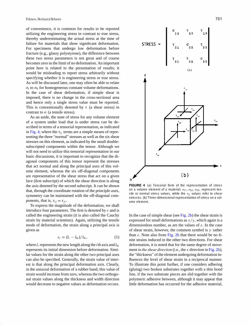
P1: GLM Final Pages
Encyclopedia of Physical Science and Technology EN012c-598 July 26, 2001 15:59
Polymers, Mechanical Behavior 701
of convenience, it is common for results to be reportedutilizing the engineering stress in contrast to true stress,thereby underestimating the actual stress at the time offailure for materials that show significant deformation.For specimens that undergo low deformation beforefracture (e.g., glassy polystyrene), the difference betweenthese two stress parameters is not great and of coursebecomes zero in the limit of no deformation. An importantpoint here is related to the presentation of results; itwould be misleading to report stress arbitrarily withoutspecifying whether it is engineering stress or true stress.As will be discussed later, one may often be able to relateσt to σ0 for homogeneous constant volume deformations.In the case of shear deformation, if simple shear isimposed, there is no change in the cross-sectional areaand hence only a single stress value must be reported.This is conventionally denoted by τ (a shear stress) incontrast to σ (a tensile stress).
As an aside, the state of stress for any volume elementof a system under load that is under stress can be de-scribed in terms of a tensorial representation, as indicatedin Fig. 4, where the τi j terms are a simple means of repre-senting the three “normal” stresses as well as the six shearstresses on this element, as indicated by the small double-subscripted components within the tensor. Although wewill not need to utilize this tensorial representation in ourbasic discussions, it is important to recognize that the di-agonal components of this tensor represent the stressesthat act normal and along the principal axes of this vol-ume element, whereas the six off-diagonal componentsare representative of the shear stress that act on a givenface (first subscript) of which the shear direction is alongthe axis denoted by the second subscript. It can be shownthat, through the coordinate rotation of the principle axes,symmetry can be maintained with the off-diagonal com-ponents, that is, τi j = τ j i .
To express the magnitude of the deformation, we shallintroduce four parameters. The first is denoted by ε and iscalled the engineering strain (it is also called the Cauchystrain by material scientists). Again, utilizing the tensilemode of deformation, the strain along a principal axis isgiven as
εi = (li − l0i )/ l0i , (1)
where li represents the new length along the i th axis and l0i
represents its initial dimension before deformation. Simi-lar values for the strain along the other two principal axescan also be specified. Generally, the strain value of inter-est is that along the principal deformation axis. Clearly,in the uniaxial deformation of a rubber band, this value ofstrain would increase from zero, whereas the two orthogo-nal strain values along the thickness and width directionwould decrease to negative values as deformation occurs.
FIGURE 4 (a) Tensorial form of the representation of stresson a volume element of a material; σ11 , σ22 , σ33, represent ten-sile or normal stress values, while the τi j values refer to shearstresses. (b) Three-dimensional representation of stress on a vol-ume element.
In the case of simple shear (see Fig. 2b) the shear strain isexpressed for small deformations as x /y, which again is adimensionless number, as are the values of ε. In the caseof shear strain, however, the common symbol is γ ratherthan ε. Note also from Fig. 2b that there would be no fi-nite strains induced in the other two directions. For sheardeformation, it is noted that for the same degree of move-ment in the shear direction (i.e., the x direction in Fig. 2b),the “thickness” of the element undergoing deformation in-fluences the level of shear strain in a reciprocal manner.To illustrate this point further, if one considers adhering(gluing) two broken substrates together with a thin bondline, if the two substrate pieces are slid together with thepolymeric adhesive between, although it may appear thatlittle deformation has occurred for the adhesive material,

P1: GLM Final Pages
Encyclopedia of Physical Science and Technology EN012c-598 July 26, 2001 15:59
702 Polymers, Mechanical Behavior
due to the thin bond line, considerable shear strain maywell have been imposed.
Returning to tensile deformation, the principal strainor deformation direction is correlated to another commonparameter that is often used to express the level of defor-mation, that is, the percent elongation:
% elongation = ε × 100. (2)
A third means of expressing deformation is to use theextension ratios or draw ratios, which we shall denote byλi . Three such values exist, one correlated to each of theprincipal axes. These are defined as
λx = lx / l0x ,
λy = ly / l0y , (3)
λz = lz / l0z .
In the limit of zero deformation, each λi takes on the valueof unity, in contrast to 0 for the respective values of εi .Hence, there is a numerical factor of unity that relates λi
to εi , that is,
λi = εi + 1. (4)
There are certain relationships between the λ terms thatare useful with regard to noting how the dimensions ofa specimen change in a given deformation. In particular,for materials that undergo a constant-volume deforma-tion, the product λx λy λz is unity. In fact, good elastomersnearly follow this behavior, and since they deform uni-formly (homogeneously), it can be shown that for uniaxialdeformation along z
λx = λy = λ−1/2z . (5)
The same approximation can often be used to define thedeformation of many other materials, although some erroris introduced, as pointed out in Section III.
Although the derivation will not be carried out here, itcan be shown that if a constant volume homogeneous ten-sile deformation occurs be it uniaxial, biaxial, etc., thenutilizing the fact that the product of the three extensionratios is unity, it follows that the true stress in a givenprincipal deformation direction is equal to the engineeringstress in that same direction multiplied by the respectiveextension ratio along that same axis. This can be a usefulrelationship to interconvert between true and engineeringstress when the assumption of constant volume deforma-tion is well approximated.
A final parameter describing the degree of deformationis the true strain εt. We establish this parameter by utilizinga differential form of our earlier definition of strain above,that is,
d εi = dli / li . (6)
Integration of Eq. (6) leads to
εt = ln(l / l0). (7)
One immediately notes that εt (also known as the Henkystrain) is also given by the natural logarithm of the re-spective extension ratio for the corresponding axis. In thedeformation behavior of polymeric systems, the true strainvariable is not often utilized and it is more common forone of the other three parameters to be quoted. However,some data do exist in the literature in the form of truestrain; this variable is quite different from the others dueto its logarithmic nature.
III. IMPORTANT STRESS–STRAINDEFORMATION PARAMETERS
The mode of tensile deformation will be used to elu-cidate some of the important parameters describing themechanical properties of a material. Figure 5 is a gen-eral sketch of a common stress–strain response exhib-ited by many polymeric materials—particularly ductilesemicrystalline materials like polyethylene or polypropy-lene. What can one extract from these data that mighthelp convey the mechanical response of the system andthat may be useful in deciding on the applicability ofa given material? Often, the values of σb and εb (seeFig. 5) will be of importance since these are related tothe stress at break and to the strain at break, the latter ofwhich can now easily be converted to percent elongation,the extension ratio, or true strain at break. The values σy
and εy are particularly important and should be distinctlynoted if this “peak” occurs in the stress–strain response.The respective stress and strain correlated with this peak
FIGURE 5 Generalized stress–strain curve that shows distinctyield.

P1: GLM Final Pages
Encyclopedia of Physical Science and Technology EN012c-598 July 26, 2001 15:59
Polymers, Mechanical Behavior 703
FIGURE 6 Schematic of a sample that undergoes necking anddrawing. (a) Undeformed, (b) necking has occurred with somedraw, and (c) neck is transformed throughout the material, gener-ating a uniform cross-sectional area in the drawn region.
are known as the yield stress and yield strain. These valuesare crucial, for they indicate the stress and strain beyondwhich a material will no longer return to its initial di-mensions; that is, plastic deformation or permanent setwill generally be induced in the material. The tensile de-formation of polyethylene utilized in the packaging of a“sick-pack” often leads to the formation of a “neck” andthe necked material will not recover its original dimen-sions (Fig. 6). Indeed, if a material displays a distinct yieldpoint or maximum in the stress–strain response as shownin Fig. 5, this almost certainly implies that a neck has beeninduced. It is apparent why engineering stress is a conve-nient indicator of the stress level since after inducement ofa neck, two distinct cross-sectional areas may reside withinthe material until the neck is transformed through the spec-imen. At the onset of neck inducement, if the force is nowdivided by the new cross-sectional area of the thinned-down region or necked region, the distinct peak shown inFig. 5 is often nearly removed, and hence the downturn inσ0 is often principally a result of our representation of thestress utilizing the initial cross-sectional area. Again re-ferring to Fig. 5, the region following the yield point mightimply that “strain softening” is occurring, but this is of-ten principally a result of the decrease in cross-sectionalarea and hence is not an entirely appropriate term to usefor such behavior. Following this downturn, however, thelong, rather uniform stress value obtained over consider-able deformation is the result of ductile or cold drawing ofthe material and represents the transformation of the neckthroughout the length of the sample (Fig. 6c). At the end ofthis transformation, an upturn is seen, which finally leadsto the point of failure, σb. This upturn can definitely be re-ferred to as strain hardening since it is the entire neck that
undergoes further elongation, and in the case of polymericsystems, this tends to promote further chain alignment ormolecular orientation until failure occurs at σb and εb.
A final parameter, which is very significant in Fig. 5,is the initial slope of the stress–strain curve. This slope iscalled Young’s modulus, the tensile modulus, or modulusof elasticity and is given the symbol E . By definition thiscan be written
E = limε→0
(d σ0 /d ε). (8)
This parameter is an index of the stiffness of the materialsince it represents the stress generated in the limit of smalldeformation. This stiffness parameter is particularly sig-nificant in this article. It might be pointed out that if thestress–strain curve displays an initial “toe” in its behaviorprior to it displaying a linear region, this is often due to apoorly mounted sample. As a result, the modulus wouldthen be determined from the linear region that is gener-ated following the “toe” as the sample “tightens up” inits initial stages of deformation. At this point it is alsosuitable to introduce the shear modulus and bulk modulus(refer to Fig. 2 for these modes of deformation). It followsfrom Figs. 2b and c that the shear modulus G and the bulkmodulus B are given, respectively, by
G ≡ limγ→0
(d τ/d γ ), (9)
B ≡ lim�P →0
[�P /(�V /V0)], (10)
where
�V = V0 − V . (11)
In the case of Eq. (10), the bulk modulus approachesinfinity as the material becomes incompressible, that is,�V = 0. Furthermore, the reciprocal of the bulk modu-lus is correlated with the thermodynamic isothermal com-pressibility of the material. Hence, the bulk modulus is avery fundamental parameter.
Another common parameter, one used particularly inthe industrial sector, is the secant modulus. By example,we shall define what is meant by the term 10% secant mod-ulus. In Fig. 7, a secant has been drawn from the origin tothe stress at 10% elongation. The slope of this line repre-sents the 10% secant modulus, and in this case it will beless than Young’s modulus. Similarly, other secant mod-uli could be defined by the slopes of similar lines taken toany point on the stress–strain curve, but it is obvious thatthe degree of elongation must be correlated to these calcu-lated slopes respectively. The use of secant modulus valueshelps convey information about the general stress–strainbehavior when the whole curve is not to be presented.
Returning to Fig. 5, another parameter to be definedis the energy for failure or rupture energy. The energy orwork of failure can be written

P1: GLM Final Pages
Encyclopedia of Physical Science and Technology EN012c-598 July 26, 2001 15:59
704 Polymers, Mechanical Behavior
FIGURE 7 Generalized stress–elongation plot illustrating how asecant modulus is calculated.
W =∫ lbreak
l0
f dl. (12)
Note that this integral is similar to the integration of astress–strain curve in that σ0 (σ0 = F /A0) carries the vari-able of force and strain represents length in an indirectmanner. To bring these two relationships together, first wedivide both sides of Eq. (12) by A0, which will bring σ0
into our relation. Realizing that
d ε = dl / l0 , (13)
we now make the appropriate substitution for dl inEq. (12) but must also recognize that l0 is specifically re-lated to the tensile direction and is not either of the dimen-sions involved with describing A0. Since this new length isa constant it can be moved outside the integral and dividedinto the left-hand side accordingly to give
W
V0= W
A0l0=
∫ εb
0σ0 d ε. (14)
Hence, the integral of a stress–strain curve based on engi-neering stress and engineering strain provides the energyof rupture normalized per unit volume V0 of the initialsample—a convenient result. Many modern instrumentsoften provide direct integration of a stress–strain curve,thereby giving the rupture energy as a commonly reportedparameter.
Figure 8 illustrates another common form of stress–strain behavior observed in many deformable polymers;note that no yield stress is observed. This behavior wouldbe common to many elastomeric systems. Although onlyone curve is provided for the loading cycle, three curves,A, B and C, are possible candidates for the unloading cy-cle. Which of these unloading cycles might occur, say, fora rubber band? This is an easy question to answer on thebasis of our discussion of the energy to break. Specifically,
FIGURE 8 Generalized stress–strain behavior for cyclic defor-mation. Curve B represents the loading path; curves A, B, and Care discussed in the text with respect to unloading pathways.
the area under the loading curve is the energy expendedinto deforming this system, and hence if curve A werethe associated unloading cycle, a higher energy under thatcurve would be returned than what was placed into the de-formation of the sample. That is, energy would be created,which is in opposition to the first law of thermodynamics.Curve B as an unloading cycle is also not expected sinceit would imply perfect reversibility and, in this case, dueto the nonlinear behavior the material would be describedas a nonlinear elastic material. This is not common in thecyclic deformation of real materials due to the molecu-lar slippage and segmental friction that dissipates some ofthe mechanical energy in the form of heat. Hence, curveC is the only expected path and this indicates that theenergy regained following deformation is less than thatexpended for the deformation. Because some of the en-ergy was stored and recovered while the remaining frac-tion was dissipated, this material would be described as anonlinear viscoelastic system, which is very common forthe behavior generally observed for polymeric materials.
This introduces the concept of mechanical hysteresis(MH). The percentage of mechanical hysteresis can beexpressed as
%MH =
∫σ0 dε −
∫σ0 dε
(loading) (unloading)∫σ0 dε
(loading)
× 100. (15)
This parameter is a direct measure of energy dissipated percycle (viscous behavior). Since the energy is dissipated inthe form of heat, we realize the practical significance ofmeasuring mechanical hysteresis in that it represents en-ergy that can no longer be recovered. It may also serveas a significant source of internal heating of a materialundergoing cyclic deformation. A prime example of me-chanical heating is the cyclic deformation of tires at high

P1: GLM Final Pages
Encyclopedia of Physical Science and Technology EN012c-598 July 26, 2001 15:59
Polymers, Mechanical Behavior 705
speeds. Due to the poor thermal conductivity of the poly-meric tire, the rise in temperature of the internal part ofthe tire can be considerable, and in fact severe degrada-tion would rapidly develop were it not for the appropri-ate chemical stabilizer package added during rubber com-pounding. Although hysteresis may be viewed somewhatas a disadvantage in some cases (i.e., generation of heat),it may also serve a useful role in helping to “dampen out”the transfer of energy in systems undergoing cyclic load-ing. For example, such damping materials might be uti-lized as vibrational mounts. Indeed, recognition of the hys-teresis properties of materials is very important in manyapplications.
It should be pointed out that hysteresis implies that theunloading cycle returns the system to its original dimen-sions. However, there is a somewhat looser use of thisterm in defining similar behavior for materials wherebythe initial dimensions are not totally recovered in the un-loading cycle. That is, permanent set or irrecoverable flow(unrecovered strain) may be introduced in the initial cycle(Fig. 9). However, the mechanical hysteresis as defined byEq. (15) is still a useful index.
We now ask if there is any relationship between the threefundamental moduli defined so far. For isotropic materi-als, there is a distinct relationship, but a new parameter,Poisson’s ratio, µ, must first be introduced. This can bedefined at small tensile deformation as
µ = −transverse strain/longitudinal strain. (16)
The longitudinal strain represents the principal deforma-tion axis, whereas either of the other two orthogonal direc-tions could be utilized for the transverse strain. The pur-pose of the negative sign is to generally make Poisson’sratio positive since the transverse strain will be negativebased on our earlier definitions. In brief, this parameter
FIGURE 9 General stress–strain behavior illustrating the phe-nomenon of permanent set.
implies how the material will change in volume in ten-sile deformation. (The volume does not change in simpleshear.) In brief, for an incompressible constant-volumedeformation behavior, µ equals 0.5, whereas for all otherisotropic systems, µ is less than 0.5 and usually rangesbetween 0.3 and 0.4 for glassy and semicrystalline poly-meric materials. For elastomers, however, µ may indeedapproach 0.5 and be as high as 0.496. An important pointto recognize is that as µ becomes less than 0.5, tensiledeformation of the material will cause an increase in vol-ume. At small deformation, this change in volume can bewritten
�V/V0 = (1 − 2µ)ε. (17)
From this relationship one notes that, when µ equals 0.5,there is no change in volume. Such behavior, along withuniform deformation, was the basis for the developmentof Eq. (5).
Regarding the dilation or volume increase, often in ten-sile testing a “whitening” of a material may be noted whereit has undergone deformation. This whitening, thoughsometimes caused by strain-induced crystallization, ismore often caused by the inducement of void formation,which leads to major fluctuations in refractive index rela-tive to the bulk material and hence opaqueness due to thescattering of light. Not all materials show this whiteningeffect even though the value changes occur, because thedilation may be more uniform in terms of the volume fluc-tuations. In other materials the changes in volume may beconsiderable on a local scale, leading to the lack of trans-parency. As an example, an increased turbidity often oc-curs in the ambient deformation of a common material likesemicrystalline high-density polyethylene or polypropy-lene, whereas during the tensile deformation of glassypolycarbonate, transparency is maintained even thoughthe volume initially increases with deformation.
With µ defined, we now can write the well-known re-lationship among the three moduli defined above for anisotropic material:
E = 2G(1 + µ) = 3B(1 − 2µ). (18)
(If the system is anisotropic, additional parameters areneeded to interrelate the moduli, which are directionallydependent.) This relationship shows that for incompress-ible materials E = 3G and that the bulk modulus must goto infinity. Since good elastomers have values of µ closeto 0.5, this upper limit is often a very good approximationin that an elastomer is three times stiffer in tension thanin shear. However, due to the fact that µ is typically be-tween 0.3 and 0.4 for glassy or semicrystalline systems, itfollows that Young’s modulus will still always be some-what greater than a factor of 2 above the shear modulus.This result is a strong indicator that, when a material is
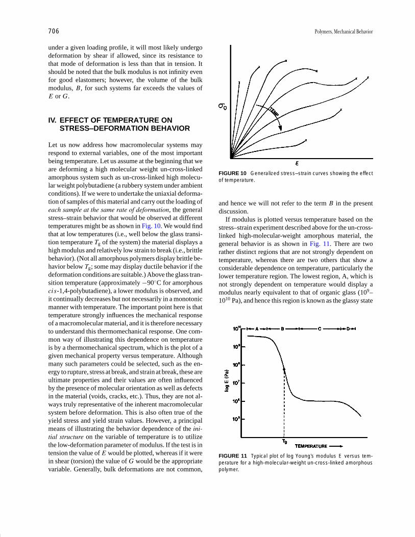
P1: GLM Final Pages
Encyclopedia of Physical Science and Technology EN012c-598 July 26, 2001 15:59
706 Polymers, Mechanical Behavior
under a given loading profile, it will most likely undergodeformation by shear if allowed, since its resistance tothat mode of deformation is less than that in tension. Itshould be noted that the bulk modulus is not infinity evenfor good elastomers; however, the volume of the bulkmodulus, B, for such systems far exceeds the values ofE or G.
IV. EFFECT OF TEMPERATURE ONSTRESS–DEFORMATION BEHAVIOR
Let us now address how macromolecular systems mayrespond to external variables, one of the most importantbeing temperature. Let us assume at the beginning that weare deforming a high molecular weight un-cross-linkedamorphous system such as un-cross-linked high molecu-lar weight polybutadiene (a rubbery system under ambientconditions). If we were to undertake the uniaxial deforma-tion of samples of this material and carry out the loading ofeach sample at the same rate of deformation, the generalstress–strain behavior that would be observed at differenttemperatures might be as shown in Fig. 10. We would findthat at low temperatures (i.e., well below the glass transi-tion temperature Tg of the system) the material displays ahigh modulus and relatively low strain to break (i.e., brittlebehavior). (Not all amorphous polymers display brittle be-havior below Tg; some may display ductile behavior if thedeformation conditions are suitable.) Above the glass tran-sition temperature (approximately −90◦C for amorphouscis-1,4-polybutadiene), a lower modulus is observed, andit continually decreases but not necessarily in a monotonicmanner with temperature. The important point here is thattemperature strongly influences the mechanical responseof a macromolecular material, and it is therefore necessaryto understand this thermomechanical response. One com-mon way of illustrating this dependence on temperatureis by a thermomechanical spectrum, which is the plot of agiven mechanical property versus temperature. Althoughmany such parameters could be selected, such as the en-ergy to rupture, stress at break, and strain at break, these areultimate properties and their values are often influencedby the presence of molecular orientation as well as defectsin the material (voids, cracks, etc.). Thus, they are not al-ways truly representative of the inherent macromolecularsystem before deformation. This is also often true of theyield stress and yield strain values. However, a principalmeans of illustrating the behavior dependence of the ini-tial structure on the variable of temperature is to utilizethe low-deformation parameter of modulus. If the test is intension the value of E would be plotted, whereas if it werein shear (torsion) the value of G would be the appropriatevariable. Generally, bulk deformations are not common,
FIGURE 10 Generalized stress–strain curves showing the effectof temperature.
and hence we will not refer to the term B in the presentdiscussion.
If modulus is plotted versus temperature based on thestress–strain experiment described above for the un-cross-linked high-molecular-weight amorphous material, thegeneral behavior is as shown in Fig. 11. There are tworather distinct regions that are not strongly dependent ontemperature, whereas there are two others that show aconsiderable dependence on temperature, particularly thelower temperature region. The lowest region, A, which isnot strongly dependent on temperature would display amodulus nearly equivalent to that of organic glass (109–1010 Pa), and hence this region is known as the glassy state
FIGURE 11 Typical plot of log Young’s modulus E versus tem-perature for a high-molecular-weight un-cross-linked amorphouspolymer.

P1: GLM Final Pages
Encyclopedia of Physical Science and Technology EN012c-598 July 26, 2001 15:59
Polymers, Mechanical Behavior 707
or glassy region of the thermal mechanical spectrum. Theother region that is not strongly dependent on temperaturewould display the properties and modulus behavior of asoft elastomer (105–106 Pa), and hence this region, C, isknown as the rubbery state or rubbery region of the spec-trum. The modulus decreases by a factor of between 1000and 10,000 on going from a glass to a soft elastomer—anextremely large change. For this reason the temperaturerange over which this change occurs is crucial in charac-terizing the mechanical properties of polymers. This tran-sition region is known as the glass transition region, andthe inflection point in Fig. 11 is typically taken as one in-dex of the glass transition temperature Tg—likely the mostimportant thermal mechanical transition that occurs in anamorphous material. The range of temperature over whichthis transition occurs for homopolymers may be as smallas 10 to 30◦C, and hence an awareness of the location ofthis transition is imperative with respect to the mechanicalapplications of a specific polymer.
Above the rubbery region is another, more strongly tem-perature dependent region, which is the viscous flow re-gion (see Fig. 11). In this thermal region, general polymermelt processing occurs for such amorphous materials (i.e.,100–200◦C above the glass transition temperature).
It must now be explained why we have chosen tobase this thermal mechanical spectrum on an amorphous,un-cross-linked high-molecular-weight polymer. Specif-ically, if cross-links were allowed such that an infinitenetwork structure (gel) developed, the viscous flow re-gion would be eliminated since an infinite network can-not undergo further softening or steady-state flow. Rather,such a material would display only an extension of therubbery region until the onset of degradation. If the ma-terial remained un-cross-linked but was of low molecularweight, there would be no rubbery plateau region observeddue to the fact that the molecular system did not have acritical length for the development of molecular entan-glements between the chains (Fig. 12). These entangle-ments are important for inducing the rubbery region inun-cross-linked systems. Finally, if crystallinity had beenpresent, a melting point Tm would enter the discussion,which of course would be located well above Tg. It shouldbe pointed out that the melting of crystals within a poly-meric material is typically not a sharp transition and infact can occur over tens of degrees in some materials. Al-terations in chain symmetry due to short-chain branches,the presence of added comonomer, and changes in stere-oregularity are some of the causes that lead to a broaddistribution in melting behavior but variation in coolingrate can also alter the perfection obtained within the crys-talline state, thereby also leading to a lowering of the melt-ing point and a broader distribution associated with thattransition.
FIGURE 12 Schematic of molecular structures of an amorphousmaterial having (a) molecular weight below the critical value forentanglements and (b) molecular weight above the critical valuefor entanglements.
Whereas crystallinity has a relatively small effect on themodulus below Tg of the amorphous phase, it has a stronginfluence above this thermal transition and in fact maycause the inflection point Tg in the modulus temperaturecurve to shift upward with increasing crystallinity. In ad-dition, the level of crystallinity will strongly enhance themodulus in the rubbery region between Tg and Tm. Abovethe melting point, however, the viscous flow state wouldonce again be reached as long as the semicrystalline sys-tem had not been cross-linked into an infinite network; ifso, it would likely show the modulus taking a value typicalof elastomers.
Recognition of the specific regions of the thermal me-chanical spectrum given above is crucial to understand-ing many of the mechanical properties of polymeric sys-tems. However, we first consider an additional variableand describe its influence on behavior. Let us return toFig. 10 and question how we might be able to gener-ate a similar series of stress–strain curves but at a con-stant temperature. The principal variable that makes thispossible is deformation rate. A familiar example of suchbehavior involves the polymeric “silly putty” materialthat one can obtain from a hobby shop. On the appli-cation of a low rate of extension or shear deformationof this material at ambient conditions, it will displaylow modulus and nearly liquidlike behavior. This impliesthat it would represent one of the low-modulus curvesin Fig. 10. However, if the same material is reformedinto a test specimen and deformed at a high rate of de-formation in either shear or extension, it will display amuch higher modulus and brittle fracture, thereby moreclosely representing one of the upper curves in Fig. 10.Hence, if the modulus behavior is plotted against de-formation rate, that is strain rate ε(d ε/dt) or shear rateγ (d γ /dt). Typically, because the range of deformationrates is considerable (several decades) it is more suitableto plot the modulus against the logarithm of the defor-mation rate constant temperature (Fig. 13). Granted, thespecific temperature chosen for the measurements willinfluence which rates are necessary for this behavior to be

P1: GLM Final Pages
Encyclopedia of Physical Science and Technology EN012c-598 July 26, 2001 15:59
708 Polymers, Mechanical Behavior
FIGURE 13 General plot of log modulus versus rate (or log rate)of deformation for many amorphous polymeric materials.
denoted. In Fig. 13 a mirror image of the behavior givenin Fig. 11 is observed, where rate of deformation was as-sumed constant and the temperature was then varied. Infact, since rate can be viewed as frequency (i.e., recip-rocal time), this clearly shows that time and temperatureare strongly interrelated, and we will have to address thisimportant fact. Before we do so, it is important to pointout that the variable of pressure may be used to influencethe stress–strain or modulus behavior at a constant tem-perature and deformation rate. As indicated in Fig. 14, fora process in which the temperature and rate are constant,an increase in the hydrostatic pressure will tend to pro-mote higher modulus behavior in general. These remarksare meant to be general, for there are some specific ef-fects of pressure that can be taken into account, such as itsinfluence on the melting point (Tm), Tg, etc. Also, some-times increased pressure can promote a higher strain tobreak. In brief, however, the effects of hydrostatic pressureon the general mechanical property behavior of polymersare not particularly important except in cases involvinghigh hydrostatic pressure, for example, in deep oceanicapplications.
FIGURE 14 Plot of stress versus strain for polypropylene beingmeasured at ambient temperature but at different hydrostatic pres-sures. [Reprinted with permission from Nielson, L. E. (1974). “Me-chanical Properties of Polymers and Composites,” Vol. 2, Dekker,New York. Copyright 1974 Marcel Dekker.]
V. TIME AND TEMPERATURE WITHRESPECT TO MOLECULARCONSIDERATIONS
To interrelate the variables of temperature and time (rate ofdeformation), we must focus on the types of materials weare discussing, that is, systems composed of macromole-cular chains. As mentioned earlier, the length-to-diameterratio, or aspect ratio, of linear polymers is considerableand is much greater by far than the typical strands ofspaghetti that are often used as an analogy for linear poly-mers. Besides this large mismatch in aspect ratio, there isanother major discrepancy in the common comparison ofmacromolecules with spaghetti. This concerns the lack ofmobility or motion of a spaghetti strand. A more suitableanalogy, and one that is consistent with developments inthe theories of reptation for the flow of polymer melts (vis-cous flow), compares linear polymers with long, stringyearthworms. Though somewhat crude and simplistic, thisanalogy has some merit in terms of the discussions that fol-low. In particular, long, stringy earthworms have many ofthe same response characteristics as polymer molecules.For example, placing them in liquid nitrogen would in-deed produce a more “glasslike material” whereas placingthem on a hot stove would tend to create a much higherdegree of motion (at least for a short time!) within theirbackbones similar to the effect of thermal energy (kT ) onmacromolecules. In fact, let us be so simplistic as to con-sider stress–strain experiments carried out on entangledworms if indeed they could be mounted into a suitablemechanical testing device. There is little doubt that, ata constant deformation rate, the variable of temperature(in the framework indicated above) would lead to stress–strain curves that would have the general characteristicsgiven by the same temperature function as indicated ear-lier in Fig. 10. The cause of the lower modulus and higherstrain behavior, in general, simply arises from the fact thatwithin the time scale of the experiment (constant loadingrate) the worms would have sufficient time to respond tothe imposed stress, thereby allowing some disentangle-ment and sliding of one backbone by another. The seg-mental friction would lead to a viscous dissipation, thatis, loss of mechanical energy. However, as the temper-ature decreased and the backbone motion of the wormsalso decreased (an analogy with less thermal Brownianmotion), there would be less chance for disentanglingin the same time-scale, and hence the general entangle-ment network character would provide a higher mod-ulus behavior similar to that noted for macromolecularsystems.
As can be imagined, varying the chemical structure ofa polymer can alter its conformational freedom or back-bone flexibility thereby influencing the average molecular
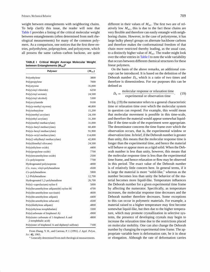
P1: GLM Final Pages
Encyclopedia of Physical Science and Technology EN012c-598 July 26, 2001 15:59
Polymers, Mechanical Behavior 709
weight between entanglements with neighboring chains.To help clarify this issue, the reader will note thatTable I provides a listing of the critical molecular weightbetween entanglements (often determined from melt rhe-ological measurements) for many of the common poly-mers. As a comparison, one notices that the first three en-tries, polyethylene, polpropylene, and polystyrene, whichall possess the same carbon–carbon backone, are quite
TABLE I Critical Weight Average Molecular Weightbetween Entanglements (Mwc)a
Polymer (Mwc)
Polyethylene 3800
Polypropylene 7000
Polystyrene 35,000
Poly(vinyl chloride) 6250
Poly(vinyl acetate) 24,500
Poly(vinyl alcohol) 5300
Polyacrylamide 9100
Poly(a-methyl styrene) 40,800
Polyisobutylene 15,200
Poly(methyl acrylate) 24,100
Poly(ethyl acrylate) 31,300
Poly(methyl methacrylate) 31,000
Poly(n-butyl methacrylate) 60,400
Poly(n-hexyl methacrylate) 91,900
Poly(n-octyl methacrylate) 114,000
Poly(2-ethylbutyl methacrylate) 42,800
Poly(dimethyl siloxane) 24,500
Poly(ethylene oxide) 4400
Poly(propylene oxide) 7700
Poly(tetramethylene oxide) 2500
Cis-polyisoprene 7700
Hydrogenated polyisoprene 4000
Cis, trans, vinyl-polybutadiene 4500
Cis-polybutadiene 5900
1,2-Polybutadiene 12,700
Hydrogenated 1,2-polybutadiene 26,700
Poly(ε-caprolactam) nylon 6 5000
Poly(hexamethylene adipamide) nylon 66 4700
Poly(decamethylene succinate) 4600
Poly(decamethylene adipate) 4400
Poly(decamethylene sebacate) 4500
Poly(diethylene adipate) 4800
Poly(ethylene terephthalate) 3300
Poly(carbonate of bisphenol A) 4900
Poly(ester carbonate of 1-bisphenol A and 48002-terephthalic acid)
Poly(ester of bisphenol A and diphenyl sulfone) 7100
From Zhang, Y. H., and Carreau, P. J. (1991). J. Appl. Polym.Sci. 42, 1965.
a Generally determined from melt rheological measurements.
different in their values of Mwc. The first two are of rel-atively low Mwc, this is due to the fact these chains arevery flexible and therefore can easily entangle with neigh-boring chains. However, in the case of polystyrene, it haslarge bulky phenyl groups on alternate backbone carbonsand therefore makes the conformational freedom of thatchain more restricted thereby leading, as the usual case,to a distinctly higher value of Mwc. The reader might lookover the other entries in Table I to note the wide variabilitythat occurs between different chemical structures for theselinear polymers.
On the basis of the above remarks, an additional con-cept can be introduced. It is based on the definition of theDeborah number De, which is a ratio of two times andtherefore is dimensionless. For our purposes this can bedefined as
De = molecular response or relaxation time
experimental or observation time. (19)
In Eq. (19) the numerator refers to a general characteristictime or relaxation time over which the molecular systemin question can respond. For example, this would meanthat molecular movement is possible in this time-scale,and therefore the material would appear somewhat liquid-like if the time-scale of the experiment were appropriate.The denominator concerns the time frame over which theobservation occurs, that is, the experimental window orobservation time. In brief, if the Deborah number is greaterthan unity, this means that the molecular response time islonger than the experimental time, and hence the materialwill behave or appear more as a rigid solid. When the Deb-orah number is less than unity, however, this means thatthe molecular response time is less than the experimentaltime frame, and hence relaxation or flow may be observedin this period. The exact value of the Deborah numberis of relatively little concern here. In general terms, if itis large the material is more “solid-like,” whereas as thenumber becomes less than unity the behavior of the ma-terial becomes more liquid-like. Temperature influencesthe Deborah number for a given experimental time frameby affecting the numerator. Specifically, as temperatureincreases, the molecular response time decreases and theDeborah number therefore decreases. Some exceptionsto this can occur in polymeric materials. For example, amaterial raised to a higher temperature may first becomesomewhat liquid-like, but then due to the higher tempera-ture, which may promote crystallization in selective sys-tems, the presence of developing crystals may begin toincrease the relaxation time due to the restrictions placedon molecular mobility. One can also change the Deborahnumber by changing the experimental time frame. The ap-propriate variable here is deformation rate, be it in shearor elongation. Although the rate of deformation carries

P1: GLM Final Pages
Encyclopedia of Physical Science and Technology EN012c-598 July 26, 2001 15:59
710 Polymers, Mechanical Behavior
reciprocal time, increasing this variable essentially short-ens the observation time scale and hence decreases thedenominator in Eq. (19). Now whereas the denominatoris controlled specifically by the observation time, whichis inversely related to deformation rate, the numerator iscontrolled by many factors, many of which extend frominternal variables such as molecular weight, cross-linking,molecular architecture, chain stiffness as related throughchain chemistry, and crystallinity. As mentioned earlier, itis important to recognize the balance between three typesof energy: intermolecular, intramolecular, and thermal en-ergy. Indeed, the numerator in Eq. (19) is highly dependenton the balance of these energies. In summary, the Deborahnumber concept is important for rationalizing the mechan-ical behavior of a polymeric material when tested underdifferent loading rates and environmental conditions.
Utilizing our earthworm concept of polymeric species,let us strengthen our understanding of the effect of defor-mation rate. Suppose we hold temperature constant, forexample, at ambient temperature, and carry out a seriesof stress–strain experiments, but the changing variable isnow deformation rate, be it in shear or extension. There islittle doubt that again the response expected would mimicwhat is displayed in Fig. 10. At low rates of deformation,due to the backbone motion of the worms, they could movewithin the time frame of a slow deformation experiment,thereby leading to considerable strain and low-modulusbehavior. On the other hand, at very high rates of defor-mation, there is little doubt as to what the result would be!Crude as the analogy seems, the response of the wormswould now provide a higher modulus due to the inabil-ity to disentangle, thereby leading to chain scission andmore brittle-like behavior similar to what we discussedearlier with reference to the “silly putty” polymeric ma-terial. Indeed, one can show that chain scission occursin real macromolecular systems under suitable rates andtemperatures by utilizing electron spin resonance studiesto reveal the presence of free radicals generated by thebreaking of covalent bonds.
With this somewhat simplistic but useful earthwormanalogy we have a firm grasp of the general interplay be-tween temperature and loading rate. Our desire now is toquantify the relative degree of storage of mechanical en-ergy or (elastic behavior) caused by an entangled network-like behavior in contrast to the dissipation of mechani-cal energy (viscous dissipation) through chain slippageand general segmental frictional forces that are related toimportant mechanical properties, such as hysteresis, dis-cussed earlier. A common way to quantify the relativedegree of the viscous and the elastic components in theseviscoelastic materials is by means of dynamic mechanicalanalysis (DMA) techniques. This approach allows a di-rect measurement of these two components generally by
using low-strain deformations that are carried out over arange of both temperature and frequency. The basics ofthe technique are best explained by first considering theresponse of a pure elastic body to an oscillatory dynamicstrain such as is expressed by
ε(t) = ε0 sin(ωt), (20)
where ω = 2π frequency. A linear elastic body would bethat of a Hookean spring whose relationship of strain tostress in tension is given by
σ0(t) = E ε(t). (21)
This relationship clearly shows that the stress on the sys-tem is a function only of the displacement and carriesno other time-dependent characteristics. Hence, withEq. (20) for the time-dependent strain, the time-dependentHookean stress becomes
σ0(t) = E ε0 sin(ωt). (22)
Hence, a general plot of these two functions togetherwould appear as shown in Fig. 15a. Note that the amplitudeof the stress function varies in proportion to its modulusbut that both the stress and strain oscillate in phase; thatis, a zero phase angle exists.
To represent a linear viscous body, Newton’s law ofviscosity suffices, which can be stated in tension as
σ0(t) = η(d ε/dt), (23)
where η represents a Newtonian viscosity; that is, it is in-dependent of the deformation rate. Utilizing this equationin conjunction with Eq. (20) for the time-dependent strainshows that the time-dependent stress for a purely viscousmaterial is
σ0(t) = ηωε0 cos(ωt), (24)
which is strikingly different in its time-dependent behaviorfrom the Hookean stress elastic response. In particular, theamplitude now varies linearly with the deformation rate(frequency), a factor that had no importance in the elas-tic or Hookean behavior. Particularly important is the factthat, for a purely viscous response, the stress and strainare out of phase by 90◦ (see Fig. 15b). (The stress will“lead” that of the strain, since the material will not un-dergo deformation without sensing stress.) It then shouldbe obvious that, if a viscoelastic material is placed underan oscillatory deformation at small strains where its re-sponse should be linear, and if one can monitor the stressand strain response via suitable electronic techniques, thiswill allow a direct measurement of the phase angle be-tween these two functions. This measurement will clearlyprovide a direct measure of the viscous response. As onemight expect, a viscoelastic polymer undergoing cyclic

P1: GLM Final Pages
Encyclopedia of Physical Science and Technology EN012c-598 July 26, 2001 15:59
Polymers, Mechanical Behavior 711
FIGURE 15 Generalized behavior of the phase relationship be-tween stress and strain in a sinusoidal loading experiment. (a)Hookean or pure elastic behavior, (b) Newtonian or pure viscousbehavior, and (c) viscoelastic behavior, which is typical of poly-meric materials.
or dynamic loading as a function of temperature will dis-play a finite phase angle whose magnitude is dependent onboth the loading rate and temperature (Fig. 15c). (Thinkof how the worms would react.) Such dynamic loadingpatterns are characterized by the dynamic modulus (E ∗
and G ∗) written below in terms of both tensile and sheardeformation:
E ∗ = E ′ + iE ′′, (25a)
G ∗ = G ′ + iG ′′. (25b)
The conventional symbolism used here represents com-plex plane notation, where i denotes the square root of −1and is of little importance in our discussion. Rather, it ismost suitable for us to view E ∗ or G ∗ as a vector quantitymade up of both the viscous and elastic components, as in-dicated in Fig. 16, where the respective elastic component(E ′ or G ′) and viscous component (E ′′ or G ′′) lie alongthe x and y axes, respectively. It therefore follows that thephase angle will be denoted by δ, and thus we reach theobvious and important result that
tan δ = E ′′/E ′ = G ′′/G ′. (26)
Hence, measurement of the phase angle provides a directratio of the viscous (loss) to elastic (storage) components,and this is a useful parameter for describing the mechani-cal response of a material under a given loading rate andtemperature. It should also be clear that, due to the in-terrelationship of tan δ and the respective viscous and
elastic components, only two of the three quantities areindependent, and thus all three are usually not reported.Generally, the elastic component and one of the other twoparameters, either tan δ or E ′′ (or G ′′) are given.
Some specific examples of such a response obtainedin dynamic testing are shown in Figs. 17a–c. Some sig-nificant observations can be made. First, under dynamicconditions the elastic component E ′ displays the samecharacteristics as the modulus term discussed above interms of the thermal mechanical spectrum, and in fact thetwo are essentially the same if the time frame of mea-surement is equal for both. Hence, the dynamic mechan-ical technique is very convenient and useful for generat-ing the thermal mechanical spectrum. Second, tan δ (seeFig. 17c) or E ′′ displays various maxima as a functionof temperature, indicating distinct “loss peaks.” Note thatsome peaks occur below the glass transition temperature,whereas the major loss peak is typical at the glass transi-tion. In fact, for un-cross-linked materials that are amor-phous, tan δ at Tg will be of the order of 1.0 or somewhatabove, indicating that the viscous component is equal toor exceeds that of the elastic component [recall Eq. (26)].Above the glass transition temperature, however, the gen-eral loss again decays as is indicated, even though thematerial shows higher mobility due to the enhancementof thermal energy (i.e., increased kT ). If this is surpris-ing, the reader may view it in the following framework.At a suitable rate and temperature, the dynamic loadingresonates with the motion of the macromolecular sys-tem, whose rapidity of motion increases as temperatureincreases. At the glass transition temperature these localmodes of motion within the macromolecular chain canbe somewhat viewed as being in phase with the applieddynamic loading. Hence, “mechanical resonance” results,leading to a considerable absorption of energy and highvalues of tan δ. However, with enhanced thermal motion,there is a dephasing of the applied dynamic loading withthat of the molecular motion, and a decrease in tan δ
occurs as E ′ (or G ′) decreases. It is clear that there isa further softening of the material by enhanced motion
FIGURE 16 General plot showing the vectorial relationship be-tween the loss and storage parts (E′′ and E′) with respect to thedynamic Young’s modulus E∗. The phase angle between thesetwo quantities is denoted by δ.
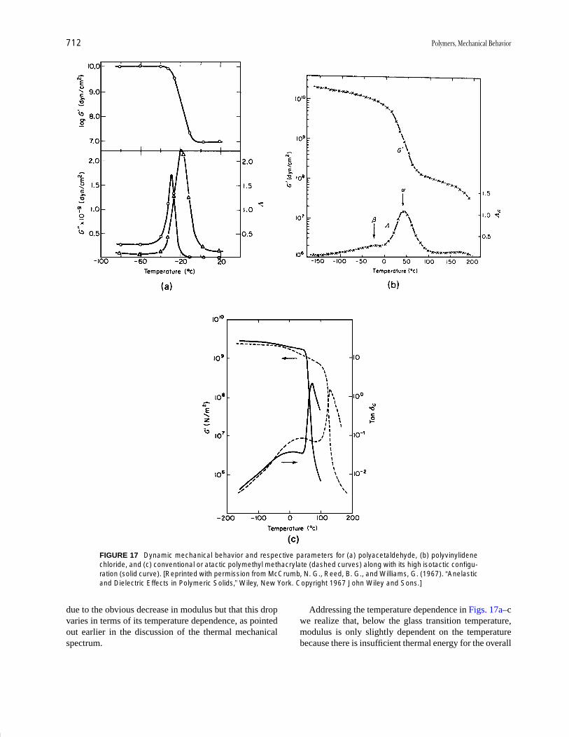
P1: GLM Final Pages
Encyclopedia of Physical Science and Technology EN012c-598 July 26, 2001 15:59
712 Polymers, Mechanical Behavior
FIGURE 17 Dynamic mechanical behavior and respective parameters for (a) polyacetaldehyde, (b) polyvinylidenechloride, and (c) conventional or atactic polymethyl methacrylate (dashed curves) along with its high isotactic configu-ration (solid curve). [Reprinted with permission from McCrumb, N. G., Reed, B. G., and Williams, G. (1967). “Anelasticand Dielectric Effects in Polymeric Solids,” Wiley, New York. Copyright 1967 John Wiley and Sons.]
due to the obvious decrease in modulus but that this dropvaries in terms of its temperature dependence, as pointedout earlier in the discussion of the thermal mechanicalspectrum.
Addressing the temperature dependence in Figs. 17a–cwe realize that, below the glass transition temperature,modulus is only slightly dependent on the temperaturebecause there is insufficient thermal energy for the overall

P1: GLM Final Pages
Encyclopedia of Physical Science and Technology EN012c-598 July 26, 2001 15:59
Polymers, Mechanical Behavior 713
cooperative segmental motion of the backbone, that is, a“crank shaft” type of motion, which would lead to a muchlarger scale mobility and potential flow. However, theremay be sufficient thermal energy to provide the onset oflocal-scale motions such as the rotation of side groups,oscillations of side groups, and oscillations and partialtorsional rotations of backbone components. All of thesemotions lead to the dissipation of energy, and hence adistinct loss peak is noted in the thermal mechanical spec-trum. These low-temperature loss peaks are considered tohave great significance because their magnitude and num-ber represent molecular means by which energy can bedissipated in the glassy state. We shall return to this dis-cussion when we consider impact properties. It should bementioned in passing that the two techniques of dielectricspectroscopy and solid-state NMR are also used consider-ably, since these methods can provide information on thelocal molecular motions discussed above.
If a material is amorphous, it is not likely that addi-tional loss mechanisms will be observed above the glasstransition temperature, although there has been some con-troversy relating to this point. If, however, crystallinityis present within the system, additional loss mechanismsmay well be observed due to motions within the crystalphase or at the crystal interface. These motions are of im-portance in terms of the mechanical response of the crys-talline phase under loading conditions and in fact mayplay a considerable role in determining the appropriatedraw temperatures in the mechanical processing of fibersand films. The magnitude of these crystalline loss mech-anisms can be influenced by the thermal processing his-tory, as might be expected, since this will influence crystalperfection.
From our discussion of dynamic mechanical spectrosc-opy and its correlation with the time–temperature responseof macromolecular systems, it now should be obvious howa dynamic mechanical spectrum will change as the fre-quency of loading is increased. This is illustrated in Fig. 18and should come as no surprise in view of our discussionof the response of “earthworms.” The spectrum is shiftedupscale on the temperature axis as the rate of deformationis increased. This, of course, follows from the fact that, formotion to occur and allow a lowering of modulus, a higherdegree of thermal energy and faster molecular motion willbe required for the experiment with the highest loadingrate or shortest time frame (recall our discussion of theDeborah number). In fact, a general rule is that the glasstransition temperature, as denoted by either the maximumin E ′′ or tan δ (as well as the inflection point in E ′) will shiftroughly 3–5◦C per decade of loading rate increase. Thesame rule, however, does not directly apply to the sub-Tg
or crystal loss peaks accordingly. It should be mentionedthat the transition peak in tan δ typically appears at a higher
FIGURE 18 Plot of the real part of the dynamic Young’s modulusversus temperature for atactic polyvinyl chloride as obtained atfour different frequencies (—–, 5 cps; — —, 50 cps; — · —, 500cps; - - -, 5000 cps). [Reprinted with permission from Aklonis, J. J.,and McKnight, W. J. (1983). “Introduction to Polymer Viscoelastic-ity,” 2nd ed., Wiley-Interscience, New York. Copyright 1983 JohnWiley and Sons.]
temperature than the corresponding peak in E ′′. Thus,when reporting a transition temperature as determined byDMA, one must specify which parameter is utilized.
The sub-Tg loss peaks are generally more dependent onloading rate or frequency and, in fact, analysis shows that,as loading rate increases, the lower temperature loss mech-anisms shift more rapidly upward toward the glass transi-tion response peak. This response with deformation rateis denoted by a plot of the logarithm of the dynamic fre-quency versus the reciprocal temperature where the peaktemperature in E ′′ or tan δ is indicated. An example of thisis illustrated in Figs. 19a and 19b, which show the spectraobtained for a cross-linked epoxy at different frequenciesand the corresponding 1/T (Arrhenius) plot to indicate thefrequency response. Typically, linear or near linear behav-ior is observed in Fig. 19b for this plot, the slope of whichtherefore provides an activation energy—an index of thefrequency or temperature dependence. This works par-ticularly well for sub-Tg loss peaks that follow Arrheniusbehavior. However, due to the non-Arrhenius nature of theglass transition, this form of analysis is less reliable whenapplied to the glass transition region. The general shape ofthe modulus temperature curve in Fig. 19a is not altered

P1: GLM Final Pages
Encyclopedia of Physical Science and Technology EN012c-598 July 26, 2001 15:59
714 Polymers, Mechanical Behavior
FIGURE 19 (a) Plot of the real part of dynamic Young’s modulusE ′ versus temperature for a lightly cross-linked epoxy (1◦C/min).The three intermediate lines represent intermediate frequencieswith respect to the two that are labeled. (b) Plot of log frequencyversus 1/Tmax for the same epoxy material. The Tmax values wereobtained from the tan δ data not shown. [Reprinted with permis-sion from Wetton, R. E., and Stone, M. R. (1983). Proc. Trans.Relax. Polym. Mater., Melbourne, 1983.]
greatly with a change in frequency. However, this is not toindicate that there is no change, for in fact the breadth ofthe transition may often undergo alteration over a range ofloading frequencies. This clearly must be correlated witha distribution in the relaxation times associated with thespecific mechanism responsible for a given loss peak, beit a side group rotation, cooperative backbone motion, orotherwise.
A. Factors Influencing Dynamic Loss Behavior
As might be expected, variables that affect dynamic me-chanical behavior are such important factors as level ofcross-linking, the presence of plasticizer, and phase sep-aration as may occur in block or segmented copolymers,polymer blends, and semicrystalline systems. Though wecannot explore all of these effects, we shall make a few
important points. Cross-linking tends to decrease the mag-nitude of the glass transition, loss behavior and sometimescauses it to broaden, as might be expected due to an influ-ence on the spreading of the relaxation times for coopera-tive backbone motion. Addition of plasticizer tends to de-crease the glass transition temperature and often broadenthe loss response, although different plasticizers functionin quite different ways in influencing the breadth of therespective loss behavior. This allows some control of thethermal range over which damping occurs. Antiplasti-cizers can, in fact, depress or eliminate one or more ofthe sub-Tg loss responses due to limiting the mobility ofthe corresponding molecular group responsible for thattransition.
As a final example demonstrating the utility of dynamicmechanical spectra, let us consider the impact behaviorof polymeric systems. It is well known that bisphenol Apolycarbonate is a very high impact glassy polymer underambient conditions, whereas atactic polystyrene is a brittleglass under similar high loading rate or impact conditions.The glass transition temperature of polycarbonate at lowfrequencies is ∼150◦C, whereas that of polystyrene istaken to be ∼100◦C; hence, polycarbonate can be viewedas 50◦ “deeper” in the glassy state than polystyrene atroom temperature. The latter phrase should be takenlightly and is meant only to elucidate the difference be-tween these two polymers in terms of impact properties.That is, the impact characteristics do not arise from the factthat polystyrene has a lower Tg! Specifically, the dynamicmechanical spectrum of bisphenol A polycarbonate isshown in Fig. 20. Bisphenol A polycarbonate displays aparticularly strong sub-Tg dissipation mechanism, whichmay well assist in dissipating energy when the glass israpidly loaded. Polystyrene displays a low-temperatureloss mechanism, but it is not of great magnitude; hence,this polymer exhibits less mobility in the glassy phase(data not shown). This indicates the potential use of dy-namic mechanical spectroscopy in looking for differencesin dissipative modes of energy below the glass transitiontemperature. Another important feature is apparent fromFig. 21, which illustrates the frequency dependence of theloss peaks of polycarbonate. In particular, due to the strongsensitivity of the sub-Tg peak to loading rate, the peakrapidly shifts upward under high loading rate conditionsand may well be operative under ambient conditions asa prime source for dissipating mechanical energy placedinto the material. The actual mechanism is more complex,but the point here is to illustrate the worth of dynamicmechanical spectroscopy in light of a very importantmechanical property, namely, impact strength. Note thatthe loss peak associated with Tg shifts upscale withloading rate at only about 3 to 5◦C/decade, as discussedearlier.
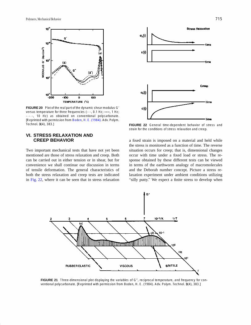
P1: GLM Final Pages
Encyclopedia of Physical Science and Technology EN012c-598 July 26, 2001 15:59
Polymers, Mechanical Behavior 715
FIGURE 20 Plot of the real part of the dynamic shear modulus G′versus temperature for three frequencies (- - -, 0.1 Hz; ——– , 1 Hz;- · - · -, 10 Hz) as obtained on conventional polycarbonate.[Reprinted with permission from Boden, H. E. (1984). Adv. Polym.Technol. 3(4), 383.]
VI. STRESS RELAXATION ANDCREEP BEHAVIOR
Two important mechanical tests that have not yet beenmentioned are those of stress relaxation and creep. Bothcan be carried out in either tension or in shear, but forconvenience we shall continue our discussion in termsof tensile deformation. The general characteristics ofboth the stress relaxation and creep tests are indicatedin Fig. 22, where it can be seen that in stress relaxation
FIGURE 21 Three-dimensional plot displaying the variables of G′′, reciprocal temperature, and frequency for con-ventional polycarbonate. [Reprinted with permission from Boden, H. E. (1984). Adv. Polym. Technol. 3(4), 383.]
FIGURE 22 General time-dependent behavior of stress andstrain for the conditions of stress relaxation and creep.
a fixed strain is imposed on a material and held whilethe stress is monitored as a function of time. The reversesituation occurs for creep; that is, dimensional changesoccur with time under a fixed load or stress. The re-sponse obtained by these different tests can be viewedin terms of the earthworm analogy of macromoleculesand the Deborah number concept. Picture a stress re-laxation experiment under ambient conditions utilizing“silly putty.” We expect a finite stress to develop when

P1: GLM Final Pages
Encyclopedia of Physical Science and Technology EN012c-598 July 26, 2001 15:59
716 Polymers, Mechanical Behavior
a rapid fixed strain is imposed on the material but real-ize that this stress would quickly decay due to the fairlyrapid flow and sliding of the polymer macromolecules un-der ambient conditions (it displays a low Deborah num-ber). This would lead to a zero stress in a short periodof time. Similarly, if a fixed load were placed on the“silly putty” material, we would anticipate that the ma-terial would undergo deformation with time (creep) butnot necessarily in a linear fashion. The initial responsewould likely be somewhat elastic, but due to the capac-ity of these macromolecules to flow at room conditions,the material dimensions would increase quite rapidly withtime.
Let us contrast the behavior of the “silly putty” withthat of a cross-linked rubber band. In stress relaxation onewould anticipate that some rapid decay in stress wouldoccur due to the slipping of chain entanglements as wellas any loose chains or loops that make up the network.However, an equilibrium stress value would be obtainedfollowing the completion of the relaxation of these loosechain ends, loops, or un-cross-linked chains within thesystem. That is, the final “fish net” or gel macromolecularstructure would reach an equilibrium stress value at somelater time. With respect to the same material response increep, one would expect a quick rise in strain due to theimposition of a load, but the strain would then rise muchmore slowly and reach a final equilibrium value at the point
FIGURE 23 Three-dimensional plot illustrating the relationship between strain to break, log strain rate, and molecularweight for conventional polycarbonate as determined at ambient conditions. [Reprinted with permission from Morton,J. R., Johnson, J. F., and Cooper, A. R. (1972). J. Macromol. Sci. Rev. Macromol. Chem. C8(1), 57.]
where all chain entanglement effects had been relaxedout and again the “fish net”or gel structure served as theresistance for further deformation.
A final example is that of a cross-linked epoxy ma-terial or glassy network at room temperature. Here onewould expect relatively little stress relaxation in shorttimes, even if un-cross-linked chains existed in the system.That is since we are below the glass transition tempera-ture, large-scale cooperative motion cannot occur rapidlywithin the same time frame as in the preceding exper-iment (a large Deborah number is displayed). With re-spect to the creep behavior of this cross-linked glass,one would also expect very little strain to result andlittle change with time for reasons that should be en-vious. It should then be evident that the tests of stressrelaxation or creep, coupled with the variables of tem-perature and time, serve as convenient methods withwhich to monitor the viscoelastic response of polymericsystems.
These response times will be influenced accordinglyby levels of cross-linking, crystallinity, molecular weight,molecular chain architecture (branched versus linear)plasticizer content, and so on, as is clear from the argu-ments based on wormlike motions. These same variablesshould be considered with respect to ultimate propertiesand yield behavior, as well as the low deformation (mod-ulus) response. As an example, consider Fig. 23, which

P1: GLM Final Pages
Encyclopedia of Physical Science and Technology EN012c-598 July 26, 2001 15:59
Polymers, Mechanical Behavior 717
shows the strain at break (ultimate property) as a func-tion of molecular weight at a given temperature. Thereis a decrease in the strain at break for this polycarbon-ate system as rate is increased in this range of ε as ex-pected. A particularly important point is that, at a fixedε, there is a major change in behavior above a criticalmolecular weight, which is of the order of 10,000 g/molfor this material. This critical molecular weight occurswhere the length of these macromolecules is sufficientto promote molecular entanglements, which in turn leadto a pseudo network—a more useful material for struc-tural applications. This critical molecular weight variesfor different macromolecular chain chemistry dependingon the relative chain stiffness and the mass of the repeatunit.
VII. EFFECT OF CRYSTALLINITYON PROPERTIES
Because many of today’s polymers are semicrystalline,we shall discuss briefly how crystallinity influences me-chanical properties, as well as other important propertiessuch as optical transparency. Let us first consider the ef-fect of crystallinity on stiffness or modulus behavior. Ifthe system is unoriented (oriented systems will be dis-cussed in Section X) and if one is below the glass transi-tion temperature of the amorphous phase, increasing thecrystallinity of a material has relatively little effect onmodulus; that is, modulus will be of the order of 109 to1010 Pa, regardless of the level of crystallinity. On theother hand, if one is above the glass transition temper-ature of the remaining amorphous component, the pres-ence of crystallinity will strongly influence modulus andcause it to increase accordingly, as long as one is belowthe melting point of the crystals. A general sketch of thisbehavior is illustrated in Fig. 24, where the general ther-mal mechanical behavior is shown with respect to level ofcrystallinity.
If stress–strain measurements were being made abovethe glass transition temperature of the amorphous phase,the modulus would be enhanced in these measurements aswell, but so would other properties such as strain to breakand stress at break. In the presence of crystallinity, a dis-tinct yield point is often displayed (see Fig. 5). Generally,the presence of crystallinity may also strongly influencethe nature of cold drawing or ductile flow, although thecrystallinity does not have to exist for this phenomenonto occur. It certainly must, however, if a yield or ductilecharacter is to be observed above the glass transition for anonfilled homopolymeric material. Crystallites also servebasically as “physical cross-links” and therefore stronglydominate the mechanical properties above Tg. It is not our
goal to discuss the morphological textures of semicrys-talline polymers, but it is important to point out that byvarying the methods of crystallization (quench rates, etc.)one can change the morphological textures in a givenpolymer, thereby affecting the mechanical behavior eventhough the level of crystallinity may not greatly vary. It istherefore important to be aware of the crystallization pro-cedures in conjunction with the level of crystallinity if onehopes to predict the mechanical behavior of a semicrys-talline system.
VIII. EFFECT OF COVALENTCROSS-LINKING
Placing covalent cross-links into a system influences themechanical properties in a fairly predictable manner. Be-low the glass transition temperature, cross-links increasethe modulus, but the effect is somewhat like that of crys-tallinity in that the increase is not a large one. As the levelof cross-linking increases and places restrictions on thethermal Brownian motion of a chain segment, the glasstransition temperature is generally shifted upward. Oftenthis transition is broadened and produces behavior simi-lar to that of crystallinity (Fig. 24). It is clear, however,that (as pointed out earlier) when sufficient cross-linkingexists to promote an infinite network (i.e., the gel pointis reached), the viscous flow region is no longer avail-able to the thermal mechanical spectrum. As expected,the degree of cross-linking is directly correlated with themodulus behavior in the rubbery region. In fact, if the levelof cross-linking becomes considerable, rubbery behavior(modulus of 105 to 106 Pa) is not likely to be found, butrather the material will be stiffer and have the properties ofa leather-like system. In fact, with excessive cross-linking,the glass transition temperature may never be observedbefore thermal degradation! Of course, cross-linking canbe placed into polymeric materials by different means,such as sulfur vulcanization, peroxide cross-linking, orradiation, but the details of these methods will not bediscussed.
IX. EFFECT OF FILLERS ONMECHANICAL BEHAVIOR
Often polymers are modified by the placement of soft par-ticulates within them (e.g., rubber particles within a hardglassy matrix). The reverse approach is also undertaken.An example of the latter is the placement of hard particlesin a softer matrix such as calcium carbonate or glass parti-cles placed in a rubbery matrix. Also in the growing field ofcomposites, polymeric components serve typically as the
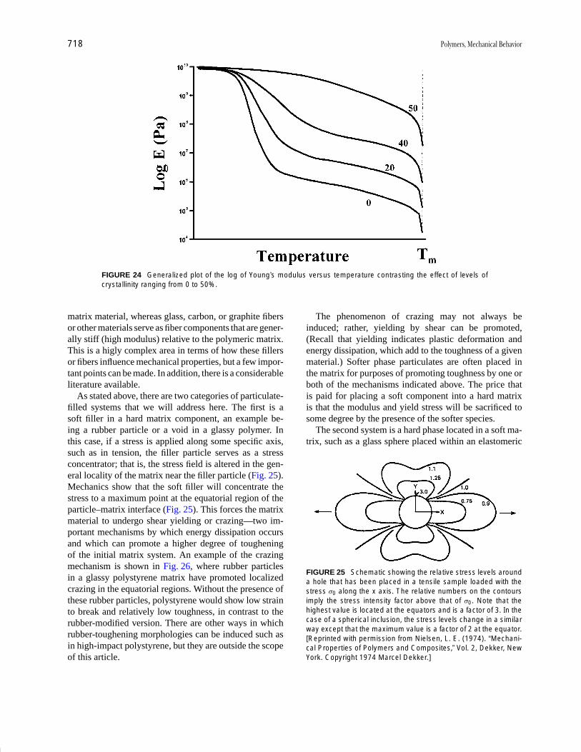
P1: GLM Final Pages
Encyclopedia of Physical Science and Technology EN012c-598 July 26, 2001 15:59
718 Polymers, Mechanical Behavior
FIGURE 24 Generalized plot of the log of Young’s modulus versus temperature contrasting the effect of levels ofcrystallinity ranging from 0 to 50%.
matrix material, whereas glass, carbon, or graphite fibersor other materials serve as fiber components that are gener-ally stiff (high modulus) relative to the polymeric matrix.This is a higly complex area in terms of how these fillersor fibers influence mechanical properties, but a few impor-tant points can be made. In addition, there is a considerableliterature available.
As stated above, there are two categories of particulate-filled systems that we will address here. The first is asoft filler in a hard matrix component, an example be-ing a rubber particle or a void in a glassy polymer. Inthis case, if a stress is applied along some specific axis,such as in tension, the filler particle serves as a stressconcentrator; that is, the stress field is altered in the gen-eral locality of the matrix near the filler particle (Fig. 25).Mechanics show that the soft filler will concentrate thestress to a maximum point at the equatorial region of theparticle–matrix interface (Fig. 25). This forces the matrixmaterial to undergo shear yielding or crazing—two im-portant mechanisms by which energy dissipation occursand which can promote a higher degree of tougheningof the initial matrix system. An example of the crazingmechanism is shown in Fig. 26, where rubber particlesin a glassy polystyrene matrix have promoted localizedcrazing in the equatorial regions. Without the presence ofthese rubber particles, polystyrene would show low strainto break and relatively low toughness, in contrast to therubber-modified version. There are other ways in whichrubber-toughening morphologies can be induced such asin high-impact polystyrene, but they are outside the scopeof this article.
The phenomenon of crazing may not always beinduced; rather, yielding by shear can be promoted,(Recall that yielding indicates plastic deformation andenergy dissipation, which add to the toughness of a givenmaterial.) Softer phase particulates are often placed inthe matrix for purposes of promoting toughness by one orboth of the mechanisms indicated above. The price thatis paid for placing a soft component into a hard matrixis that the modulus and yield stress will be sacrificed tosome degree by the presence of the softer species.
The second system is a hard phase located in a soft ma-trix, such as a glass sphere placed within an elastomeric
FIGURE 25 Schematic showing the relative stress levels arounda hole that has been placed in a tensile sample loaded with thestress σ0 along the x axis. The relative numbers on the contoursimply the stress intensity factor above that of σ0. Note that thehighest value is located at the equators and is a factor of 3. In thecase of a spherical inclusion, the stress levels change in a similarway except that the maximum value is a factor of 2 at the equator.[Reprinted with permission from Nielsen, L. E. (1974). “Mechani-cal Properties of Polymers and Composites,” Vol. 2, Dekker, NewYork. Copyright 1974 Marcel Dekker.]

P1: GLM Final Pages
Encyclopedia of Physical Science and Technology EN012c-598 July 26, 2001 15:59
Polymers, Mechanical Behavior 719
FIGURE 26 Transmission electron micrograph showing crazesinduced in the equatorial regions of rubber particles that are em-bedded in the glassy polystyrene matrix. The arrow labeled witha σ represents the direction of tensile strain. [Reprinted with per-mission from Agarwal, B. D., and Broutman, L. J. (1980). “Analysisand Performance of Fiber Composites,” Wiley, New York. Copy-right 1980 John Wiley and Sons.]
slab. If attention is now placed on the rubber slab compo-nent, there is a desire for this softer material to elongate andto “thin down” around the hard inclusion, thereby placinga hoop stress on the equatorial region of the particle, whichis very different from the system discussed above. In ad-dition, the matrix tends to elongate and pull away fromthe “north” and “south” poles of the particulate, leadingto a possible dewetting or cavitation phenomenon around
FIGURE 27 (a) Photomicrographs showing a glass bead em-bedded in a silicone elastomer that is undergoing elongation asindicated by the percentages. The blackish regions at the “poles”indicate where dewetting or cavitation is occurring, causing a scat-tering of light and a black region to be observed. (b) Surface of theparticle has been treated such that it bonds well with the siliconeelastomer matrix. Less dewetting or cavitation is observed, indi-cating a stronger interface. [Reprinted with permission from Gert,A. N., and Park, B. (1984). J. Mat. Sci. 19, 1950 and 1951.]
the particles. An example of this is illustrated in Fig. 27a,where poor wetting of the particle existed between theelastomer and the glass sphere. In Fig. 27b, a couplingagent was used to bond the particle with the matrix to helpminimize the cavitation process when elongation was un-dertaken. The particle that was bonded showed much lesscavitation at equivalent or higher elongations than did thesystem without the bonding component.
To summarize the two types of particulates discussedabove, it is clear that whether the matrix is hard relative tothe particle, or vice versa, the effect of the dispersed phaseis to modify the stress in the area of that inclusion. Theexact behavior, however, is influenced by the difference inmodulus characteristics of the dispersed phase relative tothat of the matrix.
The effect of fibers versus particulates will not be dis-cussed here. We shall simply point out that because a fiberhas a much higher aspect ratio than more spherical-likeparticles, there is an effect on the stress transfer alongthe fibrous component. This will allow a greater stiffnessto be gained and explains why high-strength compositesoften contain fibrous fillers in contrast to particulates. Afinal point regarding geometrically anisotropic filler par-ticles is that their state of physical orientation will influ-ence the local mechanics of the stress field and hence thisfeature must be considered in any analysis of such filler-containing materials.
X. MOLECULAR ORIENTATIONAND ANISOTROPIC SYSTEMS
The use of polymers for many mechanical applicationsdepends on the fact that previous molecular orientationof molecules has occurred for purposes of influencing theproperties along specific directions. The simplest exam-ple is that of a drawn fiber in which the strength propertiesare important along the fiber axis but generally of littleimportance perpendicular to the same axis. Hence, by ori-entation of the molecules along the stretch direction ordraw axis, the modulus is typically enhanced, as is tensilestrength. Furthermore, the yield point can be eliminatedsince the system will have already gone through an orien-tation step. Generally, maximum or perfect orientation isnot obtained through the drawing operations of bulk sys-tems due to entanglement effects. This can lead to points ofstress concentration and failure long before perfect align-ment of all chains is attained.
There is much interest today in trying to achieve max-imum orientation of polymer chains for purposes of ob-taining ultrahigh-modulus/high-strength systems. Linearpolyethylene has the characteristics to provide an ex-tremely high modulus material of the order of 300 GPa, in

P1: GLM Final Pages
Encyclopedia of Physical Science and Technology EN012c-598 July 26, 2001 15:59
720 Polymers, Mechanical Behavior
TABLE II Comparison of Moduli for Several Different Types of Materialsa
Specific propertiesShear Bulk
Poisson’s Young’s modulus, G modulus, B Density, ρ 106E/ρ 106G/ρMaterial ratio, µ modulus, G (GPa) (Gpa) (g cm3) (m2/sec2) (m2/sec2)
Metals
Cast iron 0.27 90 35 66 7.5 12.0 4.7
Steel (mild) 0.28 220 86 166 7.8 28.0 11.0
Aluminum 0.33 70 26 70 2.7 26.0 9.6
Copper 0.35 120 45 134 8.9 13.5 4.5
Lead 0.43 15 5.3 36 11.0 13.6 4.8
Inorganics
Quartz 0.07 100 47 39 2.65 38.0 17.8
Vitreous silica 0.14 70 31 33 2.20 32.0 14.0
Glass 0.23 60 25 37 2.5 24.0 9.8
Polymers
Polystyrene 0.33 3.2 1.2 3.0 1.05 3.05 1.15
Poly(methyl methacrylate) 0.33 4.15 1.55 4.1 1.17 3.55 1.33
Nylon-6,6 0.33 2.35 0.85 3.3 1.08 2.21 0.79
Polyethylene (low density) 0.45 1.0 0.35 3.33 0.91 1.1 0.385
Ebonite 0.39 2.7 0.97 4.1 1.15 2.35 0.86
Rubber 0.49 0.002 0.0007 0.033 0.91 0.002 0.00075
aAlso included are Poisson’s ratio and density. The last two columns show the specific Young’s and shear moduli.
contrast to 1 to 3 GPa for compression-molded polyethy-lene of the same species (i.e., unoriented). The value ofthe modulus just quoted is actually greater than what ispresently achieved with high-strength/high-modulus liq-uid crystalline polymeric fibers such as poly-p-aromaticamide systems. Again it is apparent that molecular ori-entation can strongly influence mechanical parameters.In addition, an awareness of any previous orientation in-ducement in a system before its measurement may bevery important in deciding how to test the final material.In multiphase or multicomponent systems, the level oforientation is not necessarily equal in each phase (i.e.,crystalline versus amorphous), and hence if orientationis being taken account of, component or phase orienta-tion should be considered rather than necessarily a sys-tem average. Indeed, in oriented semicrystalline systems,typically the crystal phase is much more easily orientedthan that of the remaining amorphous phase. In fact, forfully amorphous systems, the orientation levels obtainedare not particularly high by conventional processes. How-ever, the induced mechanical anisotropy in these systemsis still very considerable and therefore of great practicalimportance.
Due to the fact that orientation has such an impact onmechanical properties, it is one of the principal reasonswhy promoting orientation of the molecular chains is ofhigh importance in achieving high stiffness and other prop-erties (along the stretch direction). Of related interest is
that any property that is determined, when normalized onthe basis of the density of the material, provides whatis known as a specific property such as specific modu-lus. This normalization procedure therefore allows com-parisons between all types of structural materials and anexample of this is illustrated in Table II, which providescomparisons of polymers with inorganics as well as metal-lic systems. As is noted from Table II, which containsthe parameters of Poisson’s ratio, Young’s modulus, shearmodulus, bulk modulus, density, and the specific Young’smodulus and specific shear modulus, the effects of thenormalization procedure bring many of these materialsin line with one another relative to their non-normalizedmoduli values. When orientation in addition is taken intoaccount for polymeric systems, which can drastically alterthe modulus as referred to earlier in this section, the spe-cific moduli can distinctly exceed that of many metallicsor inorganics as is illustrated in Fig. 28. Here one notesthat the material designated as Spectra®, which is a veryhighly oriented and highly crystalline linear polyethylenefiber material, has a much higher specific tensile strengthas well as modulus relative to steel or glass fibers.
XI. MISCELLANEOUS CONSIDERATIONSAND FINAL REMARKS
Many important parameters have not been discussed in thisarticle. For example, the wear characteristics of polymer
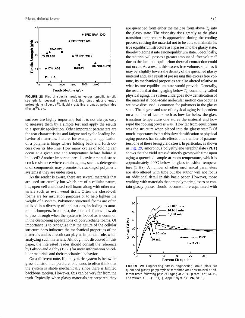
P1: GLM Final Pages
Encyclopedia of Physical Science and Technology EN012c-598 July 26, 2001 15:59
Polymers, Mechanical Behavior 721
FIGURE 28 Plot of specific modulus versus specific tensilestrength for several materials including steel, glass-orientedpolyethylene (Spectra®), liquid crystalline aromatic polyamides(Kevlar®), etc.
surfaces are highly important, but it is not always easyto measure them by a simple test and apply the resultsto a specific application. Other important parameters arethe tear characteristics and fatigue and cyclic loading be-havior of materials. Picture, for example, an applicationof a polymeric hinge where folding back and forth oc-curs over its life-time. How many cycles of folding canoccur at a given rate and temperature before failure isinduced? Another important area is environmental stresscrack resistance where certain agents, such as detergentsor oil components, may promote the cracking of polymericsystems if they are under stress.
As the reader is aware, there are several materials thatare used structurally but which are of a cellular nature,i.e., open-cell and closed-cell foams along with other ma-terials such as even wood itself. Often the closed-cellfoams are for insulation purposes or to help lighten theweight of a system. Polymeric structural foams are oftenutilized in a diversity of applications, including as auto-mobile bumpers. In contrast, the open-cell foams allow airto pass through when the system is loaded as is commonin the cushioning applications of polyurethane foams. Ofimportance is to recognize that the nature of the cellularstructure does influence the mechanical properties of thematerials and as a result can play an important role, whenanalyzing such materials. Although not discussed in thispaper, the interested reader should consult the referenceby Gibson and Ashby (1988) for more information on cel-lular materials and their mechanical behavior.
On a different note, if a polymeric system is below itsglass transition temperature, one tends to often think thatthe system is stable mechanically since there is limitedbackbone motion. However, this can be very far from thetruth. Typically, when glassy materials are prepared, they
are quenched from either the melt or from above Tg intothe glassy state. The viscosity rises greatly as the glasstransition temperature is approached during the coolingprocess causing the material not to be able to maintain itstrue equilibrium structure as it passes into the glassy state,thereby placing it into a nonequilibrium state. Specifically,the material will posses a greater amount of “free volume”due to the fact that equilibrium thermal contraction couldnot occur. As a result, this excess free volume, small as itmay be, slightly lowers the density of the quenched glassymaterial and, as a result of possessing this excess free vol-ume, its mechanical properties are also altered relative towhat its true equilibrium state would provide. Generally,the result is that during aging below Tg, commonly calledphysical aging, the system undergoes slow densification ofthe material if local-scale molecular motion can occur aswe have discussed is common for polymers in the glassystate. The degree and rate of physical aging is dependenton a number of factors such as how far below the glasstransition temperature one stores the material and howrapid the cooling process was. (How far from equilibriumwas the structure when placed into the glassy state?) Ofmuch importance is that this slow densification or physicalaging process has drastic effects on a number of parame-ters, one of these being yield stress. In particular, as shownin Fig. 29, amorphous polyethylene terephthalate (PET)shows that the yield stress distinctly grows with time uponaging a quenched sample at room temperature, which isapproximately 40◦C below its glass transition tempera-ture (1 Hz). A number of other mechanical parametersare also altered with time but the author will not focuson additional detail in this basic paper. However, thoseworking with materials that are polymeric glasses or con-tain glassy phases should become more aquatinted with
FIGURE 29 Engineering stress–engineering strain plots forquenched glassy poly(ethylene terephthalate) determined at dif-ferent times following physical aging at 23◦C. [From Tant, M. R.,and Wilkes, G. L. (1981). J. Appl. Polym. Sci. 26, 2813.]

P1: GLM Final Pages
Encyclopedia of Physical Science and Technology EN012c-598 July 26, 2001 15:59
722 Polymers, Mechanical Behavior
the process of physical aging because it can have drasticeffects on the time-dependent characteristics of those ma-terials. In this respect, the reader may wish to consult thereference by Struick (1978).
An attempt has been made to acquaint the reader withthe philosophy that the author uses in understanding thestructure–property behavior of polymeric systems. Specif-ically, the earthworm analogy and the Deborah numberconcept are believed to be highly useful, and the readershould attempt to apply this thinking when encounteringthe behavior of polymeric materials.
SEE ALSO THE FOLLOWING ARTICLES
COMPOSITE MATERIALS • ELASTICITY, RUBBERLIKE •FRACTURE AND FATIGUE • GLASS • HYDROGEN BOND •MACROMOLECULES, STRUCTURE • PLASTICIZERS • POLY-MER PROCESSING • RUBBER, NATURAL
BIBLIOGRAPHY
Agarwal, B. D., and Broutman, L. J. (1980). “Analysis and Performanceof Fiber Composites,” Wiley, New York.
Aklonis, J. J., and McKnight, W. J. (1983). “Introduction to PolymerViscoelasticity,” 2nd ed., Wiley-Interscience, New York.
Boden, H. E. (1984). Adv. Polym. Technol. 3(4), 383.Boyer, R. F. (1981). Eur. Polym. J. 17, 661.Dealy, J. M. (1982). “Rheometers for Molten Plastics,” Van Nostrand
Reinhold, New York.Gent, A. N., and Park, B. (1984). J. Mater. Sci. 19, 1947.Gibson, L. J., and Ashby, M. E. (1988). “Cellular Solids: Structure and
Properties,” Pergamon Press, New York.Kausch, H. H., and DeVries, K. L. (1975). Int. J. Fract. 11, 727.McCrumb, N. G., Reed, B. E., and Williams, G. (1967). “Anelastic and
Dielectric Effects in Polymeric Solids,” Wiley, New York.Morton, J. R., Johnson, J. F., and Cooper, A. R. (1972). J. Macromol.
Sci. Rev. Macromol. Chem. C8(1), 57.Nielsen, L. E. (1974). “Mechanical Properties of Polymers and Com-
posites,” Vol. 2, Dekker, New York.Nielsen, L. E. (1977). “Polymer Rheology,” Dekker, New York.Randall, R. C., ed. (1984). “NMR and Macromolecules,” Sequence,
Dynamic, and Domain Structure, ACS Symposium Series, Vol.247.
Samuels, R. J. (1974). “Structured Polymer Properties,” Wiley, NewYork.
Struik, L. C. E. (1978). “Physical Aging in Amorphous Polymers andOther Materials,” Elsevier Scientific Publishing Co., New York.
Tant, M. R., and Wilkes, G. L. (1981). J. Appl. Polym. Sci. 26, 2813.Ward, M., ed. (1975). “Structure and Properties of Oriented Polymers,”
Applied Sciences, London.Wetton, R. E., and Stone, M. R. (1983). Proc. Trans. Relax. Polym.
Mater., Melbourne, 1983.Zhang, Y. H., and Carreau, P. J. (1991). J. Appl. Polym. Sci. 42, 1965.
P1: GOJ/GOI/LCC/HAR P2: GOJ Final Pages
Encyclopedia of Physical Science and Technology en012K-946 July 26, 2001 11:14
Polymers, Photoresponsive(in Electronic Applications)
Elsa ReichmanisOmkaram NalamasuFrancis HoulihanBell Laboratories, Lucent Technologies
I. IntroductionII. Polymer Materials RequirementsIII. Historical PerspectiveIV. Chemically Amplified ResistsV. Polymers for Sub-150-nm Imaging Applications
VI. 157-nm Resist DesignVII. Conclusion
GLOSSARY
Chemically amplified resists Resists where the initialexposure to either light or radiation generates a catalystwhich then acts on the surrounding material to initiatea series of reactions that lead to solubility changes inthe matrix.
Contrast The maximum rate change of normalized re-sist thickness per input energy (on a logarithmic scale)achieved upon development of a resist.
Conventional photoresist A photoresist materials that islargely comprised of a substituted novolac resin and adiazonaphthoquinone dissolution inhibitor. Such mate-rials represent the largest fraction of photoresists usedin the production of semiconductor devices today.
Developer A solvent- or aqueous-based liquid mediumthat will selectively remove either the irradiated por-tions of a resist film in the case of positive resists orunexposed areas in the case of negative acting resists.
Dissolution-inhibition resists Resists that are composedof an inherently aqueous-base-soluble matrix resin anda second component that is insoluble in aqueous mediathat renders the matrix insoluble in aqueous solutionas well. Irradiation effects a structural change in dis-solution inhibitor such that dissolution rate of exposedareas is more than that of the matrix resin, thus causinga dissolution promotion.
Etching resistance A measure of how effectively a resistwill withstand the etchants used to transfer images thathave been defined in the resist into the device substrate.
723
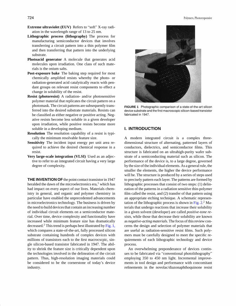
P1: GOJ/GOI/LCC/HAR P2: GOJ Final Pages
Encyclopedia of Physical Science and Technology en012K-946 July 26, 2001 11:14
724 Polymers, Photoresponsive
Extreme ultraviolet (EUV) Refers to “soft” X-ray radi-ation in the wavelength range of 13 to 25 nm.
Lithographic process (lithography) The process formanufacturing semiconductor devices that involvestransferring a circuit pattern into a thin polymer filmand then transferring that pattern into the underlyingsubstrate.
Photoacid generator A molecule that generates acidmolecules upon irradiation. One class of such mate-rials is the onium salts.
Post-exposure bake The baking step required for mostchemically amplified resists whereby the photo- orradiation-generated acid catalytically reacts with pen-dant groups on relevant resist components to effect achange in solubility of the resist.
Resist (photoresist) A radiation- and/or photosensitivepolymer material that replicates the circuit pattern on aphotomask. The circuit patterns are subsequently trans-ferred into the desired substrate materials. Resists canbe classified as either negative or positive acting. Neg-ative resists become less soluble in a given developerupon irradiation, while positive resists become moresoluble in a developing medium.
Resolution The resolution capability of a resist is typi-cally the minimum resolvable feature size.
Sensitivity The incident input energy per unit area re-quired to achieve the desired chemical response in aresist.
Very large-scale integration (VLSI) Used as an adjec-tive to refer to an integrated circuit having a very largedegree of complexity.
THE INVENTION OF the point contact transistor in 1947heralded the dawn of the microelectronics era,1 which hashad impact on every aspect of our lives. Materials chem-istry in general, and organic and polymer chemistry inparticular have enabled the unprecedented advancementsin microelectronics technology. The business is driven bythe need to build devices that contain an increasing numberof individual circuit elements on a semiconductor mate-rial. Over time, device complexity and functionality haveincreased while minimum feature size has dramaticallydecreased.2 This trend is perhaps best illustrated by Fig. 1,which compares a state-of-the-art, fully processed siliconsubstrate containing hundreds of complex devices withmillions of transistors each to the first macrocscpic, sin-gle silicon-based transistor fabricated in 1947. The abil-ity to shrink the feature size is critically dependent uponthe technologies involved in the delineation of the circuitpattern. Thus, high-resolution imaging materials couldbe considered to be the cornerstone of today’s deviceindustry.
FIGURE 1 Photographic comparison of a state-of-the-art silicondevice substrate and the first macroscopic silicon-based transistorfabricated in 1947.
I. INTRODUCTION
A modern integrated circuit is a complex three-dimensional structure of alternating, patterned layers ofconductors, dielectrics, and semiconductor films. Thisstructure is fabricated on an ultrahigh-purity wafer sub-strate of a semiconducting material such as silicon. Theperformance of the device is, to a large degree, governedby the size of the individual elements. As a general rule, thesmaller the elements, the higher the device performancewill be. The structure is produced by a series of steps usedto precisely pattern each layer. The patterns are formed bylithographic processes that consist of two steps: (1) delin-eation of the patterns in a radiation sensitive thin-polymerfilm called the resist, and (2) transfer of that pattern usingan appropriate etching technique. A schematic represen-tation of the lithographic process is shown in Fig. 2.2 Ma-terials that undergo reactions that increase their solubilityin a given solvent (developer) are called positive-tone re-sists, while those that decrease their solubility are knownas negative-acting materials. The focus of this review con-cerns the design and selection of polymer materials thatare useful as radiation-sensitive resist films. Such poly-mers must be carefully designed to meet the specific re-quirements of each lithographic technology and deviceprocess.
An overwhelming preponderance of devices contin-ues to be fabricated via “conventional photolithography”employing 350 to 450 nm light. Incremental improve-ments in tool design and performance with concomitantrefinements in the novolac/diazonaphthoquinone resist

P1: GOJ/GOI/LCC/HAR P2: GOJ Final Pages
Encyclopedia of Physical Science and Technology en012K-946 July 26, 2001 11:14
Polymers, Photoresponsive 725
FIGURE 2 Schematic representation of the lithographic process.
materials chemistry and processing have allowed the con-tinued use of this technology to produce ever-smaller fea-tures (Table I). The cost of introducing a new technology,which includes the costs associated with the developmentand implementation of new hardware and resist materi-als, is a strong driving force pushing photolithography toits absolute resolution limit and extending its commercialviability.3
The technological alternatives to conventional pho-tolithography are largely the same as they were a decadeago: short-wavelength (>250 nm) photolithography, scan-ning or projection electron-beam, X-ray or EUV, or ion-beam lithography.2,4 Unfortunately, conventional photore-sists are not appropriate for use with these new, alternativelithographic technologies. The most notable deficienciesof these materials are their inherent low sensitivity and ab-sorption characteristics that are too high for shorter wave-length exposure to allow uniform imaging through prac-tical resist film thicknesses (about 0.5 to 1 µm). Thus,no matter which technology becomes dominant after pho-tolithography has reached its resolution limit, new resistsand processes will be required.5 The introduction of newresist materials and processes will also require consid-erable lead time to bring them to the performance levelcurrently realized by conventional positive photoresists.
There are significant trade-offs between optimum pro-cess performance and the chemical design of new resists.The ultimate goal of any lithographic technology is to beable to produce the smallest possible features with thelowest cost per level and with wide process latitude. Thebest solution will invariably require compromises, and anunderstanding of materials and process issues is essentialto select the correct compromise.
II. POLYMER MATERIALS REQUIREMENTS
Resist chemistry must be carefully designed to meet thespecific requirements of a given lithographic technology.Although these requirements vary according to the ra-diation source, device process requirements, and expo-sure tool design, the following are ubiquitous: sensitiv-ity, contrast, resolution, etching resistance, purity, andmanufacturability.6 As noted in Table II, each of theseproperties is affected by specific molecular characteristicsof the resin and can be tailored by careful manipulationof polymer structure, molecular properties, and syntheticmethods.7
The polymer resins must:
� Exhibit solubility in solvents that allow the coatingof uniform, defect-free, thin films.
� Be sufficiently thermally stable to withstand thetemperatures and conditions used with standard deviceprocesses.
� Exhibit no flow during pattern transfer of the resistimage into the device substrate.
� Possess a reactive functionality that will facilitate pat-tern differentiation after irradiation.
� For photoexposure, have absorption characteristicsthat will permit uniform imaging through the thickness ofa resist film.
In general, thermally stable (>150◦C), high glass-transition-temperature (Tg > 90◦C) materials with low ab-sorption at the wavelength of interest are desired. If otheradditives are to be employed to effect the desired reac-tion, similar criteria apply. Specifically, they must be non-volatile, be stable up to at least 175◦C, possess a reactivefunctionality that will allow a change in solubility afterirradiation, and have low absorbance. The sections thatfollow outline many of the chemistries that have been ap-plied to the design of resist materials for microlithography.The reader is referred to additional major overviews of thefield for additional information.2,7−10
III. HISTORICAL PERSPECTIVE
A summary of the evolution of lithographic technologiesand the associated materials and devices is presented inTable I.2 The first devices were fabricated on 1-inch sil-icon substrates, were comprised of 256 transistors, andhad minimum features in the range of 15 to 20 µm. Theradiation-induced chemical processes used to effect pat-terning in this era were crosslinking reactions that ledto negative acting resists. As time progressed, alternativehigher resolution, positive-acting material choices became

P1: GOJ/GOI/LCC/HAR P2: GOJ Final Pages
Encyclopedia of Physical Science and Technology en012K-946 July 26, 2001 11:14
726 Polymers, Photoresponsive
TABLE I Evolution of Lithographic and Semiconductor Device Technologies
Lithographic imagingYear technology Resist imaging chemistry Device parameters
1967 Contact printing Cyclized rubber (–) 15–20 µm features; 256 DRAM; 0.2 cm2 device size;1′′ Si substrate
1971 Near contact Cyclized rubber (–) 8–12 µm; 1K DRAM; 0.3 cm2; 2′′ Si substrate
Novolac/diazoquinone (+)
1974 Near contact Novolac/diazoquinone (+) 6 µm; 4K DRAM; 0.4 cm2; 2.5′′ Si substrate
1977 1:1 projection; 360–420 nm Novolac/diazoquinone (+) 4 µm; 16K DRAM; 0.6 cm2; 3′′ Si substrate
1980 Step and repeat; 5–10 × reduction Novolac/diazoquinone (+) <3 µm; 64K DRAM; 0.8 cm2; 4′′ Si substrateoptics; 420–436 nm
1984 Step and repeat; 5 × reduction Novolac/diazoquinone (+) 1.5 µm; 256K DRAM; 1 cm2; 6′′ Si substrateoptics; 436-nm (g-line)
1988 Step and repeat; 5 × reduction Novolac/diazoquinone (+) 0.9 µm; 1.8 cm2
optics; 436-nm (g-line)
1990 Step and repeat; 5 × reduction Novolac/diazoquinone (+) 0.7 µm; 4M DRAM; 1.3 cm2
optics; 365-nm (i-line)
1993 Step and repeat 5 × reduction Novolac/diazoquinone (+) 0.5 µm; 16M DRAM; 1.6 cm2; 8′′ Si substrateoptics; 365-nm (i-line) introduced
1995 Step and repeat; 4–5 × (i-line); Novolac/diazoquinone (+) 0.35 µm; 64MB DRAM; 2 cm2
deep-UV (248 nm)
1998 Step and repeat; deep-UV (248 nm) Chemically amplified 0.25 µm; 256M DRAM; 3 cm2
2001 Step and repeat; deep-UV (248, 193 nm) Chemically amplified 0.18 µm; 1G DRAM; 5 cm2; 8–12′′ Si wafers
2007 Deep-UV (193, 157 nm); EUV (13 nm); Chemically amplified <0.1 µm; 16G DRAM; 8 cm2; 12′′ Si wafersprojection e-Beam; X-ray
available. The following sections outline the “traditional”materials chemistry options.
A. Two-Component Crosslinking Resists
During the early stages of the semiconductor indus-try (1957 to 1970), the minimum size of circuit fea-tures exceeded 5 µm, and the primary resist used dur-
TABLE II Selected Resist Requirements as They Relate to Device Issues and Materials Molecular Characteristics
Lithographic parameter Device issue Molecular characteristic
Absorption Resolution No olefinic or aromatic moiety
Etching stability Process flexibility High levels of structural carbon, low oxygen content
Aqueous base solubility Process flexibility, Base solubilizing groups such as OH, COOH, NH, etc.environmentally friendly
Substrate adhesion Yield Presence of polar moieties
Sensitivity (photospeed) Throughput Catalytic chain length for acidolysis, quantum yield for acidgeneration, acid strength, protective group chemistry
Post-exposure delay and Resolution, process Catalytic chain length for acidolysis, protective groupsubstrate sensitivity flexibility, yield chemistry, acid strength
Outgassing Throughput Protective group and photoacid generator chemistry
Aspect ratio of images Resolution, yield Surface tension effects and mechanical strength of materials
Low metal ion content Yield Synthesis and scale-up methodology
Manufacturability and cost Manufacturing feasibility Synthesis and materials scale-up methodology and lithographicprocess requirements
ing this time consisted of cyclized poly(cis-1,4 isoprene)and an aromatic azide crosslinking compound.9 The bis-aryldiazide, 2,6-bis(4-azidobenzal)-4-methyl cyclohex-anone, effectively initiates crosslinking of the matrix resinupon exposure to near-ultraviolet (UV) light (Fig. 3). Theresolution of this highly sensitive, two-component resistwas limited due to solvent-induced swelling followed bystress relaxation of the developed resist images. Enhanced

P1: GOJ/GOI/LCC/HAR P2: GOJ Final Pages
Encyclopedia of Physical Science and Technology en012K-946 July 26, 2001 11:14
Polymers, Photoresponsive 727
FIGURE 3 Structural representation of the polyisoprenenegative-acting resists.
resolution was achieved by Iwayanagi et al.11,12 Employ-ing an arylazide in conjunction with an aqueous-base-soluble poly(hydroxystyrene) matrix, submicron patternswere defined upon 250-nm exposure. However, the highoptical density of the material at 250 nm afforded undercutresist profiles. Appropriate choice of the crosslinkingagent allows extension of the chemistry of this systeminto the mid-UV range.13
B. Single-Component Crosslinking Resists
Concurrent with the rapid development of electron-beamlithographic tools for both optical mask making anddirect write applications was the commercialization ofsingle-component negative resists. The electron-beam ex-posure requirements of these materials were compati-ble with the dose outputs (∼1 µC/cm2 at 10 kV) ofraster scan machines developed by Bell Laboratories.14
These resists typically contained epoxy, vinyl, and halo-gen functionalities.15,16
Exposure of polymers containing epoxy,17−19 vinyl, andallyl20 affords a radical or cationic species that can reactwith the same (intramolecular crosslink) or neighboring(intramolecular crosslink) polymer chain. This processcontinues via a chain reaction leading to the formationof an insoluble polymer network. Though this reactionsequence affords high resist sensitivity, the propagationof radiation-generated reactive species continues in thevacuum environment of an electron-beam exposure tool.The consequence is that those features that were exposedfirst will have dimensions that are different from those ex-posed last.21 In certain cases, the feature-size differencecan exceed the maximum allowable variation specifiedfor a particular device level, thus these chemistries havelimited usage today.
On the other hand, the halogenated styrene negativeresists crosslink by a radiation-induced reaction that in-volves radicals that recombine and do not propagate.22
Since the reaction sequence does not involve a post-exposure curing reaction and, additionally, the incor-
poration of styrene into the resist improves the dryetching characteristics of the polymers, these materi-als are often favored over aliphatic-based resists. Spe-cific examples of halogenated styrene-based resists arechlorinated23 or chloromethylated24 polystyrene andpoly(chloromethylstyrene).25,26 In addition to being sensi-tive electron-beam resists, the latter also have sensitivity todeep-UV27 and X-ray28 exposure. In one case, the halo-genated material chlorostyrene was copolymerized withglycidyl methacrylate (Fig. 4a) to afford a very sensitivee-beam resist that exhibits little of the curing phenomenatypically observed with epoxy crosslinking reactions.29–31
While the aromatic styrene ring affords improved dry-etching resistance, further improvement in this param-eter can be achieved through incorporation of silicon.For instance, Hatzakis et al.32 showed that polysiloxanepolymers such as poly(vinylmethyl siloxane) readily pro-vide e-beam sensitivity in the 1- to 2-µC/cm2 range. Thesematerials have a high silicon content (>30 wt %), andas such have found use in bilevel lithographic processes(see References 2 and 9 for a definition of bilevel). Otherresists which exhibit acceptable thermal properties andetching resistance for bilevel applications are copolymersof trimethylsilyl-33,34 and trimethylstanylstyrene33 withchlorostyrene (Fig. 4b). Additionally, copolymerizationof trimethylsilylmethyl methacrylate with chloromethyl-styrene yields a viable electron-beam and deep-UV neg-ative resist even through the homopolymer of the silicon-containing methacrylate is a positive-acting material.35 Inthis case, at the exposure dose employed, crosslinking ofthe chloromethylstyrene unites predominates.
FIGURE 4 (a) Structural representation of the negative re-sist, poly(glycidyl methacrylate-co-chlorostyrene), and (b) thecopolymers of chlorostyrene and trimethylsilyl- or trimethyl-stannylstyrene.
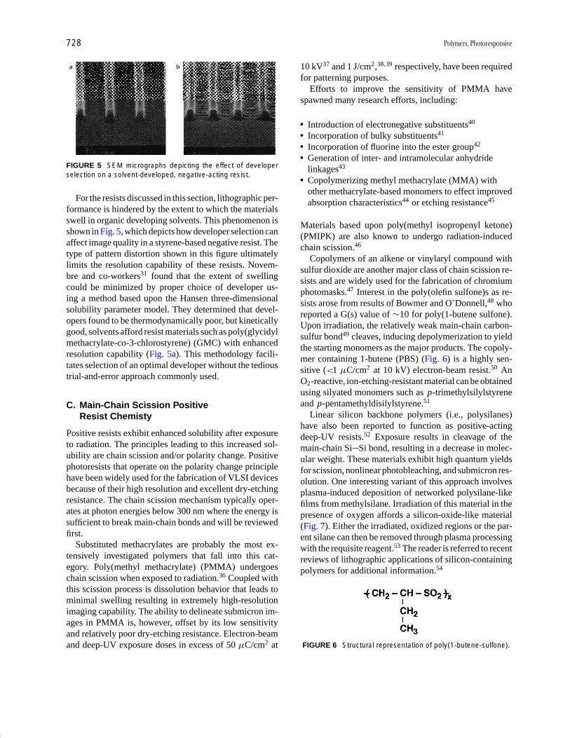
P1: GOJ/GOI/LCC/HAR P2: GOJ Final Pages
Encyclopedia of Physical Science and Technology en012K-946 July 26, 2001 11:14
728 Polymers, Photoresponsive
FIGURE 5 SEM micrographs depicting the effect of developerselection on a solvent-developed, negative-acting resist.
For the resists discussed in this section, lithographic per-formance is hindered by the extent to which the materialsswell in organic developing solvents. This phenomenon isshown in Fig. 5, which depicts how developer selection canaffect image quality in a styrene-based negative resist. Thetype of pattern distortion shown in this figure ultimatelylimits the resolution capability of these resists. Novem-bre and co-workers31 found that the extent of swellingcould be minimized by proper choice of developer us-ing a method based upon the Hansen three-dimensionalsolubility parameter model. They determined that devel-opers found to be thermodynamically poor, but kineticallygood, solvents afford resist materials such as poly(glycidylmethacrylate-co-3-chlorostyrene) (GMC) with enhancedresolution capability (Fig. 5a). This methodology facili-tates selection of an optimal developer without the tedioustrial-and-error approach commonly used.
C. Main-Chain Scission PositiveResist Chemisty
Positive resists exhibit enhanced solubility after exposureto radiation. The principles leading to this increased sol-ubility are chain scission and/or polarity change. Positivephotoresists that operate on the polarity change principlehave been widely used for the fabrication of VLSI devicesbecause of their high resolution and excellent dry-etchingresistance. The chain scission mechanism typically oper-ates at photon energies below 300 nm where the energy issufficient to break main-chain bonds and will be reviewedfirst.
Substituted methacrylates are probably the most ex-tensively investigated polymers that fall into this cat-egory. Poly(methyl methacrylate) (PMMA) undergoeschain scission when exposed to radiation.36 Coupled withthis scission process is dissolution behavior that leads tominimal swelling resulting in extremely high-resolutionimaging capability. The ability to delineate submicron im-ages in PMMA is, however, offset by its low sensitivityand relatively poor dry-etching resistance. Electron-beamand deep-UV exposure doses in excess of 50 µC/cm2 at
10 kV37 and 1 J/cm2,38,39 respectively, have been requiredfor patterning purposes.
Efforts to improve the sensitivity of PMMA havespawned many research efforts, including:
� Introduction of electronegative substituents40
� Incorporation of bulky substituents41
� Incorporation of fluorine into the ester group42
� Generation of inter- and intramolecular anhydridelinkages43
� Copolymerizing methyl methacrylate (MMA) withother methacrylate-based monomers to effect improvedabsorption characteristics44 or etching resistance45
Materials based upon poly(methyl isopropenyl ketone)(PMIPK) are also known to undergo radiation-inducedchain scission.46
Copolymers of an alkene or vinylaryl compound withsulfur dioxide are another major class of chain scission re-sists and are widely used for the fabrication of chromiumphotomasks.47 Interest in the poly(olefin sulfone)s as re-sists arose from results of Bowmer and O’Donnell,48 whoreported a G(s) value of ∼10 for poly(1-butene sulfone).Upon irradiation, the relatively weak main-chain carbon-sulfur bond49 cleaves, inducing depolymerization to yieldthe starting monomers as the major products. The copoly-mer containing 1-butene (PBS) (Fig. 6) is a highly sen-sitive (<1 µC/cm2 at 10 kV) electron-beam resist.50 AnO2-reactive, ion-etching-resistant material can be obtainedusing silyated monomers such as p-trimethylsilylstyreneand p-pentamethyldisilylstyrene.51
Linear silicon backbone polymers (i.e., polysilanes)have also been reported to function as positive-actingdeep-UV resists.52 Exposure results in cleavage of themain-chain Si Si bond, resulting in a decrease in molec-ular weight. These materials exhibit high quantum yieldsfor scission, nonlinear photobleaching, and submicron res-olution. One interesting variant of this approach involvesplasma-induced deposition of networked polysilane-likefilms from methylsilane. Irradiation of this material in thepresence of oxygen affords a silicon-oxide-like material(Fig. 7). Either the irradiated, oxidized regions or the par-ent silane can then be removed through plasma processingwith the requisite reagent.53 The reader is referred to recentreviews of lithographic applications of silicon-containingpolymers for additional information.54
FIGURE 6 Structural representation of poly(1-butene-sulfone).
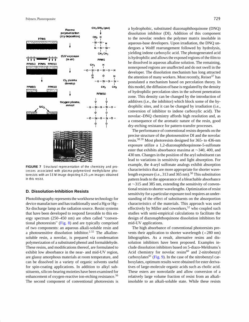
P1: GOJ/GOI/LCC/HAR P2: GOJ Final Pages
Encyclopedia of Physical Science and Technology en012K-946 July 26, 2001 11:14
Polymers, Photoresponsive 729
FIGURE 7 Structural representation of the chemistry and pro-cesses associated with plasma-polymerized methylsilane pho-toresists with an SEM image depicting 0.25-µm images obtainedin this resist.
D. Dissolution-Inhibition Resists
Photolithography represents the workhorse technology fordevice manufacture and has traditionally used a Hg or Hg–Xe discharge lamp as the radiation source. Resist systemsthat have been developed to respond favorable to this en-ergy spectrum (250–450 nm) are often called “conven-tional photoresists” (Fig. 8) and are typically comprisedof two components: an aqueous alkali-soluble resin anda photosensitive dissolution inhibitor.2,55 The alkaline-soluble resin, a novolac, is prepared via condensationpolymerization of a substituted phenol and formaldehyde.These resins, and modifications thereof, are formulated toexhibit low absorbance in the near- and mid-UV region,are glassy amorphous materials at room temperature, andcan be dissolved in a variety of organic solvents usefulfor spin-coating applications. In addition to alkyl sub-stituents, silicon-bearing moieties have been examined forenhancement of oxygen-reactive ion-etching resistance.56
The second component of conventional photoresists is
a hydrophobic, substituted diazonaphthoquinone (DNQ)dissolution inhibitor (DI). Addition of this componentto the novolac renders the polymer matrix insoluble inaqueous-base developers. Upon irradiation, the DNQ un-dergoes a Wolff rearrangement followed by hydrolysis,yielding indene carboxylic acid. The photogenerated acidis hydrophilic and allows the exposed regions of the film tobe dissolved in aqueous alkaline solution. The remaining,nonexposed regions are unaffected and do not swell in thedeveloper. The dissolution mechanism has long attractedthe attention of many workers. Most recently, Reiser57 haspostulated a mechanism based on percolation theory. Inthis model, the diffusion of base is regulated by the densityof hydrophilic percolation sites in the solvent penetrationzone. This density can be changed by the introduction ofadditives (i.e., the inhibitor) which block some of the hy-drophilic sites, and it can be changed by irradiation (i.e.,conversion of inhibitor to indene carboxylic acid). Thenovolac–DNQ chemistry affords high resolution and, asa consequence of the aromatic nature of the resin, gooddry-etching resistance for pattern-transfer processes.
The performance of conventional resists depends on theprecise structure of the photosensitive DI and the novolacresin.58,59 Most photoresists designed for 365- to 436-nmexposure utilize a 1,2-diazonaphthoquinone-5-sulfonateester that exhibits absorbance maxima at ∼340, 400, and430 nm. Changes in the position of the aryl substituent canlead to variations in sensitivity and light absorption. Forexample, the 4-aryl sulfonate analogs exhibit absorptioncharacteristics that are more appropriate for shorter wave-length exposure (i.e., 313 and 365 nm).58 This substitutionpattern leads to the appearance of a bleachable absorbanceat ∼315 and 385 nm, extending the sensitivity of conven-tional resists to shorter wavelengths. Optimization of resistsensitivity for a particular exposure tool requires an under-standing of the effect of substituents on the absorportioncharacteristics of the materials. This approach was usedeffectively by Miller and coworkers,52 who coupled suchstudies with semi-empirical calculations to facilitate thedesign of diazonaphthoquinone dissolution inhibitors formid-UV applications.
The high absorbance of conventional photoresists pre-vents their application to shorter wavelength (<280 nm)lithographies. As a result, alternative resins and dis-solution inhibitors have been proposed. Examples in-clude dissolution inhibitors based on 5-diazo-Meldrums’sAcid chemistry for novolac resins60 and 2-nitrobenzylcarboxylates61 (Fig. 9). In the case of the nitrobenzyl car-boxylates, optimum results were obtained for ester deriva-tives of large-molecule organic acids such as cholic acid.These esters are nonvolatile and allow conversion of arelatively large volume fraction of resist from an alkali-insoluble to an alkali-soluble state. While these resists

P1: GOJ/GOI/LCC/HAR P2: GOJ Final Pages
Encyclopedia of Physical Science and Technology en012K-946 July 26, 2001 11:14
730 Polymers, Photoresponsive
FIGURE 8 Schematic representation of conventional, diazonaphthoquinone–novolac, positive-resist chemistry.
exhibit high sensitivity and contrast and are capable ofsubmicron resolution, their aliphatic nature provides onlymarginal dry-etching resistance.62 Improvements in thetransparency at sub-250-nm wavelengths of the matrixresin used in dissolution inhibition resists while maintain-ing the good dry-etching characteristics can be obtainedby replacing the novolac with poly(4-hydroxystyrene)(PHS) and its substituted analogs.63 Alternatively, alicylicmethacrylates have been used to develop etching-resistant193-nm resist materials.64
Conventional positive photoresists based on novolac–DNQ chemistry have application not only to photolithog-raphy, but also to electron-beam and X-ray lithography.65
One drawback to their use however, is poor sensitivity.The use of polymeric dissolution inhibitors in novolac
FIGURE 9 Structural representation of (a) Meldrum’s Acid and (b) o -nitrobenzyl ester dissolution inhibitor chemistry.
resins has been shown to overcome this issue and produceelectron-beam sensitive-positive resist materials. Bowdenet al.66 have shown that a two-component system con-sisting of a novolac and a poly(olefin sulfone) as the dis-solution inhibitor can generate a resist having electron-beam sensitivities in the 3- to 5-µC/cm2 range at 20 kV.The specific sulfone is poly(2-methyl-1-pentene sulfone)(PMPS) which, when formulated with a novolac resin,renders the novolac insoluble in alkaline media. Exposureto electrons results in spontaneous depolymerization ofPMPS to its volatile monomers. The dissolution inhibitoris thus effectively “vaporized,” thereby allowing dissolu-tion of the remaining aqueous base-soluble novolac resin(Fig. 10).67 Similar materials have been reported by otherworkers.68

P1: GOJ/GOI/LCC/HAR P2: GOJ Final Pages
Encyclopedia of Physical Science and Technology en012K-946 July 26, 2001 11:14
Polymers, Photoresponsive 731
FIGURE 10 The chemistry and imaging characteristics of anovolac–poly(methyl-2-pentene sulfone) electron-beam resist;the SEM image depicts nominal 0.25-µm line/space patterns de-veloped in aqueous tetramethyl ammonium hydroxide.
E. Image Reversal Chemistry
Knowledge that carboxylic acids undergo base-catalyzeddecarboxylation led a number of groups to explore thepossibility of creating negative tone images in conven-tional positive photoresist.69 For instance, addition ofsmall amounts of base additives such as monazoline,imidazole, or triethanolamine to diazoquinone novolacresists, followed by exposure, post-exposure baking, andfinally development in aqueous base generates high-quality negative-tone images. The chemistry and pro-cesses associated with this system are shown in Fig. 11.Effectively, thermally induced, base-catalyzed decarboxy-lation of the indene carboxylic acid destroys the aqueous-base solubility of the exposed resist. Subsequent floodexposure renders the previously masked regions solublein aqueous base, allowing generation of negative tone pat-
FIGURE 11 The chemistry and process sequence for a conven-tional diazonaphthoquinone–novolac photoresist used in an “im-age reversal” mode.
terns. Depending on the precise process conditions that areemployed, the final flood exposure step may be unneces-sary. Also, it is not always necessary to add base to theresist prior to exposure. Alternate image reversal processeshave been developed involving treatment of exposed pho-toresist with a gaseous amine in a vacuum environment.70
IV. CHEMICALLY AMPLIFIED RESISTS
As device feature sizes approached 0.25 µm and the indus-try moved towards using 248 as the exposing wavelengthfor advanced lithographic applications, the materials com-munity saw the first truly revolutionary change in resistmaterials chemistry to be adopted (Table I). Conventionalresists are fundamentally too absorbant to allow uniformimaging through the thickness of the film. Additionally,the available light at the exposure plane of commercial,248-nm exposure tools is insufficient to provide for man-ufacturable processes when the quantum efficiency of a re-sist is less than 1.71 This knowledge laid the foundation forthe breakthrough that ultimately led to the adoption of 248-nm lithography as the technology of choice for advanceddevice fabrication: the announcement of what has beentermed the “chemically amplified” resist mechanism.72,73
A. Deprotection Chemistry
The pioneering work relating to the development ofchemically amplified resists based on deprotection mech-anisms was carried out by Ito et al.72 These initialstudies dealt with the catalytic deprotection of poly(4-tert-butoxycarbonyloxystyrene) (PTBS) in which the ther-mally stable, acid-labile tert-butoxycarbonyl group is usedto mask the hydroxyl functionality of poly(vinylphenol).As shown in Fig. 12, irradiation of PTBS films containingsmall amounts of an onium salt such as diphenyliodo-nium hexafluoroantimonate with UV light liberates anacid species that, upon subsequent baking, catalyzescleavage of the protecting group to generate poly(p-hydroxystyrene). Loss of the tert-butoxycarbonyl groupresults in a large polarity change in the exposed areasof the film. While the substituted phenol polymer is anonpolar material soluble in nonpolar lipophilic solvents,poly(vinylphenol) is soluble in polar organic solvents andaqueous base. These resists have been used successfullyin the manufacture of integrated circuit devices.74
Alternative resins have been investigated for chemicallyamplified resist applications. The parent polymer is typ-ically an aqueous-base-soluble, high Tg resin. Examplesinclude poly(hydroxystryene),74 poly(vinyl benzoate),75
poly(methacrylic acid),76 N -blocked maleimide-styreneresins,77 poly(hydroxyphenyl methacrylate),78 and

P1: GOJ/GOI/LCC/HAR P2: GOJ Final Pages
Encyclopedia of Physical Science and Technology en012K-946 July 26, 2001 11:14
732 Polymers, Photoresponsive
FIGURE 12 Structural representation of the chemistry and process associated with the first positive-acting,chemically amplified resist based on poly(t-butoxy-carbonyloxystyrene) matrix resin chemistry.
poly(4-t-butoxycarbonyloxystyrene-sulfone).79 An in-teresting feature of the styrene sulfone copolymer isits propensity to undergo radiation-induced C S bondscission to generate either sulfinic or sulfonic acidend groups that subsequently induce the deprotectionreaction.80 Thus, additional acid-generating componentsare unnecessary in this case.
A wide range of protective group chemistries havebeen demonstrated to be applicable as well. Examplesof thermally stable yet acid labile substituents that havebeen employed include tert-butyl,81 tetrahydropyranyl,dihydropyranyl,82 and α-α-dimethylbenzyl.83 Hydrolyz-able groups such as trimethylsilyl84 and various acetalsand ketals85 have also been employed. Issues related to ac-etal chemistry include a decrease in the linewidth of unir-radiated patterns with increasing delay intervals.86 Thisphenomenon arises from acid migration at room tempera-ture and may be alleviated through the use of bulky acidsand/or organic base additives.
The concept of acid-catalyzed deprotection may also beapplied to resist formulations utilizing a small moleculeacting as a dissolution inhibitor for an aqueous alkali-soluble resin. This approach possesses a key advantage,namely reduced shrinkage. By using a small moleculedissolution inhibitor, the content of the volatile, acid-cleavable group can be minimized, thus increasing thethermal stability of developed images. Materials that mayeffectively be used in dissolution inhibitor processes in-clude carbonates or ethers of phenols,82,87 esters of car-boxylic acids,88 acetals,89 or orthocarboxylic acid esters.89
In one example, the t-butyl ester of cholic acid is used
as a dissolution inhibitor for a phenol-formaldehyde ma-trix resin.88 Alternatively, a 193-nm resist has been devel-oped using a substituted methacrylate resin in connectionwith a cholate-based inhibitor.63 When formulated withan acid generator, irradiation affords a strong acid, whichupon mild heating liberates cholic acid. The irradiatedregions may then be removed by dissolution in aqueousbase. Workers at Fuji Film have applied their knowledgeof traditional novolac–DNQ dissolution inhibitor chem-istry to the design of improved inhibitors for deep-UVapplications.90 Notably, hydrophobicity, molecular size,and dispersity of the acid-cleavable groups were influen-tial in defining performance. The dissolution inhibitor mayalso be combined with the acid generator functions into asingle chemically amplified resist additive.91
B. Depolymerization Chemistry
Chemically amplified resists that act through a polymerdepolymerization mechanism can be broadly divided intotwo classes: those that act through a thermodynamicallyinduced depolymerization mechanism, and those requir-ing catalytic cleavage of a polymer backbone. The formerprocess depends upon the use of low-ceiling-temperaturepolymers that have been stabilized by suitable end cap-ping. Introduction of a photocleavable moiety either at theend-cap or along the polymer backbone may then allowdepolymerization to take place after irradiation and mildheating. A variant of this approach utilizes an end-capor polymer chain that may be cleaved by photogeneratedacid.75,92 An example is presented in Fig. 13.

P1: GOJ/GOI/LCC/HAR P2: GOJ Final Pages
Encyclopedia of Physical Science and Technology en012K-946 July 26, 2001 11:14
Polymers, Photoresponsive 733
FIGURE 13 Structural representation of the polyphthalaldehydeacid-induced depolymerization mechanism.
C. Crosslinking Mechanisms
Chemical amplification through acid catalyzed crosslink-ing for negative-working resist applications has beenachieved through various mechanisms. These includecationic polymerization, condensation polymerization,electrophilic aromatic substitution, and acid catalyzed re-arrangement. The acid species may be generated from avariety of materials.93
1. Cationic Polymerization Mechanisms
The first chemically amplified resist systems to be de-veloped were those based on the cationic polymerizationof epoxy materials.73,94 In general, the resolution of sub-0.5-µm features in resists based on this mechanism isdifficult due to distortion resulting from solvent-inducedswelling of the irradiated regions. Utilizing aqueousbase soluble materials such as poly(hydroxystyrene-dicyclopentyloxy methacrylate), Allen95 was able to cir-cumvent the issue of swelling to develop a highly sensitive,aqueous-base-soluble i-line and e-beam resist.
2. Condensation Polymerization Mechanisms
Condensation polymerization mechanisms are probablythe most prevalent in the design of chemically amplifiednegative resists. These systems utilize a polymer resin withreactive site(s) (also called a binder) for crosslinking re-actions (e.g., a polymer containing a hydroxy funcation-ality), a radiation-sensitive acid generator, and an acid-activated crosslinking agent.96 Figure 14 depicts some ofthe alternative structures for the above components. Thephotogenerated acid catalyzes the reaction between theresin and crosslinking agent to afford a highly crosslinked
FIGURE 14 Structural representation of representative com-ponents that may be employed in negative-acting, chemi-cally amplified resists that undergo acid-catalyzed condensationpolymerization.
polymer network that is significantly less soluble thanthe unreacted polymer resin. A post-exposure bake stepprior to development is required to complete the con-densation reaction as well as to amplify the crosslinkingyield to enhance sensitivity and improve image contrast.Sub-0.5-µm features could be resolved with deep-UV97
and electron-beam98 radiation with wide process latitudeand high sensitivity using this chemistry. Figure 15 de-picts 0.5-µm images obtained in such a material upon248-nm UV exposure. Very sensitive X-ray and e-beamresist formulations based on similar chemistry using
FIGURE 15 SEM images depicting 0.5-µm line/space imagesobtained in a negative-acting, chemically amplified resist basedupon selected components shown in Fig. 15. [Courtesy of TheShipley Co.]

P1: GOJ/GOI/LCC/HAR P2: GOJ Final Pages
Encyclopedia of Physical Science and Technology en012K-946 July 26, 2001 11:14
734 Polymers, Photoresponsive
melamine and benzyl alcohol derivatives as crosslink-ing agents, formulated with onium salt photoacid gener-ators in novolac or poly(hydroxystyrene) binders, haveshown 0.2-µm line space resolution.96 Other additivesthat undergo acid-induced condensation include com-pounds such as diphenylsilanediol,99 polysiloxanes,100
and diphenylcarbinol.101
3. Electrophilic Aromatic SubstitutionMechanisms
Photo-induced crosslinking can be achieved in styrenepolymers that are susceptible to electrophilic aromaticsubstitution by addition of latent electrophile (i.e., a car-bocation precursor) and a photoacid generator.102 Thephotogenerated acid reacts with the latent electrophileduring a post-exposure bake step to generate a reactivecarbocation that then reacts with an aromatic moiety inthe matrix affording a crosslinked network. The latentelectrophile may be either an additive or a monomer thatis copolymerized into the polymer binder. Examples of la-tent electrophiles include dibenzylacetate and copolymersof acetyloxymethylstyrene102 and 1,3-dioxlane-blockedbenzaldehyde.103
V. POLYMERS FOR SUB-150-NMIMAGING APPLICATIONS
The initial focus for designing 193-nm resists centeredon derivatized acrylate and methacrylate copolymers. Byand large, these polymers are effectively transparent at193 nm and exhibit excellent resolution, but lack plasma-etching resistance and other requisite materials propertiesfor lithographic performance. For instance, the first exam-ple of a high-speed, 193-nm acrylate resist was demon-strated in a collaboration between MIT and IBM. Thismaterial consisted of a methacrylate terpolymer contain-ing acidolytically labile t-butylmethacrylate repeat unitsformulated with a diphenyliodonium triflate onium saltPAG.104 Thus, the fundamental design challenge that hasemerged appears to be the necessary trade-off betweenplasma-etching resistance and requisite materials prop-erties for lithographic performance. On the whole, high-carbon-content copolymers functionalized with pendantalicyclic moieties possess adequate etching resistance buttend to be brittle, display poor adhesion, and have sub-optimal imaging characteristics due to poor aqueous basesolubility. Decreased alicyclic carbon content results inimproved lithographic performance at the cost of etch-ing resistance. Examples of substituents that have beenemployed include menthyl,105 adamantyl,106 isobornyl,107
and tricyclodecyl.108
Recent approaches for addressing this fundamental de-sign challenge include: (1) careful tailoring of polymerproperties to maximize lithographic performance withminimal sacrifice in etching performance, and (2) develop-ment of three-component systems in which high-carbon-content alicyclic additives not only serve as dissolutioninhibitors but also enhance the resistance of the matrix asa whole to plasma environments.
A. Alicyclic Polymers for 193-nm Imaging
As noted above, the first materials platforms that were ex-amined for the purpose of providing transparent, 193-nm,imagable matrices were based on methacrylate resinchemistry (Fig. 16). While methacrylate-based resist plat-forms are attractive from an economic perspective, theysuffer from the fundamental drawback of possessing a lin-ear, oxygen-rich scaffold whose poor plasma-etching sta-bility can be offset only partially by functionalization withmore stable pendant groups. In a more ideal resist plat-form, greater intrinsic plasma stability might be impartedthrough incorporation of alicyclic, etching-resistant moi-eties directly into the polymer backbone. In addition, min-imizing oxygen content by designing oxygenated func-tionalities to play only necessary imaging, adhesion, andsolubilizing roles would be beneficial. Alternative routesto achieve the goal of an “all alicyclic backbone” areshown in Fig. 17 for the alicyclic alkene, norbornene.These routes are ring-opening metathesis polymerization(ROMP),109 metal-catalyzed vinyl polymerization,110 andradical-promoted vinyl polymerization.111 Over the years,several groups have taken such all-alicyclic approachestowards 193-nm resins.112
FIGURE 16 Examples of alicyclic esters of acrylate resins andselected dissolution inhibitors that have been examined in 193-nmlithographic applications.
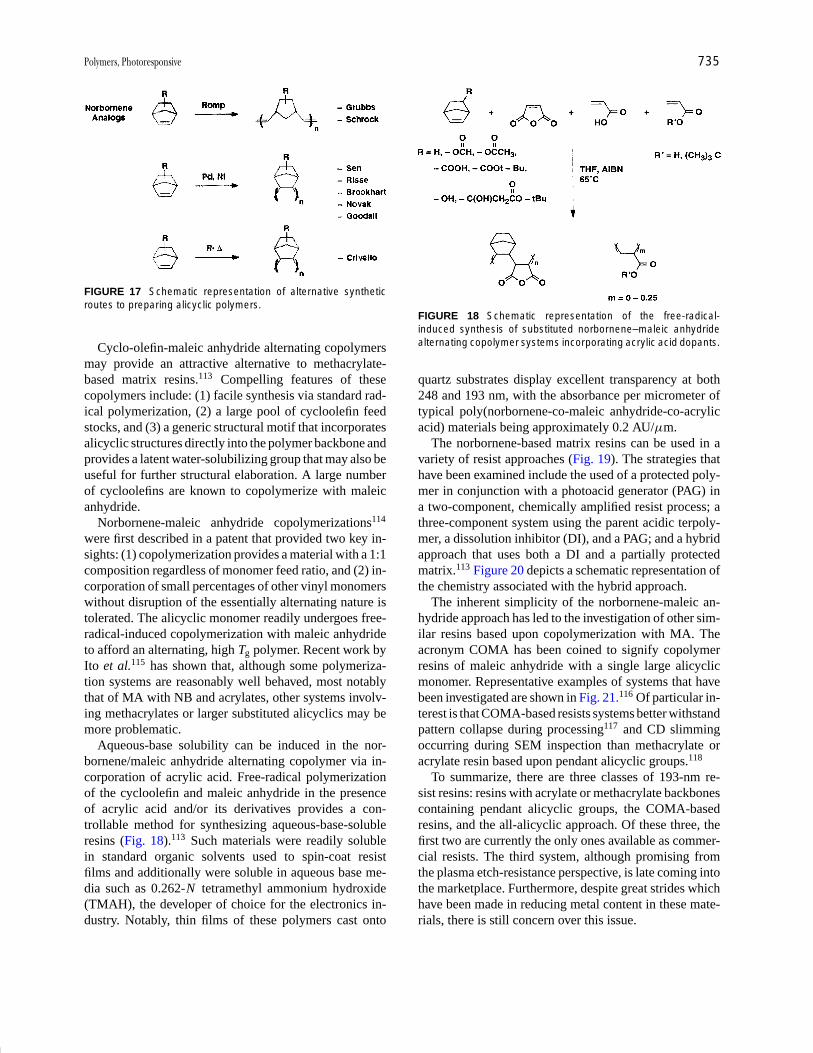
P1: GOJ/GOI/LCC/HAR P2: GOJ Final Pages
Encyclopedia of Physical Science and Technology en012K-946 July 26, 2001 11:14
Polymers, Photoresponsive 735
FIGURE 17 Schematic representation of alternative syntheticroutes to preparing alicyclic polymers.
Cyclo-olefin-maleic anhydride alternating copolymersmay provide an attractive alternative to methacrylate-based matrix resins.113 Compelling features of thesecopolymers include: (1) facile synthesis via standard rad-ical polymerization, (2) a large pool of cycloolefin feedstocks, and (3) a generic structural motif that incorporatesalicyclic structures directly into the polymer backbone andprovides a latent water-solubilizing group that may also beuseful for further structural elaboration. A large numberof cycloolefins are known to copolymerize with maleicanhydride.
Norbornene-maleic anhydride copolymerizations114
were first described in a patent that provided two key in-sights: (1) copolymerization provides a material with a 1:1composition regardless of monomer feed ratio, and (2) in-corporation of small percentages of other vinyl monomerswithout disruption of the essentially alternating nature istolerated. The alicyclic monomer readily undergoes free-radical-induced copolymerization with maleic anhydrideto afford an alternating, high Tg polymer. Recent work byIto et al.115 has shown that, although some polymeriza-tion systems are reasonably well behaved, most notablythat of MA with NB and acrylates, other systems involv-ing methacrylates or larger substituted alicyclics may bemore problematic.
Aqueous-base solubility can be induced in the nor-bornene/maleic anhydride alternating copolymer via in-corporation of acrylic acid. Free-radical polymerizationof the cycloolefin and maleic anhydride in the presenceof acrylic acid and/or its derivatives provides a con-trollable method for synthesizing aqueous-base-solubleresins (Fig. 18).113 Such materials were readily solublein standard organic solvents used to spin-coat resistfilms and additionally were soluble in aqueous base me-dia such as 0.262-N tetramethyl ammonium hydroxide(TMAH), the developer of choice for the electronics in-dustry. Notably, thin films of these polymers cast onto
FIGURE 18 Schematic representation of the free-radical-induced synthesis of substituted norbornene–maleic anhydridealternating copolymer systems incorporating acrylic acid dopants.
quartz substrates display excellent transparency at both248 and 193 nm, with the absorbance per micrometer oftypical poly(norbornene-co-maleic anhydride-co-acrylicacid) materials being approximately 0.2 AU/µm.
The norbornene-based matrix resins can be used in avariety of resist approaches (Fig. 19). The strategies thathave been examined include the used of a protected poly-mer in conjunction with a photoacid generator (PAG) ina two-component, chemically amplified resist process; athree-component system using the parent acidic terpoly-mer, a dissolution inhibitor (DI), and a PAG; and a hybridapproach that uses both a DI and a partially protectedmatrix.113 Figure 20 depicts a schematic representation ofthe chemistry associated with the hybrid approach.
The inherent simplicity of the norbornene-maleic an-hydride approach has led to the investigation of other sim-ilar resins based upon copolymerization with MA. Theacronym COMA has been coined to signify copolymerresins of maleic anhydride with a single large alicyclicmonomer. Representative examples of systems that havebeen investigated are shown in Fig. 21.116 Of particular in-terest is that COMA-based resists systems better withstandpattern collapse during processing117 and CD slimmingoccurring during SEM inspection than methacrylate oracrylate resin based upon pendant alicyclic groups.118
To summarize, there are three classes of 193-nm re-sist resins: resins with acrylate or methacrylate backbonescontaining pendant alicyclic groups, the COMA-basedresins, and the all-alicyclic approach. Of these three, thefirst two are currently the only ones available as commer-cial resists. The third system, although promising fromthe plasma etch-resistance perspective, is late coming intothe marketplace. Furthermore, despite great strides whichhave been made in reducing metal content in these mate-rials, there is still concern over this issue.
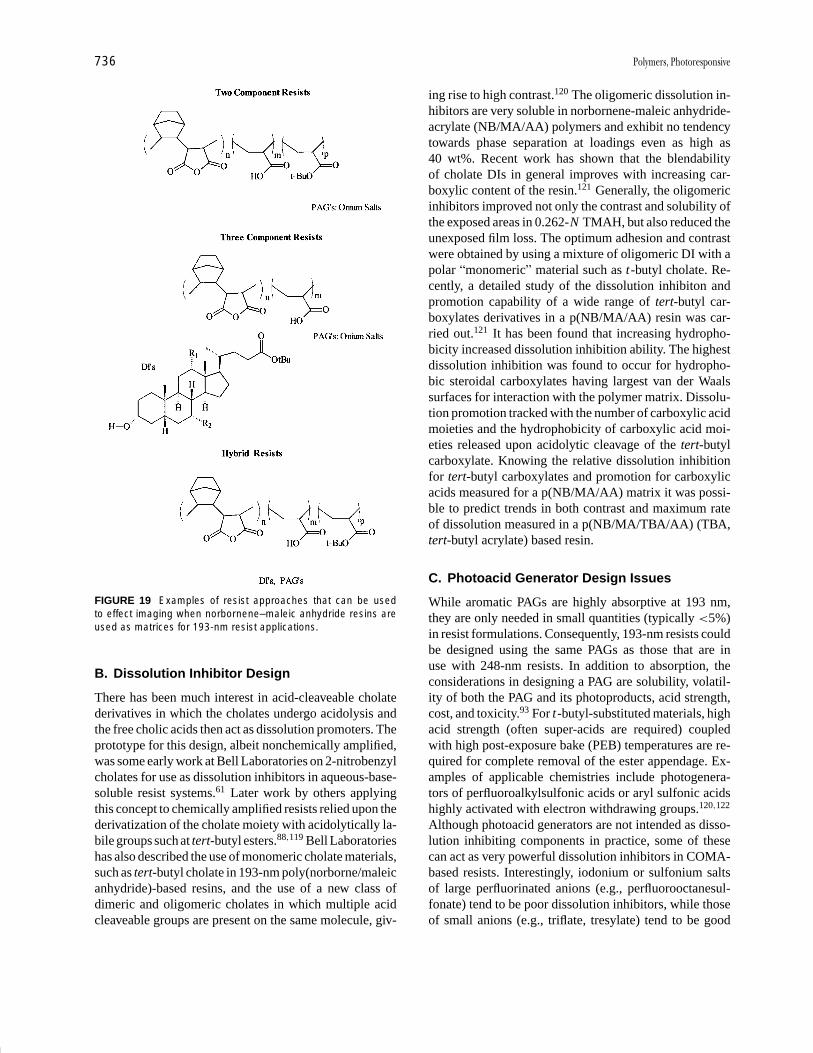
P1: GOJ/GOI/LCC/HAR P2: GOJ Final Pages
Encyclopedia of Physical Science and Technology en012K-946 July 26, 2001 11:14
736 Polymers, Photoresponsive
FIGURE 19 Examples of resist approaches that can be usedto effect imaging when norbornene–maleic anhydride resins areused as matrices for 193-nm resist applications.
B. Dissolution Inhibitor Design
There has been much interest in acid-cleaveable cholatederivatives in which the cholates undergo acidolysis andthe free cholic acids then act as dissolution promoters. Theprototype for this design, albeit nonchemically amplified,was some early work at Bell Laboratories on 2-nitrobenzylcholates for use as dissolution inhibitors in aqueous-base-soluble resist systems.61 Later work by others applyingthis concept to chemically amplified resists relied upon thederivatization of the cholate moiety with acidolytically la-bile groups such at tert-butyl esters.88,119 Bell Laboratorieshas also described the use of monomeric cholate materials,such as tert-butyl cholate in 193-nm poly(norborne/maleicanhydride)-based resins, and the use of a new class ofdimeric and oligomeric cholates in which multiple acidcleaveable groups are present on the same molecule, giv-
ing rise to high contrast.120 The oligomeric dissolution in-hibitors are very soluble in norbornene-maleic anhydride-acrylate (NB/MA/AA) polymers and exhibit no tendencytowards phase separation at loadings even as high as40 wt%. Recent work has shown that the blendabilityof cholate DIs in general improves with increasing car-boxylic content of the resin.121 Generally, the oligomericinhibitors improved not only the contrast and solubility ofthe exposed areas in 0.262-N TMAH, but also reduced theunexposed film loss. The optimum adhesion and contrastwere obtained by using a mixture of oligomeric DI with apolar “monomeric” material such as t-butyl cholate. Re-cently, a detailed study of the dissolution inhibiton andpromotion capability of a wide range of tert-butyl car-boxylates derivatives in a p(NB/MA/AA) resin was car-ried out.121 It has been found that increasing hydropho-bicity increased dissolution inhibition ability. The highestdissolution inhibition was found to occur for hydropho-bic steroidal carboxylates having largest van der Waalssurfaces for interaction with the polymer matrix. Dissolu-tion promotion tracked with the number of carboxylic acidmoieties and the hydrophobicity of carboxylic acid moi-eties released upon acidolytic cleavage of the tert-butylcarboxylate. Knowing the relative dissolution inhibitionfor tert-butyl carboxylates and promotion for carboxylicacids measured for a p(NB/MA/AA) matrix it was possi-ble to predict trends in both contrast and maximum rateof dissolution measured in a p(NB/MA/TBA/AA) (TBA,tert-butyl acrylate) based resin.
C. Photoacid Generator Design Issues
While aromatic PAGs are highly absorptive at 193 nm,they are only needed in small quantities (typically <5%)in resist formulations. Consequently, 193-nm resists couldbe designed using the same PAGs as those that are inuse with 248-nm resists. In addition to absorption, theconsiderations in designing a PAG are solubility, volatil-ity of both the PAG and its photoproducts, acid strength,cost, and toxicity.93 For t-butyl-substituted materials, highacid strength (often super-acids are required) coupledwith high post-exposure bake (PEB) temperatures are re-quired for complete removal of the ester appendage. Ex-amples of applicable chemistries include photogenera-tors of perfluoroalkylsulfonic acids or aryl sulfonic acidshighly activated with electron withdrawing groups.120,122
Although photoacid generators are not intended as disso-lution inhibiting components in practice, some of thesecan act as very powerful dissolution inhibitors in COMA-based resists. Interestingly, iodonium or sulfonium saltsof large perfluorinated anions (e.g., perfluorooctanesul-fonate) tend to be poor dissolution inhibitors, while thoseof small anions (e.g., triflate, tresylate) tend to be good
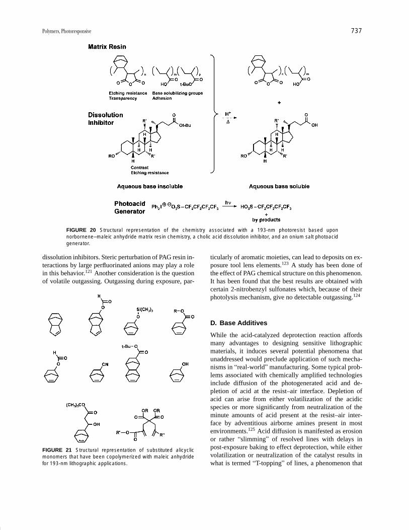
P1: GOJ/GOI/LCC/HAR P2: GOJ Final Pages
Encyclopedia of Physical Science and Technology en012K-946 July 26, 2001 11:14
Polymers, Photoresponsive 737
FIGURE 20 Structural representation of the chemistry associated with a 193-nm photoresist based uponnorbornene–maleic anhydride matrix resin chemistry, a cholic acid dissolution inhibitor, and an onium salt photoacidgenerator.
dissolution inhibitors. Steric perturbation of PAG resin in-teractions by large perfluorinated anions may play a rolein this behavior.121 Another consideration is the questionof volatile outgassing. Outgassing during exposure, par-
FIGURE 21 Structural representation of substituted alicyclicmonomers that have been copolymerized with maleic anhydridefor 193-nm lithographic applications.
ticularly of aromatic moieties, can lead to deposits on ex-posure tool lens elements.123 A study has been done ofthe effect of PAG chemical structure on this phenomenon.It has been found that the best results are obtained withcertain 2-nitrobenzyl sulfonates which, because of theirphotolysis mechanism, give no detectable outgassing.124
D. Base Additives
While the acid-catalyzed deprotection reaction affordsmany advantages to designing sensitive lithographicmaterials, it induces several potential phenomena thatunaddressed would preclude application of such mecha-nisms in “real-world” manufacturing. Some typical prob-lems associated with chemically amplified technologiesinclude diffusion of the photogenerated acid and de-pletion of acid at the resist–air interface. Depletion ofacid can arise from either volatilization of the acidicspecies or more significantly from neutralization of theminute amounts of acid present at the resist–air inter-face by adventitious airborne amines present in mostenvironments.125 Acid diffusion is manifested as erosionor rather “slimming” of resolved lines with delays inpost-exposure baking to effect deprotection, while eithervolatilization or neutralization of the catalyst results inwhat is termed “T-topping” of lines, a phenomenon that
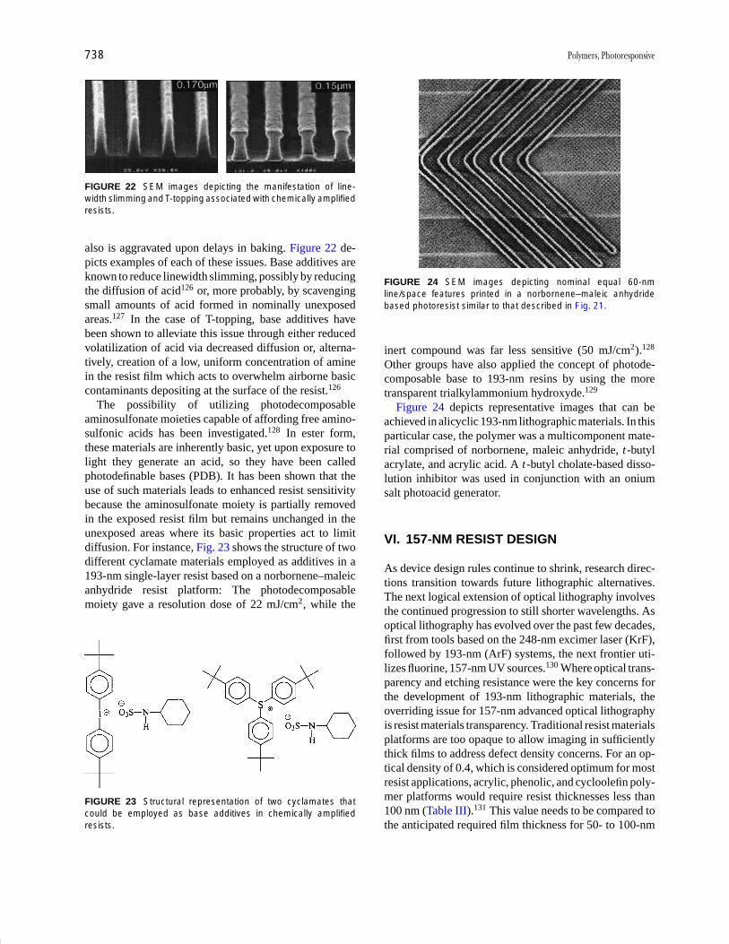
P1: GOJ/GOI/LCC/HAR P2: GOJ Final Pages
Encyclopedia of Physical Science and Technology en012K-946 July 26, 2001 11:14
738 Polymers, Photoresponsive
FIGURE 22 SEM images depicting the manifestation of line-width slimming and T-topping associated with chemically amplifiedresists.
also is aggravated upon delays in baking. Figure 22 de-picts examples of each of these issues. Base additives areknown to reduce linewidth slimming, possibly by reducingthe diffusion of acid126 or, more probably, by scavengingsmall amounts of acid formed in nominally unexposedareas.127 In the case of T-topping, base additives havebeen shown to alleviate this issue through either reducedvolatilization of acid via decreased diffusion or, alterna-tively, creation of a low, uniform concentration of aminein the resist film which acts to overwhelm airborne basiccontaminants depositing at the surface of the resist.126
The possibility of utilizing photodecomposableaminosulfonate moieties capable of affording free amino-sulfonic acids has been investigated.128 In ester form,these materials are inherently basic, yet upon exposure tolight they generate an acid, so they have been calledphotodefinable bases (PDB). It has been shown that theuse of such materials leads to enhanced resist sensitivitybecause the aminosulfonate moiety is partially removedin the exposed resist film but remains unchanged in theunexposed areas where its basic properties act to limitdiffusion. For instance, Fig. 23 shows the structure of twodifferent cyclamate materials employed as additives in a193-nm single-layer resist based on a norbornene–maleicanhydride resist platform: The photodecomposablemoiety gave a resolution dose of 22 mJ/cm2, while the
FIGURE 23 Structural representation of two cyclamates thatcould be employed as base additives in chemically amplifiedresists.
FIGURE 24 SEM images depicting nominal equal 60-nmline/space features printed in a norbornene–maleic anhydridebased photoresist similar to that described in Fig. 21.
inert compound was far less sensitive (50 mJ/cm2).128
Other groups have also applied the concept of photode-composable base to 193-nm resins by using the moretransparent trialkylammonium hydroxyde.129
Figure 24 depicts representative images that can beachieved in alicyclic 193-nm lithographic materials. In thisparticular case, the polymer was a multicomponent mate-rial comprised of norbornene, maleic anhydride, t-butylacrylate, and acrylic acid. A t-butyl cholate-based disso-lution inhibitor was used in conjunction with an oniumsalt photoacid generator.
VI. 157-NM RESIST DESIGN
As device design rules continue to shrink, research direc-tions transition towards future lithographic alternatives.The next logical extension of optical lithography involvesthe continued progression to still shorter wavelengths. Asoptical lithography has evolved over the past few decades,first from tools based on the 248-nm excimer laser (KrF),followed by 193-nm (ArF) systems, the next frontier uti-lizes fluorine, 157-nm UV sources.130 Where optical trans-parency and etching resistance were the key concerns forthe development of 193-nm lithographic materials, theoverriding issue for 157-nm advanced optical lithographyis resist materials transparency. Traditional resist materialsplatforms are too opaque to allow imaging in sufficientlythick films to address defect density concerns. For an op-tical density of 0.4, which is considered optimum for mostresist applications, acrylic, phenolic, and cycloolefin poly-mer platforms would require resist thicknesses less than100 nm (Table III).131 This value needs to be compared tothe anticipated required film thickness for 50- to 100-nm

P1: GOJ/GOI/LCC/HAR P2: GOJ Final Pages
Encyclopedia of Physical Science and Technology en012K-946 July 26, 2001 11:14
Polymers, Photoresponsive 739
TABLE III Resist Thickness Required to Achievean Optical Density of 0.4 for Three Classes of ResistMatrix Polymers23
Thickness to achieveMaterials platform OD = 0.40
Acrylic 46–87 nm
Phenolic 48 nm
Cycloolefin 77 nm
imaging of 200 to ∼400 nm, respectively.131 Thus, av-enues leading to decreased absorbance need to be identi-fied and explored for this application. This said, commer-cially available phenolic-, acrylate-, and cycloolefin-basedresins have been evaluated as “tool testing” resists where“thinness” is not an obstacle. However, even in this appli-cation there is a need to suppress unwanted photochemicalprocesses such as crosslinking or outgassing. The formerleads to undesirable negative-tone behavior in a positiveresist, while the latter can lead to outgassing which candeposit on the objective element of the exposure tool andlead to tool downtime. Such design considerations are cru-cial for all 157-nm systems. Of particular concern is out-gassing of silicon-containing volatiles which can lead toirreversible damage and cannot be cleaned by irradiationin the presence of oxygen as is the case for carbon-basedlens deposits.132
A list of representative polymeric alternatives alongwith their 157-nm absorbance characteristics was reportedby Kunz et al.130 and is presented in Table IV. While hydro-
TABLE IV Survey of 157-nm Absorbance Characteristics ofSelected Polymeric Platforms
Film thicknessAbsorbance (in nm for
Polymer (µm−1) an OD = 0.4)
Si-O Backbone
Poly(hydrosilsequioxane) 0.06 6667
Poly(dimethylsiloxane) 1.61 248
Poly(phenylsiloxane) 2.68 149
Carbon Backbone
Fluorocarbon, 0.70 571100% fluorinated
Hydrofluorocarbon, 1.34 29830% fluorinated
Partially esterified 2.60 154hydrofluorocarbon,28% fluorinated
Poly(vinyl alcohol) 4.16 96
Ethyl cellulose 5.03 80
Poly(methyl methacrylate) 5.69 70
Poly(norbornene) 6.10 66
carbon platforms do not provide sufficient transparency,fluorinated analogs do show potential, as do siloxane-based materials. Etching resistance and adhesion of thefluorinated materials to silicon substrates are concerns thatwill need to be addressed. Interestingly, the Kunz studydemonstrated that the absorbance of many of the standardphotoacid generator materials that have been used for both248- and 193-nm chemically amplified resists have eithersimilar or even lower absorbance at 157 nm than at thelonger wavelengths,130 thus alleviating concerns regard-ing the PAG component. An aspect of materials designthat will be increasingly important at 157 nm is that ofresist outgassing, or rather, the level of volatile speciesevolving from the resist film during exposure. These mayinclude residual solvent, volatile resist components, orby-products generated upon irradiation of the resist film.Clearly, the evolution of volatile species must be kept to aminimum at 157 nm so that these products do not depositonto critical lens surfaces, deleteriously affecting the lenstransmission characteristics.
Several groups are beginning to explore materials al-ternatives for 157 nm applications. Willson133 has uti-lized a “modular approach” in which chemical approachesto instilling necessary functionality into the 157-nm ma-terial is first tested in a model system. In this manner,he and his colleagues have identified the hexafluoroiso-propyl group as an effective aqueous-base-solubilizingmoiety and have shown that it can be protected withacid-labile alkyl acetal protecting groups while main-taining 157-nm transparency. Building from the 193-nmmaterials research that demonstrated the effectiveness ofalicyclic backbone polymers for providing etching resis-tance, Willson133 also showed that substitution of nor-bornene with an electron-withdrawing group such as flu-orine or even a carbonyl group may afford resins withsufficient 157-nm transparency. For instance, the par-tially fluorinated poly(norbornene) shown in Fig. 25ahas an absorbance of only 1.7 AU/micron. Althoughthis absorbance is still too high for practical appli-cations, it demonstrates substantial improvement overnonfluorinated analogs which can have absorbances ashigh as 7 AU/micron, and it represents a promisingstarting point for the design of new materials. Oberet al.134 have reported two design approaches to achiev-ing 157-nm transparency. One system is based upon apoly(trifluoromethylvinyl alcohol-co-vinyl alcohol) resinprotected with acid-labile THP protecting groups, whilein another approach they investigated the introductionof hexafluoropropyl groups onto cyclized polyisoprene(Fig. 25b). The material described to date does not havegood transparency at 157 nm, but it does exhibit a high Tg
(120–170◦C) and good etching resistance. It is anticipatedthat hydrogenation of the olefinic moiety will address the
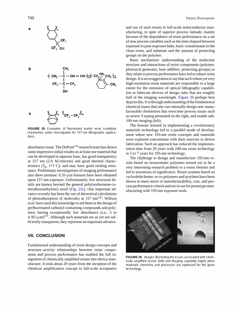
P1: GOJ/GOI/LCC/HAR P2: GOJ Final Pages
Encyclopedia of Physical Science and Technology en012K-946 July 26, 2001 11:14
740 Polymers, Photoresponsive
FIGURE 25 Examples of fluorinated matrix resin candidatechemistries under investigation for 157-nm lithographic applica-tions.
absorbance issue. The DuPont134 research team has shownsome impressive initial results on at least one material thatcan be developed in aqueous base, has good transparencyat 157 nm (2.9 AU/micron) and good thermal charac-teristics (Tg, 171◦C), and may have good etching resis-tance. Preliminary investigations of imaging performancealso show promise: 0.35-µm features have been obtainedupon 157-nm exposure. Unfortunately, few structural de-tails are known beyond the general poly(norbornene-co-tetrafluoroethylene) motif (Fig. 25c). One important ad-vance recently has been the use of theoretical calculationsof photoabsorption of molecules at 157 nm136. Willsonet al. have used this knowledge to aid them in the design ofperfluorinated carbonyl-containing compounds and poly-mers having exceptionally low absorbance (i.e., 3 to4 AU/µm)137. Although such materials are as yet not suf-ficiently transparent, they represent an important advance.
VII. CONCLUSION
Fundamental understanding of resist design concepts andstructure–activity relationships between resist compo-nents and process performance has enabled the full in-tegration of chemically amplified resists into device man-ufacture. It took about 20 years from the inception of thechemical amplification concept to full-scale acceptance
and use of such resists in full-scale semiconductor man-ufacturing, in spite of superior process latitude, mainlybecause of the dependence of resist performance on a setof new process variables such as the time elapsed betweenexposure to post-exposure bake, basic contaminants in theclean room, and substrate and the amount of protectinggroups on the polymer.
Basic mechanistic understanding of the molecularstructure and interactions of resist components (polymer,photoacid generator, base additive, protecting groups) asthey relate to process performance have led to robust resistdesign. It is no exaggeration to say that such robust yet veryhigh-resolution resist materials are responsible to a largeextent for the extension of optical lithography capabili-ties to fabricate devices of design rules that are roughlyhalf of the imaging wavelength. Figure 26 perhaps bestdepicts this. It is through understanding of the fundamentalchemical issues that one can rationally design new manu-facturable chemistries that overcome process issues suchas severe T-typing presented on the right, and enable sub-100-nm imaging (left).
The lessons learned in implementing a revolutionarymaterials technology led to a parallel mode of develop-ment where new 193-nm resist concepts and materialswere explored concomitant with their exercise in devicefabrication. Such an approach has reduced the implemen-tation time from 20 years with 248-nm resist technologyto 5 to 7 years for 193-nm technology.
The challenge to design and manufacture 193-nm re-sists based on nonaromatic polymers turned out to be avery interesting research problem to a resist chemist andled to inventions of significance. Resist systems based oncycloolefin homo- or co-polymers and acrylates have beenshown to meet much of manufacturability, cost, and pro-cess performance criteria and are in use for prototype man-ufacturing with 193-nm exposure tools.
FIGURE 26 Images illustrating the issues associated with chem-ically amplified resists (left) and imaging capability (right) whenmaterials chemistry and processes are optimized for the giventechnology.

P1: GOJ/GOI/LCC/HAR P2: GOJ Final Pages
Encyclopedia of Physical Science and Technology en012K-946 July 26, 2001 11:14
Polymers, Photoresponsive 741
The intense industry interest in 157-nm lithography hascatalyzed activity in designing ultrathin resists that wouldmost probably be based on fluoropolymers and/or siloxanechemistries. Such lithography also poses yet another chal-lenge to the resist community and is the topic of intenseresearch.
SEE ALSO THE FOLLOWING ARTICLES
INTEGRATED CIRCUIT MANUFACTURE • PHOTOCHEM-ISTRY, MOLECULAR • POLYMERS, MECHANICAL BEHAV-IOR • THIN FILM TRANSISTORS
BIBLIOGRAPHY
1. Bardeen, J., and Brattain, W. H. ( 1948). Phys. Rev. 74(2), 230.2. Thompson, L. F., Willson, C. G., and Bowden, M. J. (1994). “Intro-
duction to Microlithography,” ACS Professional Reference Book,Washington, D.C.
3. McCoy, J. H., Lee, W., and Varnell, G. L. (1989). Solid State Tech-nol. 32(3), 87.
4. Takigawa, T. (1992). Photopolymer Sci. Technol. 5(1), 1; DeJule,R. (1998). Semiconductor Int. 21(2), 54; Dejule, R. (1999). 22(3),48; McClay, J. A., and McIntyre, S. L. (1999). Solid State Technol.42(6), 57.
5. Reichmanis, E., and Thompson, L. F. (1989). In “Polymers in Mi-crolithography: Materials and Processes,” ACS Symposium Series412 (E. Reichmanis, S. A. MacDonald, and T. Iwayanagi, eds.),pp. 1–24, ACS, Washington, D.C.
6. Thompson, L. F. (1994). In “Introduction to Microlithography,”pp. 269–375, ACS Professional Reference Book, Washington, D.C.
7. Reichmanis, E., and Thompson, L. F. (1989). Chem. Rev. 89, 1273.8. Moreau, W. M. (1988). “Seimconductor Lithography; Principles,
Practices, and Materials,” Plenum, New York.9. Reiser, A. (1989). “Photoreactive Polymers: The Science and Tech-
nology of Resists,” John Wiley & Sons, New York, pp. 22–65.10. Reichmanis, E., and Neenan, T. X. (1998). In “Chemistry of Ad-
vanced Materials: An Overview” (L. V. Interrante, and M. J.Hampden-Smith, eds.), pp. 99–141, Wiley-VCH, New York.
11. Iwayanagi, T., Kohashi, T., Nonogaki, S., Matsuzawa, T., Douta,K., and Yanazawa, H. (1981). IEEE Trans. Elec. Dev. Ed. 28(11),1305–1310.
12. Nonogaki, S., Hashimoto, H., Iwayanagi, T., and Shiraishi, H.(1985). Proc. SPIE 529, 189.
13. Hoshimoto, H., Iwayanagi, T., Shiraishi, H., and Nonogoaki, S.(1985). “Proc. Regional Technical Conference on Photopolymers,”Mid-Hudson Section SPE, Ellenville, NY, p. 11.
14. Heriott, D. R., Collier, R. J., Alles, D. S., and Stafford, J. W. (1975).IEEE Trans. Electron. Devices ED-22, 385.
15. Thompson, L. F., and Kerwin, R. E. (1976). Ann. Rev. MaterialsSci. (R. A. Huggins, R. H. Bube, and R. W. Roberts, eds.), 6, 267–301.
16. Tagawa, S. (1987). In “Polymers for High Technology: Electronicsand Photonics,” ACS Symposium Series 346 (L. F. Thompson,C. G. Willson, and J. M. Frechet, eds.), pp. 37–45, ACSWashington, D.C.
17. Hirai, T., Hatano, Y., and Nonogaki, S. (1971). J. Electrochem.Soc. 118(4), 669.
18. Feit, E. D., Thompson, L. F., and Heidenreich, R. D. (1973). ACSDiv. Org. Coat. Plast. Chem. Preprint, 383.
19. Taniguchi, Y., Hatano, Y., Shiraishi, H., Horigome, S., Nonogoki,S., and Naraoka, K. (1979). Jpn. J. Appl. Phys. 28, 1143.
20. Tan, Z. C., Petropolous, C. C., and Rauner, F. J. (1981). J. Vac.Sci. Technol. 19(4), 1348.
21. Novembre, A. E., and Bowden, M. J. (1983). Polym. Eng. Sci. 23,977.
22. Tabata, Y., Tagawa, S., and Washio, M. (1984). In “Materialsfor Microlithography” (L. F. Thompson, C. G. Willson, andJ. M. J. Frechet, eds.), p. 161, ACS Sympsoium Series 266, ACS,Washington, D.C.
23. Hartney, M. A., Tarascon, R. G., and Novembre, A. E. (1985). J.Vac. Sci. Technol. B3, 360.
24. Imamura, S. (1979). J. Electrochem. Soc. 126(9), 1268.25. Choong, H. S., and Kahn, F. J. (1981). J. Vac. Sci. Technol. 19(4),
1121.26. Feit, E. D., Thompson, L. F., Wilkins, C. W., Jr., Wurtz, M. E.,
Doerries, E. M., and Stillwagon, L. E. (1979). J. Vac. Sci. Technol.16(6), 1287.
27. Imamura, S., and Sugawara, S. (1982). J. Appl. Phys. 21, 776.28. Yoshioka, N., Suzuki, Y., and Yamazaki, T. (1985). Proc. SPIE
537, 51.29. Thompson, L. F., and Doerries, E. M. (1979). J. Electrochem. Soc.
126(10), 1699.30. Thompson, L. F., Yau, L., and Doerries, E. M. (1979). J.
Electrochem. Soc. 126(10), 1703.31. Novembre, A. E., Masakowski, L. M., and Hartney, M. A. (1986).
Poly. Eng. Sci. 26(6), 1158.32. Hatzakis, M., Paraszczak, J., and Shaw, J. M. (1981). In “Micro-
circuit Eng. 81” (A. Oosenburg, ed.), pp. 386–396, Swiss Fed.Inst. Technol., Lausanne.
33. MacDonald, S. A., Steinman, F., Ito, H., Lee, W.-Y., and Willson,C. G. (1983). Preprints. ACS Div. Polymeric Materials: Sci. Eng.50, 104.
34. Suzuki, M., Saigo, K., Gokan, H., and Ohnishi, Y. (1983). J.Electrochem. Soc. 130, 1962.
35. Novembre, A. E., Jurek, M. J., Kornblit, A., and Reichmanis, E.(1989). Polym. Eng. Sci. 23, 920.
36. Ranby, B., and Rabek, J. F. (1975). “Photodegradation, Photoox-idation and Photostabilization of Polymers,” John Wiley & Sons,New York, pp. 15–159.
37. Hatzakis, M. (1969). J. Electrochem. Soc. 116, 1033.38. Mimura, Y., Ohkubo, T., Takanichi, T., and Sekikawa, K. (1978).
Jpn. Appl. Phys. 17, 541.39. Lin, B. (1975). J. Vac. Sci. Technol. 12, 1317.40. Helbert, J. N., Chen, C. Y., Pittman, C. U., Jr., and Hagnauer, G. L.
(1978). Macromolecules 11, 1104; Lai, J. H., Helbert, J. N., Cook,C. F., Jr., and Pittman, C. U., Jr. (1979). J. Vac. Sci. Technol. 16(6),1992; Helbert, J. N., Wagner, B. E., Caplan, J. P., and Poindexter,E. H. (1975). J. Appl. Poly. Sci. 19, 1201; Chen, C. Y., Pittman, C.U., Jr., and Helbert, J. N. (1980). J. Poly. Sci. Poly Chem. Ed. 18,169.
41. Moreau, W. M. (1982). Proc. SPIE 333, 2.42. Kakuchi, M., Sugawara, S., Murase, K., and Matsuyama, K. (1977).
J. Electrochem. Soc. 224, 1648; Tada, T. (1979). J. Electrochem.Soc. 126, 1829; Tada, T. (1983). J. Electrochem. Soc. 130, 912.
43. Roberts, E. D. (1977). ACS Div. Org. Coat. Plastics Chem.Preprints 37(2), 36; Moreau, W., Merritt, D., Moyer, W., Hatzakis,M., Johnson, D., and Pederson, L. (1979). J. Vac. Sci. Technol.16(6), 1989; Namaste, Y. M. N., Obendorf, S. K., Anderson, C. C.,Krasicky, P. D., Rodriguez, F., and Tiberio, R. (1983). J. Vac. Sci.Technol. B 1(4), 1160.
P1: GOJ/GOI/LCC/HAR P2: GOJ Final Pages
Encyclopedia of Physical Science and Technology en012K-946 July 26, 2001 11:14
742 Polymers, Photoresponsive
44. Reichmanis, E., and Wilkins, C. W., Jr. (1982). In “PolymerMaterials for Electronics Applications,” ACS Symposium Series184 (E. D. Feit, and C. W. Wilkins, Jr., eds.), pp. 29–43, ACS,Washington, D.C.; Hartless, R. L., and Chandross, E. A. (1981).J. Vac. Sci. Technol. 19, 1333.
45. Reichmanis, E., Smolinsky, G., and Wilkins, C. W., Jr. (1984).Solid State Technol. 28(8), 130; Reichmanis, E., and Smolinsky,G. (1984). Proc. SPIE 469, 38; Reichmanis, E., and Smolinsky,G. (1985). J. Electrochem. Soc. 132, 1178.
46. Tsuda, M., Oikawa, S., Nakamura, Y., Nagata, H., Yokota, A.,Nakane, H., Tsumori, T., and Nakane, Y. (1979). Photogr. Sci.Eng. 23, 1290; MacDonald, S. A., Ito, H., Willson, C. G., Moore,J. W., Charapetian, H. M., and Guillet, J. E. (1984). In “Materialsfor Microlithography” (L. F. Thompson, C. G. Willson, andJ. M. J. Frechet, eds.), pp. 179, ACS Symposium Series 266, ACS,Washington, D.C.
47. Brown, J. R., and O’Donnell, J. H. (1970). Macromolecules 3,265; Brown, J. R., and O’Donnell, J. H. (1972). Macromolecules 5,109.
48. Bowmer, T. N., and O’Donnell, J. H. (1981). Radiation Phys.Chem. 17, 177.
49. Bowden, M. J., Thompson, L. F., and Ballantyne, J. P. (1975).J. Vac. Sci. Technol. 126(6), 1294.
50. Bowden, M. J., and Thompson, L. F. (1979). Solid State Technol.22, 72.
51. Gozdz, A. (1987). Solid State Technol. 30(6), 75; Gozdz, A., Ono,H., Ito, S., and Shelbourne, III, J. A. (1991). Proc. SPIE 1446, 200.
52. Hofer, D. C., Miller, R. D., McKean, D. R., Willson, C. G., West,R., and Trefonas, R. T. (1984). In “Materials for Microlithography”(L. F. Thompson, C. G. Willson, J. M. J. Frechet, eds.), p. 283,ACS Sympsoium Series 266, ACS, Washington, D.C.; Miller,R. D., Hofer, D. C., and Willson, C. G. (1984). Proc. SPIE 469,16; Zeigler, J. M., Harrah, L. A., and Johnson, A. W. (1985). Proc.SPIE 539, 166; Kunz, R. R., and Horn, M. W. (1991). “Proceed-ings, Regional Tech. Conf. Photopolymers,” Mid-Hudson Section,SPE, Ellenville, NY, October 28–30, p. 291.
53. Weidman, T. W., and Joshi, A. J. (1992). Appl. Phys. Lett. 62,372; Dabbagh, G., Hutton, R. S., Cirelli, R. A., Reichmanis, E.,Novembre, A. E., and Nalamasu, O. (1998). Proc. SPIE 3333, 334.
54. Reichmanis, E., Novembre, A. E., Nalamasu, O., and Dabbagh,G. (2000). In “Silicon Containing Polymers” (R. G. Jones, W.Ando, and J. Chajnowski, eds.), pp. 743–762, Kluwer Academic,Netherlands.
55. Dammel, R. (1993). In “Diazonaphthoquinone-Based Resists” (D.Shea, ed.), p. 70, SPIE, Optical Engineering Press, Bellingham,WA.
56. Tarascon, R. G., Shugard, A., and Reichmanis, E. (1986). Proc.SPIE 631, 40; Soatome, Y., Gokan, H., Saigo, K., Suzuki, M., andOhnishi, Y. (1985). J. Electrochem. Soc. 132, 909.
57. Yeh, T. F., Reiser, A., Dammel, R. R., Pawlowski, G., andRoeschert, H. (1993). Macromolecules 26, 3862; Shih, Y.-H., Yeh,T. F., Reiser, A., Dammel, R. R., Merrem, H. J., and Pawlowski,G. (1994). Proc. SPIE 2195, 514.
58. Miller, R. D., Willson, C. G., McKean, D. R., Tomkins, T., Clecak,N., Michl, J., and Downgin, J. (1982). “Proc. Reg. Tech. Conf.On Photopolymers,” Mid-Hudson Section SPE, Ellenville, NY,November 8–10, p. 111.
59. Hanabata, M., Furuta, A., and Uemura, Y. (1986). Proc. SPIE 631,76; Hanabata, M., Furuta, A., and Uemura, Y. (1987). Proc. SPIE771, 85; Hanabata, M., Oi, F., and Furuta, A. (1991). Proc. SPIE1446, 132; Templeton, M. K., Szmanda, C. R., and Zampini, A.(1987). Proc. SPIE 777, 136; Trefonas, P., III, Daniels, B. K., andFischer, R. K. (1987). Solid State Technol. 30, 131.
60. Willson, C. G., Miller, R. D., and McKean, D. R. (1987). Proc.SPIE 771, 2.
61. Reichmanis, E., Wilkins, C. W., Jr., and Chandross, E. A. (1981).J. Vac. Sci. Technol. 19(4), 1338.
62. Pederson, L. A. (1982). J. Electrochem. Soc. 129, 205; Gokan,H., Esho, S., and Ohnishi, Y. (1983). J. Electrochem. Soc. 130,154.
63. Pawlowski, G., Sauer, T., Dammel, R., Gordon, D. J., Hinsberg,W., McKean, D., Lindley, C. R., Merrem, H. J., Vicari, R., andWillson, C. G. (1990). Proc. SPIE 1262, 391; Przybilla, K.,Roeschert, H., Spiess, W., Eckes, C., Chatterjee, S., Khanna, D.,Pawlowski, G., and Dammel, R. (1991). Proc. SPIE 1466, 174.
64. Kaimoto, Y., Nozaki, K., Takechi, S., and Abe, N. (1992). Proc.SPIE 1262, 66; Kuna, R. R., Allen, R. D., Hinsberg, W. D.,and Wallraff, G. M. (1993). Proc. SPIE 1925, 167; Abe, N.,Takechi, S., Kaimoto, Y., Takahashi, M., and Nozaki, K. (1995).J. Photopolymer Sci. Technol. 8(4), 637; Allen, R. D., Wan,I. Y., Wallraff, G. M., DiPietro, R. A., and Hofer, D. C. (1995).J. Photopolymer Sci. Technol. 8(4), 623.
65. Shaw, J. M., and Hatzakis, M. (1979). J. Electrochem. Soc. 126,2026; Huber, H. L., Betz, H., Heuberger, A., and Pongrate, S.(1984). Microelectronic Eng. 84, 325; Peters, D. W. (1988). Proc.SPIE 923, 36.
66. Bowden, M. J., Thompson, L. F., Fahrenholtz, S. R., and Doerries,E. M. (1981). J. Electrochem. Soc. 128, 1304.
67. Tarascon, R. G., Frackoviak, J., Reichmanis, E., and Thompson,L. F. (1987). Proc. SPIE 771, 54; Frackoviak, J., Tarascon, R. G.,Vaidya, S., and Reichmanis, E. (1987). 771, 120.
68. Shiraishi, H., Isobe, A., Murai, F., and Nonogaki, S. (1984).In “Polymers in Electronics” (T. Davidson, Ed.), p. 167, ACSSymposium Series 242, ACS, Washington, D.C.; Chang, Y. Y.,Grant, B. D., Pederson, L. A., and Willson, C. G. (1983). U.S.Patent. 4,398,001.
69. Moritz, H. (1895). IEEE Trans. Electron Devices ED-32, 672;Takahashi, Y., Shinozaki, F., and Ikeda, T. (1980). Jpn. KokaiTokyo Koho 88, 8032; MacDonald, S. A., Ito, H., and Willson,C. G. (1983). Microelectronic Eng. 1, 269.
70. Alling, E., and Stauffer, C. (1985). Proc. SPIE 529, 194.71. Willson, C. G., and Bowden, M. J. (1988). In “Electronic and
Photonic Applications of Polymers” (M. J. Bowden, and S. R.Turner, eds.), pp. 75–108, ACS Advances in Chemistry Series218, ACS, Washington, D.C.; Iwayanagi, T., Ueno, T., Nonogaki,S., Ito, H., and Willson, C. G. (1988). In “Electronic and PhotonicApplications of Polymers” (M. J. Bowden and S. R. Turner, eds.),pp. 109–224, ACS Advances in Chemistry Series 218, ACS,Washington, D.C.; Reichmanis, E. Houlihan, F. M., Nalamasu, O.,and Neenan, T. X. (1991). Chem. Mater. 3, 397.
72. Ito, H., and Willson, C. G. (1984). In “Polymers in Electronics”(T. Davidson, ed.), pp. 11–23, ACS Symposium Series 242, ACS,Washington, D. C.; Frechet, J. M. J., Eichler, E., Ito, H., andWillson, C. G. (1990). Polymer 24, 995; Ito, H., Willson, C. G.(1983). Polym. Eng. Sci. 23, 1012; Ito, H., Willson C. G., Frechet,J. M. J., Farrall, M. J., and Eichler, E. (1983). Macromolecules 16,1510.
73. Crivello, J. V. (1984). In “Polymers in Electronics” (T. Davidson,ed.), pp. 3–10, ACS Symposium Series 242, ACS, Washington,D.C.
74. Maltabes, J. G. et al. (1990). Proc. SPIE 1262, 2.75. Ito, H., and Willson, C. G. (1987). Proc. SPIE 771, 24.76. Ito, H., Ueda, M., and Ebina, M. (1989). In “Polymers in
Microlithography” (E. Reichmanis, S. A. MacDonald, and T.Iwayanagi, eds.), p. 57, ACS Symposium Series 412, ACSWashington, D.C.
P1: GOJ/GOI/LCC/HAR P2: GOJ Final Pages
Encyclopedia of Physical Science and Technology en012K-946 July 26, 2001 11:14
Polymers, Photoresponsive 743
77. Osuch, C. E., Brahim, K., Hopf, F. R., McFarland, M. J., MooringA., and Wu, C. J. (1986). Proc. SPIE 631, 68; Turner, S. R.,Ahn, K. D., and Willson, C. G. (1987). In “Polymers for HighTechnology” (M. J. Bowden and S. R. Turner, eds.), pp. 200–210,ACS Symposium Series 346, ACS, Washington, D.C.
78. Przybilla, K. J., Dammel, R., Pawlowski, G., Roschert, J., andSpiess, W. (1991). “Proc. Regional Technical Conf. on Photopoly-mers,” Mid-Hudson Section SPE, Ellenville, NY, October 28–30,p. 131.
79. Kanga, R. S., Kometani, J. M., Reichmanis, E., Hanson, J. E.,Nalamasu, O., Thompson, L. F., Heffner, S. A., and Tai, W. W.(1991). Chem. Mater. 3, 660; Houlihan, F. M., Reichmanis, E.,Thompson, L. F., and Tarascon, R. G. (1989). In “Polymers inMicrolithography” (E. Reichmanis, S. A. MacDonald, and T.Iwayanagi, eds.), pp. 39-56, ACS Symposium Series 412, ACS,Washington, D.C.
80. Novembre, A. E., Tai, W. W., Kometani, J. M., Hanson, J. E.,Nalamasu, O., Taylor, G. N., Reichmanis, E., and Thompson, L. F.(1992). Chem. Mater. 4, 278.
81. Crivello, J. V. (1989). J. Electrochem. Soc. 189, 1453.82. Hayashi, N., Hesp, S. M. A., Ueno, T., Toriumi, M., Iwayanagi,
T., and Nonogaki, S. (1989). Proc. Polym. Mat. Sci. Eng. 61, 417;Frechet, J. M. J., Kallman, N., Kryczka, B., Eichler, E., Houlihan,F. M., and Willson, C. G. (1988). Polymer Bull. 20, 427; Frechet,J. M. J., Eichler, W., Gauthier, S., Krychzka, B., and Willson,C. G. (1989). In “The Effects of Radiation on High-TechnologyPolymers” (E. Reichmanis, and J. H. O’Donnell, eds.), pp. 155–171, ACS Symposium Series 381, ACS, Washington, D.C.; Hesp,S. A. M., Hayashi, N., and Ueno, T. (1991). J. Appl. Polym. Sci.42, 877; Schlegel, L., Ueno, T., Shiraishi, H., Hayashi, N., andIwayanagi, T. (1991). Microelectronic Eng. 14, 227; Talyor, G. N.,Stillwagon, L. E., Houlihan, F. M., Wolf, T. M., Sogah, D. Y., andHartler, W. R. (1991). J. Vac. Sci. Techol. B9, 3348.
83. Ito, H., and Ueda, M. (1988). Macromolecules 21, 1475.84. Yamaoka, T., Nishiki, M., Koseki, K., and Koshiba, M. (1988).
“Proc. Reg. Tech. Conf. on Photopolymers,” Mid-Hudson Section,SPE, Ellenville, NY, Oct. 30–Nov. 2, p. 27; Murata, M., Kobayashi,E., Yamachika, M., Kobayashi, Y., Yamota, Y., and Miura, T.(1992). J. Photopolymer Sci. Technol. 5(1), 79; Uhrich, K. E.,Reichmanis, E., Heffner, S. A., Kometani, J. M., and Nalamasu,O. (1994). Chem. Mater. 6, 287; Schue, F., and Giral, L. (1989).Makromol. Chem. Macromol. Symp. 24, 21.
85. Padmanabhan, M., Kinoshita, Y., Kudo, T., Lynch, T., Masuda, S.,Nozaki, Y., Okazaki, H., Powloski, G., Przybilla, K. T., Roeschert,H., Spiess, W., Suehiro, N., and Wengenroth, H. (1994). Proc.SPIE 2195, 61; Schwalm, R., Binder, H., Fischer, T., Funhoff,D., Goethals, M., Grassmann, A., Moritz, H., Reuhman-Huisken,M., Vinet, F., Dijkstra, H., and Krause, A. (1994). Proc. SPIE2195, 2.
86. Hattori, T., Schlegel, L., Imai, A., Hayashi, N., and Ueno, T.(1993). J. Photopolymer. Sci. Technol. 6, 497.
87. Schlegel, L., Ueno, T., Shiraishi, H., Hayashi, N., and Iwayanagi,T. (1990). Chem. Mater. 2, 299; McKean, D. R., MacDonald,S. A., Clecak, N. J., and Willson, C. G. (1988). Proc. SPIE 920, 60;Schlegel, L., Ueno, T., Shiraishi, H., Hayashi, N., and Iwayanagi,T. (1990). J. Photopolymer. Sci. Technol. 3, 281.
88. O’Brien, M. J. (1989). Polym. Eng. Sci. 29, 846; O’Brien, M. J.,and Crivello, J. V. (1988). Proc. SPIE 920, 42.
89. Lingnau, J., Dammel, R. and Theiss, J. (1988). “Proc. Reg. Tech.Conf. on Photopolymers,” Mid-Hudson Section, SPE, Ellenville,NY, Oct. 20–Nov. 2, pp. 87–97.
90. Aoai, T., Yamanaka, T., and Kokubo, T. (1994). Proc. SPIE 2195,111.
91. Schwalm, R. (1989). Proc. Polymer. Mater. Sci. Eng. 61, 278;Houlihan, F. M., Chin, E., Nalamasu, O., and Kometani, J. M.(1992). Proc. ACS Div. Polym. Mater. Sci. Eng. 66, 38.
92. Ito, H., Ueda, M., and Schwalm, R. (1988). J. Vac. Sci. Technol.B6, 2259.
93. Reichmanis, E., Houlihan, F. M., Nalamasu, O., and Neenan, T. X.(1991). Chem. Mater. 3, 394.
94. Stewart, K. J., Hatzakis, M., Shaw, J. M., Seeger, D. E., andNeumann, E. (1989). J. Vac. Sci. Technol. B7, 1734.
95. Allen, R. D., Conley, W. E., and Gelorme, J. D. (1992). Proc. SPIE1672, 513.
96. Lingnau, J., Dammel, R., and Theiss, J. (1989). Solid State Technol.32(9), 105; Ibid. (1989). 32(10), 107; Feely, W. E. (1980). Eur.Patent Appl. 232, 972; Buhr, G. (1980). U.S. Patent, 4,189,323;Berry, A. K., Graziano, K. A., Bogen, L. E., Jr., and Thackeray,J. W. (1989). In “Polymers in Microlithography” (E. Reichmanis,S. A. MacDonald, and T. Iwayanagi, eds.), pp. 87–89, ACSSymposium Series 412, ACS, Washington, D.C.
97. Thackeray, J. W., Orsula, G. W., Pavelch, E. K., and Canistro, D.(1989). Proc. SPIE Adv. Resist Technol. Processing VI 1086.
98. Liu, H.-Y., deGrandpre, M. P., and Freely, W. E. (1988). J. Vac.Sci. Technol. B6, 379.
99. Toriumi, M., Shiraishi, H., Ueno, T., Hayashi, N., and Nonogaki, S.(1987). J. Electrochem. Soc. 134, 334; Shiraishi, H., Fukuma, E.,Hayashi, N., Tadano, K., and Ueno, T. (1991). Chem. Mater. 3, 621.
100. Sakata, M., Ito, T., and Yamashita, Y. (1991). Jpn. J. Appl. Phys.30(11B), 3116.
101. Uchino, S., Katoh, M., Sakamizu, T., and Hashimoto, M. (1992).Microelectronic Eng. 17, 261.
102. Reck, B., Allen, R. E., Twieg, R. J., Willson, C. G., Matsusczak, S.,Stover, H. D. H., Li, N. H., and Frechet, J. M. J. (1989). PolymerEng. Sci. 29, 960; Frechet, J. M. J., Matsusczak, S., Stover, H. D. H.,Willson, C. G., and Reck, B. (1989). In “Polymers in Microlithog-raphy” (E. Reichmanis, S. A., MacDonald, and T. Iwayanagi, eds.),pp. 74–85, ACS symposium series 412, ACS, Washington, D.C.
103. Schaedeli, U., Holzwarth, H., Muenzel, N., and Schulz, R. (1992).“Proc. Reg. Tech. Conf. on Photopolymers,” Mid-Hudson Section,SPE, Ellenville, NY, Oct. 28–30, p. 145.
104. Kunz, R. R., Allen, R. D., Hinsberg, W. D., and Wallraff, G. M.(1993). Proc. SPIE 1925, 167.
105. Shida, N., Ushirogouchi, T., Asakawa, K., and Nakase, M. (1996).J. Photopolymer Sci. Technol. 9, 457.
106. Takahasi, M., and Takechi, S. (1995). Proc. SPIE 2438, 422;Takechi, S., Takahashi, M., Kotachi, K., Nozaki, K., Yano, E., andHanyu, I. (1996). J. Photopolymer. Sci. Technol. 9, 475.
107. Allen, R. D., Wallraff, G. M., DiPietro, R. A., Hofer, D. C., andKunz, R. R. (1995). Proc. SPIE 2438, 474.
108. Nakano, K., Maeda, S., Iwasa, S., Ohfugi, T., and Hasegawa, E.(1995). Proc. SPIE 2438, 433.
109. Mathew, J. P., Reinmuth, A., Melia, J., Swords, N., and Risse, W.(1996). Macromolecules 29, 2744; Safir, A. L., and Novak, B. M.(1995). Macromolecules 28, 5396.
110. Goodall, B. L., Benedikt, G. M., McIntosh, L. H., III, and Barnes,D. A. (1995). U.S. Patent 5,468,819 (to B. F. Goodrich, Inc.);Cherndron, H., Brekner, M.-J., and Osan, F. (1994). Angew.Makromol. Chem. 223, 121; Kaminsky, W. (1994). Angew.Mokromol. Chem. 223, 101.
111. Crivello, J. C., and Shim, S. Y. (1996). Chem. Mater. 8, 376.112. Allen, R. D., Wallow, T. I., Optiz, J., Larson, C., DiPietro,
R. A., Sooriyakumaran, R., Brock, P., Breya, G., Hofer, D. C.,Jayaraman, S., Vicari, R., Hullihen, K., and Rhodes. L. (1998).J. Photopolymer Sci. Technol. 11, 475; Okoroanyanwu, U.,Byers, J., Shimokawa, T., and Willson, C. G. (1998). Chem.

P1: GOJ/GOI/LCC/HAR P2: GOJ Final Pages
Encyclopedia of Physical Science and Technology en012K-946 July 26, 2001 11:14
744 Polymers, Photoresponsive
Mater. 10, 3328; Allen, R. D., Sooriyakumaran, R., Opitz, J.,Wallraff, G., DiPietro, R., Breyta, G., Hofer, D., Kunz, R. R.,Jayaraman, S., Shick, R., Goodall, B., Okoroanyanwu, U., andWillson, C. G. (1996). Proc. SPIE 2724, 334; Varanasi, P. R.,Maniscalco, J., Mewherter, A. M., Lawson, M. C., Jordhamo, G.,Allen, R., Opitz, J., Ito, H., Wallow, T. I., Hofer, D., Langsdorf,L., Jayaraman, S., and Vicari, R. (1999). Proc. SPIE 3678(5),l–63; Wallow, T. I., Brock, P., DiPietro, R., Allen, R., Opitz, J.,Sooriyakumaran, R., Hofer, D., Meute, J., Byers, J., Rich, G.,McCallum, M., Schuetze, S., Jayaraman, S., Hullihen, K., Vicari,R., Rhodes, L., Goodall, B., and Shick, R. (1998). Proc. SPIE3333, 92.
113. Houlihan, F. M., Wallow, T. I., Nalamasu, O., and Reichmanis, E.(1997). Macromolecules 30, 6517; Wallow, T. I., Houlihan, F. M.,Nalamasu, O., Chandross, E. A., Neenan, T. X., and Reichmanis,E. (1996). Proc. SPIE 2724, 355.
114. Potter, G. H., and Zutty, N. L. (1966). U.S. Patent 3,280,080.115. Ito, H., Allen, R. D., Opitz, J., Tom, I., Wallow, T. I., Truong,
H. D., Hofer, D. C., Varanasi, P. R., Jordhamo, G. M., Jayaraman,S., and Vicari, R. (2000). Proc. SPIE 3999, 2.
116. Patterson, K., Okoroanyanwu, U., Shimokawa, T., Cho, S., Byers,J., and Willson, C. G. (1998). Proc. SPIE 3333, 425; Rushkin,I. L., Houlihan, F. M., Kometani, J. M., Hutton, R. S., Timko,A. G., Reichmanis, E., Nalamasu, O., Gabor, A. H., Medina, A. N.,Slater, S. G., and Neisser, M. (1999). Proc. SPIE 3678, 44; Allen,R. D., Optiz, J., Ito, H., Wallow, T. I., Casmier, C. E., Larson,R., Sooriyakumaran, R., Hofer, D. C., and Varanasi, P. R. (1999).J. Photopolymer Sci. Technol. 12(3), 501; Jung, J.-C., Bok, C.-K.,and Baik, K.-H. (1998). Proc. SPIE 3333, 11; Klopp, J. M.,Pasini, D., Frechet, J. M. J., and Byers, J. D. (2000). Proc. SPIE3999, 23; Park, J.-H., Kim, J.-Y., Seo, D.-C., Park, S.-Y., Lee, H.,Kim, S.-J., Jung, J.-C., and Baik, K.-H. (2000). Proc. SPIE 3999,1163.
117. Domke, W. D., Graffenberg, V. L., Patel, S., Rich, G. K., Cao,H. B., and Nealey, P. F. (2000). Proc. SPIE 3999, 313.
118. Neisser, M., Kocab, T., Beauchimin, B., Sarubbi, T., Wong, S., andNg, W. (2000). “Proc. Interface 2000,” Arch. MicrolithographicSymposium, Nov. 5–7, p. 43.
119. Allen, R. D., Wan, I. Y., Wallraff, G. M., DiPetro, R. A., Hofer,D., and Kunz, R. R. (1995). J. Photopolymer Sci. Technol. 8, 623.
120. Houlihan, F. M., Wallow, T., Timko, A., Neria, E., Hutton, R. S.,Cirelli, R. A., Nalamasu, O., and Reichmanis, E. (1997). Proc.SPIE 3049, 84; Houlihan, F. M., Wallow, T. I., Timko, A. G., Neria,E., Hutton, R. S., Cirelli, R. A., Kometani, J. M., Nalamasu, O.,and Reichmanis, E. (1997). J. Photopolymer Sci. Technol. 10, 511.
121. Yan, Z., Houlihan, F. M., Reichmanis, E., Nalamasu, O., Reiser,A., Dabbagh, G., Hutton, R. S., Osei, D., Sousa, J., and Bolan,K. (2000). Proc. SPIE 3999, 127; Dabbagh, G., Houlihan, F. M.,Rushkin, I, Hutton, R. S., Nalamasu, O., Reichmanis, E., Yan, Z.,and Reiser, A. (2000). Proc. SPIE, 3999, 120; Houlihan, F. M.,Dabbagh, G., Rushkin, I. L., Hutton, R. S., Osei, D., Sousa, J.,Bolan, K., Nalamasu, O., Reichmanis, E., Yan, Z., and Reiser, A.(2000). J. Photopolymer Sci. Technol. 13, 569; Houlihan, F. M.,Dabbagh, G., Rushkin, I. L., Hutton, R. S., Osei, D., Sousa, J.,Bolan, K., Nalamasu, O., and Reichmanis, E. (2000). Chem.Mater. 12(11), 3516.
122. Allen, R. D., Opitz, J., Larson, C. E., Wallow, T. I., DiPietro,R. A., Breyta, G., Sooriyakumaran, R., and Hofer, D. C. (1997).J. Photopolym. Sci. Technol. 10(4), 503.
123. Kunz, R. R., and Downs, D. K. (1999). J. Vac. Sci. Technol. 17(6).124. Houlihan, F. M., Rushkin, I. L., Hutton, R. S., Timko, A. G.,
Reichmanis, E., Nalamasu, O., Gabor, A. H., Medina, A. N.,Malik, S., Neisser, M., Kunz, R. R., and Downs, D. K. (1999).
J. Photopolymer Sci. Technol. 12, 525; Houlihan, F. M., Rushkin,I. L., Hutton, R. S., Timko, A. G., Reichmanis, E., Nalamasu,O., Gabor, A. H. Medina, A. N., Malik, S., Neisser, M., Kunz,R. R., and Downs, D. K. (1999). Proc. SPIE 3678, 264; Houlihan,F. M., Rushkin, I. L., Hutton, R. S., Timko, A. G., Reichmanis, E.,Nalamasu, O., Gabor, A. H., Medina, A. N., Malik, S., Neisser,M., Kunz, R. R., and Downs, D. K. (1999). “Proc. Interface 1999,”Arch. Microlithographic Symposium, Nov. 14–16, p. 133.
125. MacDonald, S. A., Clecak, N. J., Wendt, H. R., Willson, C. G.,Snyder, C. D., Knors, C. J., Deyoe, N. B., Maltabes, J. G., Morrow,J. R., McGuire, A. E., and Holmes, S. J. (1991). Proc. SPIE 1466,2; Nalamasu, O., Reichmanis, E., Cheng, M., Pol, V., Kometani,J. M., Houlihan, F. M., Neenan, T. X., Bohrer, M. P., Mixon, D. A.,Thompson, L. F. (1991). Proc. SPIE 1466, 13; MacDonald, S. A.,Hinsberg, W, D., Wendt, R. H., Clecak, N. J., Willson, C. G.,and Snyder, C. D. (1993). Chem. Mater. 5, 348; Hinsberg, W, D.,MacDonald, S. A., Clecak, N. J., and Snyder, C. D. (1994). Chem.Mater. 6, 481.
126. Asakawa, K., Ushiroguchi, T., and Nakase, N. (1995). Proc. SPIE2438, 563.
127. Hinsberg, W., Houle, F., Sanchez, M., Morrison, M., Wallraff, G.,Larson, C., Hoffnagle, J., Brock, P., and Breyta, G. (2000). Proc.SPIE 3999, 148.
128. Houlihan, F. M., Kometani, J. M., Timko, A. G., Hutton, R. S.,Cirelli, R. A., Reichmanis, E., Nalamasu, O., Gabor, A. H.,Medina, A. N., Biafore, J. J., and Slater, S. G. (1998). Proc.SPIE 3333, 73; Houlihan, F. M., Kometani, J. M., Timko, A. G.,Hutton, R. S., Cirelli, R. A., Reichmanis, E., Nalamasu, O., Gabor,A. H., Medina, A. N., Biafore, J. J., and Slater, S. G. (1998).J. Photopolymer Sci. Technol. 11(3), 419.
129. Padmanaban, M., Bae, J.-B., Cook, M., Kim, W.-K., Klauck-Jacobs, A., Kudo, T., Rahman, M. D., and Dammel, R. R. (2000).Proc. SPIE 3999, 1136.
130. Burggraaf, P. (2000). Solid State Technol. 43(1), 31; Rothschild,M., Bloomstein, T. M., Fedynyshyn, T. H., Kunz, R. R., Liberman,V., and Switkes, M. (2000). J. Photopolymer Sci. Technol. 13(3),369.
131. Kunz, R. R., Bloomstein, T. M., Hardy, D. E., Goodman, R. B.,Downs, D. K., and Curtin, J. E. (1999). Proc. SPIE 3678, 13;Fedynyshyn, T. H., Kunz, R. R., Doran, S. P., Goodman, R. B.,Lind, M. L., and Curtin, J. E. (2000). Proc. SPIE 3999, 335.
132. Kunz, R. R., Downs, D. K., Fedynyshyn, T. H., Sinta, R., andSworin, M. (2000). “Proc. of the First Int. Symp. on 157-nmLithography,” Dana Point, CA, May 8–11, p. 635.
133. Patterson, K., Yamachika, M., Hung, R., Brodsky, C., Yamada,S., Somervell, M., Osborn, B., Hall, D., Dukovic, G., Byers, J.,Conley, W., and Willson, C. G. (2000). Proc. SPIE 3999, 365;Chiba, T., Hung, R. J., Yamada, S., Trinque, B., Yamachika, M.,Brodsky, C., Patterson, K., Heyden, A. V., Jamison, A., Lin, S.-H.,Somervell, M., Byers, J., Conley, W., and Willson, C. G. (2000).J. Photopolymer Sci. Technol. 13(3), 657.
134. Schmaljohann, D., Bae, Y. C., Dai, J., Weibel, G. L., Hamad,A. H., and Ober, C. K. (2000). J. Photopolymer Sci. Technol. 13(3),451; Bae, Y. C., Schalmjohann, D., Hamad, A. H., Dai, J., Weibel,G. L., Yu, T., and Ober, C. K. (2000). “Proc. of the First Int. Symp.on 157-nm Lithography, Dana Point, CA, May 8–11, p. 727.
135. Crawford, M. K., Feiring, A. E., Feldman, J., French, R. H.,Periyasamy, M., Schadt F. L., III, Smalley, R. J., Zumsteg, F. C.,Kunz, R. R., Rao, V., and Holl, S. M. (2000). Proc. SPIE 3999, 357.
136. Matsuzawa, N. N., Mori, S., Yano, E., Okazaki, S., Ishitani, A.,and Dixon, D. A. (2000). Proc. SPIE 3999, 375.
137. Willson, C. G. (2000). “Proc. Interface 2000,” Arch. Microlitho-graphic Symposium, Nov. 5–7, p. 135.

P1: GQT Final Pages Qu: 00, 00, 00, 00
Encyclopedia of Physical Science and Technology EN012F-600 July 26, 2001 11:16
Polymers, RecyclingRichard S. SteinUniversity of Massachusetts
I. Nonrenewable ResourcesII. Means for Dealing with Plastic Waste
III. RecyclingIV. Overview
GLOSSARY
Alcoholysis Degradation accomplished by reaction withalcohol.
Degradation The chemical conversion of a material tolower molecular weight products.
Entropy A measure of the degree of thermodynamic dis-order of a system.
Hydrolysis Degradation accomplished by reaction withwater.
Incineration The burning of material.Primary recycling Recycling involving physical chan-
ges without modification of the chemistry of the mate-rial.
Pyrolysis Degradation accomplished through heat.Recycling The conversion of a waste product into a useful
new one.Secondary recycling Recycling in which chemical chan-
ges are carried out, such as by degradation, pyrolysis,or hydrolysis.
Trash-to-energy Incineration accomplished with energyrecovery.
THE RAPID GROWTH in the use of polymers has re-sulted in concern about (1) their influence on the consump-
tion of nonrenewable resources and (2) the environmen-tal burden arising from their manufacture and disposal.The volume of polymers used exceeds that of metals andis rapidly growing, particularly as the “third world” in-dustrializes. The driving forces for this trend are (1) theeconomics of their use as compared with alternate mate-rials, (2) their superior properties for many applications,and (3) their positive environmental impact resulting fromweight savings, superior insulation, and decreased pres-sure on agricultural resources. The trend for increased useappears inevitable, so consideration of how best to modifypractices to accommodate this is essential.
I. NONRENEWABLE RESOURCES
The concern about the effect of polymer use on consump-tion of nonrenewable resources may be excessive. Theprincipal feed stock for polymer production is petroleum.About 90% of petroleum is currently used as fuel, about4–5% goes for petrochemical production, and only 2–3%goes to polymer manufacture. The amount of petroleumsaved through the use of polymers for weight reduction inautomobiles and aircraft and for reduced heating oil con-sumption due to better insulation is probably greater thanthat needed to produce the polymers. Such would occur as
745
P1: GQT Final Pages
Encyclopedia of Physical Science and Technology EN012F-600 July 26, 2001 11:16
746 Polymers, Recycling
a result of a 5% improvement in car gasoline needs, whichcould readily be achieved by weight reduction.
As petroleum becomes more scarce and expensive, asis bound to happen, industry will turn to more value-added use. Thus, there will be diversion toward the moreprofitable petrochemical applications, and more of theburden will result from increased fuel costs. Thus, awiser investment of research resources would be intoenergy-saving schemes and alternate energy productionapproaches, many of which are aided by the use of poly-mers for applications such as fuel cell membranes, solarpanels, and wind turbine blades.
Alternate feed stock such as natural gas, coal, or bioma-terials for polymer production is feasible, but, at present,not economical. It may be that as petroleum becomesscarcer, such approaches will become more favorable, butthis does not appear to be so in the immediate future.
Recycling certainly has a role in reducing the need toproduce new polymers (as well as other materials), butwithout governmental intervention, such as subsidies ortax rebates, society is unlikely to adopt uneconomicalmeasures. Of course, the total cost of polymer use, in-cluding that of disposal of waste polymers, needs to beconsidered. Measures such as subsidizing recycling basedupon savings of disposal might be reasonable. While im-proved means for recycling should be strongly encour-aged, it should be realized that there are limits on the frac-tion of plastic waste that can be economically recycled.Such limits depend upon petroleum costs, recycling tech-nology, and the associated infrastructure costs involved incollecting and sorting. At present, this fraction may be inthe range of 30–40% of the polymer waste, but this num-ber is bound to increase as petroleum becomes scarcer,technology improves, and infrastructure develops.
II. MEANS FOR DEALING WITHPLASTIC WASTE
A. Use Reduction
For some purposes, particularly in the “first world,” thereis probably excessive polymer use. Consumer products of-ten have too much packaging, and polymer can be savedby distributing liquid products as more concentrated so-lutions. (There is no point in packaging water.) Improvedtechnology can result in less need for polymers. With im-proved polymer technology resulting in better mechanicalproperties, plastic bags and bottles can be made thinner.
The choice of substitute materials should be made withcare. The consumer at the supermarket is often offered thechoice of “plastic or paper” in choosing a shopping bag.Of course, the best choice is to say “neither” and bring anold bag for reuse. However, the choice of the alternative
of paper is not necessarily the wisest choice since theproduction of paper can be a polluting and water- andenergy-consuming process. Also, the lighter plastic bagslead to lower shipping costs and a consequent reduction infuel needs. Some of the properties of plastic bags such asmoisture resistance and better “wet strength” are superiorto those of paper. An advantage over paper is the abilitythey offer to carry a greater number of plastic bags becauseof their handles. Thus, the decision is dependent upon theenvironmental efficiency of production (and disposal) ofthe alternative products.
These considerations point to two important factors:(1) reuse is often superior to recycling and (2) energy sav-ing as well as materials saving should be considered. Byadopting the common European practice of not supplyingnew shopping bags, but expecting consumers to supplytheir own, a “good” plastic shopping bag could be reusedperhaps 50 times, while if its plastic content were recy-cled, only two or three cycles might be possible beforedeterioration of properties occurred.
For energy considerations, the production, use, and dis-posal of any product require energy. The production ofsuch energy often requires use of petroleum or other feedstocks common to the production of new polymers. There-fore, both energy and materials need to be considered to-gether in the choice. For example, some environmental-ists contend that natural fibers such as wool and cottonare a better choice than synthetic ones such as nylon andpolyester. In making this decision, one needs to comparethe energy and materials necessary to produce the syn-thetic fiber with that needed for fertilizer, tractor fuel,harvesting, and processing the natural one, along witha consideration of the greater maintenance requirements(laundering, ironing, dry cleaning) necessary for the prod-uct produced from the natural fibers. The choice is notalways clear-cut and depends on societal factors and theefficiency of utilizing these alternatives. For much of the“third world,” food is scarce, and the production of the nat-ural product competes with the agricultural requirementsfor food production.
B. Recycling
Recycling, next to reduced use and use of substitutes, isoften the best environmental approach. This is the mainfocus of this article and will be considered in detail in latersections.
C. Degradation
Polymers can be intentionally made so as to degrade byphotolysis or bacterial action during a predetermined timeperiod. Until recently, the efforts of polymer scientists

P1: GQT Final Pages
Encyclopedia of Physical Science and Technology EN012F-600 July 26, 2001 11:16
Polymers, Recycling 747
and engineers have been devoted to making polymerslast longer, but the problems associated with accumulatedwaste have shifted the focus. It should be realized thatdegradation results in a loss of polymeric material, which,while decreasing the burden of waste accumulation, hassome negative environmental limitations. Polymers rep-resent a state of matter of low entropy (low disorder), anddegradation, where the polymers revert to lower molec-ular weight materials, represents an increase in their en-tropy. The second law of thermodynamics tells us that forisolated systems, entropy spontaneously increases (theybecome disordered) , and that an investment of energy isrequired to reverse this trend. Thus, the entropy increaseassociated with degradation is equivalent to an energy ex-penditure necessary to produce the reverse, with its conse-quential environmental impact. A combination of entropyand energy considerations (thermodynamically expressedas “free energy”) is necessary in considering alternatives.
On the positive side, degradation of waste polymers re-duces litter and decreases the need for means for otherwisedealing with the waste polymers, which are often energydemanding and environmentally damaging. The impor-tance of such “cosmetic” measures depends on the natureof the society, and is probably more important in “firstworld” environments where neatness and absence of litterare highly valued.
Some successes of the employment of degradationshould be cited. The “rings” used to bind beverage canstogether are often made from long-lasting polyethylene.When these are discarded, they can lead to stranglingof birds and marine life. Such polyethylene can be ren-dered photodegradable by introducing ultraviolet light-absorbing carbonyl groups through the use of carbonmonoxide as well as ethylene in its synthesis. The ab-sorption of light by such groups induces photochemicalreactions leading to scission of the polymer chains andtheir reduction to a sufficiently low molecular weight sothat further degradation by bacterial action becomes pos-sible. The time for such degradation may be controlled byvarying the concentration of such groups. This practiceproves economical and is sometimes required by law.
Polyethylene sheets are sometimes used as “mulch” infarming to cover fields and prevent the growth of weeds.A problem can be the disposal of such sheets at the endof the growing season. By making these photodegradablewith an appropriate lifetime, the sheets can degrade at theend of the growing season, eliminating the need and costfor their removal.
The above uses involve photodegradation. While mostpolymers resist bacterial degradation, it is possible to in-troduce structures that are susceptible to attack by bacteriaor enzymes. There is an appreciable industrial effort eco-nomically to produce such polymers which still maintain
good mechanical properties. While such materials havetheir application, it seems unlikely that such practices willhave a major impact on problems associated with the useof commodity or engineering plastics.
A problem with centrally disposing of degradable poly-mers is that degradation does not readily occur in dry land-fills, and those with water present lead to leachants, whichmay contaminate ground water if they are not properlycontained. The best way of dealing with them is througha composting facility in which liberated gases likemethane can be captured and used as fuel, and the result-ing compost can be utilized to benefit agriculture. Unfor-tunately, such facilities are rare, so their lack has limitedthe success of this approach. For example, disposable di-apers can constitute 1–2% of landfill volume, so effortshave been made to fabricate them from degradable com-ponents. However, this effort has not gained favor, largelybecause of the lack of the required infrastructure.
While the impact of degradable polymers in affectingthe plastic waste problem may be limited, they can be ofgreat importance in medical applications such as for fab-ricating biodegradable sutures which degrade as woundsheal and for controlled release of drugs which may bedissolved or dispersed in a biodegradable polymer matrix.
D. Incineration
Incineration involves the burning of polymers. To do thisin an environmentally desirable way, the liberated energyshould be captured and used, usually to generate electricityin a “trash-to-energy” facility. Polymers are an excellentfuel, with heating value comparable to oil, and better thancoal and most components of trash. The principal prod-ucts of complete burning of most polymers are water andcarbon dioxide, which are relatively environmentally be-nign (other than effects of CO2 as a “greenhouse gas”).The procedure has not been favored by most environmen-talists and the public since the vision is conditioned by oldincinerators which are not state of the art and are polluting,producing toxic fumes and ash.
From a thermodynamic point of view, trash-to-energyprocedures are superior in that the energy content of theplastic is recovered, so beyond reuse and recycling, it isa viable approach, provided the polluting aspects can beeliminated. This is possible, and it has been shown thatmodern incinerators do not produce toxic fumes, regard-less of the polymer content of their feed stock. The toxicfumes usually result from incomplete combustion, whichcan be avoided by operating the incinerator at a propertemperature with adequate oxygen supply. Furthermore,any toxic substances in the effluent that might result couldbe detected through proper monitoring of the effluent andeliminated by “scrubbing” the fumes.

P1: GQT Final Pages
Encyclopedia of Physical Science and Technology EN012F-600 July 26, 2001 11:16
748 Polymers, Recycling
Toxic materials in the ash are almost always not of poly-mer origin, but arise from other materials, usually contain-ing heavy metals, that are mixed with the polymer feedstock. A desirable approach is to have a crude sorting ofthe feed stock so as to prevent their mixing with the poly-mer content. Their inclusion could be reduced throughparallel societal efforts such as making available readymeans for recycling items like batteries and possibly en-couraging the use of such recycling facilities through of-fering reverse deposits. Also, the ash can be converted to alow-solubility slag through addition of materials like limeto the feed stock. In any case, incineration considerablyreduces the volume of the waste so as to make its properdisposal more feasible.
A consideration is what might happen to this possiblecontent of toxic material had incineration not been done.It would then probably enter into the landfill, probably in amore soluble form, and eventually leach out and enter theenvironment in an uncontrolled manner. Is it to concentrateit in the form of an insoluble slag of reduced volume whichcan be disposed of in a more satisfactory manner.
A societal problem in providing state-of-the-art incin-erators is their cost. In the short run, the approach is of-ten more expensive than alternative disposal means, butin the long run, it becomes cost-effective and environ-mentally desirable. It is a problem, however, to persuadethe public and politicians to adopt the long-range view,particularly for the latter, where reelection is often influ-enced by the short-range consequences of their term ofoffice.
There is sometimes public resistance to the locating ofincinerators and the adoption of the “not in my backyard”syndrome. However, this problem has been conquered,for example, by the Japanese, who combine the facilitieswith heated swimming pools and greenhouses, which winpublic acceptance. With proper design, these can be betterneighbors than composting facilities or landfills.
III. RECYCLING
The practice of recycling has won strong favor among en-vironmentalists. They have favored legislation requiringspecified levels for recycling. Unfortunately, such legis-lation sometimes ignores theromodynamic and economiclimitations, leading to their opposition by polymer pro-ducers and fabricators. It seems sensible to convert wasteproducts into articles having a second or more use. En-tropy concepts can be applied in that the use of plasticarticles leads to their wear and eventual discarding, rep-resenting an increase in disorder and entropy. The secondlaw tells us that to convert these waste products back touseful products, energy must be expended. The viability
of such recycling depends on whether the economic valueof the resulting products exceeds the cost of the energynecessary to bring about the recycling. Such energy con-siderations should include that expended in collecting andsorting the waste feed stock, in addition to that utilized inits processing.
A. Primary Recycling
Primary recycling involves the conversion of waste plasticinto a new product by a physical process, such as melt-ing and remolding, without chemical modification of thepolymer chemistry. It is the cheapest way to recycle, butis limited in application. It may be applied to mixed or“commingled” polymers or to those which are separatedinto separate types.
Most collected waste plastics consist of mixtures of dif-ferent composition and color, and the product formed bytheir primary recycling usually will be inferior in proper-ties to the original components. Most plastics of differentchemical structure are immiscible. That is, when melted,they will be phase separated and consist of domains oftheir components having a size dependent upon the pro-cessing conditions. The boundaries between such polymerphases of different composition are often weak and leadto mechanical failure when the article is subject to strain.For this reason, articles fabricated from such commin-gled polymers often have inferior mechanical propertiesleading to limited application and diminished value. Theymay be used for applications such as park bench and pierconstruction and parking barriers, where the mechanicaldemands are not great. For such applications, they canbe superior to the usual alternative, wood, in that theyresist rot and do not require the application of preserva-tives, which are often polluting. However, the number ofsuch applications is not great enough to accommodate theamount of material available for recycling.
Boundaries between immiscible polymers can bestrengthened by use of “compatibilizers” that are oftencopolymers having affinities for both components, whichserve to bind them together. A peripheral advantage in us-ing such agents is that they usually result in the domainsbeing smaller, resulting in improved mechanical and op-tical properties. A disadvantage is that the use of suchagents adds to the cost. In some cases, the componentsare sufficiently reactive toward each other that chemicalbinding can occur when the mixture is heated with possi-ble addition of a catalyst.
Where appearance is important, the use of mixtures ofpolymers of different color can be a problem. The mixtureassumes an intermediate color, so uses are often selectedwhere color is not important or where a dark color is ac-ceptable.

P1: GQT Final Pages
Encyclopedia of Physical Science and Technology EN012F-600 July 26, 2001 11:16
Polymers, Recycling 749
For some sophisticated processing applications, molec-ular properties such as molecular weight and its distribu-tion, branching, and tacticity can be important. Thus, eventhough the polymers that are mixed are of the same chem-ical composition, there may be difficulties if they differ inthese molecular properties.
The recycle value of separated polymers is superior, butthe difficulty of acquiring separated feed stock is greater.One approach is to select readily identifiable objects that aconsumer will have no difficulty in separating from others.A prime success story is that of beverage bottles, usuallymade from polyethylene terephthalate (PET or polyester),which has the added advantage that it is a high value-added polymer. Consumers can be encouraged to returnsuch bottles to recycle centers, either through social pres-sure or monetary encouragement, such as receiving a de-posit when the empty bottle is returned for recycling. Theuse of “reverse deposit machines” in supermarkets whichautomatically identify the returned bottle, return the de-posit to the consumer, and grind the plastic for compactshipment greatly facilitates the process.
The beverage bottle case serves to indicate an impor-tant aspect. Originally, such PET bottles were made withpolyethylene bases. While these functioned well, they hadto be removed for effective recycling, which added to thecost. Since the design and introduction of an all-PET bot-tle was slightly more expensive, manufacturers were re-luctant to do so until forced to by legislation. The lesson isthat recycling can proceed more effectively if one designsproducts with recycling in mind. This must sometimes beencouraged by means such as legislation.
A task is to identify other products where a singlespecies of polymer can be readily identified and eco-nomically collected for recycling. The cost of collectingand separating mixed polymers from diverse sources isgreat, so increasing the efficiency of this process is a chal-lenge. One such source is from used automobiles whichare turned in upon purchase of a new car. Reuse is bestthrough their sale as used cars, but ultimately the stateof the car becomes sufficiently poor that it is scrapped.Increasingly, plastic parts are employed in cars and thelarge-scale scrapper is sufficiently knowledgeable to iden-tify parts and classify them according to plastic type.The process can again be facilitated by “design for re-cycling” in which the number of different kinds of plas-tic which are used is reduced, and fasteners are such asto permit the easy separation of plastic parts from othercomponents. A desirable measure is the establishmentof databases for car parts so that the recycler may read-ily identify them and sort and return them to the properplace.
Another area of growth for recycling is for carpet,with the principal polymer components being nylon-6 and
nylon-66. New carpets are usually installed by profession-als, who remove and carry away the old carpets. This con-stitutes a potential source of recycle feed stock, which isdealt with by relatively experienced personnel. A prob-lem is that the nylon components are usually bound to abacking, often jute, which must be separated to permit ef-fective recycling. Efforts are underway to develop meansto do so. Most currently effective techniques involve sec-ondary recycling, as discussed later.
Recycling means are often affected by public pressure,sometimes based on emotional rather than rational think-ing. Styrofoam fast food utilities had been effectively re-cycled, with collection at establishments being rather ef-ficient. Styrofoam was effectively converted into articleslike plastic trays. However, in response to misguided pub-lic pressure, most such establishments have converted tothe use of substitute materials with questionable environ-mental consequences.
Regulations often limit the use of the products of pri-mary recycling. There is concern by FDA about bacterialcontent of recycled articles that may be used in contactwith food, although fabrication temperatures are probablysufficiently high in most cases to sterilize the articles.
There remains a large quantity of waste plastics arisingfrom sources not leading to ready separation. The econ-omy of using such mixed plastic depends on the meansavailable for separation and collection. Consumer separa-tion can be facilitated by the requirement that identifyingsymbols be placed on plastic articles. However, the effec-tiveness is limited by the conscientiousness and the abilityof the consumer to carry out the recommended procedures.Also, the sorting is time dependent, so the real economicsis dependent upon the value of alternate use of the time ofthe consumer.
Once sorting is done by the consumer, it is necessarythat these sorted polymers be kept separate during collec-tion and delivery to the recycling facility. This requires theuse of vehicles having bins to keep the various polymertypes separate. This adds to the cost of the operation.
As an alternative to sorting by the consumer, one canemploy “postconsumer sorting,” in which the process iscarried out in a central facility. This may be done man-ually or by using automatic sorting equipment. The ef-fectiveness of manual sorting depends on the availabilityof adequately trained personnel willing to perform thisrather monotonous procedure. There have been impres-sive developments in devising automatic devices for sort-ing based upon spectroscopic and other signals. This is adifficult task considering the variety of kinds, sizes, andshapes of articles encountered. The equipment is relativelyexpensive and the economics is dependent on the abilityto develop equipment capable of adequate sorting at rea-sonable cost.
P1: GQT Final Pages
Encyclopedia of Physical Science and Technology EN012F-600 July 26, 2001 11:16
750 Polymers, Recycling
One approach that can be economical is through use ofdevices that depend upon the density differences of com-ponents. Sometimes components of a pulverized polymermay be separated in air streams, while in other cases, theuse of liquid baths might be employed. In the latter case,separation may sometimes be aided through use of deter-gents or surface-active agents that selectively interact withone of the components and aid its floating or sinking.
The effectiveness of any sorting procedure is depen-dent upon its accuracy. The properties of a separated poly-mer can be appreciably affected by the presence of smallamounts of a different one. The cost of the sorting pro-cess increases, as does the need for its accuracy, so it isnecessary to seek a compromise between purity and cost.
Separation of polymers prior to processing is usuallyessential since polymer melts are usually very viscousand separation procedures for the melt are virtually im-possible. This suggests the need for procedures involvingdepolymerization to reduce molecular weight and renderthe mixture more susceptible to conventional procedures.
B. Secondary and Tertiary Recycling
These approaches involve chemical modification so as toreduce the molecular weight of the polymeric species,often reducing them back to monomers. Such low-molecular-weight materials may then be separated by con-ventional means such as distillation, after which they mayserve as the feed stock for repolymerization or other chem-ical operations. The means for molecular weight reduc-tion may involve pyrolysis, hydrolysis, or alcoholysis, thechoice being dependent upon the kind of bonding occur-ring in the polymers involved.
A disadvantage of these procedures is that they areusually demanding of energy necessary for breaking thechemical bonds holding the monomer units together in thepolymer. They are in opposition to the desire for prevent-ing entropy increase in that one is converting a low-entropypolymer species into higher entropy monomers.
An advantage is that cleaner separations are possible,and the reduced molecular weight material may be sepa-rated from other components such as fillers and reinforcingfiber by processes such as filtration. Application is pos-sible to materials like carpets, disposable cameras, andlaminated bottles, where separation by primary recyclingmeans is difficult or impossible. Also, the materials pro-
duced by these means are free of concerns about bacterialcontamination.
IV. OVERVIEW
It is evident that there is no single solution for polymerrecycling. The choice of an approach is often governedby economics, and at present it is unlikely that the ma-jority of plastic waste can be economically recycled. Thisfraction will increase with employment of more “designfor recycling,” improvement of means for sorting, and de-velopment of infrastructure. Societal and legislative con-siderations can be as important as technical aspects inaffecting such changes. However, there will always be aportion of the waste stream for which recycling is not thebest choice, so alternatives such as generation of energyare viable considerations.
SEE ALSO THE FOLLOWING ARTICLES
BIOPOLYMERS • ENERGY FLOWS IN ECOLOGY AND IN THE
ECONOMY • HAZARDOUS WASTE INCINERATION • RE-NEWABLE ENERGY FROM BIOMASS • WASTE-TO-ENERGY
SYSTEMS
BIBLIOGRAPHY
Andrews, G. D., and Subramanian, P. M. (eds.). (1992). “Emerging Tech-nologies in Plastic Recycling,” American Chemical Society, Washing-ton, DC.
ARC. (1999). “ARC’99. 6th Annual Recycling Conference Proceed-ings,” SPE Recycling Division.
Brandrup, J., Bittner, M., Michaeli, W, and Menges, G. (eds.). (1996).“Recycling and Recovery of Plastics,” Hanser, Munich.
Ehrig, R. J. (ed.). (1992). “Plastics Recycling, Products and Processes,”Hanser, Munich.
Le Mantia, F. P. (ed.). (1993). “Recycling of Plastic Materials,” ChemTec Toronto.
Mishra, M. K. (ed.). (1999). “Special issue on polymer and fiber recy-cling,” Polymer Plastics Technol. Eng. 38.
Rader, C. P., Baldwin, S. D., Cornell, D. D., Sadler, G. D., andStockel, R. F. (eds.). (1995). “Plastics, Rubber, and Paper Recycling,A Pragmatic Approach,” American Chemical Society, Washington,DC.
Stein, R. S. (1992). “Polymer recycling: Opportunities and limitations,”Proc. Natl. Acad. Sci. USA 89, 635–838.

P1: GNH/GRI P2: GTV Final pages Qu: 00, 00, 00, 00
Encyclopedia of Physical Science and Technology EN012B-596 July 27, 2001 18:18
Polymers, SynthesisTimothy E. LongJames E. McGrathVirginia Polytechnic Institute and State University
S. Richard TurnerEastman Chemical Co., Kingsport, TN
I. Review of Fundamental DefinitionsII. Basic Considerations
III. Linear Step-Growth PolymerizationsIV. Linear Chain-Growth Polymerizations
GLOSSARY
Chain-grown (addition) polymerization Transforma-tion of a reactive small molecule (often containing analkene group) via radical or ionic intermediates into amacromolecule by a series of addition reactions whichmay involve several distinct kinetic chain-growthsteps such as initiation, propagation, and possiblytermination.
Chain isomerism Geometric (cis, trans, etc.), stereo-chemical (isotactic, syndiotactic, heterotactic), orregio (head-to-tail, head-to-chain configurations)isomerisms.
Composition Characteristic of a material definingwhether it will have, for example, weak intermolecularforces, as illustrated by a hydrocarbon elastomer (e.g.,polybutadiene), or be strongly hydrogen bonded, as inthe case of a fiber-forming polyamide. The term is alsorelated to the question of whether one is dealing with a
single repeating unit, which is called a homopolymer,or more than one chemical repeating unit in the chainstructure.
Degree of polymerization (molecular weight) Numberof repeating units in the macromolecule or polymericchain structure. The molecular weight of the chain isthen a simple product of the degree of polymeriza-tion multiplied by the molecular weight of the structurewithin the repeating unit.
Living and controlled polymerization Polymerizationreaction wherein the terminal unit of the growing chainspecies has an indefinitely long lifetime and will essen-tially react only with the monomer.
Step-growth (polycondensation) polymerizationProcess by which a macromolecule is built up viaa series of reactions between functional groups,for example, the hydroxyl–carboxyl reaction, toproduce a macromolecule at very high conversions(>99.9%).
751
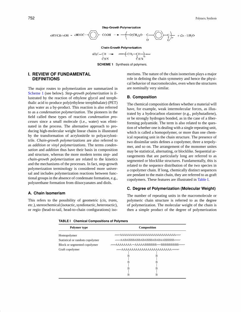
P1: GNH/GRI P2: GTV Final pages
Encyclopedia of Physical Science and Technology EN012B-596 July 27, 2001 18:18
752 Polymers, Synthesis
SCHEME 1 Synthesis of polymers.
I. REVIEW OF FUNDAMENTALDEFINITIONS
The major routes to polymerization are summarized inScheme 1 (see below). Step-growth polymerization is il-lustrated by the reaction of ethylene glycol and tereph-thalic acid to produce poly(ethylene terephthalate) (PET)plus water as a by-product. This reaction is also referredto as a condensation polymerization. The pioneers in thefield called these types of reaction condensation pro-cesses since a small molecule (i.e., water) was elimi-nated in the process. The alternative approach to pro-ducing high-molecular weight linear chains is illustratedby the transformation of acrylonitrile to polyacryloni-trile. Chain-growth polymerizations are also referred toas addition or vinyl polymerizations. The terms conden-sation and addition thus have their basis in compositionand structure, whereas the more modern terms step- andchain-growth polymerization are related to the kineticsand the mechanisms of the processes. In fact, step-growthpolymerization terminology is considered more univer-sal and includes polymerization reactions between func-tional groups in the absence of condensate formation, e.g.,polyurethane formation from diisocyanates and diols.
A. Chain Isomerism
This refers to the possibility of geometric (cis, trans,etc.), stereochemical (isotactic, syndiotactic, heterotactic),or regio (head-to-tail, head-to-chain configurations) iso-
TABLE I Chemical Compositions of Polymers
Polymer type Composition
Homopolymer AAAAAAAAAAAAAAAAAAAAAAAAAAAA
Statistical or random copolymer AABABBBABBABABBBABABAABBBBB
Block or segmented copolymer AAAAAAAA AAAAABBBBBB BBBBBBBBB
Graft copolymer AAAAAAAAAAAAAAAAAAAAAAAAA
B
B
B
B
B
B
B
B
merisms. The nature of the chain isomerism plays a majorrole in defining the chain symmetry and hence the physi-cal behavior of macromolecules, even when the structuresare nominally very similar.
B. Composition
The chemical composition defines whether a material willhave, for example, weak intermolecular forces, as illus-trated by a hydrocarbon elastomer (e.g., polybutadiene),or be strongly hydrogen bonded, as in the case of a fiber-forming polyamide. The term is also related to the ques-tion of whether one is dealing with a single repeating unit,which is called a homopolymer, or more than one chem-ical repeating unit in the chain structure. The presence oftwo dissimilar units defines a copolymer, three a terpoly-mer, and so on. The arrangement of the monomer unitesmay be statistical, alternating, or blocklike. Sequential ar-rangements that are particularly long are referred to assegmented or blocklike structures. Fundamentally, this isrelated to the sequence distribution of the two species ina copolymer chain. If long, chemically distinct sequencesare pendant to the main chain, they are referred to as graftcopolymers. These features are illustrated in Table I.
C. Degree of Polymerization (Molecular Weight)
The number of repeating units in the macromolecule orpolymeric chain structure is referred to as the degreeof polymerization. The molecular weight of the chain isthen a simple product of the degree of polymerization
P1: GNH/GRI P2: GTV Final pages
Encyclopedia of Physical Science and Technology EN012B-596 July 27, 2001 18:18
Polymers, Synthesis 753
multiplied by the molecular weight of the structure withinthe repeating unit. The molecular weights of syntheticmacromolecules usually exhibit a distribution in size. Thedistributions are often Gaussian, but may also approach thePoisson distributions in living and more controlled poly-merization processes. An example is provided below forpolystyrene. Thus, Mn is the number-average molecularweight, which is a product of N , the degree of polymer-ization, times 104 g/mole. The end groups R and R′ arenegligible at high Mn:
R (CH2 CH)n R�
D. Living and Controlled Polymerization
Polymerization reactions wherein the terminal unit of thegrowing chain species has an indefinitely long lifetimeand will essentially react only with the monomer arecalled living or controlled polymerizations. Such behav-ior permits molecular weight to increase linearly withconversion and provides terminally active species, whichmay initiate distinctly different monomer structures, thusproducing blocklike copolymers. This is particularlyimportant for carbanion polymerizations, as illustratedby the organolithium polymerizations of hydrocarbonmonomers. Research has shown that other types of reactiveintermediates, including coordination species with par-ticular attention to metallocene and single-site catalysts,appropriate cationic or oxonium ion species and reversiblystabilize free radical processes. Recent efforts in con-trolled radical polymerization processes have focused onstable free radical polymerization (SFRP) using nitroxidemediation, atom transfer radical polymerization (ATRP),and radical addition fragmentation transfer (RAFT). Theuse of “living” or “controlled” terminology depends onthe mechanism of polymerization, and the “living” clas-sification is often reserved for processes where the ratesof transfer or termination equal zero during propagation.
E. Step-Growth (Polycondensation)Polymerization
In these processes a macromolecule is built up via a seriesof reactions between functional groups, for example, thehydroxyl–carboxyl reaction, to produce a macromoleculeat very high conversions (>99.9%).
F. Chain-Grown (Addition) Polymerization
In this process a reactive small molecule (often contain-ing an alkene group) is transformed via radical or ionicintermediates into a macromolecule by a series of addi-
tion reactions. The latter may involve several distinct ki-netic chain-growth steps such as initiation, propagation,and possibly termination. The reaction is most importantfor the preparation of poly(ethylenes), poly(acrylates),poly(styrenes), poly(dienes), and related mono- or disub-stituted analogs.
II. BASIC CONSIDERATIONS
A number of important requirements must be met if smallmolecules (on the left side of the arrows in Scheme 1) are tobe efficiently transformed into macromolecular structures.One critical concept is the idea of functionality. In a step-growth polymerization, in order to achieve high molec-ular weight, it is essential that the reactions be perfectlydifunctional. For example, if we reacted only one of the hy-droxyl or carboxyl groups, we would make simply a smallmolecule. Indeed, the idea of a step-growth reaction is thatthe reaction can proceed from both ends of the molecule. Itmust proceed until high values of n, the degree of polymer-ization, are achieved. Typical number-average molecularweights for step-growth polymers, such as poly(ethyleneterephthalate), are 20,000–30,000 g/mole (Da).
By contrast, typical chain-growth reactions are requiredto proceed to significantly higher molecular weights, per-haps 100,000–200,000 g/mole or higher in the case ofpolyacrylonitrile and related so-called vinyl polymers.The term vinyl polymer refers to the fact that the chainmolecule is derived from a “vinyl-containing” starting ma-terial, even though the addition produces a saturated chain.The chain-growth reaction occurs in several distinct steps.Initiation, propagation, and terminated processes are in-volved as the kinetic chain begins to react, propagates, andfinally terminates. Thus, there are a number of differencesbetween these two fundamental routes of polymerization.In the step-growth case, only one reaction is responsiblefor polymer formation. In the example, this is esterifi-cation. By contrast, in the chain-growth case, initiation,propagation, and termination reactions proceed at differ-ent rates and possibly different mechanisms. During thepolymer-growth step, any two molecular species presentcan react during a step process, and one typically observesa slow, random growth taking place. Again, by contrast,the growth step in the chain reaction usually occurs bythe rapid addition of one unit at a time to the active endof the polymer chain. As we shall demonstrate later, theactive ends will be the typical intermediates of organicchemistry, such as radicals, anions, cations, and coordi-nation complexes. The point of the discussion here is thatthe molecular weights vary quite differently as a functionof conversion for the two systems. This is illustrated inFig. 1. In the case of the step-growth reactions, molecularweight increases only slowly until one reaches very highconversions. In fact, the overall process is governed by

P1: GNH/GRI P2: GTV Final pages
Encyclopedia of Physical Science and Technology EN012B-596 July 27, 2001 18:18
754 Polymers, Synthesis
FIGURE 1 Molecular weight versus percent conversion for(a) step-growth polymerization and (b) chain growth polymeriza-tion and living polymerization processes.
the fractional extent of conversion, usually designated P .For example, if one started a reaction with 1 mole of car-boxylic acid, it would be necessary to consume ∼99% ofthat mole; in other words, reduce the concentration to 0.01mole, before one could anticipate reaching high molecu-lar weight. The degree of polymerization is proportionalto 1/(1 − P), where P is the fractional extent of reaction.
This means that there are a number of requirementsfor obtaining high molecular weight. First, one must workwith very pure monomers. Typical purities of commercial-grade monomers are 99.99%. If they were less than 99%pure, it would be impossible to make more than 100 unitsin a chain, which would generally be insufficient to obtainadequate mechanical properties. Second, if coreactants areutilized, a perfect stoichiometric balance of the two difunc-tional monomers must be introduced. Third, there must beno side reactions. Finally, conditions must exist that willallow the reaction to be pushed to very high conversions.This implies the absence of any side reactions. In essence,step-growth polymerization can be viewed as a form ofquantitative organic chemistry. Most organic reactionsare not suitable for obtaining such high yields. Surpris-ingly, however, a large number of systems have been pro-duced in the laboratory, not only from simple polyestersand polyamides, but also from high-temperature materi-als, such as polyimides and liquid crystalline polymers.The only necessity is that the four requirements discussedabove be met for any of the step-growth polymerizationsystems.
Chain-growth reactions, by contrast, often show molec-ular weight versus conversion curves, as illustrated in thelower portion of Fig. 1. Free-radical reactions that in-volve initiation, propagation, and termination often yieldhigh-molecular weight chains at very low conversions.
Thus, one can imagine only a small percentage of themonomer being activated per unit time, and perhaps onlyabout 10−8 mole/liter of growing chains may be activeat any one time. In this case, the monomer concentra-tion will decrease steadily throughout the reaction. Livingpolymerizations continue to receive intense academic andindustrial attention. In a living polymerization, in whichthe chain-end activity is maintained throughout the over-all polymerization (the rate of any transfer or termina-tion steps is essentially zero), one may observe molecularweight increasing linearly with conversion. Such polymer-izations are of great interest since they allow predictablemolecular weights and narrow molecular weight distribu-tions to be obtained, as well as the possible generation ofblock copolymers by the use of the active chain end of onespecies to initiate a new monomer.
III. LINEAR STEP-GROWTHPOLYMERIZATIONS
In Scheme 2, a direct esterification process illustrates lin-ear step-growth polymerization. The implication is thatall of the oligomeric species are capable of reacting withsuitably terminated species. Therefore, as the molecularweight slowly builds through the early portion of the reac-tion, a variety of oligomeric sizes exist that must react withone another to ultimately generate high molecular weight.These reactions are often protic or Lewis acid-catalyzed,as illustrated, to allow the protonated species to be morereadily attacked by the nucleophile. This is consistent withthe usual mechanics in small-molecule esterification.
Since the esterification is an equilibrium process, watertypically has to be removed in order to drive the reactionto the right, that is, toward higher molecular weight. Thepolymerization rate in such a case is proportional to thegroup collision frequency and not dependent on the dif-fusion rate of the entire chain. The statistical segment ismore mobile than the whole molecule. Many workers havedemonstrated that the second functional group on a grow-ing chain is not influenced by the first if several carbonatoms separate it. Essentially, this leads to the principleof equal reactivity. This implies essentially that the reac-tivity of the growing molecules will not change signifi-cantly during most of the polymerization process. Thereare some exceptions to this, based on highly sterically re-stricted groups, and, of course, heterogeneous processeswould also not fall into this category. Nevertheless, theprinciple of equal reactivity has made it possible to treatthese reactions statistically. The fact that the molecularweights and molecular distributions can be predicted thisway is an indication that the principle is typically correct.Another way of looking at this process is summarized inScheme 3. Any two species in the reaction mixture must

P1: GNH/GRI P2: GTV Final pages
Encyclopedia of Physical Science and Technology EN012B-596 July 27, 2001 18:18
Polymers, Synthesis 755
SCHEME 2 Linear step-growth processes: polyesterifications.
react with one another, whether they are dimers reactingwith monomers, trimers, or higher species. In the gen-eral case, one considers an n-mer reacting with an m-merto produce the next higher oligomer. This whole processmust continue until P begins to approach 0.99 or higher.
A second illustration of a linear step-growth polymer-ization is the synthesis of polyesters via ester interchangeprocesses (Scheme 4). Here, one utilizes the dimethylester of terephthalic acid with, initially, an excess of ethy-lene glycol. Historically, the choice of the dimethylester was based on considerations of monomer purity.Thus, in early industrial practice, it was not feasibleto produce nearly 100% pure terephthalic acid. Sinceterephthalic acid cannot be distilled, early investigatorstook recourse to producing the dimethyl ester, whichcould be vacuum-distilled and also crystallized, thusallowing one to meet the criterion of extremely highmonomer purity. The dimethyl ester then will react witha diol, such as ethylene glycol, in the manner indicated.
SCHEME 3 Examples of step-growth polymerization. Any twospecies in the reaction mixture can react with one another.
Ester interchange processes will proceed and producemethanol, which is removed. Ideally, the structure isbis(hydroxyethyl) terephthalate. Actually, some higheroligomers may also be formed at this stage, but the pointis that the new structure has both hydroxyl and esterfunctionality in the same molecule.
Sometimes it is common to term such a new monomeran AB system. This is contrasted with a so-called AA +
SCHEME 4 Synthesis of polyesters via ester interchange.
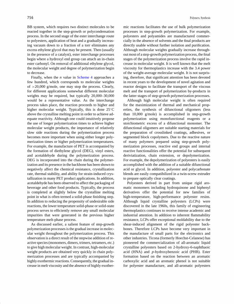
P1: GNH/GRI P2: GTV Final pages
Encyclopedia of Physical Science and Technology EN012B-596 July 27, 2001 18:18
756 Polymers, Synthesis
BB system, which requires two distinct molecules to bereacted together in the step-growth or polycondensationprocess. In the second stage of the ester interchange routeto polyesters, application of heat and a gradually increas-ing vacuum down to a fraction of a torr eliminates anyexcess ethylene glycol that may be present. Then (usuallyin the presence of a catalyst), ester interchange processesbegin where a hydroxyl end group can attach an in-chainester carbonyl. On removal of additional ethylene glycol,the molecular weight and degree of polymerization beginto decrease.
Finally, when the n value in Scheme 4 approaches afew hundred, which corresponds to molecular weightsof >20,000 g/mole, one may stop the process. Clearly,for different applications somewhat different molecularweights may be required, but typically 20,000–30,000would be a representative value. As the interchangeprocess takes place, the reaction proceeds to higher andhigher molecular weight. Typically, this is done 25◦Cabove the crystalline melting point in order to achieve ad-equate reactivity. Although one could intuitively proposethe use of longer polymerization times to achieve highermolecular weight products, the importance of relativelyslow side reactions during the polymerization processbecomes more important when using either longer poly-merization times or higher polymerization temperatures.For example, the manufacture of PET is accompanied bythe formation of diethylene glycol (DEG), vinyl esters,and acetaldehyde during the polymerization process.DEG is incorporated into the chain during the polymer-ization and its presence in the backbone has been shown tonegatively affect the chemical resistance, crystallizationrate, thermal stability, and ability for strain-induced crys-tallization in many PET product applications. In addition,acetaldehyde has been observed to affect the packaging ofbeverage and other food products. Typically, the processis completed at slightly below the crystalline meltingpoint in what is often termed a solid-phase finishing step.In addition to reducing the propensity of undesirable sidereactions, the lower temperature solid-phase or solid-stateprocess serves to efficiently remove any small molecularimpurities that were generated in the previous highertemperature melt-phase process.
As discussed earlier, a salient feature of step-growthpolymerization processes is the gradual increase in molec-ular weight throughout the polymerization process. Thisobservation is a direct result of the stepwise addition of re-active species (monomers, dimers, trimers, tetramers, etc.)to give high molecular weight. In contrast, high-molecularweight products are obtained very quickly in chain poly-merization processes and are typically accompanied byhighly exothermic reactions. Consequently, the gradual in-crease in melt viscosity and the absence of highly exother-
mic reactions facilitates the use of bulk polymerizationprocesses in step-growth polymerization. For example,polyesters and polyamides are manufactured commer-cially in the absence of solvents and the final products aredirectly usable without further isolation and purification.Although molecular weights gradually increase through-out most of a step-growth polymerization process, the finalstages of the polymerization process involve the rapid in-crease in molecular weight. It is well known that the meltviscosity for thermoplastics increase with the 3.4 powerof the weight-average molecular weight. It is not surpris-ing, therefore, that significant attention has been devotedin recent years to the development of novel agitation andreactor designs to facilitate the transport of the viscousmelt and the transport of polymerization by-products inthe latter stages of step-growth polymerization processes.
Although high molecular weight is often requiredfor the maximization of thermal and mechanical prop-erties, the synthesis of difunctional oligomers (lessthan 10,000 g/mole) is accomplished in step-growthpolymerization using monofunctional reagents or astoichiometric excess of a difunctional monomer. Thedifunctional oligomers are suitable starting materials forthe preparation of crosslinked coatings, adhesives, orsegmented block copolymers. Due to the reactive natureof many polymers prepared using step-growth poly-merization processes, reactive end groups and internalreactive functionalities offer the potential for subsequentderiviatization, chain extension, or depolymerization.For example, the depolymerization of polyesters is easilyaccomplished with the addition of a suitable difunctionalacid or glycol. In addition, polyester and polycarbonateblends are easily compatibilized in a twin-screw extruderto prepare optically clear coatings.
Polyesters derived in part from unique rigid aro-matic monomers including hydroquinone and biphenylderivatives offer the potential for new families ofhigh-temperature, high-performance polyester resins.Although liquid crystalline polyesters (LCPs) werediscovered in the late 1960s, this family of engineeringthermoplastics continues to receive intense academic andindustrial attention. In addition to inherent flammabilityresistance, LCPs offer exceptional moldability due to theshear-induced alignment of the rigid polyester back-bones. Therefore LCPs have become very important inthe manufacture of small parts for the electronics andother industries. Ticona (formerly Hoechst-Celanese) haspioneered the commercialization of all-aromatic liquidcrystalline polyesters based on 2-hydroxy-6-naphthaoicacid (HNA) and p-hydroxybenzoic acid (PHB). Esterformation based on the reaction between an aromaticcarboxylic acid and an aromatic phenol is not suitablefor polyester manufacture, and all-aromatic polyesters

P1: GNH/GRI P2: GTV Final pages
Encyclopedia of Physical Science and Technology EN012B-596 July 27, 2001 18:18
Polymers, Synthesis 757
require the in situ acetylation of the aromatic phenols.Condensation of the acetate and aromatic carboxylicacid readily occurs at 250◦C with the liberation ofacetic acid, and the polymerization mechanism is oftenreferred to as acidolysis. Although the polymerizationmechanism appears straightforward, Hall and coworkershave recently elucidated the very complex nature of thispolymerization process. Industrial attention has focusedon the development of suitable manufacturing processesthat can handle the corrosive reaction environment and thehigh polymerization temperatures required in the viscousmelt phase. Significant attention has also been devotedto the preparation of liquid crystalline polyesters derivedfrom aliphatic glycols and biphenyl dicarboxylic acids.
Many excellent reviews are available on the synthesisof nylons. Melt-phase polycondensation processes synthe-size most aliphatic and partially aromatic nylons commer-cially. In cases where crystalline polyamides are preparedand melt-phase viscosities limit desired molecular weightformation, sold-state polymerization processes have beenemployed. For nylons, the formation of the “nylon salt”is very useful in purifying the monomers and obtainingthe exact stoichiometry to be able to get a high degreeof polymerization. Unlike polyesters, the equilibrium ina polyamide condensation lies for to the right and thusthe polymerizations can be charged stoichiometrically andinitially run under pressure to react all the diamine andmaintain the stoichiometry. The step-growth process forpolyamides is illustrated in Scheme 5. The reaction prod-uct of hexamethylenediamine and adipic acid produces
SCHEME 5 Synthesis of polyamides.
the largest volume polyamide, or nylon, in the world. Thisis called poly(hexamethylene adipamide), but in addition,the common nylon terminology is frequently used. Nylonnomenclature is based simply on the number of carbonsin the reactants. Thus, there are six methylenes in hexam-ethylenediamine and six carbons in adipic acid, hence, theterm Nylon 6,6.
In order to achieve perfect stoichiometry in the AABBsystem, one relies on the capacity of these species to forma one-to-one “nylon salt,” which essentially is an ammo-nium carboxylate, as indicated. On carefully heating theammonium carboxylate to ∼200◦C initially, then as highas 280◦C in order to exceed the crystalline melting pointof the polymer, one can transform the ionic carboxylateinto amide bonds with the release of water. The termi-nal amine groups of the oligomeric polyamides react withterminal carboxylic acid groups until appropriate high-molecular weight materials are obtained. The molecularweight is typically 20,000–30,000 for many fiber-formingpolymers.
Many variations on polyesters and polyamides arepossible, and in the case of wholy aromatic systems it iscommon to use either solution or interfacial processes,as depicted in Scheme 6. Due to the lower reactivityof aromatic amines and aromatic bisphenols, it is oftennecessary in these cases to utilize the more reactiveacid chloride derivative of carboxylic acids. Thus, manyaromatic polyamides and polyesters are known and areimportant in both fiber and thermoplastic materialstechnology. In these systems, either terephthaloyl orisophthaloyl chlorides or mixtures of the two are usedfrequently to disrupt the chain symmetry and produceamorphous materials. Utilization of a single componentmay allow crystalline textures to be produced that areimportant, for example, in fiber technology.
A much different solution process involves the use of di-aryl halides and diamines to prepare aramids via the Heckcarbonylation reaction. This route to aramids was first dis-closed using dibromo aromatics. Relatively low molecu-lar weight polymers were formed. Diiodo aromatics werefound to react at a much higher rate and to give polymersof much higher ultimate molecular weight, presumablydue to fewer side reactions. This process eliminates theuse of corrosive and moisture-sensitive acid chlorides, butrequires the use of expensive palladium catalysts.
Other important polymers are synthesized via step-growth polymerization, although we shall provide onlyfour additional examples that have received significant at-tention. Since the early 1960s polycarbonates have be-come an extremely important and fast-growing, clear,amorphous thermoplastic for injection molding and ex-truded sheet products. The workhorse polycarbonate resinis based on bisphenol A (BPA PC) and has a unique
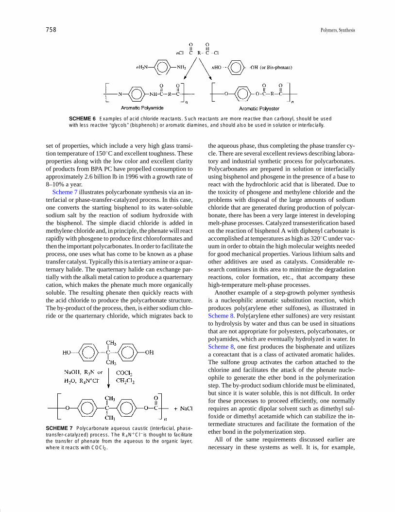
P1: GNH/GRI P2: GTV Final pages
Encyclopedia of Physical Science and Technology EN012B-596 July 27, 2001 18:18
758 Polymers, Synthesis
SCHEME 6 Examples of acid chloride reactants. Such reactants are more reactive than carboxyl, should be usedwith less reactive “glycols” (bisphenols) or aromatic diamines, and should also be used in solution or interfacially.
set of properties, which include a very high glass transi-tion temperature of 150◦C and excellent toughness. Theseproperties along with the low color and excellent clarityof products from BPA PC have propelled consumption toapproximately 2.6 billion lb in 1996 with a growth rate of8–10% a year.
Scheme 7 illustrates polycarbonate synthesis via an in-terfacial or phase-transfer-catalyzed process. In this case,one converts the starting bisphenol to its water-solublesodium salt by the reaction of sodium hydroxide withthe bisphenol. The simple diacid chloride is added inmethylene chloride and, in principle, the phenate will reactrapidly with phosgene to produce first chloroformates andthen the important polycarbonates. In order to facilitate theprocess, one uses what has come to be known as a phasetransfer catalyst. Typically this is a tertiary amine or a quar-ternary halide. The quarternary halide can exchange par-tially with the alkali metal cation to produce a quarternarycation, which makes the phenate much more organicallysoluble. The resulting phenate then quickly reacts withthe acid chloride to produce the polycarbonate structure.The by-product of the process, then, is either sodium chlo-ride or the quarternary chloride, which migrates back to
SCHEME 7 Polycarbonate aqueous caustic (interfacial, phase-transfer-catalyzed) process. The R4N+Cl−is thought to facilitatethe transfer of phenate from the aqueous to the organic layer,where it reacts with COCl2.
the aqueous phase, thus completing the phase transfer cy-cle. There are several excellent reviews describing labora-tory and industrial synthetic process for polycarbonates.Polycarbonates are prepared in solution or interfaciallyusing bisphenol and phosgene in the presence of a base toreact with the hydrochloric acid that is liberated. Due tothe toxicity of phosgene and methylene chloride and theproblems with disposal of the large amounts of sodiumchloride that are generated during production of polycar-bonate, there has been a very large interest in developingmelt-phase processes. Catalyzed transesterification basedon the reaction of bisphenol A with diphenyl carbonate isaccomplished at temperatures as high as 320◦C under vac-uum in order to obtain the high molecular weights neededfor good mechanical properties. Various lithium salts andother additives are used as catalysts. Considerable re-search continues in this area to minimize the degradationreactions, color formation, etc., that accompany thesehigh-temperature melt-phase processes.
Another example of a step-growth polymer synthesisis a nucleophilic aromatic substitution reaction, whichproduces poly(arylene ether sulfones), as illustrated inScheme 8. Poly(arylene ether sulfones) are very resistantto hydrolysis by water and thus can be used in situationsthat are not appropriate for polyesters, polycarbonates, orpolyamides, which are eventually hydrolyzed in water. InScheme 8, one first produces the bisphenate and utilizesa coreactant that is a class of activated aromatic halides.The sulfone group activates the carbon attached to thechlorine and facilitates the attack of the phenate nucle-ophile to generate the ether bond in the polymerizationstep. The by-product sodium chloride must be eliminated,but since it is water soluble, this is not difficult. In orderfor these processes to proceed efficiently, one normallyrequires an aprotic dipolar solvent such as dimethyl sul-foxide or dimethyl acetamide which can stabilize the in-termediate structures and facilitate the formation of theether bond in the polymerization step.
All of the same requirements discussed earlier arenecessary in these systems as well. It is, for example,
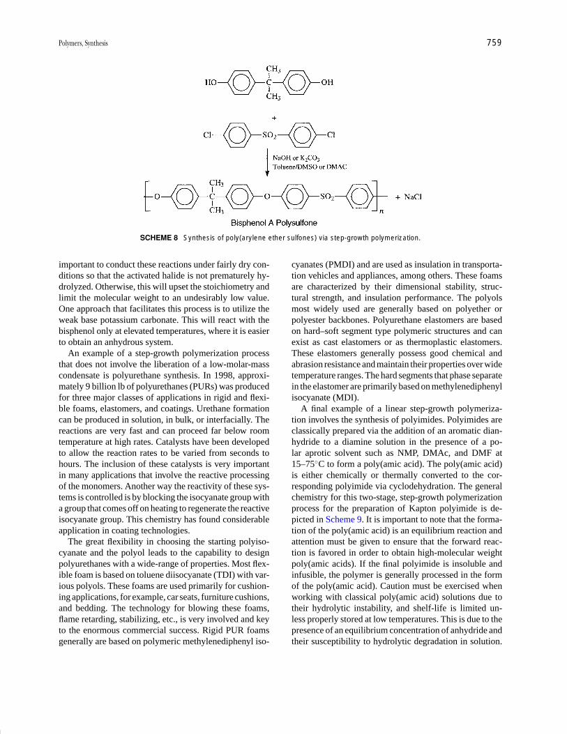
P1: GNH/GRI P2: GTV Final pages
Encyclopedia of Physical Science and Technology EN012B-596 July 27, 2001 18:18
Polymers, Synthesis 759
SCHEME 8 Synthesis of poly(arylene ether sulfones) via step-growth polymerization.
important to conduct these reactions under fairly dry con-ditions so that the activated halide is not prematurely hy-drolyzed. Otherwise, this will upset the stoichiometry andlimit the molecular weight to an undesirably low value.One approach that facilitates this process is to utilize theweak base potassium carbonate. This will react with thebisphenol only at elevated temperatures, where it is easierto obtain an anhydrous system.
An example of a step-growth polymerization processthat does not involve the liberation of a low-molar-masscondensate is polyurethane synthesis. In 1998, approxi-mately 9 billion lb of polyurethanes (PURs) was producedfor three major classes of applications in rigid and flexi-ble foams, elastomers, and coatings. Urethane formationcan be produced in solution, in bulk, or interfacially. Thereactions are very fast and can proceed far below roomtemperature at high rates. Catalysts have been developedto allow the reaction rates to be varied from seconds tohours. The inclusion of these catalysts is very importantin many applications that involve the reactive processingof the monomers. Another way the reactivity of these sys-tems is controlled is by blocking the isocyanate group witha group that comes off on heating to regenerate the reactiveisocyanate group. This chemistry has found considerableapplication in coating technologies.
The great flexibility in choosing the starting polyiso-cyanate and the polyol leads to the capability to designpolyurethanes with a wide-range of properties. Most flex-ible foam is based on toluene diisocyanate (TDI) with var-ious polyols. These foams are used primarily for cushion-ing applications, for example, car seats, furniture cushions,and bedding. The technology for blowing these foams,flame retarding, stabilizing, etc., is very involved and keyto the enormous commercial success. Rigid PUR foamsgenerally are based on polymeric methylenediphenyl iso-
cyanates (PMDI) and are used as insulation in transporta-tion vehicles and appliances, among others. These foamsare characterized by their dimensional stability, struc-tural strength, and insulation performance. The polyolsmost widely used are generally based on polyether orpolyester backbones. Polyurethane elastomers are basedon hard–soft segment type polymeric structures and canexist as cast elastomers or as thermoplastic elastomers.These elastomers generally possess good chemical andabrasion resistance and maintain their properties over widetemperature ranges. The hard segments that phase separatein the elastomer are primarily based on methylenediphenylisocyanate (MDI).
A final example of a linear step-growth polymeriza-tion involves the synthesis of polyimides. Polyimides areclassically prepared via the addition of an aromatic dian-hydride to a diamine solution in the presence of a po-lar aprotic solvent such as NMP, DMAc, and DMF at15–75◦C to form a poly(amic acid). The poly(amic acid)is either chemically or thermally converted to the cor-responding polyimide via cyclodehydration. The generalchemistry for this two-stage, step-growth polymerizationprocess for the preparation of Kapton polyimide is de-picted in Scheme 9. It is important to note that the forma-tion of the poly(amic acid) is an equilibrium reaction andattention must be given to ensure that the forward reac-tion is favored in order to obtain high-molecular weightpoly(amic acids). If the final polyimide is insoluble andinfusible, the polymer is generally processed in the formof the poly(amic acid). Caution must be exercised whenworking with classical poly(amic acid) solutions due totheir hydrolytic instability, and shelf-life is limited un-less properly stored at low temperatures. This is due to thepresence of an equilibrium concentration of anhydride andtheir susceptibility to hydrolytic degradation in solution.
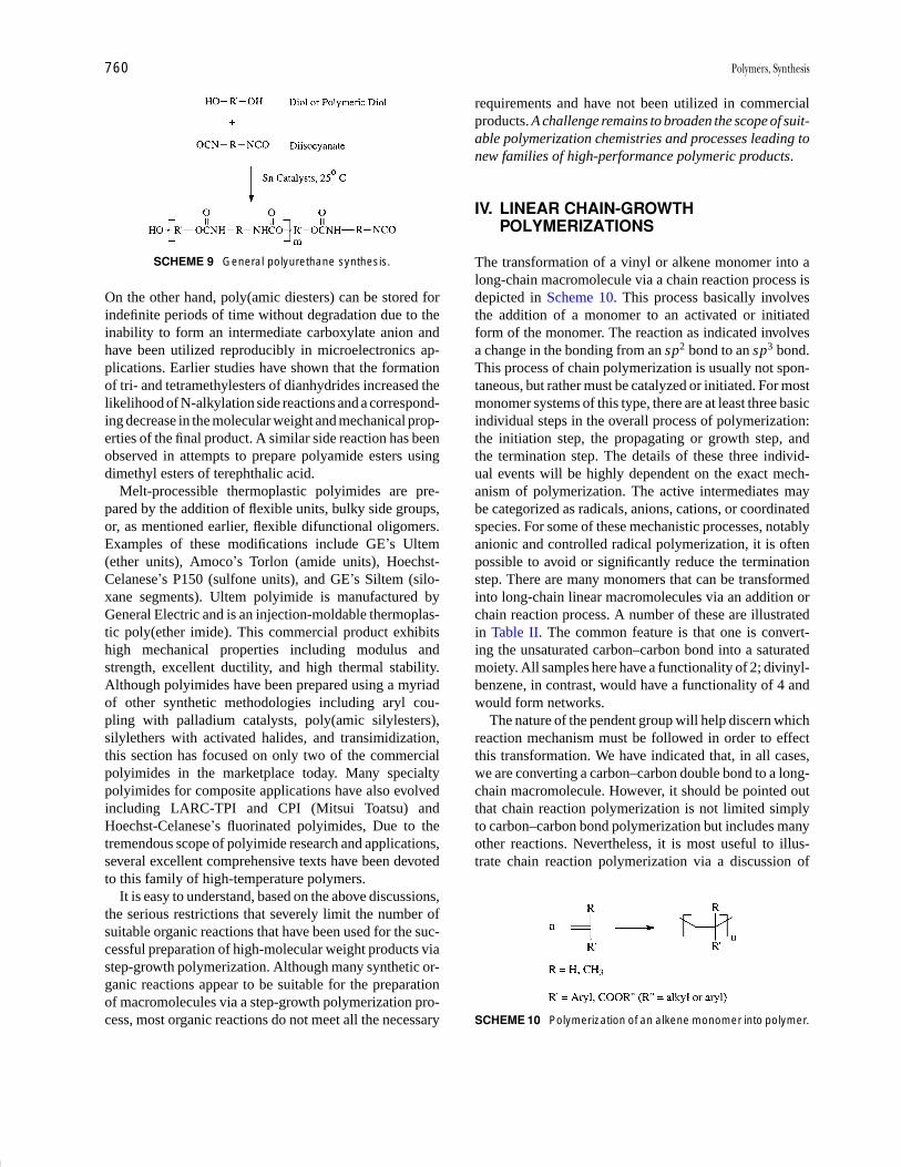
P1: GNH/GRI P2: GTV Final pages
Encyclopedia of Physical Science and Technology EN012B-596 July 27, 2001 18:18
760 Polymers, Synthesis
SCHEME 9 General polyurethane synthesis.
On the other hand, poly(amic diesters) can be stored forindefinite periods of time without degradation due to theinability to form an intermediate carboxylate anion andhave been utilized reproducibly in microelectronics ap-plications. Earlier studies have shown that the formationof tri- and tetramethylesters of dianhydrides increased thelikelihood of N-alkylation side reactions and a correspond-ing decrease in the molecular weight and mechanical prop-erties of the final product. A similar side reaction has beenobserved in attempts to prepare polyamide esters usingdimethyl esters of terephthalic acid.
Melt-processible thermoplastic polyimides are pre-pared by the addition of flexible units, bulky side groups,or, as mentioned earlier, flexible difunctional oligomers.Examples of these modifications include GE’s Ultem(ether units), Amoco’s Torlon (amide units), Hoechst-Celanese’s P150 (sulfone units), and GE’s Siltem (silo-xane segments). Ultem polyimide is manufactured byGeneral Electric and is an injection-moldable thermoplas-tic poly(ether imide). This commercial product exhibitshigh mechanical properties including modulus andstrength, excellent ductility, and high thermal stability.Although polyimides have been prepared using a myriadof other synthetic methodologies including aryl cou-pling with palladium catalysts, poly(amic silylesters),silylethers with activated halides, and transimidization,this section has focused on only two of the commercialpolyimides in the marketplace today. Many specialtypolyimides for composite applications have also evolvedincluding LARC-TPI and CPI (Mitsui Toatsu) andHoechst-Celanese’s fluorinated polyimides, Due to thetremendous scope of polyimide research and applications,several excellent comprehensive texts have been devotedto this family of high-temperature polymers.
It is easy to understand, based on the above discussions,the serious restrictions that severely limit the number ofsuitable organic reactions that have been used for the suc-cessful preparation of high-molecular weight products viastep-growth polymerization. Although many synthetic or-ganic reactions appear to be suitable for the preparationof macromolecules via a step-growth polymerization pro-cess, most organic reactions do not meet all the necessary
requirements and have not been utilized in commercialproducts. A challenge remains to broaden the scope of suit-able polymerization chemistries and processes leading tonew families of high-performance polymeric products.
IV. LINEAR CHAIN-GROWTHPOLYMERIZATIONS
The transformation of a vinyl or alkene monomer into along-chain macromolecule via a chain reaction process isdepicted in Scheme 10. This process basically involvesthe addition of a monomer to an activated or initiatedform of the monomer. The reaction as indicated involvesa change in the bonding from an sp2 bond to an sp3 bond.This process of chain polymerization is usually not spon-taneous, but rather must be catalyzed or initiated. For mostmonomer systems of this type, there are at least three basicindividual steps in the overall process of polymerization:the initiation step, the propagating or growth step, andthe termination step. The details of these three individ-ual events will be highly dependent on the exact mech-anism of polymerization. The active intermediates maybe categorized as radicals, anions, cations, or coordinatedspecies. For some of these mechanistic processes, notablyanionic and controlled radical polymerization, it is oftenpossible to avoid or significantly reduce the terminationstep. There are many monomers that can be transformedinto long-chain linear macromolecules via an addition orchain reaction process. A number of these are illustratedin Table II. The common feature is that one is convert-ing the unsaturated carbon–carbon bond into a saturatedmoiety. All samples here have a functionality of 2; divinyl-benzene, in contrast, would have a functionality of 4 andwould form networks.
The nature of the pendent group will help discern whichreaction mechanism must be followed in order to effectthis transformation. We have indicated that, in all cases,we are converting a carbon–carbon double bond to a long-chain macromolecule. However, it should be pointed outthat chain reaction polymerization is not limited simplyto carbon–carbon bond polymerization but includes manyother reactions. Nevertheless, it is most useful to illus-trate chain reaction polymerization via a discussion of
SCHEME 10 Polymerization of an alkene monomer into polymer.
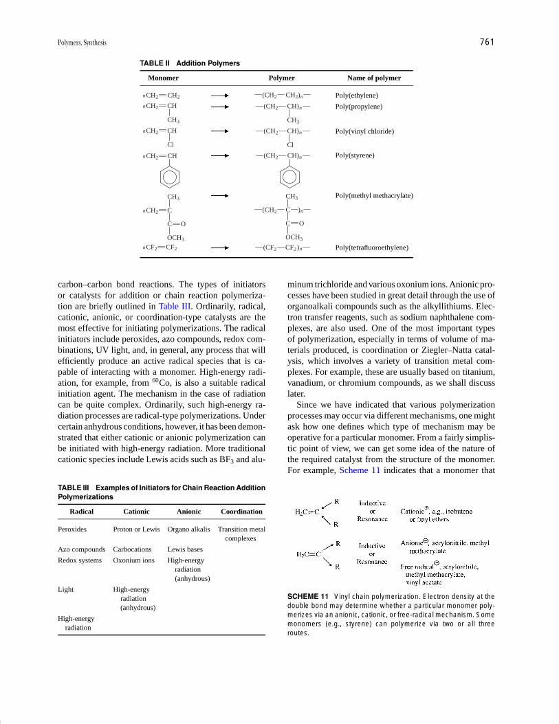
P1: GNH/GRI P2: GTV Final pages
Encyclopedia of Physical Science and Technology EN012B-596 July 27, 2001 18:18
Polymers, Synthesis 761
TABLE II Addition Polymers
Monomer Polymer Name of polymer
nCH2 CH2 n(CH2 CH2) Poly(ethylene)nCH2 CH
CH3
n(CH2 CH)
CH3
Poly(propylene)
nCH2 CH
Cl
n(CH2 CH)
Cl
Poly(vinyl chloride)
nCH2 CH n(CH2 CH) Poly(styrene)
nCH2 C
CH3
C O
OCH3
n(CH2 C
CH3
C O
OCH3
)
Poly(methyl methacrylate)
nCF2 CF2 n(CF2 CF2) Poly(tetrafluoroethylene)
carbon–carbon bond reactions. The types of initiatorsor catalysts for addition or chain reaction polymeriza-tion are briefly outlined in Table III. Ordinarily, radical,cationic, anionic, or coordination-type catalysts are themost effective for initiating polymerizations. The radicalinitiators include peroxides, azo compounds, redox com-binations, UV light, and, in general, any process that willefficiently produce an active radical species that is ca-pable of interacting with a monomer. High-energy radi-ation, for example, from 60Co, is also a suitable radicalinitiation agent. The mechanism in the case of radiationcan be quite complex. Ordinarily, such high-energy ra-diation processes are radical-type polymerizations. Undercertain anhydrous conditions, however, it has been demon-strated that either cationic or anionic polymerization canbe initiated with high-energy radiation. More traditionalcationic species include Lewis acids such as BF3 and alu-
TABLE III Examples of Initiators for Chain Reaction AdditionPolymerizations
Radical Cationic Anionic Coordination
Peroxides Proton or Lewis Organo alkalis Transition metalcomplexes
Azo compounds Carbocations Lewis bases
Redox systems Oxonium ions High-energyradiation(anhydrous)
Light High-energyradiation(anhydrous)
High-energyradiation
minum trichloride and various oxonium ions. Anionic pro-cesses have been studied in great detail through the use oforganoalkali compounds such as the alkyllithiums. Elec-tron transfer reagents, such as sodium naphthalene com-plexes, are also used. One of the most important typesof polymerization, especially in terms of volume of ma-terials produced, is coordination or Ziegler–Natta catal-ysis, which involves a variety of transition metal com-plexes. For example, these are usually based on titanium,vanadium, or chromium compounds, as we shall discusslater.
Since we have indicated that various polymerizationprocesses may occur via different mechanisms, one mightask how one defines which type of mechanism may beoperative for a particular monomer. From a fairly simplis-tic point of view, we can get some idea of the nature ofthe required catalyst from the structure of the monomer.For example, Scheme 11 indicates that a monomer that
SCHEME 11 Vinyl chain polymerization. Electron density at thedouble bond may determine whether a particular monomer poly-merizes via an anionic, cationic, or free-radical mechanism. Somemonomers (e.g., styrene) can polymerize via two or all threeroutes.

P1: GNH/GRI P2: GTV Final pages
Encyclopedia of Physical Science and Technology EN012B-596 July 27, 2001 18:18
762 Polymers, Synthesis
contains electron-donating groups either via resonance orinductive interactions will polymerize via a carbocationmechanism. Examples are isobutene and the vinyl alkylether systems. Monomers of this type are very responsiveto cationic type of intiators, such as Lewis acids. Thus, theelectron density at the double bond can determine whethera monomer polymerizes via a cationic or an anionic pro-cess. A second example is a monomer in which electron-withdrawing groups such as ester groups or nitrile groupsare attached to the reactive site. Such a monomer is quitestable to cationic species but can very often be rapidlypolymerized by anionic initiators. On the other hand,there are a number of monomers of somewhat interme-diate electron densities, for example, vinyl acetate. Thesemonomers are primarily polymerized by only free-radicaltype of initiators. Such monomers may contain groups thatwould interfere with cations or anions (e.g., vinyl halides)and therefore must be polymerized only by free-radicalprocesses.
A. Free-Radical Chain Polymerizations
If one were to use a peroxide-type initiator, it would be ofgreat interest to understand how the groups attached to theoxygen bond influence the polymerization. Table IV listsseveral peroxide initiators and some suitable temperatureranges where they could be used. The common featurehere is the relatively weak oxygen–oxygen bond, whichis susceptible to homolytic cleavage. However, the groupsattached to the peroxy bond particularly influence the sta-bility of the radicals that are formed, and this in turn definesmore or less the temperature range within which a partic-
TABLE IV Peroxide Initiatorsa
PolymerizationStructure temperature range (◦C)
KO S O O S OK
O
O
O
O
30–80
H5C6 C O O C
O O
C6H5 40–100
H5C6 C O O H
CH3
CH3 50–120
H3C C O O
CH3
CH3
C CH3
CH3
CH3 80–150
a Groups bonded to the peroxide structure primarily affectthermal stability and/or solubility.
ular peroxide molecule could be used to effect polymer-ization. For example, a tertiary butyl group on a peroxidewill produce a tertiary butoxy radical, which is relativelystable. Therefore, initiators containing these groups areuseful at relatively high temperatures. The other principaleffect of structure is related to the solubility of a peroxideinitiator. A high percentage of organic groups will promoteorganic solubility, which is important in certain types ofpolymerizations, such as “suspension” reactions. On theother hand, if one wishes to have a water-soluble initia-tor, the initiator of choice may be potassium persulfatesince the potassium salt form is quite soluble in aque-ous media. A wide range of initiator structures has beenprepared, and many of these are commercially available.Nevertheless, there are some occasions when one wishesto generate a free-radical species at room temperature orslightly above.
Some additional free-radical decompositions are de-picted in Scheme 12. In particular, one should commenton the important class of azo initiators. The most im-portant of these is azobisisobutyronitrile (AIBN), whichdecomposes to generate a molecule of nitrogen plus anitrile-stabilized alkyl radical. The half-life of the poly-merization initiators can often be quite readily predicted,at least for model systems. The reaction rate follows first-order kinetics. There is a wide variety of vinyl monomersthat will undergo free-radical polymerizations. In gen-eral the pendant group is usually capable of producingresonance stabilization to the growing radical species.Scheme 13 shows several of the most important types ofmonomers that readily undergo free-radical polymeriza-tion; these include styrene, vinyl acetate, the acrylic andmethacrylate monomers, the vinyl halides, acrylonitrile,and the dienes. Various free-radical resonance forms canbe written in the case of styrene. The initiator moleculefirst decomposes into radical species, which add to thecarbon–carbon double bond. One should note that thereis a marked preference for so-called head-to-tail additionin most vinyl radical polymerizations. The head-to-tailaddition is favored both for the resonance reasons in-dicated and also because of steric effects. Head-to-headplacement in the case of styrene would produces twophenyl units adjacent to one another, which would be avery unlikely situation. For these reasons, head-to-tail ad-dition is the predominant mode of chain configurationfor vinyl polymerizations. The exceptions to this gen-erality usually involve monomers that have very smallpendant groups, which cannot contribute much resonancestabilization to the growing radical. The most importantclass of such monomers probably comprises the fluorine-containing monomers, since fluorine is small and doesnot have much tendency to resonance-stabilize a growingchain end. There are a number of systems of this type

P1: GNH/GRI P2: GTV Final pages
Encyclopedia of Physical Science and Technology EN012B-596 July 27, 2001 18:18
Polymers, Synthesis 763
SCHEME 12 Generation of some typical free radicals.
SCHEME 13 Free radical polymerization; X provides resonancestabilization to the growing radical.
that do have small but significant quantities of head-to-head and tail-to-tail addition steps. This has most oftenbeen demonstrated through the use of 19F NMR spec-troscopy. Even in this case, the abnormal addition is rela-tive minor and is of the order of ∼10% of the overall chainstructure.
The tacticity or stereochemistry of vinyl chains is a veryimportant parameter. Following the definitions of Natta(Scheme 14) it is common to depict chains as isotac-tic, syndiotactic, or atactic. The isotactic chains are ca-pable of undergoing crystallization and, indeed, isotac-tic polypropylene made via coordination polymerizationis a polymer of major commercial importance. Furthercomments on this process will be made later. Syndiotacticpolymers have placements of the R group on opposite sidesof an extended chain. It is also quite popular to characterizethe stereostructure by NMR in terms of meso or racemictypes of placements, diads, triads, pentads, and so on. Ingeneral, one should not that free-radical polymerizationtends to produce mostly atactic or heterotactic placements.There is some tendency to produce moderately high syn-diotactic structures in certain polar monomers, such asvinyl chloride or acrylonitrile. Moreover, the syndiotac-tic structure is favored as one reduces the polymerizationtemperature.
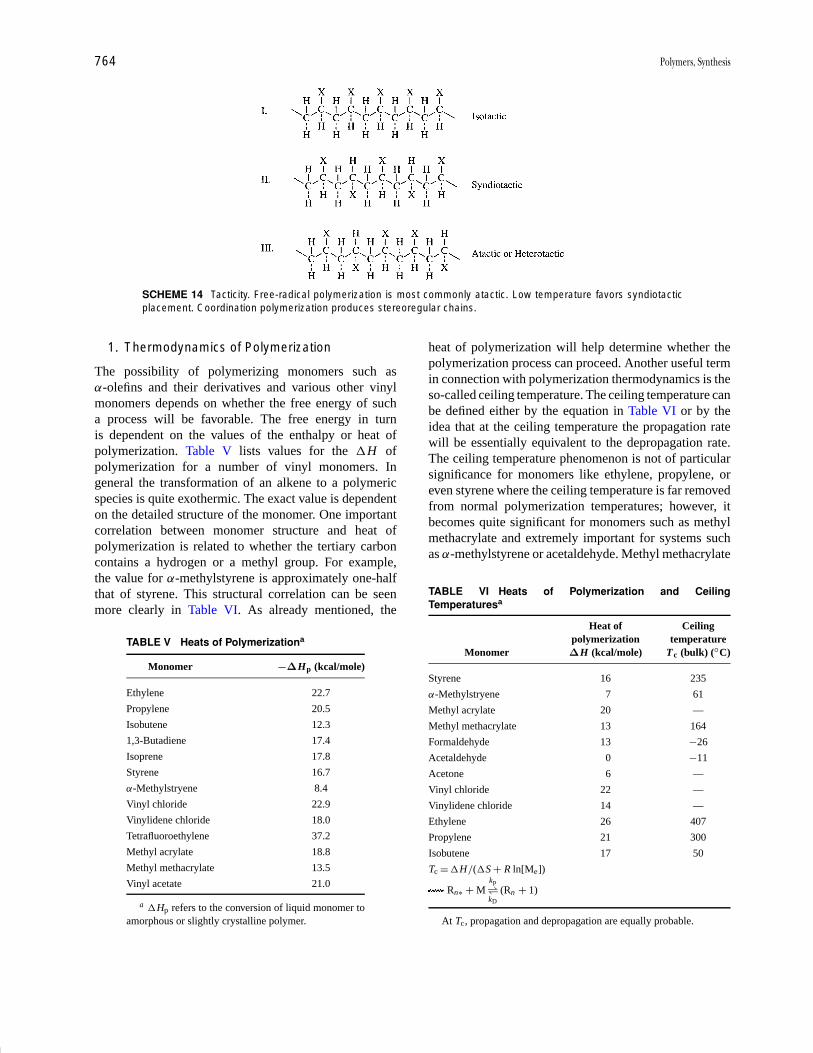
P1: GNH/GRI P2: GTV Final pages
Encyclopedia of Physical Science and Technology EN012B-596 July 27, 2001 18:18
764 Polymers, Synthesis
SCHEME 14 Tacticity. Free-radical polymerization is most commonly atactic. Low temperature favors syndiotacticplacement. Coordination polymerization produces stereoregular chains.
1. Thermodynamics of Polymerization
The possibility of polymerizing monomers such asα-olefins and their derivatives and various other vinylmonomers depends on whether the free energy of sucha process will be favorable. The free energy in turnis dependent on the values of the enthalpy or heat ofpolymerization. Table V lists values for the �H ofpolymerization for a number of vinyl monomers. Ingeneral the transformation of an alkene to a polymericspecies is quite exothermic. The exact value is dependenton the detailed structure of the monomer. One importantcorrelation between monomer structure and heat ofpolymerization is related to whether the tertiary carboncontains a hydrogen or a methyl group. For example,the value for α-methylstyrene is approximately one-halfthat of styrene. This structural correlation can be seenmore clearly in Table VI. As already mentioned, the
TABLE V Heats of Polymerizationa
Monomer −∆Hp (kcal/mole)
Ethylene 22.7
Propylene 20.5
Isobutene 12.3
1,3-Butadiene 17.4
Isoprene 17.8
Styrene 16.7
α-Methylstryene 8.4
Vinyl chloride 22.9
Vinylidene chloride 18.0
Tetrafluoroethylene 37.2
Methyl acrylate 18.8
Methyl methacrylate 13.5
Vinyl acetate 21.0
a �Hp refers to the conversion of liquid monomer toamorphous or slightly crystalline polymer.
heat of polymerization will help determine whether thepolymerization process can proceed. Another useful termin connection with polymerization thermodynamics is theso-called ceiling temperature. The ceiling temperature canbe defined either by the equation in Table VI or by theidea that at the ceiling temperature the propagation ratewill be essentially equivalent to the depropagation rate.The ceiling temperature phenomenon is not of particularsignificance for monomers like ethylene, propylene, oreven styrene where the ceiling temperature is far removedfrom normal polymerization temperatures; however, itbecomes quite significant for monomers such as methylmethacrylate and extremely important for systems suchas α-methylstyrene or acetaldehyde. Methyl methacrylate
TABLE VI Heats of Polymerization and CeilingTemperaturesa
Heat of Ceilingpolymerization temperature
Monomer ∆H (kcal/mole) Tc (bulk) (◦C)
Styrene 16 235
α-Methylstryene 7 61
Methyl acrylate 20 —
Methyl methacrylate 13 164
Formaldehyde 13 −26
Acetaldehyde 0 −11
Acetone 6 —
Vinyl chloride 22 —
Vinylidene chloride 14 —
Ethylene 26 407
Propylene 21 300
Isobutene 17 50
Tc = �H/(�S + R ln[Me])
Rn∗ + Mkp⇀↽kD
(Rn + 1)
At Tc, propagation and depropagation are equally probable.

P1: GNH/GRI P2: GTV Final pages
Encyclopedia of Physical Science and Technology EN012B-596 July 27, 2001 18:18
Polymers, Synthesis 765
can be easily polymerized to 1005% conversion. However,the ceiling temperature concept also has ramificationsfor polymer degradation. For example, if polymethylmethacrylate (PMMA) is exposed to free radicals athigh temperatures, one can basically unzip the polymerchain and regenerate nearly quantitatively the monomericspecies. The monomer α-methylstyrene has been widelystudied, and it is well known that it is very difficult topolymerize this structure to high molecular weight unlessone uses rather low temperatures. It is possible to use ananionic mechanism at −78◦C and completely polymerizeα-methylstyrene.
2. Kinetics of Free-Radical Polymerization
The propagation or the growth step involves the rapid ad-dition of additional monomer to the initiated species. Ifthis grows with a rate constant kp, where R now repre-sents a long chain, one can define the propagation reactionby the equation shown. An important assumption here isthat all the chains have the same reactivity. Another rea-sonable assumption is that the initiation step involves thereaction of only one monomer molecule and the propaga-tion involves the addition of many monomer molecules.The rate of the polymerization can be designated Rp andmay be shown to be basically equivalent to the rate ofpropagation. The rate of propagation or polymerization,then, will be given by the product of the rate constant kp,the monomer concentration, and the concentration of thegrowing species. Free radicals involve unpaired electrons,and hence their lifetime is rather short (e.g., a fractionof a second). Therefore, the growth step is basically atsome stage quickly terminated, usually by one of the twoschemes shown in Scheme 16. Some typical rate constantsare summarized in Table VII. Moreover, it is easy to seethat the termination rate constant is much faster than thatof either of the other two steps. This allows one to makea steady-state assumption in which one can set the rate ofinitiation equal to the rate of termination. An advantage ofdoing this is that it becomes possible to solve the equation
TABLE VII Typical Rate Constants
kI Low rate constant
kp ∼= 102–103 liters/mole sec
kT ∼= 107–109 liters/mole sec
Hence, a steady state of free radicals, e.g.,
RI = RT
2kd[I] = 2kt[M �]2
[M] =(
kd
kT[I]
)1/2
(difficult to measure)
Rp = kp
(kd
kT[I]
)1/2
[M]
shown in Table VII in terms of the radical concentration.On substituting this value into the rate expression, oneobtains a final rate expression that is quite useful. Basi-cally, it states that the rate of polymerization will dependon several constants, but that it will also be proportionalto the first power of the monomer concentration and tothe square root of the initiator concentration. Thus, asone doubles the initiator concentration, the expected ratedshould increase only by a factor of ∼1.4. If one plots therate of polymerization versus the log of the initiator con-centration for a variety of monomers and initiators suchas methyl methacrylate and AIBN or styrene and ben-zyl peroxide, for example, one observes slopes equal to1/2. An additional term in the rate of expression is f ,the fraction efficiency of initiation: For 100% efficiency,f has a value of 1.0. This is never achieved, although insome cases, particularly with some azo initiators, manypeople have reported values as high as 0.9. More recentwork has tended to indicate that this value may be ratherhigh.
A fourth process in polymerization kinetics is called thechain transfer reaction. This reaction is very important in avariety of cases, as outlined in Scheme 15. Here, we depicta growing chain interacting with a small molecule XYin such a way that a portion of the small molecule canterminate the active radical chain and at the same timeproduce a new radical Y. Basically, this step regulatesthe molecular weight. It does not necessarily decreasethe rate of polymerization if one assumes that thenew radical Y will again reinitiate more monomer and
SCHEME 15 Chain transfer.

P1: GNH/GRI P2: GTV Final pages
Encyclopedia of Physical Science and Technology EN012B-596 July 27, 2001 18:18
766 Polymers, Synthesis
the rate of polymerization can proceed basically asbefore.
There are many types of chain transfer steps, such astransfer to monomer, to a solvent, to an initiator, to a poly-mer, or even to a modifier. In all cases, the molecularweight will be decreased. The quantitative decrease willbe dependent on the reactivity of the growing macroradicalwith the small-molecule species. The extent to which thishappens is very dependent on the structure of the agent inquestion and can be roughly related to its reactivity witha small-molecule radical species. Some typical data areshown in Table VIII. An aromatic molecule, such as ben-zene, would not be expected to interact particularly effec-tively with radicals and, indeed, the chain transfer constanthere is rather small. On the other hand, molecules such ascarbon tetrachloride or certainly mercaptans have enor-mous activity with macroradicals and are very efficientchain transfer agents. One can assess the effectiveness ofa chain transfer agent by conducting polymerizations atvarious ratios of the chain transfer agent to the monomerand plotting the reciprocal of the number-average molecu-
SCHEME 16 Overview of free-radical kinetics.
TABLE VIII Chain Transfer Constants of VariousAgents to Styrene at 333 K
Agent 104CS
Benzene 0.023
n-Heptane 0.42
sec-Butylbenzene 6.22
m-Cresol 11.0
CCI4 90
CBr4 22,000
n-Butylmercaptan 210,000
lar weight or the number-average degree of polymerizationversus this ratio.
An overview of the kinetics of free-radical polymer-izations that takes into account chain transfer is providedin Scheme 16. Chain transfer to the polymer chain pro-duces a particular type of structure, namely, a branchedmacromolecule.
To this point, we have not discussed any detailed aspectof the polymerization process itself. There are essentially

P1: GNH/GRI P2: GTV Final pages
Encyclopedia of Physical Science and Technology EN012B-596 July 27, 2001 18:18
Polymers, Synthesis 767
TABLE IX Comparison of Homogeneous PolymerizationProcesses
Type Advantages Disadvantages
Bulk (batch type) Low impurity Thermal control difficultlevel
Casting possible
Bulk (continuous) Improved thermalcontrol
Solution Improved thermalcontrol
Isolation difficult
Requires devolatization
Difficult to remove solvent
Solvent recovery costly
Chain Transfer may limitmolecular weight
four important processes. First, one can have a bulk reac-tion in which basically only the monomer and possibly theintiator are used. Alternatively, a solution reaction processmay be used which has a monomer, initiator, and a sol-vent present. Bulk and solution reactions are sometimesreferred to as homogeneous processes. The other two pro-cesses are often termed heterogeneous processes, and theyare known as suspension and emulsion reactions. Severaladvantages and disadvantages of the various polymeriza-tion processes are given in Tables IX and X.
The bulk process has the advantage of allowing fora relatively low impurity level. Furthermore, it is pos-sible under some conditions to perform the polymeriza-tions discussed earlier. For example, some gasoline stationsigns are produced from cast polymethylmethacryalate(PMMA). One can imagine, however, that it would bevery difficult, if not impossible, to control the temperatureof such a reaction, recalling the heat of polymerization dis-cussed earlier. Moreover, the viscosity becomes enormousrather quickly, and one has to find a way to dissipate theheat of polymerization. The advantage of continuous pro-cesses is that in a series of reactions, for example, it maybe possible to achieve greater control of the temperature
TABLE X Comparison of Heterogeneous Polymerization Processes
Type Advantages Disadvantages
Suspension Low viscosity Highly sensitive to agitation rate
Simple polymer isolation Particle size difficult to control
Easy thermal control Possible contamination by suspending agent
May be of direct usable particle size Washing, drying, and compaction necessary
Emulsion Low viscosity Emulsifier, surfactants, and coagulants must be removed
Good thermal control High residual impurity level may degrade certain polymer properties
Latex may be directly usable High cost
100% conversion may be achieved Washing, drying, and compacting may be necessary
High MW possible at high rates
Small particle size product can be obtained
Operable with soft or tacky polymers
than in one bulk batch-type process. However, one proba-bly would still have to isolate the polymer by a relativelyhigh vacuum devolatilization step. This could be done andis done commercially, but nevertheless it might be con-sidered a disadvantage. In addition, a series of reactorsrequires one to design the engineering so as to be able torecycle monomer back to the first reaction for additionalpolymerization.
Conducting a solution process with an inert solvent cansolve several of these problems. This enables one to im-prove the thermal control and decrease the viscosity, butit is still difficult to remove quantitatively the solvent atthe end of this process. Moreover, the solvent may serveas a chain transfer agent, which will limit the molecu-lar weight to lower values than may be desired. In thesuspension processes, an agent such as polyvinyl alcoholor perhaps an inorganic oxide, such as zinc oxide, sta-bilizes the growing polymer particles and prevents themfrom coalescing together. The generation of particles thenessentially produces a relatively low viscosity particle sys-tem, which is desirable. If one converts all the monomer topolymer, then isolation becomes a fairly simple process offiltering off the finished polymer particles from the aque-ous media. Many important “glassy” polymers are madevia suspension processes; polystyrene and polyvinyl chlo-ride are made in this manner. On the negative side, it isnecessary to agitate very carefully, especially early in thereaction. Otherwise, the growing polymer particles mightaggregate rather than stay in discrete small particles. Atthe end of the reaction, one has to accept the fact thatthe polymer will contain a small residual amount of thesuspending agent.
In emulsion reactions, as in the suspension case, wa-ter is the heat transfer medium and hence it is easy toobtain good thermal control. Very small particle sizes ofthe order of a few hundred to a few thousand angstromscan be obtained. In emulsion polymerization, surfactants,
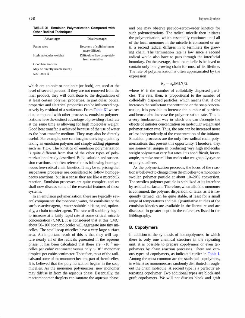
P1: GNH/GRI P2: GTV Final pages
Encyclopedia of Physical Science and Technology EN012B-596 July 27, 2001 18:18
768 Polymers, Synthesis
TABLE XI Emulsion Polymerization Compared withOther Radical Techniques
Advantages Disadvantages
Faster rates Recovery of solid polymermore difficult
High molecular weights Difficult to free completelyfrom emulsifier
Good heat transfer
May be directly usable (latex)
500–5000 A
which are anionic or nonionic (or both), are used at thelevel of several percent. If they are not removed from thefinal product, they will contribute to the degradation ofat least certain polymer properties. In particular, opticalproperties and electrical properties can be influenced neg-atively by residual of a surfactant. From Table XI we seethat, compared with other processes, emulsion polymer-izations have the distinct advantage of providing a fast rateat the same time as allowing for high molecular weight.Good heat transfer is achieved because of the use of wateras the heat transfer medium. They may also be directlyuseful. For example, one can imagine deriving a paint bytaking an emulsion polymer and simply adding pigmentssuch as TiO2. The kinetics of emulsion polymerizationis quite different from that of the other types of poly-merization already described. Bulk, solution and suspen-sion reactions are often referred to as following homoge-neous free-radical chain kinetics. It may be surprising thatsuspension processes are considered to follow homoge-neous reactions, but in a sense they are like a microbulkreaction. Emulsion processes are quite complex, and weshall now discuss some of the essential features of thesesystems.
In an emulsion polymerization, there are typically sev-eral components: the monomer, water, the emulsifier or thesurface-active agent, a water-soluble initiator, and, option-ally, a chain transfer agent. The rate will suddenly beginto increase at a fairly rapid rate at some critical micelleconcentration (CMC). It is considered that at this CMC,about 50–100 soap molecules will aggregate into tiny mi-celles. The small soap micelles have a very large surfacearea. An important result of this is that they will cap-ture nearly all of the radicals generated in the aqueousphase. It has been calculated that there are ∼1018 mi-celles per cubic centimeter versus only ∼1011 monomerdroplets per cubic centimeter. Therefore, most of the radi-cals and some of the monomer become part of the micelles.It is believed that the polymerization begins in the soapmicelles. As the monomer polymerizes, new monomermay diffuse in from the aqueous phase. Essentially, themacromonomer droplets can saturate the aqueous phase,
and one may observe pseudo-zeroth-order kinetics forsuch polymerizations. The radical micelle then initiatesthe polymerization, which essentially continues until allof the local monomer in the micelle is consumed or un-til a second radical diffuses in to terminate the grow-ing chain. The termination rate is low since a secondradical would also have to pass through the interfacialboundary. On the average, then, the micelle is believed tocontain only one growing chain for most of its lifetime.The rate of polymerization is often approximated by theexpression
Rp = kp[M]N /2,
where N is the number of colloidally dispersed parti-cles. The rate, then, is proportional to the number ofcolloidally dispersed particles, which means that, if oneincreases the surfactant concentration or the soap concen-tration, it is possible to increase the number of particlesand hence also increase the polymerization rate. This isa very fundamental way in which one can decouple theeffects of initiator concentration on molecular weight andpolymerization rate. Thus, the rate can be increased moreor less independently of the concentration of the initiator.Emulsion processes are the only free-radical chain poly-merizations that present this opportunity. Therefore, theyare somewhat unique in producing very high molecularweight polymers at very fast rates. It is not difficult, for ex-ample, to make one million-molecular weight polystyreneor polybutadiene.
As the polymerization proceeds, the locus of the reac-tion is believed to change from the micelles to a monomer-swollen polymer particle at about 10–20% conversion.The swollen polymer particle is stabilized at its interfaceby residual surfactant. Therefore, when all of the monomeris consumed, the polymer dispersion, or latex, as it is fre-quently termed, can be quite stable, at least for a smallrange of temperatures and pH. Quantitative studies of theemulsion kinetics are available in the literature and arediscussed in greater depth in the references listed in theBibliography.
B. Copolymers
In addition to the synthesis of homopolymers, in whichthere is only one chemical structure in the repeatingunit, it is possible to prepare copolymers or even ter-polymers by chain reaction processes. There are vari-ous types of copolymers, as indicated earlier in Table I.Among the most common are the statistical copolymers,in which two monomers are randomly distributed through-out the chain molecule. A second type is a perfectly al-ternating copolymer. Two additional types are block andgraft copolymers. We will not discuss block and graft
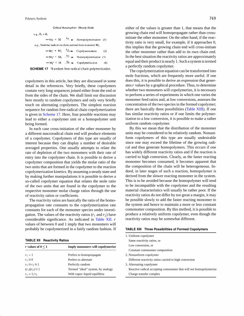
P1: GNH/GRI P2: GTV Final pages
Encyclopedia of Physical Science and Technology EN012B-596 July 27, 2001 18:18
Polymers, Synthesis 769
SCHEME 17 “Random free-radical chain polymerization.
copolymers in this article, but they are discussed in somedetail in the references. Very briefly, these copolymerscontain very long sequences joined either from the end orfrom the sides of the chain. We shall limit our discussionhere mostly to random copolymers and only very brieflytouch on alternating copolymers. The simplest reactionsequence for random free-radical chain copolymerizationis given in Scheme 17. Here, four possible reactions maylead to either a copolymer unit or a homopolymer unitbeing formed.
In each case cross-initiation of the other monomer bya different macroradical chain end will produce elementsof a copolymer. Copolymers of this type are usually ofinterest because they can display a number of desirableaveraged properties. One usually attempts to relate therate of depletion of the two monomers with their rate ofentry into the copolymer chain. It is possible to derive acopolymer composition that yields the molar ratio of thetwo units that are formed in the copolymer to the reactioncopolymerization kinetics. By assuming a steady state andby making further manipulations it is possible to derive aso-called copolymer equation that relates the mole ratioof the two units that are found in the copolymer to therespective monomer molar charge ratios through the useof reactivity ratios or coefficients.
The reactivity ratios are basically the ratio of the homo-propagation rate constants to the copolymerization rateconstants for each of the monomer species under investi-gation. The values of the reactivity ratios (r1 and r2) haveconsiderable significance. As indicated in Table XII. rvalues of between 0 and 1 imply that two monomers willprobably be copolymerized in a fairly random fashion. If
TABLE XII Reactivity Ratios
r values of 0 ≤ 1 Imply monomers will copolymerize
r1 > 1 Prefers to homopropagate
r1 ∼= 0 Prefers to alternate
r1 ∼= r2 ∼= 1 Perfectly random
(r1)(r2) ∼= 1 Termed “ideal” system, by analogy
r1 = 1/r2 With vapor–liquid equilibria
either of the values is greater than 1, that means that thegrowing chain end will homopropagate rather than cross-initiate the other monomer. On the other hand, if the reac-tivity ratio is very small, for example, if it approaches 0,this implies that the growing chain end will cross-initiatethe other monomer rather than add to its own chain end.In the best situation the reactivity ratios are approximatelyequal and their product is nearly 1. Such a system is termeda perfectly random copolymer.
The copolymerization equation can be transformed intomole fractions, which are frequently more useful. If onedoes this, it is possible to derive an expression that gener-ates r values by a graphical procedure. Thus, to determinewhether two monomers will copolymerize, it is necessaryto perform a series of experiments in which one varies themonomer feed ratios and, at low conversions, assesses theconcentration of the two species in the formed copolymer;there are basically three possibilities (Table XIII). If onehas similar reactivity ratios or if one limits the polymer-ization to a low conversion, it is possible to make a ratheruniform random copolymer.
By this we mean that the distribution of the monomerunits may be considered to be relatively random. Nonuni-form copolymers of this type are usually undesirablesince one may exceed the lifetime of the growing radi-cal and thus generate homopolymers. This occurs if onehas widely different reactivity ratios and if the reaction iscarried to high conversion. Clearly, as the faster reactingmonomer becomes consumed, it becomes apparent thatthe composition of the chain will be heterogeneous. In-deed, in later stages of such a reaction, homopolymer isderived from the slower reacting monomer in the system.This is to be avoided because the homopolymer will tendto be incompatible with the copolymer and the resultingmaterial characteristics will usually be rather poor. If thereactivity ratios do not differ by too great a margin, it maybe possible slowly to add the faster reacting monomer tothe system and hence to maintain a more or less constantcomonomer composition. By this method, it is possible toproduce a relatively uniform copolymer, even though thereactivity ratios may be somewhat different.
TABLE XIII Three Possibilities of Formed Copolymers
1. Uniform copolymer
Same reactivity ratios, or
Low conversion, or
Constant comonomer composition
2. Nonuniform copolymer
Different reactivity ratios carried to high conversion
3. Alternating copolymer
Reactive radical accepting comonomer that will not homopolymerize
Charge transfer complex
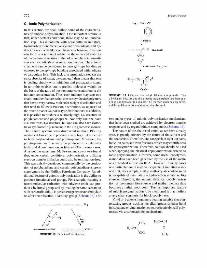
P1: GNH/GRI P2: GTV Final pages
Encyclopedia of Physical Science and Technology EN012B-596 July 27, 2001 18:18
770 Polymers, Synthesis
C. Ionic Polymerization
In this section, we shall outline some of the characteris-tics of anionic polymerization. One important feature isthat, under certain conditions, there may be no termina-tion step. This is possible with organolithium initiators,hydrocarbon monomers like styrene or butadiene, and hy-drocarbon solvents like cyclohexane or benzene. The rea-son for this is no doubt related to the enhanced stabilityof the carbanion relative to that of other chain intermedi-ates such as radicals or even carbonium ions. The anionicchain end can be considered to have sp3-type bonding asopposed to the sp2-type bonding associated with radicalsor carbonium ions. This lack of a termination step (in thestrict absence of water, oxygen, etc.) then means that oneis dealing simply with initiation and propagation steps.In turn, this enables one to predict molecular weight onthe basis of the ratio of the monomer concentration to theinitiator concentration. Thus, each initiator may start onechain. Another feature is that one can synthesize polymersthat have a very narrow molecular weight distribution andthat tend to follow a Poisson distribution, as opposed tothe much broader Gaussian-type distributions. In addition,it is possible to produce a relatively high 1,4 structure inpolybutadiene and polyisoprene. Not only can one havecis- and trans-1,4 structure, but one can also have isotac-tic or syndiotactic placement in the 1,2 geometric isomer.The lithium systems were discovered in about 1955 byworkers at Firestone to produce a very high 1,4 structurein both polybutadiene and polyisoprene. Moreover, thepolyisoprene could actually be produced in a relativelyhigh cis-1,4 configuration, as high as 93% in some cases.At about the same time, M. Szwarc and coworkers foundthat, under certain conditions, polymerizations utilizingelectron transfer initiation could also be termination-free.This was quickly developed commercially by the produc-tion of polybutadiene and certain polybutadiene–styrenecopolymers by the Phillips Petroleum Company. An ad-ditional feature of anionic polymerization is the ability toproduce functional end groups. For example, reacting amacromolecular carbanion with ethylene oxide can pro-duce a hydroxyl group, and by treating the same carbanionwith carbon dioxide, it is possible to generate a carboxylateor, after neutralization, a carboxyl group (Scheme 18). The
SCHEME 18 Functional termination.
SCHEME 19 Initiation via alkyl lithium compounds. Thealkyllithium initiator and the growing polymerchain are homoge-neous and hydrocarbon soluble. The reaction proceeds via nucle-ophilic addition to the unsaturated double bond.
two major types of anionic polymerization mechanismsthat have been studied are achieved by electron transferreagents and by organolithium compounds (Scheme 19).
The nature of the chain end anion, as we have alreadyseen, is greatly affected by the nature of the solvent andthe counterion. Therefore, one can speak of tight ion pairs,loose ion pairs, and even free ions, which may contribute tothe copolymerization. Therefore, caution should be usedwhen applying the classical copolymerization criteria toionic polymerization. However, some useful copolymer-ization data have been generated by the use of the meth-ods described in Section III.A. However, in many casesone particular anion may be incapable of initiating a sec-ond unit. For example, methyl methacrylate enolate anionis incapable of reinitiating a hydrocarbon monomer likestyrene. Therefore, the anionic statistical copolymeriza-tion of monomers like styrene and methyl methacrylatebecomes a rather moot point. The last important featureof anionic polymerization to be mentioned is that it offersa very clean synthesis for block copolymers.
Vinyl or 1-alkene monomers bearing suitable electron-releasing groups, such as the alkyl groups or ether bondin isobutene or vinyl methyl ether, respectively, will poly-merize via a carbocationic mechanism:
CH3/
H2C C\CH3
H2C CH|O|
CH3

P1: GNH/GRI P2: GTV Final pages
Encyclopedia of Physical Science and Technology EN012B-596 July 27, 2001 18:18
Polymers, Synthesis 771
The electron enrichment may occur by either inductiveor resonance routes. Moreover, numerous heteroatom-containing cyclic monomers, such as
n(CH2) X X O, S, N, etc.�
can also be polymerized via positively charged species(e.g., oxonium ions).
The reactive growing chain end will have much sp2-type character in the case of carbocationic polymeriza-tions. Thus, it should not be surprising that these chainreactions have much shorter lifetimes than the previouslydiscussed anionic systems. The carbocationic chain endhas traditionally been referred to as a carbonium ion. How-ever, may workers in the polymerization field now preferthe term carbenium ion as a better choice for a trigonal,trivalent sp2-hybridized species.
Carbocationic polymerizations of 1-alkenes can be ini-tiated by a variety of homogeneous or heterogeneousLewis acids,
RCl � AlCl3 R�(AlCl4)�
� BF3 H2O BF3HOH
� H2CH2O BF3 C(CH3)2 H3C C�(BF3OH)�
(CH3)2
such as BF3, TiCl4, AlCl3, and Al(C2H5)2Cl. The processis somewhat analogous to reactions such as alkylations thatare very familiar to organic chemists. The reactions mayrequire that either a proton donor (e.g., water) or cationdonor (e.g., a tertiary halide) be present. Thus, isobuteneis inert in the presence of BF3 if the system is rigorouslydry. Reaction will begin immediately if catalytic quantitiesof, say tert-butyl halide or water are added. The initiationmechanism may be quite complex. However, J. P. Kennedyand colleagues demonstrated that the chain end (“HEAD”group) formed in the presence of cation donors is, in fact,derived from the cation. Thus, they consider the proton orcation source to be the initiator and the Lewis acid to serveas the coinitiator.
An overview of the carbocationic polymerization isgiven in Scheme 20. One major difficulty with manycationic polymerizations is that many other chain trans-fer or chain-breaking reactions can effectively competewith the chain growth step. Carbonium (carbenium) ionscan undergo many reactions such as alkylation, isomeriza-tion, and so on. In a carbocationic polymerization thesereactions have the net result of lowering the molecularweight, often to lower than desired values. Fortunately,one may “freeze out” many of these events by loweringthe polymerization temperature. Thus, poly(isobutene) or
SCHEME 20 Mechanism of carbenium ion polymeriza-tion. Often low temperature is required to achieve highmolecular weights. Controlled end groups can be provided.
butyl rubber (a copolymer with a small amount of iso-prene) is probably produced commercially at −40◦C orlower:
CH2 C CH2 C CH CH2
CH3
CH3
CH3
Butyl rubber
Carbocationic polymerizations may also be used to poly-merize other alkenes such as propylene or styrene to mod-erately high molecular weight. However, these polymer-izations are not stereoregular and the commercial utilityhas been quite limited.
The advent of Ziegler–Natta catalysis in the mid-1950samplified and greatly expanded the idea that ionic poly-merizations can be stereochemically controlled via coor-dination of the growing chain end with its monomer andcounterion. The industrial importance of these reactionsis apparent from the fact that coordination polymeriza-tion is used to produce linear (high-density) polyethy-lene (HDPE), linear low-density polyethylene (LLDPE),isotactic polypropylene, isotactic poly(1-butene), variousethylene–propylene co- and terpolymers, cis-1,4-poly-butadiene, and cis-1,4-polyisoprene. The volume of theseimportant rubbers and plastics probably exceeds that ofpolymeric materials produce by all other chain (or step-growth) processes. K. Ziegler and G. Natta received theNobel Prize in 1963 for their contributions.
The components of a Ziegler–Natta catalyst are listed inTable XIV. The utilization of these usually heterogeneouscatalysis is well developed. However, because of the enor-mous complexities, mechanistic understanding has beenrelatively slow to evolve. One should also note that the cat-alysts may themselves also be deposited on supports such

P1: GNH/GRI P2: GTV Final pages
Encyclopedia of Physical Science and Technology EN012B-596 July 27, 2001 18:18
772 Polymers, Synthesis
TABLE XIV Typical Ziegler–Natta Catalyst Components
Transition metal halide [Me(I)]
TiX4, TiX3, VX4, VX3, VOX3
Co, Ni complexes
Organometallic compound [Me(II)]
AIR3, AIR2X, ZnR2, LiR, etc.
Generally agreed
Mi(II) alkylates, reduces Me(I)
Alkylated Me(I) responsible for chain growth
AIEt3 + TiCl4 → TiCl3Et + AlEt2Cl
TiCl3Et → TiCl3 + Et
AlEt3 + TiCl3 → TiCl2R + AlEt2Cl
Cl2TiR + x(monomer) → Cl2Ti(monomer)x R
as silica or alumina. The most generally accepted mecha-nism is shown in Scheme 21. Although free radicals canbe produced, they are not involved in these types of poly-merizations. The olefin is believed to coordinate first viaπ bonding with vacant d orbitals in the transition metalcomplex. The availability and stability of these coordi-nation sites can be influenced significantly by the metalalkyl. Nevertheless, it is usually now considered to be amonometallic mechanism. The coordination species mustundergo a cis rearrangement both to yield the stereoregu-lar placement and to produce a new vacancy in the transi-tion metal structure, which may coordinate with the nextmonomer unit (the propagation step).
Most of the industrial interest has centered on 1-alkenes, dienes, or ethylene polymerizations. Many othermonomers, such as methyl methacrylate and vinyl alkylethers, have also been studied. Heteroatom-containingmonomers have further sites for coordination and hencecan yield stereospecific polymerizations under even
SCHEME 21 Evolution of ideas on the mechanism of olefin co-ordination polymerization. The essential steps are as follows. Anoctahedral titanium complex has a chlorine vacancy. Alkylation oc-curs, giving an alkylated titanium species that still has a chlorinevacancy. Monomer is adsorbed on the vacancy and is π -bondedto the titanium atom. A “cis migration” occurs, leading to a newtitanium-carbon bond.
“homogeneous” conditions. This enormously importantmechanism remains an active area of research.
The process of transforming a heteroatom-containingring to a linear chain is often described as a ring-openingpolymerization:
nM (CH2) X CH2( (
Xn
(
m
This process almost always involves anionic, cationic, orcoordination initiation (catalysis). Only in very specialsituations have free-radical initiators been successful.
Some major types of cyclic monomers that undergoring-opening reactions are shown in Table XV. Thethermodynamic feasibility of such a process for cyclicethers as a function of ring size is shown in Table XVI. Forsmall rings such as ethylene oxide, the reaction is highlyexothermic, and polymerization proceeds with eitheranionic or cationic initiators. Dioxane has not been poly-merized. Larger cyclic ethers such as tetrahydrofuran areinitiated only by oxonium salts such as (C2H5)3O+(BF4)−.Presumably, the oxonium salt initiates by coordinationwith the electron pair of the cyclic ether. Propagation then
TABLE XV Some Important Examples of Ring-OpeningPolymerization
Cyclic monomer Ring-opening reaction
Ethers
C C
OCH2 CH2 O
n
Acetals
C CCH2 O
n
O
O OC
Esters (lactones)
(CH2)5
O (CH2)5n
C
O
O C
O
Amides (lactams)
(CH2)5
(CH2)5n
C
O
HN C
OH
N
Siloxanes
SiSi O
O
O OSi
Si
CH3
CH3
n
Phosphazines
P N
Cl
Cl
nP N
Cl
Cl
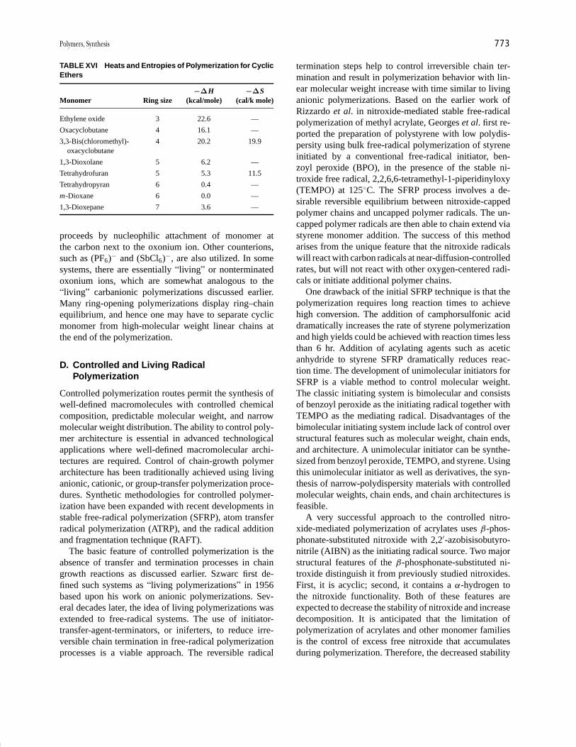
P1: GNH/GRI P2: GTV Final pages
Encyclopedia of Physical Science and Technology EN012B-596 July 27, 2001 18:18
Polymers, Synthesis 773
TABLE XVI Heats and Entropies of Polymerization for CyclicEthers
−∆H −∆SMonomer Ring size (kcal/mole) (cal/k mole)
Ethylene oxide 3 22.6 —
Oxacyclobutane 4 16.1 —
3,3-Bis(chloromethyl)- 4 20.2 19.9oxacyclobutane
1,3-Dioxolane 5 6.2 —
Tetrahydrofuran 5 5.3 11.5
Tetrahydropyran 6 0.4 —
m-Dioxane 6 0.0 —
1,3-Dioxepane 7 3.6 —
proceeds by nucleophilic attachment of monomer atthe carbon next to the oxonium ion. Other counterions,such as (PF6)− and (SbCl6)−, are also utilized. In somesystems, there are essentially “living” or nonterminatedoxonium ions, which are somewhat analogous to the“living” carbanionic polymerizations discussed earlier.Many ring-opening polymerizations display ring–chainequilibrium, and hence one may have to separate cyclicmonomer from high-molecular weight linear chains atthe end of the polymerization.
D. Controlled and Living RadicalPolymerization
Controlled polymerization routes permit the synthesis ofwell-defined macromolecules with controlled chemicalcomposition, predictable molecular weight, and narrowmolecular weight distribution. The ability to control poly-mer architecture is essential in advanced technologicalapplications where well-defined macromolecular archi-tectures are required. Control of chain-growth polymerarchitecture has been traditionally achieved using livinganionic, cationic, or group-transfer polymerization proce-dures. Synthetic methodologies for controlled polymer-ization have been expanded with recent developments instable free-radical polymerization (SFRP), atom transferradical polymerization (ATRP), and the radical additionand fragmentation technique (RAFT).
The basic feature of controlled polymerization is theabsence of transfer and termination processes in chaingrowth reactions as discussed earlier. Szwarc first de-fined such systems as “living polymerizations” in 1956based upon his work on anionic polymerizations. Sev-eral decades later, the idea of living polymerizations wasextended to free-radical systems. The use of initiator-transfer-agent-terminators, or iniferters, to reduce irre-versible chain termination in free-radical polymerizationprocesses is a viable approach. The reversible radical
termination steps help to control irreversible chain ter-mination and result in polymerization behavior with lin-ear molecular weight increase with time similar to livinganionic polymerizations. Based on the earlier work ofRizzardo et al. in nitroxide-mediated stable free-radicalpolymerization of methyl acrylate, Georges et al. first re-ported the preparation of polystyrene with low polydis-persity using bulk free-radical polymerization of styreneinitiated by a conventional free-radical initiator, ben-zoyl peroxide (BPO), in the presence of the stable ni-troxide free radical, 2,2,6,6-tetramethyl-1-piperidinyloxy(TEMPO) at 125◦C. The SFRP process involves a de-sirable reversible equilibrium between nitroxide-cappedpolymer chains and uncapped polymer radicals. The un-capped polymer radicals are then able to chain extend viastyrene monomer addition. The success of this methodarises from the unique feature that the nitroxide radicalswill react with carbon radicals at near-diffusion-controlledrates, but will not react with other oxygen-centered radi-cals or initiate additional polymer chains.
One drawback of the initial SFRP technique is that thepolymerization requires long reaction times to achievehigh conversion. The addition of camphorsulfonic aciddramatically increases the rate of styrene polymerizationand high yields could be achieved with reaction times lessthan 6 hr. Addition of acylating agents such as aceticanhydride to styrene SFRP dramatically reduces reac-tion time. The development of unimolecular initiators forSFRP is a viable method to control molecular weight.The classic initiating system is bimolecular and consistsof benzoyl peroxide as the initiating radical together withTEMPO as the mediating radical. Disadvantages of thebimolecular initiating system include lack of control overstructural features such as molecular weight, chain ends,and architecture. A unimolecular initiator can be synthe-sized from benzoyl peroxide, TEMPO, and styrene. Usingthis unimolecular initiator as well as derivatives, the syn-thesis of narrow-polydispersity materials with controlledmolecular weights, chain ends, and chain architectures isfeasible.
A very successful approach to the controlled nitro-xide-mediated polymerization of acrylates uses β-phos-phonate-substituted nitroxide with 2,2′-azobisisobutyro-nitrile (AIBN) as the initiating radical source. Two majorstructural features of the β-phosphonate-substituted ni-troxide distinguish it from previously studied nitroxides.First, it is acyclic; second, it contains a α-hydrogen tothe nitroxide functionality. Both of these features areexpected to decrease the stability of nitroxide and increasedecomposition. It is anticipated that the limitation ofpolymerization of acrylates and other monomer familiesis the control of excess free nitroxide that accumulatesduring polymerization. Therefore, the decreased stability
P1: GNH/GRI P2: GTV Final pages
Encyclopedia of Physical Science and Technology EN012B-596 July 27, 2001 18:18
774 Polymers, Synthesis
of the acyclic β-phosphonate-substituted nitroxide bear-ing a α-hydrogen leads to decreased accumulation ofexcess nitroxide during reaction and results in improvedcontrol over the polymerization of acrylates. Severalacyclic α-hydrogen-bearing alkoxyamines were foundto be successful for the controlled polymerization ofboth styrene and acrylates. Two structures in particularhave been found to be very robust and successfullypolymerized styrene: they are acrylate-, acrylamide-, andacrylonitrile-based monomers with controlled molecularweights from 1000 to 200,000 g/mole and polydispersitiesof 1.05 to 1.15. Hawker also reported the synthesis ofnarrow-polydispersity block and random copolymersbased on combinations of the above monomers.
SEE ALSO THE FOLLOWING ARTICLES
CATALYSIS, INDUSTRIAL • MACROMOLECULES, STRUC-TURE • ORGANIC CHEMISTRY, SYNTHESIS • POLYMERS,RECYCLING • POLYMERS, THERMALLY STABLE
BIBLIOGRAPHY
Bhanu, V. A., and Kishare, K. (1991). Chem Rev. 91(2), 99–118.Colombani, D. (1997). “Chain growth control in free radical polymer-
izations,” Prog. Polym. Sci. 22(8), 1649–1720.Culbertson, B. M., and McGrath, J. E. (eds.). (1985). “Advances in Poly-
mer Synthesis,” Vol. 31, Plenum Press, New York.
Ferguson, J. (1984). “Step growth polymerization. Part 1. Polyesters,polycarbonates, polyamides, and polyimides,” Macromol. Chem. 3,76–92.
Heitz, W. (1995). “Metal-catalyzed polycondensation reactions,” PureAppl. Chem. 67(12), 1951–1964.
Hogen-Esch, T., and Smid, J. (eds.). (1987). “Recent Advances in An-ionic Polymerization,” Elsevier, New York.
Kendall, J. L., Canelas, D. A., Young, J. L., and DeSimone, J. M. (1999).“Polymerizations in supercritical carbon dioxide,” Chem. Rev. 99(2),543–563.
Labadie, J. W., Hedrick, J. L., and Ueda, M. (1996). “A survey of somerecent advances in step-growth polymerizations,” ACS Symp. Ser. 624,294–305.
Long, T. E., and Turner, S. R. (2000). “Step growth polymerization,”In “Applied Polymer Science 21st century (2000)” (C. D. Craver andC. E. Carraher, eds.), pp. 979–998, Elsevier, New York.
Nuyken, O., and Pask, S. (1989). “Telechelic polymers,” In “Encyclo-pedia of Polymer Science and Engineering” (J. J. Kroschwitz, ed.),Vol. 16, pp. 494–532, Wiley, New York.
Odian, G. (1985). “Chain-reaction polymerization. In “Encyclopedia ofPolymer Science and Engineering” (J. J. Kroschwitz, ed.), Vol. 3,pp. 247–288, Wiley, New York.
Sparrow, D. J., and Walton, I. G. (1984). “Step growth polymeriza-tions, Part II. Developments in polyurethanes,” Macromol. Chem. 3,93–97.
Tirrell, D. A. (1985). “Copolymerization,” In “Encyclopedia of PolymerScience and Engineering” (J. J. Kroschwitz, ed.), Vol. 4, pp. 192–233,Wiley, New York.
Turner, S. R. (1999). “Historical development and progress in stepgrowth polymerization,” Polym. Mater. Sci. Eng. 80, 285.
Wagener, K. B., and Davidson, T. A. (1996). “Non-conjugated andconjugated dienes in acrylic diene metathesis (ADMET) chem-istry,” In “New Macromolecular Architecture and Functions. Proceed-ings OUMS ’95” (M. Kamachi and A. Nakamura, eds.,) Springer,Berlin.

P1: GPQ Final Pages/GNB P2: GTV Qu: 00, 00, 00, 00
Encyclopedia of Physical Science and Technology En012c-604 July 26, 2001 16:2
Polymers, Thermally StableJ. P. CritchleyRoyal Aerospace Establishment
I. Thermally Stable PolymersII. Carbocyclic Aromatic Systems
III. Heterocyclic Aromatic (Heteroaromatic) Systems
GLOSSARY
Ablative coating Polymeric material providing thermalprotection whereby high levels of heat flux are absorbedin the course of the pyrolytic thermal decomposition ofthe exposed surface layer.
Creep (cold flow) Reversible change in shape sustainedby thermoplastic materials under sustained loading.
Cross-linking Formation of three-dimensional or net-work polymer systems by polymerization of monomerswith functionality greater than two or by covalent bond-ing between preformed linear molecules.
Cyclopolycondensation Process in which a stable hete-rocyclic ring is formed as part of the polymer chainbackbone with elimination of condensation volatiles.The process can occur via chain extension or postpoly-merization of a preformed precursor polymer.
Interlaminar shear strength (ILSS) Design critical fea-ture of fiber-reinforced composites relating to the ab-solute stress level required to separate individual layersof reinforcement. For optimum levels of fiber strengthand loading a valuable analytic tool for predicting com-pressive and flexural strengths of individual compositesformulated from different resin matrices.
Interpenetrating network system (IPN) An intimatemixture of two or more polymeric networks held to-gether predominantly by permanent entanglements.
These entanglements restrict the segmental motionsuch that the creep and flow phenomena of the par-ticipating polymers can be radically reduced.
Ladder (double-strand) systems Relates to linear as op-posed to network polymers in which two molecularstrands are linked often via complex ring systems. “Per-fect” ladder polymers require the rupture of at least twobonds within the same ring before major reduction inmolecular weight can occur.
Liquid crystallinity Is exhibited in melt (thermotropism)or solution (lyotropism) by polymers having rigid rod-like structures; such polymers showing spontaneousanisotropy and readily induced orientation in the liquidcrystalline state. Processing (i.e., fiber spinning) fromthis state can lead to materials with great strength inthe direction of orientation.
Molecular composites Utilize the extended chain struc-ture of a rigid-rod segment as reinforcement, copoly-merized or blended at molecular level with the flexiblematrix component which may be, typically, a thermo-plastic polymer. To achieve optimum properties for thecomposite, there should be little or no phase separationbetween rigid-rod and matrix components.
Polymer degradation Involves the chemical modifica-tion of main-chain backbone and/or side groups of themacromolecule. The process requires rupture of pri-mary valence bonds and results in reduced molecular
775

P1: GPQ Final Pages/GNB P2: GTV
Encyclopedia of Physical Science and Technology En012c-604 July 26, 2001 16:2
776 Polymers, Thermally Stable
weight, cross-linking, or cyclization. As a general crite-rion, degradation adversely affects those polymer prop-erties critical for commercially viable plastics, fibers,or rubbers.
Reinforced plastics Composite nonmetallic materials forwhich the basic resin system is combined in varyingproportion with a fibrous additive in order to improvethe mechanical strength and modulus of the matrix.
Rigid-rod polymers Formed from benzenoid and hetero-cyclic moieties, the molecules are colinearly arrangedand have rotational flexibility within the polymer back-bone only at the junction of phenyl and heterocyclicrings.
Thermal analysis Measurement and evaluation of poly-mer thermal stability by monitoring a specific polymerproperty with respect to temperature. Analytic data in-cludes polymer weight loss measured by dynamic orisothermal thermogravimetric analysis (TGA); glasstransition temperature (Tg) measured calorimetricallyby differential scanning calorimetry (DSC)/differentialthermal analysis (DTA) or mechanically by tor-sional braid analysis (TBA)/thermomechanical analy-sis (TMA); monitoring volatile by-products by effluentgas analysis (EGA).
Thermoplastic polymer Relates to a plastic material thatcan be repeatedly softened when heated and hardenedwhen cooled.
Thermosetting resin Polymer capable of being modifiedinto a predominantly and permanently infusible and in-soluble material due to the effects of heat or chemicalprocesses.
THE KEY Requirement for a successful “working” ther-mally stable (heat-resistant) polymer is that function-ing within clearly defined parameters of temperature,time, and environment it should retain a high propor-tion of those practically useful properties in material form(e.g., film, fiber, resin matrix, or metal-to-metal adhesive)that were demonstrated under ambient conditions. Thetemperature–time limitations most frequently imposed in-clude 230–260◦C for several thousand hours, 360–370◦Cfor hundreds of hours, 550–560◦C for 1 hr, and 750–800◦C (ablative conditions) for minutes only. The envi-ronment within which the polymer must function willinclude the prevailing atmosphere surrounding the poly-mer (inert gas, air/oxygen, or vacuum), possible exposureto chemical attack and/or radiation, and the individualor combined mechanical stress factors (tensile, compres-sive, shear) encountered under static or dynamic loadingconditions.
The 1990s saw significant changes in the direction takenby developments in the field of thermally stable materials,
away from an emphasis on predominantly military ap-plications into aspects of multidisciplinary studies. Thus,while research into high-temperature polymers has contin-ued to be directed toward aerospace requirements, therehas also been a move toward environmental objectives,which has led, for example, to studies into dielectricsfor electronic applications, polymer sensors, resist materi-als, and polymeric membranes. Associated basic studies,while continuing to examine the design and synthesis ofthermally stable systems, have concentrated efforts intothose areas of polymer chemistry linked to chain architec-ture and the control of end-group structure. The previousoverriding emphasis on stability, both thermal and thermo-oxidative, which frequently led to brittle “brick dusts,” hasshifted noticeably toward efforts to provide an optimumthermal/thermo-oxidative stability allied with a capacityto produce processible materials that can provide manu-factured products (see Section 1.C) by melt, solution, ordispersion processing.
I. THERMALLY STABLE POLYMERS
A. Essentials of Polymer Stability
Two basic mechanisms control property deterioration ofpolymers at elevated temperature. One, linked predom-inantly to thermoplastics, involves a reversible whollytemperature-dependent softening phenomenon; the otheran irreversible degradative process time, temperature, andenvironment dependent relates to thermosets.
To increase the polymer softening point, or more criti-cally the glass transition temperature (Tg), it is necessaryto maximize contributions from both interchain attractiveforces and chain regularity:
Interchain forces Chain regularity
Polar side groups Crystallinity
Hydrogen bonding para-Linked cyclics
Cross-linking Extensive orientation
Observations from the purely thermal degradation ofseveral polymers with closely related structures have em-phasized the following features as important for high ther-mal stability:
1. Maximum bond strength via resonance stabilization2. Minimum of low-energy paths allowing
rearrangement processes3. Maximum influence of the polybonding effect
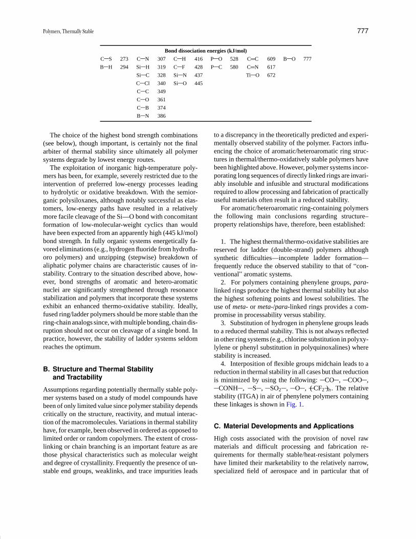
P1: GPQ Final Pages/GNB P2: GTV
Encyclopedia of Physical Science and Technology En012c-604 July 26, 2001 16:2
Polymers, Thermally Stable 777
Bond dissociation energies (kJ/mol)
C S 273 C N 307 C H 416 P O 528 C C 609 B O 777
B H 294 Si H 319 C F 428 P C 580 C N 617
Si C 328 Si N 437 Ti O 672
C Cl 340 Si O 445
C C 349
C O 361
C B 374
B N 386
The choice of the highest bond strength combinations(see below), though important, is certainly not the finalarbiter of thermal stability since ultimately all polymersystems degrade by lowest energy routes.
The exploitation of inorganic high-temperature poly-mers has been, for example, severely restricted due to theintervention of preferred low-energy processes leadingto hydrolytic or oxidative breakdown. With the semior-ganic polysiloxanes, although notably successful as elas-tomers, low-energy paths have resulted in a relativelymore facile cleavage of the Si—O bond with concomitantformation of low-molecular-weight cyclics than wouldhave been expected from an apparently high (445 kJ/mol)bond strength. In fully organic systems energetically fa-vored eliminations (e.g., hydrogen fluoride from hydroflu-oro polymers) and unzipping (stepwise) breakdown ofaliphatic polymer chains are characteristic causes of in-stability. Contrary to the situation described above, how-ever, bond strengths of aromatic and hetero-aromaticnuclei are significantly strengthened through resonancestabilization and polymers that incorporate these systemsexhibit an enhanced thermo-oxidative stability. Ideally,fused ring/ladder polymers should be more stable than thering-chain analogs since, with multiple bonding, chain dis-ruption should not occur on cleavage of a single bond. Inpractice, however, the stability of ladder systems seldomreaches the optimum.
B. Structure and Thermal Stabilityand Tractability
Assumptions regarding potentially thermally stable poly-mer systems based on a study of model compounds havebeen of only limited value since polymer stability dependscritically on the structure, reactivity, and mutual interac-tion of the macromolecules. Variations in thermal stabilityhave, for example, been observed in ordered as opposed tolimited order or random copolymers. The extent of cross-linking or chain branching is an important feature as arethose physical characteristics such as molecular weightand degree of crystallinity. Frequently the presence of un-stable end groups, weaklinks, and trace impurities leads
to a discrepancy in the theoretically predicted and experi-mentally observed stability of the polymer. Factors influ-encing the choice of aromatic/heteroaromatic ring struc-tures in thermal/thermo-oxidatively stable polymers havebeen highlighted above. However, polymer systems incor-porating long sequences of directly linked rings are invari-ably insoluble and infusible and structural modificationsrequired to allow processing and fabrication of practicallyuseful materials often result in a reduced stability.
For aromatic/heteroaromatic ring-containing polymersthe following main conclusions regarding structure–property relationships have, therefore, been established:
1. The highest thermal/thermo-oxidative stabilities arereserved for ladder (double-strand) polymers althoughsynthetic difficulties—incomplete ladder formation—frequently reduce the observed stability to that of “con-ventional” aromatic systems.
2. For polymers containing phenylene groups, para-linked rings produce the highest thermal stability but alsothe highest softening points and lowest solubilities. Theuse of meta- or meta-/para-linked rings provides a com-promise in processability versus stability.
3. Substitution of hydrogen in phenylene groups leadsto a reduced thermal stability. This is not always reflectedin other ring systems (e.g., chlorine substitution in polyxy-lylene or phenyl substitution in polyquinoxalines) wherestability is increased.
4. Interposition of flexible groups midchain leads to areduction in thermal stability in all cases but that reductionis minimized by using the following: CO , COO ,
CONH , S , SO2 , O , ( CF2 )n . The relativestability (ITGA) in air of phenylene polymers containingthese linkages is shown in Fig. 1.
C. Material Developments and Applications
High costs associated with the provision of novel rawmaterials and difficult processing and fabrication re-quirements for thermally stable/heat-resistant polymershave limited their marketability to the relatively narrow,specialized field of aerospace and in particular that of
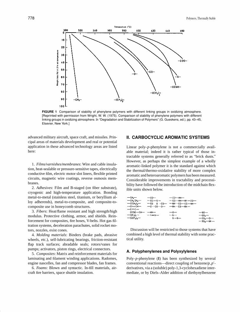
P1: GPQ Final Pages/GNB P2: GTV
Encyclopedia of Physical Science and Technology En012c-604 July 26, 2001 16:2
778 Polymers, Thermally Stable
FIGURE 1 Comparison of stability of phenylene polymers with different linking groups in oxidizing atmosphere.[Reprinted with permission from Wright, W. W. (1975). Comparison of stability of phenylene polymers with differentlinking groups in oxidizing atmosphere. In “Degradation and Stabilization of Polymers” (G. Gueskens, ed.), pp. 43–45,Elsevier, New York.]
advanced military aircraft, space craft, and missiles. Prin-cipal areas of materials development and real or potentialapplication in these advanced technology areas are listedhere:
1. Films/varnishes/membranes: Wire and cable insula-tion, heat-sealable or pressure-sensitive tapes, electricallyconductive film, electric motor slot liners, flexible printedcircuits, magnetic wire coatings, reverse osmosis mem-branes.
2. Adhesives: Film and B-staged (on fiber substrate),cryogenic and high-temperature application. Bondingmetal-to-metal (stainless steel, titanium, or beryllium al-loy adherends), metal-to-composite, and composite-to-composite use in honeycomb structures.
3. Fibers: Heat/flame resistant and high strength/highmodulus. Protective clothing, armor, and shields. Rein-forcement for composites, fire hoses, V-belts. Hot gas fil-tration systems, deceleration parachutes, solid rocket mo-tors, nozzles, exist cones.
4. Molding materials: Binders (brake pads, abrasivewheels, etc.), self-lubricating bearings, friction-resistantflap track surfaces; abradable seals; rotors/vanes forpumps; activators, piston rings, electrical connectors.
5. Composites: Matrix and reinforcement materials forlaminating and filament winding applications. Radomes,engine nascelles, fan and compressor blades, fan frames.
6. Foams: Blown and syntactic. In-fill materials, air-craft fire barriers, space shuttle insulation.
II. CARBOCYCLIC AROMATIC SYSTEMS
Linear poly-p-phenylene is not a commercially avail-able material; indeed it is rather typical of those in-tractable systems generally referred to as “brick dusts.”However, as perhaps the simplest example of a whollyaromatic-linked polymer it is the standard against whichthe thermal/thermo-oxidative stability of more complexaromatic and heteroaromatic polymers has been measured.Considerable improvements in tractability and processi-bility have followed the introduction of the midchain flex-ible units shown below.
Discussion will be restricted to those systems that havecombined a high level of thermal stability with some prac-tical utility.
A. Polyphenylenes and Polyxylylenes
Poly-p-phenylene (I) has been synthesized by severalconventional reactions—direct coupling of benzene/p,p′-derivatives, via a (soluble) poly-1,3-cyclohexadiene inter-mediate, or by Diels–Alder addition of diethynylbenzene

P1: GPQ Final Pages/GNB P2: GTV
Encyclopedia of Physical Science and Technology En012c-604 July 26, 2001 16:2
Polymers, Thermally Stable 779
and an unsubstituted bispyrene—using the relevant cat-alyst. The product from these reactions is a crys-talline intractable material that is extremely difficult toprocess. The introduction of phenyl substituents (Q)into the polymer (II) has resulted in soluble, noncrys-talline materials with relatively high molecular weight(3–6 × 10⁴).
Highly branched polyphenylenes have been producedinvolving, however, different reaction schemes than thoseused for linear systems. Polymer (III) is obtained viacure (274◦C) of a soluble, processible intermediate whileoligomer (IV) cures (cross-links) at temperatures abovemelt flow (>150◦C). Both materials have been used inhigh-temperature resin applications, the former speciallyas the matrix in carbon fiber-reinforced composites.
Poly-p-xylene (V) has been most successfully pre-pared by the controlled (steam/950◦C) pyrolysis ofp-xylene/chlorinated p-xylene via a cyclic dimer that rear-ranges (in vacuo) to yield the crystalline high-molecular-weight (∼500,000) polymer as a hard, imperviouscoating.
Poly-p-xylylene coatings (Parylenes) involving bothunsubstituted and chloro-substituted products have beensuccessfully marketed in electrical/electronic coatings ap-plications used in air and inert atmospheres at around 150and 220◦C, respectively. A comparison of properties, par-ticularly electrical, of typical Parylene, silicone, and epoxycoatings formulations is shown in Table I. The deleteriouseffect, however, of the alkylene ( CH2 CH2 ) linkingunit, particularly on thermooxidative stability, is clearlyapparent from the isothermal TGA curves (Fig. 2).
B. Polyamides
The extensive development of aromatic polyamides (ara-mids) as high-temperature polymers, particularly asthermally stable fibers, followed naturally from thecommercial successes of the wholly aliphatic systems(nylon; nylon 6,6 etc.). Aramids (VI and VII) areproduced from amino acids (A–B condensations) andfrom diacid/diamine combinations (AA–BB condensa-tions), respectively, by low-temperature interfacial orhigh-temperature solution polymerization techniques.
The use of highly polar solvents such as dimethylfor-mamide (DMF), hexa-methylphosphoramide (HMP), andN -methyl-pyrrolidone (NMP), among several others, hasbeen critical to the success of many high-temperaturepolymerization reactions used to produce both aromaticand heteroaromatic polymers.
A large number of aramids have been obtained fromwidely varied A–B and AA–BB precursors. Generally,
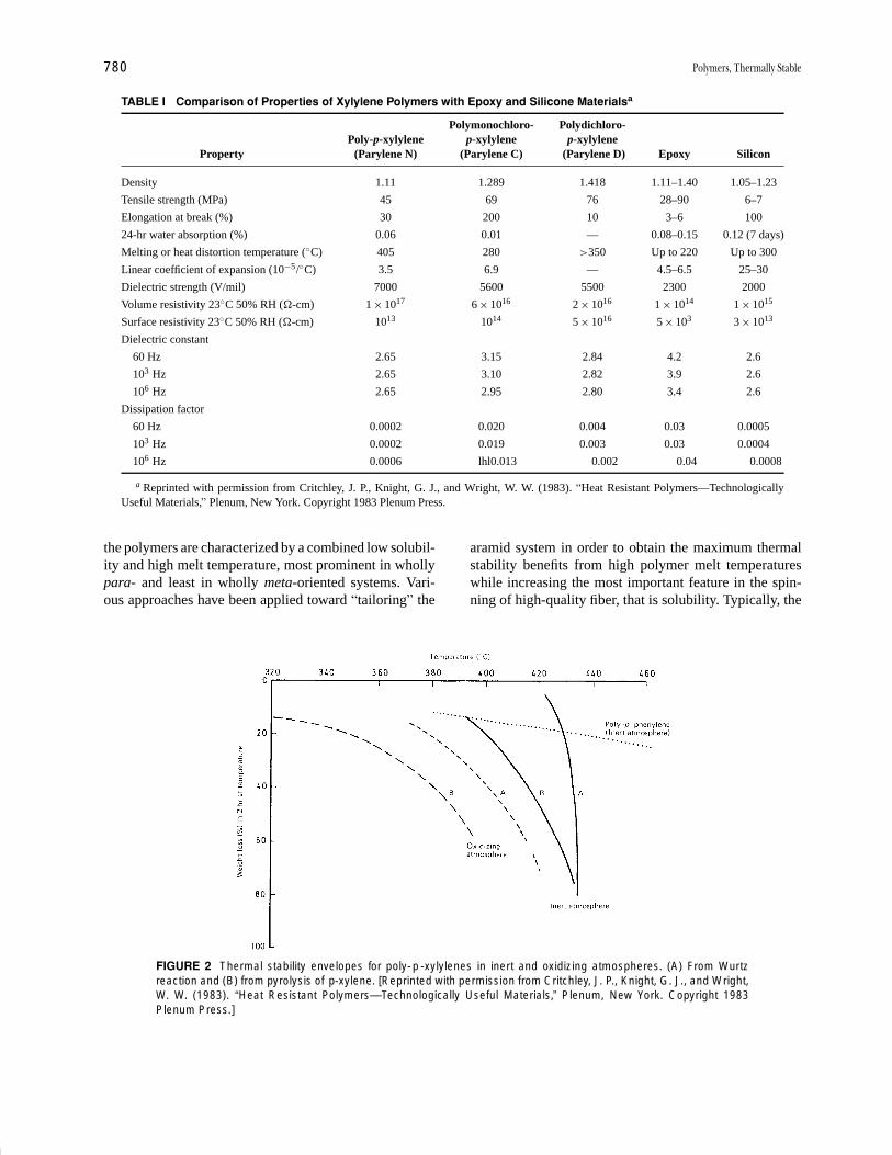
P1: GPQ Final Pages/GNB P2: GTV
Encyclopedia of Physical Science and Technology En012c-604 July 26, 2001 16:2
780 Polymers, Thermally Stable
TABLE I Comparison of Properties of Xylylene Polymers with Epoxy and Silicone Materialsa
Polymonochloro- Polydichloro-Poly-p-xylylene p-xylylene p-xylylene
Property (Parylene N) (Parylene C) (Parylene D) Epoxy Silicon
Density 1.11 1.289 1.418 1.11–1.40 1.05–1.23
Tensile strength (MPa) 45 69 76 28–90 6–7
Elongation at break (%) 30 200 10 3–6 100
24-hr water absorption (%) 0.06 0.01 — 0.08–0.15 0.12 (7 days)
Melting or heat distortion temperature (◦C) 405 280 >350 Up to 220 Up to 300
Linear coefficient of expansion (10−5/◦C) 3.5 6.9 — 4.5–6.5 25–30
Dielectric strength (V/mil) 7000 5600 5500 2300 2000
Volume resistivity 23◦C 50% RH (�-cm) 1 × 10¹⁷ 6 × 10¹⁶ 2 × 10¹⁶ 1 × 10¹⁴ 1 × 10¹⁵
Surface resistivity 23◦C 50% RH (�-cm) 1013 1014 5 × 10¹⁶ 5 × 10³ 3 × 10¹³
Dielectric constant
60 Hz 2.65 3.15 2.84 4.2 2.6
103 Hz 2.65 3.10 2.82 3.9 2.6
106 Hz 2.65 2.95 2.80 3.4 2.6
Dissipation factor
60 Hz 0.0002 0.020 0.004 0.03 0.0005
103 Hz 0.0002 0.019 0.003 0.03 0.0004
106 Hz 0.0006 lhl0.013 0.002 0.04 0.0008
a Reprinted with permission from Critchley, J. P., Knight, G. J., and Wright, W. W. (1983). “Heat Resistant Polymers—TechnologicallyUseful Materials,” Plenum, New York. Copyright 1983 Plenum Press.
the polymers are characterized by a combined low solubil-ity and high melt temperature, most prominent in whollypara- and least in wholly meta-oriented systems. Vari-ous approaches have been applied toward “tailoring” the
FIGURE 2 Thermal stability envelopes for poly-p -xylylenes in inert and oxidizing atmospheres. (A) From Wurtzreaction and (B) from pyrolysis of p-xylene. [Reprinted with permission from Critchley, J. P., Knight, G. J., and Wright,W. W. (1983). “Heat Resistant Polymers—Technologically Useful Materials,” Plenum, New York. Copyright 1983Plenum Press.]
aramid system in order to obtain the maximum thermalstability benefits from high polymer melt temperatureswhile increasing the most important feature in the spin-ning of high-quality fiber, that is solubility. Typically, the
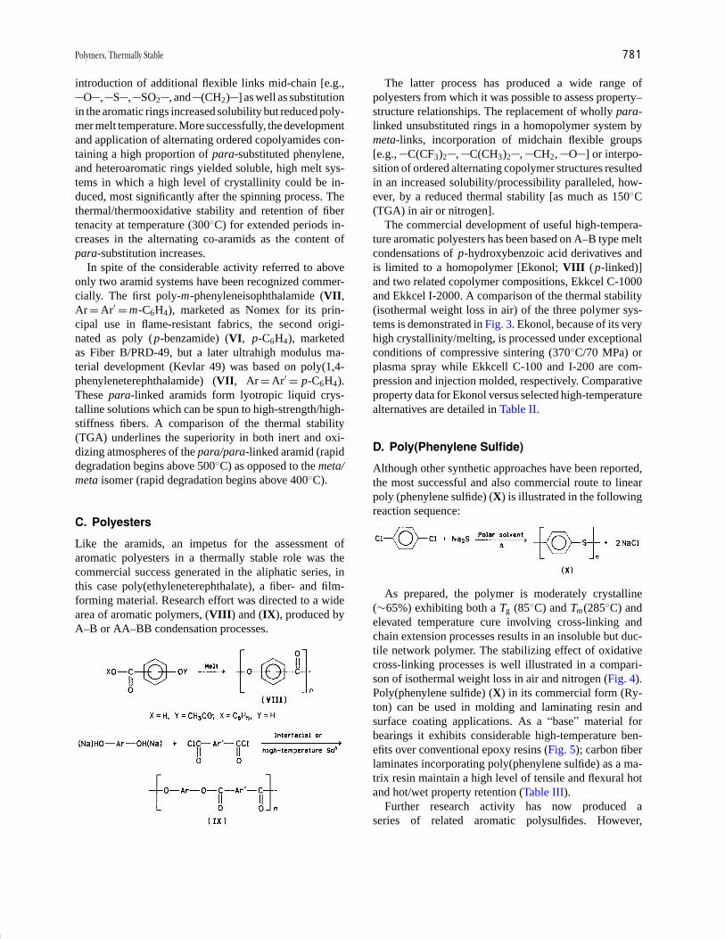
P1: GPQ Final Pages/GNB P2: GTV
Encyclopedia of Physical Science and Technology En012c-604 July 26, 2001 16:2
Polymers, Thermally Stable 781
introduction of additional flexible links mid-chain [e.g.,O , S , SO2 , and (CH2) ] as well as substitution
in the aromatic rings increased solubility but reduced poly-mer melt temperature. More successfully, the developmentand application of alternating ordered copolyamides con-taining a high proportion of para-substituted phenylene,and heteroaromatic rings yielded soluble, high melt sys-tems in which a high level of crystallinity could be in-duced, most significantly after the spinning process. Thethermal/thermooxidative stability and retention of fibertenacity at temperature (300◦C) for extended periods in-creases in the alternating co-aramids as the content ofpara-substitution increases.
In spite of the considerable activity referred to aboveonly two aramid systems have been recognized commer-cially. The first poly-m-phenyleneisophthalamide (VII,Ar = Ar′ = m-C6H4), marketed as Nomex for its prin-cipal use in flame-resistant fabrics, the second origi-nated as poly (p-benzamide) (VI, p-C6H4), marketedas Fiber B/PRD-49, but a later ultrahigh modulus ma-terial development (Kevlar 49) was based on poly(1,4-phenyleneterephthalamide) (VII, Ar = Ar′ = p-C6H4).These para-linked aramids form lyotropic liquid crys-talline solutions which can be spun to high-strength/high-stiffness fibers. A comparison of the thermal stability(TGA) underlines the superiority in both inert and oxi-dizing atmospheres of the para/para-linked aramid (rapiddegradation begins above 500◦C) as opposed to the meta/meta isomer (rapid degradation begins above 400◦C).
C. Polyesters
Like the aramids, an impetus for the assessment ofaromatic polyesters in a thermally stable role was thecommercial success generated in the aliphatic series, inthis case poly(ethyleneterephthalate), a fiber- and film-forming material. Research effort was directed to a widearea of aromatic polymers, (VIII) and (IX), produced byA–B or AA–BB condensation processes.
The latter process has produced a wide range ofpolyesters from which it was possible to assess property–structure relationships. The replacement of wholly para-linked unsubstituted rings in a homopolymer system bymeta-links, incorporation of midchain flexible groups[e.g., C(CF3)2 , C(CH3)2 , CH2, O ] or interpo-sition of ordered alternating copolymer structures resultedin an increased solubility/processibility paralleled, how-ever, by a reduced thermal stability [as much as 150◦C(TGA) in air or nitrogen].
The commercial development of useful high-tempera-ture aromatic polyesters has been based on A–B type meltcondensations of p-hydroxybenzoic acid derivatives andis limited to a homopolymer [Ekonol; VIII (p-linked)]and two related copolymer compositions, Ekkcel C-1000and Ekkcel I-2000. A comparison of the thermal stability(isothermal weight loss in air) of the three polymer sys-tems is demonstrated in Fig. 3. Ekonol, because of its veryhigh crystallinity/melting, is processed under exceptionalconditions of compressive sintering (370◦C/70 MPa) orplasma spray while Ekkcell C-100 and I-200 are com-pression and injection molded, respectively. Comparativeproperty data for Ekonol versus selected high-temperaturealternatives are detailed in Table II.
D. Poly(Phenylene Sulfide)
Although other synthetic approaches have been reported,the most successful and also commercial route to linearpoly (phenylene sulfide) (X) is illustrated in the followingreaction sequence:
As prepared, the polymer is moderately crystalline(∼65%) exhibiting both a Tg (85◦C) and Tm(285◦C) andelevated temperature cure involving cross-linking andchain extension processes results in an insoluble but duc-tile network polymer. The stabilizing effect of oxidativecross-linking processes is well illustrated in a compari-son of isothermal weight loss in air and nitrogen (Fig. 4).Poly(phenylene sulfide) (X) in its commercial form (Ry-ton) can be used in molding and laminating resin andsurface coating applications. As a “base” material forbearings it exhibits considerable high-temperature ben-efits over conventional epoxy resins (Fig. 5); carbon fiberlaminates incorporating poly(phenylene sulfide) as a ma-trix resin maintain a high level of tensile and flexural hotand hot/wet property retention (Table III).
Further research activity has now produced aseries of related aromatic polysulfides. However,
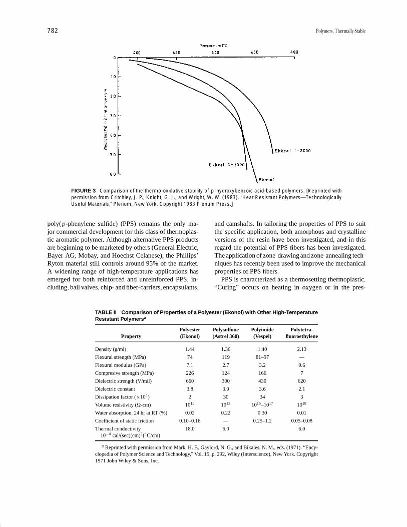
P1: GPQ Final Pages/GNB P2: GTV
Encyclopedia of Physical Science and Technology En012c-604 July 26, 2001 16:2
782 Polymers, Thermally Stable
FIGURE 3 Comparison of the thermo-oxidative stability of p -hydroxybenzoic acid-based polymers. [Reprinted withpermission from Critchley, J. P., Knight, G. J., and Wright, W. W. (1983). “Heat Resistant Polymers—TechnologicallyUseful Materials,” Plenum, New York. Copyright 1983 Plenum Press.]
poly(p-phenylene sulfide) (PPS) remains the only ma-jor commercial development for this class of thermoplas-tic aromatic polymer. Although alternative PPS productsare beginning to be marketed by others (General Electric,Bayer AG, Mobay, and Hoechst-Celanese), the Phillips’Ryton material still controls around 95% of the market.A widening range of high-temperature applications hasemerged for both reinforced and unreinforced PPS, in-cluding, ball valves, chip- and fiber-carriers, encapsulants,
TABLE II Comparison of Properties of a Polyester (Ekonol) with Other High-TemperatureResistant Polymersa
Polyester Polysulfone Polyimide Polytetra-Property (Ekonol) (Astrel 360) (Vespel) fluoroethylene
Density (g/ml) 1.44 1.36 1.40 2.13
Flexural strength (MPa) 74 119 81–97 —
Flexural modulus (GPa) 7.1 2.7 3.2 0.6
Compresive strength (MPa) 226 124 166 7
Dielectric strength (V/mil) 660 300 430 620
Dielectric constant 3.8 3.9 3.6 2.1
Dissipation factor (×104) 2 30 34 3
Volume resistivity (�-cm) 1015 1013 1016–1017 1018
Water absorption, 24 hr at RT (%) 0.02 0.22 0.30 0.01
Coefficient of static friction 0.10–0.16 — 0.25–1.2 0.05–0.08
Thermal conductivity 18.0 6.0 6.010−4 cal/(sec)(cm)2(◦C/cm)
a Reprinted with permission from Mark, H. F., Gaylord, N. G., and Bikales, N. M., eds. (1971). “Ency-clopedia of Polymer Science and Technology,” Vol. 15, p. 292, Wiley (Interscience), New York. Copyright1971 John Wiley & Sons, Inc.
and camshafts. In tailoring the properties of PPS to suitthe specific application, both amorphous and crystallineversions of the resin have been investigated, and in thisregard the potential of PPS fibers has been investigated.The application of zone-drawing and zone-annealing tech-niques has recently been used to improve the mechanicalproperties of PPS fibers.
PPS is characterized as a thermosetting thermoplastic.“Curing” occurs on heating in oxygen or in the pres-
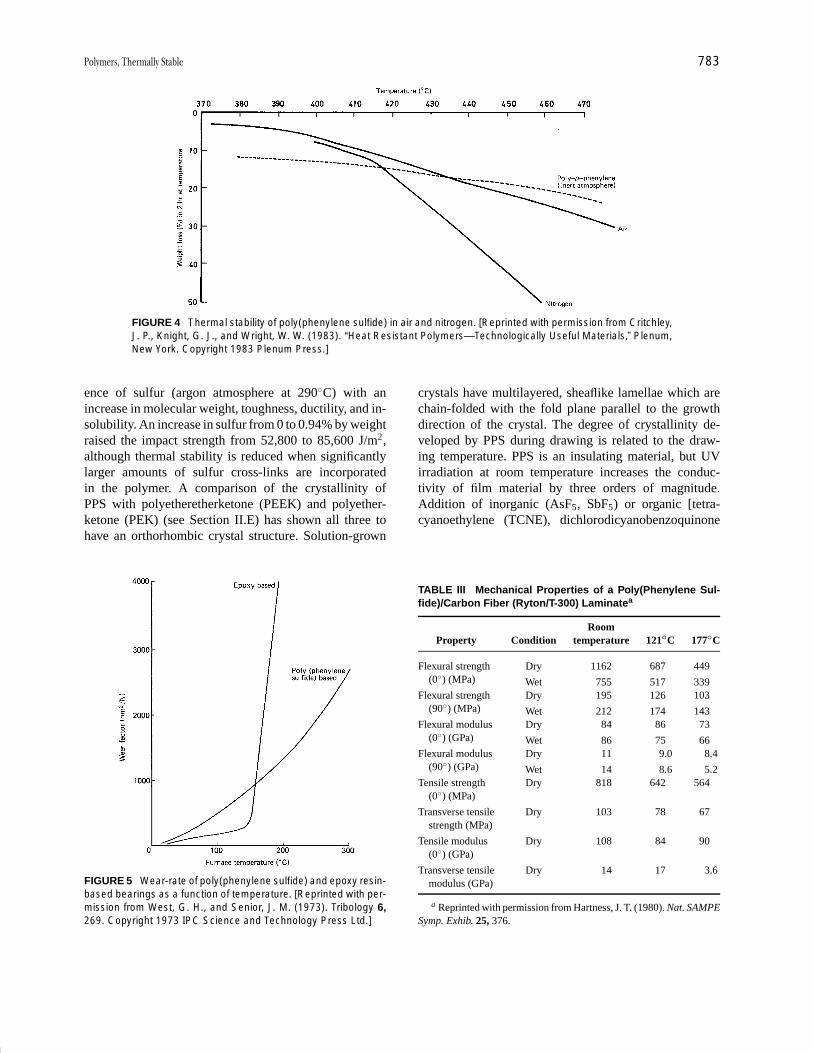
P1: GPQ Final Pages/GNB P2: GTV
Encyclopedia of Physical Science and Technology En012c-604 July 26, 2001 16:2
Polymers, Thermally Stable 783
FIGURE 4 Thermal stability of poly(phenylene sulfide) in air and nitrogen. [Reprinted with permission from Critchley,J. P., Knight, G. J., and Wright, W. W. (1983). “Heat Resistant Polymers—Technologically Useful Materials,” Plenum,New York. Copyright 1983 Plenum Press.]
ence of sulfur (argon atmosphere at 290◦C) with anincrease in molecular weight, toughness, ductility, and in-solubility. An increase in sulfur from 0 to 0.94% by weightraised the impact strength from 52,800 to 85,600 J/m2,although thermal stability is reduced when significantlylarger amounts of sulfur cross-links are incorporatedin the polymer. A comparison of the crystallinity ofPPS with polyetheretherketone (PEEK) and polyether-ketone (PEK) (see Section II.E) has shown all three tohave an orthorhombic crystal structure. Solution-grown
FIGURE 5 Wear-rate of poly(phenylene sulfide) and epoxy resin-based bearings as a function of temperature. [Reprinted with per-mission from West, G. H., and Senior, J. M. (1973). Tribology 6,269. Copyright 1973 IPC Science and Technology Press Ltd.]
crystals have multilayered, sheaflike lamellae which arechain-folded with the fold plane parallel to the growthdirection of the crystal. The degree of crystallinity de-veloped by PPS during drawing is related to the draw-ing temperature. PPS is an insulating material, but UVirradiation at room temperature increases the conduc-tivity of film material by three orders of magnitude.Addition of inorganic (AsF5, SbF5) or organic [tetra-cyanoethylene (TCNE), dichlorodicyanobenzoquinone(DDQ)] additives renders PPS electrically conductive. An
TABLE III Mechanical Properties of a Poly(Phenylene Sul-fide)/Carbon Fiber (Ryton/T-300) Laminatea
RoomProperty Condition temperature 121◦C 177◦C
Flexural strength Dry 1162 687 449
Wet 755 517 339(0◦) (MPa)
Flexural strength Dry 195 126 103
Wet 212 174 143(90◦) (MPa)
Flexural modulus Dry 84 86 73
Wet 86 75 66(0◦) (GPa)
Flexural modulus Dry 11 9.0 8.4
Wet 14 8.6 5.2(90◦) (GPa)
Tensile strength Dry 818 642 564(0◦) (MPa)
Transverse tensile Dry 103 78 67strength (MPa)
Tensile modulus Dry 108 84 90(0◦) (GPa)
Transverse tensile Dry 14 17 3.6modulus (GPa)
a Reprinted with permission from Hartness, J. T. (1980). Nat. SAMPESymp. Exhib. 25, 376.
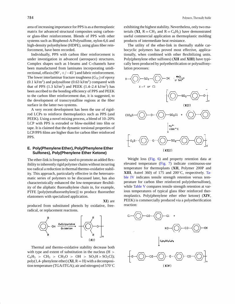
P1: GPQ Final Pages/GNB P2: GTV
Encyclopedia of Physical Science and Technology En012c-604 July 26, 2001 16:2
784 Polymers, Thermally Stable
area of increasing importance for PPS is as a thermoplasticmatrix for advanced structural composites using carbon-or glass-fiber reinforcement. Blends of PPS with othersystems such as Bisphenol-A/Polysulfone, nylon-6,6 andhigh-density polyethylene (HDPE), using glass fiber rein-forcement, have been recorded.
Individually, PPS with carbon fiber reinforcement isunder investigation in advanced (aerospace) structures.Complex shapes such as I-beams and C-channels havebeen manufactured from laminates incorporating unidi-rectional, offaxis (90◦, +/−45◦) and fabric reinforcement.The lower interlaminar fracture toughness (GIC) of epoxy(0.1 kJ/m2) and polysulfone (0.63 kJ/m2) compared withthat of PPS (1.3 kJ/m2) and PEEK (1.4–2.4 kJ/m2) hasbeen ascribed to the bonding efficiency of PPS and PEEKto the carbon fiber reinforcement due, it is suggested, tothe development of transcrystalline regions at the fibersurface in the latter two systems.
A very recent development has been the use of rigid-rod LCPs to reinforce thermoplastics such as PPS (andPEEK). Using a novel mixing process, a blend of 10–20%LCP with PPS is extruded or blow-molded into film ortape. It is claimed that the dynamic torsional properties ofLCP/PPS films are higher than for carbon fiber reinforcedPPS.
E. Poly(Phenylene Ether), Poly(Phenylene EtherSulfones), Poly(Phenylene Ether Ketone)
The ether-link is frequently used to promote an added flex-ibility to inherently rigid polymer chains without incurringtoo radical a reduction in thermal/thermo-oxidative stabil-ity. This approach, particularly effective in the heteroaro-matic series of polymers to be discussed later, has alsocharacteristically enhanced the low-temperature flexibil-ity of the aliphatic fluoroalkylene chain in, for example,PTFE [poly(tetrafluoroethylene)] to produce fluoroetherelastomers with specialized application.
Carbocyclic poly[phenylene ethers (oxides)] (XI) areproduced from substituted phenols by oxidative, free-radical, or replacement reactions.
Thermal and thermo-oxidative stability decrease bothwith type and extent of substitution in the nucleus (H >
C6H5 > CH3 > CH3O > OH > SO3H > SO2Cl);poly(1,4- phenylene ether) (XI, R = H) with a decomposi-tion temperature (TGA/ITGA); air and nitrogen) of 570◦C
exhibiting the highest stability. Nevertheless, only two ma-terials (XI, R = CH3 and R = C6H5) have demonstrateduseful commercial application as thermoplastic moldingproducts of intermediate heat resistance.
The utility of the ether-link in thermally stable car-bocyclic polymers has proved most effective, applica-tionally, when combined with other flexibilizing units.Poly(phenylene ether sulfones) (XII and XIII) have typi-cally been produced by polyetherification or polysulfony-lation processes:
Weight loss (Fig. 6) and property retention data atelevated temperature (Fig. 7) indicate continuous-usetemperature for thermoplasts (XII, Polymer 200P andXIII, Astrel 360) of 175 and 200◦C, respectively. Ta-ble IV indicates tensile strength retention versus tem-perature for carbon fiber reinforced poly(ethersulfone),while Table V compares tensile strength retention at var-ious temperatures of typical glass fiber reinforced ther-moplastics. Poly(phenylene ether ether ketone) (XIV,PEEK) is commercially produced via a polyetherificationreaction:
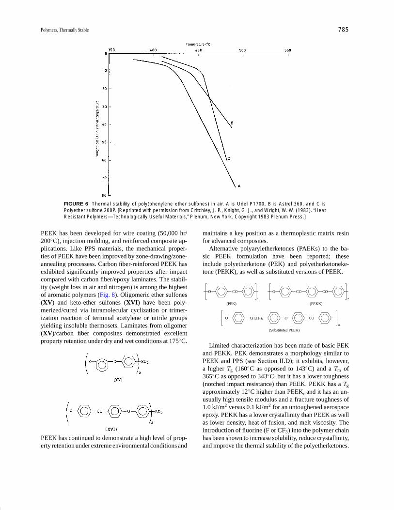
P1: GPQ Final Pages/GNB P2: GTV
Encyclopedia of Physical Science and Technology En012c-604 July 26, 2001 16:2
Polymers, Thermally Stable 785
FIGURE 6 Thermal stability of poly(phenylene ether sulfones) in air. A is Udel P1700, B is Astrel 360, and C isPolyether sulfone 200P. [Reprinted with permission from Critchley, J. P., Knight, G. J., and Wright, W. W. (1983). “HeatResistant Polymers—Technologically Useful Materials,” Plenum, New York. Copyright 1983 Plenum Press.]
PEEK has been developed for wire coating (50,000 hr/200◦C), injection molding, and reinforced composite ap-plications. Like PPS materials, the mechanical proper-ties of PEEK have been improved by zone-drawing/zone-annealing processess. Carbon fiber-reinforced PEEK hasexhibited significantly improved properties after impactcompared with carbon fiber/epoxy laminates. The stabil-ity (weight loss in air and nitrogen) is among the highestof aromatic polymers (Fig. 8). Oligomeric ether sulfones(XV) and keto-ether sulfones (XVI) have been poly-merized/cured via intramolecular cyclization or trimer-ization reaction of terminal acetylene or nitrile groupsyielding insoluble thermosets. Laminates from oligomer(XV)/carbon fiber composites demonstrated excellentproperty retention under dry and wet conditions at 175◦C.
PEEK has continued to demonstrate a high level of prop-erty retention under extreme environmental conditions and
maintains a key position as a thermoplastic matrix resinfor advanced composites.
Alternative polyaryletherketones (PAEKs) to the ba-sic PEEK formulation have been reported; theseinclude polyetherketone (PEK) and polyetherketoneke-tone (PEKK), as well as substituted versions of PEEK.
COO COO CO
n
(PEK) (PEKK)
C(CH3)2O O
(Substituted PEEK)
CO
n
n
Limited characterization has been made of basic PEKand PEKK. PEK demonstrates a morphology similar toPEEK and PPS (see Section II.D); it exhibits, however,a higher Tg (160◦C as opposed to 143◦C) and a Tm of365◦C as opposed to 343◦C, but it has a lower toughness(notched impact resistance) than PEEK. PEKK has a Tg
approximately 12◦C higher than PEEK, and it has an un-usually high tensile modulus and a fracture toughness of1.0 kJ/m2 versus 0.1 kJ/m2 for an untoughened aerospaceepoxy. PEKK has a lower crystallinity than PEEK as wellas lower density, heat of fusion, and melt viscosity. Theintroduction of fluorine (F or CF3) into the polymer chainhas been shown to increase solubility, reduce crystallinity,and improve the thermal stability of the polyetherketones.

P1: GPQ Final Pages/GNB P2: GTV
Encyclopedia of Physical Science and Technology En012c-604 July 26, 2001 16:2
786 Polymers, Thermally Stable
FIGURE 7 Tensile strength of polyethersulfones as a function of temperature. A is Udel P1700, B is Astrel 360, andC is Polyethersulfone 200P. [Reprinted with permission from Critchley, J. P., Knight, G. J., and Wright, W. W. (1983).“Heat Resistant Polymers—Technologically Useful Materials,” Plenum, New York. Copyright 1983 Plenum Press.]
For PEEK itself, a large proportion of reporting has con-centrated on polymer morphology relating, for example,the time and temperature of heating with the crystallinityof the microstructure. A study of PEEK/carbon fiber com-posites revealed that PEEK in combination with carbonfiber has a higher nucleation density than neat PEEK resin.Strong bonding at the resin–fiber interface is suggested tobe caused by crystallization on the fiber surface. Morphol-ogy and consequential physical properties of the resin aregreatly influenced by the processing conditions applied
TABLE IV Retention of Room Temperature MechanicalProperties of an Aromatic Poly(Ethersulfone) Carbon FiberComposite (200P/AS) at Elevated Temperaturea
Retention of initialTemperature room temperature
Property (◦C) value (%)
Tensile strength 175 90
Tensile modulus 175 100
Compressive strength 175 73
Compressive modulus 175 100
Flexural strength 160 58
Flexural strength 145 73
Flexural modulus 160 100
Interlaminar shear strength 160 51
Interlaminar shear strength 145 61
a Data from Hoggatt, J. T. (1975). Nat. SAMPE Symp. Exhib. 20, 606.
during the fabrication of PEEK composites. To minimizedeleterious thermal effects, it has been shown that PEEKcomposites are best fabricated under nonoxidative condi-tions at temperatures less than 400◦C. Reheating the com-posite (e.g., in repair or readjustment of lay-up) results insignificant morphological changes unless these processingconditions are retained.
Binary blends of PEEK and sulfonated PEEK (SPEEK)are miscible over the entire composition range with Torlon4000 T (amide-imide) and Ultem 1000 (ether-imide). Ithas been suggested that electron donor-accepter com-plexes involving the phenylene rings of PEEK/SPEEKand N -phenylene units of the polyimides are responsiblefor this miscibility. A single, sharp Tg for each composi-tion has been observed. The increase of Tg over that ofPEEK for some of these compositions has suggested thatblending may be a technique for improving the mechanicalproperties and increasing the heat distortion point for thesethermoplastic materials. A further method for improv-ing the thermal and mechanical properties of the PEEKshas involved polymer chain interaction/cross-linking viapendant or terminal maleimide, styryl, ethynyl, or nitrilegroups.
Unreinforced PEEK is used in a number of applications,including high-temperature bearings and seals, wire andcable coatings, and in electronics. But the main growtharea has been in advanced structural composites basedon a carbon fiber reinforced PEEK(APC-2) developedby Imperial Chemical Industries (ICI) as one of their
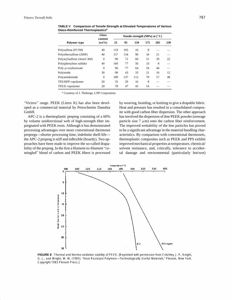
P1: GPQ Final Pages/GNB P2: GTV
Encyclopedia of Physical Science and Technology En012c-604 July 26, 2001 16:2
Polymers, Thermally Stable 787
TABLE V Comparison of Tensile Strength at Elevated Temperatures of VariousGlass-Reinforced Thermoplasticsa
Tensile strength (MPa) at (◦C)Glasscontent
Polymer type (wt%) 23 95 150 175 205 230
Polysulfone (P1700) 40 119 103 16 8 — —
Polyethersulfone (200P) 40 157 134 90 34 21 —
Polyarylsulfone (Astrel 360) 0 90 72 60 51 39 22
Poly(phenylene sulfide) 40 160 77 56 33 8 —
Poly-p-oxybenzoate 0 96 77 64 54 44 —
Polyimide 30 90 43 33 21 16 12
Polyamideimide 0 189 137 112 79 57 48
TFE/HFP copolymer 20 35 29 16 8 — —
TFE/E copolymer 20 78 47 43 14 — —
a Courtesy of J. Theberge, LNP Corporation.
“Victrex” range. PEEK (Litrex K) has also been devel-oped as a commercial material by Petrochemie DanubiaGmbH.
APC-2 is a thermoplastic prepreg consisting of a 60%by volume unidirectional web of high-strength fiber im-pregnated with PEEK resin. Although it has demonstratedprocessing advantages over more conventional thermosetprepregs—shorter processing time, indefinite shelf-life—the APC-2 prepreg is stiff and inflexible (boardy). Two ap-proaches have been made to improve the so-called drapa-bility of the prepreg. In the first a filament-to-filament “co-mingled” blend of carbon and PEEK fibers is processed
FIGURE 8 Thermal and thermo-oxidative stability of PEEK. [Reprinted with permission from Critchley, J. P., Knight,G. J., and Wright, W. W. (1983). “Heat Resistant Polymers—Technologically Useful Materials,” Plenum, New York.Copyright 1983 Plenum Press.]
by weaving, braiding, or knitting to give a drapable fabric.Heat and pressure has resulted in a consolidated compos-ite with good carbon fiber dispersion. The other approachhas involved the dispersion of fine PEEK powder (averageparticle size 7 µm) onto the carbon fiber reinforcement.The improved wettability of the fine particles has provedto be a significant advantage in the material handling char-acteristics. By comparison with conventional thermosets,thermoplastic composites such as PEEK and PPS exhibitimproved mechanical properties at temperature, chemical/solvent resistance, and, critically, tolerance to acciden-tal damage and environmental (particularly hot/wet)

P1: GPQ Final Pages/GNB P2: GTV
Encyclopedia of Physical Science and Technology En012c-604 July 26, 2001 16:2
788 Polymers, Thermally Stable
resistance. PEEK in particular offers toughness under highlevels of impact loading. A recent comparative study ofPEEK(APC-2) and PPS studied the effect of drop-weightimpact and compression after impact. Although PPS ex-hibited a high resistance to perforation, PEEK showed anability to confine the damage and hence had a markedlyimproved damage tolerance.
Most current applications for PEEK composites are inaerospace. In both fixed- and rotary-wing aircraft, rela-tively small components such as access doors and leadingedge structures are in service. A number of larger, morecomplex demonstrator structures involving main fuselageand tailplane are under development.
F. Liquid Crystal Polymers (LCPs)
Initial (pre-1985) commercial developments of LCPs in-cluded Aramid fiber (Kevlar), based on poly(1,4-phenyl-eneterephthalamide), which is a lyotropic (solvent-processed) material, and the thermotropic EkkcellI-200 (Xydar) based on p-hydroxybenzoic acid. Since1985 thermotropic LCPs have been developed by duPontand Hoechst-Celanese based on aromatic and condensedaromatic (naphthalene-based) copolyesters which com-bine a high level of processability with durability andstiffness. Both amorphous and crystalline LCPs—theamorphous-crystalline terminology refers to secondarythermal transitions detected by TGA—have been pro-cessed by injection/blow-molding, extrusion (into filmand sheet), and thermoforming techniques. The largestoutlets for the LCPs are currently in the field of electronicand electrical components in which unreinforced andreinforced (glass- and mineral-filled) have been used.Surface-mount applications of these components requirehigh dimensional and thermal stability provided by theLCPs during vapor phase or infrared soldering.
III. HETEROCYCLIC AROMATIC(HETEROAROMATIC) SYSTEMS
Heteroaromatic systems have been influential in thedevelopment of thermally stable organic polymers. Some40 to 50 polymers have been produced in which pheny-lene rings alternate or are condensed with predominantlynitrogen containing 5- or 6-membered heterocyclic rings.Significantly, it has been possible to develop excep-tionally high levels of stability in often insoluble andintractable polymers that have themselves been obtainedfrom high-molecular-weight soluble and processableprecursor polymers via “postpolymerization cyclization”reactions. Even so in some instances, for example,with certain polyquinoxalines and polybenzimidazoles,structural “tailoring” of the final macromolecule made it
possible to achieve an acceptable solubility and proces-sibility without intervention of a prepolymer. Syntheticactivity was greatest during the 1960s and early 1970s;since then the effort has concentrated on applicationaldevelopments and, as a result, it has been necessary tocompromise between thermal/thermooxidative stabilityand processibility.
With the notable exception of the polyimides and arylcyanate ester resins, as well as to a lesser extent the ordered(rigid-rod) polybenzazoles (see below), during the pastdecade there has been a marked decrease in publishedreferences to the heteroaromatic polymer systems, someof which are mentioned below. The continued presenceof such systems in this account is, however, intended toreflect the intense activity directed into the developmentof these thermally stable polymers during the 1960s and1970s.
A. Ring-Chain
1. Poly(1,3,4-Oxadiazoles)
Several routes exist to aromatic poly(1,3,4-oxadiazoles)(XVII), however, cyclization of preformed polyhydra-zides has proved most productive of useful (fibers, films)materials.
Aromatic polyhydrazides are soluble in polar sol-vents and can be solution-cast or spun into films andfibers, which on cyclodehydration yield insoluble in-tractable poly(1,3,4-oxadiazoles) in the same materialform. The wholly aromatic system (XVII; R = m-C6H4,
R1 = p-C6H4) in the form of fiber or film exhibits a60% strength retention in air after 24 hr at 400◦C,50% after 700 hr at 300◦C. Introduction of flexiblegroups midchain leads to an increase in tractability buta decline in thermal/thermooxidative stability. Aliphatic-linked poly(1,3,4-oxadiazoles), for example, are readilysoluble in polar solvents with melt temperatures around150–200◦C (aromatics > 400◦C) and major (TGA) weightloss in both inert and oxidizing atmospheres between 300and 350◦C (aromatics 400–480◦C).
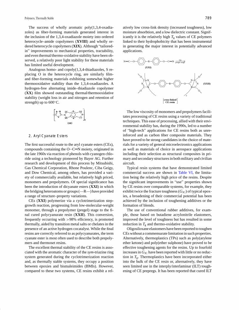
P1: GPQ Final Pages/GNB P2: GTV
Encyclopedia of Physical Science and Technology En012c-604 July 26, 2001 16:2
Polymers, Thermally Stable 789
The success of wholly aromatic poly(1,3,4-oxadia-zoles) as fiber-forming materials generated interest inthe inclusion of the 1,3,4-oxadiazole moiety into orderedheterocycle–amide copolymers (XVIII) and wholly or-dered heterocycle copolymers (XIX). Although “tailored-in” improvements to mechanical properties, tractability,and even thermal/thermo-oxidative stability have been ob-served, a relatively poor light stability for these materialshas limited useful development.
Analogous homo- and copoly(1,3,4-thiadiazoles, S re-placing O in the heterocycle ring, are similarly film-and fiber-forming materials exhibiting somewhat higherthermooxidative stability than the 1,3,4-oxadiazoles. Ahydrogen-free alternating imide–thiadiazole copolymer(XX) film showed outstanding thermal/thermooxidativestability (weight loss in air and nitrogen and retention ofstrength) up to 600◦C.
2. Aryl Cyanate Esters
The first successful route to the aryl cyanate esters (CEs),compounds containing the O C N moiety, originated inthe late 1960s via reaction of phenols with cyanogen chlo-ride using a technology pioneered by Bayer AG. Furtherresearch and development of this process by Mitsubishi,Gas Chemical Corporation, Rhone Poulenc, Ciba Geigy,and Dow Chemical, among others, has provided a vari-ety of commercially available, but relatively high priced,monomers and prepolymers. Of special significance hasbeen the introduction of dicyanate esters (XXI) in whichthe bridging heteroatoms or groups (—R—) have provideda range of structure–property variations.
CEs (XXI) polymerize via a cyclotrimerization step-growth reaction, progressing from low-molecular-weightmonomer, through a prepolymer (pregel) stage to the fi-nal cured polycyanurate resin (XXII). This conversion,frequently occurring with >98% efficiency, is promotedthermally, aided by transition metal salts or chelates in thepresence of an active hydrogen cocatalyst. While the finalresins are correctly referred to as polycyanurates, the termcyanate ester is most often used to describe both prepoly-mers and thermoset resins.
The excellent thermal stability of the CE resins is asso-ciated with the aromatic character of the sym-triazine ringsystem generated during the cyclotrimerization reactionand, as thermally stable systems, they occupy a positionbetween epoxies and bismaleimides (BMIs). However,compared to these two systems, CE resins exhibit a rel-
atively low cross-link density (increased toughness), lowmoisture absorbtion, and a low dielectric constant. Signif-icantly it is the relatively high Tg values of CE polymerslinked to their hydrophobicity that has been instrumentalin generating the major interest in potentially advancedapplications.
OCN R O C Nvia
pregel stage
ONC
NC N
C
O
O
RCN
CN C
NO
O
O
n
(XXII)
(XXI)
cross-linkedCE resin
The low viscosity of monomers and prepolymers facili-tates processing of CE resins using a variety of traditionaltechniques. This ease of processing, allied with their envi-ronmental stability has, during the 1990s, led to a numberof “high-tech” applications for CE resins both as unre-inforced and as carbon fiber composite materials. Theyhave proved to be strong candidates in the choice of mate-rials for a variety of general microelectronics applicationsas well as materials of choice in aerospace applicationsincluding their selection as structural composites in pri-mary and secondary structures in both military and civilianaircraft.
Typical resin systems that have demonstrated limitedcommercial success are shown in Table VI, the limita-tion being the relatively high price of the resins. Despitethe significant improvements in “use” properties shownby CE resins over comparable systems, for example, theyexhibit twice the fracture toughness (GIC) of typical epox-ies, a broadening of their commercial potential has beenachieved by the inclusion of toughening additives or theformation of blends.
The use of conventional rubber additives, for exam-ple, those based on butadiene acrylonitrile elastomers,improved the level of toughness but has resulted in somereduction in Tg and thermo-oxidative stability.
Oligosiloxane elastomers have been reported to toughenCEs without a commensurate limitation in such properties.Alternatively, thermoplastics (TPs) such as poly(aryleneether ketone) and poly(ether sulphone) have proved to beeffective toughening agents for the resins. Up to fourfoldincreases in GIC have been reported with little or no reduc-tion in Tg. Thermoplastics have been incorporated eitherinto the bulk of the CE resin or, alternatively, they haveseen limited use in the interply/interlaminar (ILT) tough-ening of CE prepregs. It has been reported that cured ILT
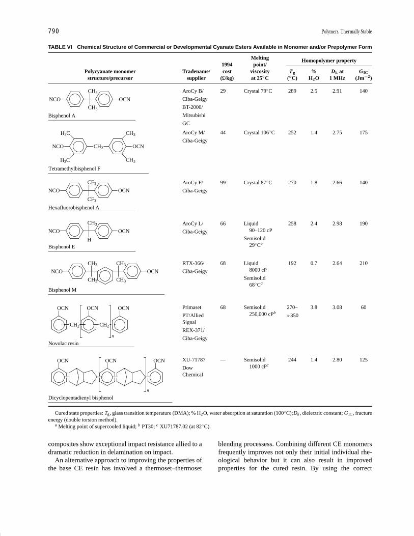
P1: GPQ Final Pages/GNB P2: GTV
Encyclopedia of Physical Science and Technology En012c-604 July 26, 2001 16:2
790 Polymers, Thermally Stable
TABLE VI Chemical Structure of Commercial or Developmental Cyanate Esters Available in Monomer and/or Prepolymer Form
Homopolymer propertyMelting1994 point/
Polycyanate monomer Tradename/ cost viscosity Tg % Dk at GIC
structure/precursor supplier (£/kg) at 25◦C (◦C) H2O 1 MHz (Jm−2)
NCO OCN
CH3
CH3
Bisphenol A
AroCy B/ 29 Crystal 79◦C 289 2.5 2.91 140
Ciba-Geigy
BT-2000/
Mitsubishi
GC
NCO
Tetramethylbisphenol F
CH2
H3C
H3C
OCN
CH3
CH3
AroCy M/ 44 Crystal 106◦C 252 1.4 2.75 175
Ciba-Geigy
NCO OCN
CF3
CF3
Hexafluorobisphenol A
AroCy F/ 99 Crystal 87◦C 270 1.8 2.66 140
Ciba-Geigy
NCO OCN
CH3
HBisphenol E
AroCy L/ 66 Liquid 258 2.4 2.98 190
Ciba-Geigy 90–120 cP
Semisolid29◦Ca
NCO
CH3
CH3
Bisphenol M
CH3
CH3
OCN
RTX-366/ 68 Liquid 192 0.7 2.64 210
Ciba-Geigy 8000 cP
Semisolid68◦Ca
OCN
CH2
OCN
CH2
OCN
n
Novolac resin
Primaset 68 Semisolid 270– 3.8 3.08 60
PT/Allied >350250,000 cPb
Signal
REX-371/
Ciba-Geigy
OCN
Dicyclopentadienyl bisphenol
OCN OCN
n
XU-71787 — Semisolid 244 1.4 2.80 125
Dow 1000 cPc
Chemical
Cured state properties: Tg, glass transition temperature (DMA); % H2O, water absorption at saturation (100◦C);Dk , dielectric constant; GIC, fractureenergy (double torsion method).
a Melting point of supercooled liquid; b PT30; c XU71787.02 (at 82◦C).
composites show exceptional impact resistance allied to adramatic reduction in delamination on impact.
An alternative approach to improving the properties ofthe base CE resin has involved a thermoset–thermoset
blending processess. Combining different CE monomersfrequently improves not only their initial individual rhe-ological behavior but it can also result in improvedproperties for the cured resin. By using the correct

P1: GPQ Final Pages/GNB P2: GTV
Encyclopedia of Physical Science and Technology En012c-604 July 26, 2001 16:2
Polymers, Thermally Stable 791
blends, significant improvements have been observed forthermal/thermo-oxidative stability and hot-wet mechani-cal strength.
Epoxy resins are miscible with, and coreact with, CEresins resulting in hybrid products with improved prop-erties, e.g., increased Tg and better electrical resistancecompared with the parent epoxy.
A number of epoxy/CE systems have been used in ap-plications where the relative cheapness of the epoxy resinmakes a significant difference to the commercial viabilityof the product. Blending CEs with BMIs has enhancedthe toughness characteristics of the latter resin systemsand a range of blended materials (SkyflexR BT resins) hasbeen produced by Mitsubishi Gas Chemical Corporation.Originally it was believed that the CE/BMI resin systemscoreacted on blending. However, it is now considered thatan interpenetrating network (IPN) is established, indicatedby the fact that two disinct Tg values are observed origi-nating from the independent CE and BMI networks. Thelower valued of these Tg values governs the “use” temper-ature of the blend.
The introduction of reactive allyl groups into the CEmonomer has been reported to facilitate copolymerizationwith the BMI component, producing a linked interpene-trating network (LPN) with a single high Tg and a GIC
higher than for either homopolymer.
B. Bi- and Tricyclic Polymers
1. Polybenzazoles—Polybenzimidazoles
The extension of conventional polycondensation pro-cesses from simple aliphatic systems to high-temperatureheteroaromatic polymers was first observed for thepolybenzimidazoles (PBIs). Practical, semicommercialapplications—adhesives, fibers, composites—were soonevaluated, but this initial progress was not sustained andthe aromatic polyimides soon took, and retained, “center-stage” as the most important applicational heteroaromaticpolymer system. However, techniques of synthesis, andstructure versus property data evaluated for PBIs havebeen of considerable value in the development of otherpolyheteroaromatics.
The main synthetic route to PBIs involves the reactionof aromatic tetraamine with dicarboxylic acid esters un-der melt conditions, typified below for the formation ofpoly(2,2′-m-phenylene-5,5′-bibenzimidazole) (XXIII)
A staged heating (220–280◦C) under nitrogen producesan oligomeric prepolymer with evolution of phenol andwater; above 350◦C (in vacuo) complete conversion tothe high-molecular-weight, intractable PBI occurs via asolid-state process. Most PBI variants have been producedby this melt–polycondensation route; however, a limitednumber are prepared in solution using high boiling polarsolvents. Examples are the formation of the substitutedPBIs (XXIV) via the “open-chain” poly(aminoamide) in-termediates:
and interaction of aromatic tetraamines with bisor-thoesters to produce high-molecular-weight film- andfiber-forming PBIs (XXV).
Structural modifications to the wholly aromatic PBIsystem have involved incorporation of both relatively sim-ple midchain flexible groups [( ( CH2 )n), SO2 , O ]and more complex units such as siloxanes
In general, improvements that these groups make to thesolubility/processibility of the polymers are linked withreductions in thermal/thermooxidative stability. However,the substitution of the imidazole N—H by N -phenyl(XXIV) provides an improvement to both processibilityand long-term thermooxidative stability (Fig. 9). A com-parison of weight loss data for typical wholly aromaticheterocyclic polymers, first under inert conditions (TGA)then in air (ITGA), highlights the basic oxidative instabil-ity of the PBI system:

P1: GPQ Final Pages/GNB P2: GTV
Encyclopedia of Physical Science and Technology En012c-604 July 26, 2001 16:2
792 Polymers, Thermally Stable
FIGURE 9 Isothermal weight loss in air for PBI and N-phenyl PBI.[Courtesy of Spain, R. G., and Ray, J. D. (1967). In “Conferenceon Stability of Plastics,” pp. E1–E4, Society of Plastic Engineering,Washington, DC.]
1. Helium (TGA)Polybenzothiazoles ≥ polybenzimidazoles
> polyimides > polybenzoxazoles> polyquinoxalines
2. Air (ITGA)Polyimides > polybenzoxazoles
> polyquinoxalines > polybenzothiazoles> poly-N -phenylbenzimidazoles� polybenzimidazoles
Materials applications such as glass-reinforced com-posites and filament-wound structures, metal-to-metal ad-hesives, films, fibers, and foams have involved only thewholly aromatic PBI (XXIII) Processing is conducted atthe prepolymer stage and, for the adhesives and laminates,a major drawback is that they must be stored under re-frigerated conditions. The only application to have madesome headway against strong competition from the poly-imides is the PBI fiber. Postspinning techniques of orienta-tion/crystallization of the predominantly amorphous fiberallow the attainment of optimum properties. PBI fibers ex-hibit outstanding nonflammability/low smoke generationin air under extreme conditions; fabrics have been chosenfor the hazardous environments associated with aircraftand spacecraft.
2. Polybenzazoles—Ordered Polymers
Highly ordered (rodlike) polymers derived from whollypara-linked polybenzazoles (XXVI) have been developedprimarily as high-temperature fibers and self-reinforcingresins.
Typically, PBO (XXVI, X = O) was originally developedas a fiber by the Stanford Research Institute. It is nowmarketed as ZylonR by Dow Chemical, Co. who, in con-junction with the Toyobo Research Center (Japan), havedevised a unique spinning technology to produce fiberwith a tenacity >5.8 GPa.
Polybenzothiazoles (PBT) and polybenzoxazoles(PBO) have merited particular attention since, like theordered aromatic polyamides, they form liquid crystallinesolutions. They are prepared in polyphosphoric acid (PPA)solution with very high intrinsic viscosities ∼30 dL/g. Thespinning of the liquid crystalline solutions provides fibersof exceptional stiffness and strength. Typical of the het-eroaromatic polymers, thermooxidative stability is high(superior to the ordered polyamides); for PBT, weightlosses of 2% at 316◦C and 50% at 371◦C after 200 hrhave been reported. A comparison of strength and modu-lus properties of PBT and conventional reinforcing fibersis shown in Table VII. In a further development both PBOand PBT are under investigation as high-strength/high-modulus resins. In this material form, the elimination of
TABLE VII Tensile Properties of OrderedPBT Fibers Compared with AlternativeReinforcementsa
Tensile Tensilestrength modulus Specific
Fiber material (MPa) (GPa) gravity
Boron 3174 414 2.60
Alumina 1380–3450 380 3.60
Silicon carbide 3450 290–331 3.20
Carbon 2346–5500 207–345 1.78
Polybenzamide 2760 131 1.45
Polyethylene 3001 90 0.95–0.98
Polybenzothiazole 1518 186 1.40
E Glass 1725 69 2.54
Polyterephalimide 3720 124 1.44(Kevlar 49)
a Reprinted with permission from Critchley, J. P.,Knight, G. J., and Wright, W. W. (1983). “Heat ResistantPolymers—Technologically Useful Materials,” Plenum,New York. Copyright 1983 Plenum Press.
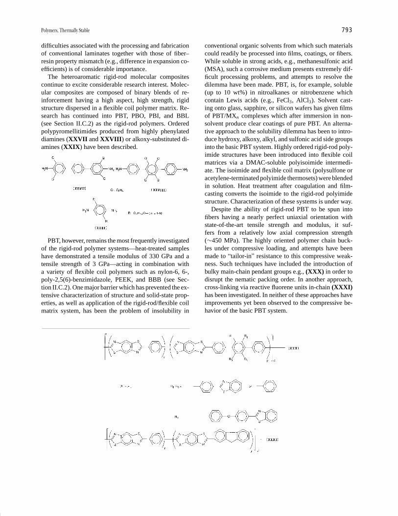
P1: GPQ Final Pages/GNB P2: GTV
Encyclopedia of Physical Science and Technology En012c-604 July 26, 2001 16:2
Polymers, Thermally Stable 793
difficulties associated with the processing and fabricationof conventional laminates together with those of fiber–resin property mismatch (e.g., difference in expansion co-efficients) is of considerable importance.
The heteroaromatic rigid-rod molecular compositescontinue to excite considerable research interest. Molec-ular composites are composed of binary blends of re-inforcement having a high aspect, high strength, rigidstructure dispersed in a flexible coil polymer matrix. Re-search has continued into PBT, PBO, PBI, and BBL(see Section II.C.2) as the rigid-rod polymers. Orderedpolypyromellitimides produced from highly phenylateddiamines (XXVII and XXVIII) or alkoxy-substituted di-amines (XXIX) have been described.
PBT, however, remains the most frequently investigatedof the rigid-rod polymer systems—heat-treated sampleshave demonstrated a tensile modulus of 330 GPa and atensile strength of 3 GPa—acting in combination witha variety of flexible coil polymers such as nylon-6, 6-,poly-2,5(6)-benzimidazole, PEEK, and BBB (see Sec-tion II.C.2). One major barrier which has prevented the ex-tensive characterization of structure and solid-state prop-erties, as well as application of the rigid-rod/flexible coilmatrix system, has been the problem of insolubility in
conventional organic solvents from which such materialscould readily be processed into films, coatings, or fibers.While soluble in strong acids, e.g., methanesulfonic acid(MSA), such a corrosive medium presents extremely dif-ficult processing problems, and attempts to resolve thedilemma have been made. PBT, is, for example, soluble(up to 10 wt%) in nitroalkanes or nitrobenzene whichcontain Lewis acids (e.g., FeCl3, AlCl3). Solvent cast-ing onto glass, sapphire, or silicon wafers has given filmsof PBT/MXn complexes which after immersion in non-solvent produce clear coatings of pure PBT. An alterna-tive approach to the solubility dilemma has been to intro-duce hydroxy, alkoxy, alkyl, and sulfonic acid side groupsinto the basic PBT system. Highly ordered rigid-rod poly-imide structures have been introduced into flexible coilmatrices via a DMAC-soluble polyisoimide intermedi-ate. The isoimide and flexible coil matrix (polysulfone oracetylene-terminated polyimide thermosets) were blendedin solution. Heat treatment after coagulation and film-casting converts the isoimide to the rigid-rod polyimidestructure. Characterization of these systems is under way.
Despite the ability of rigid-rod PBT to be spun intofibers having a nearly perfect uniaxial orientation withstate-of-the-art tensile strength and modulus, it suf-fers from a relatively low axial compression strength(∼450 MPa). The highly oriented polymer chain buck-les under compressive loading, and attempts have beenmade to “tailor-in” resistance to this compressive weak-ness. Such techniques have included the introduction ofbulky main-chain pendant groups e.g., (XXX) in order todisrupt the nematic packing order. In another approach,cross-linking via reactive fluorene units in-chain (XXXI)has been investigated. In neither of these approaches haveimprovements yet been observed to the compressive be-havior of the basic PBT system.

P1: GPQ Final Pages/GNB P2: GTV
Encyclopedia of Physical Science and Technology En012c-604 July 26, 2001 16:2
794 Polymers, Thermally Stable
Other potential cross-link sites have been introducedinto the rigid-rod (PBT/PBO) molecules. These includemethyl, halogen, ethynyl, phenylene sulfide, and cy-clobutene (BCB) moieties. The cyclobutene derivativesare reported to cross-link via quinone methide intermedi-ates, which then undergo cycloaddition or dimerizationreactions. In the case of the PBT/BCB system, phaseseparation occurred between rigid-rod and matrix com-ponents and the desired synergystic effects were not re-alized. However, with the PBO/BCB system, there wasno phase separation after heat treatment and this resultedin excellent tensile properties and improved resistance todelamination.
In a novel approach, bulk rigid-rod molecular compos-ites (XXXII) have been obtained by powder consolidationof a copolymer with a PBT derivative as the backbonereinforcement and polyetherketone (PEK) thermoplasticside chains as the flexible matrix. Compared to PEK ho-mopolymer, copolymers with a low rod content exhibitedsignificant increases in Tg and tensile properties. However,higher rod content resulted in a significant phase separa-tion and consequent decreases in Tg and reinforcementefficiency of the molecular composite.
S
NO O
N
S S
N
N
S
CO
O
x y
n
(XXXII)
3. Polyimides
The emergence of polyimides as technologically and com-mercially viable materials remains the cornerstone of ac-tivity for thermally stable heteroaromatic polymers. Thisresults both from the ability to adapt available syntheticroutes to the increasing requirement for processable prod-ucts as well as the high level of thermal/thermo-oxidativestability compared for example with other heteroaromaticsystems (Fig. 10).
Research and development into the aromatic polyimidesremains the most prolific and productive area of the het-eroaromatic polymers. Activity has covered condensationand addition-type systems, the former produced predom-inantly via postpolymerization cyclization of precursorpoly(amic-acids). Although condensation polymers werethe first to be commercially exploited (e.g., H-film), the ad-dition systems subsequently provided the major commer-
cial advances, particularly in the field of advanced com-posites. However, in the 1990s there was renewed interestin the synthesis, structure, and commercial potential of thecondensation-type polymers.
a. Condensation polyimides. Wholly aromaticpolyimides (XXXIII) are almost invariably insoluble andinfusible; as a result while strictly not cross-linked, at leastas prepared, they are referred to as “thermoset types.” Syn-thesis involves the low-temperature polycondensation (indipolar aprotic solvents) of a dianhydride and diamineto produce a soluble/fusible intermediate poly(amic acid)followed by a chemically or, preferentially, thermally in-duced postpolymerization cyclization.
A � ,CO
,
R � , O , SO2
COO
CO
COO � H2N
CO
A R NH2A
COOH
HOOC CONH
NHCO
Rn
�2H2OCO
N
CO
CO
N
CO
A R
n
(XXXIII)
e.g.,
A vast array of aromatic polyimides—particularlypolypy romellitimides
A �(XXXIII);
has been produced. The approach via the soluble inter-mediate is especially suitable for the formation of films,coatings, and fibers but to achieve optimum properties(high molecular weight) the control of precursor purityand stoichiometry/mixing order is critical as is also thestorage of the hydrolytically unstable poly(amic acid)under rigorously dry refrigerated conditions. For lam-inating/adhesive formulations the attainment of a highmolecular weight is less important than are those pro-cessing problems associated with a limited shelf-lifedintermediate, void-forming volatiles (water, high boil-ing solvent) liberated during cyclization, and the prox-imity of softening/flow temperature to that of cyclodehy-dration. These processing difficulties have been reducedusing variously modified poly(amic acids) and, for ex-ample, the diacetylated intermediate (XXXIV) preparedin low-boiling solvents is hydrolytically stable with a

P1: GPQ Final Pages/GNB P2: GTV
Encyclopedia of Physical Science and Technology En012c-604 July 26, 2001 16:2
Polymers, Thermally Stable 795
FIGURE 10 Isothermal weight loss in air (371◦C) for various heteroaromatic polymers. [Reprinted with permissionfrom Hergenrother, P. M. (1971). High temperature organic adhesives, SAMPE Q. 3, 1. Copyright 1971 SAMPE.]
temperature of cyclization significantly above that of resinflow.
COO
CO
COO � CH3CONH
CO
A R NHCOCH3acetone
� 50°CA
COOH
CON
NCO
R
n
COCH3
COCH3
(XXXIV)
HOOC
�2CH3CO2H
>250°C
CO
N
CO
CO
N
CO
A R
(XXXIII)
Commercial exploitation of thermoset polyimidesbased principally on pyromellitic dianhydride (PMDA)or benzofenone dianhydride (BTDA) includes Kapton Hand HF (films), Pyre-ML (coating), Vespel (SP moldinggrades), Pyralin (glass prepreg), Skybond (solutions forfilms, coatings, varnishes), FM-34 (adhesive) and QX-13(glass/carbon-reinforced prepreg).
“Thermoplastic” aromatic polyimides are designed toovercome the processing problems of the thermoset sys-tems. Modifications to the basic polymer structure haveconferred sufficient solubility and/or fusibility to allow,in some cases, fabrication by conventional thermoplas-tic techniques at the fully imidized stage. Bulky groupspresent in polymers. (XXXV) and (XXXVI), reducecrystallinity and close packing effects enhancing solu-bility (in polar solvents), but not fusibility (Tg values>400◦C), without affecting the characteristically excel-lent aromatic–imide thermal/thermooxidative stability.
Tractability and hence processability are significantlyincreased by introducing extended flexible “hinge” groupsinto the chain, but in polymers
CO
N
CO
CON
CO
A
(XXXV)
C
CO
X
n
C6H5
C6H5
R
CO
N
CO
C6H5
C6H5
C6H5
C6H5
CO
N
CO
R
n
(XXXVI)
(XXXIII); R � (CH2)y or Si
CH3
CH3
O Si
CH3
CH3
(CH2)y
for example, the aliphatic content induces a much lower(∼100◦C drop) thermo-oxidative stability. Alternativeshave been investigated; in polymers (XXXVII) and(XXXVIII) adequate processibility does not, however,preclude a high thermal or thermo-oxidative stability.
NCO
CO C(CF2)3
(XXXVII)
N
CO
CO
n
N
CO
CO C(CF3)2
(XXXVIII)
N
CO
COn
O
The application of these thermoplastic fluoro-polyimides as structural adhesives or laminating resins
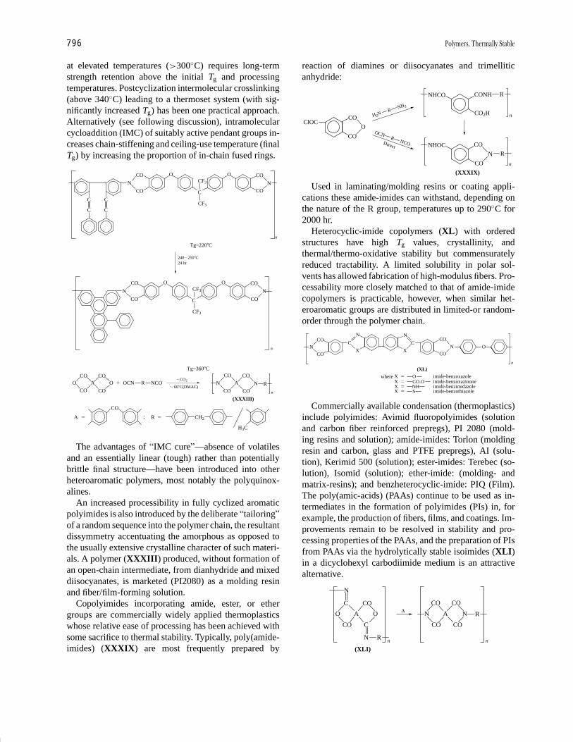
P1: GPQ Final Pages/GNB P2: GTV
Encyclopedia of Physical Science and Technology En012c-604 July 26, 2001 16:2
796 Polymers, Thermally Stable
at elevated temperatures (>300◦C) requires long-termstrength retention above the initial Tg and processingtemperatures. Postcyclization intermolecular crosslinking(above 340◦C) leading to a thermoset system (with sig-nificantly increased Tg) has been one practical approach.Alternatively (see following discussion), intramolecularcycloaddition (IMC) of suitably active pendant groups in-creases chain-stiffening and ceiling-use temperature (finalTg) by increasing the proportion of in-chain fused rings.
N
CO
CO O
n
C
CF3
CF3 N
O CO
CO
C C
C C
Tg~220�C
240�250�C24 hr
N
CO
CO O
n
C
CF3
CF3
O
N
CO
CO
Tg~360�C
OCO
A
CO
COO
CO
� OCN R NCOCO2�
� 60�C(N
COA
CO
CO
NCO
R
n
(XXXIII)
A �
CO
; R � CH2
H3C
DMAC)
The advantages of “IMC cure”—absence of volatilesand an essentially linear (tough) rather than potentiallybrittle final structure—have been introduced into otherheteroaromatic polymers, most notably the polyquinox-alines.
An increased processibility in fully cyclized aromaticpolyimides is also introduced by the deliberate “tailoring”of a random sequence into the polymer chain, the resultantdissymmetry accentuating the amorphous as opposed tothe usually extensive crystalline character of such materi-als. A polymer (XXXIII) produced, without formation ofan open-chain intermediate, from dianhydride and mixeddiisocyanates, is marketed (PI2080) as a molding resinand fiber/film-forming solution.
Copolyimides incorporating amide, ester, or ethergroups are commercially widely applied thermoplasticswhose relative ease of processing has been achieved withsome sacrifice to thermal stability. Typically, poly(amide-imides) (XXXIX) are most frequently prepared by
reaction of diamines or diisocyanates and trimelliticanhydride:
CO
O
CO
NHCO CONH R
CO2H
NHOC CO
R
CO
(XXXIX)
H2NR
NH2
OCNR
NCO
N
n
n
ClOC
Direct
Used in laminating/molding resins or coating appli-cations these amide-imides can withstand, depending onthe nature of the R group, temperatures up to 290◦C for2000 hr.
Heterocyclic-imide copolymers (XL) with orderedstructures have high Tg values, crystallinity, andthermal/thermo-oxidative stability but commensuratelyreduced tractability. A limited solubility in polar sol-vents has allowed fabrication of high-modulus fibers. Pro-cessability more closely matched to that of amide-imidecopolymers is practicable, however, when similar het-eroaromatic groups are distributed in limited-or random-order through the polymer chain.
CO
NCO
CO
N
CO
N
C
X
N
C
XO
where X � O imide-benzoxazoleX � CO.O imide-benzoxazinoneX � NH imide-benzimidazoleX � S imide-benzothiazole
n
(XL)
Commercially available condensation (thermoplastics)include polyimides: Avimid fluoropolyimides (solutionand carbon fiber reinforced prepregs), PI 2080 (mold-ing resins and solution); amide-imides: Torlon (moldingresin and carbon, glass and PTFE prepregs), AI (solu-tion), Kerimid 500 (solution); ester-imides: Terebec (so-lution), Isomid (solution); ether-imide: (molding- andmatrix-resins); and benzheterocyclic-imide: PIQ (Film).The poly(amic-acids) (PAAs) continue to be used as in-termediates in the formation of polyimides (PIs) in, forexample, the production of fibers, films, and coatings. Im-provements remain to be resolved in stability and pro-cessing properties of the PAAs, and the preparation of PIsfrom PAAs via the hydrolytically stable isoimides (XLI)in a dicyclohexyl carbodiimide medium is an attractivealternative.
O A
C
CO
O
CO
C
N R
N
n
N A
CO
CO
CO
CO
N R
n
∆
(XLI)

P1: GPQ Final Pages/GNB P2: GTV
Encyclopedia of Physical Science and Technology En012c-604 July 26, 2001 21:39
Polymers, Thermally Stable 797
The search for thermoplastic replacements for the con-ventional thermosets remains a key factor in the advance-ment of condensation PIs. Studies of structure–propertyrelationships on processing and fabrication have includedan examination of the effects of wholly para- versus meta-meta-and meta-para-links between aromatic rings, as wellas a continuing assessment of the most effective in-chainflexible “hinge-groups.” Based on frequency of appear-ance these are:
SO2 ; CO ; O ; O Si
R
R
O ;
and C(CF3)2
“Tailoring” of PI properties to meet specific product re-quirements can also be achieved via use of copolymersor polymer blends. Polymer blending is particularly at-tractive and frequently used due to the ease of propertymodification by this means. Binary blends of PIs with, forexample, PBIs or PEEK have provided products miscibleover the entire composition range. Blending of various PIs(XXXIII; see below)—best achieved at the intermediatesoluble PAA stage—has also produced discrete productsmiscible over the whole composition range.
Comparisons have been made of the crystallinity, ther-mal stability, and mechanical properties of homopoly-
mers, random copolymers, and polymer blends of thesePI systems. There is continuing R and D evidence to thevalue of the —C(CF3)2—“hinge unit” in PI structures,introduced via the dianhydride (XLII) (6F) or diamines(XLIII) and (XLIV) (4-BDAF).
The first commercial fluorinated PI was based on dian-hydride 6F. Known as Avimid-N (originally NR-150B),it exhibits quite outstandingly good stability and prop-erty retention, both as reinforced and unreinforced ma-terial. In particular, it exhibits considerable resistance tomicrocracking following thermal cycling. Certain fabri-cation difficulties caused its withdrawal from productionin the mid-1980s, but it seems likely to be reintroducedin modified form in the near future. Diamine 4-BDAF isused in a number of PI research formulations. To date thepartially fluorinated polyimide (XLV) has shown consid-erable promise as a thermoplastic matrix in carbon fiberreinforced molding resins. As a prototype jet engine ac-cessory, after 100 hr at 357◦C (in air), weight loss of thecomponent was only 8%.
Condensation PIs are used extensively in the fieldof microelectronics as thin film dielectric interlayers in
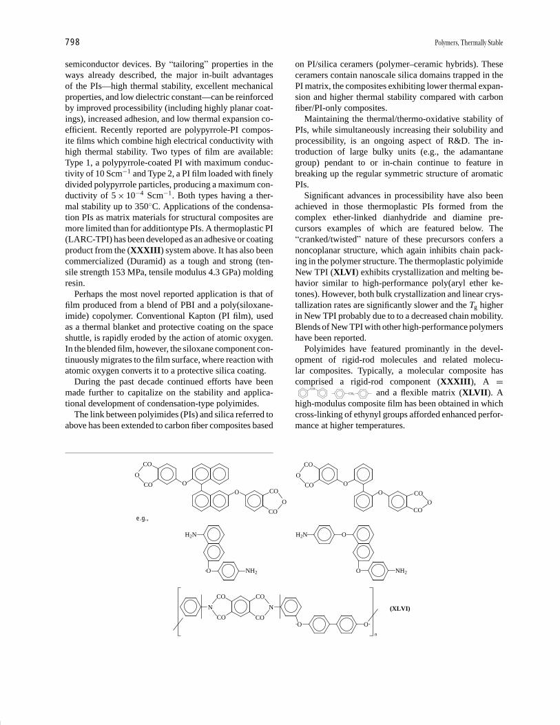
P1: GPQ Final Pages/GNB P2: GTV
Encyclopedia of Physical Science and Technology En012c-604 July 26, 2001 16:2
798 Polymers, Thermally Stable
semiconductor devices. By “tailoring” properties in theways already described, the major in-built advantagesof the PIs—high thermal stability, excellent mechanicalproperties, and low dielectric constant—can be reinforcedby improved processibility (including highly planar coat-ings), increased adhesion, and low thermal expansion co-efficient. Recently reported are polypyrrole-PI compos-ite films which combine high electrical conductivity withhigh thermal stability. Two types of film are available:Type 1, a polypyrrole-coated PI with maximum conduc-tivity of 10 Scm−1 and Type 2, a PI film loaded with finelydivided polypyrrole particles, producing a maximum con-ductivity of 5 × 10⁻⁴ Scm−1. Both types having a ther-mal stability up to 350◦C. Applications of the condensa-tion PIs as matrix materials for structural composites aremore limited than for additiontype PIs. A thermoplastic PI(LARC-TPI) has been developed as an adhesive or coatingproduct from the (XXXIII) system above. It has also beencommercialized (Duramid) as a tough and strong (ten-sile strength 153 MPa, tensile modulus 4.3 GPa) moldingresin.
Perhaps the most novel reported application is that offilm produced from a blend of PBI and a poly(siloxane-imide) copolymer. Conventional Kapton (PI film), usedas a thermal blanket and protective coating on the spaceshuttle, is rapidly eroded by the action of atomic oxygen.In the blended film, however, the siloxane component con-tinuously migrates to the film surface, where reaction withatomic oxygen converts it to a protective silica coating.
During the past decade continued efforts have beenmade further to capitalize on the stability and applica-tional development of condensation-type polyimides.
The link between polyimides (PIs) and silica referred toabove has been extended to carbon fiber composites based
O CO
OCO
O
CO
O
COO
O
CO
O
COCO
O
CO
O NH2
H2N
.
O
O NH2
H2N
e.g.,
CO
N
CO
CO
COO O
(XLVI)N
n
..
on PI/silica ceramers (polymer–ceramic hybrids). Theseceramers contain nanoscale silica domains trapped in thePI matrix, the composites exhibiting lower thermal expan-sion and higher thermal stability compared with carbonfiber/PI-only composites.
Maintaining the thermal/thermo-oxidative stability ofPIs, while simultaneously increasing their solubility andprocessibility, is an ongoing aspect of R&D. The in-troduction of large bulky units (e.g., the adamantanegroup) pendant to or in-chain continue to feature inbreaking up the regular symmetric structure of aromaticPIs.
Significant advances in processibility have also beenachieved in those thermoplastic PIs formed from thecomplex ether-linked dianhydride and diamine pre-cursors examples of which are featured below. The“cranked/twisted” nature of these precursors confers anoncoplanar structure, which again inhibits chain pack-ing in the polymer structure. The thermoplastic polyimideNew TPI (XLVI) exhibits crystallization and melting be-havior similar to high-performance poly(aryl ether ke-tones). However, both bulk crystallization and linear crys-tallization rates are significantly slower and the Tg higherin New TPI probably due to to a decreased chain mobility.Blends of New TPI with other high-performance polymershave been reported.
Polyimides have featured prominantly in the devel-opment of rigid-rod molecules and related molecu-lar composites. Typically, a molecular composite hascomprised a rigid-rod component (XXXIII), A =
CO
CH2 and a flexible matrix (XLVII). Ahigh-modulus composite film has been obtained in whichcross-linking of ethynyl groups afforded enhanced perfor-mance at higher temperatures.
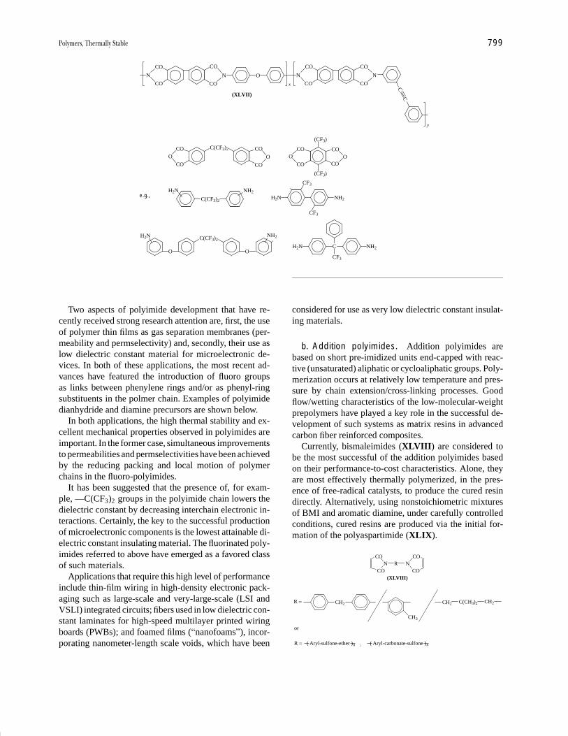
P1: GPQ Final Pages/GNB P2: GTV
Encyclopedia of Physical Science and Technology En012c-604 July 26, 2001 16:2
Polymers, Thermally Stable 799
O
x
CO
N
CO
CO
N
CO
CO
N
CO
CO
N
CO
C
y
C(XLVII)
COO
CO
CO
O
CO
C(CF3)2 COO
CO
COO
CO
(CF3)
(CF3)
CF3
CF3
H2N NH2e.g.,
C
CF3
NH2H2NO
C(CF3)2
O
NH2H2N
C(CF3)2
H2N NH2
Two aspects of polyimide development that have re-cently received strong research attention are, first, the useof polymer thin films as gas separation membranes (per-meability and permselectivity) and, secondly, their use aslow dielectric constant material for microelectronic de-vices. In both of these applications, the most recent ad-vances have featured the introduction of fluoro groupsas links between phenylene rings and/or as phenyl-ringsubstituents in the polmer chain. Examples of polyimidedianhydride and diamine precursors are shown below.
In both applications, the high thermal stability and ex-cellent mechanical properties observed in polyimides areimportant. In the former case, simultaneous improvementsto permeabilities and permselectivities have been achievedby the reducing packing and local motion of polymerchains in the fluoro-polyimides.
It has been suggested that the presence of, for exam-ple, —C(CF3)2 groups in the polyimide chain lowers thedielectric constant by decreasing interchain electronic in-teractions. Certainly, the key to the successful productionof microelectronic components is the lowest attainable di-electric constant insulating material. The fluorinated poly-imides referred to above have emerged as a favored classof such materials.
Applications that require this high level of performanceinclude thin-film wiring in high-density electronic pack-aging such as large-scale and very-large-scale (LSI andVSLI) integrated circuits; fibers used in low dielectric con-stant laminates for high-speed multilayer printed wiringboards (PWBs); and foamed films (“nanofoams”), incor-porating nanometer-length scale voids, which have been
considered for use as very low dielectric constant insulat-ing materials.
b. Addition polyimides. Addition polyimides arebased on short pre-imidized units end-capped with reac-tive (unsaturated) aliphatic or cycloaliphatic groups. Poly-merization occurs at relatively low temperature and pres-sure by chain extension/cross-linking processes. Goodflow/wetting characteristics of the low-molecular-weightprepolymers have played a key role in the successful de-velopment of such systems as matrix resins in advancedcarbon fiber reinforced composites.
Currently, bismaleimides (XLVIII) are considered tobe the most successful of the addition polyimides basedon their performance-to-cost characteristics. Alone, theyare most effectively thermally polymerized, in the pres-ence of free-radical catalysts, to produce the cured resindirectly. Alternatively, using nonstoichiometric mixturesof BMI and aromatic diamine, under carefully controlledconditions, cured resins are produced via the initial for-mation of the polyaspartimide (XLIX).
CN
C
OR
CON
CO
(XLVIII)
R = CH2
CH3
CH2 C(CH3)2 CH2
O
or
R = ( Aryl-sulfone-ether )n ; ( Aryl-carbonate-sulfone )n
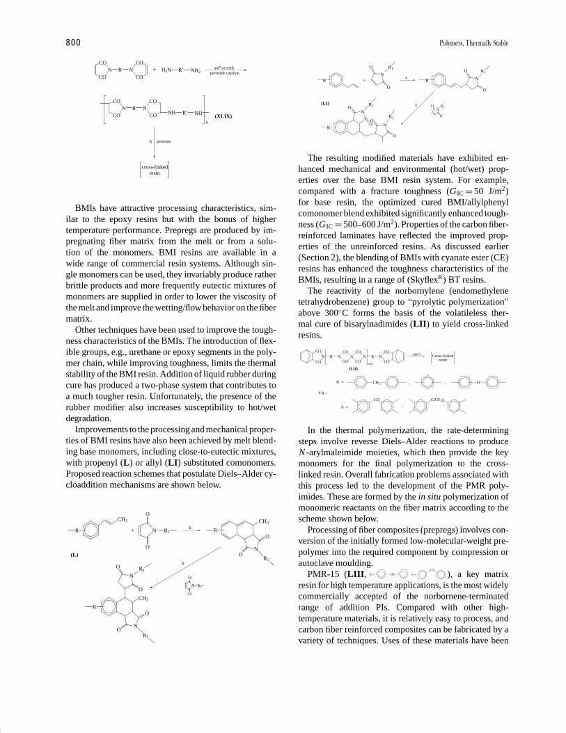
P1: GPQ Final Pages/GNB P2: GTV
Encyclopedia of Physical Science and Technology En012c-604 July 26, 2001 16:2
800 Polymers, Thermally Stable
CN
COR
CON
COH2N R′ NH2
soln or meltperoxide catalyst
CN R
CON
CO
NH R′ NH
pressure
cross-linkedresin
∆
(XLIX)
O
+
O
CO
n
BMIs have attractive processing characteristics, sim-ilar to the epoxy resins but with the bonus of highertemperature performance. Prepregs are produced by im-pregnating fiber matrix from the melt or from a solu-tion of the monomers. BMI resins are available in awide range of commercial resin systems. Although sin-gle monomers can be used, they invariably produce ratherbrittle products and more frequently eutectic mixtures ofmonomers are supplied in order to lower the viscosity ofthe melt and improve the wetting/flow behavior on the fibermatrix.
Other techniques have been used to improve the tough-ness characteristics of the BMIs. The introduction of flex-ible groups, e.g., urethane or epoxy segments in the poly-mer chain, while improving toughness, limits the thermalstability of the BMI resin. Addition of liquid rubber duringcure has produced a two-phase system that contributes toa much tougher resin. Unfortunately, the presence of therubber modifier also increases susceptibility to hot/wetdegradation.
Improvements to the processing and mechanical proper-ties of BMI resins have also been achieved by melt blend-ing base monomers, including close-to-eutectic mixtures,with propenyl (L) or allyl (LI) substituted comonomers.Proposed reaction schemes that postulate Diels–Alder cy-cloaddition mechanisms are shown below.
R
CH3
+ N
O
O
R1∆ R
N
O
OR1
N
O
O
R
CH3
N
O
R1
N
O
O
R1
∆
CH3
R1
O
(L)
R +N
O
O
R1
∆R N
O
O
R1
R
NO
R1
NO
R1
O
∆N
O
O
R1(LI)
O
The resulting modified materials have exhibited en-hanced mechanical and environmental (hot/wet) prop-erties over the base BMI resin system. For example,compared with a fracture toughness (GIC = 50 J/m2)for base resin, the optimized cured BMI/allylphenylcomonomer blend exhibited significantly enhanced tough-ness (GIC = 500–600 J/m2). Properties of the carbon fiber-reinforced laminates have reflected the improved prop-erties of the unreinforced resins. As discussed earlier(Section 2), the blending of BMIs with cyanate ester (CE)resins has enhanced the toughness characteristics of theBMIs, resulting in a range of (SkyflexR) BT resins.
The reactivity of the norbornylene (endomethylenetetrahydrobenzene) group to “pyrolytic polymerization”above 300◦C forms the basis of the volatileless ther-mal cure of bisarylnadimides (LII) to yield cross-linkedresins.
CN
CO
OR N
CO
COA
CO
CON R
n=2
NC
C
O
O
>300°C Cross-linkedresin
(LII)
R = CH2 O
A =
CO C(CF3)2
, ,
,
e.g.,
In the thermal polymerization, the rate-determiningsteps involve reverse Diels–Alder reactions to produceN -arylmaleimide moieties, which then provide the keymonomers for the final polymerization to the cross-linked resin. Overall fabrication problems associated withthis process led to the development of the PMR poly-imides. These are formed by the in situ polymerization ofmonomeric reactants on the fiber matrix according to thescheme shown below.
Processing of fiber composites (prepregs) involves con-version of the initially formed low-molecular-weight pre-polymer into the required component by compression orautoclave moulding.
PMR-15 (LIII, CH2 A =CO
=R ), a key matrixresin for high temperature applications, is the most widelycommercially accepted of the norbornene-terminatedrange of addition PIs. Compared with other high-temperature materials, it is relatively easy to process, andcarbon fiber reinforced composites can be fabricated by avariety of techniques. Uses of these materials have been
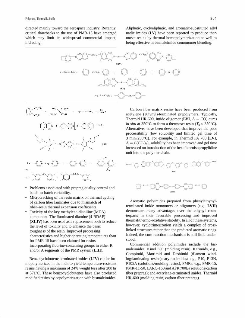
P1: GPQ Final Pages/GNB P2: GTV
Encyclopedia of Physical Science and Technology En012c-604 July 26, 2001 16:2
Polymers, Thermally Stable 801
directed mainly toward the aerospace industry. Recently,critical drawbacks to the use of PMR-15 have emergedwhich may limit its widespread commercial impact,including:
CON
CO
C(CF3)2N
CO
CO
ArCO
NCO
C(CF3)2
n
N
CO
CO
(LIV)
n = 0 or n = 1, Ar = C(CF3)2 ; ; ; O
N
CO
CO
R N
CO
CO(LV)
e.g., R = (CH2)6 CH2;
� Problems associated with prepreg quality control andbatch-to-batch variability.
� Microcracking of the resin matrix on thermal cyclingof carbon fiber laminates due to mismatch offiber–resin thermal expansion coefficients.
� Toxicity of the key methylene-dianiline (MDA)component. The fluorinated diamine (4-BDAF)(XLIV) has been used as a replacement both to reducethe level of toxicity and to enhance the basictoughness of the resin. Improved processingcharacteristics and higher operating temperatures thanfor PMR-15 have been claimed for resinsincorporating fluorine-containing groups in either Rand/or A segments of the PMR system (LIII).
Benzocyclobutene terminated imides (LIV) can be ho-mopolymerized in the melt to yield temperature-resistantresins having a maximum of 24% weight loss after 200 hrat 371◦C. These benzocyclobutenes have also producedmodified resins by copolymerization with bismaleimides.
Aliphatic, cycloaliphatic, and aromatic-substituted allylnadic imides (LV) have been reported to produce ther-moset resins by thermal homopolymerization as well asbeing effective in bismaleimide comonomer blending.
Carbon fiber matrix resins have been produced fromacetylene (ethynyl)-terminated prepolymers. Typically,Thermid HR 600, imide oligomer (LVI, A = CO) curesin situ at 350◦C to form a thermoset resin (Tg > 350◦C).Alternatives have been developed that improve the poorprocessibility (low solubility and limited gel time of3 min /250◦C). For example, in Thermid FA 700 [LVI,A = C(CF3)2], solubility has been improved and gel timeincreased on introduction of the hexafluoroisopropylidineunit into the polymer chain.
N
CO
CON
CO
COAO O
N
CO
CO
A C CH
(LVI)
HC C
C CN
CO
CO
O N
CO
CO
(LVII)
C C
Aromatic polyimides prepared from phenylethynyl-terminated imide monomers or oligomers (e.g., LVII)demonstate many advantages over the ethynyl coun-terparts in their favorable processing and improvedthermal/thermo-oxidative stability. In all of these systems,however, cyclotrimerization yields a complex of cross-linked structures rather than the predicted aromatic rings.Indeed, the cure reaction mechanism is still little under-stood.
Commercial addition polyimides include the bis-maleimides: Kinel 500 (molding resin), Kerimids, e.g.,Compimid, Matrimid and Desbimid (filament wind-ing/laminating resins); arylnadimides: e.g., P10, P13N,P105A (solutions/molding resins); PMRs: e.g., PMR-15,PMR-11-50, LARC-160 and AFR 700B (solutions/carbonfiber prepreg); and acetylene-terminated imides. ThermidHR-600 (molding resin, carbon fiber prepreg).
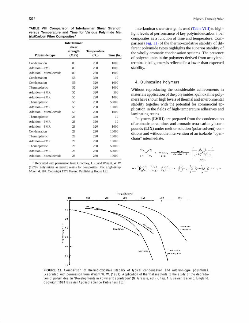
P1: GPQ Final Pages/GNB P2: GTV
Encyclopedia of Physical Science and Technology En012c-604 July 26, 2001 16:2
802 Polymers, Thermally Stable
TABLE VIII Comparison of Interlaminar Shear Strengthversus Temperature and Time for Various Polyimide Ma-trix/Carbon Fiber Compositesa
Interlaminarshear
strength TemperaturePolyimide type (MPa) (◦C) Time (hr)
Condensation 83 260 1000
Addition—PMR 83 260 1000
Addition—bismaleimide 83 230 1000
Condensation 55 350 10
Condensation 55 320 1000
Thermoplastic 55 320 1000
Addition—PMR 55 320 500
Addition—PMR 55 290 1000
Thermoplastic 55 260 50000
Addition—PMR 55 260 10000
Addition—bismaleimide 55 260 1000
Thermoplastic 28 350 10
Addition—PMR 28 350 10
Addition—PMR 28 320 1000
Condensation 28 290 10000
Thermoplastic 28 290 10000
Addition—PMR 28 290 10000
Thermoplastic 28 230 50000
Addition—PMR 28 230 50000
Addition—bismaleimide 28 230 10000
a Reprinted with permission from Critchley, J. P., and Wright, W. W.(1979). Polyimides as matrix resins for composites, Rev. High-Temp.Mater. 4, 107. Copyright 1979 Freund Publishing House Ltd.
FIGURE 11 Comparison of thermo-oxidative stability of typical condensation and addition-type polyimides.[Reprinted with permission from Wright W. W. (1981). Application of thermal methods to the study of the degrada-tion of polyimides. In “Developments in Polymer Degradation” (N. Grassie, ed.), Chap. 1. Elsevier, Barking, England.Copyright 1981 Elsevier Applied Science Publishers Ltd.]
Interlaminar shear strength is used (Table VIII) to high-light levels of performance of key polyimide/carbon fibercomposites as a function of time and temperature. Com-parison (Fig. 11) of the thermo-oxidative stability of dif-ferent polyimide types highlights the superior stability ofthe wholly aromatic condensation systems. The presenceof polyene units in the polymers derived from acetylene-terminated oligomers is reflected in a lower-than-expectedstability.
4. Quinoxaline Polymers
Without reproducing the considerable achievements inmaterials application of the polyimides, quinoxaline poly-mers have shown high levels of thermal and environmentalstability together with the potential for commercial ap-plication in the fields of high-temperature adhesives andlaminating resins.
Polymers (LVIII) are prepared from the condensationof aromatic tetraamines and aromatic tetra-carbonyl com-pounds (LIX) under melt or solution (polar solvent) con-ditions and without the intervention of an isolable “open-chain” intermediate.
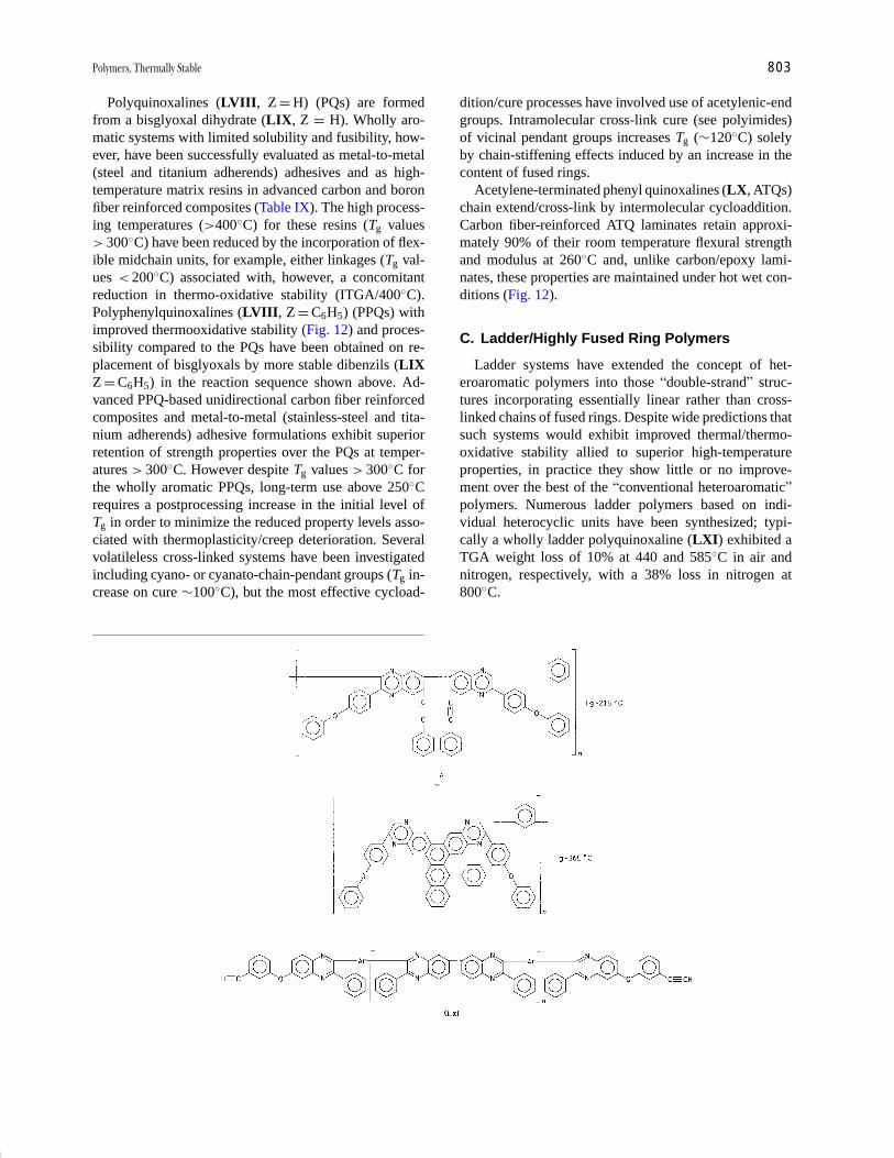
P1: GPQ Final Pages/GNB P2: GTV
Encyclopedia of Physical Science and Technology En012c-604 July 26, 2001 16:2
Polymers, Thermally Stable 803
Polyquinoxalines (LVIII, Z = H) (PQs) are formedfrom a bisglyoxal dihydrate (LIX, Z = H). Wholly aro-matic systems with limited solubility and fusibility, how-ever, have been successfully evaluated as metal-to-metal(steel and titanium adherends) adhesives and as high-temperature matrix resins in advanced carbon and boronfiber reinforced composites (Table IX). The high process-ing temperatures (>400◦C) for these resins (Tg values> 300◦C) have been reduced by the incorporation of flex-ible midchain units, for example, either linkages (Tg val-ues < 200◦C) associated with, however, a concomitantreduction in thermo-oxidative stability (ITGA/400◦C).Polyphenylquinoxalines (LVIII, Z = C6H5) (PPQs) withimproved thermooxidative stability (Fig. 12) and proces-sibility compared to the PQs have been obtained on re-placement of bisglyoxals by more stable dibenzils (LIXZ = C6H5) in the reaction sequence shown above. Ad-vanced PPQ-based unidirectional carbon fiber reinforcedcomposites and metal-to-metal (stainless-steel and tita-nium adherends) adhesive formulations exhibit superiorretention of strength properties over the PQs at temper-atures > 300◦C. However despite Tg values > 300◦C forthe wholly aromatic PPQs, long-term use above 250◦Crequires a postprocessing increase in the initial level ofTg in order to minimize the reduced property levels asso-ciated with thermoplasticity/creep deterioration. Severalvolatileless cross-linked systems have been investigatedincluding cyano- or cyanato-chain-pendant groups (Tg in-crease on cure ∼100◦C), but the most effective cycload-
dition/cure processes have involved use of acetylenic-endgroups. Intramolecular cross-link cure (see polyimides)of vicinal pendant groups increases Tg (∼120◦C) solelyby chain-stiffening effects induced by an increase in thecontent of fused rings.
Acetylene-terminated phenyl quinoxalines (LX, ATQs)chain extend/cross-link by intermolecular cycloaddition.Carbon fiber-reinforced ATQ laminates retain approxi-mately 90% of their room temperature flexural strengthand modulus at 260◦C and, unlike carbon/epoxy lami-nates, these properties are maintained under hot wet con-ditions (Fig. 12).
C. Ladder/Highly Fused Ring Polymers
Ladder systems have extended the concept of het-eroaromatic polymers into those “double-strand” struc-tures incorporating essentially linear rather than cross-linked chains of fused rings. Despite wide predictions thatsuch systems would exhibit improved thermal/thermo-oxidative stability allied to superior high-temperatureproperties, in practice they show little or no improve-ment over the best of the “conventional heteroaromatic”polymers. Numerous ladder polymers based on indi-vidual heterocyclic units have been synthesized; typi-cally a wholly ladder polyquinoxaline (LXI) exhibited aTGA weight loss of 10% at 440 and 585◦C in air andnitrogen, respectively, with a 38% loss in nitrogen at800◦C.
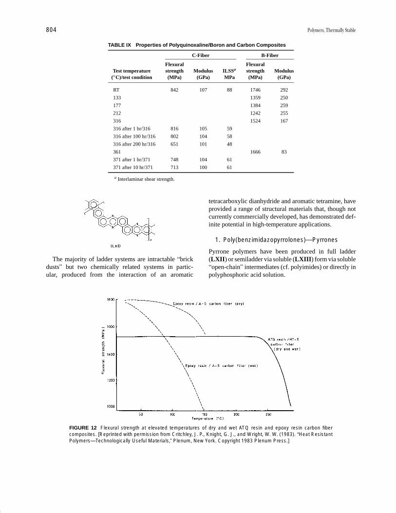
P1: GPQ Final Pages/GNB P2: GTV
Encyclopedia of Physical Science and Technology En012c-604 July 26, 2001 16:2
804 Polymers, Thermally Stable
TABLE IX Properties of Polyquinoxaline/Boron and Carbon Composites
C-Fiber B-Fiber
Flexural FlexuralTest temperature strength Modulus ILSSa strength Modulus
(◦C)/test condition (MPa) (GPa) MPa (MPa) (GPa)
RT 842 107 88 1746 292
133 1359 250
177 1384 259
212 1242 255
316 1524 167
316 after 1 hr/316 816 105 59
316 after 100 hr/316 802 104 58
316 after 200 hr/316 651 101 48
361 1666 83
371 after 1 hr/371 748 104 61
371 after 10 hr/371 713 100 61
a Interlaminar shear strength.
The majority of ladder systems are intractable “brickdusts” but two chemically related systems in partic-ular, produced from the interaction of an aromatic
FIGURE 12 Flexural strength at elevated temperatures of dry and wet ATQ resin and epoxy resin carbon fibercomposites. [Reprinted with permission from Critchley, J. P., Knight, G. J., and Wright, W. W. (1983). “Heat ResistantPolymers—Technologically Useful Materials,” Plenum, New York. Copyright 1983 Plenum Press.]
tetracarboxylic dianhydride and aromatic tetramine, haveprovided a range of structural materials that, though notcurrently commercially developed, has demonstrated def-inite potential in high-temperature applications.
1. Poly(benzimidazopyrrolones)—Pyrrones
Pyrrone polymers have been produced in full ladder(LXII) or semiladder via soluble (LXIII) form via soluble“open-chain” intermediates (cf. polyimides) or directly inpolyphosphoric acid solution.
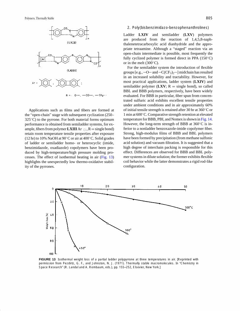
P1: GPQ Final Pages/GNB P2: GTV
Encyclopedia of Physical Science and Technology En012c-604 July 26, 2001 16:2
Polymers, Thermally Stable 805
Applications such as films and fibers are formed atthe “open-chain” stage with subsequent cyclization (250–325◦C) to the pyrrone. For both material forms optimumperformance is obtained from semiladder systems, for ex-ample, fibers from polymer LXIII Ar , R = single bond)retain room temperature tensile properties after exposure(12 hr) to 10% NaOH at 90◦C or air at 400◦C. Solid gradesof ladder or semiladder homo- or heterocyclic (imide,benzimidazole, oxadiazole) copolymers have been pro-duced by high-temperature/high pressure molding pro-cesses. The effect of isothermal heating in air (Fig. 13)highlights the unexpectedly low thermo-oxidative stabil-ity of the pyrrones.
FIGURE 13 Isothermal weight loss of a partial ladder polypyrrone at three temperatures in air. [Reprinted withpermission from Pezdirtz, G. F., and Johnston, N. J. (1971). Thermally stable macromolecules. In “Chemistry inSpace Research” (R. Landal and A. Rembaum, eds.), pp. 155–252, Elsevier, New York.]
2. Poly(bisbenzimidazo-benzophenanthrolines)
Ladder LXIV and semiladder (LXV) polymersare produced from the reaction of 1,4,5,8-naph-thalenetetracarboxylic acid dianhydride and the appro-priate tetraamine. Although a “staged” reaction via anopen-chain intermediate is possible, most frequently thefully cyclized polymer is formed direct in PPA (150◦C)or in the melt (300◦C).
For the semiladder system the introduction of flexiblegroups [e.g., O and C(CF3)2 ] midchain has resultedin an increased solubility and tractability. However, formost practical applications, ladder system (LXIV) andsemiladder polymer (LXV; R = single bond), so calledBBL and BBB polymers, respectively, have been widelyevaluated. For BBB in particular, fiber spun from concen-trated sulfuric acid exhibits excellent tensile propertiesunder ambient conditions and in air approximately 60%of initial tensile strength is retained after 30 hr at 360◦C or1 min at 600◦C. Comparative strength retention at elevatedtemperature for BBB, PBI, and Nomex is shown in Fig. 14.However, the long-term strength of BBB at 360◦C is in-ferior to a nonladder benzoxazole-imide copolymer fiber.Strong, high-modulus films of BBB and BBL polymershave been formed by precipitation (from methane sulfonicacid solution) and vacuum filtration. It is suggested that ahigh degree of interchain packing is responsible for thiseffect. Differences are observed for BBB and BBL poly-mer systems in dilute solution; the former exhibits flexiblecoil behavior while the latter demonstrates a rigid rod-likeconfiguration.
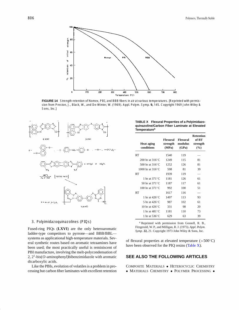
P1: GPQ Final Pages/GNB P2: GTV
Encyclopedia of Physical Science and Technology En012c-604 July 26, 2001 16:2
806 Polymers, Thermally Stable
FIGURE 14 Strength retention of Nomex, PBI, and BBB fibers in air at various temperatures. [Reprinted with permis-sion from Preston, J., Black, W., and De-Winter, W. (1969). Appl. Polym. Symp. 9, 145. Copyright 1969 John Wiley &Sons, Inc.]
3. Polyimidazoquinazolines (PIQs)
Fused-ring PIQs (LXVI) are the only heteroaromaticladder-type competitors to pyrrone—and BBB/BBL—systems as applicational high-temperature materials. Sev-eral synthetic routes based on aromatic tetraamines havebeen used; the most practically useful is reminiscent ofPBI manufacture, involving the melt-polycondensation of2, 21-bis(O-aminophenyl)bibenzimidazole with aromaticdicarboxylic acids.
Like the PBIs, evolution of volatiles is a problem in pro-cessing but carbon fiber laminates with excellent retention
TABLE X Flexural Properties of a Polyimidazo-quinazoline/Carbon Fiber Laminate at ElevatedTemperaturea
RetentionFlexural Flexural of RT
Heat aging strength modulus strengthconditions (MPa) (GPa) (%)
RT 1540 119 —
200 hr at 316◦C 1249 115 81
500 hr at 316◦C 1252 126 81
1000 hr at 316◦C 598 81 39
RT 1939 119 —
1 hr at 371◦C 1181 126 61
50 hr at 371◦C 1187 117 61
100 hr at 371◦C 992 100 51
RT 1617 116 —
1 hr at 426◦C 1497 113 93
5 hr at 426◦C 987 102 61
10 hr at 426◦C 331 98 20
1 hr at 481◦C 1181 110 73
1 hr at 536◦C 629 63 39
a Reprinted with permission from Gosnell, R. B.,Fitzgerald, W. P., and Milligan, R. J. (1973). Appl. Polym.Symp. 22, 21. Copyright 1973 John Wiley & Sons, Inc.
of flexural properties at elevated temperature (>500◦C)have been observed for the PIQ resins (Table X).
SEE ALSO THE FOLLOWING ARTICLES
COMPOSITE MATERIALS • HETEROCYCLIC CHEMISTRY
• MATERIALS CHEMISTRY • POLYMER PROCESSING •
P1: GPQ Final Pages/GNB P2: GTV
Encyclopedia of Physical Science and Technology En012c-604 July 26, 2001 16:2
Polymers, Thermally Stable 807
POLYMERS, INORGANIC AND ORGANOMETALLIC • POLY-MERS, MECHANICAL BEHAVIOR
BIBLIOGRAPHY
Akita, H., et al. (1999). J. Polym. Sci. Polym. Phys. 37, 199–207, 209–218.
Auman, B. C., Myers, T. L., and Higley, D. P. (1997). J. Polym. Sci.Polym. Chem. 35(12), 2441.
Beehag, A., and Ye, L. (1996). Composites 27A, 175.Ching, T.-S., and Kafchinski, E. R. (1996). Polymer 37(9), 1635.Coleman, M. R., and Koros, W. J. (1994). The transport properties of
polyimide isomers containing hexafluoroisopropylidine in the diamineresidue. J. Polym. Sci. Polym. Phys. 32(11), 1915.
Critchley, J. P., Knight, G. J., and Wright, W. W. (1983). “Heat ResistantPolymers—Technologically Useful Materials,” Plenum, New York.
Eashoo, M., Buckley, L. J., and St. Clair, A. K. (1997). J. Polym. Sci.Polym. Phys. 35(1), 173.
Ghosh, M., and Mittal, K. L., eds. (1996). “Polyimides: Fundamentalsand Applications,” Marcel Dekker, New York.
Goodwin, A. A. (1999). Thermal properties of a thermoplastic polyimideblend. J. Appl. Polym. Sci. 72, 543.
Grenier-Loustalot, M. F., Billon, L., Louartani, A., et al. (1997). Polym.Int. 44(4), 435.
Hamerton, I., ed. (1994). “Chemistry and Technology of Cyanate EsterResins,” Blackie Academic and Professional, Glasgow, UK.
Han, J. L., and Li, K. Y. (1998). J. Appl. Polym. Sci. 70(13), 2635.Hedrick, J. L., Di Pietro, R., and Plummer, C. J. G., et al. (1996). Polymer
37, 5229.Ivanov, D. A., and Jones, A. M. (1998). J. Polym. Sci. Polym. Phys. 36(5),
39.Kitagawa, T., Murase, H., and Yabuki, K. (1998). J. Polym. Sci. Polym.
Phys. 36(1), 39.Lovinger, A. J., Padden, F. J., and Davis, D. D. (1998). Crystal struc-
ture, morphology, thermal stability and crystallization kinetics of PPS.Polymer 29, 229.
Mascia, L., Zhang, Z., and Shaw, S. J. (1996). Composites 27A, 1211.McGee, R. L., et al. (1997). J. Polym. Sci. Polym. Chem. 35(11),
2157.Pater, R. H. (1994). SAMPE J. 30, 29.So, Y.-H., et al. (1995). J. Polym. Sci. Polym. Chem. 33(15), 2893.Song, H.-H. (1999). J. Polym. Sci. Polym. Phys. 37(7), 661.Susuki, A., Kohno, T., and Kunugi, T. (1998). J. Polym. Sci. Polym. Phys.
36(10), 1731.Toi, K., Tsuzumi, H., and Ito, T. (1999). Polym. Polym. Compo. 7(1), 45.Zoia, G., et al. (1994). J. Polym. Sci. Polym. Phys. 32(1), 53.
P1: GQT/MBQ P2: GPJ Final Pages Qu: 00, 00, 00, 00
Encyclopedia of Physical Science and Technology EN014C-660 July 28, 2001 17:14
Rheology of Polymeric LiquidsChang Dae HanUniversity of Akron
I. Classification of Polymeric LiquidsII. Unusual Characteristics of Polymeric Liquid Flow
III. Definitions of Material Functions for PolymericLiquids
IV. Methods for Determining Rheological Propertiesof Polymeric Liquids
V. Constitutive Equations for Predicting theRheological Properties of Polymeric Liquids
VI. Concluding Remarks
GLOSSARY
Dynamic viscosity Real component of complex viscosityin oscillatory shear flow.
Extrudate swell Swelling of extrudate upon exiting froma die.
Loss modulus Imaginary component of the complexmodulus.
Normal stress difference Difference in the two primarynormal stresses.
Normal stress effect Effect exhibiting the elasticity ofpolymeric liquid.
Shear thinning behavior Decreasing trend of viscositywith increasing shear rate.
Shear viscosity Viscosity in steady-state shear flow.Storage modulus Real component of the complex
modulus.
RHEOLOGY is the science of the deformation and flowof matter. Therefore, depending on the type of matter
one deals with, different branches of rheology may beconsidered. For instance, polymer rheology deals withpolymeric materials and biorheology deals with biologicalfluids (e.g., blood, mucus, and synovial fluids). Polymericmaterials cover a wide range of man-made materials, suchas plastics, synthetic rubber, synthetic fiber, and many oth-ers. These materials have very large molecules consistingof many repeat units of small molecules. Because of thelarge size of the molecules, they exhibit unusual flow be-havior under deformation. The study of the flow behaviorof polymeric liquids is not only an intellectual challengeto scientists, but also is of fundamental importance to anadvancement of polymer technology.
I. CLASSIFICATION OFPOLYMERIC LIQUIDS
In a general sense, there are two types of polymeric liquids:thermoplastics and thermosets. Thermoplastic polymericliquids are thermally reversible in that, when solidified,
Encyclopedia of Physical Science and Technology, Third Edition, Volume 14Copyright C© 2002 by Academic Press. All rights of reproduction in any form reserved. 237

P1: GQT/MBQ P2: GPJ Final Pages
Encyclopedia of Physical Science and Technology EN014C-660 July 28, 2001 17:14
238 Rheology of Polymeric Liquids
they can be melted by heating to recover the original liquidstate. Thermoset resins, in contrast, are thermally irre-versible in that, once solidified, they cannot be melted.Thermoplastic polymer molecules are large, with molec-ular weights on the order of tens to hundreds of thousands.Furthermore, many of the repeat units are linked ina one-dimensional direction. The size of thermoplasticpolymer molecules does not change during the fabricationof products. Thermoplastic polymers (e.g., polyethylene,polystyrene, poly(vinyl chloride), nylon, and polycarbon-ate) are used for manufacturing films, fibers, furniture,etc. Thermoset resins, however, have smaller molecules,with molecular weights on the order of a few thousand.They usually form three-dimensional networks in the pres-ence of a catalyst (often referred to as curing agent), giv-ing rise to strong structures. Therefore, parts made fromthermoset resins are much stronger than those made fromthermoplastic polymers and are widely used for structuralpurposes. Thermoset resins (e.g., unsaturated polyester,epoxy, and urethane) are used for manufacturing boathulls, parts for automobiles and airplanes, bath tubs, but-tons, etc.
Thus, in dealing with the flow properties of thermoplas-tic polymeric liquids, one need not be concerned with achange of molecular size, and in this sense, the measure-ment of the flow properties of thermoplastic polymericliquids is much simpler than that of thermoset resins. Indealing with the flow properties of thermoset resins, how-ever, one must understand that the molecules grow dur-ing fabrication. Consequently, measurement of the flowproperties of thermoset resins is very difficult. An under-standing of the flow behavior of thermoset resins duringfabrication requires an understanding of the nature of thechemical reactions occurring during fabrication. Becauseof the complexity of the problems involved in dealing withthe rheological behavior of thermoset resins, we shall be
FIGURE 1 Photograph describing the liquid climb-up effect: (1) low-molecular-weight polybutene; (b) 2 wt% aqueoussolution of polyacrylamide.
concerned here primarily with the rheological behavior ofthermoplastic polymeric liquids.
Thermoplastic polymeric materials may be classified inthe following way, on the basis of chemical constituents:(1) bulk polymers (or polymer solutions), which are con-sidered to be homogeneous liquids; (2) polymer liquidcrystals; (3) polymer blends consisting of two or moresimilar or dissimilar polymers, the latter of which gener-ally form heterogeneous phases in which one componentis suspended in the other; (4) filled polymers in whichparticulates are suspended in the polymeric liquid; and(5) polymeric foams, in which gas bubbles are suspendedin the polymeric liquid.
II. UNUSUAL CHARACTERISTICSOF POLYMERIC LIQUID FLOW
Before we quantitatively discuss the rheological behaviorof polymeric liquids, let us observe some of their unusualflow characteristics. Figure 1 demonstrates a dramaticdifference between two types of liquid—a low-mole-cular-weight polybutene and an aqueous solution ofpolyacrylamide—when a rotating rod is dipped into them.The polyacrylamide solution climbs up the rotating rod,while the low-molecular-weight polybutene does not.Note that low-molecular-weight polybutene has a molec-ular weight of hundreds or thousands, whereas the poly-acrylamide dissolved in water is believed to have a molec-ular weight of tens of thousands.
The direction in which the polyacrylamide solutionclimbs in Fig. 1 is perpendicular to the rotating direc-tion of the solution, and therefore one can conjecture thatthere ought to be a force generated by the liquid that over-comes the effect of centrifugal force and points in a direc-tion perpendicular to the direction of rotation. The liquid

P1: GQT/MBQ P2: GPJ Final Pages
Encyclopedia of Physical Science and Technology EN014C-660 July 28, 2001 17:14
Rheology of Polymeric Liquids 239
FIGURE 2 Photograph describing the swelling of a molten high-density polyethylene melt at 180◦C exiting from acylindrical tube.
climb-up effect shows that polymeric liquids exhibit a“normal stress” effect.
Figure 2 shows the swelling of a molten high-densitypolyethylene extrudate exiting from a cylindrical tube,which is believed to occur as a result of the recovery of theelastic deformation (or the relaxation of normal stresses)imposed on the polymeric liquid in the capillary.
III. DEFINITIONS OF MATERIALFUNCTIONS FOR POLYMERIC LIQUIDS
Consider the flow fields in which a polymeric liquid canundergo shear deformation, which is encountered whenthe liquid flows through a confined geometry, such asthrough a pipe or channel. Under such circumstances,some practical questions come to mind. (1) How muchpressure drop (or mechanical or electrical power) are re-quired to maintain liquid flow through a pipe at a desiredflow rate? (2) What would be the most cost-effective de-sign for a pipe to transport a specific polymeric liquid at adesired flow rate? These questions can be answered intel-ligently only when we know the relationships between therheological properties of the liquid and the rate of defor-mation and between the rheological properties of the liquidand its molecular parameters, such as the chemical struc-ture, molecular weight, and molecular weight distribution.
Consider a flow of liquid flowing through two infinitelylong parallel planes, where the upper plane moves in thez direction at a constant velocity V (i.e., vz = V ) at y = hwhile the lower plane remains stationary (i.e., vz = 0). Re-ferring to Fig. 3, the gap opening h is very small comparedto the width w of the plane (i.e., h � w). Under such asituation, the velocity field of the flow at steady state be-tween the two planes is given by
vz = f (y), vx = vy = 0. (1)
We then have a constant velocity gradient dvz/dy,
γ = dvz/dy = constant, (2)
where γ is called steady-state shear rate. The flow fieldsatisfying Eq. (1) is called “uniform shear” flow field or“simple shear” flow field.
When a liquid flowing through a long cylindrical tube,the velocity profile of the liquid may look like that shownin Fig. 4. The exact shape of the parabolic velocity pro-file may vary depending on the type of liquid dealt with;in other words, whether the liquid has small moleculesor large molecules. The shape of the velocity profile canbe predicted only when we have information on the flowproperties of the liquid. It is clear from Fig. 4 that the axialvelocity vz is a function only of distance in the radial (r )direction in cylindrical coordinates, that is,
vz = f (r ), (3)
and therefore the velocity gradient dvz/dr varies with r ,
FIGURE 3 Schematic describing the velocity profile of a liquidflowing through two parallel planes.

P1: GQT/MBQ P2: GPJ Final Pages
Encyclopedia of Physical Science and Technology EN014C-660 July 28, 2001 17:14
240 Rheology of Polymeric Liquids
FIGURE 4 Schematic describing the velocity profile of a liquidflowing through a cylindrical tube.
dvz/dr = g(r ). (4)
The flow field given by Eq. (4) is called “nonuniformshear” flow field. We can show that the velocity profileof a polymeric liquid may be given by
vz(r ) = V
(3n + 1
n + 1
) [1 −
(r
R
)(n+1)/n]
, (5)
where V is the average velocity, R is the radius of the tube,and n is a constant characteristic of the liquid. It can beshown easily that for n = 1, Eq. (5) reduces to
vz(r ) = 2V
[1 −
(r
R
)2]
. (6)
It is well-established that the majority of polymeric liq-uids have values of n less than unity. We describe laterhow one can determine experimentally the values of n forpolymeric liquids.
Let us consider the three forces acting on the three faces(one force on each face) of a small cube element of fluid,schematically shown in Fig. 5. For instance, a force actingon face ABCD with an arbitrary direction may be resolvedinto three-component directions: the force acting in the x1
direction is S11dx1dx3, the force acting in the x2 direc-tion is S12dx2dx3, and the force acting in the x3 directionis S13dx2dx3. Similarly, the forces acting on face BCFEare S21dx1dx3 in the x1 direction, S22dx1dx3 in the x2 di-rection, and S23dx1dx3 in the x3 direction. Likewise, theforces acting on face DCFG are S31dx1dx2 in the x1 direc-tion, S32dx1dx2 in the x2 direction, and S33dx1dx2 in thex3 direction. Therefore, we may represent the componentsof the stress tensor Si j in matrix form as
S =
∥∥∥∥∥∥∥S11 S12 S13
S21 S22 S23
S31 S32 S33
∥∥∥∥∥∥∥, (7)
FIGURE 5 Stress components on a cube.
where the component Si j of the stress tensor S is the forceacting in the x j direction on the unit area of a surfacenormal to the xi direction. The components S11, S22, andS33 are called normal stresses since they act normally(or perpendicular) to surfaces, and the mixed componentsS12, S13, etc., are called shear stresses.
If a liquid has been at rest for a sufficiently long time,there are no tangential components of stress on any planeof a cube and the normal components of stress are the samefor all three planes, each perpendicular to the others. Insuch a situation, the normal component of stress is nothingbut hydrostatic pressure. However, when a liquid is underdeformation or in flow, additional stresses are generated.The components of the stresses may be divided into twoparts and, in Cartesian coordinates, we have
Si j = −pδi j + σi j . (8)
In Eq. (8), p is the hydrostatic pressure, and it has a neg-ative sign since it acts in a direction opposite to a normalstress (S11, S22, S33) which, for convenience, is chosen aspointing out of the cube (Fig. 5). The σi j term is the i j thcomponent of the extra stress that arises due to the defor-mation of the liquid, and the subscripts i and j , respec-tively, range from 1 to 3.
If we now consider the state of stress in an isotropicmaterial subjected to simple shear flow defined by Eq. (2),we have
S13 = S31 = S23 = S32 = 0, S12 = S21 �= 0. (9)
Since the measurement of hydrostatic pressure is not pos-sible when a liquid is under deformation or in flow, wenow define hydrostatic pressure as
−p = (S11 + S22 + S33)/3 (10)
Using Eqs. (9) and (10) in Eq. (8), we obtain three indepen-dent stress quantities of rheological significance—namely,

P1: GQT/MBQ P2: GPJ Final Pages
Encyclopedia of Physical Science and Technology EN014C-660 July 28, 2001 17:14
Rheology of Polymeric Liquids 241
two differences of normal stress components and one shearcomponent,
N1 = σ11 − σ22, N2 = σ22 − σ33, and σ12, (11)
in which N1 is called the first normal stress difference,N2 is called the second normal stress difference, and σ12
is called the shear stress. Following the nomenclaturesagreed up by the rheology community, hereafter σ insteadof σ12 will be used to denote the shear stress. Note thatσ11 − σ33 becomes redundant since we have
σ11 + σ22 + σ33 = 0, (12)
which follows from Eqs. (8) and (10).Let us now define the following three material functions
of rheological significance in steady-state shear flow:
σ = η(γ )γ , (13)
N1 = �1(γ )γ 2, (14)
N2 = �2(γ )γ 2, (15)
where η (γ ) denotes the shear viscosity function, which isconsidered to be a measure of the resistance to flow, �1 isthe first normal stress difference coefficient, and �2 is thesecond normal stress difference coefficient, with subscript1 denoting the direction of flow, subscript 2 the directionperpendicular to the flow, and subscript 3 the remaining(i.e., neutral) direction. We will show below how the quan-tities, σ, N1, and N2 can experimentally be determined,and how such information can be used to characterize therheological properties of polymeric liquids.
IV. METHODS FOR DETERMININGRHEOLOGICAL PROPERTIESOF POLYMERIC LIQUIDS
There are two basic types of apparatus for determining therheological properties of polymeric liquids in shear flow:the rotational instrument and the capillary instrument. Therotational instrument may have one of three flow geome-tries: cone-and-plate, two parallel plates, or two coaxialcylinders.
Let us consider the flow of a polymeric liquid placed inthe cone-and-plate fixture, in which a cone with a wide ver-tical angle is placed on a horizontal flat plate, as schemat-ically shown in Fig. 6. The wedge-like space between thecone and plate is filled with the liquid under test. One ofthe surfaces is fixed and the other rotates around the axisof the cone. In using such an instrument, we wish to relatethe torque and the net thrust F (in excess of that due toambient pressure) acting on the cone (or plate) to the an-gular velocity �. For an instrument having a small angleθc (e.g., less than 5◦) between the cone and plate (Fig. 6)
FIGURE 6 Schematic describing the cone-and-plate geometry.
and a small gap (say 50 µm) between the cone and plate,one can derive the following expressions for steady-stateshear flow:
γ = −�/θc, (16)
σ = 3/2π R3, (17)
N1 = 2F/π R2, (18)
where γ is the shear rate and R is the radius of the cone.Since we expect that the measured torque and normalforce F will vary with the angular velocity � of the cone(or plate), we should be able to obtain an experimentalcorrelation between σ and γ , and between N1 and γ .
Figure 7 gives logarithmic plots of η versus γ andlogarithmic plots of N1 versus γ for molten polystyreneand poly(methyl methacrylate), respectively, at 200◦C, inwhich the data for γ < 20 sec−1 were obtained using acone-and-plate rheometer and the data for γ < 70 sec−1
were obtained with a slit rheometer that will be discussedbelow. Note in Fig. 7 that the values of η and N1 weredetermined using Eqs. (16) through (18) with the defini-tion of η defined by Eq. (13). Many polymer solutionsand polymer melts exhibit similar rheological behavior insteady-state shear flow as that shown in Fig. 7.
It can be seen in Fig. 7 that η stays constant at low γ andthen starts to decrease as γ is increased further. This be-havior of η can be described by the following expression:
η ={η0, for γ < γc,
K γ n−1, for γ ≥ γc,(19)
where η0 is called the zero-shear viscosity, γc is the criticalshear rate at which η starts to decrease as γ is increasedbeyond that value, K is the power-law constant, and nis the power-law index. One can determine values of Kand n from log σ versus log γ plots in the shear-thinningregion (i.e., at γ > γc). Behavior that exhibits a decreasingtrend of η as γ is increased is referred to as shear thinning.Notice further in Fig. 7 that N1 does not appear in therange of γ over which the η is constant and that N1 beginsto appear at the γ at which η begins to decrease as γ is in-creased. Note that at low γ , N1 increases as γ is increasedwith a slope of 2 in the log N1 versus log γ plot, but at
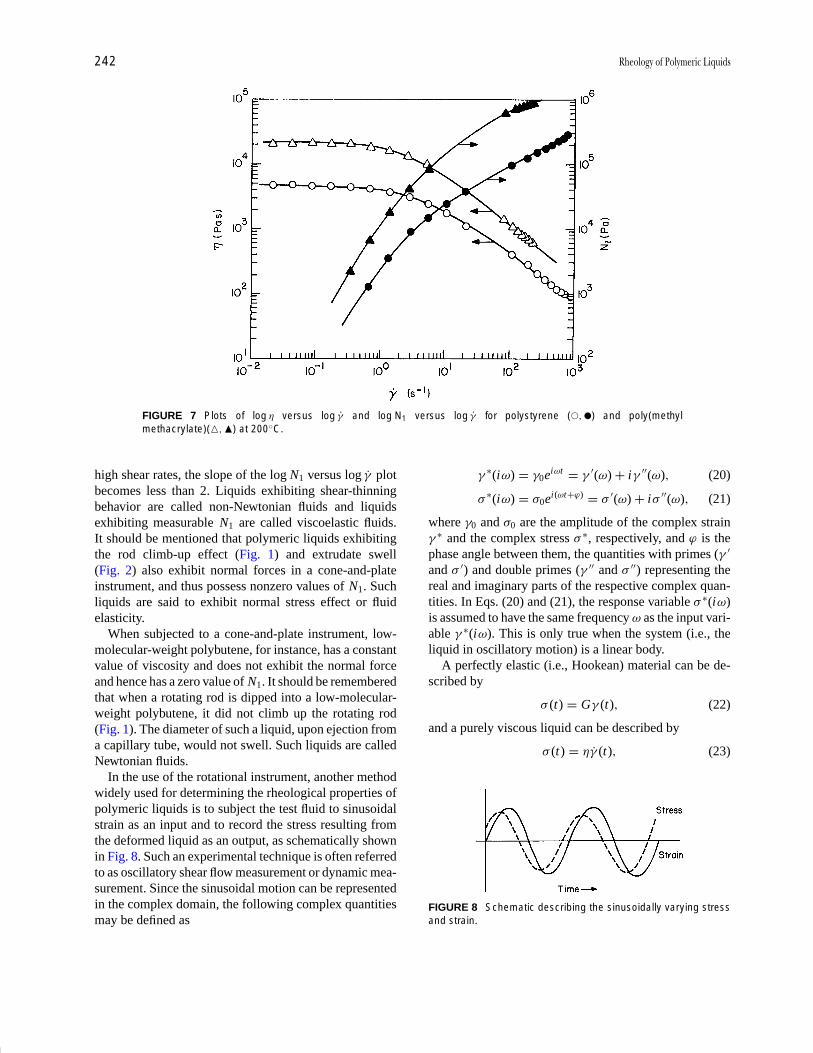
P1: GQT/MBQ P2: GPJ Final Pages
Encyclopedia of Physical Science and Technology EN014C-660 July 28, 2001 17:14
242 Rheology of Polymeric Liquids
FIGURE 7 Plots of log η versus log γ and log N1 versus log γ for polystyrene (�, �) and poly(methylmethacrylate)(�,�) at 200◦C.
high shear rates, the slope of the log N1 versus log γ plotbecomes less than 2. Liquids exhibiting shear-thinningbehavior are called non-Newtonian fluids and liquidsexhibiting measurable N1 are called viscoelastic fluids.It should be mentioned that polymeric liquids exhibitingthe rod climb-up effect (Fig. 1) and extrudate swell(Fig. 2) also exhibit normal forces in a cone-and-plateinstrument, and thus possess nonzero values of N1. Suchliquids are said to exhibit normal stress effect or fluidelasticity.
When subjected to a cone-and-plate instrument, low-molecular-weight polybutene, for instance, has a constantvalue of viscosity and does not exhibit the normal forceand hence has a zero value of N1. It should be rememberedthat when a rotating rod is dipped into a low-molecular-weight polybutene, it did not climb up the rotating rod(Fig. 1). The diameter of such a liquid, upon ejection froma capillary tube, would not swell. Such liquids are calledNewtonian fluids.
In the use of the rotational instrument, another methodwidely used for determining the rheological properties ofpolymeric liquids is to subject the test fluid to sinusoidalstrain as an input and to record the stress resulting fromthe deformed liquid as an output, as schematically shownin Fig. 8. Such an experimental technique is often referredto as oscillatory shear flow measurement or dynamic mea-surement. Since the sinusoidal motion can be representedin the complex domain, the following complex quantitiesmay be defined as
γ ∗(iω) = γ0eiωt = γ ′(ω) + iγ ′′(ω), (20)
σ ∗(iω) = σ0ei(ωt+ϕ) = σ ′(ω) + iσ ′′(ω), (21)
where γ0 and σ0 are the amplitude of the complex strainγ ∗ and the complex stress σ ∗, respectively, and ϕ is thephase angle between them, the quantities with primes (γ ′
and σ ′) and double primes (γ ′′ and σ ′′) representing thereal and imaginary parts of the respective complex quan-tities. In Eqs. (20) and (21), the response variable σ ∗(iω)is assumed to have the same frequency ω as the input vari-able γ ∗(iω). This is only true when the system (i.e., theliquid in oscillatory motion) is a linear body.
A perfectly elastic (i.e., Hookean) material can be de-scribed by
σ (t) = Gγ (t), (22)
and a purely viscous liquid can be described by
σ (t) = ηγ (t), (23)
FIGURE 8 Schematic describing the sinusoidally varying stressand strain.
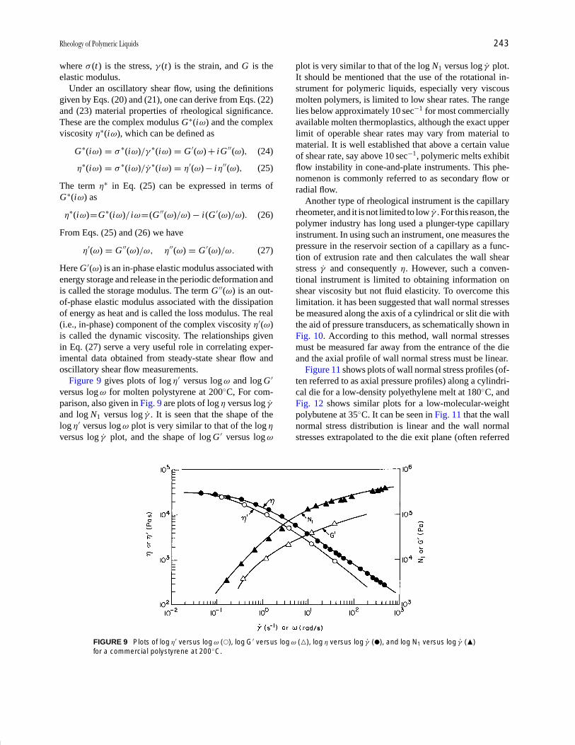
P1: GQT/MBQ P2: GPJ Final Pages
Encyclopedia of Physical Science and Technology EN014C-660 July 28, 2001 17:14
Rheology of Polymeric Liquids 243
where σ (t) is the stress, γ (t) is the strain, and G is theelastic modulus.
Under an oscillatory shear flow, using the definitionsgiven by Eqs. (20) and (21), one can derive from Eqs. (22)and (23) material properties of rheological significance.These are the complex modulus G∗(iω) and the complexviscosity η∗(iω), which can be defined as
G∗(iω) = σ ∗(iω)/γ ∗(iω) = G ′(ω) + iG ′′(ω), (24)
η∗(iω) = σ ∗(iω)/γ ∗(iω) = η′(ω) − iη′′(ω), (25)
The term η∗ in Eq. (25) can be expressed in terms ofG∗(iω) as
η∗(iω)=G∗(iω)/ iω=(G ′′(ω)/ω) − i(G ′(ω)/ω). (26)
From Eqs. (25) and (26) we have
η′(ω) = G ′′(ω)/ω, η′′(ω) = G ′(ω)/ω. (27)
Here G ′(ω) is an in-phase elastic modulus associated withenergy storage and release in the periodic deformation andis called the storage modulus. The term G ′′(ω) is an out-of-phase elastic modulus associated with the dissipationof energy as heat and is called the loss modulus. The real(i.e., in-phase) component of the complex viscosity η′(ω)is called the dynamic viscosity. The relationships givenin Eq. (27) serve a very useful role in correlating exper-imental data obtained from steady-state shear flow andoscillatory shear flow measurements.
Figure 9 gives plots of log η′ versus log ω and log G ′
versus log ω for molten polystyrene at 200◦C, For com-parison, also given in Fig. 9 are plots of log η versus log γand log N1 versus log γ . It is seen that the shape of thelog η′ versus log ω plot is very similar to that of the log η
versus log γ plot, and the shape of log G ′ versus log ω
FIGURE 9 Plots of log η′ versus log ω (�), log G′ versus log ω (�), log η versus log γ (�), and log N1 versus log γ (�)for a commercial polystyrene at 200◦C.
plot is very similar to that of the log N1 versus log γ plot.It should be mentioned that the use of the rotational in-strument for polymeric liquids, especially very viscousmolten polymers, is limited to low shear rates. The rangelies below approximately 10 sec−1 for most commerciallyavailable molten thermoplastics, although the exact upperlimit of operable shear rates may vary from material tomaterial. It is well established that above a certain valueof shear rate, say above 10 sec−1, polymeric melts exhibitflow instability in cone-and-plate instruments. This phe-nomenon is commonly referred to as secondary flow orradial flow.
Another type of rheological instrument is the capillaryrheometer, and it is not limited to low γ . For this reason, thepolymer industry has long used a plunger-type capillaryinstrument. In using such an instrument, one measures thepressure in the reservoir section of a capillary as a func-tion of extrusion rate and then calculates the wall shearstress γ and consequently η. However, such a conven-tional instrument is limited to obtaining information onshear viscosity but not fluid elasticity. To overcome thislimitation. it has been suggested that wall normal stressesbe measured along the axis of a cylindrical or slit die withthe aid of pressure transducers, as schematically shown inFig. 10. According to this method, wall normal stressesmust be measured far away from the entrance of the dieand the axial profile of wall normal stress must be linear.
Figure 11 shows plots of wall normal stress profiles (of-ten referred to as axial pressure profiles) along a cylindri-cal die for a low-density polyethylene melt at 180◦C, andFig. 12 shows similar plots for a low-molecular-weightpolybutene at 35◦C. It can be seen in Fig. 11 that the wallnormal stress distribution is linear and the wall normalstresses extrapolated to the die exit plane (often referred
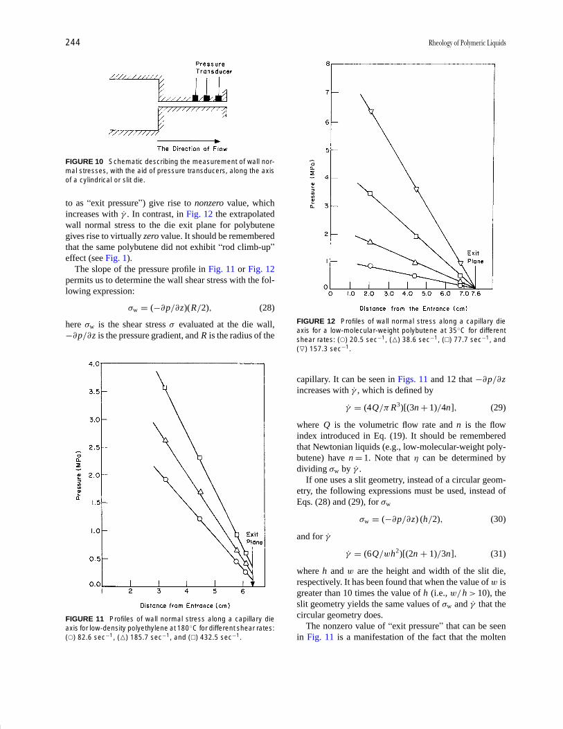
P1: GQT/MBQ P2: GPJ Final Pages
Encyclopedia of Physical Science and Technology EN014C-660 July 28, 2001 17:14
244 Rheology of Polymeric Liquids
FIGURE 10 Schematic describing the measurement of wall nor-mal stresses, with the aid of pressure transducers, along the axisof a cylindrical or slit die.
to as “exit pressure”) give rise to nonzero value, whichincreases with γ . In contrast, in Fig. 12 the extrapolatedwall normal stress to the die exit plane for polybutenegives rise to virtually zero value. It should be rememberedthat the same polybutene did not exhibit “rod climb-up”effect (see Fig. 1).
The slope of the pressure profile in Fig. 11 or Fig. 12permits us to determine the wall shear stress with the fol-lowing expression:
σw = (−∂p/∂z)(R/2), (28)
here σw is the shear stress σ evaluated at the die wall,−∂p/∂z is the pressure gradient, and R is the radius of the
FIGURE 11 Profiles of wall normal stress along a capillary dieaxis for low-density polyethylene at 180◦C for different shear rates:(�) 82.6 sec−1, (�) 185.7 sec−1, and (�) 432.5 sec−1.
FIGURE 12 Profiles of wall normal stress along a capillary dieaxis for a low-molecular-weight polybutene at 35◦C for differentshear rates: (�) 20.5 sec−1, (�) 38.6 sec−1, (�) 77.7 sec−1, and(�) 157.3 sec−1.
capillary. It can be seen in Figs. 11 and 12 that −∂p /∂zincreases with γ , which is defined by
γ = (4Q/π R3)[(3n + 1)/4n], (29)
where Q is the volumetric flow rate and n is the flowindex introduced in Eq. (19). It should be rememberedthat Newtonian liquids (e.g., low-molecular-weight poly-butene) have n = 1. Note that η can be determined bydividing σw by γ .
If one uses a slit geometry, instead of a circular geom-etry, the following expressions must be used, instead ofEqs. (28) and (29), for σw
σw = (−∂p/∂z) (h/2), (30)
and for γ
γ = (6Q/wh2)[(2n + 1)/3n], (31)
where h and w are the height and width of the slit die,respectively. It has been found that when the value of w isgreater than 10 times the value of h (i.e., w/h > 10), theslit geometry yields the same values of σw and γ that thecircular geometry does.
The nonzero value of “exit pressure” that can be seenin Fig. 11 is a manifestation of the fact that the molten
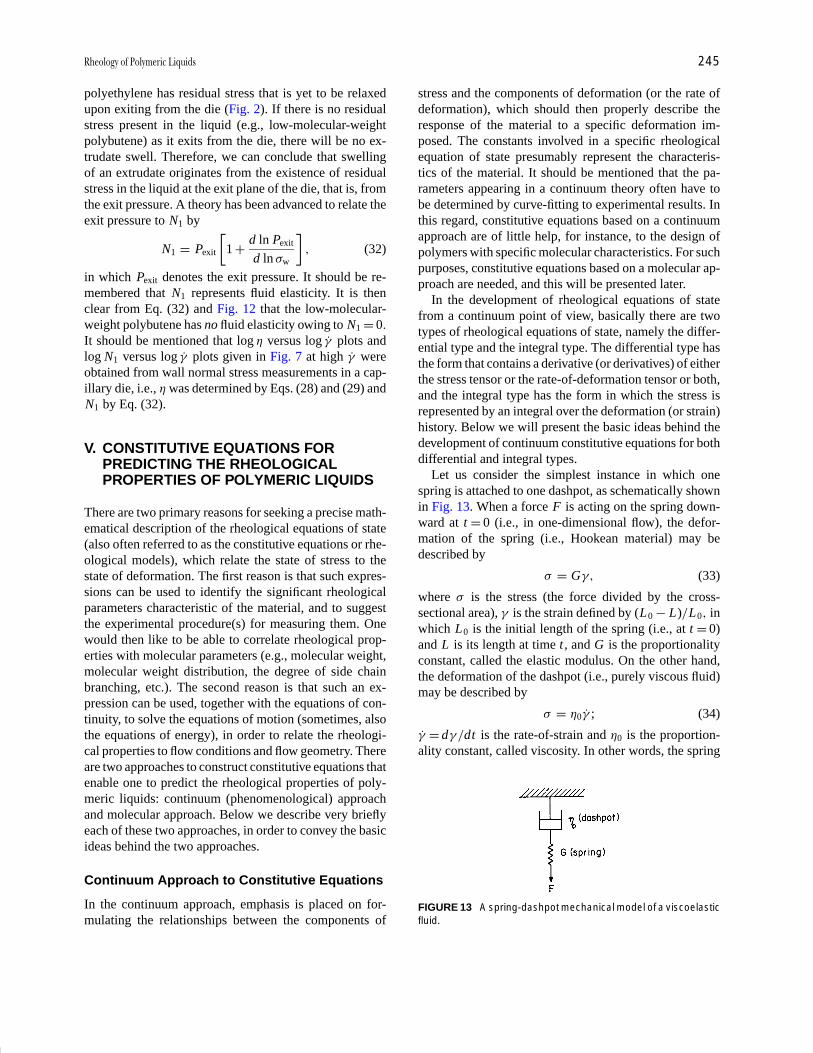
P1: GQT/MBQ P2: GPJ Final Pages
Encyclopedia of Physical Science and Technology EN014C-660 July 28, 2001 17:14
Rheology of Polymeric Liquids 245
polyethylene has residual stress that is yet to be relaxedupon exiting from the die (Fig. 2). If there is no residualstress present in the liquid (e.g., low-molecular-weightpolybutene) as it exits from the die, there will be no ex-trudate swell. Therefore, we can conclude that swellingof an extrudate originates from the existence of residualstress in the liquid at the exit plane of the die, that is, fromthe exit pressure. A theory has been advanced to relate theexit pressure to N1 by
N1 = Pexit
[1 + d ln Pexit
d ln σw
], (32)
in which Pexit denotes the exit pressure. It should be re-membered that N1 represents fluid elasticity. It is thenclear from Eq. (32) and Fig. 12 that the low-molecular-weight polybutene has no fluid elasticity owing to N1 = 0.
It should be mentioned that log η versus log γ plots andlog N1 versus log γ plots given in Fig. 7 at high γ wereobtained from wall normal stress measurements in a cap-illary die, i.e., η was determined by Eqs. (28) and (29) andN1 by Eq. (32).
V. CONSTITUTIVE EQUATIONS FORPREDICTING THE RHEOLOGICALPROPERTIES OF POLYMERIC LIQUIDS
There are two primary reasons for seeking a precise math-ematical description of the rheological equations of state(also often referred to as the constitutive equations or rhe-ological models), which relate the state of stress to thestate of deformation. The first reason is that such expres-sions can be used to identify the significant rheologicalparameters characteristic of the material, and to suggestthe experimental procedure(s) for measuring them. Onewould then like to be able to correlate rheological prop-erties with molecular parameters (e.g., molecular weight,molecular weight distribution, the degree of side chainbranching, etc.). The second reason is that such an ex-pression can be used, together with the equations of con-tinuity, to solve the equations of motion (sometimes, alsothe equations of energy), in order to relate the rheologi-cal properties to flow conditions and flow geometry. Thereare two approaches to construct constitutive equations thatenable one to predict the rheological properties of poly-meric liquids: continuum (phenomenological) approachand molecular approach. Below we describe very brieflyeach of these two approaches, in order to convey the basicideas behind the two approaches.
Continuum Approach to Constitutive Equations
In the continuum approach, emphasis is placed on for-mulating the relationships between the components of
stress and the components of deformation (or the rate ofdeformation), which should then properly describe theresponse of the material to a specific deformation im-posed. The constants involved in a specific rheologicalequation of state presumably represent the characteris-tics of the material. It should be mentioned that the pa-rameters appearing in a continuum theory often have tobe determined by curve-fitting to experimental results. Inthis regard, constitutive equations based on a continuumapproach are of little help, for instance, to the design ofpolymers with specific molecular characteristics. For suchpurposes, constitutive equations based on a molecular ap-proach are needed, and this will be presented later.
In the development of rheological equations of statefrom a continuum point of view, basically there are twotypes of rheological equations of state, namely the differ-ential type and the integral type. The differential type hasthe form that contains a derivative (or derivatives) of eitherthe stress tensor or the rate-of-deformation tensor or both,and the integral type has the form in which the stress isrepresented by an integral over the deformation (or strain)history. Below we will present the basic ideas behind thedevelopment of continuum constitutive equations for bothdifferential and integral types.
Let us consider the simplest instance in which onespring is attached to one dashpot, as schematically shownin Fig. 13. When a force F is acting on the spring down-ward at t = 0 (i.e., in one-dimensional flow), the defor-mation of the spring (i.e., Hookean material) may bedescribed by
σ = Gγ, (33)
where σ is the stress (the force divided by the cross-sectional area), γ is the strain defined by (L0 − L)/L0, inwhich L0 is the initial length of the spring (i.e., at t = 0)and L is its length at time t , and G is the proportionalityconstant, called the elastic modulus. On the other hand,the deformation of the dashpot (i.e., purely viscous fluid)may be described by
σ = η0γ ; (34)
γ = dγ /dt is the rate-of-strain and η0 is the proportion-ality constant, called viscosity. In other words, the spring
FIGURE 13 A spring-dashpot mechanical model of a viscoelasticfluid.

P1: GQT/MBQ P2: GPJ Final Pages
Encyclopedia of Physical Science and Technology EN014C-660 July 28, 2001 17:14
246 Rheology of Polymeric Liquids
exhibits purely an elastic effect (i.e., as a Hookean solid)and the dashpot exhibits purely a viscous effect (i.e., as aNewtonian fluid).
Therefore, the total strain of the “spring and dashpot” atany time t is the sum of that due to the spring (reversible)and that due to the dashpot (irreversible). CombiningEqs. (33) and (34), we obtain
σ + λ1dσ
dt= η0γ (35)
which is known as the one-dimensional Maxwell mechan-ical model. Note that λ1 = η0/G in Eq. (35) is a time con-stant, often referred to as the relaxation time. Equation (35)is capable of qualitatively explaining many well-knownviscoelastic phenomena, such as stress relaxation follow-ing a sudden change in deformation and elastic recoveryfollowing a sudden release of imposed stress.
If the partial derivative ∂/∂t , appearing in Eq. (35), isreplaced with the convected derivative ∂/∂t , we obtain
σ + λ1∂σ
∂t= η0d. (36)
This model predicts η = η0 and N1 = 2λ1γ2 for steady-
state shear flow. There are many different types of non-linear rheological models suggested in the literature. Oneof the simplest modifications that can be introduced intoEq. (36), in order to empirically correct the inherent de-fects that the linear Maxwell model has in predictingthe rheological properties of viscoelastic fluids, would beto make the material constants become shear dependent.There have been several attempts made to accomplish this,and one such generalization can made as
σ + λ(II)∂σ
∂t= 2η(II)d, (37)
where II represents the second invariant of the rate-of-deformation tensor d. For steady-state shear flow, the twoparameters λ(II) and η(II) may be expressed by
η(γ ) = η0[1 + (η1γ )2
](1−n)/2 , (38)
λ(γ ) = λ0[1 + (λ1γ )2
](1−m)/2 . (39)
There are many other differential-type constitutive equa-tions that can be found in the literature.
For infinitesimally small deformations, the integrationof Eq. (35) gives
σ (t) = 2∫ t
−∞
η0
λ1e−(t−t ′)/λ1 d(t ′) dt ′. (40)
Since polymeric materials consist of many segments ofdifferent submolecules, the properties of a polymeric ma-terial may be thought of being given in terms of a spectrum
of these variables (e.g., λi and ηi for the i th submolecule).If one assumes that the components of a stress are linearlyrelated to the components of the rate of deformation, thenthe overall response of the N submolecules may be ex-pressed by
σ (t) = 2∫ t
−∞
N∑i=1
η0
λie−(t−t ′)/λi d(t ′) dt ′. (41)
If one considers the rate of deformation as the cause and thestress as the resulting effect, then the observed “resultingeffect” at the present time is due to the sequence of causesup to the present time t from the remote past.
For large deformations, one can still write differential-type rheological equations of state with integral represen-tation, using appropriate transformations of the coordinatesystems involved, as
σ (t) = 2∫ t
−∞m(t − t ′)�(t, t ′) dt ′, (42)
where m(t − t ′) is referred to as the memory function and�(t, t ′) is the rate-of-deformation tensor in a coordinatesystem rotating with a fluid element. The memory functionm(t − t ′) for Eq. (40) is given by
m(t − t ′) = η0
λ1e−(t−t ′)/λ1 . (43)
One can derive expressions for three material functions,σ , N1, and N2, from Eq. (37), Eq. (40), or Eq. (42). Suchexpressions are well documented in the literature.
Molecular Approach to Constitutive Equations
The molecular approach is to relate the rheological be-havior of polymeric liquids to their molecular parameters,such as molecular weight, molecular weight distribution,and the extent of side chain branching. It is not difficultto surmise that the rheological properties of polymers aregreatly influenced by the molecular parameters. The pre-dictions of the rheological properties of polymers on thebasis of phenomenological theory is of little help eitherto control the quality of polymers produced or to improvethe performance of polymers, unless the parameters ap-pearing in various continuum constitutive equations arerelated to molecular parameters.
It is well established that the zero-shear viscosity (η0)of polymer is proportional to the molecular weight (M)below a critical value Mc, whereas above Mc it increasesrapidly and becomes proportional to M3.4, i.e.,
η0 ={
K M, for M ≤ Mc,
K M3.4, for M > Mc.(44)
The critical molecular weight Mc is believed to correspondto a value beyond which molecular entanglements (i.e.,
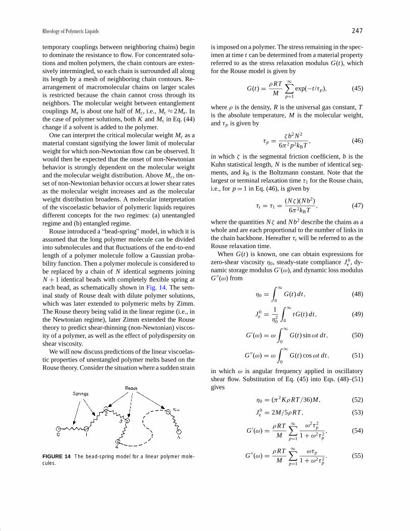
P1: GQT/MBQ P2: GPJ Final Pages
Encyclopedia of Physical Science and Technology EN014C-660 July 28, 2001 17:14
Rheology of Polymeric Liquids 247
temporary couplings between neighboring chains) beginto dominate the resistance to flow. For concentrated solu-tions and molten polymers, the chain contours are exten-sively intermingled, so each chain is surrounded all alongits length by a mesh of neighboring chain contours. Re-arrangement of macromolecular chains on larger scalesis restricted because the chain cannot cross through itsneighbors. The molecular weight between entanglementcouplings Me is about one half of Mc, i.e., Mc ≈ 2Me. Inthe case of polymer solutions, both K and Mc in Eq. (44)change if a solvent is added to the polymer.
One can interpret the critical molecular weight Mc as amaterial constant signifying the lower limit of molecularweight for which non-Newtonian flow can be observed. Itwould then be expected that the onset of non-Newtonianbehavior is strongly dependent on the molecular weightand the molecular weight distribution. Above Mc, the on-set of non-Newtonian behavior occurs at lower shear ratesas the molecular weight increases and as the molecularweight distribution broadens. A molecular interpretationof the viscoelastic behavior of polymeric liquids requiresdifferent concepts for the two regimes: (a) unentangledregime and (b) entangled regime.
Rouse introduced a “bead-spring” model, in which it isassumed that the long polymer molecule can be dividedinto submolecules and that fluctuations of the end-to-endlength of a polymer molecule follow a Gaussian proba-bility function. Then a polymer molecule is considered tobe replaced by a chain of N identical segments joiningN + 1 identical beads with completely flexible spring ateach bead, as schematically shown in Fig. 14. The sem-inal study of Rouse dealt with dilute polymer solutions,which was later extended to polymeric melts by Zimm.The Rouse theory being valid in the linear regime (i.e., inthe Newtonian regime), later Zimm extended the Rousetheory to predict shear-thinning (non-Newtonian) viscos-ity of a polymer, as well as the effect of polydispersity onshear viscosity.
We will now discuss predictions of the linear viscoelas-tic properties of unentangled polymer melts based on theRouse theory. Consider the situation where a sudden strain
FIGURE 14 The bead-spring model for a linear polymer mole-cules.
is imposed on a polymer. The stress remaining in the spec-imen at time t can be determined from a material propertyreferred to as the stress relaxation modulus G(t), whichfor the Rouse model is given by
G(t) = ρRT
M
∞∑p=1
exp(−t /τp), (45)
where ρ is the density, R is the universal gas constant, Tis the absolute temperature, M is the molecular weight,and τp is given by
τp = ζb2 N 2
6π2 p2kBT, (46)
in which ζ is the segmental friction coefficient, b is theKuhn statistical length, N is the number of identical seg-ments, and kB is the Boltzmann constant. Note that thelargest or terminal relaxation time τ1 for the Rouse chain,i.e., for p = 1 in Eq. (46), is given by
τr = τ1 = (Nζ )(Nb2)
6π2kBT, (47)
where the quantities Nζ and Nb2 describe the chains as awhole and are each proportional to the number of links inthe chain backbone. Hereafter τr will be referred to as theRouse relaxation time.
When G(t) is known, one can obtain expressions forzero-shear viscosity η0, steady-state compliance J 0
e , dy-namic storage modulus G ′(ω), and dynamic loss modulusG ′′(ω) from
η0 =∫ ∞
0G(t) dt, (48)
J 0e = 1
η20
∫ ∞
0tG(t) dt, (49)
G ′(ω) = ω
∫ ∞
0G(t) sin ωt dt, (50)
G ′′(ω) = ω
∫ ∞
0G(t) cos ωt dt, (51)
in which ω is angular frequency applied in oscillatoryshear flow. Substitution of Eq. (45) into Eqs. (48)–(51)gives
η0 = (π2 KρRT/36)M, (52)
J 0e = 2M/5ρRT, (53)
G ′(ω) = ρRT
M
∞∑p=1
ω2τ 2p
1 + ω2τ 2p
, (54)
G ′′(ω) = ρRT
M
∞∑p=1
ωτp
1 + ω2τ 2p
. (55)

P1: GQT/MBQ P2: GPJ Final Pages
Encyclopedia of Physical Science and Technology EN014C-660 July 28, 2001 17:14
248 Rheology of Polymeric Liquids
Note that K in Eq. (52) is defined by
K = ζb2 N 2
π2kBTM 2. (56)
The Rouse model allows us to determine that stress σ
contributed by the polymer chains by
σ =∞∑
p=2
σp, (57)
where σp denotes the stress contributed by the polymerchain at the pth mode (p = 1, 2, . . . ,∞), which can beevaluated from (
1 + τp∂
∂t
)σp = G0δ, (58)
where ∂/∂t is the upper convected derivative, τp is therelaxation times defined by Eq. (46), G0 = ρRT/M , andδ is the Kronecker delta function.
In steady-state shear flow the Rouse model predicts
σ = ρRT
M
∞∑p=1
τpγ , (59)
N1 = 2ρRT
M
∞∑p=1
τ 2p γ
2, (60)
N2 = 0. (61)
Use of Eq. (46) in Eq. (59) gives the zero-shear viscosity,
η0 = ρb2ζ NA N 2
36M, (62)
where NA is Avogadro’s number. Since N ∝ M , it can beconcluded from Eq. (62) that η0 ∝ M and it is independentof shear rate γ , i.e., the Rouse model cannot predict shear-dependent viscosity. Equation (62) can be rewritten as
η0 =(
ρb20ζ0 NA
36M20
)M, (63)
where b0 is the length of monomer, ζ0 is the monomericfriction coefficient, and M0 is the molecular weight ofmonomer. The ζ0 is one of the most important propertiesof macromolecules, which can be calculated from Eq. (63)by measurement of η0. With the aid of Eq. (63), Eq. (46)can be rewritten as
τp = 6η0 M
π2 p2ρRT, (64)
and thus the terminal (Rouse) relaxation time becomes
τr = τ1 = 6η0 M
π2ρRT. (65)
The Rouse model is useful to predict the linear vis-coelastic properties (Eqs. (52)–(55)) of polymer melts
FIGURE 15 Plots of log G′ versus log ω for a nearly monodis-perse polystyrene with molecular weight of 9 × 10³ at various tem-peratures: (�) 120◦C, (�) 130◦C, (�) 140◦C, and (�) 150◦C.
with molecular weight M less than Mc. Figure 15 givesplots of log G ′ versus log ω, and Fig. 16 gives plots oflog G ′′ versus log ω, measured at four different temper-atures for a monodisperse polystyrene with M = 9000,which is much lower than the Mc = 36,000 of polystyrene.It can be seen in these figures that (a) at a constant value
FIGURE 16 Plots of lot G′′ versus log ω for a nearly monodis-perse polystyrene with molecular weight of 9 × 10³ at various tem-peratures: (�) 120◦C, (�) 130◦C, (�) 140◦C, and (�) 150◦C.
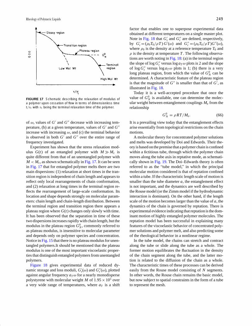
P1: GQT/MBQ P2: GPJ Final Pages
Encyclopedia of Physical Science and Technology EN014C-660 July 28, 2001 17:14
Rheology of Polymeric Liquids 249
FIGURE 17 Schematic describing the relaxation of modulus ofa polymer upon cessation of flow in terms of dimensionless timet/τ1 with τ1 being the terminal relaxation time of the polymer.
of ω, values of G ′ and G ′′ decrease with increasing tem-perature, (b) at a given temperature, values of G ′ and G ′′
increase with increasing ω, and (c) the terminal behavioris observed in both G ′ and G ′′ over the entire range offrequency investigated.
Experiment has shown that the stress relaxation mod-ulus G(t) of an entangled polymer with M � Mc isquite different from that of an unentangled polymer withM < Mc, as shown schematically in Fig. 17. It can be seenin Fig. 17 that for entangled polymer melts there are twomain dispersions: (1) relaxation at short times in the tran-sition region is independent of chain length and appears toreflect only local rearrangements of chain conformation,and (2) relaxation at long times in the terminal region re-flects the rearrangement of large-scale conformation. Itslocation and shape depends strongly on molecular param-eters: chain length and chain-length distribution. Betweenthe terminal region and transition region there appears aplateau region where G(t) changes only slowly with time.It has been observed that the separation in time of thesetwo dispersions increases rapidly with chain length, but themodulus in the plateau region G0
N , commonly referred toas plateau modulus, is insensitive to molecular parameterand depends only on polymer species and concentration.Notice in Fig. 15 that there is no plateau modulus for unen-tangled polymers.It should be mentioned that the plateaumodulus is one of the most important viscoelastic proper-ties that distinguish entangled polymers from unentangledpolymers.
Figure 18 gives experimental data of reduced dy-namic storage and loss moduli, G ′
r(ω) and G ′′r (ω), plotted
against angular frequency aT ω for a nearly monodispersepolystyrene with molecular weight M of 1.95 × 10⁵ overa very wide range of temperatures, where aT is a shift
factor that enables one to superpose experimental dataobtained at different temperatures on a single master plot.Note in Fig. 18 that G ′r and G ′′
r are defined, respectively,by G ′
r = (ρ0T0/ρT ) G ′(ω) and G ′′r = (ρ0T0/ρT )G ′′(ω),
where ρ0 is the density at a reference temperature T0 andρ is the density at temperature T . The following observa-tions are worth noting in Fig. 18: (a) in the terminal regionthe slope of log G ′′
r versus log aT ω plots is 2 and the slopeof log G ′′
r versus log aT ω plots is 1; (b) there is a verylong plateau region, from which the value of G0
N can bedetermined. A characteristic feature of the plateau regionis that the magnitude of G ′′ is smaller than that of G ′, asillustrated in Fig. 18.
Today it is a well-accepted procedure that once thevalue of G0
N is available, one can determine the molec-ular weight between entanglement couplings Me from therelationship
G0N = ρRT/Me. (66)
It is a prevailing view today that the entanglement effectsarise essentially from topological restrictions on the chainmotions.
A molecular theory for concentrated polymer solutionsand melts was developed by Doi and Edwards. Their the-ory is based on the premise that a polymer chain is confinedwithin a fictitious tube, through which the polymer chainmoves along the tube axis in reptative mode, as schemati-cally shown in Fig. 19. The Doi–Edwards theory is oftenreferred to as the “tube model,” in which the principalmolecular motion considered is that of reptation confinedwithin a tube. If the characteristic length scale of motion issmaller than the tube diameter a, the entanglement effectis not important, and the dynamics are well described bythe Rouse model (or the Zimm model if the hydrodynamicinteraction is dominant). On the other hand, if the lengthscale of the motion becomes larger than the value of a, thedynamics of the chain is governed by reptation. There isexperimental evidence indicating that reptation is the dom-inant motion of highly entangled polymer molecules. Thereptation model has been successful in explaining manyfeatures of the viscoelastic behavior of concentrated poly-mer solutions and polymer melt, and also predicting someof the rheological behavior in a nonlinear regime.
In the tube model, the chains can stretch and contractalong the tube or slide along the tube as a whole. Theformer motion equilibrates the fluctuation in the densityof the chain segment along the tube, and the latter mo-tion is related to the diffusion of the chain as a whole.The characteristic times of these processes can be derivedeasily from the Rouse model consisting of N segments.In other words, the Rouse chain remains the basic model,but now subject to spatial constraints in the form of a tubeto represent the mesh.
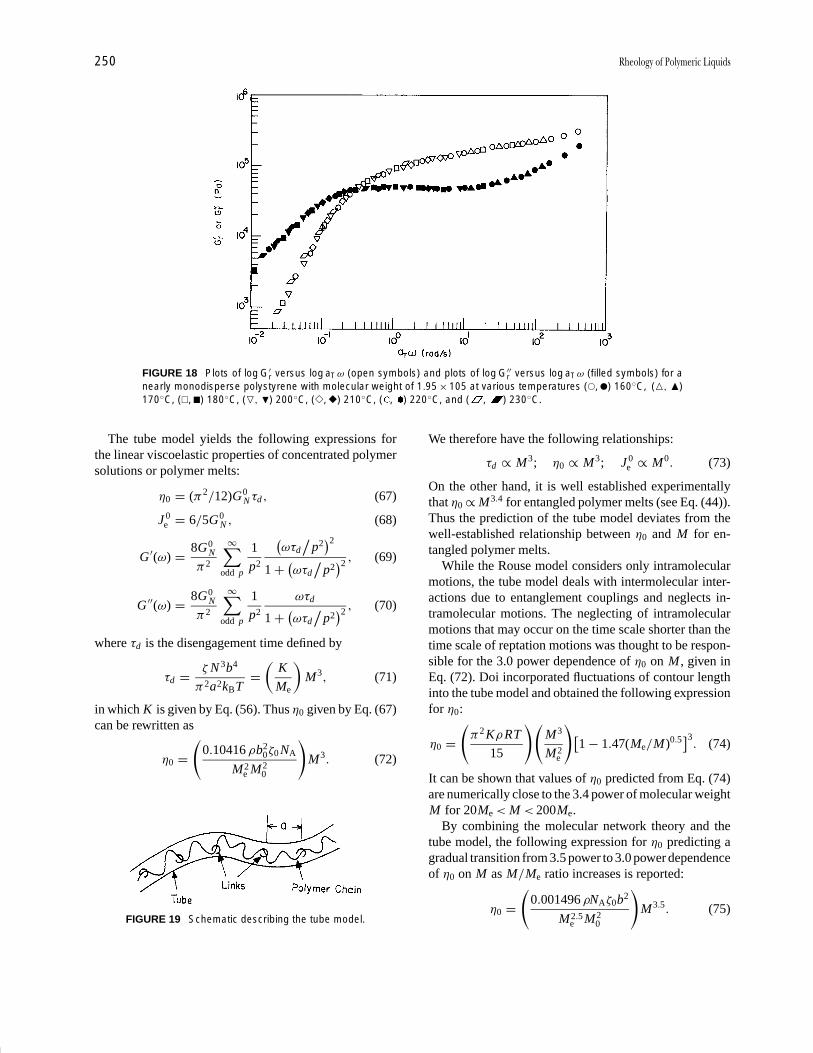
P1: GQT/MBQ P2: GPJ Final Pages
Encyclopedia of Physical Science and Technology EN014C-660 July 28, 2001 17:14
250 Rheology of Polymeric Liquids
FIGURE 18 Plots of log G′r versus log aTω (open symbols) and plots of log G′′
r versus log aTω (filled symbols) for anearly monodisperse polystyrene with molecular weight of 1.95 × 10⁵ at various temperatures (�, �) 160◦C, (�, �)170◦C, (�, �) 180◦C, (�, �) 200◦C, (�, �) 210◦C, ( , ) 220◦C, and ( , ) 230◦C.
The tube model yields the following expressions forthe linear viscoelastic properties of concentrated polymersolutions or polymer melts:
η0 = (π2/12)G0N τd , (67)
J 0e = 6/5G0
N , (68)
G ′(ω) = 8G0N
π2
∞∑odd p
1
p2
(ωτd
/p2
)2
1 + (ωτd
/p2
)2 , (69)
G ′′(ω) = 8G0N
π2
∞∑odd p
1
p2
ωτd
1 + (ωτd
/p2
)2 , (70)
where τd is the disengagement time defined by
τd = ζ N 3b4
π2a2kBT=
(K
Me
)M3, (71)
in which K is given by Eq. (56). Thus η0 given by Eq. (67)can be rewritten as
η0 =(
0.10416 ρb20ζ0 NA
M2e M2
0
)M3. (72)
FIGURE 19 Schematic describing the tube model.
We therefore have the following relationships:
τd ∝ M3; η0 ∝ M3; J 0e ∝ M0. (73)
On the other hand, it is well established experimentallythat η0 ∝ M3.4 for entangled polymer melts (see Eq. (44)).Thus the prediction of the tube model deviates from thewell-established relationship between η0 and M for en-tangled polymer melts.
While the Rouse model considers only intramolecularmotions, the tube model deals with intermolecular inter-actions due to entanglement couplings and neglects in-tramolecular motions. The neglecting of intramolecularmotions that may occur on the time scale shorter than thetime scale of reptation motions was thought to be respon-sible for the 3.0 power dependence of η0 on M , given inEq. (72). Doi incorporated fluctuations of contour lengthinto the tube model and obtained the following expressionfor η0:
η0 =(
π2 KρRT
15
)(M3
M2e
)[1 − 1.47(Me/M)0.5
]3. (74)
It can be shown that values of η0 predicted from Eq. (74)are numerically close to the 3.4 power of molecular weightM for 20Me < M < 200Me.
By combining the molecular network theory and thetube model, the following expression for η0 predicting agradual transition from 3.5 power to 3.0 power dependenceof η0 on M as M/Me ratio increases is reported:
η0 =(
0.001496 ρNAζ0b2
M2.5e M2
0
)M3.5. (75)
P1: GQT/MBQ P2: GPJ Final Pages
Encyclopedia of Physical Science and Technology EN014C-660 July 28, 2001 17:14
Rheology of Polymeric Liquids 251
It should be pointed out that Eq. (75) was derived with-out invoking fluctuations of contour length (i.e., withoutconsidering the Rouse motion in a reptating chain). Themain idea behind the derivation of Eq. (75) is that sinceexperimental data for η0 is usually obtained from shearmeasurement, stress effect must be included into the rep-tation model; i.e., when a polymer is subjected to shearflow, a relaxation of polymer chains to reptate around theentangled junctions must be taken into consideration, inaddition to the reptation of the overall center-of-mass mo-tion. For very high-molecular-weight polymers, the ap-proach used to derive Eq. (75) yields
η0 =(
0.02916ρζ0b20 NA
M2e M2
0
)M3. (76)
It has been shown that the combination of Eqs. (75) and(76) predicts a gradual transition from a 3.4 power law toa 3.0 power law for 200Me < M < 2000Me, which com-pares very favorably with experiment.
The tube model predicts, for steady-state shear flow,three material functions, η, N1, and N2, and they are ex-pressed by
η = (G0/γ )∫ ∞
0m(s)F1(γ s) ds, (77)
N1 = G0γ
∫ ∞
0sm(s)F1(γ s) ds, (78)
N2 = −G0
∫ ∞
0m(s)F2(γ s) ds, (79)
where γ denotes shear rate, m(s) is a memory function,and F1(γ s) and F2(γ s) are complicated expressions notshown here.
VI. CONCLUDING REMARKS
In studying the rheology of a specific type of material,one needs to perform the following three basic steps: (1)define the flow field in terms of the velocity componentsand the coordinates that are most appropriate; (2) choosea rheological equation of state for the description of thematerial under deformation, and (3) decide which of theexperimental techniques available are most suitable for de-termining the rheological properties of the material underconsideration.
There are two reasons for seeking a precise mathemat-ical description of the rheological models, which relatethe state of stress to the state of deformation. The first isthat such an expression can be used to identify the signifi-cant rheological parameters characteristic of the materialsand to suggest the experimental procedure for measuringthem. One would then like to correlate the rheological
parameters with the molecular weight, molecular weightdistribution, and molecular structure. The second reasonis that such an expression can be used, together with theequation of continuity, to solve the equations of motionthat relate the rheological parameters to flow conditionsand die geometry.
In the past, much effort has been put into developingrheological models for predicting the rheological prop-erties of polymeric liquids. There are two approaches todescribing the rheological behavior of viscoelastic poly-meric liquids. One approach is to view the material asa continuum, and then to describe the response of thiscontinuum to stress or strain by a system of mathematicalstatements having their origin in the theories of continuummechanics. Another approach is to describe the rheolog-ical behavior of the material from molecular considera-tions. In either approach, one basically has to establisha relationship (or relationships) on the basis of either arigorous mathematical physical theory or empiricism, orboth, which describes the deformation of a fluid in termsof the components of the deformation history or the rateof deformation and the components of the stress.
As an important application of rheology, one can citeprocessing of polymeric materials. The polymer process-ing industry constantly strives to improve its existing pro-cessing techniques and to develop new ones with the pur-pose of finding optimum processing conditions for eachnew material that comes on the market. Therefore, thedevelopment of a method or methods for evaluating theprocessibility of a new polymeric material and for im-proving existing processing conditions is an essential stepin improving the mechanical or other properties of thefinal product. On the basis of the information presentedhere, it can be concluded that proccesibility is very closelyrelated to the rheological properties of the polymeric ma-terials in the molten state and that a good understandingof any polymer processing operation requires knowledgeof several branches of science and engineering, such aspolymer chemistry, polymer physics, polymer rheology,and mass and energy transports.
SEE ALSO THE FOLLOWING ARTICLES
FLUID DYNAMICS (CHEMICAL ENGINEERING) • LIQUID
CRYSTALS •LIQUIDS, STRUCTURE AND DYNAMICS •PLAS-TICS ENGINEERING • POLYMER PROCESSING • POLYMERS,MECHANICAL BEHAVIOR • RUBBER, SYNTHETIC • STERE-OCHEMISTRY
BIBLIOGRAPHY
Bird, R. B., Armstrong, R. C., and Hassager, O. (1987). “Dynamics ofPolymeric Liquid,” 2nd edition, Vol. 1, Wiley, New York.

P1: GQT/MBQ P2: GPJ Final Pages
Encyclopedia of Physical Science and Technology EN014C-660 July 28, 2001 17:14
252 Rheology of Polymeric Liquids
Collyer, A. A., and Clegg. D. W., eds. (1998). “Rheological Measure-ment,” 2nd edition, Chapman & Hall, London.
Doi, M., and Edwards, S. F. (1986). “The Theory of Polymer Dynamics,”Clarendon Press, Oxford.
Ferry, J. D. (1980). “Viscoelastic Properties of Polymers,” 3rd editionWiley, New York.
Han, C. D. (1976). “Rheology in Polymer Processing,” Academic Press,New York.
Han, C. D. (1981). “Multiphase Flow in Polymer Processing,” AcademicPress, New York.
Han, C. D. (1998). In “Rheological Measurement,” A. A. Collyer andD. W. Clegg, eds., 2nd edition, pp. 190–209, Chapman & Hall,London.
Larson, R. D. (1988). “Constitutive Equations for Polymer Melts andSolutions,” Butterworth, Stoneham, MA.
Walters, K. (1975). “Rheometry,” Chapman & Hall, London.

P1: GQQ/GLT P2: GRB Final Pages Qu: 00, 00, 00, 00
Encyclopedia of Physical Science and Technology EN014B-670 July 28, 2001 16:50
Rubber, NaturalStephen T. SemegenSTS Technical Services
I. IntroductionII. AgricultureIII. PreparationIV. Modified Rubber and DerivativesV. Properties
VI. Product UsagesVII. Economics
VIII. Research
GLOSSARY
Crystallization, polymer Arrangement of previouslydisordered polymer segments of repeating patterns intogeometric symmetry.
Latex, rubber Colloidal aqueous dispersion of rubber.Monomer Low-molecular-weight substance consisting
of molecules capable of reacting to form a polymer.Polymer Three-dimensional substance of molecules
characterized by repetition of one or more monomerunits.
Rubber Material that is capable of recovering (retracting)quickly from large deformations.
Rubber product Item of commerce whose major portionconsists of rubber.
Rubber, raw Vulcanizable macromolecular material,used to produce a rubber product.
Tack, rubber Property causing contacting surfaces ofraw rubber to adhere to each other.
Transition, first order Reversible change in phase of amaterial, as in melting or crystalization of polymers.
Transition, glass Reversible change in a material from aviscous or rubbery state to a brittle glassy state.
Vulcanization Irreversible process changing the chemi-cal structure of a rubber (cross-linking), becoming lessplastic, more elastic, and extending the usable temper-ature range.
NATURAL RUBBER is a cis-1,4-polyisoprene obtainedfrom a botanical source and is the oldest known rubber. Itis also the most versatile one for fabrication into rubberproducts. Before World War II, natural rubber accountedfor practically 100% of all rubber usage. Two-thirds ofthis total usage is for tires. However, natural rubber didnot become an important industrial commodity until thediscovery of sulfur vulcanization in 1839 and the inventionof the pneumatic tire in 1888.
Even so, natural-rubber-containing trees originallygrew wild in the jungles of South America. They hadto be domesticated and raised as an agricultural cropon cultivated farms and plantations. Finally, a tapping
381
P1: GQQ/GLT P2: GRB Final Pages
Encyclopedia of Physical Science and Technology EN014B-670 July 28, 2001 16:50
382 Rubber, Natural
system had to be devised to remove the rubber latex fromthe tree without permanent damage to the tree. By 1900,the modern rubber industry had been born. Today, naturaland synthetic rubbers enjoy a symbiotic relationship.
I. INTRODUCTION
Natural rubber is a high-molecular-weight polymer ofisoprene, whose chemical structure is 2-methyl-1,3-butadiene. Natural rubber most commonly is obtainedfrom the latex of the Hevea brasiliensis tree. The Heveatree is indigenous to South America, especially in theAmazon valley. However, for the past hundred years, ithas been cultivated in many tropical areas around theworld. Principally, this species is grown in SoutheastAsia, especially Malaysia and Indonesia. As a rule,regions that are 5–10◦ latitude north or south of theequator can grow rubber trees. Heavy rainfall over thefull year, temperatures holding between 70 and 90◦F,and elevations preferably no higher than a thousand feetabove sea level are necessary for commercial growth.
More than 14 million acres, currently containing morethan 2 billion rubber trees, had to be cleared out of densejungles and rain forests in Southeast Asia. Conversely, theHevea brasiliensis tree is practically no longer cultivatedin its South American birthplace, because of its suscep-tibility to leaf blight disease. The latter is caused by afungus, Dothidella ulei. Some progress has been maderecently in controlling the disease, but not yet on a com-mercial scale. Two Hevea species are known that are re-sistant to the leaf blight—Hevea benthaniama and Heveapauciflora. Efforts have been made to cross-breed Heveabrasiliensis in order to develop high-yielding progeny andhigh-quality rubber.
Natural rubber is present in varying degree in at least200 different species of plants, including such commonweeds as goldenrod and dandelion (Table I). All thesespecies fall short of Hevea in yield, purity, frequency of
TABLE I Some Common Rubber-Bearing PlantSpecies
Name Habitat
Funtumia elastica Africa
Landolphia Africa
Castilloa elastica Mexico
Manihot glaziovii (Ceara) South America
Ficus elastica India, Burma
Taraxacum koksagys Russia
Parthenium argentatum Mexico, United States(Guayule) (California)
Cryptostegia grandiflora United States (Florida)
tapping, and longevity. All contain more resin, that is,acetone-soluble material. For example, the Russian dan-delion koksagys contains only 10% rubber hydrocarbon,gathered from the roots. Goldenrod is reputed to haveabout 8% rubber in its stems. During World War II, sev-eral of these species were utilized when the Asian sourceswere cut off. Guayule has recently been reactivated in ajoint program by Mexico and the United States. Its idealaim is freedom from dependency on overseas sources.In practical reality, it is a program by the U.S. Depart-ment of Agriculture and the U.S. Bureau of Indian Affairsto provide employment in Mexico and the southwesternUnited States.
A. Historical Background
Natural rubber has been traced back to the eleventh centurywhen the Mayan Indians made simple articles from it. Firstscientific observations were made by the French, Charlesde la Condamine and C. F. Fresneau. They identified therubber trees as the species Hevea Brasiliensis.
Economic growth of natural rubber was hampered byits thermoplastic behavior. In 1939, independent discoveryof vulcanization with sulfur was independently made inthe United States by Charles Goodyear and in England byThomas Hancock.
In 1888, the Englishman, John Dunlop developed thepneumatic tire, for bicycles. With the advent of the au-tomobile, the current rubber industry was born. However,natural rubber was native to only Central and South Amer-ica, where it was highly susceptible to yellow leaf blightdisease.
In 1876, Sir Henry Wickham gathered 70,000 Hevearubber seeds in Brazil. These were ultimately planted asseedlings throughout Southeast Asia. From these plants,75% of the total cultivated rubber in the world has sprung.
Plantation rubber became a reality in 1888. Henry N.Ridley, director of the Botanic Gardens in Singapore, dis-covered the current method of “tapping” a tree to obtainthe latex. He is known as the father of the modern planta-tion industry.
Within a decade, Indonesia, Sri Lanka, and Malayastarted rubber plantations. Ridley later showed that rub-ber trees could be planted in regular rows in clear areas,that trees could be tapped every few days, and that thetrees would produce latex efficiently for at least 30 years.Rapid growth of rubber production followed (Table II).
II. AGRICULTURE
A. Botanical Studies
The Hevea tree is a tall tree, averaging 60 ft in height,and reaching as high as 120 ft. The bark is smooth and
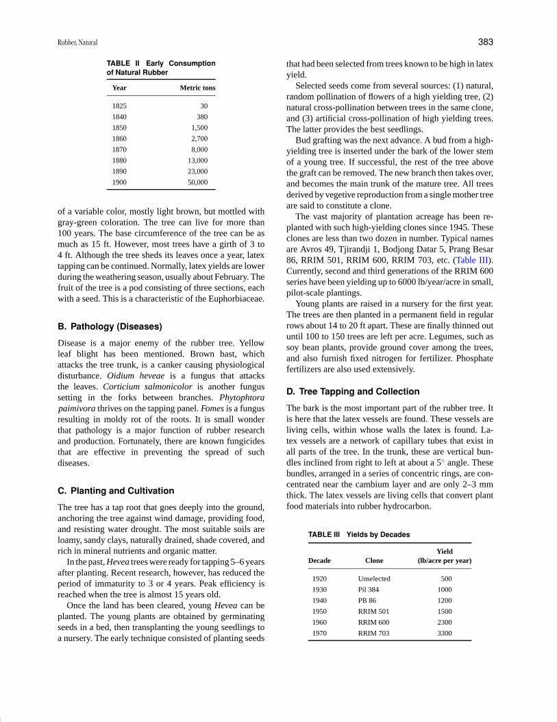
P1: GQQ/GLT P2: GRB Final Pages
Encyclopedia of Physical Science and Technology EN014B-670 July 28, 2001 16:50
Rubber, Natural 383
TABLE II Early Consumptionof Natural Rubber
Year Metric tons
1825 30
1840 380
1850 1,500
1860 2,700
1870 8,000
1880 13,000
1890 23,000
1900 50,000
of a variable color, mostly light brown, but mottled withgray-green coloration. The tree can live for more than100 years. The base circumference of the tree can be asmuch as 15 ft. However, most trees have a girth of 3 to4 ft. Although the tree sheds its leaves once a year, latextapping can be continued. Normally, latex yields are lowerduring the weathering season, usually about February. Thefruit of the tree is a pod consisting of three sections, eachwith a seed. This is a characteristic of the Euphorbiaceae.
B. Pathology (Diseases)
Disease is a major enemy of the rubber tree. Yellowleaf blight has been mentioned. Brown bast, whichattacks the tree trunk, is a canker causing physiologicaldisturbance. Oidium heveae is a fungus that attacksthe leaves. Corticium salmonicolor is another fungussetting in the forks between branches. Phytophtorapaimivora thrives on the tapping panel. Fomes is a fungusresulting in moldy rot of the roots. It is small wonderthat pathology is a major function of rubber researchand production. Fortunately, there are known fungicidesthat are effective in preventing the spread of suchdiseases.
C. Planting and Cultivation
The tree has a tap root that goes deeply into the ground,anchoring the tree against wind damage, providing food,and resisting water drought. The most suitable soils areloamy, sandy clays, naturally drained, shade covered, andrich in mineral nutrients and organic matter.
In the past, Hevea trees were ready for tapping 5–6 yearsafter planting. Recent research, however, has reduced theperiod of immaturity to 3 or 4 years. Peak efficiency isreached when the tree is almost 15 years old.
Once the land has been cleared, young Hevea can beplanted. The young plants are obtained by germinatingseeds in a bed, then transplanting the young seedlings toa nursery. The early technique consisted of planting seeds
that had been selected from trees known to be high in latexyield.
Selected seeds come from several sources: (1) natural,random pollination of flowers of a high yielding tree, (2)natural cross-pollination between trees in the same clone,and (3) artificial cross-pollination of high yielding trees.The latter provides the best seedlings.
Bud grafting was the next advance. A bud from a high-yielding tree is inserted under the bark of the lower stemof a young tree. If successful, the rest of the tree abovethe graft can be removed. The new branch then takes over,and becomes the main trunk of the mature tree. All treesderived by vegetive reproduction from a single mother treeare said to constitute a clone.
The vast majority of plantation acreage has been re-planted with such high-yielding clones since 1945. Theseclones are less than two dozen in number. Typical namesare Avros 49, Tjirandji 1, Bodjong Datar 5, Prang Besar86, RRIM 501, RRIM 600, RRIM 703, etc. (Table III).Currently, second and third generations of the RRIM 600series have been yielding up to 6000 lb/year/acre in small,pilot-scale plantings.
Young plants are raised in a nursery for the first year.The trees are then planted in a permanent field in regularrows about 14 to 20 ft apart. These are finally thinned outuntil 100 to 150 trees are left per acre. Legumes, such assoy bean plants, provide ground cover among the trees,and also furnish fixed nitrogen for fertilizer. Phosphatefertilizers are also used extensively.
D. Tree Tapping and Collection
The bark is the most important part of the rubber tree. Itis here that the latex vessels are found. These vessels areliving cells, within whose walls the latex is found. La-tex vessels are a network of capillary tubes that exist inall parts of the tree. In the trunk, these are vertical bun-dles inclined from right to left at about a 5◦ angle. Thesebundles, arranged in a series of concentric rings, are con-centrated near the cambium layer and are only 2–3 mmthick. The latex vessels are living cells that convert plantfood materials into rubber hydrocarbon.
TABLE III Yields by Decades
YieldDecade Clone (lb/acre per year)
1920 Unselected 500
1930 Pil 384 1000
1940 PB 86 1200
1950 RRIM 501 1500
1960 RRIM 600 2300
1970 RRIM 703 3300
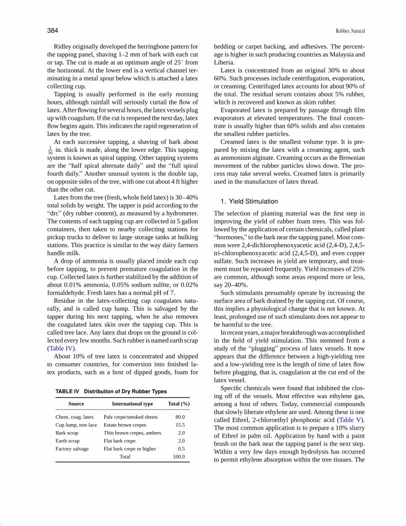
P1: GQQ/GLT P2: GRB Final Pages
Encyclopedia of Physical Science and Technology EN014B-670 July 28, 2001 16:50
384 Rubber, Natural
Ridley originally developed the herringbone pattern forthe tapping panel, shaving 1–2 mm of bark with each cutor tap. The cut is made at an optimum angle of 25◦ fromthe horizontal. At the lower end is a vertical channel ter-minating in a metal spout below which is attached a latexcollecting cup.
Tapping is usually performed in the early morninghours, although rainfall will seriously curtail the flow oflatex. After flowing for several hours, the latex vessels plugup with coagulum. If the cut is reopened the next day, latexflow begins again. This indicates the rapid regeneration oflatex by the tree.
At each successive tapping, a shaving of bark about1
16 in. thick is made, along the lower edge. This tappingsystem is known as spiral tapping. Other tapping systemsare the “half spiral alternate daily” and the “full spiralfourth daily.” Another unusual system is the double tap,on opposite sides of the tree, with one cut about 4 ft higherthan the other cut.
Latex from the tree (fresh, whole field latex) is 30–40%total solids by weight. The tapper is paid according to the“drc” (dry rubber content), as measured by a hydrometer.The contents of each tapping cup are collected in 5 galloncontainers, then taken to nearby collecting stations forpickup trucks to deliver to large storage tanks at bulkingstations. This practice is similar to the way dairy farmershandle milk.
A drop of ammonia is usually placed inside each cupbefore tapping, to prevent premature coagulation in thecup. Collected latex is further stabilized by the addition ofabout 0.01% ammonia, 0.05% sodium sulfite, or 0.02%formaldehyde. Fresh latex has a normal pH of 7.
Residue in the latex-collecting cup coagulates natu-rally, and is called cup lump. This is salvaged by thetapper during his next tapping, when he also removesthe coagulated latex skin over the tapping cup. This iscalled tree lace. Any latex that drops on the ground is col-lected every few months. Such rubber is named earth scrap(Table IV).
About 10% of tree latex is concentrated and shippedto consumer countries, for conversion into finished la-tex products, such as a host of dipped goods, foam for
TABLE IV Distribution of Dry Rubber Types
Source International type Total (%)
Chem. coag. latex Pale crepe/smoked sheets 80.0
Cup lump, tree lace Estate brown crepes 15.5
Bark scrap Thin brown crepes, ambers 2.0
Earth scrap Flat bark crepe 2.0
Factory salvage Flat bark crepe or higher 0.5
Total 100.0
bedding or carpet backing, and adhesives. The percent-age is higher in such producing countries as Malaysia andLiberia.
Latex is concentrated from an original 30% to about60%. Such processes include centrifugation, evaporation,or creaming. Centrifuged latex accounts for about 90% ofthe total. The residual serum contains about 5% rubber,which is recovered and known as skim rubber.
Evaporated latex is prepared by passage through filmevaporators at elevated temperatures. The final concen-trate is usually higher than 60% solids and also containsthe smallest rubber particles.
Creamed latex is the smallest volume type. It is pre-pared by mixing the latex with a creaming agent, suchas ammonium alginate. Creaming occurs as the Brownianmovement of the rubber particles slows down. The pro-cess may take several weeks. Creamed latex is primarilyused in the manufacture of latex thread.
1. Yield Stimulation
The selection of planting material was the first step inimproving the yield of rubber foam trees. This was fol-lowed by the application of certain chemicals, called plant“hormones,” to the bark near the tapping panel. Most com-mon were 2,4-dichlorophenoxyacetic acid (2,4-D), 2,4,5-tri-chlorophenoxyacetic acid (2,4,5-D), and even coppersulfate. Such increases in yield are temporary, and treat-ment must be repeated frequently. Yield increases of 25%are common, although some areas respond more or less,say 20–40%.
Such stimulants presumably operate by increasing thesurface area of bark drained by the tapping cut. Of course,this implies a physiological change that is not known. Atleast, prolonged use of such stimulants does not appear tobe harmful to the tree.
In recent years, a major breakthrough was accomplishedin the field of yield stimulation. This stemmed from astudy of the “plugging” process of latex vessels. It nowappears that the difference between a high-yielding treeand a low-yielding tree is the length of time of latex flowbefore plugging, that is, coagulation at the cut end of thelatex vessel.
Specific chemicals were found that inhibited the clos-ing off of the vessels. Most effective was ethylene gas,among a host of others. Today, commercial compoundsthat slowly liberate ethylene are used. Among these is onecalled Ethrel, 2-chloroethyl phosphonic acid (Table V).The most common application is to prepare a 10% slurryof Ethrel in palm oil. Application by hand with a paintbrush on the bark near the tapping panel is the next step.Within a very few days enough hydrolysis has occurredto permit ethylene absorption within the tree tissues. The
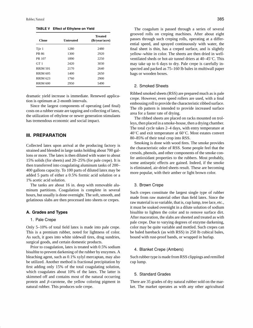
P1: GQQ/GLT P2: GRB Final Pages
Encyclopedia of Physical Science and Technology EN014B-670 July 28, 2001 16:50
Rubber, Natural 385
TABLE V Effect of Ethylene on Yield
TreatedClone Untreated (lb/year/acre)
Tjir 1 1280 2480
PB 86 1300 2920
PR 107 1890 2250
GT 1 2420 3030
RRIM 501 2170 2640
RRIM 605 1400 2650
RRIM 623 1760 2900
RRIM 600 2950 5490
dramatic yield increase is immediate. Renewed applica-tion is optimum at 2-month intervals.
Since the largest components of operating (and final)costs on a rubber estate are tapping and collecting of latex,the utilization of ethylene or newer generation stimulantshas tremendous economic and social impact.
III. PREPARATION
Collected latex upon arrival at the producing factory isstrained and blended in large tanks holding about 700 gal-lons or more. The latex is then diluted with water to about15% solids (for sheets) and 20–25% (for pale crepe). It isthen transferred into coagulating aluminum tanks of 200–400 gallons capacity. To 100 parts of diluted latex may beadded 5 parts of either a 0.5% formic acid solution or a1% acetic acid solution.
The tanks are about 16 in. deep with removable alu-minum partitions. Coagulation is complete in severalhours, but usually is done overnight. The soft, smooth, andgelatinous slabs are then processed into sheets or crepes.
A. Grades and Types
1. Pale Crepe
Only 5–10% of total field latex is made into pale crepe.This is a premium rubber, noted for lightness of color.As such, it goes into white sidewall tires, drug sundries,surgical goods, and certain domestic products.
Prior to coagulation, latex is treated with 0.5% sodiumbisulfite to prevent darkening of the rubber by enzymes. Ableaching agent, such as 0.1% xylyl mercaptan, may alsobe utilized. Another method is fractional precipitation byfirst adding only 15% of the total coagulating solution,which coagulates about 10% of the latex. The latter isskimmed off and contains most of the natural occurringprotein and β-carotene, the yellow coloring pigment innatural rubber. This produces sole crepe.
The coagulum is passed through a series of severalgrooved rolls on creping machines. After about eightpasses through such creping rolls, operating at a differ-ential speed, and sprayed continuously with water, thefinal sheet is thin, has a creped surface, and is slightlyyellow–white in color. The sheets are then dried in well-ventilated sheds or hot-air tunnel driers at 40–45◦C. Thismay take up to 6 days to dry. Pale crepe is carefully in-spected and packed as 75–160 lb bales in multiwall paperbags or wooden boxes.
2. Smoked Sheets
Ribbed smoked sheets (RSS) are prepared much as is palecrepe. However, even speed rollers are used, with a finalembossing roll to provide the characteristic ribbed surface.The rib pattern is intended to provide increased surfacearea for a faster rate of drying.
The ribbed sheets are placed on racks mounted on trol-leys, then placed in a smoke-house, then a drying chamber.The total cycle takes 2–4 days, with entry temperature at40◦C and exit temperature at 60◦C. Most estates convert80–85% of their total crop into RSS.
Smoking is done with wood fires. The smoke providesthe characteristic odor of RSS. Some people feel that thecresols, phenols, and other components of the smoke con-fer antioxidant properties to the rubbers. Most probably,some antiseptic effects are gained. Indeed, if the smokeis eliminated, air-dried sheets result. These are becomingmore popular, with their amber or light brown color.
3. Brown Crepe
Such crepes constitute the largest single type of rubbermade from raw material other than field latex. Since theraw material is so variable, that is, cup lump, tree lace, etc.,it must be soaked overnight in a dilute solution of sodiumbisulfite to lighten the color and to remove surface dirt.After maceration, the slabs are sheeted and treated as withpale crepe. Due to varying degrees of enzyme darkening,color may be quite variable and mottled. Such crepes canbe baled bareback (as with RSS) in 250 lb cubical bales,bound with rust-proof bands, or wrapped in burlap.
4. Blanket Crepe (Ambers)
Such rubber type is made from RSS clippings and remilledcup lump.
5. Standard Grades
There are 35 grades of dry natural rubber sold on the mar-ket. The market operates as with any other agricultural
P1: GQQ/GLT P2: GRB Final Pages
Encyclopedia of Physical Science and Technology EN014B-670 July 28, 2001 16:50
386 Rubber, Natural
commodity on a trading exchange. These grades are seg-regated into eight types, depending on the preparation andthe raw scrap used. Each type is subdivided into gradesbased on quality. In the past, quality has mainly been deter-mined by visual examination. Of special concern are dirt,cleanliness (absence of foreign substances such as bark),color, freedom from blemishes, and general uniformity.
The above types and grades are officially endorsed byorganizations from consuming and producing countries.In the United States, this means the Rubber Trade Asso-ciation of New York and the Rubber Manufacturers’ As-sociation of Washington, D.C. An official manual, titled“International Standards of Quality and Packing for Natu-ral Rubber Grades,” describes these rubbers. The man-ual is commonly called “The Green Book.” The mostrecent edition was approved at the Fourth InternationalRubber Quality and Packing Conference (IRQPC) held inBrussels, Belgium, in June 1968.
B. Specifications
Natural rubber is a rather uniform material leaving the tree.It is the subsequent handling and processing that introducevariability. Of the 35 official grades, there are really onlyabout eight major types. These are summarized in a visualgrading scheme.
Type Source Grades
Ribbed smoked sheet Field latex 1×, 1, 2, 3, 4, 5
Pale crepe Field latex 1×, 1, 2, 3(thick and thin)
Estate brown crepe High grade 1×, 2×, 3×natural coagulum (thick and thin)
Compo crepe Coagulum, tree scrap 1, 2, 3
Thin brown crepe Natural coagulum, 1, 2, 3, 4unsmoked sheets
Thick blanket crepe Natural coagulum, 2, 3, 4unsmoked sheets
Flat bark crepe Natural coagulum, Standard and hardearth scrap
Pure smoked Remilled RSSor cuttings
Blanket crepe
C. Packing and Shipping
Natural rubber was originally shipped in wooden cases,similar to tea. Unfortunately, wood splinters often becameimbedded in the rubber. About 1930, burlap or jute bagswere used, but again the fibers were troublesome. Thestandard practice finally became ”bareback” baling. Rub-ber sheets are piled together and squeezed with a hydraulicpress into a 5 ft3 bale, weighing 250 lb. The outer wrap of
rubber sheet is coated with a very light slurry of soapstone,talc, or whiting in water, preventing the bales from stickingin transit.
IV. MODIFIED RUBBERAND DERIVATIVES
A. Anticrystallizing Rubber
This form of natural rubber, isomerized by chemical treat-ment, is used in low-temperature applications.
B. Cyclized Rubber Masterbatch
This rubber is prepared by heating stabilized latex withstrong sulfuric acid, mixing with untreated latex contain-ing an equal quantity of rubber, and coagulating. The co-agulum is washed, machined, and dried in the usual way.Cyclized rubber masterbatch is useful in the preparationof stiff vulcanizates.
C. Heveaplus MG Rubber
These rubbers are made by polymerizing methylmethacrylate monomer in situ in latex so that polymerchains are attached to the rubber molecule. The resultantlatex is coagulated and the coagulum made into a crepe.Two products are available, MG 30 containing 30%methyl methacrylate, and MG 49 containing 49%. Theirspecial value is in adhesives for bonding rubber toplastics.
D. Partially Purified Crepe (PP Crepe)
This rubber contains less than half the normal amount ofprotein and mineral matter present in pale crepe and isprepared from latex that has been centrifuged to removesome of the naturally occurring nonrubber substances.
E. Rubber Powder
There are several types of rubber powder that are made indifferent ways. They are usually in the form of granulesabout 1
32 in. in diameter. They may be slightly vulcanizedand contain appreciable quantities of dusting powder toprevent massing on storage.
F. Skim Rubber
When latex is concentrated by centrifuging, the by-product skim latex is coagulated and made into smokedsheet, thick crepe, or granulated rubber. It contains ahigher proportion of nonrubbers than ordinary sheet orcrepe and is rapid-curing.
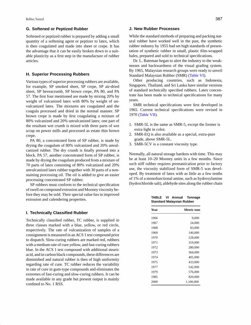
P1: GQQ/GLT P2: GRB Final Pages
Encyclopedia of Physical Science and Technology EN014B-670 July 28, 2001 16:50
Rubber, Natural 387
G. Softened or Peptized Rubber
Softened or peptized rubber is prepared by adding a smallquantity of a softening agent or peptizer to latex, whichis then coagulated and made into sheet or crepe. It hasthe advantage that it can be easily broken down to a suit-able plasticity as a first step in the manufacture of rubberarticles.
H. Superior Processing Rubbers
Various types of superior processing rubbers are available,for example, SP smoked sheet, SP crepe, SP air-driedsheet, SP heveacrumb, SP brown crepe, PA 80, and PA57. The first four mentioned are made by mixing 20% byweight of vulcanized latex with 80% by weight of un-vulcanized latex. The mixtures are coagulated and thecoagula processed and dried in the normal manner. SPbrown crepe is made by first coagulating a mixture of80% vulcanized and 20% unvulcanized latex; one part ofthe resultant wet crumb is mixed with three parts of wetscrap on power mills and processed as estate thin browncrepe.
PA 80, a concentrated form of SP rubber, is made bydrying the coagulum of 80% vulcanized and 20% unvul-canized rubber. The dry crumb is finally pressed into ablock. PA 57, another concentrated form of SP rubber, ismade by drying the coagulum produced from a mixture of70 parts of latex consisting of 80% vulcanized and 20%unvulcanized latex rubber together with 30 parts of a non-staining processing oil. The oil is added to give an easierprocessing concentrated SP rubber.
SP rubbers must conform to the technical specificationof swell on compound extrusion and Mooney viscosity be-fore they may be sold. Their special value lies in improvedextrusion and calendering properties.
I. Technically Classified Rubber
Technically classified rubber, TC rubber, is supplied inthree classes marked with a blue, yellow, or red circle,respectively. The rate of vulcanization of samples of aconsignment is measured in an ACS 1 test compound priorto dispatch. Slow-curing rubbers are marked red, rubberswith a medium rate of cure yellow, and fast-curing rubbersblue. In the ACS 1 test compound with additional stearicacid, and in carbon black compounds, these differences arediminished and natural rubber is then of high uniformityregarding rate of cure. TC rubber reduces the variabilityin rate of cure in gum-type compounds and eliminates theextremes of fast-curing and slow-curing rubbers. It can bemade available in any grade but present output is mainlyconfined to No. 1 RSS.
J. New Rubber Processes
While the standard methods of preparing and packing nat-ural rubber have worked well in the past, the syntheticrubber industry by 1955 had set high standards of presen-tation of synthetic rubber in small, plastic film-wrappedbales, prepared and sold to technical specifications.
Dr. L. Bateman began to alert the industry to the weak-nesses and backwardness of the visual grading system.By 1965, Malaysian research groups were ready to unveilStandard Malaysian Rubber (SMR) (Table VI).
Other producing countries, such as Indonesia,Singapore, Thailand, and Sri Lanka have similar versionsof standard technically specified rubbers. Latex concen-trate has been made to technical specifications for manyyears.
SMR technical specifications were first developed in1965. Current technical specifications were revised in1970 (Table VII).
1. SMR-5L is the same as SMR-5, except the former isextra light in color.
2. SMR-EQ is also available as a special, extra-puregrade, above SMR-5L.
3. SMR-5CV is a constant viscosity type.
Normally, all natural storage hardens with time. This maybe at least 10–20 Mooney units in a few months. Sincesuch stiff rubber requires premastication prior to factoryuse, the viscosity stabilized form of SMR-5 was devel-oped. By treatment of latex with as little as a few tenthsof 1% of a monofunctional amine, such as hydroxylamine(hydrochloride salt), aldehyde sites along the rubber chain
TABLE VI Annual TonnageStandard Malaysian Rubber
Year Metric tons
1966 9,000
1967 24,000
1968 83,000
1969 140,000
1970 228,000
1971 319,000
1972 280,000
1973 364,000
1974 405,000
1975 433,000
1977 542,000
1979 576,000
1985 820,000
2000 1,100,000

P1: GQQ/GLT P2: GRB Final Pages
Encyclopedia of Physical Science and Technology EN014B-670 July 28, 2001 16:50
388 Rubber, Natural
TABLE VII SMR Technical Specifications
Maximum limits 5La 5a 10 20 50
Dirt content (%) 0.05 0.05 0.10 0.20 0.50
Ash content (%) 0.60 0.60 0.75 1.00 1.50
Nitrogen content (%) 0.65 0.65 0.65 0.65 0.65
Volatile matter (%) 1.00 1.00 1.00 1.00 1.00
PRI (min)b 60. 60. 50. 40. 30.
Wallace plasticity (min) 30. 30. 30. 30. 30.
Color (Lovibond) 6. — — — —
a Restricted entirely to whole field latex origin.b Plasticity retention index, based on Wallace. Dirt is that retained on
a 44-µm aperture mesh.
are blocked, and prevented from cross-linking or hydrogenbonding.
1. Heveacrumb Process
The Rubber Research Institute of Malaysia (RRIM) in-vented a mechanochemical method for making crumb rub-ber. The process utilizes an incompatible oil such as castoroil, added to latex at amounts less than 0.5%. The acid-coagulated slab passes through the usual creping rolls.A fine, rice-particle-size crumb is produced, rather thana sheet. The washed crumb is readily dried in trays orcontinuously on a belt moving through hot-air dryers.The “Hevea-crumb” is then compressed into small bales,polythene-film wrapped, and shipped on a 1-ton woodenpalletized crate or loose, in large containers.
High amounts of petroleum extending oils or carbonblack or both can also be incorporated within the latexbefore crumbling. Other materials, such as zinc stearateor silicone oils, may be used. The excess of crumblingagents is removed during the washing process. Hence, noloss of natural tack or vulcanizate adhesion is encountered.
2. Comminution Process
Many producers and consumers prefer to use SMR madewithout a chemical crumbling agent. Such a strictly me-chanical process reduces the coagulum to pea-sized parti-cles with a rotary knife cutter or a granulator, such as theCumberland. Additionally, a hammermill may be used, toensure friability of any occasional large chunk. The largerchunks may not dry completely, and could result in whatis known as “wet knuckles.”
While the Heveacrumb process is primarily restricted tofield latex origin, the mechanical process usually employsnatural coagulum such as cup lump or tree lace. Otherwise,washing, drying, packing, and shipping steps are the sameas for Heveacrumb.
3. Extruder–Dryer Process
Very large production capacity can be obtained by us-ing extruder–driers, as with synthetic rubber. Wet coagu-lum is shredded, washed, put through a dewatering press(which reduces water content below 15%), then finallygoes through a second screw extruder. Heating during ex-trusion is regulated to remove residual water without ex-cessive heat oxidation of the rubber. One to three tons ofrubber can be processed each hour. Hence, only the largestproducer can economically use the process.
The SMR and other TSR types are compressed intobales of 70–75 lb each. These may measure 28 × 14 × 6.5or 22.5 × 15 × 7 in. Polythene-wrapped bales are stackedin a wooden pallet of 1100 mm (43.4 in.) × 1425 mm(58.1 in.) × 915 mm (36 in.) in height.
K. Speciality Rubbers
Several of the modified rubbers, such as AC, MG, SP, TC,PP, and skim, have been described earlier in the GreenBook of Specifications. Others are also available, somecommercially while others only experimentally. These in-clude the following.
1. Depolymerized Rubber
Depolymerized rubber has been liquefied by exposure forseveral hours at 140◦C. These can be vulcanized and areused for casting molds, potting compounds, and bindersfor abrasive wheels.
2. Cyclized Rubber
Cyclized rubber is prepared by treating sheeted rubber for1–4 hr at 125–145◦C in the presence of a catalyst. Catalystssuch as sulfuric acid, p-toluenesulfonic acid, phosphoricacid, and trichloroacetic acid may be used.
Amphoteric halides, such as the chlorides of variousheavy metals, including tin, antimony, aluminum, or tita-nium, may be utilized to produce cyclized rubber.
Excellent adhesives for rubber to metal may be madefrom cyclized rubber. Protective paints and coatings formetal have also been commercialized.
3. Chlorinated Rubber
Natural rubber can react by substitution or addition withchlorine. Passage of chlorine gas through a solution ofrubber in an inert solvent (such as carbon tetrachloride)at 80◦C is the usual manufacturing process. Removal ofsolvent by steam distillation leaves a fine, white powder.It is also possible to chlorinate latex directly, with suitableprotection against coagulation.
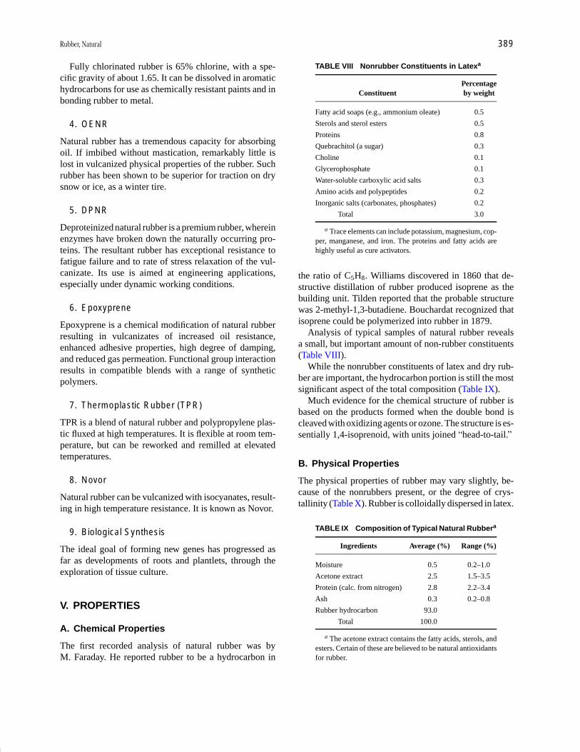
P1: GQQ/GLT P2: GRB Final Pages
Encyclopedia of Physical Science and Technology EN014B-670 July 28, 2001 16:50
Rubber, Natural 389
Fully chlorinated rubber is 65% chlorine, with a spe-cific gravity of about 1.65. It can be dissolved in aromatichydrocarbons for use as chemically resistant paints and inbonding rubber to metal.
4. OENR
Natural rubber has a tremendous capacity for absorbingoil. If imbibed without mastication, remarkably little islost in vulcanized physical properties of the rubber. Suchrubber has been shown to be superior for traction on drysnow or ice, as a winter tire.
5. DPNR
Deproteinized natural rubber is a premium rubber, whereinenzymes have broken down the naturally occurring pro-teins. The resultant rubber has exceptional resistance tofatigue failure and to rate of stress relaxation of the vul-canizate. Its use is aimed at engineering applications,especially under dynamic working conditions.
6. Epoxyprene
Epoxyprene is a chemical modification of natural rubberresulting in vulcanizates of increased oil resistance,enhanced adhesive properties, high degree of damping,and reduced gas permeation. Functional group interactionresults in compatible blends with a range of syntheticpolymers.
7. Thermoplastic Rubber (TPR)
TPR is a blend of natural rubber and polypropylene plas-tic fluxed at high temperatures. It is flexible at room tem-perature, but can be reworked and remilled at elevatedtemperatures.
8. Novor
Natural rubber can be vulcanized with isocyanates, result-ing in high temperature resistance. It is known as Novor.
9. Biological Synthesis
The ideal goal of forming new genes has progressed asfar as developments of roots and plantlets, through theexploration of tissue culture.
V. PROPERTIES
A. Chemical Properties
The first recorded analysis of natural rubber was byM. Faraday. He reported rubber to be a hydrocarbon in
TABLE VIII Nonrubber Constituents in Latexa
PercentageConstituent by weight
Fatty acid soaps (e.g., ammonium oleate) 0.5
Sterols and sterol esters 0.5
Proteins 0.8
Quebrachitol (a sugar) 0.3
Choline 0.1
Glycerophosphate 0.1
Water-soluble carboxylic acid salts 0.3
Amino acids and polypeptides 0.2
Inorganic salts (carbonates, phosphates) 0.2
Total 3.0
a Trace elements can include potassium, magnesium, cop-per, manganese, and iron. The proteins and fatty acids arehighly useful as cure activators.
the ratio of C5H8. Williams discovered in 1860 that de-structive distillation of rubber produced isoprene as thebuilding unit. Tilden reported that the probable structurewas 2-methyl-1,3-butadiene. Bouchardat recognized thatisoprene could be polymerized into rubber in 1879.
Analysis of typical samples of natural rubber revealsa small, but important amount of non-rubber constituents(Table VIII).
While the nonrubber constituents of latex and dry rub-ber are important, the hydrocarbon portion is still the mostsignificant aspect of the total composition (Table IX).
Much evidence for the chemical structure of rubber isbased on the products formed when the double bond iscleaved with oxidizing agents or ozone. The structure is es-sentially 1,4-isoprenoid, with units joined “head-to-tail.”
B. Physical Properties
The physical properties of rubber may vary slightly, be-cause of the nonrubbers present, or the degree of crys-tallinity (Table X). Rubber is colloidally dispersed in latex.
TABLE IX Composition of Typical Natural Rubbera
Ingredients Average (%) Range (%)
Moisture 0.5 0.2–1.0
Acetone extract 2.5 1.5–3.5
Protein (calc. from nitrogen) 2.8 2.2–3.4
Ash 0.3 0.2–0.8
Rubber hydrocarbon 93.0
Total 100.0
a The acetone extract contains the fatty acids, sterols, andesters. Certain of these are believed to be natural antioxidantsfor rubber.

P1: GQQ/GLT P2: GRB Final Pages
Encyclopedia of Physical Science and Technology EN014B-670 July 28, 2001 16:50
390 Rubber, Natural
TABLE X Some Physical Properties of NaturalRubber
Density 0.92
Refractive index (20◦C) 1.52
Coefficient of cubical expansion 0.00062 ◦C−1
Cohesive energy density 63.7 cal cm−3
Heat of combustion 10,700 cal g−1
Thermal conductivity 0.00032
Dielectric constant 2.37 cal s−1 cm−2 ◦C−1
Volume resistivity 1015 � cm−3
Dielectric strength 1,000 V mil−1
The average diameter of the latex particles is about 0.5µm.These particles are constantly in motion due to Brownianmovement. Each particle carries a negative electric charge,hence repelling each other and imparting stability to thelatex.
Natural rubber has both a sol and gel phase. Differ-ences are illustrated by their behavior to solvation. Highlybranched and lightly cross-linked gel resists solvation.Effective solvents for sol rubber are aliphatic and aromatichydrocarbons, chlorinated hydrocarbons, ethers, and car-bon disulfide. Nonsolvents include the lower alcohols,ketones, and certain esters.
The gel phase can be broken down into processiblerubber by mechanical shearing (mills, mixers, plastica-tors), or oxidation (assisted by heat), or chemically (pep-tizers). Rubber with high gel content is undesirable forcalendering, extrusion, or other fabrication processes.
1. Molecular Weight
Since rubber is a high-molecular-weight substance, rangesof values exist. Viscosity measurements of the dry rubberin shear are commonly used for relative assessment ofmolecular weight. Solution viscosity of the sol rubber inorganic solvents is also valuable.
Fractionation of rubber from solution reveals a rangeof polymers of varying molecular weight. Such fractionswill range from 200,000 to 400,000 in average molecularweight. The electron microscope has permitted measure-ment of the size of the molecular particles. Size/frequencydata can then be converted into a molecular weight distri-bution curve.
2. Crystallinity
There are two geometric configurations for natural rubber.These are the cis and trans isomeric forms. The normalstandard rubber, such as sheets and crepes, has the cisform. Balata or gutta-percha has the trans form. The lat-ter is hard and horny (crystalline) at room temperature.
When heated to about 80◦C, it becomes soft and tacky,indistinguishable from RSS at that temperature.
X-Ray diffraction studies of rubber in the unstretchedstate show a pattern of two concentric amorphous bands.When stretched to elongations short of rupture, such as700%, a fiber pattern is revealed. This consists of well-defined interference spots, called “crystallites.” The regu-lar arrangement indicates a unit cell with a repeat distancealong the chain structure of 8.1 A.
Raw rubber also shows a property called “racking.” Ifrubber is stretched repeatedly and rapidly near its ultimatebreaking elongation, followed each time by cooling (dry-ice bath), a highly fibrous structure develops. These fibersare very stiff and strong.
Other thermal effects are noted in rubber. When rubberis stretched rapidly, it heats up noticeably, contrary to thebehavior of most materials. Also, if rubber is stretchedunder a load, while held at the other end, it will retract asthe temperature is raised. These two thermal effects arejointly known as the Gough–Joule effect.
Finally, the prime importance of crystallization in nat-ural rubber is its self-reinforcing effect. As elongationincreases, so does crystallization, contributing to the ulti-mate tensile strength of natural rubber. It is this factor thatmakes natural rubber superior in strength or pure gum ornon-black-filled vulcanizates.
C. Biosynthesis
Natural rubber is structurally a simple example of terpenesand terpenoids, one of the most important groups of nat-ural products. Terpenes are related from the usually reg-ular union of the isopentane carbon skeleton of isoprene.This is described in the Ruzicka “Biogenetic IsopreneRule.” The important implication is that all terpenes andterpenoids have a common precursor. This was found to beisopent-3-enyl pyrophosphate (IPP), the addition productof pyrophosphoric acid to isoprene.
The search for such precursors only became possiblethrough isotopic labeling techniques. The conversion ofIPP into rubber is complex and detailed, best summarizedto include the role of acetic acid as a precursor in all rubberplants, and that of IPP as the monomer.
VI. PRODUCT USAGES
Although much blending of raw material is performedwith field latex and/or natural coagula, such as cup lump,efforts to attain uniformity are intensive. With standardrubber grades, such as sheets and crepes, the manufacturerstill resorts to blending of various shipment lots. Withtechnically specified rubbers, such blending is usually notnecessary.
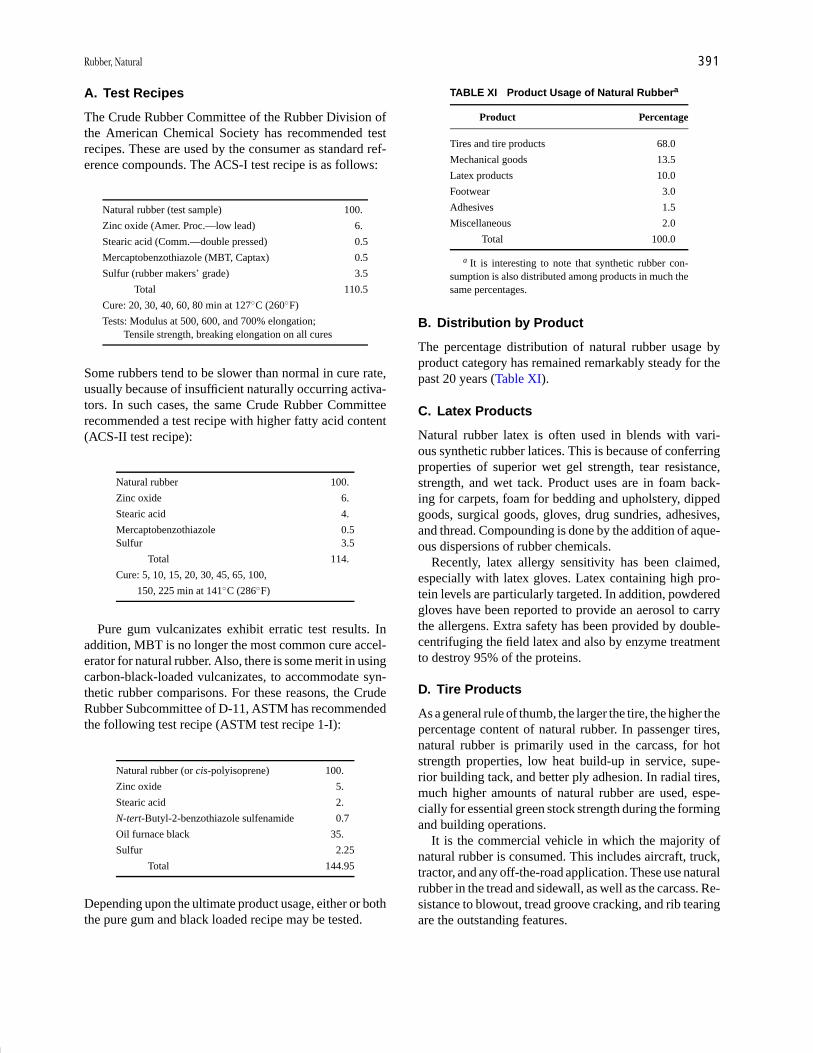
P1: GQQ/GLT P2: GRB Final Pages
Encyclopedia of Physical Science and Technology EN014B-670 July 28, 2001 16:50
Rubber, Natural 391
A. Test Recipes
The Crude Rubber Committee of the Rubber Division ofthe American Chemical Society has recommended testrecipes. These are used by the consumer as standard ref-erence compounds. The ACS-I test recipe is as follows:
Natural rubber (test sample) 100.
Zinc oxide (Amer. Proc.—low lead) 6.
Stearic acid (Comm.—double pressed) 0.5
Mercaptobenzothiazole (MBT, Captax) 0.5
Sulfur (rubber makers’ grade) 3.5
Total 110.5
Cure: 20, 30, 40, 60, 80 min at 127◦C (260◦F)
Tests: Modulus at 500, 600, and 700% elongation;Tensile strength, breaking elongation on all cures
Some rubbers tend to be slower than normal in cure rate,usually because of insufficient naturally occurring activa-tors. In such cases, the same Crude Rubber Committeerecommended a test recipe with higher fatty acid content(ACS-II test recipe):
Natural rubber 100.
Zinc oxide 6.
Stearic acid 4.
Mercaptobenzothiazole 0.5Sulfur 3.5
Total 114.
Cure: 5, 10, 15, 20, 30, 45, 65, 100,
150, 225 min at 141◦C (286◦F)
Pure gum vulcanizates exhibit erratic test results. Inaddition, MBT is no longer the most common cure accel-erator for natural rubber. Also, there is some merit in usingcarbon-black-loaded vulcanizates, to accommodate syn-thetic rubber comparisons. For these reasons, the CrudeRubber Subcommittee of D-11, ASTM has recommendedthe following test recipe (ASTM test recipe 1-I):
Natural rubber (or cis-polyisoprene) 100.
Zinc oxide 5.
Stearic acid 2.
N-tert-Butyl-2-benzothiazole sulfenamide 0.7
Oil furnace black 35.
Sulfur 2.25
Total 144.95
Depending upon the ultimate product usage, either or boththe pure gum and black loaded recipe may be tested.
TABLE XI Product Usage of Natural Rubbera
Product Percentage
Tires and tire products 68.0
Mechanical goods 13.5
Latex products 10.0
Footwear 3.0
Adhesives 1.5
Miscellaneous 2.0
Total 100.0
a It is interesting to note that synthetic rubber con-sumption is also distributed among products in much thesame percentages.
B. Distribution by Product
The percentage distribution of natural rubber usage byproduct category has remained remarkably steady for thepast 20 years (Table XI).
C. Latex Products
Natural rubber latex is often used in blends with vari-ous synthetic rubber latices. This is because of conferringproperties of superior wet gel strength, tear resistance,strength, and wet tack. Product uses are in foam back-ing for carpets, foam for bedding and upholstery, dippedgoods, surgical goods, gloves, drug sundries, adhesives,and thread. Compounding is done by the addition of aque-ous dispersions of rubber chemicals.
Recently, latex allergy sensitivity has been claimed,especially with latex gloves. Latex containing high pro-tein levels are particularly targeted. In addition, powderedgloves have been reported to provide an aerosol to carrythe allergens. Extra safety has been provided by double-centrifuging the field latex and also by enzyme treatmentto destroy 95% of the proteins.
D. Tire Products
As a general rule of thumb, the larger the tire, the higher thepercentage content of natural rubber. In passenger tires,natural rubber is primarily used in the carcass, for hotstrength properties, low heat build-up in service, supe-rior building tack, and better ply adhesion. In radial tires,much higher amounts of natural rubber are used, espe-cially for essential green stock strength during the formingand building operations.
It is the commercial vehicle in which the majority ofnatural rubber is consumed. This includes aircraft, truck,tractor, and any off-the-road application. These use naturalrubber in the tread and sidewall, as well as the carcass. Re-sistance to blowout, tread groove cracking, and rib tearingare the outstanding features.
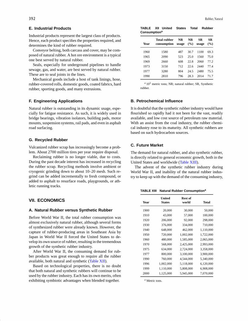
P1: GQQ/GLT P2: GRB Final Pages
Encyclopedia of Physical Science and Technology EN014B-670 July 28, 2001 16:50
392 Rubber, Natural
E. Industrial Products
Industrial products represent the largest class of products.Hence, each product specifies the properties required, anddetermines the kind of rubber required.
Conveyor belting, both carcass and cover, may be com-posed of natural rubber. A hot ore environment is a typicalone best served by natural rubber.
Seals, especially for underground pipelines to handlesewage, gas, and water, are best served by natural rubber.These are to seal joints in the lines.
Mechanical goods include a host of tank linings, hose,rubber-covered rolls, domestic goods, coated fabrics, hardrubber, sporting goods, and many extrusions.
F. Engineering Applications
Natural rubber is outstanding in its dynamic usage, espe-cially for fatigue resistance. As such, it is widely used inbridge bearings, vibration isolators, building pads, motormounts, suspension systems, rail pads, and even in asphaltroad surfacing.
G. Recycled Rubber
Vulcanized rubber scrap has increasingly become a prob-lem. About 2700 million tires per year require disposal.
Reclaiming rubber is no longer viable, due to costs.During the past decade interest has increased in recyclingthe rubber scrap. Recycling methods involve ambient orcryogenic grinding down to about 10–20 mesh. Such re-grind can be added incrementally to fresh compound, oradded to asphalt to resurface roads, playgrounds, or ath-letic running tracks.
VII. ECONOMICS
A. Natural Rubber versus Synthetic Rubber
Before World War II, the total rubber consumption wasalmost exclusively natural rubber, although several formsof synthesized rubber were already known. However, thecapture of rubber-producing areas in Southeast Asia byJapan in World War II forced the United States to de-velop its own source of rubber, resulting in the tremendousgrowth of the synthetic rubber industry.
After World War II, the consuming demand for rub-ber products was great enough to require all the rubberavailable, both natural and synthetic (Table XII).
Based on technological properties, there is no doubtthat both natural and synthetic rubbers will continue to beused by the rubber industry. Each has its own merits, oftenexhibiting symbiotic advantages when blended together.
TABLE XII United States Total RubberConsumptiona
Total rubber NR NR SR SRYear consumption usage (%) usage (%)
1960 1580 487 30.7 1100 69.3
1965 2090 523 25.0 1560 75.0
1969 2660 608 22.8 2060 77.2
1973 3150 712 22.6 2440 77.4
1977 3280 804 24.5 2480 75.5
1990 2810 796 28.3 2014 71.7
a 103 metric tons; NR; natural rubber; SR, Syntheticrubber.
B. Petrochemical Influence
It is doubtful that the synthetic rubber industry would haveflourished so rapidly had it not been for the vast, readilyavailable, and low cost source of petroleum raw material.With an assist from the coal industry, the rubber chemi-cal industry rose to its maturity. All synthetic rubbers arebased on such hydrocarbon sources.
C. Future Market
The demand for natural rubber, and also synthetic rubber,is directly related to general economic growth, both in theUnited States and worldwide (Table XIII).
The advent of the synthetic rubber industry duringWorld War II, and inability of the natural rubber indus-try to keep up with the demand of the consuming industry,
TABLE XIII Natural Rubber Consumptiona
United Rest ofYear States world Total
1900 20,000 30,000 50,000
1910 43,000 57,000 100,000
1920 206,000 92,000 298,000
1930 376,000 334,000 710,000
1940 648,000 462,000 1,110,000
1950 720,000 1,002,000 1,722,000
1960 480,000 1,585,000 2,065,000
1970 568,000 2,425,000 2,993,000
1975 634,000 2,724,000 3,358,000
1977 800,000 3,100,000 3,900,000
1990 760,000 4,544,000 5,340,000
1996 1,002,000 5,118,000 6,120,000
1999 1,110,000 5,808,000 6,908,000
2000 1,125,000 5,945,000 7,070,000
a Metric tons.
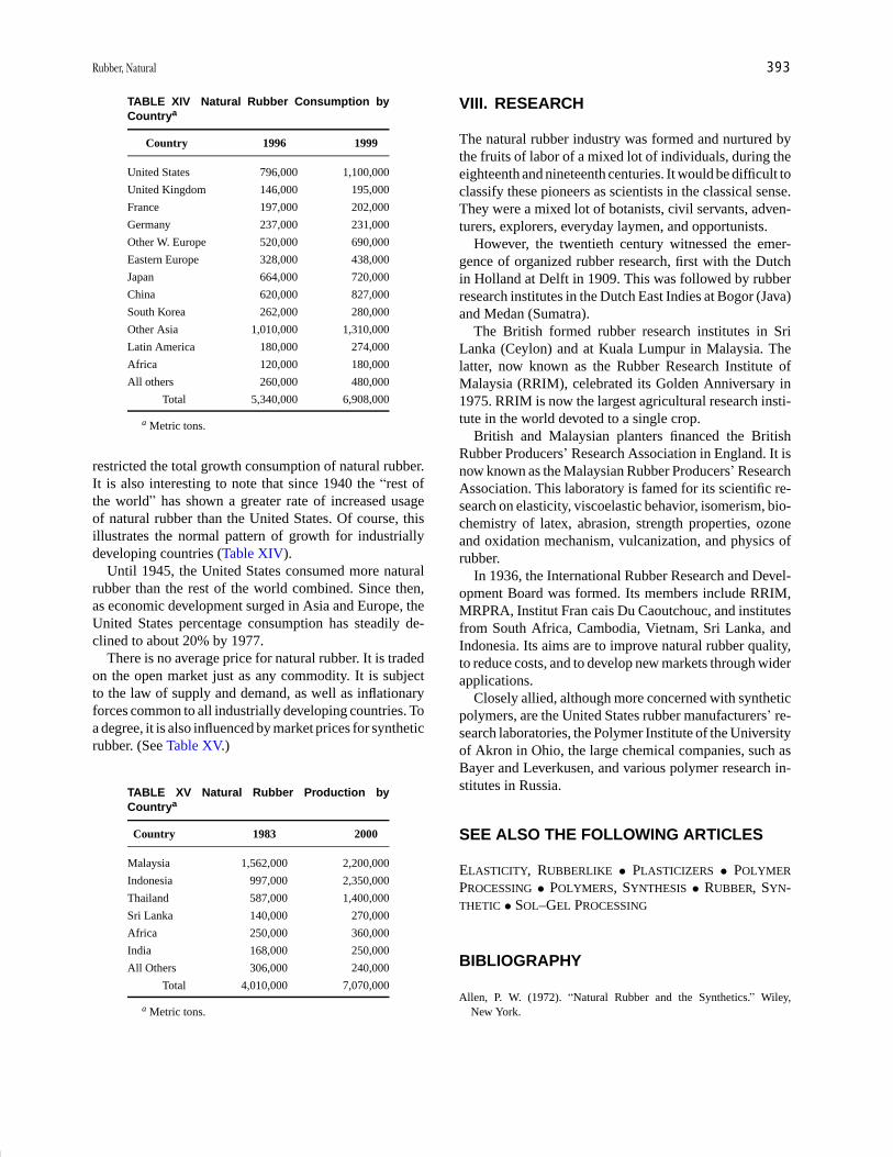
P1: GQQ/GLT P2: GRB Final Pages
Encyclopedia of Physical Science and Technology EN014B-670 July 28, 2001 16:50
Rubber, Natural 393
TABLE XIV Natural Rubber Consumption byCountrya
Country 1996 1999
United States 796,000 1,100,000
United Kingdom 146,000 195,000
France 197,000 202,000
Germany 237,000 231,000
Other W. Europe 520,000 690,000
Eastern Europe 328,000 438,000
Japan 664,000 720,000
China 620,000 827,000
South Korea 262,000 280,000
Other Asia 1,010,000 1,310,000
Latin America 180,000 274,000
Africa 120,000 180,000
All others 260,000 480,000
Total 5,340,000 6,908,000
a Metric tons.
restricted the total growth consumption of natural rubber.It is also interesting to note that since 1940 the “rest ofthe world” has shown a greater rate of increased usageof natural rubber than the United States. Of course, thisillustrates the normal pattern of growth for industriallydeveloping countries (Table XIV).
Until 1945, the United States consumed more naturalrubber than the rest of the world combined. Since then,as economic development surged in Asia and Europe, theUnited States percentage consumption has steadily de-clined to about 20% by 1977.
There is no average price for natural rubber. It is tradedon the open market just as any commodity. It is subjectto the law of supply and demand, as well as inflationaryforces common to all industrially developing countries. Toa degree, it is also influenced by market prices for syntheticrubber. (See Table XV.)
TABLE XV Natural Rubber Production byCountrya
Country 1983 2000
Malaysia 1,562,000 2,200,000
Indonesia 997,000 2,350,000
Thailand 587,000 1,400,000
Sri Lanka 140,000 270,000
Africa 250,000 360,000
India 168,000 250,000
All Others 306,000 240,000
Total 4,010,000 7,070,000
a Metric tons.
VIII. RESEARCH
The natural rubber industry was formed and nurtured bythe fruits of labor of a mixed lot of individuals, during theeighteenth and nineteenth centuries. It would be difficult toclassify these pioneers as scientists in the classical sense.They were a mixed lot of botanists, civil servants, adven-turers, explorers, everyday laymen, and opportunists.
However, the twentieth century witnessed the emer-gence of organized rubber research, first with the Dutchin Holland at Delft in 1909. This was followed by rubberresearch institutes in the Dutch East Indies at Bogor (Java)and Medan (Sumatra).
The British formed rubber research institutes in SriLanka (Ceylon) and at Kuala Lumpur in Malaysia. Thelatter, now known as the Rubber Research Institute ofMalaysia (RRIM), celebrated its Golden Anniversary in1975. RRIM is now the largest agricultural research insti-tute in the world devoted to a single crop.
British and Malaysian planters financed the BritishRubber Producers’ Research Association in England. It isnow known as the Malaysian Rubber Producers’ ResearchAssociation. This laboratory is famed for its scientific re-search on elasticity, viscoelastic behavior, isomerism, bio-chemistry of latex, abrasion, strength properties, ozoneand oxidation mechanism, vulcanization, and physics ofrubber.
In 1936, the International Rubber Research and Devel-opment Board was formed. Its members include RRIM,MRPRA, Institut Fran cais Du Caoutchouc, and institutesfrom South Africa, Cambodia, Vietnam, Sri Lanka, andIndonesia. Its aims are to improve natural rubber quality,to reduce costs, and to develop new markets through widerapplications.
Closely allied, although more concerned with syntheticpolymers, are the United States rubber manufacturers’ re-search laboratories, the Polymer Institute of the Universityof Akron in Ohio, the large chemical companies, such asBayer and Leverkusen, and various polymer research in-stitutes in Russia.
SEE ALSO THE FOLLOWING ARTICLES
ELASTICITY, RUBBERLIKE • PLASTICIZERS • POLYMER
PROCESSING • POLYMERS, SYNTHESIS • RUBBER, SYN-THETIC • SOL–GEL PROCESSING
BIBLIOGRAPHY
Allen, P. W. (1972). “Natural Rubber and the Synthetics.” Wiley,New York.

P1: GQQ/GLT P2: GRB Final Pages
Encyclopedia of Physical Science and Technology EN014B-670 July 28, 2001 16:50
394 Rubber, Natural
Babbit, R. D. (ed.) (1978). “The Vanderbilt Rubber Handbook,” R. T.Vanderbilt Company, Norwalk, Connecticut.
Bateman, L. (ed.) (1963). “Chemistry and Physics of Rubber-LikeSubstances,” Maclaren and Sons, London.
Blow, C. M. (ed.) (1971). ”Rubber Technology and Manufacture,”Butterworths, London.
Davis, C. C., and Blake, J. T. (1937). “Chemistry and Technology ofRubber,” Reinhold, New York.
LeBras, J. (1957). “Rubber, Fundamentals of Its Science and
Technology,” Chemical Publishing Co., New York.Morton, M. (ed.) (1973). “Rubber Technology,” Van Nostrand-Reinhold,
New York.Naunton, W. J. S. (ed.) (1961). “The Applied Science of Rubber,”
Edward Arnold, London.Noble, R. J. (1953). “Latex in Industry, 2nd ed.,” Hildreth Press, Bristol,
Connecticut.Stern, H. J. (1967). “Rubber: Natural and Synthetic, 2nd ed.,” Maclaren
and Sons, London.
P1: GQJ/GPA Final pages Qu: 00, 00, 00, 00
Encyclopedia of Physical Science and Technology EN014B-671 July 28, 2001 17:50
Rubber, SyntheticStephen T. SemegenSTS Technical Services
I. IntroductionII. Types
III. Production by TypesIV. Economics and Future Outlook
GLOSSARY
Catalyst Chemical that promotes the reaction of mon-omers into long polymer chains.
Coagulation Irreversible agglomeration of particles orig-inally dispersed in a rubber latex.
Comonomer One of the two or more monomer speciesthat react to form a polymer.
Copolymer Polymer formed from two or more types ofmonomers.
Diene polymer Polymer formed from one or more mon-omer species, at least one of which is a diolefin.
Formula (recipe) List of materials and description ofprocedure used to prepare a polymer.
Gel, latex Semisolid system consisting of a network ofaggregates in which a liquid is held.
Homopolymer Polymer formed from a single monomerspecies.
Polymer network Three-dimensional structure formedby chemical or physical linking of polymer chains.
Short stop Chemical that stops the polymerization pro-cess at the required chain length.
Viscoelasticity Combination of viscous and elastic prop-erties in a material with the relative contribution of eachdependent on time, temperature, stress, and strain rate.
SYNTHETIC RUBBER represents perhaps the greatestchemical engineering accomplishment of modern times.Although a laboratory curiosity 200 years ago, no typeof synthetic rubber was used commercially until almost1940. The loss of natural rubber sources during WorldWar II led to a tremendous industry and government pro-gram to develop poly(styrene-butadiene) rubber as a sub-stitute for natural rubber. By the end of the war in 1945,annual production exceeded 700,000 tons. Although a syn-thetic form of natural rubber exists that is chemically andphysically almost identical to cis-1,4-polyisoprene natu-ral rubber, there are at best 20 distinct chemical types ofsynthetic rubber available today. No one is better than allothers in an absolute sense. The best choice depends onthe properties required for end usage. Modern industryand technology could not exist as they are today withoutsynthetic rubber.
I. INTRODUCTION
A. Historical Background
The basic chemistry for synthetic rubber had been workedout in the early 1800s. In 1826, Michael Faraday hadshown natural rubber to consist of a hydrocarbon with five
395
P1: GQJ/GPA Final pages
Encyclopedia of Physical Science and Technology EN014B-671 July 28, 2001 17:50
396 Rubber, Synthetic
atoms of carbon for eight atoms of hydrogen. In 1860, G.Williams pyrolyzed raw natural rubber by dry distillationand called the distillate isoprene.
By 1887, W. A. Tilden in England, G. Bouchardat inFrance, and O. Wallach in Germany had some successin converting isoprene back into a rubberlike substance.Tilden was also able to obtain isoprene from turpentine. In1909, the first patent for synthetic rubber was granted toF. Hofman in Germany, who used isoprene obtained frommineral sources.
Kondakov, a Russian chemist, discovered that an elas-tic polymer could be more easily made from anotherhydrocarbon, dimethylbutadiene. In 1910, the Englishchemists F. E. Mathews and E. H. Strange and the Germanchemist G. C. Harries independently found that sodiumwas an effective catalyst to speed up the polymerizationprocess.
In Germany, lack of access to natural rubber sourcesduring World War I accelerated work on synthetic rubber.By 1916, Leverkusen was producing 150 tons of methylrubber from dimethyl-butadiene each month. After WorldWar I, Hermann Staudinger of Freiburg University inGermany discovered that rubber consists of moleculeswith very long chain lengths and high molecular weight.
After investigators switched to butadiene as the mon-omer and sodium as the catalyst, two new types werefound by 1929. One was a copolymer of butadiene andstyrene. The other was a copolymer of butadiene withacrylonitrile. Both were made in an aqueous emulsion,so that the rubber was obtained first as a latex and thencould be coagulated to yield a dry rubber. By the start ofWorld War II in Europe, Germany had a synthetic rubberproduction capacity of 175,000 tons per year in 1939. InRussia, synthetic rubber production reached 90,000 tonsin 1939.
In the United States, the first commercial efforts wereconcentrated on oil-resistant types of rubber, which nat-ural rubber and poly(butadiene-styrene) rubber are not.In 1927, J. C. Patrick produced a rubber by reactingethylene dichloride with sodium tetrasulfide. This is nowthe polysulfide class of elastomers. In 1931, Du Pontintroduced commercially the polymers of chloroprene(2-chloro-1,3-butadiene). Popular legend attributes earlylaboratory discovery to Father Nieuwland at Notre DameUniversity.
In 1937, W. J. Sparks and R. M. Thomas in-vented poly(isobutylene-isoprene), or butyl rubber, at theStandard Oil Company in New Jersey. By 1939, the B. F.Goodrich Company in Akron, Ohio, began production ofpoly(butadiene-acrylonitrile), or Ameripol rubber. AfterWorld War II arrived, the rest became history. By 1945, aturning point was reached that proved to be of major sig-nificance to the rubber industry, and indeed to all industry.
B. Chronological Discovery of Types
The early history of synthetic rubber development hasbeen mentioned. Perhaps the synthesis of a polyisoprene in1887 in the laboratory was the first step in a long journey.Certainly, the production of the Buna rubbers in 1929 wasa major first leap. The United States’ entry with polysul-fide rubber in 1927 and chloroprene rubber in 1931 was asignificant commercial advance. A quantum breakthroughwas, of course, the establishment of the giant styrene-butadiene rubber plants in the United States during the1940s. Since then, there have been a host of different syn-thetic rubber types developed, each with its own specificcombination of properties and uses.
1. Silicone Rubber
First patent application for silicone elastomers was in1944. Original suppliers were the General Electric Com-pany and the Dow Corning Corporation. Their uniqueproperties stem from a silicone backbone instead of anorganic carbon–carbon backbone.
2. Polyacrylic Rubber
Homopolymers of esters of acrylic acid were developedduring World War II by the B. F. Goodrich Company andregional laboratories of the U.S. Department of Agricul-ture. In 1948, B. F. Goodrich commercialized copolymersof the ester types with reactive halogen-containing types.The latter are useful for vulcanizing sites.
3. Fluorocarbon Elastomers
The fluorocarbon elastomers are based primarily on vinyli-dene fluoride and hexafluoropropylene. These were de-veloped originally by the Kellogg Company in the 1950s.Current producers are the 3M Company and Du Pont in theUnited States, Japan, Italy, and Russia are also producers.
4. Polybutadiene
Polybutadiene (PB) made in an aqueous solution is notnew. However, PB rubber made in an organic solvent so-lution system with stereospecific catalysts is much morescientifically and commercially important. These werethe polymerization catalyst systems discovered by KarlZiegler in Germany and by Giulio Natta in Italy.
Phillips Petroleum Company announced high cis-polybutadiene rubber in 1956.
5. Polyisoprene
Stereoregular polyisoprene was first commercialized bythe Shell Chemical Company in 1960. This was quickly

P1: GQJ/GPA Final pages
Encyclopedia of Physical Science and Technology EN014B-671 July 28, 2001 17:50
Rubber, Synthetic 397
followed by Goodyear and Goodrich-Gulf, although SamHorne had successfully obtained high cis-1,4 polyiso-prene in 1955. This was the first truly synthetic “naturalrubber.”
6. Poly(ethylene-propylene) and Terpolymers
The copolymers of ethylene and propylene are normallycrystalline plastics or resins. However, Karl Ziegler andGiulio Natta were able to choose catalysts that producedan amorphous structure with rubbery properties. By 1961,elastic poly(ethylene-propylene) (EPM) was available insmall quantities. In 1962, a third monomer was added.This is usually a diene, which permits conventional sulfurvulcanization. Commercial production followed in 1963in the United States.
II. TYPES
There is only one chemical type of natural rubber, cis-1,4-polyisoprene. In contrast, there are many different chem-ical types of synthetic rubber. Such types can compriserepeating chains of one, two, or even three monomers ofdifferent chemical and physical properties. In recent years,the use of blends of different synthetic rubbers has greatlyincreased. Often, a symbiotic improvement in physicalproperties and end product performance has resulted.
A. Poly(styrene-butadiene) and Polybutadiene
The copolymer of styrene and butadiene is called poly(styrene-butadiene) (SBR). It consists approximately of25% of styrene units distributed among 75% of butadieneunits in the polymer chain. It is the most widely used typeof synthetic rubber in the world; it also surpasses the totalusage of natural rubber. (See Table I.) It is interesting tonote that by the mid-1960s, total volume usage of syntheticrubber finally exceeded that of natural rubber worldwide.
TABLE I Consumption of Synthetic Rubber (SR) and NaturalRubber (NR) Worldwide
Year SR NR Total (metric tons)
1900 — 50,000 50,000
1920 — 300,000 300,000
1940 100,000 1,100,000 1,200,000
1950 700,000 1,600,000 2,300,000
1960 1,700,000 2,100,000 3,800,000
1970 4,600,000 2,300,000 6,900,000
1980 8,600,000 3,200,000 11,800,000
1996 9,560,000 6,120,000 15,680,000
2000 10,976,000 7,070,000 18,046,000
Actually, in North America that crossover had occurredby 1955.
Polybutadiene comes in a variety of types. These mayhave low to high cis contents. They may be made in organicsolvent solution or in aqueous emulsions. They possess thehighest resilience of any rubber, even including naturalrubber. However, its most important use is to blend withSBR or natural rubber because of its superiority for abra-sion resistance and low temperature resistance. As such,its use is highly desirable in tire treads. It is also capableof absorbing very high amounts of petroleum oils with-out undergoing a serious drop in the level of its beneficialphysical properties. This is most helpful as a cost-reducingfactor.
B. Polychloroprene
Polychloroprene (CR) is similar to isoprene in its chemicalstructure. The main difference is a chlorine atom in placeof a methyl group as a side chain. This confers greaterresistance to oil and solvents than does SBR or naturalrubber. It is also more resistant to aging and weathering.However, it is less resistant to stiffening at low tempera-tures. It also has a degree of flame resistance.
C. Poly(acrylonitrile-butadiene)
Nitrile rubber (NBR) is a copolymer of acrylonitrile andbutadiene in which the acrylonitrile content may vary from18 to 40%. The higher the acrylonitrile content, the betterthe oil resistance, which is still better than that for chloro-prene. Its heat aging resistance is also better, but not itsresistance to weathering. Low temperature resistance alsobecomes poorer with increasing acrylonitrile content.
D. Poly(isobutylene-isoprene)
Poly(isobutylene-isoprene) (IIR) is a solution polymer, of-ten called butyl rubber. The isoprene content ranges onlyfrom 1 to 4%. The latter is present to permit vulcaniza-tion with sulfur. Its outstanding property is its very lowpermeability to air and other gases. Its resistance to agingand weathering is very good, but it has a low degree ofresilience and poor low-temperature properties.
In addition, butyl rubber is incompatible with other rub-bers and will not covulcanize. This problem can be over-come to a degree by a small degree of reaction with chlo-rine or bromine to form halogenated butyl rubber.
E. Poly(ethylene-propylene) and Terpolymers
Copolymers of ethylene and propylene can be randomlyformed from 40:60 to 70:30 ratios. These are called

P1: GQJ/GPA Final pages
Encyclopedia of Physical Science and Technology EN014B-671 July 28, 2001 17:50
398 Rubber, Synthetic
poly(ethylene-propylene) (EPM) rubbers and can only bevulcanized with peroxides. Terpolymers may be madeby adding a small amount of a diene. This can be 1,4-hexadiene, dicyclo-pentadiene, or ethylidene norbornene.Such rubbers are called EPDM rubbers and can then bevulcanized with sulfur. Both EPM and EPDM rubbers areexcellent for heat aging and weathering. Their resistanceto low temperatures is also quite good. In addition, theylend themselves to very high extension with hydrocarbonoils without a high degree of loss in physical properties.In addition, a moderate amount of these rubbers can beblended with other rubbers satisfactorily.
F. Specialty Polymers
There are several synthetic rubbers whose volume usageis not very large but that fill very important roles.
1. Fluorocarbon Elastomers
The most common of the fluorocarbon elastomers (CFM)are based on vinylidene fluoride, hexafluoropropylene,and tetrafluoromethylene. These are expensive rubbers,ranging upward from about $15 per pound. In addition,their specific gravity is almost double that of other syn-thetic rubbers. Their main virtue lies in their heat resis-tance above 200◦C and their extremely good resistance tocorrosive chemicals. Most of these types do not have goodresistance to low temperatures.
2. Silicone Rubbers
Silicone (SI) rubbers are not considered to be carbon or-ganic compounds. Based on alternate atoms of silicon andoxygen, they are most useful for their wide operating tem-perature range, from below −100◦C to above +200◦C. Inaddition, they have excellent electrical insulating proper-ties, excellent resistance to many chemicals, and a propertyof being very unsticky.
3. Polysulfide Rubber
Polysulfide (T) rubbers are the reaction products of an or-ganic dihalide and sodium polysulfide. The FA type is acopolymer of ethylene dichloride and dichloroethyl for-mal. The ST type is a polymer of dichloroethyl formal with2% of trichloropropane. Further treatment produces thiolgroups. Zinc oxide is most commonly used as the vulcan-izing agent. Paraquinone dioxime may also be used withzinc oxide. The rubbers are very resistant to most classesof organic solvents. Resistance to aging and weatheringis also excellent, as is its impermeability to gases. It alsohas a strong, characteristic sulfurous odor.
TABLE II U.S. Consumption of Synthetic Rubber(1985)
Type Metric tons % Total
SBR 1,960,000 59
Polybutadiene 560,000 17
Polychloroprene 175,000 5
Nitrile 95,000 3
Butyl 190,000 6
EPDM 190,000 6
Polyisoprene 90,000 3
Others 40,000 1
Total 3,300,000 100
4. Polyacrylates
The polyacrylates (ACM) are highly heat- and oil-resistantpolymers. They were developed specifically for use inseals for the automotive industry. Most commonly usedrubbers employ ethyl acrylate with 1 to 5% of a chlorinecontaining cure site, such as 2-chloroethyl vinyl ether.Strong bases, such as polyamines, are the vulcanizingagents. Alkali metal stearates with sulfur have been usedpredominantly. Resistance to heat, aging, and weather-ing is also excellent. Due to a sluggish state of cure,post-tempering in a hot-air oven is often used to increaseresilience.
5. Others
In recent years, a host of other synthetic rubbers havebeen developed. These include the fluorosilicones,polyepichlorhydrin types, chlorosulfonated polyethylene(CSM), millable polyurethanes (Ue), vinyl acetate ethy-lene rubber (EVAC), and a large class of thermoplasticelastomers (TPE). The last is expected to have a brightfuture, due to the ease with which it is processed and fab-ricated into products. Since the materials do not requirevulcanization, residual scrap can be recycled. Styreneblock copolymers with dienes were the earliest commer-cial types. These are polystyrene hard segments connectedby a rubbery linear segment of polybutadiene, polyiso-prene, or polyisobutylene. (See Table II.)
III. PRODUCTION BY TYPES
Reference has been made to polymerization processes forsynthetic rubbers. Economic production requires a low-cost, plentiful raw material supply; a fast and controllablepolymerization process; the ability to stop the reaction atthe desired molecular weight or chain length; recovery of
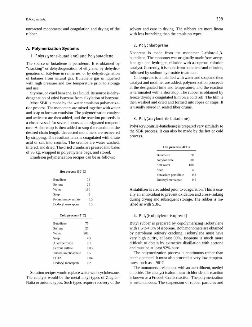
P1: GQJ/GPA Final pages
Encyclopedia of Physical Science and Technology EN014B-671 July 28, 2001 17:50
Rubber, Synthetic 399
unreacted monomers; and coagulation and drying of therubber.
A. Polymerization Systems
1. Poly(styrene-butadiene) and Polybutadiene
The source of butadiene is petroleum. It is obtained by“cracking” or dehydrogenation of ethylene, by dehydro-genation of butylene in refineries, or by dehydrogenationof butanes from natural gas. Butadiene gas is liquefiedwith high pressure and low temperature prior to storageand use.
Styrene, or vinyl benzene, is a liquid. Its source is dehy-drogenation of ethyl benzene from alkylation of benzene.
Most SBR is made by the water emulsion polymeriza-tion process. The monomers are mixed together with waterand soap to form an emulsion. The polymerization catalystand activator are then added, and the reaction proceeds ina closed vessel for several hours at a designated tempera-ture. A shortstop is then added to stop the reaction at thedesired chain length. Unreacted monomers are recoveredby stripping. The resultant latex is coagulated with diluteacid or salt into crumbs. The crumbs are water washed,filtered, and dried. The dried crumbs are pressed into balesof 35 kg, wrapped in polyethylene bags, and stored.
Emulsion polymerization recipes can be as follows:
Hot process (50◦C)
Butadiene 75
Styrene 25
Water 180
Soap 5
Potassium persulfate 0.3
Dodecyl mercaptan 0.5
Cold process (5◦C)
Butadiene 75
Styrene 25
Water 200
Soap 4.5
Alkyl peroxide 0.1
Ferrous sulfate 0.03
Trisodium phosphate 0.5
EDTA 0.04
Dodecyl mercaptan 0.2
Solution recipes would replace water with cyclohexane.The catalyst would be the metal alkyl types of Ziegler–Natta or anionic types. Such types require recovery of the
solvent and care in drying. The rubbers are more linearwith less branching than the emulsion types.
2. Polychloroprene
Neoprene is made from the monomer 2-chloro-1,3-butadiene. The monomer was originally made from acety-lene gas and hydrogen chloride with a cuprous chloridecatalyst. Currently, it is made from butadiene and chlorine,followed by sodium hydroxide treatment.
Chloroprene is emulsified with water and soap and thencatalyst and modifier are added, polymerization proceedsat the designated time and temperature, and the reactionis terminated with a shortstop. The rubber is obtained byfreeze drying a coagulated film on a cold roll. The film isthen washed and dried and formed into ropes or chips. Itis usually stored in sealed fiber drums.
3. Poly(acrylonitrile-butadiene)
Poly(acrylonitrile-butadiene) is prepared very similarly tothe SBR process. It can also be made by the hot or coldprocess.
Hot process (50◦C)
Butadiene 70
Acrylonitrile 30
Soft water 180
Soap 4
Potassium persulfate 0.3
Dodecyl mercaptan 0.5
A stabilizer is also added prior to coagulation. This is usu-ally an antioxidant to prevent oxidation and cross-linkingduring drying and subsequent storage. The rubber is fin-ished as with SBR.
4. Poly(isobutylene-isoprene)
Butyl rubber is prepared by copolymerizing isobutylenewith 1.5 to 4.5% of isoprene. Both monomers are obtainedby petroleum refinery cracking. Isobutylene must havevery high purity, at least 99%. Isoprene is much moredifficult to obtain by extractive distillation with acetoneand must be at least 92% pure.
The polymerization process is continuous rather thanbatch operated. It must also proceed at very low tempera-tures, such as −96◦C.
The monomers are blended with an inert diluent, methylchloride. The catalyst is aluminum trichloride; the reactionis known as a Friedel–Crafts reaction. The polymerizationis instantaneous. The suspension of rubber particles and
P1: GQJ/GPA Final pages
Encyclopedia of Physical Science and Technology EN014B-671 July 28, 2001 17:50
400 Rubber, Synthetic
liquid medium is dumped into hot water. Methyl chlorideand unreacted monomers are recovered and stored. Thewet crumbs are dried by passage through extruder milldriers, weighed, and baled.
5. Poly(ethylene-propylene) and Terpolymers
Both EPM and EPDM polymers are also prepared in asolvent solution, usually in hexane. The catalysts are acombination of metal alkyls and transition metal halides.Complete dryness is necessary, since moisture destroysthe catalysts. In fact, the polymerization reaction is ter-minated by the addition of water or alcohol. Oil is addedat this point, if the rubber is to be an oil-extended type.The rubber solution is then coagulated into crumbs byagitation in boiling water. The hexane solvent is recov-ered by distillation, while the rubber is dried by pas-sage through extruder driers. It is then compressed into75-lb bales measuring 7 × 14 × 28 in. The bales arewrapped in polyethylene film and packed in large unitcartons.
6. Fluorocarbon Elastomers
Fluorocarbon elastomers are produced by high-pressurepolymerization in an emulsion system using water as themedium. The emulsifier is a fluorocarbon soap. Persul-fates are used to initiate the reaction and polymerizationregulators are used to control the molecular weight of thepolymer. The production process is very similar to that forSBR.
7. Silicon Rubbers
Silicon polymers are prepared by a complex series ofchemical reactions. Starting materials are sand and alkylor aryl halides. Sand, preferably quartz, is first reducedto elemental silicon by heating with carbon in an electricfurnace. Eugene Rochow of the General Electric Com-pany developed the “direct process” of converting siliconinto silicone. This consists of heating silicon and copperpowder in a tube with methyl chloride gas to producea mixture of methyl trichlorosilane, dimethyl dichlorosi-lane, and trimethyl chlorosilane. Dimethyl dichlorosilaneis the basic ingredient for dimethyl silicone gums. It isseparated by fractional distillation. The silane is then hy-drolyzed to form a siloxane.
This siloxane is then converted to the silicone gum.This is done by a condensation polymerization reaction.Another process utilizes cyclic dimethyl siloxanes, whichcan be catalyzed with a base to open the ring and form ahigh-molecular-weight gum. Other types can be formedby adding phenyl or vinyl groups to the intermediates.
8. Polysulfides
The polymers are prepared by the addition of an or-ganic dihalide to a heated and stirred aqueous solutionof sodium polysulfide. Soaps or detergents are used toproduce small rubber crumbs upon coagulation with acid.The FA type is a linear copolymer of ethylene dichlo-ride and dichloroethyl formal. The ST type is principallydichloroethyl formal with 2% of trichloropropane.
Ethylene dichloride is made by reacting ethylene andchlorine. Dichloroethyl formal is made by reacting ethy-lene oxide with hydrochloric acid to form ethylene chloro-hydrin. The latter is then reacted with formaldehyde toform the formal. Sodium polysulfide is made by reactingsulfur with sodium hydroxide.
9. Polyacrylates
Polyacrylate elastomers can be prepared by any of sev-eral methods. These include the water emulsion system,suspension system, solvent solution method, or even themass (bulk homogenous) polymerization process. Mostare made by the water emulsion (latex) or the suspen-sion method. Peroxides or persulfate initiated free radicalsystems are most commonly used in the presence of heat.Polymerization is usually taken to completion. Coagula-tion is best with salts, followed by water washing anddrying with hot air, vacuum, or extrusion.
B. Chemical and Physical Properties
The properties of the raw, unvulcanized rubbers are notgenerally important, except for their specific gravity andmolecular weight. The latter is usually expressed in a rel-ative fashion, such as Mooney viscosity units. In addition,most synthetic rubbers are lacking in strength propertiesunless compounded with reinforcing fillers, such as car-bon blacks or fine-particle-size silicas.
1. Poly(styrene-butadiene)
Poly(styrene-butadiene) is most useful when sulfur vul-canized and reinforced with fillers. (See Table III.)
2. Polybutadiene
Polybutadiene is almost always used in blends with SBRor natural rubbers. This is primarily because of poor pro-cessing properties. However, it is the most resilient of allrubbers. (See Table IV.)
3. Polychloroprene
Polychloroprene rubber has a wide range of usefulproperties. However, none of them is supreme among
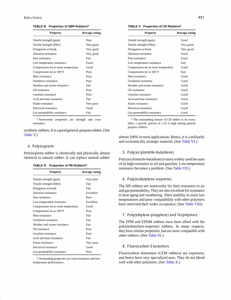
P1: GQJ/GPA Final pages
Encyclopedia of Physical Science and Technology EN014B-671 July 28, 2001 17:50
Rubber, Synthetic 401
TABLE III Properties of SBR Rubbersa
Property Average rating
Tensile strength (gum) Poor
Tensile strength (filler) Very good
Elongation at break Very good
Abrasion resistance Very good
Tear resistance Fair
Low temperature resistance Good
Compression set at room temperature Good
Compression set at 100◦F Poor
Heat resistance Poor
Oxidation resistance Poor
Weather and ozone resistance Fair
Oil resistance Poor
Gasoline resistance Poor
Acid and base resistance Fair
Flame resistance Very poor
Electrical resistance Good
Gas permeability resistance Fair
a Noteworthy properties are strength and wearresistance.
synthetic rubbers. It is a good general-purpose rubber. (SeeTable V.)
4. Polyisoprene
Polyisoprene rubber is chemically and physically almostidentical to natural rubber. It can replace natural rubber
TABLE IV Properties of PB Rubbersa
Property Average rating
Tensile strength (gum) Very poor
Tensile strength (filler) Fair
Elongation at break Fair
Abrasion resistance Excellent
Tear resistance Poor
Low temperature resistance Excellent
Compression set at room temperature Good
Compression set at 100◦F Poor
Heat resistance Fair
Oxidation resistance Fair
Weather and ozone resistance Fair
Oil resistance Poor
Gasoline resistance Poor
Acid and base resistance Fair
Flame resistance Very poor
Electrical resistance Good
Gas permeability resistance Poor
a Outstanding properties are wear resistance and low-temperature performance.
TABLE V Properties of CR Rubbersa
Property Average rating
Tensile strength (gum) Good
Tensile strength (filler) Very good
Elongation at break Very good
Abrasion resistance Good
Tear resistance Good
Low temperature resistance Fair
Compression set at room temperature Good
Compression set at 100◦F Fair
Heat resistance Good
Oxidation resistance Good
Weather and ozone resistance Good
Oil resistance Good
Gasoline resistance Good
Acid and base resistance Good
Flame resistance Good
Electrical resistance Good
Gas permeability resistance Good
a The outstanding feature of CR rubber is its versa-tility; a specific gravity of 1.25 is high among generalpurpose rubbers.
almost 100% in most applications. Hence, it is a militarilyand economically strategic material. (See Table VI.)
5. Poly(acrylonitrile-butadiene)
Poly(acrylonitrile-butadiene) is most widely used becauseof its high resistance to oil and gasoline. Low temperatureresistance becomes a problem. (See Table VII.)
6. Poly(isobutylene-isoprene)
The IIR rubbers are noteworthy for their resistance to airand gas permeability. They are also excellent for resistanceto heat aging and weathering. Their inability to resist lowtemperatures and poor compatibility with other polymershave restricted their wider acceptance. (See Table VIII).
7. Poly(ethylene-propylene) and Terpolymers
The EPM and EPDM rubbers have been allied with thepoly(isobutylene-isoprene) rubbers. In many respects,they have similar properties, but are more compatible withother rubbers. (See Table IX.)
8. Fluorocarbon Elastomers
Fluorocarbon elastomers (CFM rubbers) are expensive,and hence have very specialized uses. They do not blendwell with other polymers. (See Table X.)

P1: GQJ/GPA Final pages
Encyclopedia of Physical Science and Technology EN014B-671 July 28, 2001 17:50
402 Rubber, Synthetic
TABLE VI Properties of IR Rubbersa
Property Average rating
Tensile strength (gum) Good
Tensile strength (filler) Very good
Elongation at break Excellent
Abrasion resistance Fair
Tear resistance Good
Low temperature resistance Very good
Compression set at room temperature Very good
Compression set at 100◦F Poor
Heat resistance Poor
Oxidation resistance Poor
Weather and ozone resistance Poor
Oil resistance Poor
Gasoline resistance Poor
Acid and base resistance Good
Flame resistance Very poor
Electrical resistance Very good
Gas permeability resistance Fair
a Outstanding feature is its ability to replace or extendnatural rubber.
9. Silicon Rubbers
Silicon rubbers are usable over a much higher range oftemperatures than are carbon-based rubbers. Their elec-trical and chemical resistances also find wide applicationin aerospace and medical applications. (See Table XI.)
TABLE VII Properties of NBR Rubbersa
Property Average rating
Tensile strength (gum) Poor
Tensile strength (filler) Good
Elongation at break Good
Abrasion resistance Very good
Tear resistance Good
Low temperature resistance Fair–poor
Compression set at room temperature Fair
Compression set at 100◦F Fair
Heat resistance Good
Oxidation resistance Fair–good
Weather and ozone resistance Fair
Oil resistance Excellent
Gasoline resistance Excellent
Acid and base resistance Fair–good
Flame resistance Poor
Electrical resistance Poor
Gas permeability resistance Good
a Because of its solvent resistance, NBR is very usefulin seals, linings, printing rolls, and bearings.
TABLE VIII Properties of IIR Rubbersa
Property Average rating
Tensile strength (gum) Fair–poor
Tensile strength (filler) Fair
Elongation at break Good
Abrasion resistance Fair
Tear resistance Fair
Low temperature resistance Very poor
Compression set at room temperature Fair–poor
Compression set at 100◦F Good
Heat resistance Very good
Oxidation resistance Excellent
Weather and ozone resistance Excellent
Oil resistance Poor
Gasoline resistance Poor
Acid and base resistance Good
Flame resistance Poor
Electrical resistance Very good
Gas permeability resistance Excellent
a Low permeability to air makes IIR highly useful intire inner tubes and as an inner liner in tubeless tires.
10. Polysulfide Rubbers
The T rubbers are very inert to oils and many solvents.These are highly useful in building and civil engineeringuses. (See Table XII.)
TABLE IX Properties of EPDM Rubbersa
Property Average rating
Tensile strength (gum) Poor
Tensile strength (filler) Fair
Elongation at break Fair
Abrasion resistance Fair
Tear resistance Fair
Low temperature resistance Good
Compression set at room temperature Good
Compression set at 100◦F Very good
Heat resistance Very good
Oxidation resistance Excellent
Weather and ozone resistance Excellent
Oil resistance Poor
Gasoline resistance Poor
Acid and base resistance Excellent
Flame resistance Very poor
Electrical resistance Good
Gas permeability resistance Good
a Its resistance to weathering makes it a desirableblending material for sidewalls in tires.
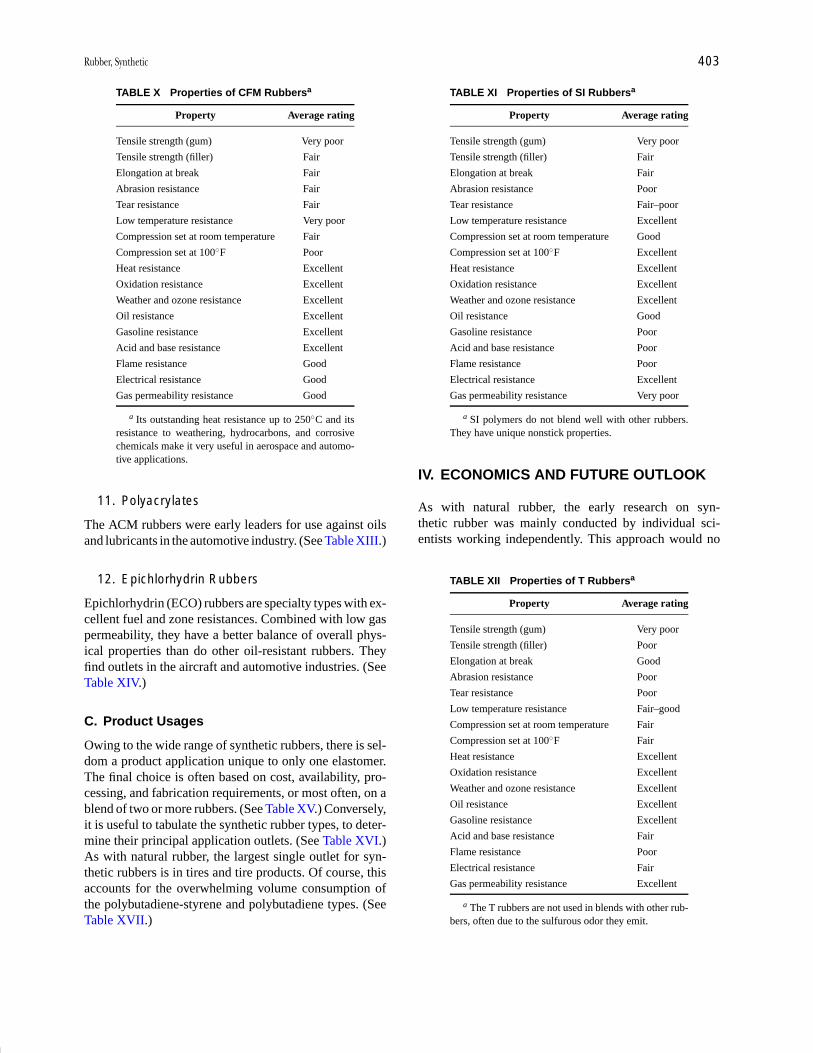
P1: GQJ/GPA Final pages
Encyclopedia of Physical Science and Technology EN014B-671 July 28, 2001 17:50
Rubber, Synthetic 403
TABLE X Properties of CFM Rubbersa
Property Average rating
Tensile strength (gum) Very poor
Tensile strength (filler) Fair
Elongation at break Fair
Abrasion resistance Fair
Tear resistance Fair
Low temperature resistance Very poor
Compression set at room temperature Fair
Compression set at 100◦F Poor
Heat resistance Excellent
Oxidation resistance Excellent
Weather and ozone resistance Excellent
Oil resistance Excellent
Gasoline resistance Excellent
Acid and base resistance Excellent
Flame resistance Good
Electrical resistance Good
Gas permeability resistance Good
a Its outstanding heat resistance up to 250◦C and itsresistance to weathering, hydrocarbons, and corrosivechemicals make it very useful in aerospace and automo-tive applications.
11. Polyacrylates
The ACM rubbers were early leaders for use against oilsand lubricants in the automotive industry. (See Table XIII.)
12. Epichlorhydrin Rubbers
Epichlorhydrin (ECO) rubbers are specialty types with ex-cellent fuel and zone resistances. Combined with low gaspermeability, they have a better balance of overall phys-ical properties than do other oil-resistant rubbers. Theyfind outlets in the aircraft and automotive industries. (SeeTable XIV.)
C. Product Usages
Owing to the wide range of synthetic rubbers, there is sel-dom a product application unique to only one elastomer.The final choice is often based on cost, availability, pro-cessing, and fabrication requirements, or most often, on ablend of two or more rubbers. (See Table XV.) Conversely,it is useful to tabulate the synthetic rubber types, to deter-mine their principal application outlets. (See Table XVI.)As with natural rubber, the largest single outlet for syn-thetic rubbers is in tires and tire products. Of course, thisaccounts for the overwhelming volume consumption ofthe polybutadiene-styrene and polybutadiene types. (SeeTable XVII.)
TABLE XI Properties of SI Rubbersa
Property Average rating
Tensile strength (gum) Very poor
Tensile strength (filler) Fair
Elongation at break Fair
Abrasion resistance Poor
Tear resistance Fair–poor
Low temperature resistance Excellent
Compression set at room temperature Good
Compression set at 100◦F Excellent
Heat resistance Excellent
Oxidation resistance Excellent
Weather and ozone resistance Excellent
Oil resistance Good
Gasoline resistance Poor
Acid and base resistance Poor
Flame resistance Poor
Electrical resistance Excellent
Gas permeability resistance Very poor
a SI polymers do not blend well with other rubbers.They have unique nonstick properties.
IV. ECONOMICS AND FUTURE OUTLOOK
As with natural rubber, the early research on syn-thetic rubber was mainly conducted by individual sci-entists working independently. This approach would no
TABLE XII Properties of T Rubbersa
Property Average rating
Tensile strength (gum) Very poor
Tensile strength (filler) Poor
Elongation at break Good
Abrasion resistance Poor
Tear resistance Poor
Low temperature resistance Fair–good
Compression set at room temperature Fair
Compression set at 100◦F Fair
Heat resistance Excellent
Oxidation resistance Excellent
Weather and ozone resistance Excellent
Oil resistance Excellent
Gasoline resistance Excellent
Acid and base resistance Fair
Flame resistance Poor
Electrical resistance Fair
Gas permeability resistance Excellent
a The T rubbers are not used in blends with other rub-bers, often due to the sulfurous odor they emit.
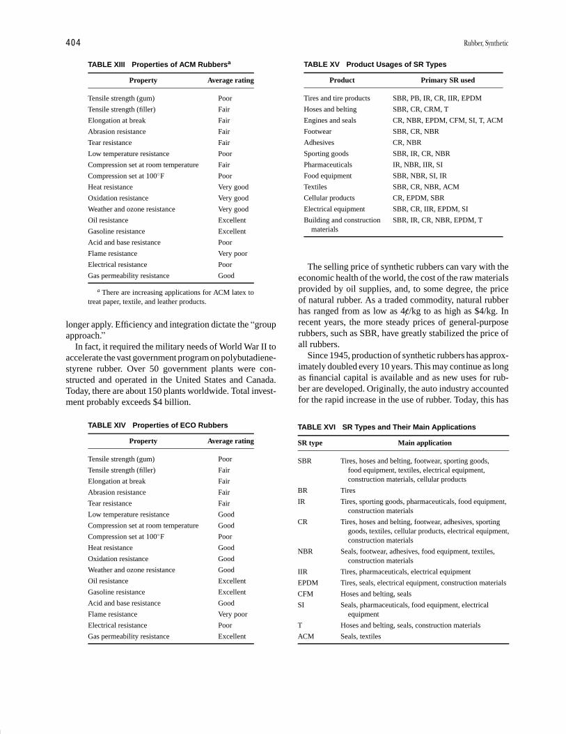
P1: GQJ/GPA Final pages
Encyclopedia of Physical Science and Technology EN014B-671 July 28, 2001 17:50
404 Rubber, Synthetic
TABLE XIII Properties of ACM Rubbersa
Property Average rating
Tensile strength (gum) Poor
Tensile strength (filler) Fair
Elongation at break Fair
Abrasion resistance Fair
Tear resistance Fair
Low temperature resistance Poor
Compression set at room temperature Fair
Compression set at 100◦F Poor
Heat resistance Very good
Oxidation resistance Very good
Weather and ozone resistance Very good
Oil resistance Excellent
Gasoline resistance Excellent
Acid and base resistance Poor
Flame resistance Very poor
Electrical resistance Poor
Gas permeability resistance Good
a There are increasing applications for ACM latex totreat paper, textile, and leather products.
longer apply. Efficiency and integration dictate the “groupapproach.”
In fact, it required the military needs of World War II toaccelerate the vast government program on polybutadiene-styrene rubber. Over 50 government plants were con-structed and operated in the United States and Canada.Today, there are about 150 plants worldwide. Total invest-ment probably exceeds $4 billion.
TABLE XIV Properties of ECO Rubbers
Property Average rating
Tensile strength (gum) Poor
Tensile strength (filler) Fair
Elongation at break Fair
Abrasion resistance Fair
Tear resistance Fair
Low temperature resistance Good
Compression set at room temperature Good
Compression set at 100◦F Poor
Heat resistance Good
Oxidation resistance Good
Weather and ozone resistance Good
Oil resistance Excellent
Gasoline resistance Excellent
Acid and base resistance Good
Flame resistance Very poor
Electrical resistance Poor
Gas permeability resistance Excellent
TABLE XV Product Usages of SR Types
Product Primary SR used
Tires and tire products SBR, PB, IR, CR, IIR, EPDM
Hoses and belting SBR, CR, CRM, T
Engines and seals CR, NBR, EPDM, CFM, SI, T, ACM
Footwear SBR, CR, NBR
Adhesives CR, NBR
Sporting goods SBR, IR, CR, NBR
Pharmaceuticals IR, NBR, IIR, SI
Food equipment SBR, NBR, SI, IR
Textiles SBR, CR, NBR, ACM
Cellular products CR, EPDM, SBR
Electrical equipment SBR, CR, IIR, EPDM, SI
Building and construction SBR, IR, CR, NBR, EPDM, Tmaterials
The selling price of synthetic rubbers can vary with theeconomic health of the world, the cost of the raw materialsprovided by oil supplies, and, to some degree, the priceof natural rubber. As a traded commodity, natural rubberhas ranged from as low as 4c//kg to as high as $4/kg. Inrecent years, the more steady prices of general-purposerubbers, such as SBR, have greatly stabilized the price ofall rubbers.
Since 1945, production of synthetic rubbers has approx-imately doubled every 10 years. This may continue as longas financial capital is available and as new uses for rub-ber are developed. Originally, the auto industry accountedfor the rapid increase in the use of rubber. Today, this has
TABLE XVI SR Types and Their Main Applications
SR type Main application
SBR Tires, hoses and belting, footwear, sporting goods,food equipment, textiles, electrical equipment,construction materials, cellular products
BR Tires
IR Tires, sporting goods, pharmaceuticals, food equipment,construction materials
CR Tires, hoses and belting, footwear, adhesives, sportinggoods, textiles, cellular products, electrical equipment,construction materials
NBR Seals, footwear, adhesives, food equipment, textiles,construction materials
IIR Tires, pharmaceuticals, electrical equipment
EPDM Tires, seals, electrical equipment, construction materials
CFM Hoses and belting, seals
SI Seals, pharmaceuticals, food equipment, electricalequipment
T Hoses and belting, seals, construction materials
ACM Seals, textiles

P1: GQJ/GPA Final pages
Encyclopedia of Physical Science and Technology EN014B-671 July 28, 2001 17:50
Rubber, Synthetic 405
TABLE XVII Product Usage of Synthetic Rubber
Product Percent
Tires and tire products 67
Mechanical goods 15
Footwear 5
Latex products 4
Drug sundries 4
Adhesives 2
Construction materials 2
Miscellaneous products 1
Total 100
extended to the space program, the construction indus-try, civil engineering uses, road constructions, agriculture,mining, and medicine. Already, the per capita consump-tion of rubber in the United States exceeds 20 kg per year.The role of synthetic rubber as a primary raw material andas a finished commodity in modern society appears to beassured and unchallenged. (See Table XVIII.)
Leaders in the research and production of synthetic rub-ber continue to be the major tire manufacturers, chemicalcompanies, and petroleum corporations worldwide. Most
TABLE XVIII Synthetic Rubber Consumptionby Countrya
Country 1996 2000
U.S. 2,187,000 2,565,000
Japan 1,124,000 1,179,000
Germany 478,000 535,000
France 436,000 455,000
S. Korea 440,000 425,000
Brazil 300,000 329,000
Italy 291,000 309,000
Taiwan 274,000 285,000
Canada 242,000 285,000
U.K. 230,000 226,000
Spain 201,000 230,000
Rest of World 3,357,000 3,720,000
Total 9,560,000 10,543,000
a Metric tons.
of these are loosely allied for promoting and providing in-formation about synthetic rubber within the InternationalInstitute of Synthetic Rubber Producers, Inc., headquar-tered in Houston, Texas.
Despite the development of polyisoprene, the questfor a synthetic replacement of natural rubber contin-ues to be advocated. Both economic and technical rea-sons have hindered such research. On the average, nat-ural rubber continually sells for 40% less than syntheticpolyisoprene.
SEE ALSO THE FOLLOWING ARTICLES
ELASTICITY • ELASTICITY, RUBBERLIKE • MACRO-MOLECULES, STRUCTURE • PLASTICIZERS • POLYMER
PROCESSING • POLYMERS, MECHANICAL BEHAVIOR •POLYMERS, RECYCLING • POLYMERS, SYNTHESIS • RUB-BER, NATURAL • THERMODYNAMICS
BIBLIOGRAPHY
Babbit, R. D. (ed.) (1978). “The Vanderbilt Rubber Handbook,” R. T.Vanderbilt, Norwalk, Connecticut.
Bateman, L. (ed.) (1963). “Chemistry and Physics of Rubber-like Sub-stances,” Maclaren and Sons, London.
Billmeyer, F. W., Jr., (1984). “Textbook of Polymer Science, 3rd ed.,”Wiley, New York.
Blackley, D. C. (1983). “Synthetic Rubbers: Their Chemistry and Tech-nology,” Applied Science Publishers, London.
Bueche, F. (1962). “Physical Properties of Polymers,” Interscience, NewYork.
Flory, P. J. (1953). “Principles of Polymer Chemistry,” Cornell UniversityPress, Ithaca, New York.
Kennedy, J. P., and Tornqvist, E. (eds.) (1968–1969). “Polymer Chem-istry of Synthetic Elastomers,” Vols. 1 and 2. Interscience, New York.
Morton, M. (1987). “Rubber Technology, 3rd ed.,” Van Nostrand-Reinhold, New York.
“Office of Rubber Reserve Reports,” Library of Congress, Washington,D. C. (1946–1950).
Penn, W. S. (1960). “Synthetic Rubber Technology,” Maclaren and Sons,London.
Stern, H. J. (1967). “Rubber: Natural and Synthetic, 2nd ed.,” Maclarenand Sons, London.
Whitby, G. S., Davis, C. G., and Dunbrook, R. F. (eds.) (1954). “SyntheticRubber,” Wiley, New York.