Embed Size (px)
Citation preview
QTouch Design Guide Atmel provides a QTouch library for the design of capacitive sensors using the QTouch technology. Implementation in Atmel Studio requires downloading QTouch libraries from the Atmel website. This enables the user to create a QTouch Executable Project in Atmel Studio 6 and use the built-in library functions. Following is the link to register and download the QTouch Library 5.0 The basic algorithm for designing a QTouch based sensor is :
1) Configure sensors as keys/rotors/sliders using : void qt_enable_key (channel_t channel, aks_group_t aks_group,threshold_t detect_threshold, hysteresis_t detect_hysteresis)
void qt_enable_rotor (channel_t from_channel, channel_t to_channel, aks_group_t aks_group, threshold_t detect_threshold ,hysteresis_t detect_hysteresis, resolution_t angle_resolution, uint8_t angle_hysteresis)
void qt_enable_slider (channel_t from_channel, channel_t to_channel, aks_group_t aks_group, threshold_t detect_threshold, hysteresis_t detect_hysteresis, resolution_t position_resolution, uint8_t position_hysteresis)
2) Set the touch parameters for the library – like the threshold level, detect integration values that set the number of counts the signal level should differ from the reference level in order to be registered as a touch, Maximum ON duration etc.
3) Initialize sensing using qt_init_sensing() to calibrate the channels and prepare the sensors for capacitive touch. It is a library defined function.
4) Initialize the timer ISR to run periodically and determine the time for a capacitive measurement.
5) Repeatedly call qt_measure_sensors() for capacitive measurements and to update the status flags. Library data structure qt_measure_sensors() takes the current time in milliseconds as the parameter and updates 10 flags.
6) Check if repeated measurements are required (QTLIB_BURST_AGAIN flag set to 1). If required, then measure sensors again.
7) Check the qt_touch_status[] to see if any sensors are in detect. If yes, then perform desired action. Else, repeat from step 5.
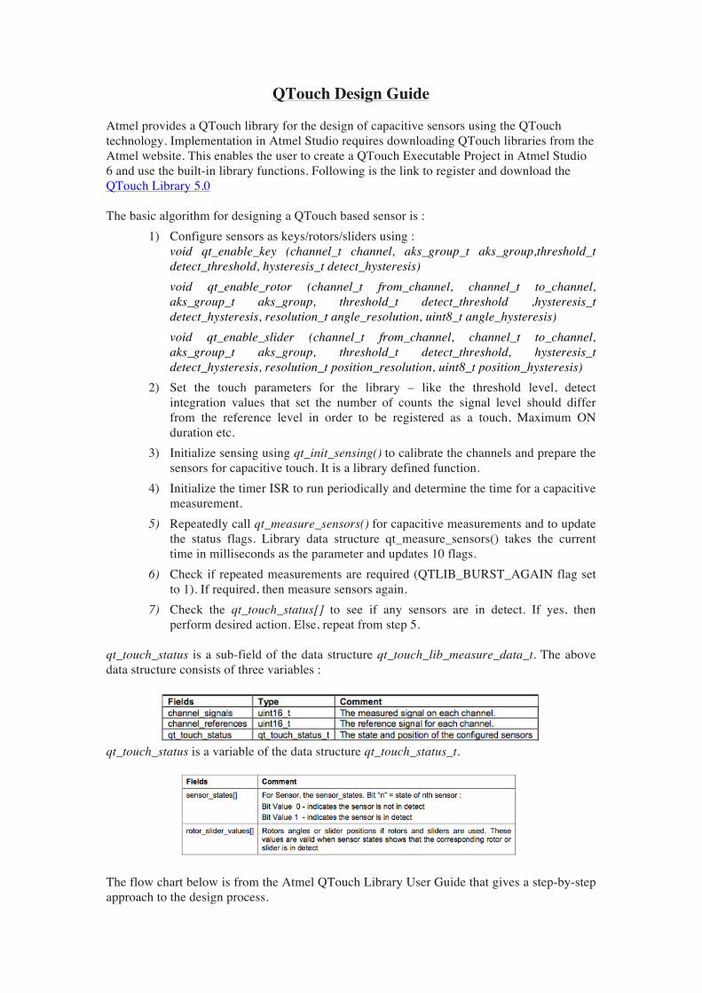
qt_touch_status is a sub-field of the data structure qt_touch_lib_measure_data_t. The above data structure consists of three variables :
qt_touch_status is a variable of the data structure qt_touch_status_t.
The flow chart below is from the Atmel QTouch Library User Guide that gives a step-by-step approach to the design process.

35
qt_reset_sensing()
qt_enable_xxx()
qt_init_sensing()
qt_set_parameters()
init_timer_isr()
check qt_touch_status
The host application (optionally) calls “qt_reset_sensing( )” to reset all channels and touch sensing parameters to their default states. This step is only required if the host wants to dynamically reconfigure the library at runtime
The host application calls “qt_enable_key( )”, “qt_enable_rotor( )” and/or “qt_enable_slider()” as required to configure the touch sensors
The host application qt_set_parameters() to initialize the threshold parameters for the library. If the user needs to change the thresholds, edit the global data structure qt_config_data prior to calling this API
The host application periodically calls “qt_measure_sensors( )” to make capacitive measurements.
check the global status variable “qt_touch_status” to see if any sensors are in detect, and the angle or position of any enabled rotors or sliders
The host application initializes the timer module required for capacitive measurement
The host application calls qt_init_sensing() to calibrate all the configured channels and prepare the sensors for capacitive measurement
qt_measure_sensors()
IsQTLIB_BURST_A
GAIN=1
No
Yes
Time-critical host application code
Check if multiple measurements are needed or not:To resolve calibration
To resolve DITo resolve positive recalibration
To compensate for drift
Non-Time critical host application code
Part of host application which cannot wait till multiple
measurements are complete (should be as minimal as possible)
Host application which can be executed after the completion of multiple measurements
for all the channels
Figure 5-6: Sequence of operations to add Touch capability

VISUAL GUIDE WITH SCREENSHOTS : Step 1 : In Atmel Studio 6, in the Start Page choose New Project. Create a GCC QTouch Executable Project and name it. Click OK. As an example, we named the project here LED_Blink.
Step 2 : Select the sensors you want to add in the project. The order in which the sensors are selected is important. The wizard allows a pin configuration only in increasing order. For example, a configuration of the sort Slider 0-2, Rotor 5-3 is not allowed. In this example, we chose 1 of each sensor. Select QTouch Technology and the device used. Click Next.

Step 3 : Select each sensor from the dropdown and assign a Sensor ID and define the size of each. The sensor ID assigned here will be used throughout to refer to the particular sensor.
For the Wheel and Slider, the orientation has to be selected in addition to the dimensions. In the example, a clockwise orientation is chosen for the Wheel and horizontal orientation with LeftToRight direction is chosen for the Slider.

The sensor IDs are chosen as 0 for button, 1 for the wheel and 2 for the Slider.
Step 4 : Next the ports used have to be selected. The SNSK port is connected to the series resistor and SNS port is connected through a capacitor to the series resistor. The sensors can be split over multiple ports (interport) or within the same port (intraport). Therefore, if the number of pins are sufficient, the SNSK and SNS ports can be one port. Some of the sensors can be moved to a new port pair SNSK2 and SNS2. In this case, we used port A as the SNSK1 and port B as the SNS. Click Next.

Step 5 : In this step, the exact Port pins have to be assigned to each sensor (as connected in hardware design). The pin numbers HAVE to be assigned in increasing order only. No sensor can have its channels connected to pins in decreasing order as mentioned before. However, it is not necessary that Port B pin 0 has to be connected to Port A pin 0; it can be any pin of A.
Step 6 : On clicking Next, the user is given an option to enable the debug interface and power optimization. The Debug interface enables the application to output measurement values to I/O pins, which can be used by a USB bridge to view the output on Hawkeye or QTouch Studio. It is disabled for this example. The power optimization is used to reduce the power usage of the system by about 40%. However, this turns of the spread spectrum feature of QTouch, which is used for better electromagnetic compatibility. We disabled this feature in the example.

Step 7 : On clicking Next, a summary is generated. Click Finish. The wizard generates the code with separate files for setting up the timer, configuring the touch sensors, initializing the MCU system clock etc. There is also a main.c file that provides the user with an infinite loop to perform desired actions. The first step now is to configure the sensors using the function config_sensors() in the file LED_Blink.qtdgn touch.c The user can change the resolution of the slider/rotor from 8-bit to lower. The hysteresis can also be modified.
Step 8 : The QTouch parameters can also be changed in the above file. The function qt_set_parameters() sets default values for the parameters. The user can change these values depending on the functionality and sensitivity desired. Refer to the end of this file for a description of what each parameter indicates. Step 9 : The ISR is initialized in the function init_timer_isr() in src QTouch init_mcu_atmega1284.c The timer is initialized to run at 50ms. This time can be changed if desired by the user depending on how often the touch measurement wants to be made.
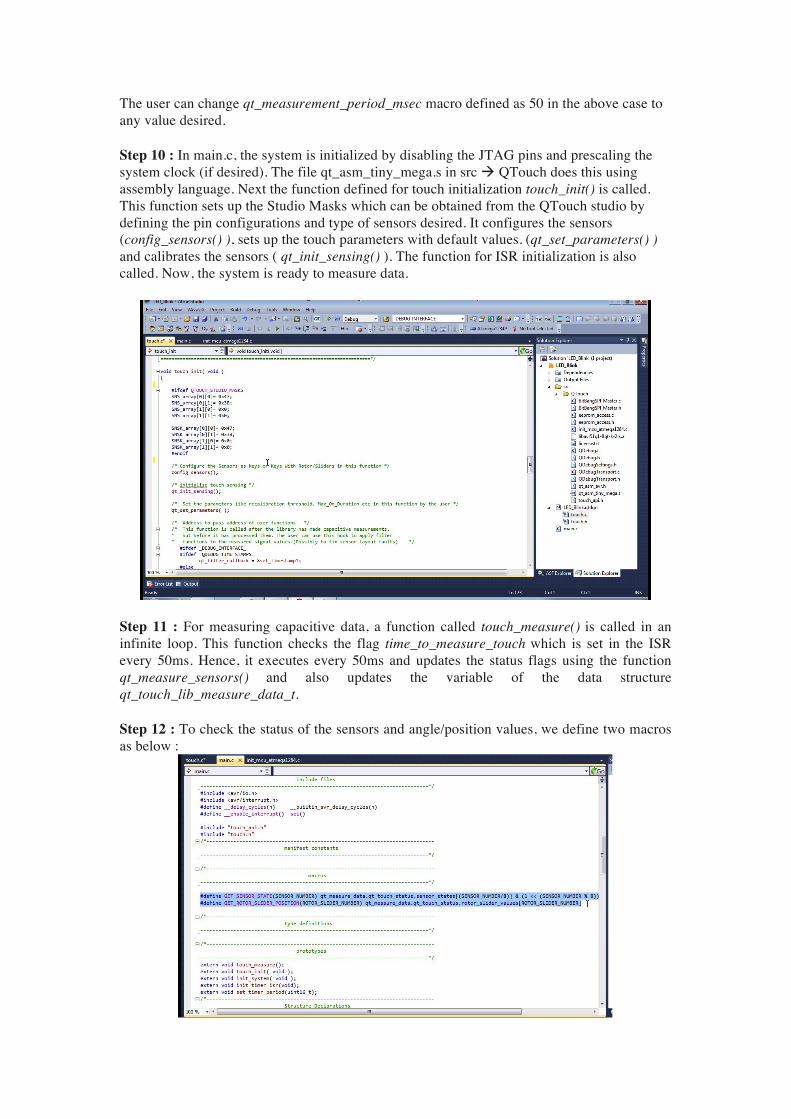
The user can change qt_measurement_period_msec macro defined as 50 in the above case to any value desired. Step 10 : In main.c, the system is initialized by disabling the JTAG pins and prescaling the system clock (if desired). The file qt_asm_tiny_mega.s in src QTouch does this using assembly language. Next the function defined for touch initialization touch_init() is called. This function sets up the Studio Masks which can be obtained from the QTouch studio by defining the pin configurations and type of sensors desired. It configures the sensors (config_sensors() ), sets up the touch parameters with default values. (qt_set_parameters() ) and calibrates the sensors ( qt_init_sensing() ). The function for ISR initialization is also called. Now, the system is ready to measure data.
Step 11 : For measuring capacitive data, a function called touch_measure() is called in an infinite loop. This function checks the flag time_to_measure_touch which is set in the ISR every 50ms. Hence, it executes every 50ms and updates the status flags using the function qt_measure_sensors() and also updates the variable of the data structure qt_touch_lib_measure_data_t. Step 12 : To check the status of the sensors and angle/position values, we define two macros as below :

GET_SENSOR_STATE(SENSOR_NUMBER) qt_measure_data is a variable of a library defined data structure qt_touch_lib_measure_data_t. In the above macro, we intend to get the touch status of a particular sensor and hence, the qt_touch_status[] consists of the information desired. As discussed earlier, qt_touch_status[] in itself is a structure that returns status of sensors and positions/angles of the slider/rotor. Therefore the macro qt_measure_data.qt_touch_status.sensor_status[...] returns 1 if the particular sensor is in detect and returns 0 if it is not touched. By checking the condition if(GET_SENSOR_STATE(SENSOR_NUMBER)), we know if a particular sensor has been touched. SENSOR_NUMBER here is the Sensor ID defined in the wizard. Accordingly, an action can be performed. GET_ROTOR_SLIDER_POSITION(SENSOR_NUMBER) It is defined as qt_touch_status.rotor_slider_values[….] returns the position of the slider sensor or the angle of the rotor slider. The SENSOR_NUMBER here is not the same as the sensor ID used in the macro GET_SENSOR_STATE. This sensor number is assigned only to Rotors/Sliders in the order in which they are defined. The sensor_number in this case is 0 for a rotor and 1 for a slider since the Slider was defined after the Rotor.
SENSOR SENSOR ID SENSOR_NUMBER for ROTOR_SLIDER_VALUES Button 0 -- Rotor 1 0 Slider 2 1
Therefore, a code as shown below is used to determine the sensors in detect and get the position or angle values on a scale of 0-255.


![Atmel AVR3008: QTouch Composer with QT600 …ww1.microchip.com/downloads/en/AppNotes/doc42045.pdfAtmel AVR3008: QTouch Composer with QT600-ATtiny88 Training Guide [APPLICATION NOTE]](https://img.pdfslide.us/doc/110x75/5f2dcfe81f190e6af826e298/atmel-avr3008-qtouch-composer-with-qt600-ww1-atmel-avr3008-qtouch-composer-with.jpg)


![Atmel QTouch Library PTC Release Note · Atmel PTC QTouch Library [RELEASE NOTES] Atmel-42544-PTC-QTouch-Library_ReleaseNotes 10 Fixed code generation logic for low power mega PTC](https://img.pdfslide.us/doc/110x75/60d59fbe8ad0960085088288/atmel-qtouch-library-ptc-release-note-atmel-ptc-qtouch-library-release-notes-atmel-42544-ptc-qtouch-libraryreleasenotes.jpg)