Embed Size (px)
Citation preview

�����������
����� ������
����� �
QSI CORPORATION2212 South West Temple #50
Salt Lake City, UTAH 84115-2648 USA
Phone 801-466-8770Fax 801-466-8792
Email [email protected] www.qsicorp.com
Manual 0049-080262E2 - Printed in USA
© Copyright QSI Corporation 1996-2000QTERM, QTERM-J10, QTERM-N15, JSETUP, and JDEMO are trademarks of QSI Corporation.

QSI LIMITED WARRANTY
QSI Corporation warrants that its products are free from defects in materials and manufacturing for a period of one year frodate of shipment. QSI further warrants that its products, when shipped, comply with the explicit product specifications con-tained in QSI's currently effective sales literature within the tolerances therein stated, determined in accordance with QSI'standard test procedures.
QSI will, at its option, repair or replace any product which does not comply with this warranty. The purchaser shall bear allcosts of shipping products for which warranty coverage is sought to QSI's factory in Salt Lake City, Utah, USA. Purchasershall pay all costs of removal and reinstallation of the product.
This warranty is voided by: (1) Any modification or attempted modification to the product done by anyone other than anauthorized QSI employee (other than user adjustments performed in accordance with QSI product manuals); (2) If powersupplied to the product exceeds the stated tolerance, or if the product is operated in environments exceeding the product'stated tolerance for temperature, humidity, moisture, radiation or electromagnetic fields; or (3) Any abuse, negligent han-dling or misapplication of the product.
THIS CONSTITUTES THE SOLE WARRANTY MADE BY QSI. THERE ARE NO OTHER WARRANTIES,EXPRESSED OR IMPLIED, WHICH EXTEND BEYOND THOSE DESCRIBED HEREIN OR TO ANYONEOTHER THAN THE ORIGINAL PURCHASER, INCLUDING THE IMPLIED WARRANTIES OF MERCHANT-ABILITY AND FITNESS FOR A PARTICULAR PURPOSE. IN NO EVENT SHALL QSI BE LIABLE FOR ANYINCIDENTAL OR CONSEQUENTIAL DAMAGES, OR FOR THE INFRINGEMENT OF ANY PATENT RIGHTOR THIRD PARTY RIGHTS DUE TO THE USE OF ITS PRODUCTS.
QSI REPAIR POLICY
Any product QSI manufactures but which is not under warranty may be returned to QSI, shipping prepaid, for an estimate ofrepair cost. QSI will provide the customer with such an estimate, and, at the customer's option, will either repair the productor return it to the customer. QSI may, at its option, either invoice the customer or require prepayment of repair and returnshipping charges. The customer is liable for shipping costs whether or not s/he requests QSI to repair the product.
Non-warranty repair charges include parts, labor and freight costs. Labor is charged at $100 per hour; the minimum repaircharge is $50. Products returned for warranty repair that have no malfunctions will incur the $50 minimum repair charge.
RETURN/RESTOCK POLICY
Stock QSI Products (holsters, cables, QTERM-J001, etc.) that have not been used may be returned within 90 days of ourinvoice date for a 15% restocking charge. Semi-Custom Products that have not been used may be returned within 90 days ofour invoice date for a restocking charge of 50%. (Please note that all QSI terminals ordered with a worksheet are semi-cus-tom, since the units are assembled to the worksheet specifications on receipt of your order.) Custom Products are non-return-able. In some instances QSI may offer salvage value for unused custom products; call for more information. QSI reserves theright to not accept any returns of any product after 90 days of our invoice date, or to accept them with a higher restockingcharge or for salvage value only.
FCC Notice
This equipment has been tested and found to comply with the limits for a Class A digital device, pursuant to Part 15 of the FCC rules. These limits are designed to provide reason-able protection against harmful interference when the equipment is operated in a commercial environment. This equipment generate s, uses and can radiate radio frequency energyand, if not installed and used in accordance with the instruction manual, may cause harmful interference to radio communications. Operation of this equipment in a residential areais likely to cause harmful interference in which case the user will be required to correct the interference at his own expense.

QSI Corporation • Fax 801-466-8792 • www.qsicorp.com • Phone 801-466-877
FOREWORD
The QSI Corporation QTERM-J10 and QTERM-N15 are data-entry terminals for industrial applications. The QTERM-J10 and QTERM-N15 are available with several options; this manual discusses all versions and their operations.
The QTERM-J10 and QTERM-N15 are CE Certified products. They have been assessed against the requirements of EN 50082-1: 1992, EN55022: 1987, and EN 60950 (including Amendments Numbers 1, 2, and 3). Based on conformity with these requirements, the QTERM-J10 and the QTERM-N15 are deemed in compliance with all applicable CE directives.
The sections of this manual are:
Chapter 1 Quick Start. If you wish to start using your QTERM immediately, this chapter will show you how to connect to the terminal and how to run the example software.
Chapter 2 QTERM Software. This chapter provides a detail ed listing of the QTERM commands and discusses how to use them.
Chapter 3 Using JDEMO and JSETUP. This chapter describes how to use the JDEMO program to demonstrate some of the features of the QTERM-J10 and QTERM-N15, and using the JSETUP program to set basic terminal parameters such as key-click and auto-wrap so that they become permanent power-up defaults.
Chapter 4 QTERM - J10/N15 Hardware. This chapter discusses the hardware of the QTERM-J10 handheld, QTERM-J10 panel-mount and QTERM-N15 panel-mount including dimensional drawings, interface specifications, connector pin assignments and environmental specifications.
Appendix A ASCII Chart. This is a true 7-bit ASCII chart, along with mnemonic definitions.
Appendix B QTERM Char acter Chart . This is a 256-character chart showing how the QTERM handles every character it receives. The lower half is similar to, but not the same as, the true ASCII chart in Appendix A.
Appendix C QTERM Command Summary. This is an abbreviated summary of QTERM software commands.
Please note that throughout this manual the character � represents the ESCAPE character, or ASCII 1Bh.

�� ��������� ������ ������
QSI Corporation • Fax 801-466-8792 • www.qsicorp.com • Phone 801-466-877

QSI Corporation • Fax 801-466-8792 • www.qsicorp.com • Phone 801-466-877
CONTENTS
CHAPTER 1. QUICK START ...............................................................................................................................................11.1 Power-On Setup ..............................................................................................................................................11.2 Connect The Communications Lines ..............................................................................................................11.3 Apply Power ...................................................................................................................................................21.4 Communicate ..................................................................................................................................................21.5 Running JDEMO ............................................................................................................................................2
CHAPTER 2. QTERM SOFTWARE ...........................................................................................................................................32.1 Operation .........................................................................................................................................................3
2.1.1 Handshaking .................................................................................................................................32.1.2 Commands vs. Default Parameters ...............................................................................................3
2.2 Software Commands .......................................................................................................................................32.2.1 Bell (^G) - 07h ..............................................................................................................................42.2.2 Backspace (^H) - 08h ....................................................................................................................42.2.3 Horizontal Tab (^I) - 09h ..............................................................................................................42.2.4 Line Feed (^J) - 0Ah .....................................................................................................................42.2.5 Vertical Tab (̂ K) - 0Bh ................................................................................................................42.2.6 Form Feed (^L) - 0Ch ...................................................................................................................52.2.7 Carriage Return (^M) - 0Dh .........................................................................................................52.2.8 XON (̂ Q) - 11h ............................................................................................................................52.2.9 XOFF (^S) - 13h ...........................................................................................................................52.2.10 Delete - 7Fh ..................................................................................................................................52.2.11 Cursor Up - � A ............................................................................................................................52.2.12 Cursor Down - � B .......................................................................................................................52.2.13 Cursor Right - � C ........................................................................................................................52.2.14 Cursor Left - � D ..........................................................................................................................52.2.15 Clear Screen - � E ........................................................................................................................52.2.16 Cursor Home - � H .......................................................................................................................52.2.17 Set Cursor Position - � I # * .........................................................................................................52.2.18 Erase to End of Screen - � J .........................................................................................................52.2.19 Erase to End of Line - � K ...........................................................................................................52.2.20 Set Contrast - � L # ......................................................................................................................52.2.21 Reset Terminal - � M ...................................................................................................................52.2.22 Query Version - � N .....................................................................................................................62.2.23 Buzzer On/Off/Beep - � O # ........................................................................................................62.2.24 Auto Wrap Mode - � R # ..............................................................................................................62.2.25 Auto Scroll M ode - � S # .............................................................................................................62.2.26 Auto Line Feed Mode - � T # .......................................................................................................62.2.27 Backlight On/Off/Toggle - � V # .................................................................................................62.2.28 Query Status - � W .......................................................................................................................72.2.29 Query Cursor Position - � X .........................................................................................................72.2.30 Query Character - � Y ..................................................................................................................72.2.31 Key Click/Repeat Mode - � a # ....................................................................................................72.2.32 Set Cursor Mode - � b # ...............................................................................................................72.2.33 Set Shift Mode - � c # ..................................................................................................................72.2.34 Save Configuration to EEPROM - � i ..........................................................................................72.2.35 Transmit Buffer Flush - � k ..........................................................................................................7

�� ��������� ������ ������
QSI Corporation • Fax 801-466-8792 • www.qsicorp.com • Phone 801-466-877
2.2.36 XON/XOFF Mode - � l # .............................................................................................................72.2.37 User Area Read/Write - � m # ......................................................................................................82.2.38 Restore Default Parameters - � r ..................................................................................................82.2.39 Verify Manufacturer ID Code - � u # * ........................................................................................82.2.40 Power-On Setup Mode - � x * ......................................................................................................8
2.3 Default Configuration .....................................................................................................................................8
CHAPTER 3. USING JDEMO AND JSETUP ............................................................................................................................93.1 JDEMO ...........................................................................................................................................................93.2 JSETUP ...........................................................................................................................................................9
3.2.1 Setting Parameters ........................................................................................................................93.2.2 Using JSETUP to Change Parameters ..........................................................................................93.2.3 Modifying the Data File ................................................................................................................93.2.4 Running JSETUP ..........................................................................................................................9
CHAPTER 4. QTERM-J10/N15 HARDWARE ........................................................................................................................114.1 QTERM-J10 Handheld Terminal .................................................................................................................114.2 QTERM-J10 Panel-Mount Terminal ............................................................................................................114.3 QTERM-N15 Panel Mount Terminal ...........................................................................................................124.4 Interface .......................................................................................................................................................14
4.4.1 EIA-232 Interface .......................................................................................................................144.4.2 EIA-422 Interface .......................................................................................................................144.4.3 5-volt Buffered Interface ............................................................................................................14
4.5 LCD Display .................................................................................................................................................144.6 Keypad ..........................................................................................................................................................154.7 Other Options ................................................................................................................................................15
4.7.1 Buzzer Option .............................................................................................................................154.7.2 Regulator Option .........................................................................................................................15
4.8 QTERM Specifications .................................................................................................................................15
APPENDIX A. ASCII CHART ................................................................................................................................................17
APPENDIX B. QTERM CHARACTER CHART ......................................................................................................................19
APPENDIX C. QTERM COMMAND SUMMARY ...................................................................................................................21

QSI Corporation • Fax 801-466-8792 • www.qsicorp.com • Phone 801-466-877
CHAPTER 1.
QUICK START
There are only four steps required to communicate with theQTERM-J10 or QTERM-N15:
� Use Power-On Setup to set the display contrast,baud rate and data format.
� Connect to your host transmit, receive and groundlines.
� Apply power.� Transmit and receive with the QTERM.
1.1 Power-On Setup
The Power-On Setup procedure is used to configure the QTERM's display contrast, baud rate and data format. You use three different QTERM keys to do this configuration:
'1' - this is the up key'2' - this is the down key'3' - this is the enter key
To perform the Power-On Setup follow these steps:
� Disconnect the power supply to the QTERM.
� Hold down any key and apply power to the QTERM(you do not need to connect the transmit and receivelines).
� The version of software in the QTERM will be dis-played for a few seconds, after which you can adjustthe display contrast.
� Set the desired display contrast using the up anddown keys. When the display is at a contrast youlike, press the enter key.
� Set the desired baud rate using the up and downkeys. When the desired baud rate is displayed, presthe enter key.
� Set the desired data format using the up and downkeys.
1.2 Connect The Communications Lines
When the desired data format is displayed, press the enterkey.The EIA-232 device has one transmit and one receiveline, while the EIA-422 device has two transmit and tworeceive lines.
Table 1-1 shows the connector pin assignments for both thehandheld and panel-mount QTERMs. The receive andtransmit directions shown in the table are with respect tothe QTERM. Refer to this table to connect your hostcommunications lines to the correct pins. Figure 1-1 showthe pin numbering of a modular connector (both jack andplug), and the panel mount interface plug.
(If you are using an IBM-style PC, you cannot connect anEIA-422 QTERM-J10 directly to the computer’s COMport; you must provide an interface device.)
����� ���� ��������
Figure 1-1. QTERM Connector Pin Assignments.

� ��������� ������ ������
QSI Corporation • Fax 801-466-8792 • www.qsicorp.com • Phone 801-466-877
1.3 Apply Power
Table 1-1 shows the pin assignments for the power andground lines. Connect your DC power supply to the appro-priate two pins.
WARNING: Power supplied to the QTERM must be froan SELV power source, and should have acurrent limit on its output of 5 Amperes. Ifyou did not order the regulator option, thesupply to the QTERM must provide a mini-mum of 4.75 volts DC and be limited to a
maximum of 5.25 volts DC. If you did order the regulatoroption, the supply to the QTERM must provide a minimuof 7.5 volts DC and be limited to a maximum of 24 voltDC. Limiting may be inherent to the supply, or may be pro-vided by supplementary overcurrent devices.
If the QTERM does not respond, or exhibits abnormalbehavior on power up, disconnect power and contact QSIfor technical support.
1.4 Communicate
At this point, characters which are transmitted by the host will be displayed on the QTERM display. If you press
keys on the keypad, the QTERM will transmit the appropri-ate codes to the host computer. Any software commandsent by the host will be processed by the QTERM.
1.5 Running JDEMO
To demonstrate some of the features of the QTERM, runthe JDEMO program included with this users manual:
� Connect your QTERM to the serial COM port on anIBM-style PC. (If you have an EIA-422 QTERM, youwill need to provide an interface unit such as QSI’QCOM-2; you cannot directly connect an EIA-422QTERM to the COM port on an IBM-style computer!)
� Copy the file JDEMO.EXE to your hard disk.
� Apply power to the QTERM.
� Run the JDEMO program.
� Follow the on-screen instructions to demonstrate theuse of some of the features of the QTERM terminal.
JDEMO will allow you to exercise many of the features ofthe QTERM. It includes a terminal emulator so that you canalso communicate directly with the terminal.
Table 1-1. QTERM Pin Assignments.
6-pin Modular Connector
DB9Female
Panel-Mount Molex Pin
QTERM EIA-232 Function
QTERM EIA-422 Function
1 3 1 receive +receive
2 6 2 no connection -receive
3 2 3 transmit +transmit
4 1 4 no connection -transmit
5 9 5 power power
6 5 6 ground ground
!

QSI Corporation • Fax 801-466-8792 • www.qsicorp.com • Phone 801-466-877
CHAPTER 2.
QTERM SOFTWARE
2.1 Operation
The operation of the QTERM is quite simple:
� Power is applied to the QTERM.
� Commands or data can be transmitted to the QTERM. Commands are executed as required; data is displayed.
� When a key is pressed, the QTERM transmits the appropriate character to the host.
The QTERM has many additional capabilities which areaccessed using software commands from the host which aredescribed in this chapter.
2.1.1 Handshaking
The QTERM has buffers for both receiving and transmit-ting characters. However, these buffers may not be largeenough for some applications. If this is the case for yourapplication, then your host must use XON/XOFF hand-shaking to make optimal use of the QTERM's capabilities.
The QTERM's transmit buffer (20 bytes long) is used whena host does not wish to receive characters for a period oftime. The host sends an XOFF character to the QTERM(13h). The QTERM starts placing characters into the trans-mit buffer rather than transmitting them. When the host iready to receive characters, it sends an XON character(11h), at which time the QTERM will start transmitting thecharacters in the buffer.
The QTERM's receive buffer is large enough to accept amaximum of 32 characters or software commands withoutoverrunning the buffer. However, some operations can takea longer time to execute, such as scrolling the entire screenup one line. In this case, the QTERM will send an XOFF tothe host when it has only eight bytes empty in its buffer.When it has processed input data to the point that the buffer
only has eight bytes used, it will send an XON, and the hostcan resume transmitting.
XON/XOFF handshaking can also be disabled (by softwarecommand) if you do not wish to use it. However, if you donot use handshaking, you must take extra care that you donot overrun the QTERM's receive buffer. The two easiestways to do this are to use a slower baud rate (which givethe QTERM more time to process each byte), or add delayto your code after each write to the QTERM.
2.1.2 Commands vs. Default Parameters
There are numerous parameters which can be changed bysoftware commands. For example, key repeat can be dis-abled by the Key Repeat/ Click On/Off command. Once aparameter has been changed by a software command, itdoes not get stored in EEPROM; therefore, when power iturned off, the new value is lost and when the terminal iturned on again, the default parameter value is re-loaded.
If you wish to have the parameter value permanently storedand used at power up, you can use the Save Configurationto EEPROM command. This saves all currently-set param-eters to the EEPROM, which makes them the currentpower-on defaults. If you wish to return to the factory-default settings for all parameters, you can use the RestoreFactory Defaults command. This will reset all parameters(except baud rate and data format) to a pre-defined defaultvalue, and also store these values in EEPROM as the cur-rent power-on defaults.
2.2 Software Commands
Once you have your host communicating with yourQTERM, you can program your host to control theQTERM using software commands. Table 2-1 lists thecommands available. Each command is discussed in detailbelow, and a command summary, including executiontimes, is given in Appendix C.

� ��������� ������ ������
QSI Corporation • Fax 801-466-8792 • www.qsicorp.com • Phone 801-466-877
The notation � in this chapter always means the one-byteASCII escape character (1Bh = 27 decimal).
Be sure to read the file READ.ME on your distribution diskfor any late changes to this manual.
2.2.1 Bell (^G) - 07h
This causes the buzzer to beep for one-half second. Notethat sending this command is identical to sending theBuzzer On/Off/Beep command (ESC O B).
2.2.2 Backspace (^H) - 08h
Causes a nondestructive backspace, i.e., characters are noterased as the cursor is backspaced over them. With autowrap mode off, the backspace stops at the left edge of thecurrent display line. With auto wrap mode on, the cursorwill wrap to the last position on the previous line. The com-mand is ignored if the cursor is at the home position. Seealso the Delete command (7Fh).
2.2.3 Horizontal Tab (^I) - 09h
Moves the cursor right to the next tab column. The tabspacing is every four columns.With auto wrap on, the cur-sor will wrap down to the first column in the line belowwhen it is tabbed beyond the last column in the current line.If auto wrap is off, the cursor will stop at the end of the cur-rent line. If auto scroll and auto wrap are both on, then thedisplay will scroll up as the cursor is tabbed beyond the lastcolumn in the last line.
2.2.4 Line Feed (^J) - 0Ah
Moves the cursor down one line without changing its hori-zontal position. When auto scroll mode is on and a line feedis performed on the last line, the display will scroll up withthe horizontal cursor position unaltered.
2.2.5 Vertical Tab (^K) - 0Bh
Performs the same function as Line Feed.
Table 2-1. QTERM-J10 and QTERM-N15 Software Commands.
Command Code Command Code
Bell (^G) 07h Reset Terminal � M
Backspace (^H) 08h Query Version � N
Horizontal Tab (^I) 09h Buzzer On/Off/Beep � O..
Line Feed (^J 0Ah Auto Wrap Mode � R..
Vertical Tab (^K) 0Bh Auto Scroll Mode � S..
Form Feed (^L) 0Ch Auto Line Feed Mode � T..
Carriage Return (^M) 0Dh Display Backlight On/Off/Toggle � V..
XON (DC1 or ^Q) 11h Query Status � W
XOFF (DC3 or ^S) 13h Query Cursor Position � X
Delete 7Fh Query Character � Y
Cursor Up � A Key Repeat/Click Mode � a..
Cursor Down � B Set Cursor Mode � b..
Cursor Right � C Set Shift Mode � c..
Cursor Left � D Save Config to EEPROM � i
Clear Screen � E Transmit Buffer Flush � k
Cursor Home � H XON/XOFF Mode � l..
Set Cursor Position � I.. User Area Read/Write � m..
Erase to End of Screen � J Restore Default Parameters � r
Erase to End of Line � K Verify MID Code � u..
Set Contrast � L.. Power-On Setup Mode � x..

��������� ������ ������
QSI Corporation • Fax 801-466-8792 • www.qsicorp.com • Phone 801-466-877
2.2.6 Form Feed (^L) - 0Ch
Performs the same function as Line Feed.
2.2.7 Carriage Return (^M) - 0Dh
Moves the cursor to left edge of the display on the currentline. If auto line feed mode is on, then the cursor moves tothe left edge of the next line. If auto scroll and auto linefeed are both on, a carriage return on the last line will causethe display to scroll up and the cursor to be positioned at theleft edge of the last line.
2.2.8 XON (^Q) - 11h
Enables the QTERM to transmit keys pushed after receiv-ing an XOFF. XON is used to re-enable QTERM transmission after an XOFF has disabled it, allowing handshakingwith the host system.
2.2.9 XOFF (^S) - 13h
Disables all QTERM transmission except for informationrequested via the Query Status command (ESC W). Afterreceiving an XOFF command, the QTERM stores charac-ters typed on the keypad in a transmit buffer. These charac-ters will be transmitted when an XON is received. If thebuffer becomes full before an XON is received, additionalcharacters which are typed will be ignored.
2.2.10 Delete - 7Fh
Delete works in the same way as Backspace (08h, ^H),except that characters are erased as the cursor moves overthem.
2.2.11 Cursor Up ���� A
Moves the cursor up one line without changing its horizon-tal position. Has no effect if the cursor is on the first line.
2.2.12 Cursor Down - ���� B
Moves the cursor down one line without changing its hori-zontal position. Has no effect if the cursor is on the last line.
2.2.13 Cursor Right - ���� C
Moves the cursor right one space without changing its ver-tical position. Has no effect if the cursor is at the right-mostposition on the current line.
2.2.14 Cursor Left - ���� D
Moves the cursor left one space without changing its verti-cal position. Has no effect if the cursor is at the left-mostposition on the current line.
2.2.15 Clear Screen - ���� E
Clears the display and moves the display cursor to home(the left-most position in the top line of the display).
2.2.16 Cursor Home - ���� H
Moves the cursor to home (top left) position on the display.
2.2.17 Set Cursor Position - ���� I # *
Positions the cursor to the specified location. The commandhas the form � I # *, where # sets the row and * sets the col-umn. For example, the string:
� I B D
sets the cursor to row 2 (third row) and column 4 (fifth col-umn). See Table 2-2 for a complete list of valid codes andcursor positions. (Note that rows are numbered 0 to 3, start-ing at the top, and columns are numbered 0 to 19, starting atthe left.)
2.2.18 Erase to End of Screen - ���� J
Erases from the current cursor position to the end of thescreen. The cursor position is unchanged.
2.2.19 Erase to End of Line - ���� K
Erases all displayed characters from the current cursor posi-tion to the end of the line. The cursor position is unchanged.
2.2.20 Set Contrast - ���� L #
This command sets the display contrast. It has the form � L#, where # is in the range of 40h to 7Fh ('@' to DEL). Thesmaller the ASCII value of the character, the lower the con-trast. The higher the ASCII value of the character, thehigher the contrast.
2.2.21 Reset Terminal - ���� M
Resets the QTERM to its power-up state. This includeclearing all input and output buffers and the display, andresetting all parameters to the default configuration.

� ��������� ������ ������
QSI Corporation • Fax 801-466-8792 • www.qsicorp.com • Phone 801-466-877
2.2.22 Query Version - ���� N
This tells the QTERM to transmit its software version to thehost. The version will consist of four ASCII characters inthe format vx.y, where x and y are single ASCII digits.
2.2.23 Buzzer On/Off/Beep - ���� O #
This command controls the buzzer. It has the form � O #,where # is:
@ - turn buzzer offA - turn buzzer on
B - beep for ½ second
The fixed duration beep command (ESC O B) is identical tosending a Bell command (07h, ^G).
2.2.24 Auto Wrap Mode - ���� R #
The auto wrap mode determines what happens when thecursor moves past the end of a line. With auto wrap off, thecursor stays at the last position in the line. With auto wrapon, the cursor moves down to the first position in the nextline.
If the cursor moves past the end of the last line, and autowrap is on, then the action depends on the auto scroll mode.If auto scroll is off, the cursor will wrap to the first positionof the line, but the display will not scroll. Otherwise, thedisplay will scroll, and the cursor will return to the firstposition in the last line.
Valid values for # are:
@ - auto wrap offA - auto wrap on
2.2.25 Auto Scroll Mode - ���� S #
Auto scroll mode determines what happens when the cursormoves past the end of the last line. With auto scroll off, thecursor will stay in the last position. With auto scroll on, thedisplay scrolls (i.e. every lines moves up, and the last linebecomes blank), and the cursor moves to the first positionin the last line.
Valid values for # are:
@ - auto scroll offA - auto scroll on
2.2.26 Auto Line Feed Mode - ���� T #
With auto line feed off, when a carriage return is receivedthe cursor returns to the first position in the currentline.With auto line feed on, the cursor moves to the firstposition in the next line, i.e. it acts as if both a carriagereturn and a linefeed had been received.
Valid values for # are:
@ - auto line feed offA - auto line feed on
2.2.27 Backlight On/Off/Toggle - ���� V #
This command turns the backlight on and off. Valid valuefor # are:
Table 2-2. Cursor Position and Query StatuCharacters.
ASCIIChar
Hex Value
Decimal Value
Query &Set CursorPosition
(row col)
Query Status(chars)
@ 40h 64 0 0 0
A 41h 65 1 1 1
B 42h 66 2 2 2
C 43h 67 3 3 3
D 44h 68 4 4
E 45h 69 5 5
F 46h 70 6 6
G 47h 71 7 7
H 48h 72 8 8
I 49h 73 9 9
J 4Ah 74 10 10
K 4Bh 75 11 11
L 4Ch 76 12 12
M 4Dh 77 13 13
N 4Eh 78 14 14
O 4Fh 79 15 15
P 50h 80 16 16
Q 51h 81 17 17
R 52h 82 18 18
S 53h 83 19 19
T 54h 84 20

��������� ������ ������ �
QSI Corporation • Fax 801-466-8792 • www.qsicorp.com • Phone 801-466-877
@ - backlight offA - backlight onB- backlight toggle
2.2.28 Query Status - ���� W
The Query Status command (�W) returns a character indi-cating the number of characters presently in the QTERM-J10 transmit buffer (0 to 20). Table 2-2 shows what charac-ter is returned for each number of characters in the transmitbuffer.
2.2.29 Query Cursor Position ���� X
Returns the cursor position as two ASCII characters. Thesetwo characters are defined in the same way as for the SetCursor Position (� I) command. See Table 2-2 for adetailed listing.
2.2.30 Query Character - ���� Y
Returns the character value for the character at the currentcursor position.
2.2.31 Key Click/Repeat Mode - ���� a #
This selectively enables and disables both key repeat andkey click. Valid values for # are:
@ - click off, repeat offA - click off, repeat onB - click on, repeat offC - click on, repeat on
Key clicks are 50 ms long; the key repeat rate is ten per sec-ond.
2.2.32 Set Cursor Mode - ���� b #
The QTERM cursor can be an underline cursor, a blockcursor, neither or both. When neither is selected, no cursoris visible to the user. Valid values for # are:
@ - block off, underline off (no cursor)A - block off, underline onB - block on, underline offC - block on, underline on
2.2.33 Set Shift Mode - ���� c #
The shift key on the QTERM can operate in one of twoways:
� FUNCTION MODE, where the shift key stays shiftedfor one additional key press only
� LOCK MODE, where the shift key stays shifted untilit is pressed a second time
To indicate shift status, the cursor will change to a blinkingblock when shifted, and go back to current cursor statuswhen not shifted. For either mode, this indicator can beenabled or disabled, and, if enabled, properly reflects thestate of the shift key. Valid values for # are:
@ - function mode, shift indicator enabledA - lock mode, shift indicator enabledB - function mode, shift indicator disabledC - lock mode, shift indicator disabled
Note that the shift indicator does not affect the shift opera-tion itself, only the status indicator. Also note that any timeyou are using the blinking block cursor, the shift indicatorwill not be available.
2.2.34 Save Configuration to EEPROM - ���� i
This command causes all parameter values to be stored toEEPROM. Any existing parameter values in the EEPROMwill be overwritten.
2.2.35 Transmit Buffer Flush - ���� k
If the host has transmitted an XOFF to the QTERM, and theuser has pressed any keys, this command will clear thebuffer, so that when the host sends XON to the QTERM,there will be nothing in the buffer for the QTERM to trans-mit to the host.
2.2.36 XON/XOFF Mode - ���� l #
This command enables or disables the XON/XOFF opera-tion of the QTERM. The valid values for # are:
@ - disable XON/XOFF operationA - enable XON/XOFF operation
If you disable XON/XOFF operation, then any keypressed by the user will be sent to the host immediately. If
� ��������� ������ ������
QSI Corporation • Fax 801-466-8792 • www.qsicorp.com • Phone 801-466-877
the host sends data fast enough to the QTERM to fill up thereceive buffer, additional characters will be ignored.
2.2.37 User Area Read/Write - ���� m #
This command allows you to store your own information(such as serial numbers or parameters) in the QTERM non-volatile EEPROM, then later read them from the terminal.There are two valid values for #:
@ - read user dataA - write user data (followed by data)
The QTERM can store a maximum of 16 bytes in the userdata area.
READ DATA: if # = '@', the QTERM will transmit the datain the user area to the host in the following format:
# . . . .
where # is a character in the range of 40h to 50h, and indi-cates that 0 to 16 bytes of user data will follow, and '. . . .' ithe corresponding number of user bytes. These bytes willbe exactly what was originally stored, so they may be any8-bit value. If # = '@' (0 bytes to follow), then there was nodata stored in the user area.
WRITE DATA: to write user data, use the format:
� m A # . . . .
where # is in the range of 41h to 50h ('A' to ‘P’), and indi-cates that from 1 to 16 bytes of data are to follow, and '. . . .' are the data bytes to be stored. These data bytes may be any8-bit value.
After the entire string has been received, the QTERM willrespond by transmitting one character to the host:
06h - Acknowledge character (ACK), data stored properly15h - Negative Acknowledge character (NAK), data not
stored
The only reason that the data would not be stored properlyis if there was a hardware failure.
2.2.38 Restore Default Parameters - ���� r
This command will load a set of factory-default values for
all parameters (except baud rate and data format) into mem-ory, and write them to EEPROM making them the currentpower-up settings (see section 2.3 for a list of the factorydefaults).
2.2.39 Verify Manufacturer ID Code - ���� u # *
This command is used to verify the Manufacturer ID (MID)Code which is pre-programmed into the terminal at the fac-tory. # and * can be any two bytes. When ordering aQTERM from the factory, the customer is given the optionto use this feature and will be assigned a two byte MIDcode. When this command is sent, along with two bytes, theterminal will compare them to its internally stored bytepair, and respond with one of the following:
06h - Acknowledge character (ACK), MID Code match.15h - Negative Acknowledge character (NAK), MID Code
does not match.
2.2.40 Power-On Setup Mode - ���� x *
This command can be used to enable or disable the power-on setup feature. In some cases, it may be desirable to dis-able the power-on setup in order to protect the current baudrate and data format settings from being changed by theuser. Valid values for # are:
@ -fully enable power-on setupA -allow contrast adjustment, but do not allow baud
rate and data format adjustment.B -disable entire power-on setup
2.3 Default Configuration
The default configuration of the QTERM-J10 and theQTERM-N15 is as follows:
� operates at 9600 baud, 8 data bits, 1 stop bit, no parity� contrast is set to optimal for a 90° viewing angle� auto wrap is on� auto scroll is on� auto line feed is on� key click is on� key repeat is enabled� cursor is a line� XON/XOFF is enabled� power-on setup is fully enabled� shift mode is “lock”� backlight is off� shift indicator is on
QSI Corporation • Fax 801-466-8792 • www.qsicorp.com • Phone 801-466-877
CHAPTER 3.
USING JDEMO AND JSETUP
3.1 JDEMO
On the disk that accompanies this manual, you will find afile called JDEMO.EXE. This program will demonstratesome of the features of the QTERM. When you execute thisfile, your QTERM should be connected to a COM port onyour PC. JDEMO will display a list of COM ports so thatyou can specify which COM port you are using. Then youwill select the baud rate and data format the same way.Once you are done with the setup menus, then JDEMO willdisplay a menu of the features that can be demonstrated.
3.2 JSETUP
3.2.1 Setting Parameters
There are two different ways to change the parameters ofyour QTERM and make them permanent.
� You can send software commands as described in chapter 2, and then save the setting to EEPROMusing the Save Parameters to EEPROM command (� i).
� You can store the commands necessary to change the parameters in a data file and load the data file into theterminal using JSETUP. The rest of this chapter dealwith using JSETUP to configure your terminal.
3.2.2 Using JSETUP to Change Parameters
JSETUP is a program that is included with this manual on aPC-compatible disk. With JSETUP it is possible to changesome of the terminal parameters and use the new values athe power-up default values. JSETUP works by reading theparameter values from an ASCII text file; this file’s exten-sion must be “.DAT”.
A default example of this data file, called CONFIG.DAT, iincluded with JSETUP on the floppy disk. This file con-
tains some ASCII strings that will be sent to the terminalwhich are actually software commands. These commandcan be edited before running JSETUP to allow you to setsome parameter values of the terminal.
3.2.3 Modifying the Data File
Using a standard DOS text file editor, you can edit theCONFIG.DAT file. You can also change the name of thefile as long as it retains the .DAT extension. Any line begin-ning with a semi-colon will be ignored as a comment. Eachline in the data file will be sent to the terminal exactly as itis typed with the following exceptions:
� The� character is represented by <esc>.
� Any hex value can be sent using the brackets toenclose the value, such as <x0D> for a carriagereturn.
When you are done editing the data file, save it to disk.
3.2.4 Running JSETUP
To run JSETUP, first you must connect your terminal toyour PC’s COM port and supply power to it. If you do nothave an EIA-232 QTERM, you will need an interface unit.See Chapter 1 for more information on powering your ter-minal and communicating with it.
When you are ready to configure your terminal, run theJSETUP.EXE program. You will have the option to selectthe COM port to which your terminal is connected, as wellas the baud rate and data format if needed.
When you select the upload option, JSETUP will ask youfor the file name of the data file you wish to use. Type inthe filename but do not type the ".DAT" extension. JSETUwill then read the text from the data file and send it to theterminal. When JSETUP is done, you will return to the

��������� ������ ������
QSI Corporation • Fax 801-466-8792 • www.qsicorp.com • Phone 801-466-877
main menu. At this point your terminal is done being con-figured, and you can exit the program.
If the very last command in your data file is the <esc>icommand, then the settings that were programmed into theterminal will now remain as the new defaults every time the
terminal is powered up. If you wish to restore the terminalto its original factory default configuration, you can issuethe Restore Factory Defaults software command (� r). Thiwill return all the parameters to the original factory defaultexcept for baud rate and data format.

QSI Corporation • Fax 801-466-8792 • www.qsicorp.com • Phone 801-466-877
105.9
88.2
194.9
29.2
33.2 45.2
40.6
Handheld Battery Back
CHAPTER 4.
QTERM-J10/N15 HARDWARE
4.1 QTERM-J10 Handheld Terminal
The dimensions of the QTERM-J10 handheld terminal areshown in Figure 4-1. This figure also shows the standardkeypad legend for the keys on the 40-key keypad.
The housing is made from impact-resistant ABS, and is col-ored black. The housing is not waterproof, but it can besubjected to moderate rain or splash without harm.
The QTERM-J10 handheld terminal uses a 6-pin modular
connector, exiting from the bottom of the housing. If
desired, the modular connector can easily be switched to
exit from the top of the QTERM-J10 housing.
The pin assignments for the connectors for each of the
available interfaces are shown in Table 4-1. Figure 4-2
shows the pin numbering for the connectors used on the
QTERM-J10. For reference, Table 4-4 (at the end of thi
chapter) shows the pin assignments used by the COM port
on PC-style computers for both DB25 and DB9 connectors.
4.2 QTERM-J10 Panel-Mount Terminal
The panel-mount QTERM-J10 is mounted directly onto
your instrument or enclosure. Figure 4-3 shows the dimen-
sions of the panel-mount QTERM-J10 along with the stan-
dard keypad legend for the 24-key keypad.
The QTERM-J10 is mounted to the panel by placing the
terminal into the panel cutout, and attaching the mounting
brackets behind the panel with the four self-tapping screws.
A mounting gasket is provided in order to seal the front
Figure 4-1. Dimensions of the QTERM-J10 handheld version (mm).

� ��������� ������ ������
QSI Corporation • Fax 801-466-8792 • www.qsicorp.com • Phone 801-466-877
edge of the terminal. Figure 4-4 shows the assembly dia-
gram, along with the panel cutout dimensions required for
mounting.
Connection to the panel-mount QTERM-J10 is made via a
DB9 female connector which is accessible from the rear of
the mounting cover. The pin assignments for the DB9 con-
nector on the QTERM-J10 are shown in Table 4-1. The
connector pin numbering is shown in Figure 4-2.
4.3 QTERM-N15 Panel Mount Terminal
The panel-mount QTERM-N15 is mounted directly onto
your instrument or enclosure. Figure 4-5 shows the dimen-
sions of the QTERM-N15 along with the standard keypad
legend for the keypad.
The QTERM-N15 is mounted to the panel by placing the
terminal into the panel cutout, and attaching the mounting
brackets behind the panel with the four self-tapping screws.
Figure 4-3. Dimensions of the QTERM-J10 panel-mount version (mm).
����� ���� ��������
��� ������
Figure 4-2. QTERM Connector Pin Assignments.

��������� ������ ������ �
QSI Corporation • Fax 801-466-8792 • www.qsicorp.com • Phone 801-466-877
109
151
6 29109.0 (ref.)
74.0
151.1(ref.)
132.7
DB9 Connector
15.0
90.0
9.5
Figure 4-4. QTERM-J10 assembly and panel cutout dimensions (mm).
Figure 4-5. Dimensions of the QTERM-N15 panel-mount version (mm).
� ��������� ������ ������
QSI Corporation • Fax 801-466-8792 • www.qsicorp.com • Phone 801-466-877
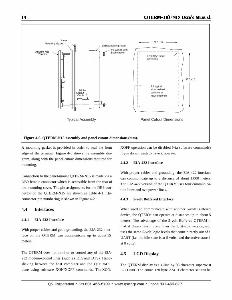
A mounting gasket is provided in order to seal the front
edge of the terminal. Figure 4-6 shows the assembly dia-
gram, along with the panel cutout dimensions required for
mounting.
Connection to the panel-mount QTERM-N15 is made via a
DB9 female connector which is accessible from the rear of
the mounting cover. The pin assignments for the DB9 con-
nector on the QTERM-N15 are shown in Table 4-1. The
connector pin numbering is shown in Figure 4-2.
4.4 Interfaces
4.4.1 EIA-232 Interface
With proper cables and good grounding, the EIA-232 inter-
face on the QTERM can communicate up to about 15
meters.
The QTERM does not monitor or control any of the EIA-
232 modem-control lines (such as RTS and DTS). Hand-
shaking between the host computer and the QTERM i
done using software XON/XOFF commands. The XON/
XOFF operation can be disabled (via software commands)
if you do not wish to have it operate.
4.4.2 EIA-422 Interface
With proper cables and grounding, the EIA-422 interface
can communicate up to a distance of about 1,000 meters.
The EIA-422 version of the QTERM uses four communica-
tion lines and two power lines.
4.4.3 5-volt Buffered Interface
When used to communicate with another 5-volt Buffered
device, the QTERM can operate at distances up to about 5
meters. The advantage of the 5-volt Buffered QTERM i
that it draws less current than the EIA-232 version, and
uses the same 5-volt logic levels that come directly out of a
UART (i.e. the idle state is at 5 volts, and the active state i
at 0 volts).
4.5 LCD Display
The QTERM display is a 4-line by 20-character supertwistLCD unit. The entire 128-byte ASCII character set can be
Figure 4-6. QTERM-N15 assembly and panel cutout dimensions (mm).
Back Mounting Panel
QTERM-N15Terminal
Mounting GasketPanel
#6-32 Nut withLockwasher
DB9OutputCable
145.0 ±1.0
3.1 typical all around (ref. perimeter of mounted panel)
102.8±1.0
3.2 [0.125"] radiuspermissible
Typical Assembly Panel Cutout Dimensions

��������� ������ ������
QSI Corporation • Fax 801-466-8792 • www.qsicorp.com • Phone 801-466-877
displayed. Hosts which transmit 8-bit data can also displayan additional 64 characters including Greek letters, kata-kana characters, non-English alphabetic characters andmath symbols.
Appendix B is a chart which shows what the QTERM doewith every possible 8-bit value it can receive. Note that theASCII portion of the chart (the first 128 characters) is simi-lar, but not identical, to the true ASCII chart shown inAppendix A.
If you ordered the backlight, the software commandshown in Chapter 2 will allow you to turn the backlight onand off. Without the backlight, these commands have noeffect.
4.6 Keypad
The QTERM-J10 is available with an 18-key, 24-key or a40-key keypad. The QTERM-N15 comes with a 12-keykeypad. When each key is pressed, the QTERM will send asingle ASCII character through the serial interface. Somekeys such as F1-F5 and the arrow keys do not have anASCII printable equivalent, so instead they will send a sin-gle lower case letter. Each keypad has a graphic overlaywith labels for each key. Table 4-3 lists the default valueassigned to each key for all three keypad versions.
The keypad utilizes poly-dome keys for long life and tactilefeedback to the operator. Each of the keys sends one or twobytes when pressed.
Software commands allow you to control both key click(on or off) and key repeat (on or off).
4.7 Other Options
4.7.1 Buzzer Option
If you order the buzzer option, the QTERM includes anaudio buzzer which is used for key clicks, and for beepingin response to a “bell” character (^G, 07h).
4.7.2 Regulator Option
The standard QTERM requires a 5-volt regulated powersource. An optional regulator allows the QTERM to beoperated from a 7.5-volt to 24-volt DC source.
4.8 QTERM Specifications
Environmental characteristics of the QTERM-J10 andQTERM-N15 are:
� +0 to +50 °C operating temperature range� -40 to +85 °C storage temperature range� 0 to 95% non-condensing humidity range
Table 4-1. QTERM Pin Assignments.
6-pin Modular Connector
DB9Female
QTERM EIA-232/5-volt Buffered Function
QTERM EIA-422 Function
1 3 receive +receive
2 6 no connection -receive
3 2 transmit +transmit
4 1 no connection -transmit
5 9 power power
6 5 ground ground
Table 4-2. QTERM-J10/N15 Current Consumption.
Version Ireg (mA)
EIA-232 Version 28
EIA-422 Version 25
Add for regulator 6
Add for backlight 60

� ��������� ������ ������
QSI Corporation • Fax 801-466-8792 • www.qsicorp.com • Phone 801-466-877
Table 4-3. Key Assignments.
Key ASCII Char
HexByte
Key ASCIIChar
HexByte
Key ASCIIChar
HexByte
F1 e 65h Q Q 51h 0 0 30h
F2 f 66h R R 52h 1 1 31h
F3 g 67h S S 53h 2 2 32h
F4 h 68h T T 54h 3 3 33h
F5 i 69h U U 55h 4 4 34h
A A 41h V V 56h 5 5 35h
B B 42h W W 57h 6 6 36h
C C 43h X X 58h 7 7 37h
D D 44h Y Y 59h 8 8 38h
E E 45h Z Z 5Ah 9 9 39h
F F 46h / / 2Fh SPACE 20h
G G 47h - - 2Dh ENTER 0Dh
H H 48h + + 2Bh UP a 61h
I I 49h ( ( 28h DOWN b 62h
J J 4Ah ) ) 29h RIGHT c 63h
K K 4Bh # # 23h LEFT d 64h
L L 4Ch * * 2Ah SHIFT N/A
M M 4Dh , , 2Ch BACK 7Fh
N N 4Eh . . 2Eh HOME j 6Ah
O O 4Fh ESC 1Bh CLEAR k 6Bh
P P 50h DEL 7Fh
Table 4-4. Pin Assignments for PC-Style COM Ports.
COM Ports with Male DB25 Connectors COM Ports with Male DB9 Connectors
Pin Function Pin Function
2 PC transmit 1 CD *
3 PC receive 2 PC receive
4 RTS * 3 PC transmit
5 CTS * 4 DTR *
6 DSR * 5 ground
7 ground 6 DSR *
8 CD * 7 RTS *
20 DTR* 8 CTS *
22 RI * 9 RI *
* These lines normally can be left unconnected. Some PCs may require that one or more of them be pulled to 5 volts through a pull-up resistor (about 300 ohms).

QSI Corporation • Fax 801-466-8792 • www.qsicorp.com • Phone 801-466-877
0 1 2 3 4 5 6 7
0
1
2
3
4
5
6
7
NUL
SOH
STX
ETX
EOT
ENQ
ACK
BEL
8
9
A
B
C
D
E
F
BS
HT
LF
VT
FF
CR
SO
SI
DLE
DC1
DC2
DC3
DC4
NAK
SYN
ETB
CAN
EM
SUB
ESC
FS
GS
RS
US
SP
!
"
#
$
%
&
'
(
)
*
+
-
.
/
,
0
1
2
3
4
5
6
7
8
9
:
;
<
=
>
?
@
A
B
C
D
E
F
G
H
I
J
K
L
M
N
O
P
Q
R
S
T
U
V
W
X
Y
Z
[
\
]
^
_
`
a
b
c
d
e
f
g
h
i
j
k
l
m
n
o
p
q
r
s
t
u
v
w
x
y
z
{
|
}
~
DEL
APPENDIX A.
ASCII C HART
NUL = blankSOH = start of headerSTX = start of textETX = end of textEOT = end of transmissionENQ = enquiryACK = acknowledgeBEL = bell
BS = backspaceHT = horizontal tabLF = line feedVT = vertical tabFF = form feedCR = carriage returnSO = shift outSI = shift inSP = space
DLE = data link escapeDC1 = device control 1 (XON)DC2 = device control 2DC3 = device control 3 (XOFF)DC4 = device control 4
NAK = negative acknowledgeSYN = synchronizationETB = end of text blockCAN = cancel
EM = end of mediumSUB = substituteESC = escape
FS = file separatorGS = group separatorRS = record separatorUS = unit separator
DEL = delete/rubout

� ��������� ������ ������
QSI Corporation • Fax 801-466-8792 • www.qsicorp.com • Phone 801-466-877

QSI Corporation • Fax 801-466-8792 • www.qsicorp.com • Phone 801-466-877
APPENDIX B.
QTERM C HARACTER CHART
The chart on the next page shows how the QTERMresponds to each of the 256 possible values of characterwhich it can receive.
Where a dot pattern is shown, sending the correspondingcode will cause the QTERM to display the dot pattern at thecurrent cursor location.
Numbers in circles refer to these notes
�These bytes are always ignored.
�This is a space character.
Other notations in the chart are:
BEL bell (beep) commandBS backspaceHT horizontal tabLF line feedCR carriage returnXON XON characterXOFF XOFF characterESC escape characterDEL delete character
Note that, although the left half of this chart is similar to theASCII chart in Appendix A, there are differences.

� ��������� ������ ������
QSI Corporation • Fax 801-466-8792 • www.qsicorp.com • Phone 801-466-877
Leas
t Sig
nific
ant D
igit
(hex
)
HT
CR
F
E
D
C
B
A
9
8
6
7
5
LF
LF
LF
BS
Most Significant Digit (hex)
3
4
2
1
0
30 1 2 4 5 6 A7 8 9 B C D FE
1 1
1
1 1
1
1 1
11
1 1
1
1
1
1
1
1
11
1 1 1
1
1
1
1 1
11
1 1
11
1 1
11
1 1
11
1 1
11
1 1
112 2
2
2
2
2
2
( Notes � and � are on the previous page.)

QSI Corporation • Fax 801-466-8792 • www.qsicorp.com • Phone 801-466-877
APPENDIX C.
QTERM C OMMAND SUMMARY
This appendix is an abbreviated summary of all of theavailable QTERM software commands. More detaileddescriptions of the commands are in Chapter 2. If a comand parameter is out of the valid range, the QTERMignores the entire command.
Note that the timing shown for the execution of the variouscommands is only approximate. Many factors can affect theexecution time, so it is impossible to give exact figures.
Command StringTiming
(ms)Notes & Parameters
display character 0.735
typicalmax
Bell (^G) 07H 0.6
Backspace (^H) 08H 0.8
Horizontal Tab (^I) 09H 0.8 1.1 ms worst case
Line Feed (^J 0AH 0.8 up to 35 ms if auto scroll is on
Vertical Tab (^K) 0BH same as line feed
Form Feed (^L) 0CH same as line feed
Carriage Return (^M) 0DH 0.8 up to 35 ms if auto scroll is on
XON (^Q) 11H 0.4
XOFF (^S) 13H 0.4
Delete 7FH 1.2
Cursor Up ESC A 0.8
Cursor Down ESC B 0.8
Cursor Right ESC C 0.8
Cursor Left ESC D 0.8
Clear Screen ESC E 4.4
Cursor Home ESC H 3.7
Set Cursor Position ESC # * 1.5 # = @ to C for row 0 to 3* = @ to S for column 0 to 19
�� ��������� ������ ������
QSI Corporation • Fax 801-466-8792 • www.qsicorp.com • Phone 801-466-877
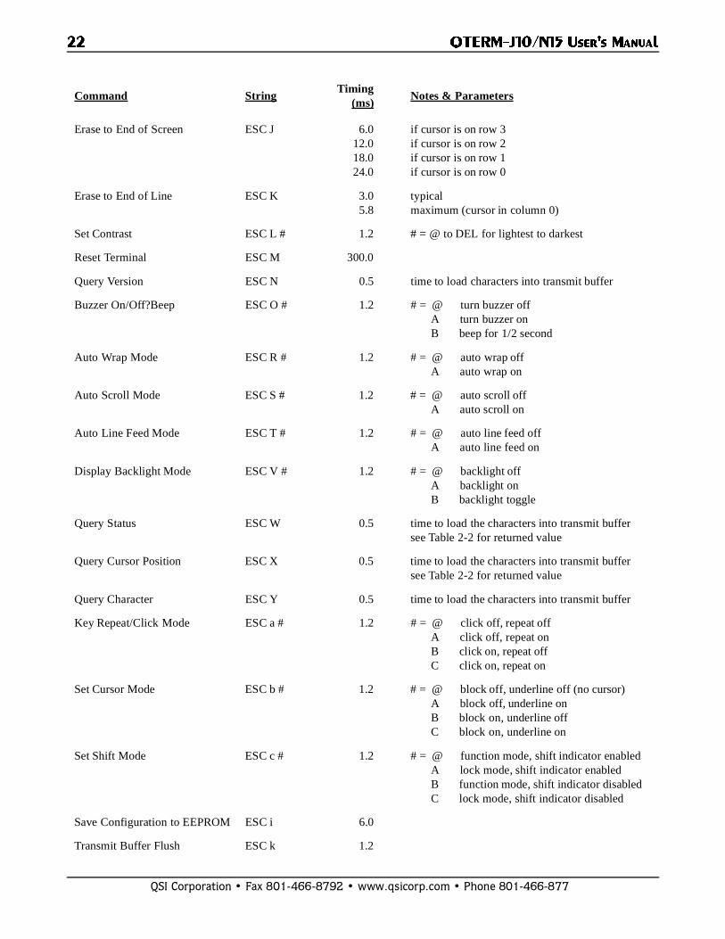
Erase to End of Screen ESC J 6.012.018.024.0
if cursor is on row 3if cursor is on row 2if cursor is on row 1if cursor is on row 0
Erase to End of Line ESC K 3.05.8
typicalmaximum (cursor in column 0)
Set Contrast ESC L # 1.2 # = @ to DEL for lightest to darkest
Reset Terminal ESC M 300.0
Query Version ESC N 0.5 time to load characters into transmit buffer
Buzzer On/Off?Beep ESC O # 1.2 # = @ turn buzzer off A turn buzzer on B beep for 1/2 second
Auto Wrap Mode ESC R # 1.2 # = @ auto wrap off A auto wrap on
Auto Scroll Mode ESC S # 1.2 # = @ auto scroll off A auto scroll on
Auto Line Feed Mode ESC T # 1.2 # = @ auto line feed off A auto line feed on
Display Backlight Mode ESC V # 1.2 # = @ backlight off A backlight on B backlight toggle
Query Status ESC W 0.5 time to load the characters into transmit buffer see Table 2-2 for returned value
Query Cursor Position ESC X 0.5 time to load the characters into transmit buffer see Table 2-2 for returned value
Query Character ESC Y 0.5 time to load the characters into transmit buffer
Key Repeat/Click Mode ESC a # 1.2 # = @ click off, repeat off A click off, repeat on B click on, repeat off C click on, repeat on
Set Cursor Mode ESC b # 1.2 # = @ block off, underline off (no cursor) A block off, underline on B block on, underline off C block on, underline on
Set Shift Mode ESC c # 1.2 # = @ function mode, shift indicator enabled A lock mode, shift indicator enabled B function mode, shift indicator disabled C lock mode, shift indicator disabled
Save Configuration to EEPROM ESC i 6.0
Transmit Buffer Flush ESC k 1.2
Command StringTiming
(ms)Notes & Parameters

��������� ������ ������ ��
QSI Corporation • Fax 801-466-8792 • www.qsicorp.com • Phone 801-466-877
XON/XOFF Mode ESC 1 # 1.2 # = @ disable XON/XOFF operation A enable XON/XOFF operation
User Area Read/Write ESC m # depends onbaud rate
Restore Default Parameters ESC r 3.0
Verify MID Code ESC u # * 2.0 # and * are the bytes you want to compare
Power-On Setup Mode ESC x # 1.2 # = @ power-on setup fully enabled A only contrast adjustment allowed B power-on setup fully disabled
Command StringTiming
(ms)Notes & Parameters

�� ��������� ������ ������
QSI Corporation • Fax 801-466-8792 • www.qsicorp.com • Phone 801-466-877