Embed Size (px)
Citation preview
QRPi – A Raspberry Pi QRP TX Shield Design
Zoltán Dóczi, HA7DCDBudapest, Hungaryrfsparkling.com
Abstract
"Be Smart, Not Strong" this should be the self explaining phrase of the QRP term in amateur radio. Low poweroperation is always more difcult than using hundreds or thousands of wats RF power. But the smile on yourface afer the frst thousands miles long QSO, using portions of one wat is worth the challenge! QRP enthusiastsinstead of spending time and money on increasing power capabilities of its station prefer a smarter way: to learnabout new modulations and coding techniques and applying them in everyday HAM operation practice.
Nowadays one of the most impressive QRP mode is Joe Taylor, K1JT's [8] WSPR [9] (pronounced "whisper").WSPR stands for "Weak Signal Propagation Reporter". Programs writen for WSPR mode designed for sendingand receiving low-power transmissions to test propagation paths on the MF and HF and recently UHF bands.Users with internet access can watch results in real time at wsprnet.org
The QRPi board (or shield as referred by the community today) is an inexpensive way turning a Raspberry Pisingle-board computer into a QRP transmiter.
Keywords: QRP, RPi, SDR, WSPR, open-source
Introduction
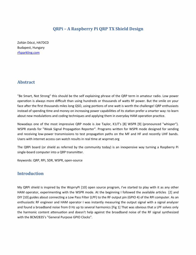
My QRPi shield is inspired by the WsprryPi [10] open source program, I've started to play with it as any otherHAM operator, experimenting with the WSPR mode. At the beginning I followed the available articles [2] andDIY [10] guides about connecting a Low Pass Filter (LPF) to the RF output pin (GPIO 4) of the RPi computer. As anenthusiastic RF engineer and HAM operator I was instantly measuring the output signal with a signal analyzerand found a broadband noise from 0 Hz up to several harmonics [Fig 1] That was obvious that a LPF solves onlythe harmonic content atenuation and doesn't help against the broadband noise of the RF signal synthesizedwith the BCM2835’s "General Purpose GPIO Clocks".
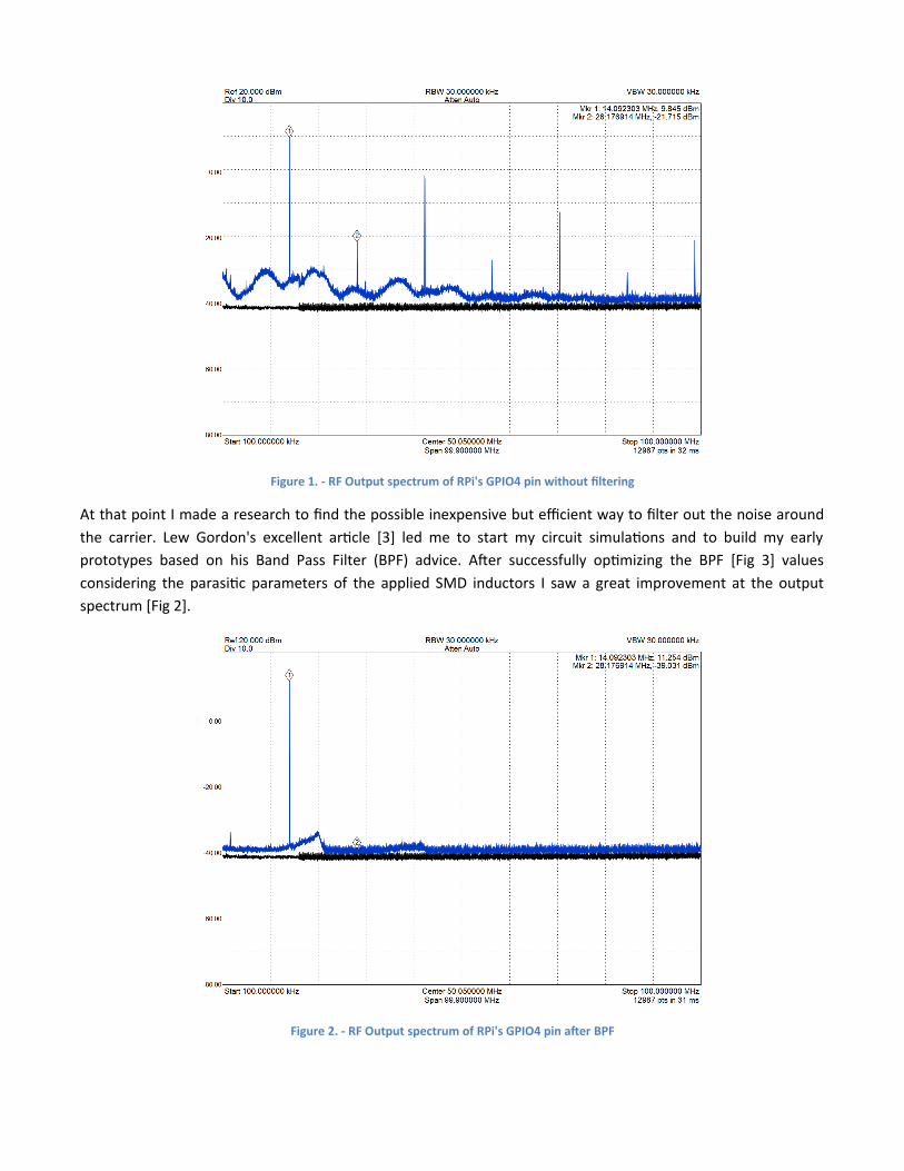
Figure 1. - RF Output spectrum of RPi's GPIO4 pin without fitering
At that point I made a research to fnd the possible inexpensive but efcient way to flter out the noise aroundthe carrier. Lew Gordon's excellent article [3] led me to start my circuit simulations and to build my earlyprototypes based on his Band Pass Filter (BPF) advice. Afer successfully optimizing the BPF [Fig 3] valuesconsidering the parasitic parameters of the applied SMD inductors I saw a great improvement at the outputspectrum [Fig 2].
Figure 2. - RF Output spectrum of RPi's GPIO4 pin afer BPF
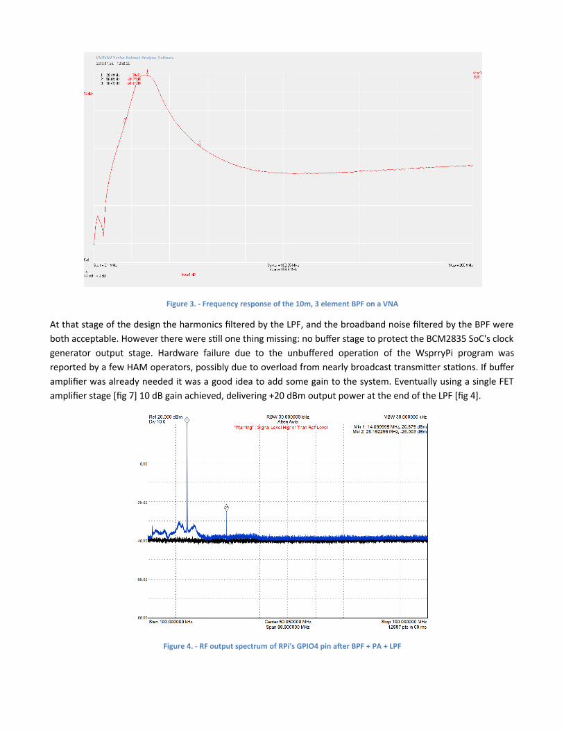
Figure 3. - Frequency response of the 10m, 3 eiement BPF on a VNA
At that stage of the design the harmonics fltered by the LPF, and the broadband noise fltered by the BPF wereboth acceptable. However there were still one thing missing: no bufer stage to protect the BCM2835 SoC's clockgenerator output stage. Hardware failure due to the unbufered operation of the WsprryPi program wasreported by a few HAM operators, possibly due to overload from nearly broadcast transmiter stations. If buferamplifer was already needed it was a good idea to add some gain to the system. Eventually using a single FETamplifer stage [fg 7] 10 dB gain achieved, delivering 220 dBm output power at the end of the LPF [fg 4].
Figure 4. - RF output spectrum of RPi's GPIO4 pin afer BPF + PA + LPF
For ESD and static discharge protection an ESD suppressor diode was added to the antenna terminal of the circuit.
I've targeted the absolutely smallest and most compact form factor. I've seen several RPi HAM accessories whichwere too "bulky" in my point of view. Using large external PCBs with long cables atached to the RPi it's destroythe true value of the card sized computer: small, mobile and fexible.
As I wanted to give an inexpensive QRP shield for the HAM and RPi community, mass production capability(SMD parts) and cheap component selection (eg. no SMA connector) was mandatory from the initial planningphase.
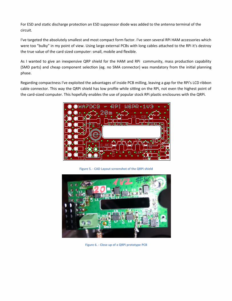
Regarding compactness I've exploited the advantages of inside PCB milling, leaving a gap for the RPi's LCD ribboncable connector. This way the QRPi shield has low profle while sitng on the RPi, not even the highest point ofthe card-sized computer. This hopefully enables the use of popular stock RPi plastic enclosures with the QRPi.
Figure 5. - CAD Layout screenshot of the QRPi shieid
Figure 6. - Ciose up of a QRPi prototype PCB
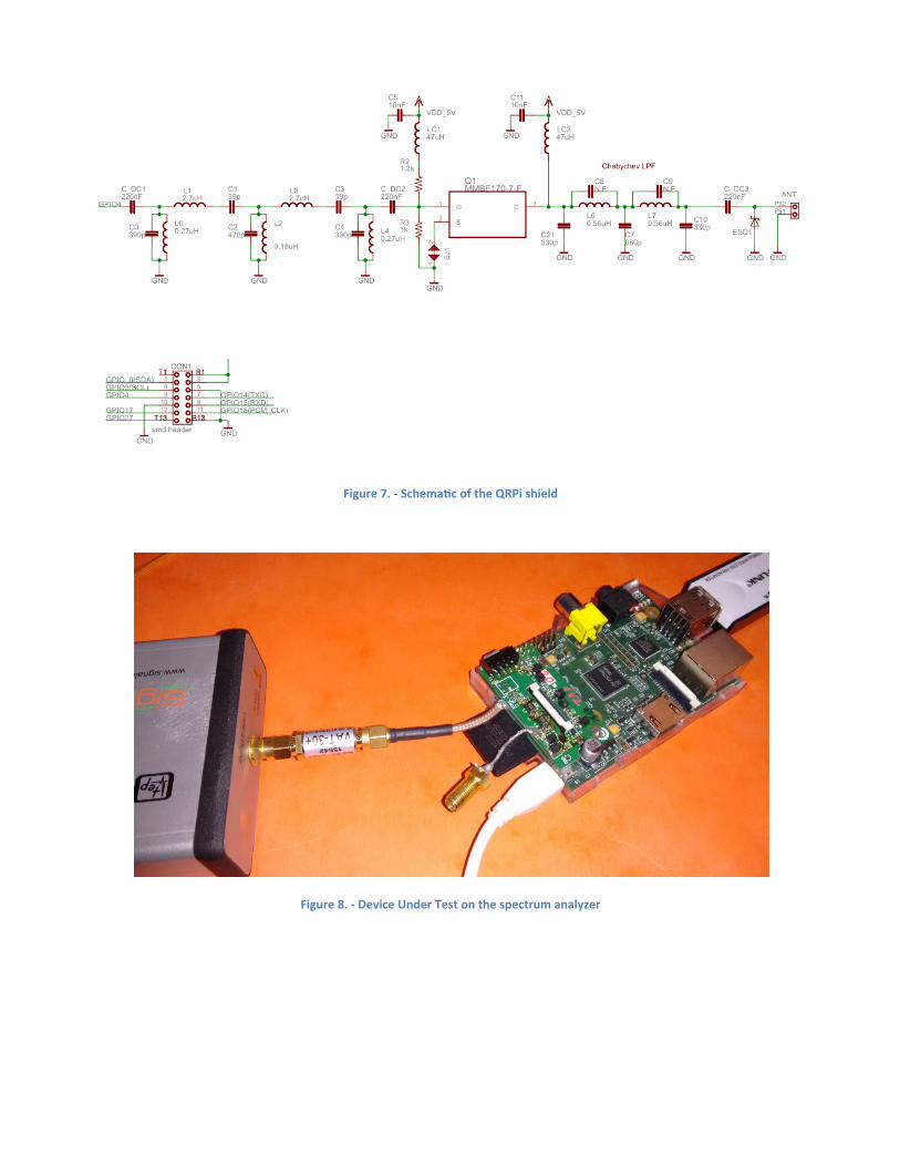
Figure 7. - Schematc of the QRPi shieid
Figure 8. - Device Under Test on the spectrum anaiyzer
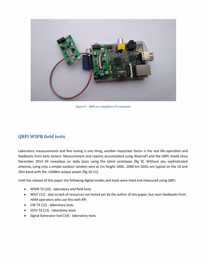
Figure 9. - QRPi on a Raspberry Pi computer
QRPi WSPR field tests
Laboratory measurements and fne tuning is one thing, another important factor is the real life operation andfeedbacks from beta testers. Measurement and reports accumulated using WsprryPi and the QRPi shield sinceDecember 2014 till nowadays on daily basis using the latest prototype [fg 9]. Without any sophisticatedantenna, using only a simple outdoor random wire at 2m height 1000...2000 km QSOs are typical on the 10 and20m band with the 220dBm output power [fg 10-11].
Until the release of this paper the following digital modes and tools were tried and measured using QRPi:
WSPR TX [10] - laboratory and feld tests WSJT [11] - due to lack of resources not tested yet by the author of this paper, but seen feedbacks from
HAM operators who use this with RPi CW TX [12] - laboratory tests SSTV TX [13] - laboratory tests Signal Generator tool [14] - laboratory tests
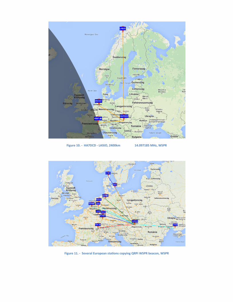
Figure 10. - HA7DCD - LA9JO, 2400km 14.097185 MHz, WSPR
Figure 11. - Severai European statons copying QRPi WSPR beacon, WSPR
Possible further developments
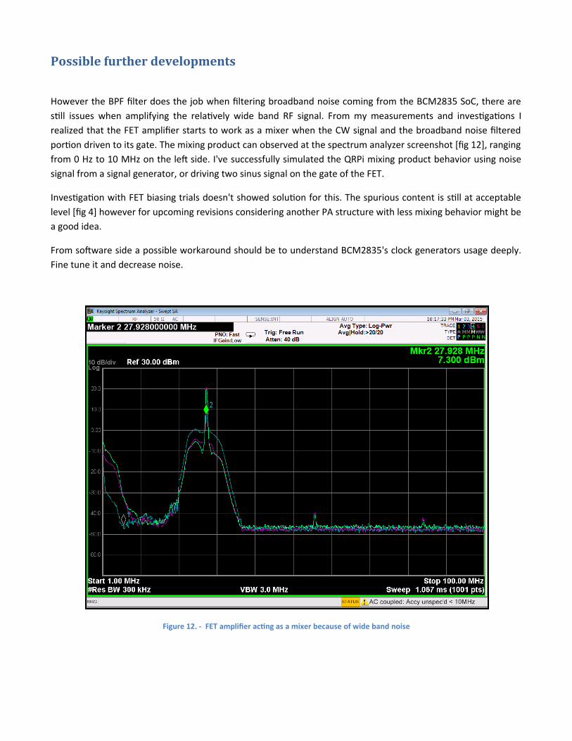
However the BPF flter does the job when fltering broadband noise coming from the BCM2835 SoC, there arestill issues when amplifying the relatively wide band RF signal. From my measurements and investigations Irealized that the FET amplifer starts to work as a mixer when the CW signal and the broadband noise flteredportion driven to its gate. The mixing product can observed at the spectrum analyzer screenshot [fg 12], rangingfrom 0 Hz to 10 MHz on the lef side. I've successfully simulated the QRPi mixing product behavior using noisesignal from a signal generator, or driving two sinus signal on the gate of the FET.
Investigation with FET biasing trials doesn't showed solution for this. The spurious content is still at acceptablelevel [fg 4] however for upcoming revisions considering another PA structure with less mixing behavior might bea good idea.
From sofware side a possible workaround should be to understand BCM2835's clock generators usage deeply.Fine tune it and decrease noise.
Figure 12. - FET ampiifer actng as a mixer because of wide band noise
I would like to say thanks for the kind help of:
Steven Bible - N7HPRAndris Retzler - HA7ILMHackerspace Budapest and András Veres-Szentkirályi "dnet" - HA5KBP Tucson Amateur Packet Radio CorpHA5KFU Schönherz Amateur Radio Club
Reference List
1. QRP defnition - htps://en.wikipedia.org/wiki/QRP_operation2. TUTORIAL: TRANSMITTER (PA) OUTPUT FILTERS by Paul Harden, NA5N
htp://www.aoc.nrao.edu/ppharden/hobby/_lpf_pa.pdf3. Band Pass Filters for HF Transceivers by Lew Gordon, K4VX
htp://www.arrl.org/fles/fle/Technology/tis/info/pdf/8809017.pdf4. Raspberry Pi website - htps://www.raspberrypi.org5. Raspberry Pi Low Level Peripherals - htp://elinux.org/RPi_Low-level_peripherals6. Raspberry Pi SoC, Broadcom BCM2835 - htp://www.raspberry-projects.com/pi/pi-hardware/bcm28357. BCM2835 datasheet - htp://www.farnell.com/datasheets/1521578.pdf8. K1JT website - htp://physics.princeton.edu/pulsar/K1JT/9. Weak Signal Propagation Reporter Network - htp://wsprnet.org
Raspberry Pi transmiter programs working with QRPI TX shield:
10. WSPR - htps://github.com/JamesP6000/WsprryPi11. WSJT - htp://hajos-kontrapunkte.blogspot.hu/2014/04/silent-whisper-jt9-on-cubie-truck.html12. CW - htps://github.com/JamesP6000/PiCW13. SSTV - htps://github.com/JennyList/LanguageSpy/tree/master/RaspberryPi/rf/sstv14. Signal Generator - htps://github.com/JennyList/LanguageSpy/tree/master/RaspberryPi/rf/freq_pi
15. HA5KFU Radio Club - htp://ha5kfu.sch.bme.hu16. Hackerspace Budapest - htp://hsbp.org/