Embed Size (px)
Citation preview
QoS TESTING IN A LIVE PRIVATE IP MPLS
NETWORK WITH CoS IMPLEMENTED
Živko Bojović1, Emil Šećerov2 and Vlado Delić2
1 Telekom Srbija, Takovska 2, 11000 Beograd, Serbia,
2 Faculty of Technical Sciences, Trg D. Obradovića 6,
21000 Novi Sad, Serbia {secerov, tlk_delic}@uns.ac.rs
Abstract. This paper describes a testing conducted on a private IP/MPLS network of a Telecom operator during service introduction. We have applied DiffServ and E-LSP policies for bandwidth allocation for predefined classes of service (voice, video, data and VPN). We used a traffic generator to create the worst possible situations during the testing, and measured QoS for individual services. UML considerations about NGN structure and packet networks traffic testing are also presented using the deployment, class and state diagrams. Testing results are given in tabular and graphical forms, and the conclusions derived will be subsequently used as a basis for defining the stochastic traffic generator/simulator.
Keywords: network testing, IP/MPLS, DiffServ, traffic generator, worst case, UML.
1. Introduction
Development of telecommunication market and technologies caused transformation of networks specialized for dedicated service into multiservice networks (voice, video, data, L2 and L3 virtual private networks-VPNs) across the common infrastructure and unique service handling. Decisive influence to this transformation had the implementation of new technologies in the networks of telecommunication operators (see Fig. 1) and adoption of internet protocol (IP) core in next generation networks (NGN). Real-time network services, e.g. telephony, video or multimedia service,
which will prevail in the near future, are very dependent on variation of quality of service (QoS) parameters (delay, jitter and packet loss). The NGN convergence toward an unique network architecture offers capability of a flexible, on-demand and dynamic, bandwidth allocation for specific service
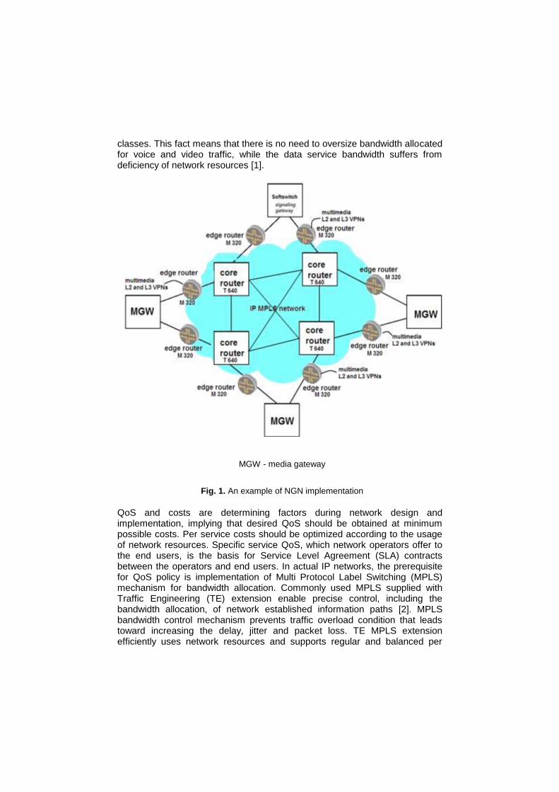
classes. This fact means that there is no need to oversize bandwidth allocated for voice and video traffic, while the data service bandwidth suffers from deficiency of network resources [1].
MGW - media gateway
Fig. 1. An example of NGN implementation
QoS and costs are determining factors during network design and implementation, implying that desired QoS should be obtained at minimum possible costs. Per service costs should be optimized according to the usage of network resources. Specific service QoS, which network operators offer to the end users, is the basis for Service Level Agreement (SLA) contracts between the operators and end users. In actual IP networks, the prerequisite for QoS policy is implementation of Multi Protocol Label Switching (MPLS) mechanism for bandwidth allocation. Commonly used MPLS supplied with Traffic Engineering (TE) extension enable precise control, including the bandwidth allocation, of network established information paths [2]. MPLS bandwidth control mechanism prevents traffic overload condition that leads toward increasing the delay, jitter and packet loss. TE MPLS extension efficiently uses network resources and supports regular and balanced per
service bandwidth allocation. Efficient, on demand and dynamic, bandwidth usage anticipates and prevents from network overload caused by burst nature of NGN traffic. Finally, it also can guarantee QoS agreed by SLA. However, standard MPLS-TE does not reserve per service class bandwidth.
Bandwidth allocation policy is used for aggregated services traffic flows. Since that network operators commonly use IETF (Internet Engineering Task Force) Differentiated Service (DiffServ) standard that supports much wider Class of Services (CoS) than MPLS-TE [3]. MPLS DiffServ–TE combine advantages of both MPLS extensions (DiffServ and TE) to achieve strict QoS guaranties while optimizing the network resources. MPLS DiffServ-TE aware the network with CoS configuration enabling per service class resource reservation, service granularity for end user and QoS guaranties defined in SLA. Today, Class of Service support has become an indispensable function in
many of the large service provider networks because of the competitive nature of the Internet and the diversity in customer needs. CoS support in traditional IP routed cores has been provided by a variety of queuing and scheduling mechanisms. This paper presents some experience in testing CoS translation in IP/MPLS based packet network. Effects of relative and fixed bandwidth allocation for different CoS in the bursty traffic conditions are discussed based on experimental results. Paper is organized as follows. Section 2 gives short overview of related work in the area of telecommunication traffic and sources for the proposed UML (Unified Modeling Language) view of the network. Section 3 is the continuation of the introduction and presents an overview UML specification of NGN. Section 4 outlines some of the techniques put forth by the IP network to MPLS CoS mapping over arbitrary layer-2 technology. Sections 5 describe the traffic classes in the network that is the subject of the experiment. Section 6 describes the test environment, the tools used in conducting the experiments and shows the results of experiments. It also gives the UML view of test network topology and state diagram for statistical MUX that is important for understanding the dynamics of packet networks scheduling process. Section 7 is the conclusion with some final comments.
2. Related Work
The first papers in this field of IP communication were written with the aim to improve the knowledge of MPLS concepts, installation, migration, operation, inspection and troubleshooting in accordance with applicable RFC documents [1], [2]. The effort was made to make a general review of MPLS and to explain its functioning in telecommunication networks. In other words, the intention was to point out all aspects of implementation, integration and installation of MPLS infrastructure in the networks of telecom operators. The next group of papers was based on implementation of Quality of Service mechanisms as a critical element to solving the problems of handling the increasing volume and disparate types of traffic seen on today's public and private networks [3].
Whenever a mission critical application - whether voice, video, or data - is being delivered over a network, Quality of Service traffic shaping and policing can assist network managers in maintaining the best network performance and good-put for applications during periods of network congestion [7]. As far as we know in this moment there are no available papers or other
sources of knowledge that propose UML view for the telecommunication networks structure and behavior. According to this we are trying to initiate work in this ICT( Information and Communication Technologies) convergence field and the main UML sources for this paper were [4], [5] and [6]. QoS offers the following core principles: Classification and Marking, Policing,
Queuing and Dropping. Class of Service is Quality of Service method used to manage the network during congestion as implemented in Junos (Juniper Operating System) software [8]. It allows the network administrator to identify the order of priority that the incoming traffic should be processed for transmission when the switch or network is congested. As an example, a weighted round robin (WRR) method prevents head-of-line blocking. Juniper routers, with implemented Junos, are reliable, high-performance network operating system for routing, switching and security features [9]. Starting from the previously mentioned, the desire of the authors was that, in the vibrant MPLS network with a specific configuration and implemented in the Junos software within the JUNIPER routers, examine the behavior of these networks in some critical cases. In that sense, we made the test scenarios whose contents and results will be listed below the text block.
3. UML Specification of NGN
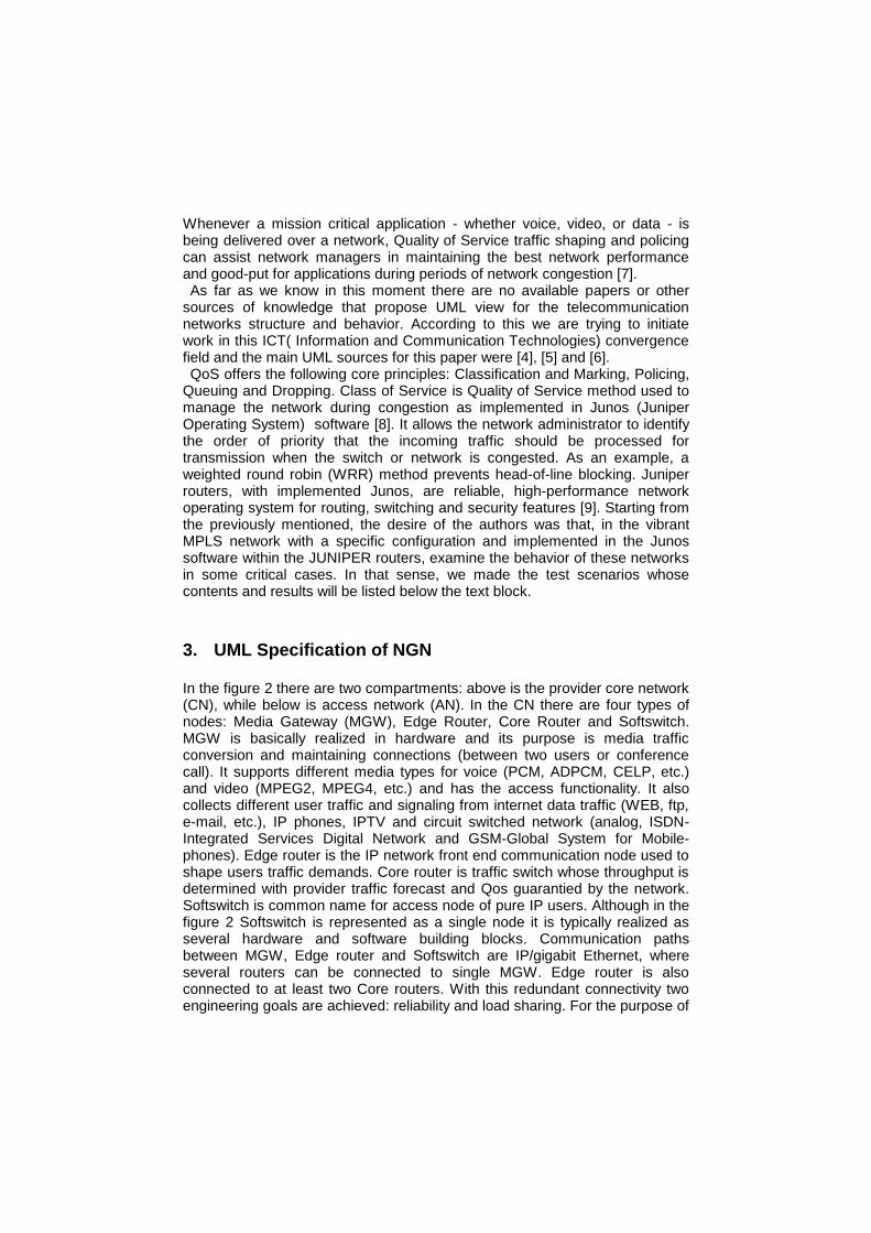
In the figure 2 there are two compartments: above is the provider core network (CN), while below is access network (AN). In the CN there are four types of nodes: Media Gateway (MGW), Edge Router, Core Router and Softswitch. MGW is basically realized in hardware and its purpose is media traffic conversion and maintaining connections (between two users or conference call). It supports different media types for voice (PCM, ADPCM, CELP, etc.) and video (MPEG2, MPEG4, etc.) and has the access functionality. It also collects different user traffic and signaling from internet data traffic (WEB, ftp, e-mail, etc.), IP phones, IPTV and circuit switched network (analog, ISDN-Integrated Services Digital Network and GSM-Global System for Mobile-phones). Edge router is the IP network front end communication node used to shape users traffic demands. Core router is traffic switch whose throughput is determined with provider traffic forecast and Qos guarantied by the network. Softswitch is common name for access node of pure IP users. Although in the figure 2 Softswitch is represented as a single node it is typically realized as several hardware and software building blocks. Communication paths between MGW, Edge router and Softswitch are IP/gigabit Ethernet, where several routers can be connected to single MGW. Edge router is also connected to at least two Core routers. With this redundant connectivity two engineering goals are achieved: reliability and load sharing. For the purpose of
maximal reliability core routers are fully connected, that is marked with cardinality “all” in the figure 2. Access network supports all of the today available user devices, but it is expected that IP access will prevail in the near future.
deployment IP/MPLS Network
IAD SDH
«device»
MGW
IAD SDH
«device»
Core Router
T640
«device»
Edge Router
M320
SDH
«device»
TDM Exchange
SDH
«device»
Analog phone
«device»
ISDN access
«device»
GSM phone
IP/MPLS/ge
network
Access
network
Switched
circuit network
IP access
IP Access
«device»
Softswitch
IP Access
IAD«device»
:IP phone/IPTV/dataIAD
IAD«device»
:IP phone/IPTV/data IAD
1
«TDM»
11
IPphone/IPTV/data
«ADSL»
0..*
1..*
«IP/ge» 1..*
0..*
IPphone/IPTV/data
«ADSL»
1
1..*
«air interface»
1
1..*
«copper wire»
1
1..*
«copper wire»
1
all
«MPLS/IP/ge»
all
1..* «MPLS/IP/ge» 2..*
1
«IP/ge»
1..*
Fig. 2. Deployment diagram of the considered IP/MPLS network topology
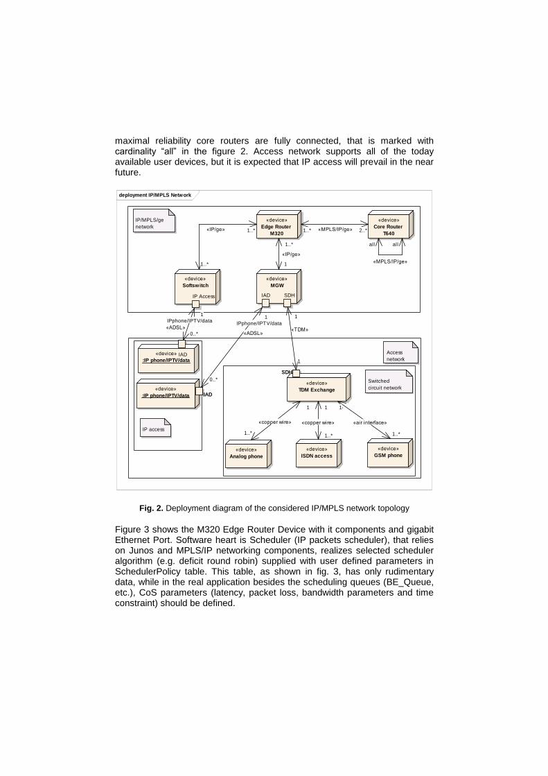
Figure 3 shows the M320 Edge Router Device with it components and gigabit Ethernet Port. Software heart is Scheduler (IP packets scheduler), that relies on Junos and MPLS/IP networking components, realizes selected scheduler algorithm (e.g. deficit round robin) supplied with user defined parameters in SchedulerPolicy table. This table, as shown in fig. 3, has only rudimentary data, while in the real application besides the scheduling queues (BE_Queue, etc.), CoS parameters (latency, packet loss, bandwidth parameters and time constraint) should be defined.
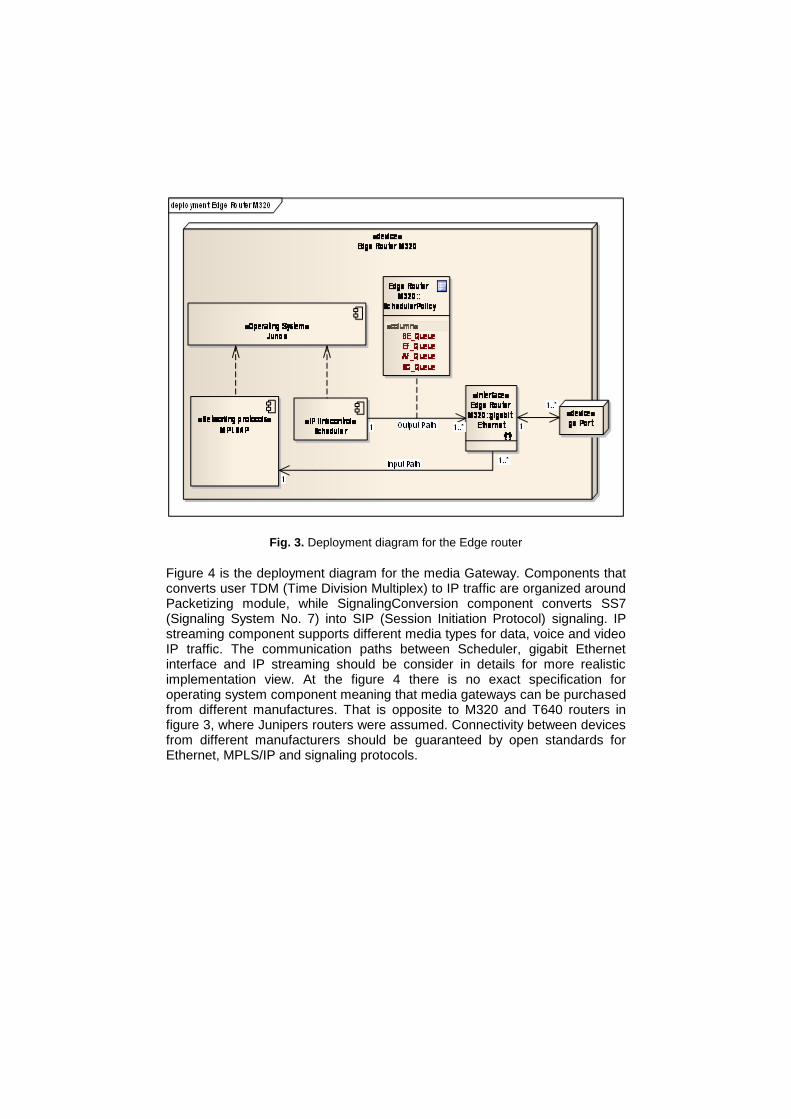
Fig. 3. Deployment diagram for the Edge router
Figure 4 is the deployment diagram for the media Gateway. Components that converts user TDM (Time Division Multiplex) to IP traffic are organized around Packetizing module, while SignalingConversion component converts SS7 (Signaling System No. 7) into SIP (Session Initiation Protocol) signaling. IP streaming component supports different media types for data, voice and video IP traffic. The communication paths between Scheduler, gigabit Ethernet interface and IP streaming should be consider in details for more realistic implementation view. At the figure 4 there is no exact specification for operating system component meaning that media gateways can be purchased from different manufactures. That is opposite to M320 and T640 routers in figure 3, where Junipers routers were assumed. Connectivity between devices from different manufacturers should be guaranteed by open standards for Ethernet, MPLS/IP and signaling protocols.
deployment Media Gateway
«device»
MGW
«Operating System»
UDP SCTP
«Networking protocols»
:MPLS/IP
UDP SCTP
«executable»
:Packetizing
«interface»
:TDM_Data
«executable»
:SIP Signalling
«executable»
:SS7 Signalling
«device»
:TDM Port
«executable»
:SignalingConv ersion
:IP Streaming
«device»
ge Port
PCM data
SS7 link
Input Path
«SIP Signaling»
Output Path
«SIP Signaling»
User Data
«vice,video,data»
Fig. 4. Deployment diagram for the media gateway
4. CoS Policy Implementation
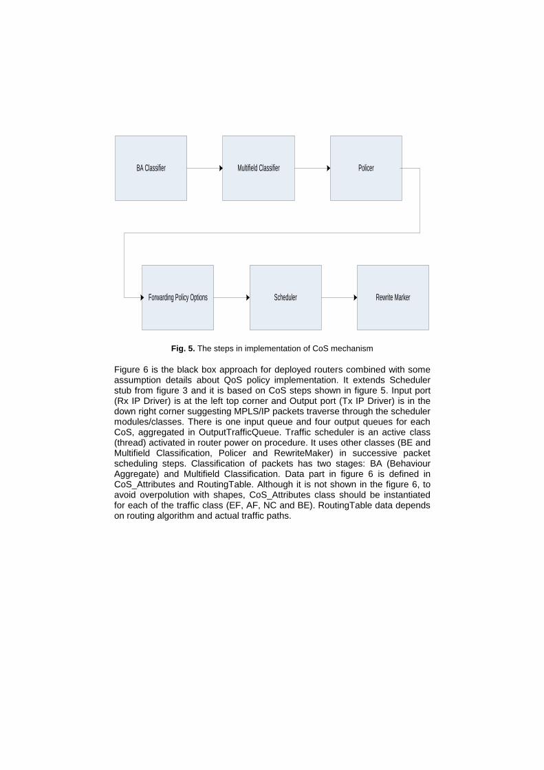
One of the basic trends in communications is network and service convergence, i.e. a unique network architecture that simultaneously offers different types of services: voice, video, data, VPNs and others. The different types of service need different QoS requirements considering delay, jitter, and packet loss. In order to provide quality of service from end to end, providers usually apply model based upon IETF DiffServ standard, since it supports a vast number of classes of service [7]. For this reason, the CoS mechanisms are implemented into routers, implying the following steps (Fig. 5):
packet classification (Behavior Aggregate and Multifield) at input interface;
policing application for the traffic flow (Policer);
policing application for the traffic transmission according to the CoS attributes (Forwarding Class Policer);
scheduling the transmission at the output interface (Scheduler);
marking the bits at the output interface (Rewrite Marker).
BA Classifier
SchedulerForwarding Policy Options
PolicerMultifield Classifier
Rewrite Marker
Fig. 5. The steps in implementation of CoS mechanism
Figure 6 is the black box approach for deployed routers combined with some assumption details about QoS policy implementation. It extends Scheduler stub from figure 3 and it is based on CoS steps shown in figure 5. Input port (Rx IP Driver) is at the left top corner and Output port (Tx IP Driver) is in the down right corner suggesting MPLS/IP packets traverse through the scheduler modules/classes. There is one input queue and four output queues for each CoS, aggregated in OutputTrafficQueue. Traffic scheduler is an active class (thread) activated in router power on procedure. It uses other classes (BE and Multifield Classification, Policer and RewriteMaker) in successive packet scheduling steps. Classification of packets has two stages: BA (Behaviour Aggregate) and Multifield Classification. Data part in figure 6 is defined in CoS_Attributes and RoutingTable. Although it is not shown in the figure 6, to avoid overpolution with shapes, CoS_Attributes class should be instantiated for each of the traffic class (EF, AF, NC and BE). RoutingTable data depends on routing algorithm and actual traffic paths.
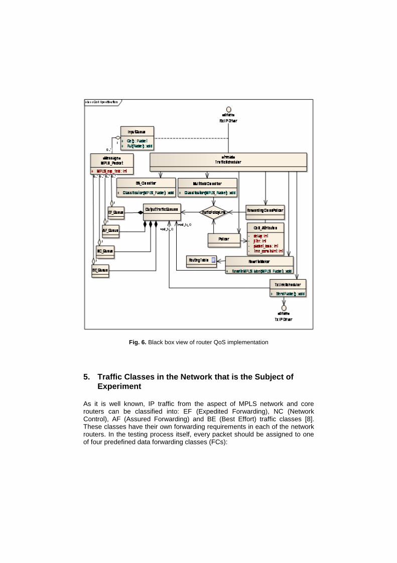
Fig. 6. Black box view of router QoS implementation
5. Traffic Classes in the Network that is the Subject of
Experiment
As it is well known, IP traffic from the aspect of MPLS network and core routers can be classified into: EF (Expedited Forwarding), NC (Network Control), AF (Assured Forwarding) and BE (Best Effort) traffic classes [8]. These classes have their own forwarding requirements in each of the network routers. In the testing process itself, every packet should be assigned to one of four predefined data forwarding classes (FCs):
EF class provides the lowest values of packet loss, delay and jitter. It also secures the bandwidth for services in this class, end to end. Voice and video packets, with real-time traffic requirements, belong to this class.
AF class allows the definition of group values for certain traffic subclasses, including three different packet rejection possibilities. Traffic packets from layer-2 and layer-3 VPNs belong to this service class.
BE class does not provide reliable types of service profiles; it usually applies a more aggressive packet rejection profile, e.g. random early detection (RED). It encompasses data packets.
NC class usually has a high priority since it supports network control protocols operation.
Each of the listed classes is suitable for a specific service category. For the transfer of traffic sensitive to delays, jitters and losses, such as voice and video transmission in real time, it is necessary to assign EF service class. For common Internet traffic, BE class offers a satisfactory service, whereas transmission of higher priority traffic should be assigned the AF class. NC service category should be chosen for the exchange of packets necessary for the operation of routing protocol in the network. There are several different methods of packet classification, i.e. assigning packets to different service classes based on the value contained in the CoS fields or based on the conditions examining the values of other fields within the packet header. In our case the router shall not undergo any configuration adjustments, but rather a BA classifier shall be implemented in the traffic generator. The considered network contains the Juniper Networks routers (M320 and M10i in Fig. 7) configured to support up to 4 FCs (Forwarding Classes) [9]. The FCs configuration with Junos software is listed at listing 1:
[edit class-of-service forwarding-class]
user@RouterA# show
queue 0 BE;
queue 1 EF;
queue 2 AF;
queue 3 NC;
Listing 1. Network routers scheduling configuration
It can be seen that traffic is grouped into four scheduling queues that support FSs explained earlier.
6. QoS/CoS Test Environment
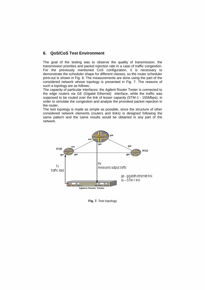
The goal of the testing was to observe the quality of transmission, the transmission priorities and packet rejection rate in a case of traffic congestion. For the previously mentioned CoS configuration, it is necessary to demonstrate the scheduler shape for different classes, so the router scheduler print-out is shown in Fig. 8. The measurements are done using the part of the considered network whose topology is presented in Fig. 7. The reasons of such a topology are as follows: The capacity of particular interfaces: the Agilent Router Tester is connected to the edge routers via GE (Gigabit Ethernet) interface, while the traffic was supposed to be routed over the link of lesser capacity (STM-1 - 155Mbps), in order to simulate the congestion and analyze the provoked packet rejection in the router, The test topology is made as simple as possible, since the structure of other considered network elements (routers and links) is designed following the same pattern and the same results would be obtained in any part of the network.
Fig. 7. Test topology
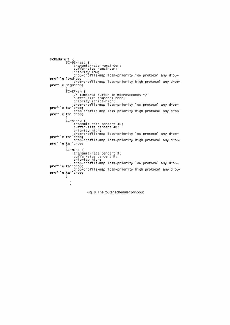
Fig. 8. The router scheduler print-out
6.1. UML Specification of test network
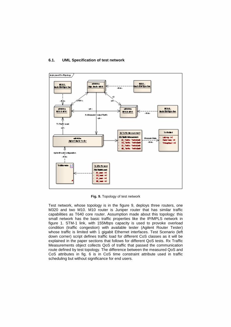
Fig. 9. Topology of test network
Test network, whose topology is in the figure 9, deploys three routers, one M320 and two M10. M10 router is Juniper router that has similar traffic capabilities as T640 core router. Assumption made about this topology: this small network has the basic traffic properties like the IP/MPLS network in figure 1. STM-1 link, with 155Mbps capacity is used to provoke overload condition (traffic congestion) with available tester (Agilent Router Tester) whose traffic is limited with 1 gigabit Ethernet interfaces. Test Scenario (left down corner) script defines traffic load for different CoS classes as it will be explained in the paper sections that follows for different QoS tests. Rx Traffic Measurements object collects QoS of traffic that passed the communication route defined by test topology. The difference between the measured QoS and CoS attributes in fig. 6 is in CoS time constraint attribute used in traffic scheduling but without significance for end users.
6.2. Specification of MUX
stm StateMachine
Initial
Output
InputPort
Busy
[Listening]
[Sending]
Output
InputPort
Listening
Sending
InputQueue
+ Get() : Packet
+ Put(packet :Packet) : void
Idle
InputHW
[InputQueueNotEmpty]
/StartSending
Packet
«flow»
EndOfTransmision [InputQueueNotEmpty]
/StartSending
InputQueueNotEmpty [InputQueueNotEmpty]
EndOfTransmission
[InputQueueEmpty]
PacketArrived
/PutPacketInTheQueue
Packet
«flow»
BitStream
«flow»
Interrupt
«flow»
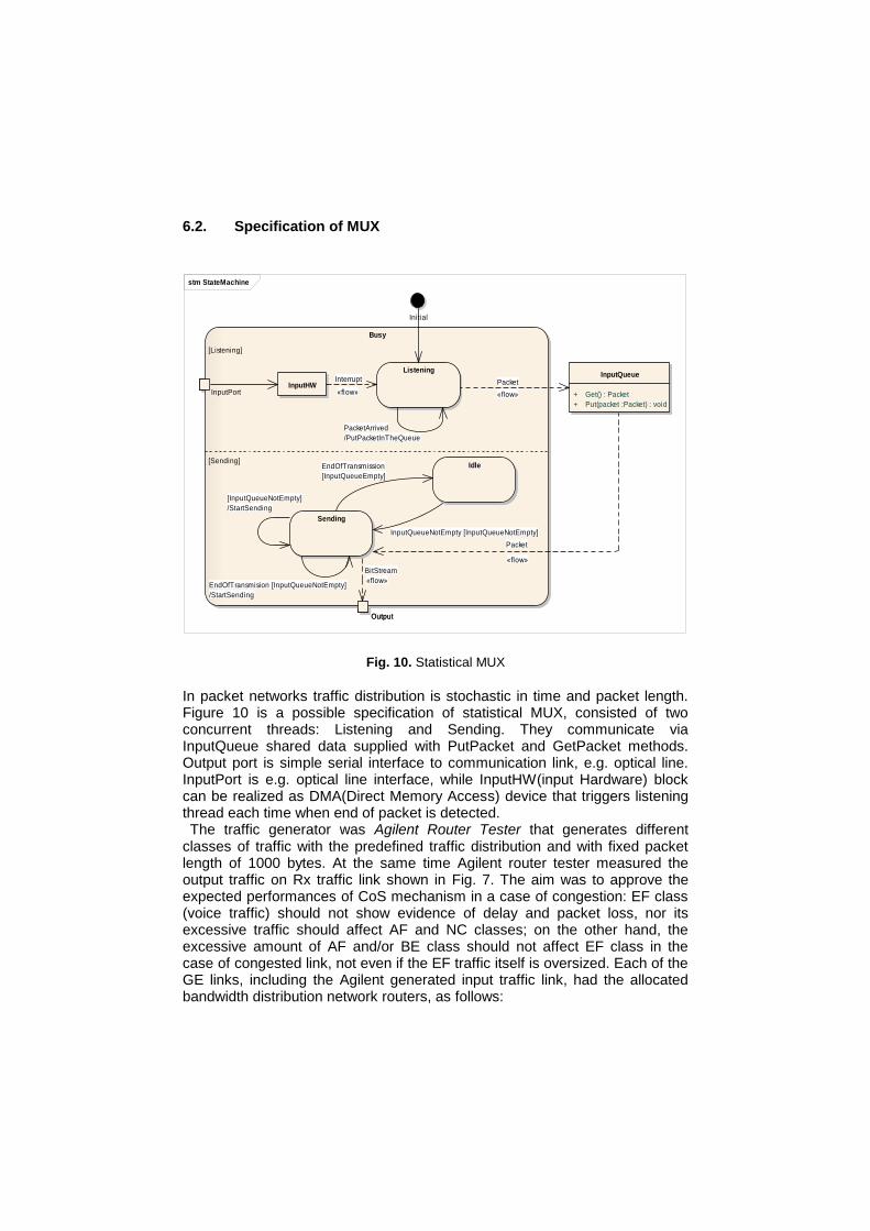
Fig. 10. Statistical MUX
In packet networks traffic distribution is stochastic in time and packet length. Figure 10 is a possible specification of statistical MUX, consisted of two concurrent threads: Listening and Sending. They communicate via InputQueue shared data supplied with PutPacket and GetPacket methods. Output port is simple serial interface to communication link, e.g. optical line. InputPort is e.g. optical line interface, while InputHW(input Hardware) block can be realized as DMA(Direct Memory Access) device that triggers listening thread each time when end of packet is detected. The traffic generator was Agilent Router Tester that generates different
classes of traffic with the predefined traffic distribution and with fixed packet length of 1000 bytes. At the same time Agilent router tester measured the output traffic on Rx traffic link shown in Fig. 7. The aim was to approve the expected performances of CoS mechanism in a case of congestion: EF class (voice traffic) should not show evidence of delay and packet loss, nor its excessive traffic should affect AF and NC classes; on the other hand, the excessive amount of AF and/or BE class should not affect EF class in the case of congested link, not even if the EF traffic itself is oversized. Each of the GE links, including the Agilent generated input traffic link, had the allocated bandwidth distribution network routers, as follows:
NC - 50Mbps - 5%;
AF - 400Mbps - 40%;
BE - 275Mbps - 27.5%;
EF - 275Mbps - 27.5%.
6.3. QoS/CoS – Test 1
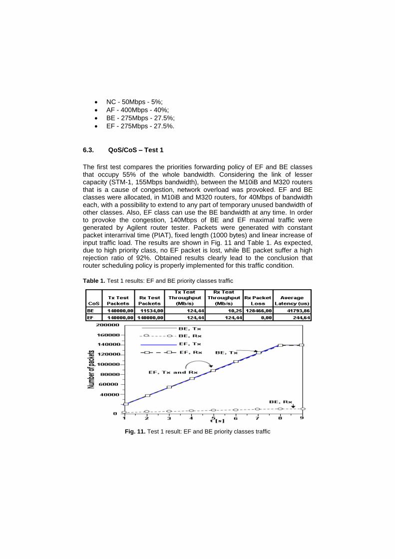
The first test compares the priorities forwarding policy of EF and BE classes that occupy 55% of the whole bandwidth. Considering the link of lesser capacity (STM-1, 155Mbps bandwidth), between the M10iB and M320 routers that is a cause of congestion, network overload was provoked. EF and BE classes were allocated, in M10iB and M320 routers, for 40Mbps of bandwidth each, with a possibility to extend to any part of temporary unused bandwidth of other classes. Also, EF class can use the BE bandwidth at any time. In order to provoke the congestion, 140Mbps of BE and EF maximal traffic were generated by Agilent router tester. Packets were generated with constant packet interarrival time (PIAT), fixed length (1000 bytes) and linear increase of input traffic load. The results are shown in Fig. 11 and Table 1. As expected, due to high priority class, no EF packet is lost, while BE packet suffer a high rejection ratio of 92%. Obtained results clearly lead to the conclusion that router scheduling policy is properly implemented for this traffic condition.
Table 1. Test 1 results: EF and BE priority classes traffic
Fig. 11. Test 1 result: EF and BE priority classes traffic
6.4. QoS/CoS – Test 2
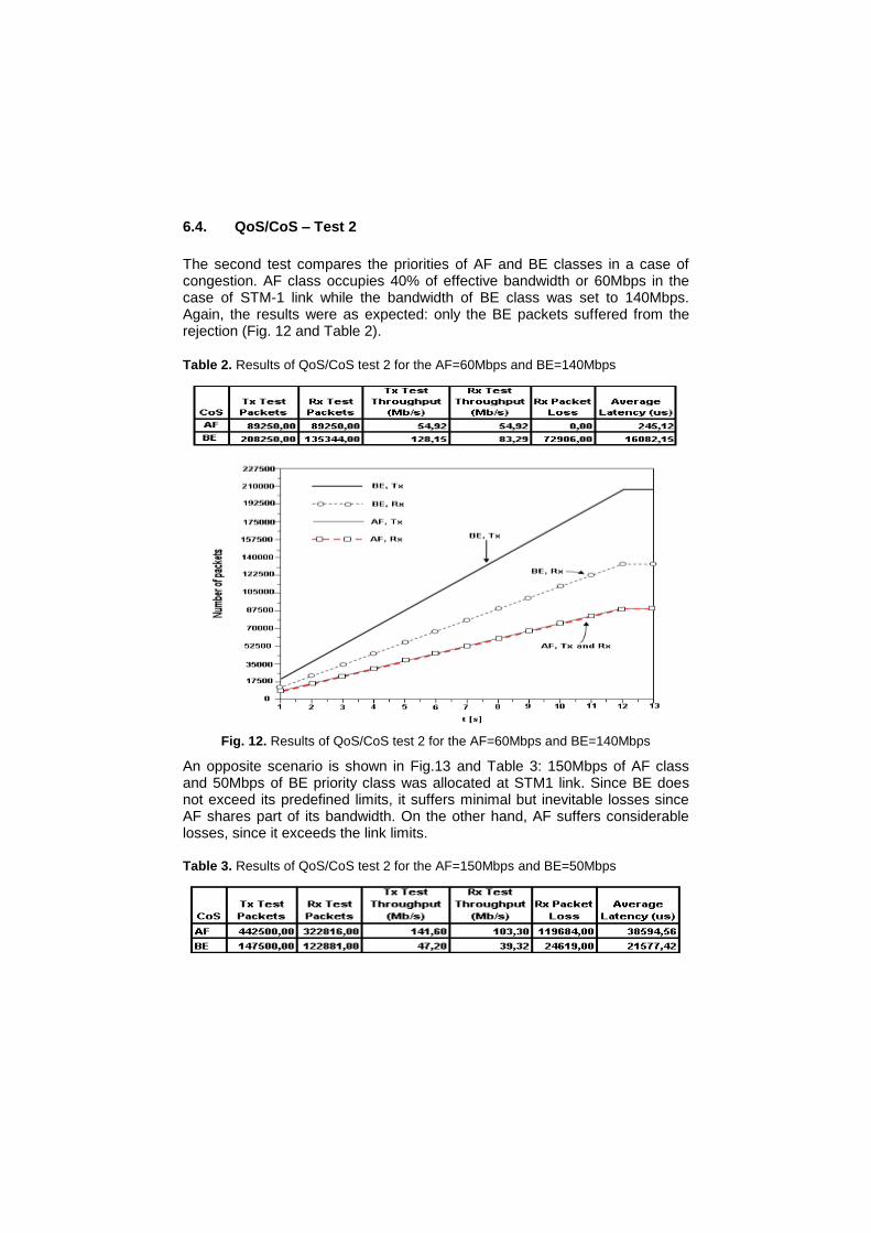
The second test compares the priorities of AF and BE classes in a case of congestion. AF class occupies 40% of effective bandwidth or 60Mbps in the case of STM-1 link while the bandwidth of BE class was set to 140Mbps. Again, the results were as expected: only the BE packets suffered from the rejection (Fig. 12 and Table 2).
Table 2. Results of QoS/CoS test 2 for the AF=60Mbps and BE=140Mbps
Fig. 12. Results of QoS/CoS test 2 for the AF=60Mbps and BE=140Mbps
An opposite scenario is shown in Fig.13 and Table 3: 150Mbps of AF class and 50Mbps of BE priority class was allocated at STM1 link. Since BE does not exceed its predefined limits, it suffers minimal but inevitable losses since AF shares part of its bandwidth. On the other hand, AF suffers considerable losses, since it exceeds the link limits. Table 3. Results of QoS/CoS test 2 for the AF=150Mbps and BE=50Mbps
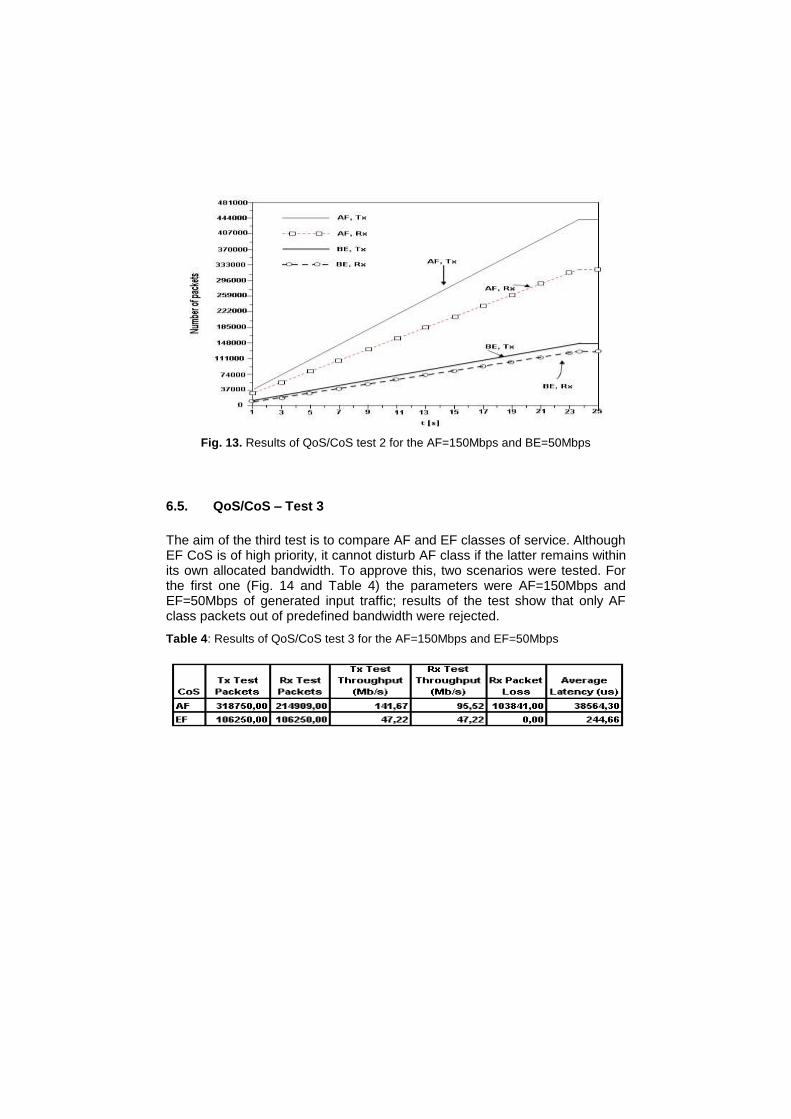
Fig. 13. Results of QoS/CoS test 2 for the AF=150Mbps and BE=50Mbps
6.5. QoS/CoS – Test 3
The aim of the third test is to compare AF and EF classes of service. Although EF CoS is of high priority, it cannot disturb AF class if the latter remains within its own allocated bandwidth. To approve this, two scenarios were tested. For the first one (Fig. 14 and Table 4) the parameters were AF=150Mbps and EF=50Mbps of generated input traffic; results of the test show that only AF class packets out of predefined bandwidth were rejected.
Table 4: Results of QoS/CoS test 3 for the AF=150Mbps and EF=50Mbps
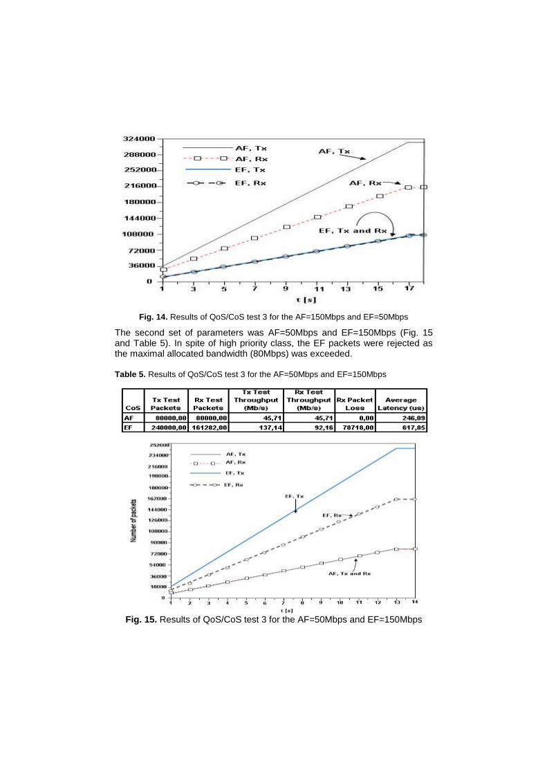
Fig. 14. Results of QoS/CoS test 3 for the AF=150Mbps and EF=50Mbps
The second set of parameters was AF=50Mbps and EF=150Mbps (Fig. 15 and Table 5). In spite of high priority class, the EF packets were rejected as the maximal allocated bandwidth (80Mbps) was exceeded. Table 5. Results of QoS/CoS test 3 for the AF=50Mbps and EF=150Mbps
Fig. 15. Results of QoS/CoS test 3 for the AF=50Mbps and EF=150Mbps
6.6. QoS/CoS – Test 4
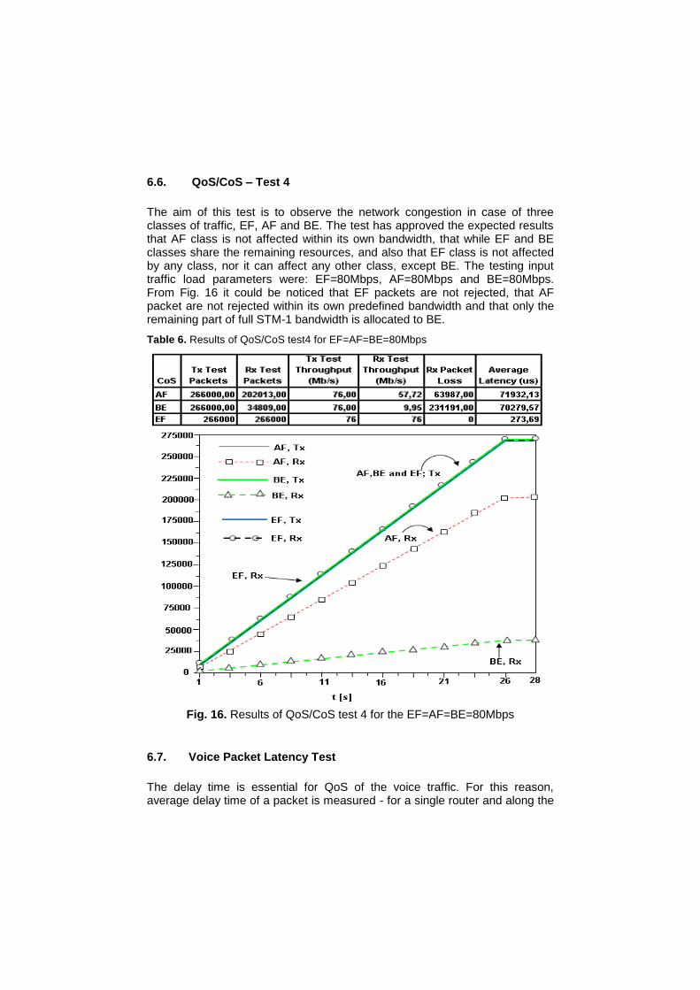
The aim of this test is to observe the network congestion in case of three classes of traffic, EF, AF and BE. The test has approved the expected results that AF class is not affected within its own bandwidth, that while EF and BE classes share the remaining resources, and also that EF class is not affected by any class, nor it can affect any other class, except BE. The testing input traffic load parameters were: EF=80Mbps, AF=80Mbps and BE=80Mbps. From Fig. 16 it could be noticed that EF packets are not rejected, that AF packet are not rejected within its own predefined bandwidth and that only the remaining part of full STM-1 bandwidth is allocated to BE.
Table 6. Results of QoS/CoS test4 for EF=AF=BE=80Mbps
Fig. 16. Results of QoS/CoS test 4 for the EF=AF=BE=80Mbps
6.7. Voice Packet Latency Test
The delay time is essential for QoS of the voice traffic. For this reason, average delay time of a packet is measured - for a single router and along the
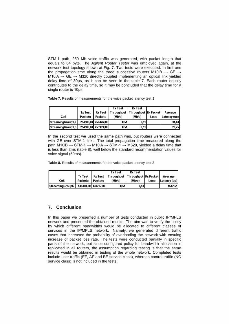
STM-1 path. 250 Mb voice traffic was generated, with packet length that equals to 64 byte. The Agilent Router Tester was employed again, at the network test topology shown at Fig. 7. Two tests were executed. In first one the propagation time along the three successive routers M10iB → GE → M10iA → GE → M320 directly coupled implementing an optical link yielded delay time of 30μs, as it can be seen in the table 7. Each router equally contributes to the delay time, so it may be concluded that the delay time for a single router is 10μs.
Table 7. Results of measurements for the voice packet latency test 1
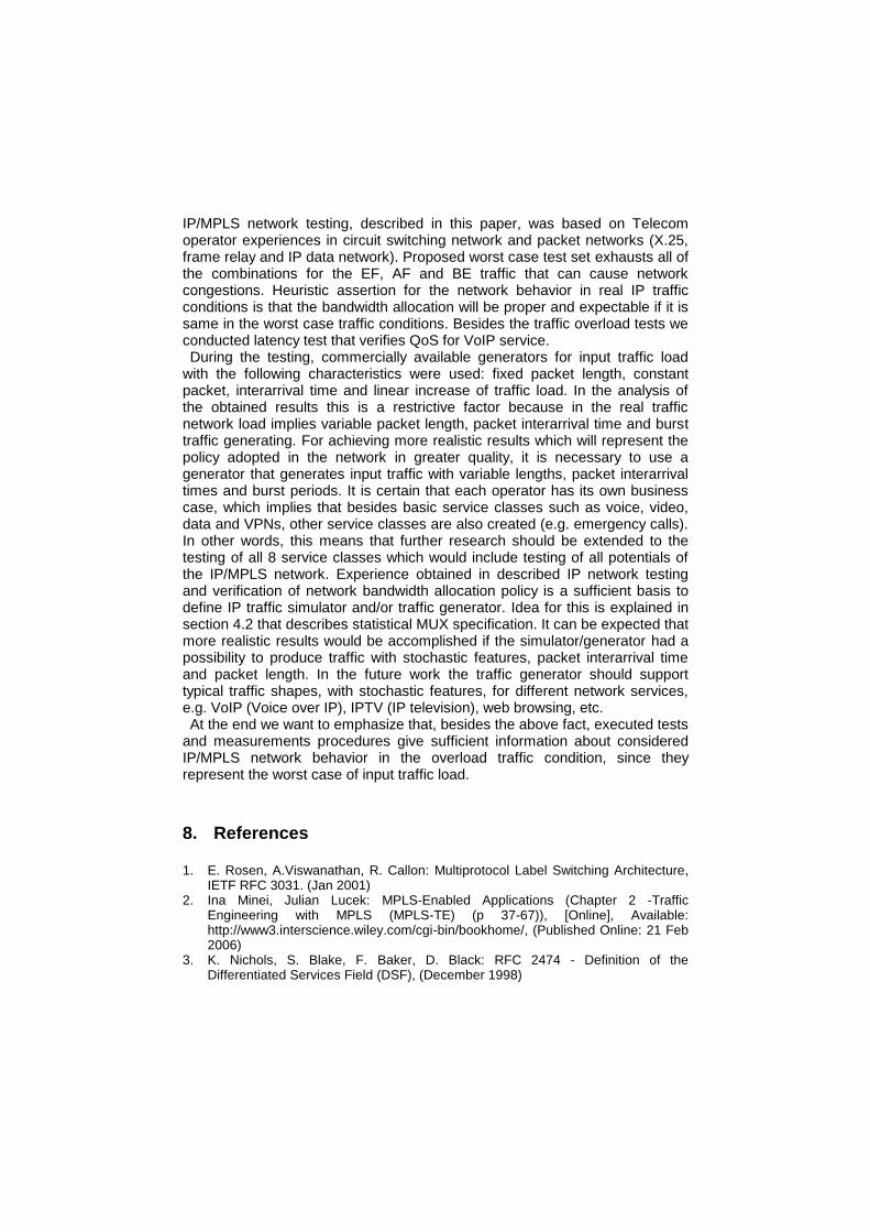
In the second test we used the same path was, but routers were connected with GE over STM-1 links. The total propagation time measured along the path M10iB → STM-1 → M10iA → STM-1 → M320, yielded a delay time that is less than 2ms (table 8), well below the standard recommendation values for voice signal (50ms).
Table 8. Results of measurements for the voice packet latency test 2
7. Conclusion
In this paper we presented a number of tests conducted in public IP/MPLS network and presented the obtained results. The aim was to verify the policy by which different bandwidths would be allocated to different classes of services in the IP/MPLS network. Namely, we generated different traffic cases that increased the probability of overloading the network with ensuing increase of packet loss rate. The tests were conducted partially in specific parts of the network, but since configured policy for bandwidth allocation is replicated in all routers, the assumption regarding testing is that the same results would be obtained in testing of the whole network. Completed tests include user traffic (EF, AF and BE service class), whereas control traffic (NC service class) is not included in the tests.
IP/MPLS network testing, described in this paper, was based on Telecom operator experiences in circuit switching network and packet networks (X.25, frame relay and IP data network). Proposed worst case test set exhausts all of the combinations for the EF, AF and BE traffic that can cause network congestions. Heuristic assertion for the network behavior in real IP traffic conditions is that the bandwidth allocation will be proper and expectable if it is same in the worst case traffic conditions. Besides the traffic overload tests we conducted latency test that verifies QoS for VoIP service. During the testing, commercially available generators for input traffic load
with the following characteristics were used: fixed packet length, constant packet, interarrival time and linear increase of traffic load. In the analysis of the obtained results this is a restrictive factor because in the real traffic network load implies variable packet length, packet interarrival time and burst traffic generating. For achieving more realistic results which will represent the policy adopted in the network in greater quality, it is necessary to use a generator that generates input traffic with variable lengths, packet interarrival times and burst periods. It is certain that each operator has its own business case, which implies that besides basic service classes such as voice, video, data and VPNs, other service classes are also created (e.g. emergency calls). In other words, this means that further research should be extended to the testing of all 8 service classes which would include testing of all potentials of the IP/MPLS network. Experience obtained in described IP network testing and verification of network bandwidth allocation policy is a sufficient basis to define IP traffic simulator and/or traffic generator. Idea for this is explained in section 4.2 that describes statistical MUX specification. It can be expected that more realistic results would be accomplished if the simulator/generator had a possibility to produce traffic with stochastic features, packet interarrival time and packet length. In the future work the traffic generator should support typical traffic shapes, with stochastic features, for different network services, e.g. VoIP (Voice over IP), IPTV (IP television), web browsing, etc. At the end we want to emphasize that, besides the above fact, executed tests
and measurements procedures give sufficient information about considered IP/MPLS network behavior in the overload traffic condition, since they represent the worst case of input traffic load.
8. References
1. E. Rosen, A.Viswanathan, R. Callon: Multiprotocol Label Switching Architecture, IETF RFC 3031. (Jan 2001)
2. Ina Minei, Julian Lucek: MPLS-Enabled Applications (Chapter 2 -Traffic Engineering with MPLS (MPLS-TE) (p 37-67)), [Online], Available: http://www3.interscience.wiley.com/cgi-bin/bookhome/, (Published Online: 21 Feb 2006)
3. K. Nichols, S. Blake, F. Baker, D. Black: RFC 2474 - Definition of the Differentiated Services Field (DSF), (December 1998)
4. OMG Unified Modeling Language (OMG UML), Superstructure, V2.1.2, OMG Document Number: formal/2007-11-02 Standard document URL: http://www.omg.org/spec/UML/2.1.2/Superstructure/PDF
5. Enterprise Architect-Free UML Tool Downloads for OOA/D Software Development, http://www.sparxsystems.com.au/products/ea/downloads.html
6. Allen Holub's UML Quick Reference, http://www.holub.com/goodies/uml/ 7. S. Blake, D. Black, M. Carlson, E. Davies, Z. Wang, W. Weiss: RFC 2475 - An
Architecture for Differentiated Services, (December 1998) 8. JUNOS MPLS Applications Configuration Guide: Configuring CoS for MPLS
[Online], Available:http://www.juniper.net/techpubs/software/junos/junos80/ swconfig80-cos/html/cos-mpls.html, (Published Online: 2007) 9. Juniper: Supported CoS Standards and features,
http://netscreen.com/techpubs/software/junos/junos91/swref-hierarchy/supported-cos-standards-and-features.html