Embed Size (px)
Citation preview
QoS-Aware Resource Allocation for Mobile EdgeNetworks: User Association, Precoding and Power
AllocationGuanchong Niu1, 2, Qi Cao1 and Man-On Pun1, 2, 3
1School of Science and Engineering, The Chinese University of Hong Kong, Shenzhen, China, 5181722Shenzhen Research Institute of Big Data, Shenzhen, China, 518172
3Shenzhen Key Laboratory of IoT Intelligent System and Wireless Network Technology, Shenzhen, China, 518172
Abstract—Mobile edge computing (MEC) can provide com-puting and storage services to user equipments (UEs) byutilizing edge nodes known as the small base stations (SBS’s)deployed at the edge of the network. The short-distance trans-mission nature between SBS’s and UEs makes the millimeter-wave (mmWave) communication empowered with multiple-input multiple-output (MIMO) hybrid precoding techniquesparticularly attractive for MEC. In this work, we considerthe UE-SBS association, precoding design and power allocationfor MEC networks endowed with mmWave MIMO. Morespecifically, the user association problem is first formulated asa max-k-cut (MkC) problem and then, solved by a distributedlocal-search algorithm. Next, the joint optimization of precodingand power allocation is cast into the difference of two convexfunctions (D.C.) programming framework before an iterativerank-constrained D.C. programming algorithm is developedto maximize the weighted sum-rate (WSR) of all UEs whiletaking into account the quality of service (QoS) requirementof each UE. Furthermore, the monotonic convergence of theproposed iterative algorithm is analytically proven. Finally,extensive computer simulation is conducted to demonstrate theeffectiveness of the proposed iterative algorithm.
Index Terms—Mobile Edge Computing, User Association,Hybrid Beamforming, D.C. Programming, Power Allocation.
I. INTRODUCTION
The explosive growth in both mobile data traffic and thenumber of mobile terminals as smartphones and tablets haspresented major challenges on the wireless network design[1], [2]. To meet these challenges, the future networks haveto minimize the transmission latency to support real-timeapplications without being overloaded by data exchangesbetween UEs and base stations [3]. To circumvent theseproblems, mobile edge computing (MEC) has recently beenproposed as one of the most promising techniques [4]–[8].In MEC, the computing and storage resources are deployedfrom the central cloud server to edge nodes (SBS’s) of thenetwork [9]. As a result, the computing task of stringent
This work was supported, in part, by the Shenzhen Institute ofArtificial Intelligence and Robotics for Society (AIRS) under grantNo. AC01202005001, the Shenzhen Science and Technology Inno-vation Committee under Grant No. ZDSYS20170725140921348 andJCYJ20190813170803617, and by the National Natural Science Foundationof China under Grant No. 61731018.
† Corresponding author, email: [email protected].
Cloud Server
SBS
SBS
SBS
Fig. 1. Illustration of the MEC system under consideration.
low-latency requirements can be processed by the proximateSBS’s without being sent to the cloud server. Furthermore, theclose proximity between UEs and SBS’s enables the networkto collect more recent UE information such as behaviors,locations and environment, which facilitates the network toprovide agile services.
Meanwhile, the millimeter wave (mmWave) transmissionendowed with massive antenna arrays has been adopted in thefifth generation (5G) wireless communication systems [10].The synergy of mmWave transmission and MEC has beenwell regarded as a strong candidate for the future wirelessnetworks. By exploiting the large available mmWave spec-trum and the high antenna gain [11], the mmWave massivemultiple-input multiple-output (MIMO) transmission enablesthe short-distance high-speed data communications betweenUEs and their associated SBS’s [12]. However, the implemen-tation of fully digital mmWave massive MIMO transmissionincurs prohibitively expensive hardware costs. To cope withthis problem, the hybrid analog and digital beamforminghas been proposed [13]–[15]. In hybrid beamforming, theprecoding process is divided into two phases, namely the
1

User A
ssociation
SINR Maximization
Interference
Minimization By MkC
Joint Beamform
ing
and power allocation
Convexity
Transformation
Rank Constrained D.C.
Programming
SBS Edge
Computing
Section Ⅳ
Section Ⅴ
Cloud Server
Fig. 2. Flowchart in this work.
analog precoding with a large number of phase shifters,and the digital precoding with a smaller number of RadioFrequency (RF) chains. By carefully designing the analogand digital precoders, it has been shown that the low-costhybrid beamforming can achieve comparable performance ascompared to the fully digital beamforming.
In addition, user association has become an importantproblem in MEC as SBS’s are expected to be denselydeployed with each SBS covering a much smaller area ascompared to the conventional macro base stations. Thus,a carefully designed user association can match each UEwith the best SBS by maximizing the transmission data ratewhile minimizing its incurred interference [16]. However, theuser association problem is NP-hard due to its combinato-rial nature. Some pioneering studies attempted to solve theproblem by simplifying the deployment scenarios. For in-stance, in [17], the association problem was addressed basedon the Euclidean distance without taking into account thedynamic nature of the wireless channel model. Furthermore,[18] proposed a user association algorithm based on thephysical resource block (PRB) table. In both [17], [18], userassociation was investigated without considering the potentialimpact caused by multiuser interference.
Finally, power allocation is considered as one of the mosteffective methods to achieve required quality of service (QoS)for each UE by better managing co-channel interference in
multiuser networks [19], [20]. However, joint precoding andpower allocation design is usually analytically intractable dueto its non-convex nature [21]. To circumvent this obstacle,[22] proposed to optimize the power allocation for the sum-rate capacity maximization problem by utilizing the water-filling algorithm, assuming that the spatial channels of allUEs are perfectly orthogonal. Clearly, this assumption isan issue of concern in practice. In addition, the task offinding the optimal precoding and power allocation designthat maximizes the spectral efficiency is very challenging dueto the fact that all system parameters under consideration arehighly coupled.
Motivated by the aforementioned challenges, this workstudies the MEC system equipped with mmWave MIMO asshown in Fig. 1. As depicted in Fig. 2, the user associationproblem is first transformed into an intra-SBS interferenceminimization problem before being solved by a distributedmax-k-cut (MkC)-based algorithm in Section IV. In contrastto the suboptimal resource allocation algorithm proposedin [23], we consider the user association problem for multipleSBS’s based on intra-SBS interference minimization. Finally,we cast the non-convex problem as a rank-constrained differ-ence of two convex functions (D.C.) programming problemto solve the precoding and power allocation in Section V.
In summary, the main contributions of this work aresummarized as follows:• We first propose a novel distributed MkC-based al-
gorithm for user association using practical wirelesschannel models. Furthermore, the performance boundsof the proposed algorithm are derived;
• Furthermore, joint precoding and power allocation isproposed using the rank-constrained D.C. programmingtechnique. More specifically, the original non-convex op-timization problem is formulated as a rank-constrainedD.C. programming problem before an iterative algorithmis devised to maximize the weighted sum-rate (WSR)with QoS constraints for each UE. The convergence ofthe proposed iterative algorithm is proven.
The rest of this paper is organized as follows. First, anintroduction to the D.C. programming techniques and theMkC problem is provided in Section II. Next, the MEC sys-tem model is presented in Section III before an MkC-basedalgorithm is developed for user association in Section IV.After that, an iterative joint precoding and power allocationalgorithm using the rank-constrained D.C. programming tech-niques is established in Section V followed by the derivationof the performance bound of the proposed iterative algorithmin Section VI. Finally, extensive computer simulation resultsare presented in Section VII.
Notation: Uppercase boldface and lowercase boldface let-ters are used to denote matrices and vectors, respectively. INrepresents the identity matrix with size N ×N . AT and AH
are the transpose and conjugate transpose of A, respectively.[a]i denotes the i-th element of vector a. In addition, ‖A‖stands for the `2 norm of A while |A| denotes the absolutevalue of A. |A| is the cardinality of the enclosed set A.
2

TABLE ISUMMARY OF KEY NOTATIONS.
Symbol DescriptionAk,n The entry of A representing the belonging of the n-th userVi The i-th vertexK The number of SBS’sa(φ, θ) Array response vector with azimuth angle φ and elevation
angle φNR The number of antennas in the receiverNT The number of antennas in the transmitterwk,u Analog beamforming vector employed by the u-th UE of the
k-th SBSHk,u The u-th UE’s channel model under the k-th SBSfk,u Digital beamforming vector for the u-th user of the k-th SBSFk Digital precoding matrix for UEs under the k-th SBSvk,u analog beamforming vector for the u-th user of the k-th SBSVk Analog precoding matrix for UEs under the k-th SBSp The set for all users’ power allocation vectorSk The maximal number of users for the k-th SBSΩku,j The sum of the weights of the edges from a vertex u in the
Set k to all the vertices in Set jωku,jq The weight between two verticesNk Nk The partition set for the k-th SBS with size |Nk| = Nk
Fu The reformulated digital precoder to release non-convex rankconstraint
F The set of digital precoder in the rank-constrained problemgu The effective array gain of theu-th UE of the k-th SBSτk,u The weight of rate for the u-th UE of the k-th SBSPk Transmit power constraint for the k-th SBSU (m) Eigenvectors corresponding to the N−1 smallest eigenvalues
of F (m)u
Furthermore, rank(A) and trace(A) represent the rank andtrace ofA, respectively.A 0 represents thatA is a positivesemi-definite matrix. Finally, ∇f(A) represents the gradientof function f(A).
Symbol: Table I summarizes the key symbols applied inthis paper.
II. PRELIMINARY KNOWLEDGE FOR D.C. PROGRAMMINGAND MkC PROBLEM
A. Review of D.C. Programming
In this section, a brief review of the D.C. programming isprovided. In general, the D.C. programming problem has thefollowing form:
minimizex∈Rn
f0(x)− g0(x) (1)
subject to fi(x)− gi(x) ≤ 0, i = 1, · · · ,M.
where the functions fi: Rn → R and gi: Rn → R for i =0, 1, · · · ,M are convex.
Clearly, the optimization problem in Equation (1) is notnecessarily convex. As a result, it is non-trivial to find theoptimal solution. To solve the D.C. programming problem,the convex-concave procedure (CCP) algorithm is well re-garded as one of the most successful algorithms among manyproposed solutions [24]. The CCP algorithm iteratively ap-proximates the original problem with a convexified problem
by linearizing gi, for i = 0, 1, · · · ,M , with its first-orderTaylor expansions. More specifically, the objective functionin the (m+1)-th iteration of the CCP algorithm is formulatedas
minimize f0(x)−g0(x(m))−〈∇g0(x(m)),x−x(m)〉 (2)
where x(m) represents the state at the m-th iteration.Since Equation (2) is convex, it can be straightforwardly
solved by most convex optimization software packages [25].Furthermore, by taking advantage of the convex property, the(m + 1)-th solution is always better than the m-th solution,which guarantees the convergence of the iterative algorithmstated in Equation (2). The detailed CCP algorithm can befound in [26].
B. Review of Capacitated MkC Problem
Fig. 3. Illustration of an MkC problem in a graph |V| = 8, |E| = 10 andk = 3. The maximal solution of this MkC problem is 6 + 5 + 5 = 16.
For the MkC problem, we are given a weighted graph H =(V, E) consisting of a vertex set and an edge set denotedby V and E , respectively. The goal is to partition V into knon-empty sets in such a way that the sum of the weights ofedges wij between different partitions is maximized as shownin Fig. 3. It is worth noting that the partition is not uniquein general. Some MkC-related problems are summarized asfollows:• MC: A special case of MkC when k = 2 [27].• Conventional MkC: Just divide V vertices into k disjoint
non-empty partitions without additional constraints [28].• Max Steiner k-cut: Each partition must include at least
one vertex from a given set T = t1, t2, · · · , tl ∈ V ,where l ≥ k [29].
• MkC with given sizes: The partitions V1,V2, · · · ,Vkmust satisfy |Vi| = si with a given set s1, s2, · · · , sk,for all 1 ≤ i ≤ k [30].
• Capacitated MkC: Given a set s1, s2, · · · , sk, thepartitions V1,V2, · · · ,Vk must satisfy |Vi| ≤ si [31].
Since the inherent NP-hardness, the capacitated MkC canonly find a locally optimal solution in polynomial time. Abinary edge formulation (i.e. wij = 0, 1) is proposed in [32],where the integer variable xij for i, j ∈ V is defined as:
xij =
1 if i and j are in the same partition,0 otherwise.
(3)
3

Thereby the MkC problem is formulated as the followinginteger linear programming (ILP) formulation [33]:
maximize∑
i,j∈V,i<jωij(1− xij) (4a)
subject to xih + xhj − xij ≤ 1, ∀i, j, h ∈ V, (4b)∑i,j∈Q,i>j
xij ≥ 1,∀Q ⊆ V, |Q| = k + 1, (4c)
xij ∈ 0, 1, ∀i, j ∈ V, (4d)
where constraints (4b) and (4c) are the triangle and cliqueinequalities respectively. Triangle inequality implies the log-ical conditions that if xih = 1 and xhj = 1 hold, then bytransitivity the value of xij should be 1 as well, meaningvertices i and j are in the same partition. Constraint (4c)imposes that at least two from every subset of k+ 1 verticeshave to be in the same partition. Constraints (4b) and (4c)imply that there are at most k partitions.
III. SYSTEM MODEL AND PROBLEM FORMULATION
A. MEC System Model
We consider an MEC system of K SBS’s serving N UEsas shown in Fig. 1. We denote by N = 1, 2, · · · , N theUE index set while Nk = 1, 2, · · · , Nk stands for theUE index set for UEs served by the k-th SBS. Furthermore,we assume that each SBS can serve maximal Sk users, i.e.,Nk ≤ Sk for k = 1, 2, · · · ,K. The set of k is denoted byK = 1, 2, · · · ,K.
Assuming that each UE can attach to only one SBS, wedefine A(n) = k to denote that the n-th UE is attachedto the k-th SBS. Using A(n), we further define a UE-SBSassociation matrix denoted by A of dimension K ×N . Theentry of A is given by :
Ak,n =
1 if A(n) = k,
0 otherwise,(5)
for k ∈ K and n ∈ N .
B. Downlink Transmission Model
As shown in Fig. 4, the SBS’s are equipped with mmWaveMU-MIMO systems, each with NRF RF chains and NTantennas aiming to transmit Nk data streams to Nk of Nreceivers with NR receive antennas. Furthermore, we assumethat SBS’s operate in orthogonal channels. As a result, inter-SBS interference is not considered in the sequel.
Following the same design commonly implemented in theliterature [34], only one data stream is designated to eachscheduled receiver. We use sk ∈ CNk to denote the data tobe transmitted with E
[sks
Hk
]= 1
NkINk .
Without loss of generality, we focus our following dis-cussions on the k-th SBS. The hybrid precoding systemfirst multiplies sk with the digital precoding matrix Fk =[fk,1,fk,2, · · · ,fk,Nk ] with fk,u ∈ CNRF×1 being the dig-ital beamforming vector for the u-th UE. After that, theoutput signal is multiplied by the analog precoding matrix
Vk = [vk,1,vk,2, · · · ,vk,NRF ] with vk,u ∈ CNT×NRF . Theresulting precoded signal xk of length NT can be expressedas
xk = Vk · Fk · sk = Vk∑n∈N
Ak,nfk,nsk,n. (6)
The precoded signal xk is then broadcast to Nk UEs. Thesignal received by the u-th UE associated with the k-th SBSis given by [35]
yk,u = Hk,uxk + nk,u
= Hk,uVkfk,usk,u
+Hk,uVk∑n∈Nn 6=u
Ak,nfk,nsk,n
︸ ︷︷ ︸Intra-SBS Interference
+nk,u, (7)
where Hk,u ∈ CNR×NT is the MIMO channel matrixbetween the k-th SBS and its u-th UE, and nk,u is thecomplex additive white Gaussian noise with zero mean andvariance equal to σ2
k,u.Assuming that UEs under consideration are all low-cost
terminals with analog-only decoding, the decoded signalaccording to sk,u is given by
sk,u = wHk,uHk,uVkfk,usk,u +wH
k,unk,u, (8)
where wk,u of length NR is the analog beamforming vectoremployed by the u-th UE of the k-th SBS with the powerconstraint of ‖wk,u‖2 = 1 and
nk,u = Hk,uVk∑n∈Nn 6=u
Ak,nfk,nsk,n + nk,u. (9)
Note that the first term in Equation (8) stands for the desiredsignal while the second term nk,u is the sum of the receivernoise and interference from other UEs in the same SBSnetwork.
C. Channel Model
It has been shown that the mmWave wireless channel canbe well modeled by the Saleh-Valenzuela model [15]. Weassume that the channel state information (CSI) is perfectlyknown. Following the same technique proposed in [34], eachscatter is assumed to contribute only one propagation path.As a result, the u-th UE’s channel model under the k-th SBScan be modeled as
Hk,u =
√NTNRLk,u
Lk,u∑l=1
αk,u,l×
aR(φrk,u,l, θrk,u,l) · aHT (φtk,u,l, θ
tk,u,l), (10)
where Lk,u is the number of scatters of the u-th UE’schannel. Furthermore, αk,u,l is the complex path gain withzero mean while
θrk,u,l, φ
rk,u,l
and
θtk,u,l, φ
tk,u,l
are the
azimuth and elevation angles of arrival (AoA) and anglesof departure (AoD), respectively. Finally, a is the arrayresponse vector. For the uniform planar array (UPA) with size
4

Digital Precoder
Analog Precoder
x
Analog Decoder
Transmitter
The 1-st User
User Beam Scheduling
Analog Decoder
The u-th User
User D
ata Stream
Fig. 4. Block diagram of the hybrid precoding system under consideration.
W ×Q considered in this work, the array response vector ais represented by
a(φ, θ) =1√WQ
[1, ejκd(sinφ sin θ+cos θ),
· · · , ejκd((P−1) sinφ sin θ+(Q−1) cos θ)]T, (11)
where κ = 2πλ is the wavenumber and d is the distance
between two adjacent antennas.
D. Analog Precoding
We firstly design the analog precoding schemes on bothUEs and SBS’s. The power constraints of analog precoderscan be formulated by
|[wk,u]i|2 = 1/NR, i = 1, 2, · · · , NR;
|[vk,u]i|2 = 1/NT , i = 1, 2, · · · , NT . (12)
It is well-known that distinct array response vectors areasymptotically orthogonal as the number of antennas in anantenna array goes to infinity [36], i.e.
limN→+∞
aH(φtk,u, θtk,u) · a(φt`,v, θ
t`,v) = δ(k − `)δ(u− v).
(13)However, since the infinite number of antennas is not
practical, the residual interference must be taken into consid-eration for the analog precoding design. Recalling the channelmodel in Equation (10), we can asymptotically orthogonalize
the transmitted signals by optimizing the design of wk,u andvk,u with given user association:
w∗k,u,v∗k,u = arg maxwk,u,vk,u
Mk∑u=1
log2 (1 + SINR (wk,u, vk,u))
(14)subject to vk,u ∈ Btk,u,
wk,u ∈ Brk,u,
where Btk,u and Brk,u are the array response vectors for theSBS and UE denoted by
Btk,u =[aT (φtk,u,1, θ
tk,u,1), · · · ,aT (φtk,u,Lu , θ
tk,u,Lu)
],
Brk,u =[aR(φrk,u,1, θ
rk,u,1), · · · ,aR(φrk,u,Lu , θ
rk,u,Lu)
].
(15)
The analog precoders are selected from the array responsevectors by taking advantage of the perfect CSI.
Furthermore, SINR (wk,u, vk,u) is given by
SINR (wk,u, vk,u) =|wH
k,uHk,uvk,u|2∑n∈N ,n6=u
Ak,n|wHk,uHk,uvk,n|2 +
1
γ
,
(16)where γ = P
Nσ2u
is the SNR for each user. In deriving theresults above, we have assumed fk,ufHk,u ≈ Ik. As a result,the optimal analog precoders at both transmitter and receivercan be straightforwardly found by exhaustively searching inthe feasible sets of Btk,u and Brk,u.
5

E. Problem Formulation
For notational simplicity, we denote by gHk,u the effectivearray gain of the u-th UE with
gHk,u = wHk,uHk,uVk. (17)
Then, the channel capacity of the u-th UE under the k-thSBS is given by
Rk,u = log2
(1 +
pk,u|gHk,ufk,u|2∑i∈N Ak,npk,i|gHk,ufk,i|2 + σ2
k,u
).
(18)Subsequently, the system WSR can be formulated as
Rtot =
K∑k=1
Nk∑u=1
τk,uRk,u(pk,Fk,A), (19)
where τk = [τk,1, τk,2, · · · , τk,Nk ] with∑Nku=1 τk,u = Nk
is the vector containing the corresponding weights for UEswhile pk = [pk,1, pk,2, · · · , pk,Nk ] with
∑Nku=1 pk,u ≤ Pk is
the vector containing the transmit power of the k-th SBS. Wefurther denote by p = [p1, · · · ,pK ] the vector containing allusers’ power allocation.
Finally, the optimal design of user scheduling and hybridprecoding matrices, as well as power allocation can beformulated as
P1 : maximizep,F ,A
Rtot(p,F ,A) (20)
subject to C1 : ‖Vkfk,u‖2 = 1, ∀u ∈ Nk,∀k ∈ K,
C2 :
Nk∑u=1
pk,u ≤ Pk, ∀k ∈ K,
C3 : Rk,u ≥ λk,u, ∀u ∈ Nk,∀k ∈ K,
C4 :
N∑n=1
Ak,n ≤ Sk, ∀k ∈ K,
C5 :
K∑k=1
Ak,n = 1, ∀n ∈ N .
where C1 ensures that each RF chain is of unit power.The total transmit power is limited by Pk as shown in C2
while C3 ensures that the QoS for the u-th UE of the k-th SBS with a minimum data rate of λk,u. In addition, inconstraints C4 and C5, the number of UEs served by oneSBS is constrained while one UE can only be attached toone SBS for transmission.
Since the problem P1 is highly non-convex, it is analyt-ically intractable to derive a closed-form solution to P1. InSection IV, we first formulate the UE association problemas a capacitated MkC problem, which can be solved bya distributed local-search algorithm. After that, a generalrank-constrained D.C. programming technique is developedin Section V to solve the local optimal digital precoderand power allocation by approximating the problem in eachiteration as a standard convex optimization problem.
IV. MAX-k-CUT PROBLEM FOR USER ASSOCIATION
In the sequel, the user allocation is designed to minimizethe interference caused by the side lobe of beamformersbased on the proposed capacitated MkC algorithm before theperformance bounds are derived.
Since the antenna number is finite in practice, the residualinterference must be considered in the analog precoding de-sign. Recalling the channel model presented in Equation (10),we can asymptotically orthogonalize the transmitted signalsby optimizing the design of wu and vu:
P2 : maximizeA
K∑k
Nk∑u=1
log2 (1 + SINR (wk,u, vk,u))
(21)
subject to∑n∈N
Ak,n ≤ Sk, ∀k ∈ K;∑k∈K
Ak,n = 1, ∀n ∈ N .
A. A Distributed Local-Search Algorithm
Fig. 5. The weight of two vertices (UEs).
As exhibited in [37], the user association problem is NP-hard since the number of possible combinations between UEsand SBS’s is
∏Kj=1
(N−∑j−1k=0 NkNj
), where we set N0 = 0.
To cope with this obstacle, a heuristic algorithm is proposedby exploiting the interference minimization. The intra-SBSinterference minimization problem is formulated as
minimizeA
K∑k=1
Nk∑u=1
∑n∈Nn 6=u
Ak,n|wHk,uHk,uvk,n|2. (22)
In the MEC system model, we assume that the channelsoperated in different SBS’s are orthogonal. As a result, theinter-SBS interference can be eliminated by the orthogonalchannels. Inspired by the MkC technique in Section II-B,we can transform the intra-SBS minimization problem in
6

Equation (22) to maximize the inter-SBS interference asfollows:
maximizeA
Itot =
K∑k 6=jk,j=1
Nk∑u=1
∑n∈Nn 6=u
Ak,n|wHk,uHk,uvj,n|2.
(23)
Thus, as shown in Fig. 5, the counterpart weight betweentwo vertices (UEs) is given by
ωku,jq =
0, if j = k,
|wHk,uHk,uvj,q|2, otherwise.
(24)
In this way, the problem in Equation (24) can be trans-formed as an MkC problem, which can be solved using adistributed local-search algorithm. We can regard an SBS net-work as one “cut”. To maximize the inter-SBS interference,we propose a local-search algorithm to solve the problem P2.We first denote by Ωku,j the sum of the weights of the edgesfrom a vertex u in Set k to all the vertices in Set j. Ωku,jtakes the following form:
Ωku,j =
Nj∑q=1
ωku,jq . (25)
A distributed local-search algorithm for the capacitatedMkC problem [32] is given as follows:
1) Initialization: Partition the UEs into K sets,N1,N2, · · · ,NK before randomly initializing∑nAk,n ≤ Sk, i.e., Nk ≤ Sk for k = 1, 2, · · · ,K.
2) Iterative Step: Determine if there is an association pairq in Set j and u in Set k for which
NkΩku,k +NjΩjq,j > NkΩjq,k +NjΩku,j . (26)
If such a pair exists, we reassign the q-th UE to thek-th SBS while the u-th UE to the j-th SBS.
3) Termination: Stop the iteration when all pairs violateEquation (26), i.e.,
NkΩku,k +NjΩjq,j ≤ NkΩjq,k +NjΩku,j . (27)
for all k, j ∈ K and u ∈ Nk, q ∈ Nj .The computational complexity of the local-search algo-
rithm can be analyzed as follows: In each iteration, one UEneeds to examine at most N − 1 times to check if any pairsatisfies Equation (26). Thus, the local-search algorithm hascomputational complexity of the order of O(N2).
Since no central coordinators are assumed in the searchalgorithm proposed above, the proposed iterative algorithmcan be executed in a distributed manner. In the MEC system,we consider a fully coordinated scenario where the SBS’scollaborate to address the user association problem. SBS’sare able to share with each other the CSI of UEs. Since theinter-SBS interference can be eliminated by the orthogonalchannels, we can optimize the user association using theproposed local-search algorithm by maximizing the inter-SBSinterference.
B. Worst-Case Analysis
The theorem below characterizes the performance lowerbound of the distributed local-search algorithm for all K ≥ 2.We define
Ils =
K∑k=1
Nk∑u=1
Ωku,k. (28)
where Ils is the solution given by the local-search algorithm.
Theorem 1. Assuming that the maximal value of a MkCproblem is Imax. The solution obtained using the local-searchalgorithm has a value no smaller than 1− 1
K of the optimalsolution value, i.e.,
IlsImax
≥ 1− 1
K. (29)
Proof. See Appendix A.
Since it is non-trivial to analytically evaluate Equation (28),we will use computer simulation to confirm the effectivenessof our proposed association algorithm in Section VII.
V. PROPOSED ITERATIVE ALGORITHM FORRANK-CONSTRAINED D.C. PROBLEM
In this section, we will derive the optimal digital precoderand power allocation at each SBS for a given associationmatrix A and a set of analog precoders. Without loss of gen-erality, we focus the following discussion on the k-th groupwhile omitting the subscript k for presentational simplicity.In addition, we set the number of UEs attached to each SBSto N while the maximum total transmit power P0.
Then, the optimal design of the precoding matrices as wellas power allocation can be formulated as
P3 : maximizep,F
Rtot(p,F ) (30)
subject to C1 : ‖V fu‖2 = 1, u = 0, 1, · · · , N ,
C2 :
N∑u=1
pu ≤ P0,
C3 : Ru ≥ λu, u = 0, 1, · · · , N .
Since the tasks of precoding design and power allocationare highly coupled, we will propose a joint optimizationalgorithm to maximize the WSR in this section.
A. Rank-constrained D.C. problem
It can be easily seen that the challenge in solving P3 isthe non-convexity of Rtot(p,F ). To cope with this problem,we first express the digital precoder as
Fu = pufufHu , (31)
with constraints rank(Fu) ≤ 1 and Fu 0.Furthermore, the constraints C1 and C2 in P3 can be
transformed asN∑u=1
pu‖V fu‖2 =N∑u=1
V FuVH ≤ P0. (32)
7

It is worth noting that the optimal digital precoder f∗u is theeigenvector corresponding to the only non-zero eigenvalue p∗uof optimal F ∗u , where p∗u is the optimal power allocation [38].The variable pu is designed to ensure that C1 in P3 issatisfied.
Substituting Equation (31) into Equation (18), we have
Ru(Fu) = log2
1 +gHu Fugu∑N
i=1i 6=u
gHu Figu + σ2u
= log2
N∑i=1
gHu Figu + σ2u
− log2
N∑i=1i6=u
gHu Figu + σ2u
. (33)
Thereby, P3 can be reformulated as a D.C. problem witha rank constraint:
P4 : maximizeF
f(F)− g(F) (34)
subject to C1 :
N∑u=1
V H FuV ≤ P0,
C2 : Ru ≥ λu, u = 1, 2, · · · , N ,C3 : Fu 0, u = 1, 2, · · · , N ,C4 : rank(Fu) ≤ 1, u = 1, 2, · · · , N ,
where F = [F1, F2, · · · , FN ] and
f(F) =
N∑u=1
τu log2
N∑i=1
gHu Figu + σ2u
, (35)
g(F) =
N∑u=1
τu log2
N∑i=1i 6=u
gHu Figu + σ2u
. (36)
Next, we propose to transform the QoS constraint C2 intoa convex constraint as follows:
gHu Fugu + (1− 2λu)
N∑i=1i6=u
gHu Figu + σ2u
≥ 0. (37)
In the following, we devise an iterative algorithm tosolve P4 as a standard D.C. programming problem by firstignoring C4. More specifically, the optimal F∗ is obtainedby iteratively solving Fu for u = 1, 2, · · · , N . Similar to theprocedures in [26], the iterative algorithm gives the optimalF
(m+1)u at the m-th iteration by solving the following convex
problem (See Appendix B):
maximizeFu
f(Fu)− g(F (m)u )− 〈5g(F (m)
u ), Fu − F (m)u 〉
(38)subject to C1, C2, C3 in P4,
where 〈·〉 denotes the inner product of two matrices, i.e.,〈A,B〉 = trace(ATB). The gradient of g(F (m)) can becomputed as
5g(F (m)u ) =
N∑j=1j 6=u
wj/ ln 2∑Ni=1i 6=jgHu Figu + σ2
j
gjgHj . (39)
It is worth noting that 〈5g(F(m)u ), Fu−F (m)
u 〉 is a real valuesince 5g(F
(m)u ) and Fu − F (m)
u are both Hermitian.
B. The General RCOP
To solve P4, we will first introduce a rank constrained op-timization problem (RCOP). Inspired by RCOP, we will thenpropose an iterative algorithm to solve P4 by formulating aconvex optimization problem in each iteration.
We now consider the rank constraint C4 in P4. A generalRCOP to optimize a convex objective subject to a set ofconvex and rank constraints can be formulated as follows:
P5 : minimizeX
f(X) (40)
subject to X 0;
X ∈ C;rank(X) ≤ r,
where f(X) is a convex function, C is the set of given convexconstraints and X ∈ CN×N is a general positive semidefinitematrix.
As shown in [39], RCOP can be solved by an iterativemethod to gradually approach the constrained rank. In them-th iteration, we solve the following semidefinite program-ming (SDP) problem:
minimizeX(m+1),e(m)
f(X(m+1)) + we(m+1) (41)
subject to X(m+1) 0,
X(m+1) ∈ C,e(m+1)IN−r −U
(n)HX(m+1)U (m) 0,
e(m+1) ≤ e(m),
where w > 0 is the weighting factor. Using the eigenvalue de-composition (EVD), U (m) ∈ CN×(N−r) is the orthonormaleigenvectors corresponding to the N−r smallest eigenvaluesof X(m) solved in the previous iteration. In the first iterationwhere m = 0, e(0) is the (N − r)-th smallest eigenvalue ofX(0) that can be obtained by
minimizeX(0)
f(X(0)) (42)
subject to X(0) 0;
X(0) ∈ C,
and U (0) is the eigenvectors corresponding to N−r smallesteigenvalues of X(0).
8
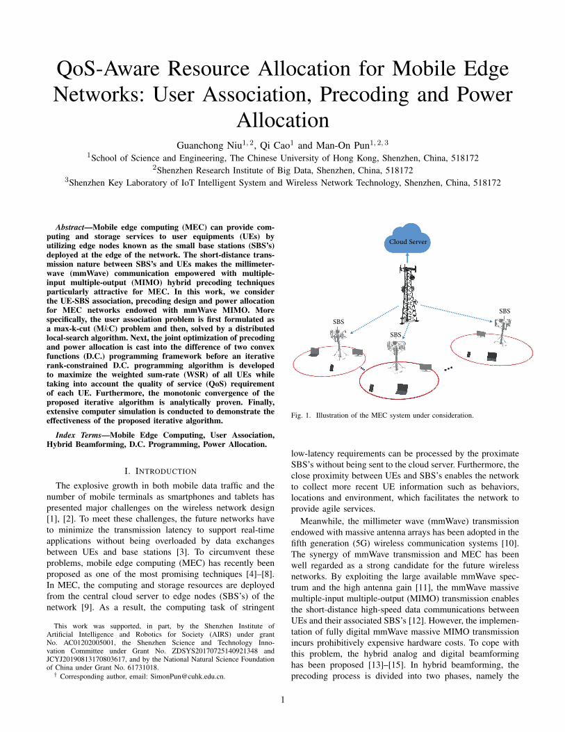
C. Iterative Algorithm for P4
It is straightforward to prove that Equation (38) is aconcave optimization problem as shown in Section V-A.By combining P4 and P5, an iterative algorithm for therank-constrained D.C. programming problem is derived. Theoptimal g(F (m+1)) in the m-th iteration is given by solvingthe following convex problem:
P6 : minimizeFu,e(m+1)
t(Fu, e(m+1)) (43)
subject to C1 :
N∑u=1
V H FuV ≤ N ,
C2 : Ru ≥ λu, u = 1, 2, · · · , N ,C3 : Fu 0,
C4 : e(m+1)IN−1 −U (m)H FuU(m) 0,
C5 : e(m+1) ≤ e(m),
where U (m) is the eigenvectors corresponding to the N − 1
smallest eigenvalues of F (m)u and t(Fu, e
(m+1)) has thefollowing form:
t(Fu, e(m+1)) (44)
=g(F (m)u ) + 〈∇g(F (m)
u ), Fu − F (m)u 〉 − f(Fu) + we(m+1).
P6 is indeed a standard convex optimization problem thatcan be solved via available convex software packages, such asCVX [25]. C1 ensures the total power constraint and C2 guar-antees the QoS constraint for each UE. Furthermore, C3, C4
and C5 are the constraints followed from Equation (41) inwhich we set r = 1. The proposed iterative algorithm issummarized in Algorithm 1. In each iteration, we solve aD.C. programming problem and update the optimal F ∗(m)
u . Ifthe WSR t(m) can no longer be improved, the digital precoderFu+1 of the (u+ 1)-th UE is then optimized successively inthe same manner.
Finally, we analyze the computational complexity of theproposed rank-constrained D.C. programming algorithm. Ineach iteration, an SDP problem is derived as shown in P6.The existing SDP solver based on the interior point methodhas computational complexity of the order of O(N4
k ) asFu ∈ CNk×Nk [39]. Furthermore, the EVD conducted ineach iteration has computational complexity of the order ofO(N3
k ). As a result, the complexity of the proposed algorithmis of the order of O(N4
k ) in each iteration.
D. Convergence Analysis
In the following, we provide the convergence analysisof the proposed iterative algorithm for solving the rank-constrained D.C. programming problem.
As the function g(Fu) is concave, its gradient ∇g(Fu) issuper-gradient. Therefore, we have
g(Fu) ≤ g(F (m)u ) + 〈∇g(F (m)
u ), Fu − F (m)u 〉. (45)
Algorithm 1 Proposed Iterative Algorithm for Rank-constrained D.C. ProblemInput:
Effective channel: g1, g2, · · · , gN ;Random initialization of F (0)
u , u = 1, 2, · · · , N ;Initial information: s, s′, t(F (0)
u , e(0));Initialize U (0), e(0) by solving Equation (42);Stop criterion: ε1, ε2.
Procedures:1: while |(s′ − s)/s| ≤ ε1 do2: Update s: s = s′
3: for 0 ≤ u ≤ N do4: m = 05: while |(t(F (m+1)
u , e(m+1))−t(F (m)u , e(m))|≤ε2 do
6: Obtain the optimal value t(m+1) of objectivefunction and F (m+1)
u , e(m+1) in Equation (43)7: Update U (m) from F
(m+1)u via EVD
8: Update m = m+ 19: end while
10: end for11: Update s′: s′ = t(m+1)
12: end while13: Outputs: F∗ = [F
∗(m)1 , F
∗(m)2 , · · · , F ∗(m)
N].
Since e(m+1) ≤ e(m) and F(m)u is feasible to Equa-
tion (43), it follows:
g(F (m+1)u )− f(F (m+1)
u ) + e(m+1) (46)
≤g(F (m)u ) + 〈5g(F (m)
u ), Fu − F (m)u 〉 − f(Fu) + e(m),
≤g(F (m)u )− f(F (m)
u ) + e(m),
which shows that the solution F (m+1)u is always better than
or equal to the previous solution F (m)u . Thus, the algorithm
must converge to a critical point.
VI. PERFORMANCE ANALYSIS
In this section, we will derive the performance upper andlower bounds of the proposed scheme. We will first beginwith the analog-only scheme. The expected capacity is givenby
E[Rk,u] =E [log2 (1 + ρ)] ,
=E
[log2
(1 +|w∗Hk,uHk,uv
∗k,u|2
1/γ + Ik,u
)], (47)
where Ik,u is the received interference represented as
Ik,u =∑n∈Nn 6=u
Ak,n|w∗Hk,uHk,uv∗k,n|2. (48)
From Equations (10) and (13), the optimal array responsevectors in transmitter and receiver are denoted by [15]
w∗k,u = aR(φrk,u,l∗ , θrk,u,l∗), (49)
v∗k,u = aT (φtk,u,l∗ , θtk,u,l∗). (50)
9

Proposition 1. If the optimal analog beamformers are de-signed as w∗k,u = aR(φrk,u, θ
rk,u) and v∗k,u = aT (φtk,u, θ
tk,u),
respectively, the following inequality holds:∑n∈Nn 6=u
Ak,n|w∗Hk,uHk,uv∗k,n|2 ≤ Z(Nk − 1)Ξ. (51)
where Ξ is a constant and Z = D2k,uα
2k,u.
Proof. See Appendix C.
Recalling Equation (47), the expected downlink capacityfor each UE can be rewritten as
E[Rk,u] = E[log2
(1 +
Z
1/γ + Y
)], (52)
where
Z = |w∗Hk,uHk,uv∗k,u|2,
= D2k,uα
2k,u, (53)
From Equation (49), we have
Y =∑n∈Nn 6=u
Ak,n|w∗Hk,uHk,uv∗k,n|2
= D2k,uα
2k,u
∑n∈Nn 6=u
Ak,n∣∣v∗Hk,uv∗k,n∣∣2 ,
= Z∑n∈Nn 6=u
Ak,n∣∣v∗Hk,uv∗k,n∣∣2 . (54)
Proposition 2. The lower and upper bounds of the sum-ratecapacity can be given by∫ ∞
0
log2(1+x)dFX(x) ≤ E[Rk,u] ≤∫ ∞
0
log2(1+z)dFZ(z),
(55)where FX(x) and FZ(z) are the CDF of SINR and Z,respectively.
Proof. From Proposition 1, Y can be upper bounded by
Y ≤ Z(Nk − 1)Ξ, (56)
where 0 ≤ Ξ ≤ 1 with Ξ being the expected residualinterference power between distinct beams. In our proposedsystem, the beams will be selected and grouped to reducethe residual interference. Clearly, Ξ = 0 if the number ofantennas goes to infinity or the steering vectors of differentusers are strictly orthogonal. In contrast, Ξ = 1 if differentUEs have same AoDs. In general, the value of Ξ can benumerically derived between 0 and 1.
Capitalizing on the Extreme Value Theory [40], we canderive the cumulative distribution function (CDF) of Z as
FZ(z) = 1− e− zC , (57)
where C = 2NTNR/Lk,u. By setting Ξ = 0, i.e., theinterference is totally removed, we have
E[Rk,u] ≤∫ ∞
0
log2(1 + z)dFZ(z). (58)
Finally, the CDF of the SINR lower bound can be givenby
FX(x) = 1− e−x
Cγ(1−Ξ(Nk−1)x) . (59)
The detailed derivation can be found in Appendix D.Using the CDF above, the lower bound of the sum-rate
capacity can be derived as
E[Rk,u] ≥∫ ∞
0
log2(1 + x)dFX(x). (60)
It is analytically intractable to obtain a closed-form solu-tion to Equation (58). We will show the numerical results insimulation section.
Note that the upper bound is achieved if the interferencefrom other UEs can be eliminated completely. Furthermore,since the number of transmitter antennas is finite in practice,the analog beamforming vectors shown in Equation (14) andEquation (16) inevitably incur residual inter-user interference.Thereby, digital precoders as well as power allocation areutilized to suppress the residual interference.
VII. SIMULATION RESULTS
In this section, we will use computer simulations to con-firm the performance of the proposed UE-SBS associationand rank-constrained D.C. programming algorithms. In thesimulations, we consider a system of multiple SBS’s eachequipped with a 4×4 UPA (i.e., NT = 16) and N ground UEseach equipped with a 2× 2 UPA (i.e. NR = 4). The numberof paths in the wireless channel model is set to Lu = 4. Wemodel the azimuth AoAs/AoDs uniformly distributed over[0, 2π] while the elevation AoAs/AoDs uniformly distributedover [−π/2, π/2], respectively. For each computer experi-ment, we compute the average over 100 realizations.
In Fig. 6, we evaluate the total amount of residual inter-user interference that all UE’s suffer as a function of thenumber of groups. Specifically, we compare the performanceof the distributed local-search algorithm proposed in SectionIV against the greedy selection algorithm proposed in [41].Inspection of Fig. 6 suggests that the intra-SBS interferencecan be suppressed by maximizing the residual inter-SBSinterference.
Fig. 7 shows the total amount of residual inter-user inter-ference as a function of the total number of users for twoSBS’s. The upper and lower bounds derived in Section VIare also shown in the figure. As derived in Theorem 1,the gap between the performance upper bound and thesolution obtained by the proposed algorithm is on the orderof 1− 1
K = 0.5, where K = 2 is the number of SBS’s in thissimulation. The upper bound Imax is obtained by exhaustivesearch.
Fig. 8 shows the WSR performance comparison as afunction of SNR. In this experiment, we simulate 12 UEsserved by one SBS. The curve labeled as “CCP-SVD”corresponds to the algorithm reported in [38] while the curveslabeled as “ZF-GloPowAll” and “ZF-UnifPowAll” represent
10

2 3 4
The number of groups
11
11.5
12
12.5
13
13.5
14
14.5
15
Log
2I to
t
N = 24, MkC
N = 24, Geedy
N = 36, MkC
N = 36, Greedy
N = 48, MkC
N = 48, Greedy
Fig. 6. The effectiveness proof of local-search algorithm.
20 25 30 35 40 45
The number of users
11.5
12
12.5
13
13.5
14
14.5
15
15.5
Lo
g2 I
tot
Imax
(Upper Bound)
Ils
(Proposed Local Search Algorithm)
Lower Bound (Worst Case)
Fig. 7. Interference bounds for the proposed local-search algorithm forK = 2 SBS’s.
the zero-forcing scheme with global power allocation pro-posed in [26] and with uniform power allocation schemein [15], respectively. Inspection of Fig. 8 reveals that theproposed algorithm has the best performance as compared tothe conventional algorithms. More specifically, the proposedalgorithm leverages a rank-constrained D.C. algorithm tojointly optimize precoding and power allocation. In contrastto the implementation of SVD in “CCP-SVD”, an iterativealgorithm is proposed to satisfy the rank constraint for digitalprecoding design while optimizing the power allocation. Thedotted and dashed curves are the upper bound and lowerbound derived in Section VI, respectively.
-10 -5 0 5 10 15
SNR (dB)
0
5
10
15
20
25
30
35
40
45
50
55
Weig
hte
d S
um
-Rate
(bps/H
z)
Proposed Algorithm
CCP-SVD
ZF-GloPowAll
ZF-UnifPowAll
Lower Bound
Upper Bound
Fig. 8. Performance comparison for different algorithms in one SBS.
0 2 4 6 8 10 12
User's rate
0
0.1
0.2
0.3
0.4
0.5
0.6
0.7
0.8
0.9
1
F(x
)
Proposed Algorithm
CCP-SVD
ZF HB
Uniform Power HB
Fig. 9. CDF of WSR achieved by different algorithms with SNR = 10 dB.
Next, we examine the QoS for each UE by settingλu = 1 bps for u = 1, · · · , 12. Fig. 9 depicts the CDF ofthe average UE data rate. It is evident that all UEs served bythe proposed QoS-aware power allocation algorithms satisfythe minimum QoS requirement (i.e. 1 bps/Hz). Defining theoutage as the average UE data rate being below the mini-mum required data rate, “Uniform Power HB” and “CCP-SVD” suffer from an outage rate of about 20% and 58%,respectively.
Fig. 10 shows the convergence behaviors of the proposediterative algorithm at different SNR values ranging from
11

0 20 40 60 80 100 120 140 160 180
The number of iterations
0
5
10
15
20
25
30
35
40
Sum
-rate
Spectr
al E
ffic
iency (
bps/H
z)
-10 dB
-5 dB
0 dB
5 dB
10 dB
15 dB
Fig. 10. Convergence behaviors of the proposed iterative algorithm.
-10 -5 0 5 10 15
SNR (dB)
0
20
40
60
80
100
120
We
igh
ted
Su
m-R
ate
(b
ps/H
z)
MkC K=2
Greedy K=2
MkC K=3
Greedy K=3
Fig. 11. Performance comparison for MkC and greedy selection forN = 24.
−10 dB to 15 dB. Fig. 10 suggests that the proposedalgorithm converges monotonically within 80 iterations at allSNR values.
Finally, the comparison of MkC and greedy selection foruser association is presented in Fig. 11 using N = 24 UEsserved by K = 2, 3 SBS’s. Fig. 11 shows that the proposedMkC scheme outperforms the greedy selection for bothK = 2, 3. Furthermore, the WSR performance improveswith the increment of K since more frequency bands are
introduced.
VIII. CONCLUSION
In this paper, we have investigated an mmWave MECsystem in which each user has a QoS requirement. Takinginto account the hardware cost, we have proposed hybrid pre-coding techniques to reduce the number of RF chains as com-pared to the conventional fully digital precoding approaches.To suppress the intra-SBS interference, an MkC approachhas been developed to solve the user association problem.Moreover, we have proposed a D.C. programming-basediterative algorithm to jointly optimize the digital precoderand power allocation for QoS-aware WSR maximization forhybrid precoding systems. To solve this coupled non-convexproblem, we have proposed to cast the optimization problemas a rank-constrained D.C. programming problem before aniterative algorithm is devised by combining the conventionalD.C. programming problem with RCOP. Simulation resultshave shown that the proposed schemes can effectively im-prove WSR while satisfying the QoS of each UE.
APPENDIX APROOF FOR THEOREM 1
Proof. Assuming the maximal value of MkC is Imax. LetN1,N2, · · · ,NK be an arbitrary solution obtained while thevalue is Ils using the local-search algorithm. We can showstraightforwardly
Ils =
K∑k=1
Nk∑u=1
Ωku,k. (61)
where Ils is the solution given by the local-search algorithm.By summing both sides of the inequalities (27) over all
u ∈ Nk, q ∈ Nj , we have
NkNj
Nk∑u=1
Ωku,k +NkNj
Nj∑q=1
Ωjq,j
≤ NkNjNj∑q=1
Ωjq,k +NkNj
Nk∑u=1
Ωku,j . (62)
Setting
Nk∑u=1
Ωku,k = Γkk,
Nj∑q=1
Ωjq,j = Γjj ,
Nj∑q=1
Ωjq,k = Γkq,
Nk∑u=1
Ωku,j = Γju, (63)
we haveΓkk + Γjj ≤ Γkq + Γju. (64)
Summing both sides of Equation (64) for over all k, j =1, 2, · · · ,K, for k 6= j, we have
K∑k=1
K∑j=1,j 6=k
(Γkk + Γjj) ≤K∑k=1
K∑j=1,j 6=k
(Γkq + Γju). (65)
12

The cut of this solution is then given by:
K∑k=1
K∑j=1,j 6=k
(Γkq + Γju) = 2Ils. (66)
The above inequality can be rewritten as
K∑k=1
K∑j=1,j 6=k
(Γkk + Γjj) (67)
=
K∑k=1
K∑j=1,j 6=k
Γkk +
K∑k=1
K∑j=1,j 6=k
Γjj
=(K − 1)
K∑k=1
Γkk + (K − 1)
K∑k=1
Γjj
=2(K − 1)
K∑k=1
Γkk.
Recalling Equation (66), we have
(K − 1)
K∑k=1
Γkk ≤ Ils. (68)
Since the optimal solution can contain all edges, we obtain
Imax ≤ (K − 1)
K∑k=1
Γkk + Ils ≤ Ils +Ils
K − 1, (69)
or equivalentlyIlsImax
≥ 1− 1
K. (70)
Thus, the theorem is proved.
APPENDIX BPROOF FOR EQUATION (38)
Proof. Suppose f(p) is a concave function on a convexneighborhood C and differentiable at p. Then, for everyy ∈ C, we have the following inequality based on thedefinition of concavity:
f((1− λ)p+ λy),
=f (p+ λ(y − p)) ,
≥f(p) + λ (f(y)− f(p)) , (71)
where 0 < λ ≤ 1.Rearranging the terms and dividing both sides by λ, we
havef (p+ λ(y − p))− f(p)
λ≥ f(y)− f(p). (72)
Letting λ → 0, it can be shown that the left hand side ofInequality (72) converges to f ′(p) · (y−p). Finally, we haveEquation (38) as follows:
f(p) + f ′(p) · (y − p) ≥ f(y). (73)
APPENDIX CPROOF FOR PROPOSITION 1
Proof. Recalling Equation (52), the SINR can be representedas
X =Z
1/γ + Y. (74)
To derive the CDF of SINR, we have to first calculate theCDF of Y , which can be represented as
Y =ZE
Nk∑i=1,i6=u
∣∣v∗Hk,uv∗k,i∣∣2 ,
≈Z(Nk − 1)E[∣∣v∗Hk,uv∗k,i∣∣2] , (75a)
≤Z(Nk − 1)Ξ (75b)
where we have assumed that the variance of |v∗Hk,uv∗k,i|2for ∀i ∈ Nk is small by recalling the Equation (13) inEquation (75a). Equation (75b) is the average interferenceover all i.i.d UEs. Finally, the inequality of Equation (75b)comes from the effectiveness of association algorithm.
As the AoDs and AoAs are i.i.d for UPA antennas, theexpectation can be calculated as
E[∣∣v∗Hk,uv∗k,i∣∣2] 4= Ξ
=1
4π2N2T
∫ 2π
0
∫ 2π
0
|B(θk,u, θk,i, φk,u, φk,i)|2 dθk,udφk,i,
(76)
where B(·) is given by
B(θk,u, θk,i, φk,u, φk,i)
=
Q−1∑q=0
P−1∑p=0
exp [jκd [p (sinφk,u sin θk,u − sinφk,i sin θk,i)
+q (cos θk,u − cos θk,i)]] ,
=(1− ejκdn(sinφk,u sin θk,u−sinφk,i sin θk,i))P
1− ejκdn(sinφk,u sin θk,u−sinφj,i sin θj,i)
× (1− ejκdn(cos θk,u−cos θj,i))Q
1− ejκdn(cos θk,u−cos θj,i). (77)
As shown in Fig. 12, the value of Ξ can be numericallyestimated. As the number of antenna increases, the value ofΞ decreases gradually, which confirms Equation (13).
APPENDIX DDERIVATION FOR EQUATION (59)
Since αk,u,l has the distribution of X 2(2), the CDF of Zcan be derived in a straightforward manner [42]:
FZ(z) = 1− e− zC . (78)
13

2 4 6 8 10 12 14 16 18 20
The number of antennas
0.05
0.1
0.15
0.2
0.25
0.3
0.35
0.4
0.45
0.5
0.55
Fig. 12. The value of Ξ for different number of transmitter antennas.
For a given CDF of Z in Equation (57), the CDF of SINRcan be computed as
FX(x) = P (X ≤ x)
= P
(Z
1/γ + Z(N − 1)Ξ≤ x
),
= P
(Z ≤ x
γ(1− x(N − 1)Ξ)
),
= 1− e−x
Cγ(1−Ξ(N−1)x) , (79)
where we have γ > 0 in the derivation above.
REFERENCES
[1] M. A. Marotta, L. R. Faganello, M. A. K. Schimuneck, L. Z. Granville,J. Rochol, and C. B. Both, “Managing mobile cloud computing con-sidering objective and subjective perspectives,” Computer Networks,vol. 93, pp. 531–542, 2015.
[2] H. T. Dinh, C. Lee, D. Niyato, and P. Wang, “A survey of mobilecloud computing: architecture, applications, and approaches,” Wirelesscommunications and mobile computing, vol. 13, no. 18, pp. 1587–1611,2013.
[3] S. Sardellitti, G. Scutari, and S. Barbarossa, “Joint optimization ofradio and computational resources for multicell mobile-edge comput-ing,” IEEE Transactions on Signal and Information Processing overNetworks, vol. 1, no. 2, pp. 89–103, 2015.
[4] C. You, Y. Mao, J. Zhang, and K. Huang, “Energy-efficient offloadingfor mobile edge computing,” Wiley 5G Ref: The Essential 5G ReferenceOnline, pp. 1–18, 2019.
[5] X. Xu, X. Zhang, H. Gao, Y. Xue, L. Qi, and W. Dou, “Become:Blockchain-enabled computation offloading for iot in mobile edgecomputing,” IEEE Transactions on Industrial Informatics, 2019.
[6] S. Wan, J. Lu, P. Fan, and K. B. Letaief, “Towards big data processingin iot: Path planning and resource management of uav base stationsin mobile-edge computing system,” IEEE Internet of Things Journal,2019.
[7] Y. Ma, W. Liang, J. Li, X. Jia, and S. Guo, “Mobility-aware and delay-sensitive service provisioning in mobile edge-cloud networks,” IEEETransactions on Mobile Computing, pp. 1–1, 2020.
[8] T. K. Rodrigues, K. Suto, H. Nishiyama, J. Liu, and N. Kato,“Machine learning meets computation and communication control inevolving edge and cloud: Challenges and future perspective,” IEEECommunications Surveys Tutorials, vol. 22, no. 1, pp. 38–67, 2020.
[9] N. Abbas, Y. Zhang, A. Taherkordi, and T. Skeie, “Mobile edgecomputing: A survey,” IEEE Internet of Things Journal, vol. 5, no. 1,pp. 450–465, 2017.
[10] A. F. Molisch, M. Z. Win, Y.-S. Choi, and J. H. Winters, “Capacity ofMIMO systems with antenna selection,” IEEE Transactions on WirelessCommunications, vol. 4, no. 4, pp. 1759–1772, 2005.
[11] J. Zhang, E. Bjornson, M. Matthaiou, D. W. K. Ng, H. Yang, andD. J. Love, “Prospective multiple antenna technologies for beyond 5G,”IEEE Journal on Selected Areas in Communications, vol. 38, no. 8,pp. 1637–1660, Aug 2020.
[12] C. Zhao, Y. Cai, M. Zhao, and Q. Shi, “Joint hybrid beamformingand offloading for mmwave mobile edge computing systems,” in 2019IEEE Wireless Communications and Networking Conference (WCNC).IEEE, 2019, pp. 1–6.
[13] X. Zhang, A. F. Molisch, and S.-Y. Kung, “Variable-phase-shift-basedrf-baseband codesign for mimo antenna selection,” IEEE Transactionson Signal Processing, vol. 53, no. 11, pp. 4091–4103, 2005.
[14] P. Sudarshan, N. B. Mehta, A. F. Molisch, and J. Zhang, “Channelstatistics-based rf pre-processing with antenna selection,” IEEE Trans-actions on Wireless Communications, vol. 5, no. 12, pp. 3501–3511,2006.
[15] A. Alkhateeb, O. El Ayach, G. Leus, and R. W. Heath, “Channelestimation and hybrid precoding for millimeter wave cellular systems,”IEEE Journal of Selected Topics in Signal Processing, vol. 8, no. 5,pp. 831–846, 2014.
[16] X. He, H. Lu, H. Huang, Y. Mao, K. Wang, and S. Guo, “QoE-basedcooperative task offloading with deep reinforcement learning in mobileedge networks,” IEEE Wireless Communications, vol. 27, no. 3, pp.111–117, 2020.
[17] W. Li, Z. Chen, X. Gao, W. Liu, and J. Wang, “Multimodel frameworkfor indoor localization under mobile edge computing environment,”IEEE Internet of Things Journal, vol. 6, no. 3, pp. 4844–4853, 2018.
[18] C. Wang, F. R. Yu, C. Liang, Q. Chen, and L. Tang, “Joint computationoffloading and interference management in wireless cellular networkswith mobile edge computing,” IEEE Transactions on Vehicular Tech-nology, vol. 66, no. 8, pp. 7432–7445, 2017.
[19] D. P. Palomar, M. A. Lagunas, and J. M. Cioffi, “Optimum linear jointtransmit-receive processing for MIMO channels with QoS constraints,”IEEE Transactions on Signal Processing, vol. 52, no. 5, pp. 1179–1197,2004.
[20] Y. Yin, M. Liu, G. Gui, H. Gacanin, H. Sari, and F. Adachi, “QoS-oriented dynamic power allocation in NOMA-based wireless cachingnetworks,” IEEE Wireless Communications Letters, vol. 10, no. 1, pp.82–86, 2021.
[21] T. G. Rodrigues, K. Suto, H. Nishiyama, and N. Kato, “Hybrid methodfor minimizing service delay in edge cloud computing through VMmigration and transmission power control,” IEEE Transactions onComputers, vol. 66, no. 5, pp. 810–819, 2017.
[22] F. Sohrabi and W. Yu, “Hybrid digital and analog beamforming designfor large-scale antenna arrays,” IEEE Journal of Selected Topics inSignal Processing, vol. 10, no. 3, pp. 501–513, 2016.
[23] Y. Sun, D. W. K. Ng, J. Zhu, and R. Schober, “Robust and secureresource allocation for full-duplex MISO multicarrier NOMA systems,”IEEE Transactions on Communications, vol. 66, no. 9, pp. 4119–4137,2018.
[24] T. Lipp and S. Boyd, “Variations and extension of the convex–concaveprocedure,” Optimization and Engineering, vol. 17, no. 2, pp. 263–287,2016.
[25] M. Grant and S. Boyd, “CVX: Matlab software for disciplined convexprogramming, version 2.1,” http://cvxr.com/cvx, Mar. 2014.
[26] H. H. Kha, H. D. Tuan, and H. H. Nguyen, “Fast global optimal powerallocation in wireless networks by local D.C. programming,” IEEETransactions on Wireless Communications, vol. 11, no. 2, pp. 510–515, 2012.
[27] M. Grotschel and W. R. Pulleyblank, “Weakly bipartite graphs andthe max-cut problem,” Operations Research Letters, vol. 1, no. 1, pp.23–27, 1981.
[28] A. Frieze and M. Jerrum, “Improved approximation algorithms forMAX k-CUT and max bisection,” Integer Programming and Combi-natorial Optimization, pp. 1–13, 1995.
[29] C. Chekuri, S. Guha, and J. Naor, “The Steiner k-cut problem,” SIAMJournal on Discrete Mathematics, vol. 20, no. 1, pp. 261–271, 2006.
[30] A. A. Ageev and M. I. Sviridenko, “An approximation algorithmfor hypergraph max k-cut with given sizes of parts,” in EuropeanSymposium on Algorithms. Springer, 2000, pp. 32–41.
14

[31] D. R. Gaur, R. Krishnamurti, and R. Kohli, “The capacitated max k-cut problem,” Mathematical Programming, vol. 115, no. 1, pp. 65–72,2008.
[32] V. Kann, S. Khanna, J. Lagergren, and A. Panconesi, “On the hardnessof approximating Max k-Cut and its dual,” 1997.
[33] S. Chopra and M. Rao, “Facets of the k-partition polytope,” Discreteapplied mathematics, vol. 61, no. 1, pp. 27–48, 1995.
[34] A. Alkhateeb, G. Leus, and R. W. Heath, “Limited feedback hybridprecoding for multi-user millimeter wave systems,” IEEE Transactionson Wireless Communications, vol. 14, no. 11, pp. 6481–6494, 2015.
[35] O. El Ayach, S. Rajagopal, S. Abu-Surra, Z. Pi, and R. W. Heath,“Spatially sparse precoding in millimeter wave MIMO systems,” IEEETransactions on Wireless Communications, vol. 13, no. 3, pp. 1499–1513, 2014.
[36] C. Sun, X. Gao, S. Jin, M. Matthaiou, Z. Ding, and C. Xiao, “BeamDivision Multiple Access Transmission for massive MIMO communi-cations,” IEEE Transactions on Communications, vol. 63, no. 6, pp.2170–2184, June 2015.
[37] Z. Mlika, E. Driouch, W. Ajib, and H. Elbiaze, “A completelydistributed algorithm for user association in hetsnets,” in 2015 IEEEInternational Conference on Communications (ICC), 2015, pp. 2172–2177.
[38] B. Hu, C. Hua, C. Chen, and X. Guan, “Joint beamformer design forwireless fronthaul and access links in C-RANs,” IEEE Transactions onWireless Communications, vol. 17, no. 5, pp. 2869–2881, 2018.
[39] C. Sun and R. Dai, “Rank-constrained optimization and its applica-tions,” Automatica, vol. 82, pp. 128–136, 2017.
[40] L. de Haan and A. Ferreira, Extreme Value Theory: An Introduction,first edition. ed. Springer, 2010.
[41] G. Niu, Q. Cao, and M.-O. Pun, “Clustered block diagonal digitalprecoding for BDMA downlink transmissions,” in 2019 IEEE/CICInternational Conference on Communications in China (ICCC). IEEE,2019, pp. 378–383.
[42] M. Sharif and B. Hassibi, “On the capacity of MIMO broadcast chan-nels with partial side information,” IEEE Transactions on InformationTheory, vol. 51, no. 2, pp. 506–522, 2005.
Guanchong Niu received his bachelor degree inPhysics from Jilin University, China in 2014. He iscurrently pursing his Ph.D. degree at the ChineseUniversity of Hong Kong, Shenzhen (CUHKSZ).He was an intern at the Bell Labs, France betweenJanuary to March 2020, developing indoor local-ization systems. His current research interests in-clude the millimeter wave(mmWave) and multiple-input multiple-output (MIMO)systems for the next-generation wireless communications and robotics.
Qi Cao received his bachelor degree in ElectronicCommunication Engineering from University ofLiverpool in 2013, M.S. degree in Communicationsand Signal Processing from Imperial College in2014 and the Ph.D. degree in School of Informationand Control Engineering of China University ofMining and Technology in 2018, respectively. Hejoined the Chinese University of Hong Kong, Shen-zhen as postdoctoral research associate in 2019. Hiscurrent research interests include MIMO wirelesscommunications, machine learning and artificial
intelligent (AI)-driven network optimization.
Man-On Pun received his BEng. degree in Elec-tronic Engineering from the Chinese University ofHong Kong (CUHK) in 1996, the MEng. degreein Computer Science from University of Tsukuba,Japan in 1999 and the Ph.D. degree in ElectricalEngineering from University of Southern Califor-nia (USC) in Los Angeles, U.S.A in 2006, respec-tively. He was a postdoctoral research associate atPrinceton University from 2006 to 2008.
Currently, he is an associate professor at theSchool of Science and Engineering, the Chinese
University of Hong Kong, Shenzhen (CUHKSZ). Prior to joining CUHKSZin 2015, he held research positions at Huawei (USA), Mitsubishi ElectricResearch Labs (MERL) in Boston and Sony in Tokyo, Japan. Prof. Pun’sresearch interests include AI Internet of Things (AIoT) and applications ofmachine learning in communications and satellite remote sensing.
Prof. Pun has received best paper awards from IEEE VTC’06 Fall, IEEEICC’08 and IEEE Infocom’09. He served as associate editor for the IEEETransactions on Wireless Communications in 2010 - 2014. He is the foundingchair of the IEEE Joint SPS-ComSoc Chapter, Shenzhen.
15