Embed Size (px)
Citation preview
Myriad Pro Condensed 12 pt Capitals White
QMTC Primary Medium Voltage SwitchgearSafety and flexibility to suit most demanding applications
MEDIUM VOLTAGE
NHP Electrical Engineering Products 1300 NHP NHP0800 NHP NHP
nhp.com.aunhp-nz.comNZ
AUS

THE NHP DIFFERENCE
WHAT MAKES NHP DIFFERENT FROM OUR COMPETITORS ARE THESE THREE DISTINCT PROMISES.
SINCE 1968, NHP HAS BEEN AN INDEPENDENT AUSTRALIAN OWNED COMPANY PASSIONATE ABOUT PROVIDING OUR CUSTOMERS WITH LOCAL CHOICE POWERED BY GLOBAL PARTNERS.
With 50 years of electrical and engineering industry excellence and over 45 locations across Australia and New Zealand, at NHP it is our local people and footprint that helps us understand your specific project needs, no matter how big or small.
While we go to market with over 15,000 stocked items, we are much more than a product supplier. Together with our extensive network of global partners, we offer choice in product, choice in technology, choice in service, choice in support and ultimately choice in how you deal with us – whether that be in person or online, where and when you need us.
This enables NHP to customise integrated solutions and bring to life smart and secure technologies that automate production, control power and manage energy.
When it comes to finding a local partner with a global network for your next project, choosing NHP will unlock a world of expertise, knowledge and experience across electrical and automation products, systems and solutions.
THE POWER OF CHOICE
C
M
Y
CM
MY
CY
CMY
K
NHP_MessagingBanner ALL 950X1900 .pdf 1 1/08/2017 1:01 PM
THE POWER OF LOCAL
C
M
Y
CM
MY
CY
CMY
K
NHP_MessagingBanner ALL 950X1900 .pdf 2 1/08/2017 1:01 PM
THE POWER OF GLOBAL PARTNERS
C
M
Y
CM
MY
CY
CMY
K
NHP_MessagingBanner ALL 950X1900 .pdf 3 1/08/2017 1:01 PM
In your local community, city and industry, we understand your specific project needs.
Choice in product, technology, service, and support enabling
you to customise and push boundaries.
With a global network of suppliers, we bring
the world’s best products and knowledge to your
doorstep.
3
NHP Medium Voltage offer 4
NHP experience in Medium Voltage Power Distribution 6
NHP Medium Voltage team 8
QMTC withdrawable switchgear 9
Tozzi Electrical Equipment 10
Global refereces and applications 11
Design philosophy 12
Technical features 13
Ratings 14
Design 15
Compartments 16
Withdrawable unit, related compartment and earthing switch 17
Internal Arc Proof switchgear 20
Ecosmart VCB F withdrawable vacuum circuit breaker 22
Ecosmart VCB F circuit breaker design 23
Technical characteristics 24
VCB F closing and opening circuits 25
Circuit breaker accessories 27
Bus-ducts 30
Installation 30
Spare parts 32
Special equipment 33
Switchgear packaging, handling and storage 33
NHP Power Hub 35
Contents
4
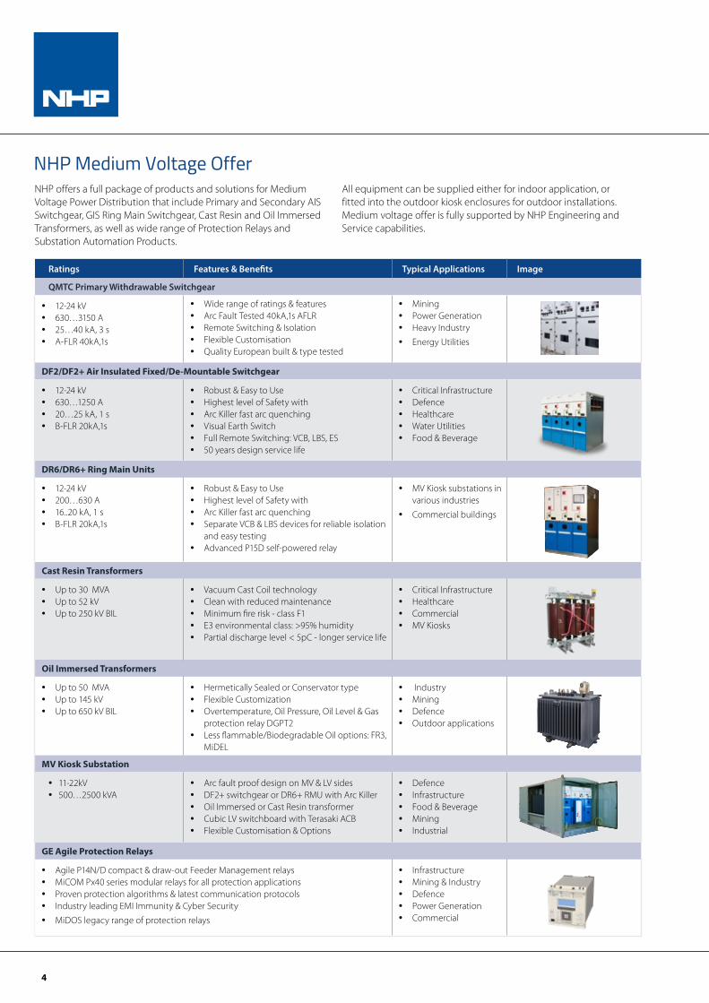
NHP Medium Voltage Offer
Ratings Features & Benefits Typical Applications Image
QMTC Primary Withdrawable Switchgear
• 12-24 kV• 630…3150 A• 25…40 kA, 3 s• A-FLR 40kA,1s
• Wide range of ratings & features• Arc Fault Tested 40kA,1s AFLR• Remote Switching & Isolation• Flexible Customisation• Quality European built & type tested
• Mining• Power Generation• Heavy Industry
• Energy Utilities
DF2/DF2+ Air Insulated Fixed/De-Mountable Switchgear
• 12-24 kV• 630…1250 A• 20…25 kA, 1 s• B-FLR 20kA,1s
• Robust & Easy to Use• Highest level of Safety with • Arc Killer fast arc quenching• Visual Earth Switch• Full Remote Switching: VCB, LBS, ES• 50 years design service life
• Critical Infrastructure• Defence• Healthcare• Water Utilities• Food & Beverage
DR6/DR6+ Ring Main Units
• 12-24 kV• 200…630 A• 16..20 kA, 1 s• B-FLR 20kA,1s
• Robust & Easy to Use• Highest level of Safety with • Arc Killer fast arc quenching• Separate VCB & LBS devices for reliable isolation
and easy testing• Advanced P15D self-powered relay
• MV Kiosk substations in various industries
• Commercial buildings
Cast Resin Transformers
• Up to 30 MVA• Up to 52 kV• Up to 250 kV BIL
• Vacuum Cast Coil technology• Clean with reduced maintenance• Minimum fire risk - class F1• E3 environmental class: >95% humidity• Partial discharge level < 5pC - longer service life
• Critical Infrastructure• Healthcare• Commercial• MV Kiosks
Oil Immersed Transformers
• Up to 50 MVA• Up to 145 kV• Up to 650 kV BIL
• Hermetically Sealed or Conservator type• Flexible Customization• Overtemperature, Oil Pressure, Oil Level & Gas
protection relay DGPT2• Less flammable/Biodegradable Oil options: FR3,
MiDEL
• Industry• Mining• Defence• Outdoor applications
MV Kiosk Substation
• 11-22kV• 500…2500 kVA
• Arc fault proof design on MV & LV sides• DF2+ switchgear or DR6+ RMU with Arc Killer• Oil Immersed or Cast Resin transformer• Cubic LV switchboard with Terasaki ACB• Flexible Customisation & Options
• Defence• Infrastructure• Food & Beverage• Mining• Industrial
GE Agile Protection Relays
• Agile P14N/D compact & draw-out Feeder Management relays • MiCOM Px40 series modular relays for all protection applications• Proven protection algorithms & latest communication protocols• Industry leading EMI Immunity & Cyber Security
• MiDOS legacy range of protection relays
• Infrastructure• Mining & Industry• Defence• Power Generation• Commercial
NHP offers a full package of products and solutions for Medium Voltage Power Distribution that include Primary and Secondary AIS Switchgear, GIS Ring Main Switchgear, Cast Resin and Oil Immersed Transformers, as well as wide range of Protection Relays and Substation Automation Products.
All equipment can be supplied either for indoor application, or fitted into the outdoor kiosk enclosures for outdoor installations. Medium voltage offer is fully supported by NHP Engineering and Service capabilities.
5
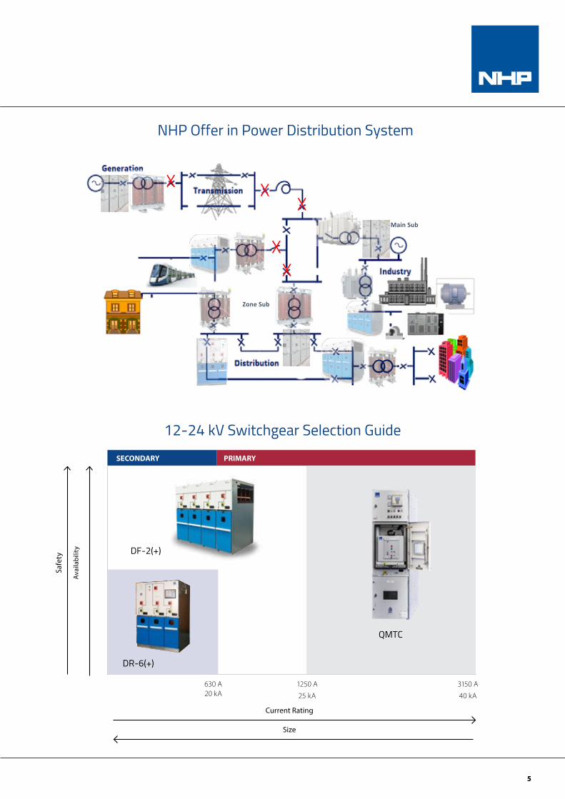
SECONDARY PRIMARY
QMTC
DF-2(+)
Current Rating
Size
Safe
ty
Avai
labi
lity
12-24 kV Switchgear Selection Guide
NHP Offer for MV Power Distribution System
XXX
XX
Zone Sub
Main Sub
Avai
labi
lity
Safe
ty
Current Rating/PriceSize
3150 A1250 A630 A
DF-2(+)
QMTC
SECONDARY PRIMARY
DR-6+
MV Switchgear Selection Chart
NHP Offer in Power Distribution System
630 A 20 kA
1250 A
25 kA
3150 A
40 kA
DR-6(+)
6
NHP experience in Medium Voltage Power DistributionNHP has been providing Medium Voltage Solutions into Australian and New Zealand markets since 2013.
Our product range have proven as robust and reliable in service, while offering advanced safety features
along with long-term reliability and maximised up-time. Product benefits combined with NHP customer-
oriented approach and service support has allowed us to establish a significant local footprint in Medium
Voltage power distribution.
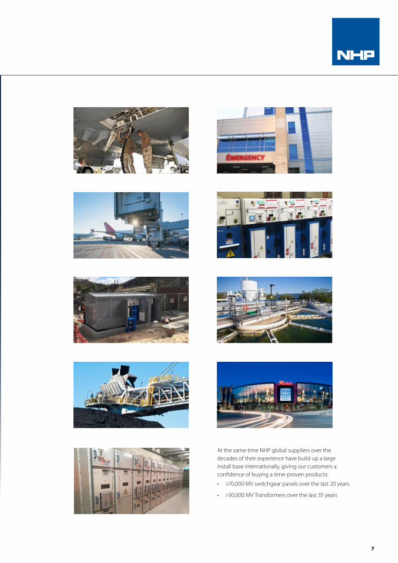
NHP MV solutions have been used in all states of Australia and in New Zealand to power a wide variety of industries and applications including:
• Australian Defence Force bases
• Hospitals, Universities and Research institutes
• Airports and Road Tunnels
• Department of Justice facilities
• Australian Antarctic Base
• Water Utilities
• Mines and Quarries
• Cement Plants
• LNG facilities
• Steel and Copper Smelters
• Shopping Centres, Hotels and Casino
• Milk & Chocolate factories
• Power Stations and Solar Farms
7
At the same time NHP global suppliers over the decades of their experience have build up a large install base internationally, giving our customers a confidence of buying a time-proven products:
• >70,000 MV switchgear panels over the last 20 years
• >30,000 MV Transformers over the last 35 years
NHP experience in Medium Voltage Power Distribution
8
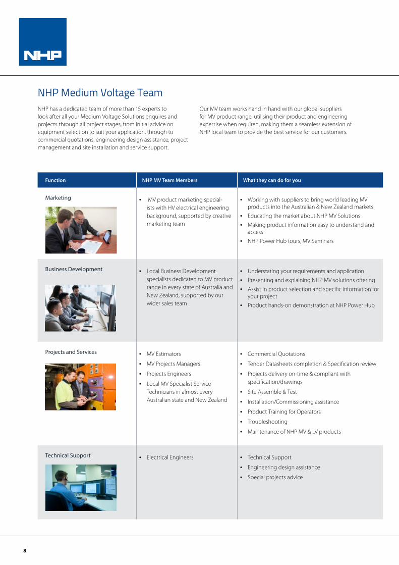
NHP Medium Voltage Team
Function NHP MV Team Members What they can do for you
Marketing • MV product marketing special-ists with HV electrical engineering background, supported by creative marketing team
• Working with suppliers to bring world leading MV products into the Australian & New Zealand markets
• Educating the market about NHP MV Solutions
• Making product information easy to understand and access
• NHP Power Hub tours, MV Seminars
Business Development • Local Business Development specialists dedicated to MV product range in every state of Australia and New Zealand, supported by our wider sales team
• Understating your requirements and application
• Presenting and explaining NHP MV solutions offering
• Assist in product selection and specific information for your project
• Product hands-on demonstration at NHP Power Hub
Projects and Services • MV Estimators
• MV Projects Managers
• Projects Engineers
• Local MV Specialist Service Technicians in almost every Australian state and New Zealand
• Commercial Quotations
• Tender Datasheets completion & Specification review
• Projects delivery on-time & compliant with specification/drawings
• Site Assemble & Test
• Installation/Commissioning assistance
• Product Training for Operators
• Troubleshooting
• Maintenance of NHP MV & LV products
Technical Support • Electrical Engineers • Technical Support
• Engineering design assistance
• Special projects advice
NHP has a dedicated team of more than 15 experts to look after all your Medium Voltage Solutions enquires and projects through all project stages, from initial advice on equipment selection to suit your application, through to commercial quotations, engineering design assistance, project management and site installation and service support.
Our MV team works hand in hand with our global suppliers for MV product range, utilising their product and engineering expertise when required, making them a seamless extension of NHP local team to provide the best service for our customers.
9
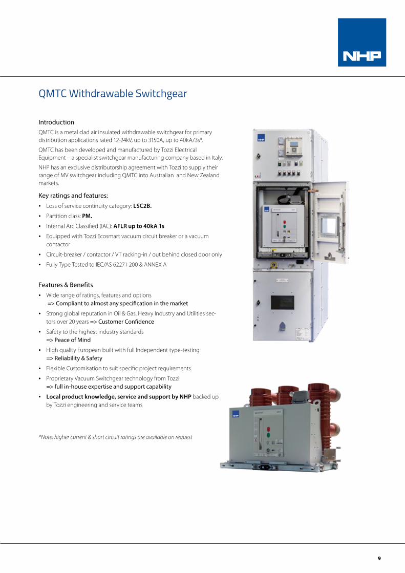
QMTC Withdrawable Switchgear
IntroductionQMTC is a metal clad air insulated withdrawable switchgear for primary distribution applications rated 12-24kV, up to 3150A, up to 40kA/3s*.
QMTC has been developed and manufactured by Tozzi Electrical Equipment – a specialist switchgear manufacturing company based in Italy.
NHP has an exclusive distributorship agreement with Tozzi to supply their range of MV switchgear including QMTC into Australian and New Zealand markets.
Key ratings and features:• Loss of service continuity category: LSC2B.
• Partition class: PM.
• Internal Arc Classified (IAC): AFLR up to 40kA 1s
• Equipped with Tozzi Ecosmart vacuum circuit breaker or a vacuum contactor
• Circuit-breaker / contactor / VT racking-in / out behind closed door only
• Fully Type Tested to IEC/AS 62271-200 & ANNEX A
Features & Benefits• Wide range of ratings, features and options
=> Compliant to almost any specification in the market
• Strong global reputation in Oil & Gas, Heavy Industry and Utilities sec-tors over 20 years => Customer Confidence
• Safety to the highest industry standards => Peace of Mind
• High quality European built with full Independent type-testing => Reliability & Safety
• Flexible Customisation to suit specific project requirements
• Proprietary Vacuum Switchgear technology from Tozzi => full in-house expertise and support capability
• Local product knowledge, service and support by NHP backed up by Tozzi engineering and service teams
*Note: higher current & short circuit ratings are available on request
10
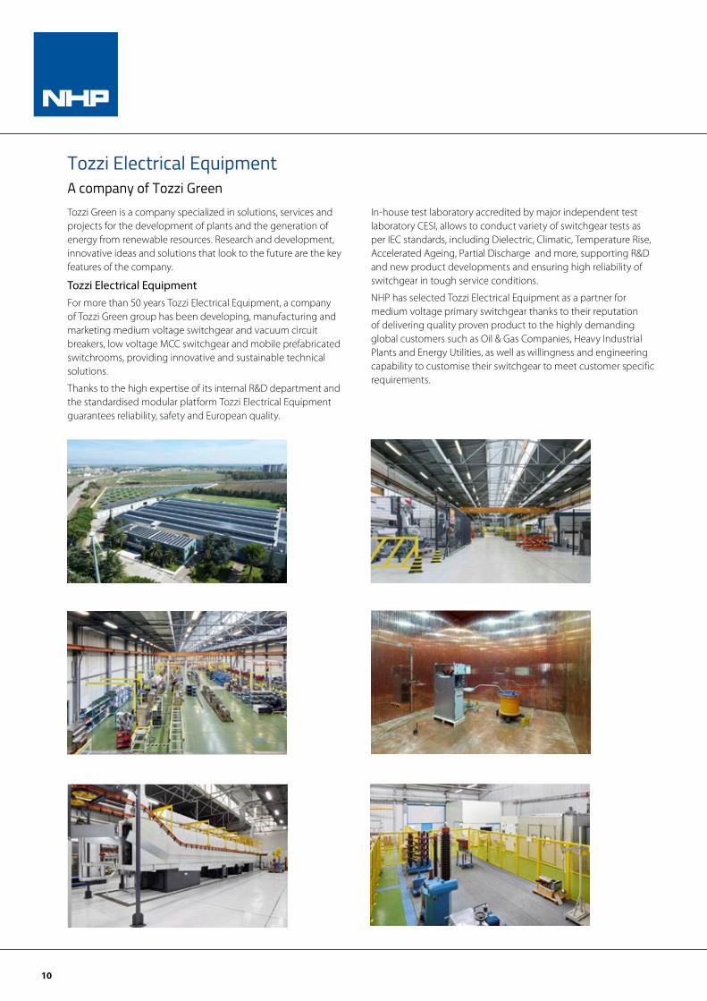
Tozzi Electrical EquipmentA company of Tozzi GreenTozzi Green is a company specialized in solutions, services and projects for the development of plants and the generation of energy from renewable resources. Research and development, innovative ideas and solutions that look to the future are the key features of the company.
Tozzi Electrical EquipmentFor more than 50 years Tozzi Electrical Equipment, a company of Tozzi Green group has been developing, manufacturing and marketing medium voltage switchgear and vacuum circuit breakers, low voltage MCC switchgear and mobile prefabricated switchrooms, providing innovative and sustainable technical solutions.
Thanks to the high expertise of its internal R&D department and the standardised modular platform Tozzi Electrical Equipment guarantees reliability, safety and European quality.
In-house test laboratory accredited by major independent test laboratory CESI, allows to conduct variety of switchgear tests as per IEC standards, including Dielectric, Climatic, Temperature Rise, Accelerated Ageing, Partial Discharge and more, supporting R&D and new product developments and ensuring high reliability of switchgear in tough service conditions.
NHP has selected Tozzi Electrical Equipment as a partner for medium voltage primary switchgear thanks to their reputation of delivering quality proven product to the highly demanding global customers such as Oil & Gas Companies, Heavy Industrial Plants and Energy Utilities, as well as willingness and engineering capability to customise their switchgear to meet customer specific requirements.
© TOZZI GREEN
Factory Overview
4
• Total Area: SQM. 38.000• Built Area: SQM. 12.500• Storage Area: SQM. 1.400• Harbour Connection: At 120 Kms (BARI)• Railway Connection: Central Railway
Station Foggia • Highway Connection: Exit Foggia
Incoronata A14 Bologna-Bari
© TOZZI GREEN
Testing Laboratory & Partial Discharge Room
28
Factory Overview
© TOZZI GREEN 30
Painting Workshop Metal Sheet Workshop
Factory OverviewMade in
Italy
© TOZZI GREEN 30
Painting Workshop Metal Sheet Workshop
Factory OverviewMade in
Italy
© TOZZI GREEN
Testing Laboratory & Partial Discharge Room
28
Factory Overview
11
Global References and Applications
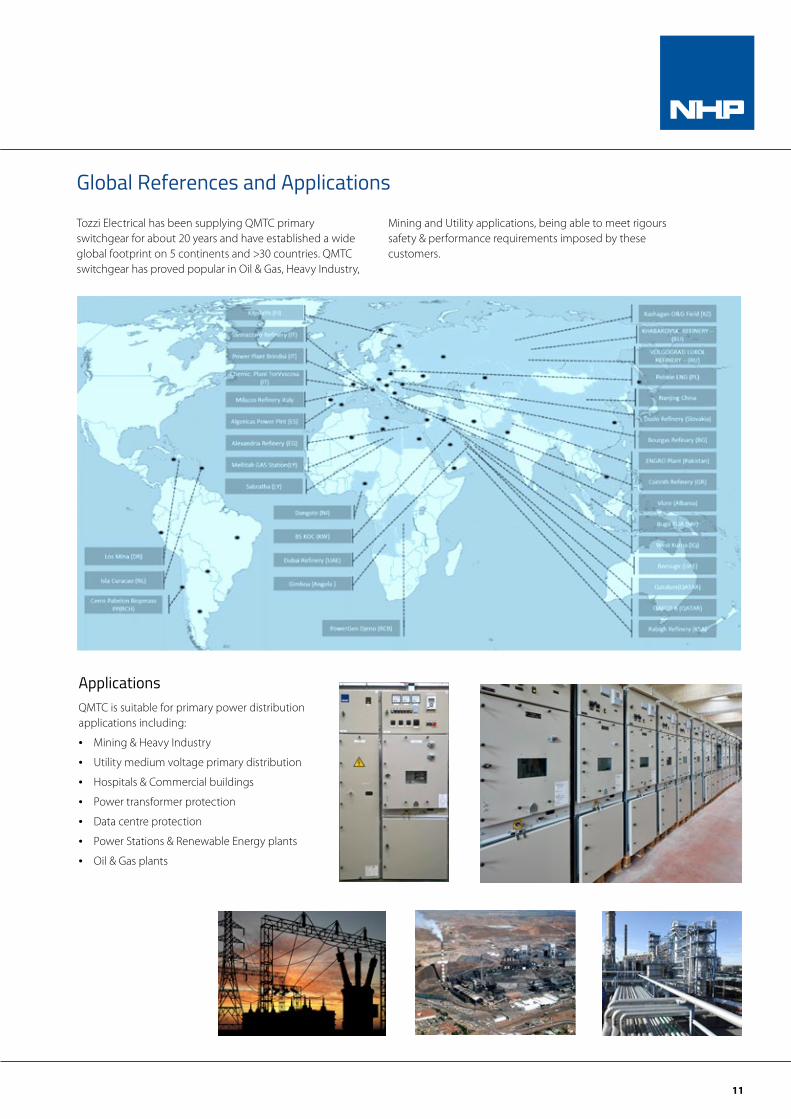
Tozzi Electrical has been supplying QMTC primary switchgear for about 20 years and have established a wide global footprint on 5 continents and >30 countries. QMTC switchgear has proved popular in Oil & Gas, Heavy Industry,
Mining and Utility applications, being able to meet rigours safety & performance requirements imposed by these customers.
ApplicationsQMTC is suitable for primary power distribution applications including:
• Mining & Heavy Industry
• Utility medium voltage primary distribution
• Hospitals & Commercial buildings
• Power transformer protection
• Data centre protection
• Power Stations & Renewable Energy plants
• Oil & Gas plants
12
Reliability and Safety They are the key attributes of QMTC series. Service continuity and long life performances are provided. People safety is a paramount. The QMTC series is fully developed and type tested according to the IEC standards 62271-200 in leading European test laboratories. QMTC has been proven in service for over 20 years in highly demanding Oil & Gas, Heavy Industry and Utility applications.
The Quality System complies with ISO 9001-100 Standards and the Health and Safety Management system complies with the OHSAS 18001:2007 standards, both certified by an independent certification body. The internal test laboratory complies with UNI CEI EN ISO/IEC 17025 with tests certified by an independent certification body.
Flexibility Modular units are available with different functions and combinations in order to satisfy the most common electrical configurations of the typical substations.
The QMTC series brings to the market a versatile switchgear ready to cover various installation requirements and market segments.
Sustainability and Environmental CareFollowing overall eco-friendly philosophy of Tozzi Green group, the QMTC series development has been driven by the environment sustainability theme.
The materials used for its production allow a very low environmental impact during the product life and most important at the end of its life cycle. The QMTC production site and the environmental management system of Tozzi Electrical Equipment complies with ISO 14001 standard.
Design Philosophy
© TOZZI GREEN 26
Environmental Management SystemISO 14001:2004
Quality Management SystemISO 9001:2008
Health & SafetyManagement SystemOHSAS 18001:2007
Certifications and TYPE TEST Laboratories
© TOZZI GREEN 26
Environmental Management SystemISO 14001:2004
Quality Management SystemISO 9001:2008
Health & SafetyManagement SystemOHSAS 18001:2007
Certifications and TYPE TEST Laboratories
© TOZZI GREEN 26
Environmental Management SystemISO 14001:2004
Quality Management SystemISO 9001:2008
Health & SafetyManagement SystemOHSAS 18001:2007
Certifications and TYPE TEST Laboratories
© TOZZI GREEN 26
Environmental Management SystemISO 14001:2004
Quality Management SystemISO 9001:2008
Health & SafetyManagement SystemOHSAS 18001:2007
Certifications and TYPE TEST Laboratories
© TOZZI GREEN 26
Environmental Management SystemISO 14001:2004
Quality Management SystemISO 9001:2008
Health & SafetyManagement SystemOHSAS 18001:2007
Certifications and TYPE TEST Laboratories
© TOZZI GREEN 26
Environmental Management SystemISO 14001:2004
Quality Management SystemISO 9001:2008
Health & SafetyManagement SystemOHSAS 18001:2007
Certifications and TYPE TEST Laboratories
© TOZZI GREEN 26
Environmental Management SystemISO 14001:2004
Quality Management SystemISO 9001:2008
Health & SafetyManagement SystemOHSAS 18001:2007
Certifications and TYPE TEST Laboratories
© TOZZI GREEN 26
Environmental Management SystemISO 14001:2004
Quality Management SystemISO 9001:2008
Health & SafetyManagement SystemOHSAS 18001:2007
Certifications and TYPE TEST Laboratories
© TOZZI GREEN 26
Environmental Management SystemISO 14001:2004
Quality Management SystemISO 9001:2008
Health & SafetyManagement SystemOHSAS 18001:2007
Certifications and TYPE TEST Laboratories
13
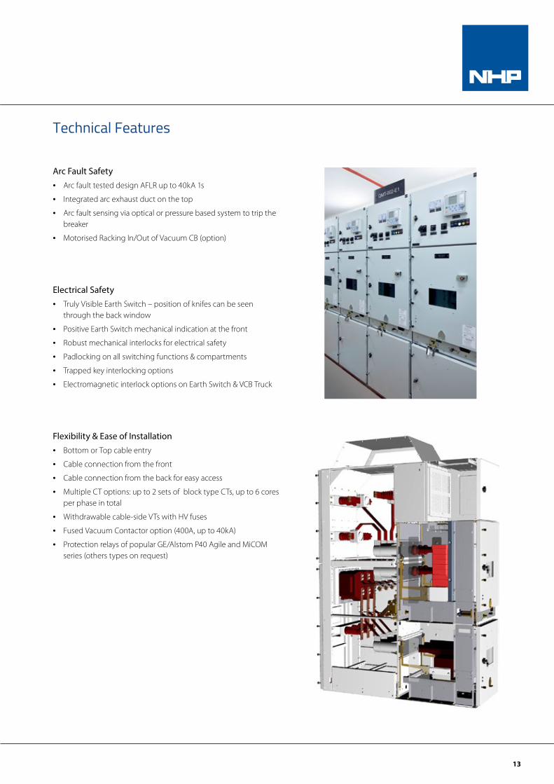
Arc Fault Safety• Arc fault tested design AFLR up to 40kA 1s
• Integrated arc exhaust duct on the top
• Arc fault sensing via optical or pressure based system to trip the breaker
• Motorised Racking In/Out of Vacuum CB (option)
Electrical Safety• Truly Visible Earth Switch – position of knifes can be seen
through the back window
• Positive Earth Switch mechanical indication at the front
• Robust mechanical interlocks for electrical safety
• Padlocking on all switching functions & compartments
• Trapped key interlocking options
• Electromagnetic interlock options on Earth Switch & VCB Truck
Flexibility & Ease of Installation• Bottom or Top cable entry
• Cable connection from the front
• Cable connection from the back for easy access
• Multiple CT options: up to 2 sets of block type CTs, up to 6 cores per phase in total
• Withdrawable cable-side VTs with HV fuses
• Fused Vacuum Contactor option (400A, up to 40kA)
• Protection relays of popular GE/Alstom P40 Agile and MiCOM series (others types on request)
Technical Features
14
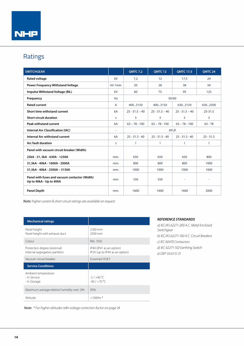
Ratings
SWITCHGEAR QMTC 7,2 QMTC 12 QMTC 17,5 QMTC 24
Rated voltage kV 7,2 12 17,5 24
Power Frequency Withstand Voltage kV 1min 20 28 38 50
Impulse Withstand Voltage (BIL) kV 60 75 95 125
Frequency Hz 50/60
Rated current A 400...3150 400...3150 630...3150 630...2500
Short time withstand current kA 25 - 31.5 – 40 25 - 31.5 – 40 25 - 31.5 – 40 25-31.5
Short circuit duration s 3 3 3 3
Peak withstand current kA 63 – 78 - 100 63 – 78 - 100 63 – 78 - 100 63 - 78
Internal Arc Classification (IAC) - AFLR
Internal Arc withstand current kA 25 - 31.5 - 40 25 - 31.5 - 40 25 - 31.5 - 40 25 - 31.5
Arc fault duration s 1 1 1 1
Panel with vacuum circuit breaker (Width)
25kA - 31, 5kA - 630A - 1250A mm. 650 650 650 800
31,5kA - 40kA - 1600A - 2000A mm. 800 800 800 1000
31,5kA - 40kA - 2500A – 3150A mm. 1000 1000 1000 1000
Panel with fuses and vacuum contactor (Width)Up to 40kA - Up to 400A
mm. 550 550 - -
Panel Depth mm. 1600 1600 1600 2000
Mechanical ratings
Panel height Panel height with exhaust duct
2200 mm2500 mm
Colour RAL 7035
Protection degree (external)Internal segregation partition
IP4X (IP41 as an option)IP2X (up to IP4X as an option)
Vacuum circuit breaker Ecosmart VCB F
Service Conditions
Ambient temperature:- In Service- In Storage
-5 / +40 °C-40 / +70 °C
Maximum average relative humidity over 24h 95%
Altitude <1000m *
REFERENCE STANDARDS
a) IEC/AS 62271-200 A.C. Metal Enclosed Switchgear
b) IEC/AS 62271-100 A.C. Circuit Breakers
c) IEC 60470 Contactors
d) IEC 62271-102 Earthing Switch
e) DEP 33.67.51.31
Note: higher current & short circuit ratings are available on request
Note: * For higher altitudes refer voltage correction factor on page 24
15
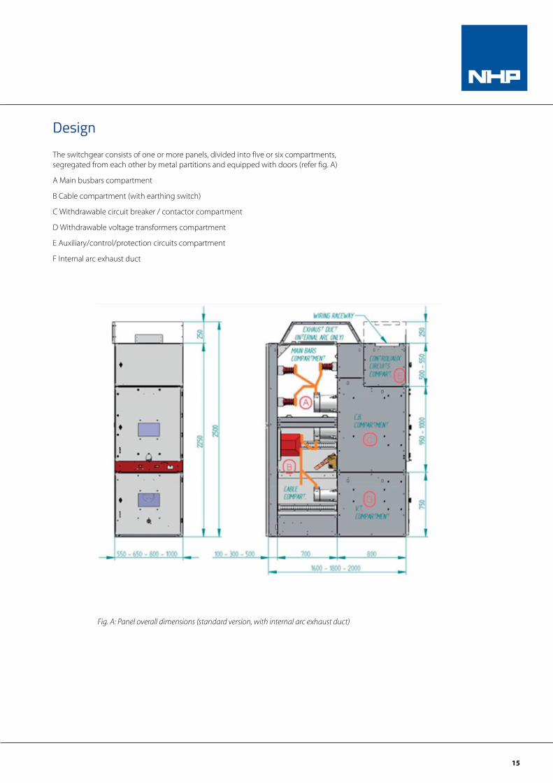
DesignThe switchgear consists of one or more panels, divided into five or six compartments, segregated from each other by metal partitions and equipped with doors (refer fig. A)
A Main busbars compartment
B Cable compartment (with earthing switch)
C Withdrawable circuit breaker / contactor compartment
D Withdrawable voltage transformers compartment
E Auxiliary/control/protection circuits compartment
F Internal arc exhaust duct
Fig. A: Panel overall dimensions (standard version, with internal arc exhaust duct)
16
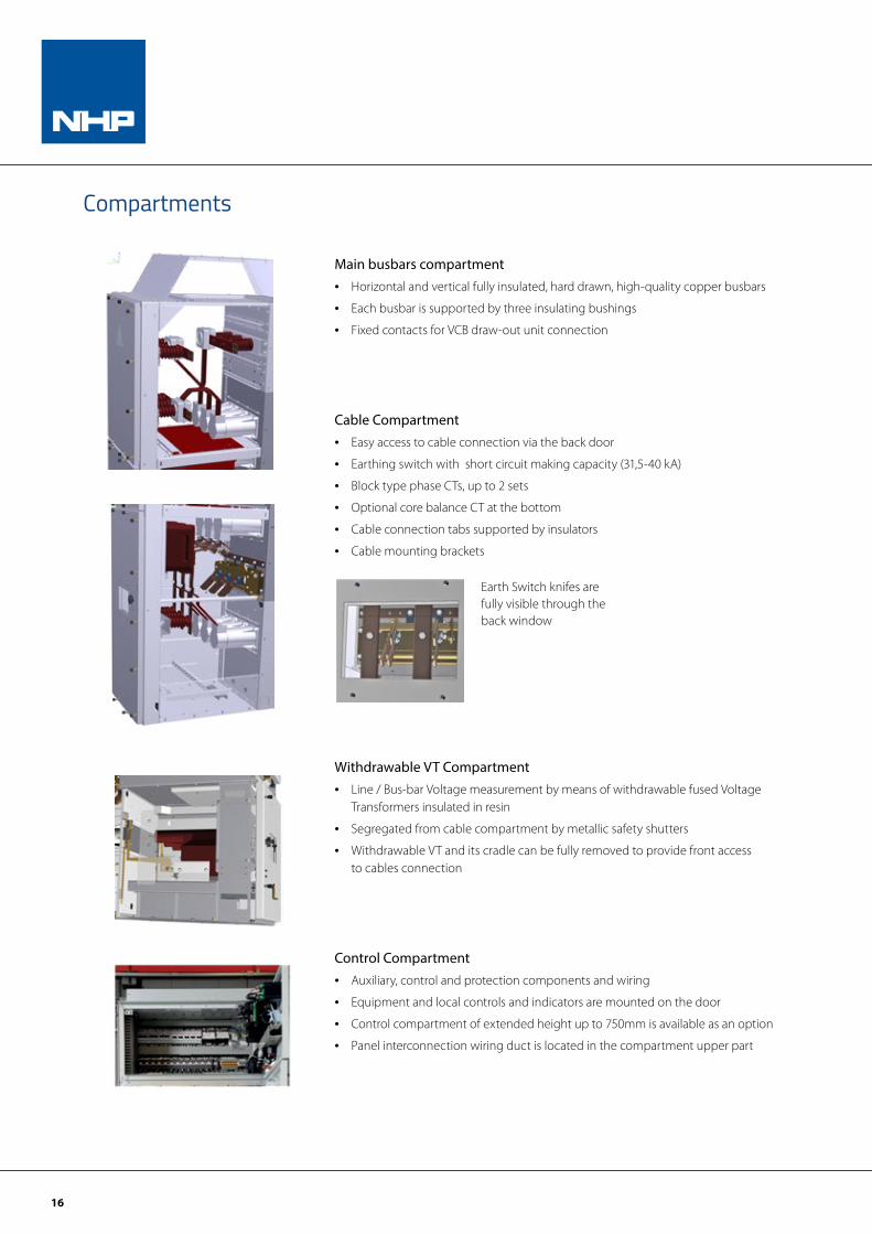
Compartments
Main busbars compartment• Horizontal and vertical fully insulated, hard drawn, high-quality copper busbars
• Each busbar is supported by three insulating bushings
• Fixed contacts for VCB draw-out unit connection
Cable Compartment• Easy access to cable connection via the back door
• Earthing switch with short circuit making capacity (31,5-40 kA)
• Block type phase CTs, up to 2 sets
• Optional core balance CT at the bottom
• Cable connection tabs supported by insulators
• Cable mounting brackets
Withdrawable VT Compartment • Line / Bus-bar Voltage measurement by means of withdrawable fused Voltage
Transformers insulated in resin
• Segregated from cable compartment by metallic safety shutters
• Withdrawable VT and its cradle can be fully removed to provide front access to cables connection
Control Compartment• Auxiliary, control and protection components and wiring
• Equipment and local controls and indicators are mounted on the door
• Control compartment of extended height up to 750mm is available as an option
• Panel interconnection wiring duct is located in the compartment upper part
Earth Switch knifes are fully visible through the back window
17
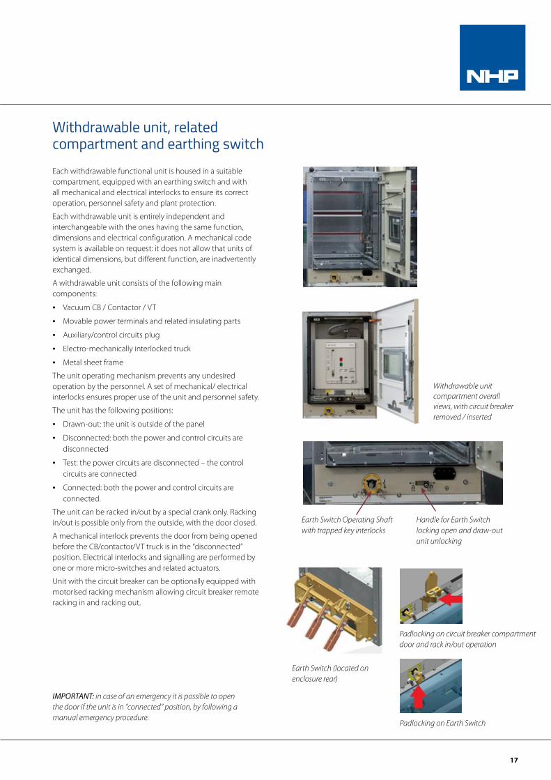
Each withdrawable functional unit is housed in a suitable compartment, equipped with an earthing switch and with all mechanical and electrical interlocks to ensure its correct operation, personnel safety and plant protection.
Each withdrawable unit is entirely independent and interchangeable with the ones having the same function, dimensions and electrical configuration. A mechanical code system is available on request: it does not allow that units of identical dimensions, but different function, are inadvertently exchanged.
A withdrawable unit consists of the following main components:
• Vacuum CB / Contactor / VT
• Movable power terminals and related insulating parts
• Auxiliary/control circuits plug
• Electro-mechanically interlocked truck
• Metal sheet frame
The unit operating mechanism prevents any undesired operation by the personnel. A set of mechanical/ electrical interlocks ensures proper use of the unit and personnel safety.
The unit has the following positions:
• Drawn-out: the unit is outside of the panel
• Disconnected: both the power and control circuits are disconnected
• Test: the power circuits are disconnected – the control circuits are connected
• Connected: both the power and control circuits are connected.
The unit can be racked in/out by a special crank only. Racking in/out is possible only from the outside, with the door closed.
A mechanical interlock prevents the door from being opened before the CB/contactor/VT truck is in the “disconnected” position. Electrical interlocks and signalling are performed by one or more micro-switches and related actuators.
Unit with the circuit breaker can be optionally equipped with motorised racking mechanism allowing circuit breaker remote racking in and racking out.
Withdrawable unit, related compartment and earthing switch
Earth Switch (located on enclosure rear)
IMPORTANT: in case of an emergency it is possible to open the door if the unit is in “connected” position, by following a manual emergency procedure.
Earth Switch Operating Shaft with trapped key interlocks
Handle for Earth Switch locking open and draw-out unit unlocking
Padlocking on Earth Switch
Padlocking on circuit breaker compartment door and rack in/out operation
Withdrawable unit compartment overall views, with circuit breaker removed / inserted
18
Withdrawable CB / contactor compartmentThis compartment is designed to house CBs/Contactors with the highest electrical performance.
The enclosure width (which determines the width of the related compartment) varies depending on the characteristics of the CB/contactor, the short-time current and the rated thermal current of the switchgear.
QMTC switchgear has four standarised enclosures of the following widths:
W = 550 mm (with contactor)
(thermal current up to 400 A, short-time current and internal arc proof up to 40 kA)
W = 650 mm (with circuit breaker)
(thermal current up to 1250 A, short-time current and internal arc proof up to 31.5 kA)
W = 800 mm (with circuit breaker)
(thermal current up to 2000 A, short-time current and internal arc proof up to 40 kA)
W = 1000 mm (with circuit breaker)
(thermal current up to 3150 A, short-time current and internal arc proof up to 40 kA).
No-load disconnecting truck (NDT)• Function 1: when installed in a special panel, it allows fur-
ther extensions of the switchgear (addition of new panels downstream) without having to de-energise the related bus-bar section.
• Function 2: when installed in a special panel, it establishes contact – with the switchgear de-energised – between the corresponding bus-bar section and the earthing bar, allowing safe maintenance operations.
Note: if the switchgear includes voltage Measuring Unit on each bus-bar section, an earthing switch installed on the corresponding V.T.s panel can be provided as an alternative to the disconnecting truck.
The truck can be compared to a permanently closed withdrawable circuit breaker.
The no-load disconnection is obtained by means of the movable power contacts that connect to the upper/lower fixed contacts of the enclosure, corresponding to the two bus-bar sections (function 1) or to a single bus-bar section and to the earthing bar (function 2). Truck and enclosure are equipped with key locks in order to prevent undesired, dangerous operations. It is provided, in addition, the mechanical coding of the related compartment fixed and movable parts.
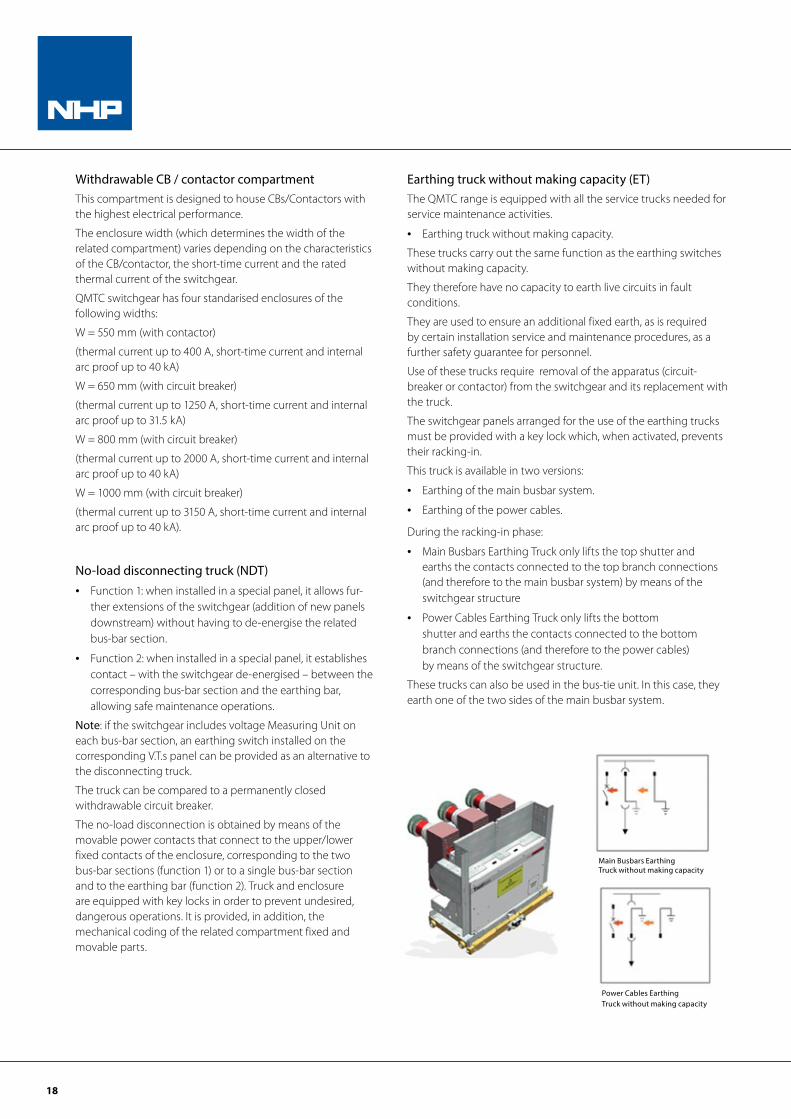
Earthing truck without making capacity (ET)The QMTC range is equipped with all the service trucks needed for service maintenance activities.
• Earthing truck without making capacity.
These trucks carry out the same function as the earthing switches without making capacity.
They therefore have no capacity to earth live circuits in fault conditions.
They are used to ensure an additional fixed earth, as is required by certain installation service and maintenance procedures, as a further safety guarantee for personnel.
Use of these trucks require removal of the apparatus (circuit-breaker or contactor) from the switchgear and its replacement with the truck.
The switchgear panels arranged for the use of the earthing trucks must be provided with a key lock which, when activated, prevents their racking-in.
This truck is available in two versions:
• Earthing of the main busbar system.
• Earthing of the power cables.
During the racking-in phase:
• Main Busbars Earthing Truck only lifts the top shutter and earths the contacts connected to the top branch connections (and therefore to the main busbar system) by means of the switchgear structure
• Power Cables Earthing Truck only lifts the bottom shutter and earths the contacts connected to the bottom branch connections (and therefore to the power cables) by means of the switchgear structure.
These trucks can also be used in the bus-tie unit. In this case, they earth one of the two sides of the main busbar system.
Power Cables Earthing Truck without making capacity
Main Busbars Earthing Truck without making capacity
19
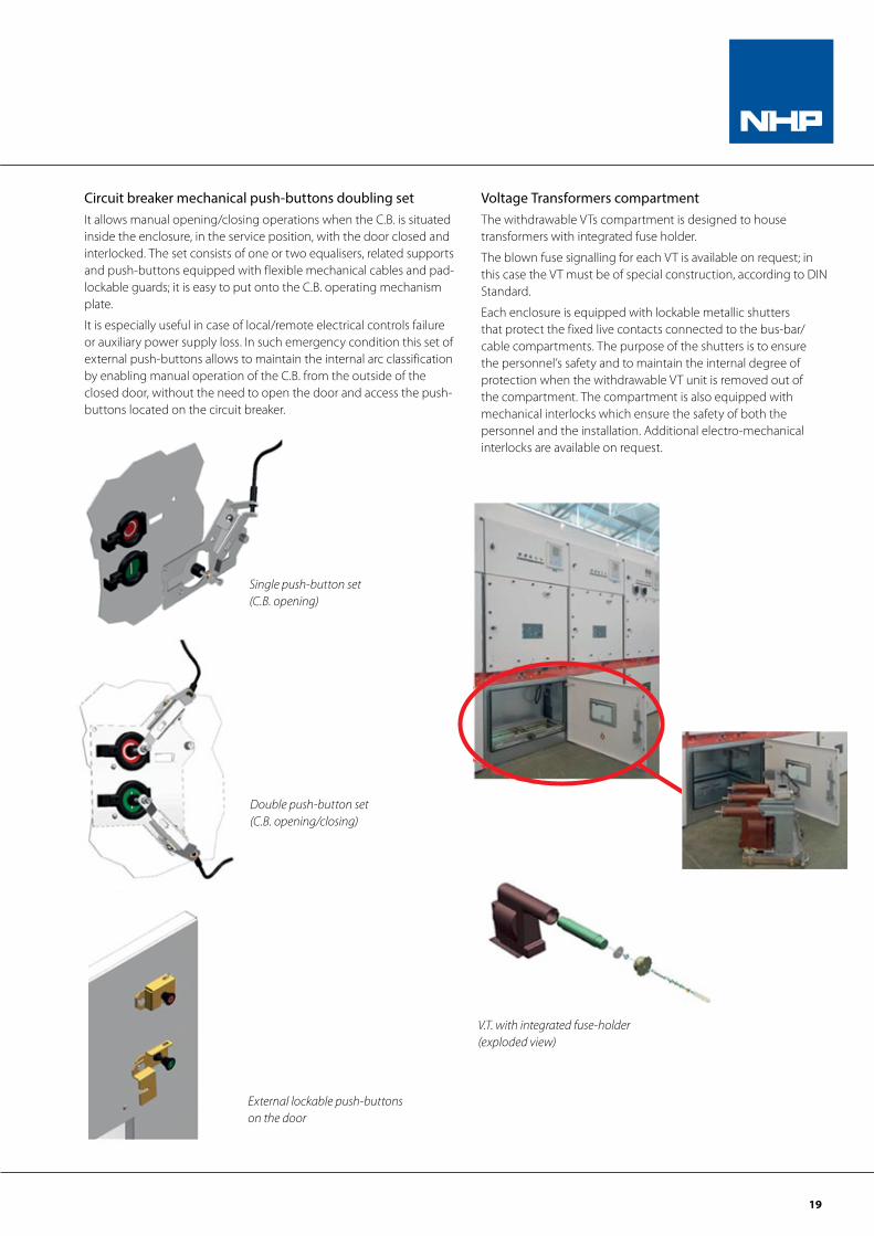
Single push-button set (C.B. opening)
Circuit breaker mechanical push-buttons doubling setIt allows manual opening/closing operations when the C.B. is situated inside the enclosure, in the service position, with the door closed and interlocked. The set consists of one or two equalisers, related supports and push-buttons equipped with flexible mechanical cables and pad-lockable guards; it is easy to put onto the C.B. operating mechanism plate.
It is especially useful in case of local/remote electrical controls failure or auxiliary power supply loss. In such emergency condition this set of external push-buttons allows to maintain the internal arc classification by enabling manual operation of the C.B. from the outside of the closed door, without the need to open the door and access the push-buttons located on the circuit breaker.
Double push-button set (C.B. opening/closing)
External lockable push-buttons on the door
Voltage Transformers compartmentThe withdrawable VTs compartment is designed to house transformers with integrated fuse holder.
The blown fuse signalling for each VT is available on request; in this case the VT must be of special construction, according to DIN Standard.
Each enclosure is equipped with lockable metallic shutters that protect the fixed live contacts connected to the bus-bar/cable compartments. The purpose of the shutters is to ensure the personnel’s safety and to maintain the internal degree of protection when the withdrawable VT unit is removed out of the compartment. The compartment is also equipped with mechanical interlocks which ensure the safety of both the personnel and the installation. Additional electro-mechanical interlocks are available on request.
V.T. with integrated fuse-holder (exploded view)
20
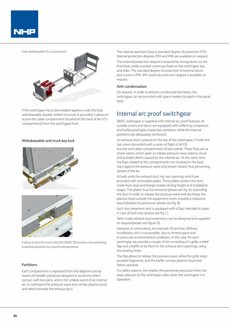
It allows to lock the truck in the DISCONNECTED position, thus preventing undesired operations by unauthorised personnel.
Withdrawable unit truck key lock
Fully withdrawable V.T.s compartment
If the switchgear has to be installed against a wall, this fully withdrawable, double-nested structure is provided; it allows to access the cable compartment (located at the back of the V.T.s compartment) from the switchgear front.
Partitions
Each compartment is separated from the adjacent one by means of metallic partitions designed to avoid any direct contact with live parts, and in the unlikely event of an internal arc, to withstand the pressure wave and convey plasma cloud and debris towards the exhaust duct.
The internal partitions have a standard degree of protection IP2X. Internal protection degrees IP3X and IP4X are available on request.
The external protection degree is ensured by strong doors on the front/rear, while screwed covers are fixed on the switchgear top and sides. The standard degree of protection of external doors and covers is IP4X. IP41 external protection degree is available on request.
Anti-condensationOn request, in order to prevent condensate formation, the switchgear can be provided with space heaters located in the panel base.
Internal arc proof switchgearQMTC switchgear is supplied with internal arc proof features: all outside covers and doors are equipped with stiffening crosspieces and bullet-proof glass inspection windows, while the internal partitions are adequately reinforced.
An exhaust duct is placed on the top of the switchgear; it holds the top covers (provided with a series of flaps) of all CB, bus-bar and cable compartments of each panel. These flaps act as check valves, which open to release pressure wave, plasma cloud and possible debris caused by the internal arc. At the same time, the flaps related to the compartments not involved in the fault, react against the pressure wave and remain closed, thus preventing spread of the arc.
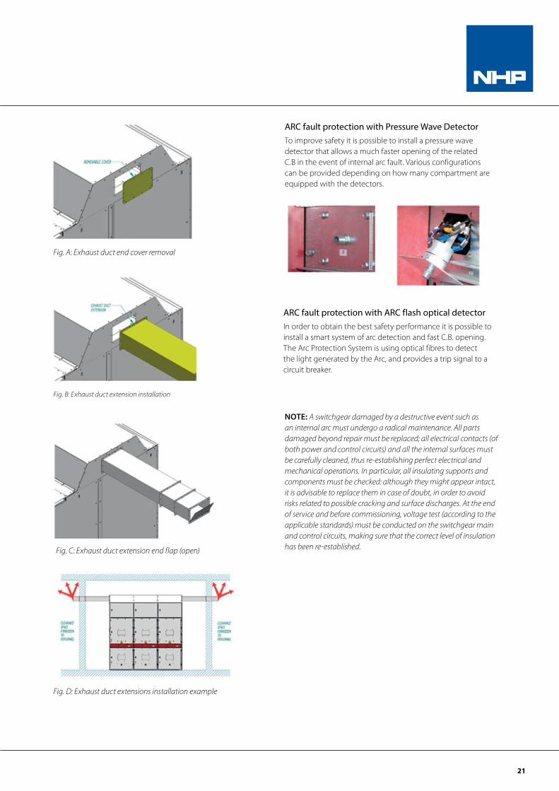
At both ends the exhaust duct has two openings which are provided with removable plates. These plates protect the duct inside from dust and foreign bodies during freight and installation stages. The plates must be removed (please see fig. A), extending the duct in order to release the pressure wave and discharge the plasma cloud outside the equipment room, towards a clearance area forbidden to personnel (please see fig. B).
Each duct extension end is equipped with a flap, intended to open in case of fault only (please see fig. C).
Tailor made exhaust duct extensions can be designed and supplied on request(please see figure D).
However, in some plants, for example Oil and Gas offshore installations, this is not possible, due to limited space and or particular environmental conditions. In this case, for each switchgear we provide a couple of kits consisting of a grille, a relief flap and a baffle to be fixed on the exhaust duct openings, using the existing holes.
The flap allows to release the pressure wave, while the grille stops possible fragments, and the baffle conveys plasma cloud and debris upwards.
For safety reasons, this implies the personnel preclusion from the areas adjacent to the switchgear sides when the switchgear is in operation.
21
ARC fault protection with Pressure Wave DetectorTo improve safety it is possible to install a pressure wave detector that allows a much faster opening of the related C.B in the event of internal arc fault. Various configurations can be provided depending on how many compartment are equipped with the detectors.
ARC fault protection with ARC flash optical detectorIn order to obtain the best safety performance it is possible to install a smart system of arc detection and fast C.B. opening. The Arc Protection System is using optical fibres to detect the light generated by the Arc, and provides a trip signal to a circuit breaker.
NOTE: A switchgear damaged by a destructive event such as an internal arc must undergo a radical maintenance. All parts damaged beyond repair must be replaced; all electrical contacts (of both power and control circuits) and all the internal surfaces must be carefully cleaned, thus re-establishing perfect electrical and mechanical operations. In particular, all insulating supports and components must be checked: although they might appear intact, it is advisable to replace them in case of doubt, in order to avoid risks related to possible cracking and surface discharges. At the end of service and before commissioning, voltage test (according to the applicable standards) must be conducted on the switchgear main and control circuits, making sure that the correct level of insulation has been re-established.
Fig. A: Exhaust duct end cover removal
Fig. B: Exhaust duct extension installation
Fig. C: Exhaust duct extension end flap (open)
Fig. D: Exhaust duct extensions installation example
22
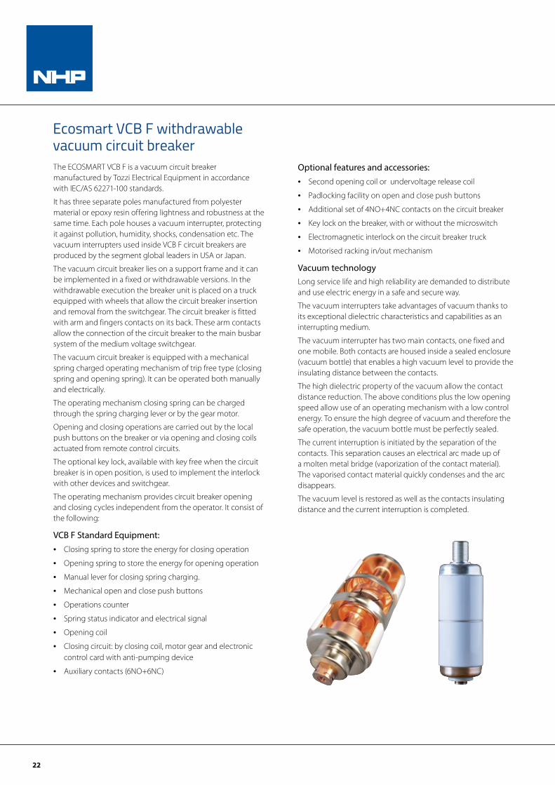
Ecosmart VCB F withdrawable vacuum circuit breakerThe ECOSMART VCB F is a vacuum circuit breaker manufactured by Tozzi Electrical Equipment in accordance with IEC/AS 62271-100 standards.
It has three separate poles manufactured from polyester material or epoxy resin offering lightness and robustness at the same time. Each pole houses a vacuum interrupter, protecting it against pollution, humidity, shocks, condensation etc. The vacuum interrupters used inside VCB F circuit breakers are produced by the segment global leaders in USA or Japan.
The vacuum circuit breaker lies on a support frame and it can be implemented in a fixed or withdrawable versions. In the withdrawable execution the breaker unit is placed on a truck equipped with wheels that allow the circuit breaker insertion and removal from the switchgear. The circuit breaker is fitted with arm and fingers contacts on its back. These arm contacts allow the connection of the circuit breaker to the main busbar system of the medium voltage switchgear.
The vacuum circuit breaker is equipped with a mechanical spring charged operating mechanism of trip free type (closing spring and opening spring). It can be operated both manually and electrically.
The operating mechanism closing spring can be charged through the spring charging lever or by the gear motor.
Opening and closing operations are carried out by the local push buttons on the breaker or via opening and closing coils actuated from remote control circuits.
The optional key lock, available with key free when the circuit breaker is in open position, is used to implement the interlock with other devices and switchgear.
The operating mechanism provides circuit breaker opening and closing cycles independent from the operator. It consist of the following:
VCB F Standard Equipment:• Closing spring to store the energy for closing operation
• Opening spring to store the energy for opening operation
• Manual lever for closing spring charging.
• Mechanical open and close push buttons
• Operations counter
• Spring status indicator and electrical signal
• Opening coil
• Closing circuit: by closing coil, motor gear and electronic control card with anti-pumping device
• Auxiliary contacts (6NO+6NC)
Optional features and accessories:• Second opening coil or undervoltage release coil
• Padlocking facility on open and close push buttons
• Additional set of 4NO+4NC contacts on the circuit breaker
• Key lock on the breaker, with or without the microswitch
• Electromagnetic interlock on the circuit breaker truck
• Motorised racking in/out mechanism
Vacuum technologyLong service life and high reliability are demanded to distribute and use electric energy in a safe and secure way.
The vacuum interrupters take advantages of vacuum thanks to its exceptional dielectric characteristics and capabilities as an interrupting medium.
The vacuum interrupter has two main contacts, one fixed and one mobile. Both contacts are housed inside a sealed enclosure (vacuum bottle) that enables a high vacuum level to provide the insulating distance between the contacts.
The high dielectric property of the vacuum allow the contact distance reduction. The above conditions plus the low opening speed allow use of an operating mechanism with a low control energy. To ensure the high degree of vacuum and therefore the safe operation, the vacuum bottle must be perfectly sealed.
The current interruption is initiated by the separation of the contacts. This separation causes an electrical arc made up of a molten metal bridge (vaporization of the contact material). The vaporised contact material quickly condenses and the arc disappears.
The vacuum level is restored as well as the contacts insulating distance and the current interruption is completed.
23
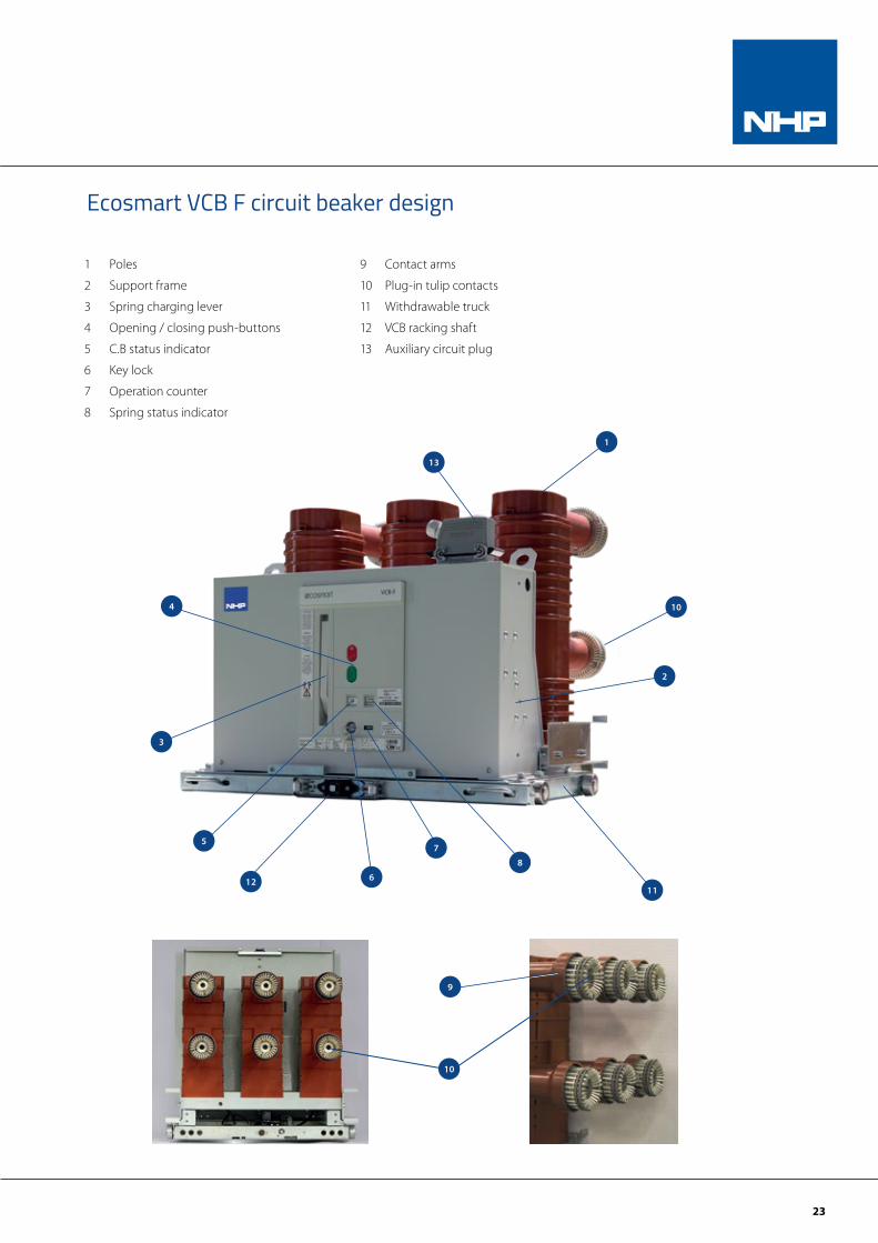
1 Poles
2 Support frame
3 Spring charging lever
4 Opening / closing push-buttons
5 C.B status indicator
6 Key lock
7 Operation counter
8 Spring status indicator
1
2
4
75
3
6
8
9 Contact arms
10 Plug-in tulip contacts
11 Withdrawable truck
12 VCB racking shaft
13 Auxiliary circuit plug
10
1112
13
Ecosmart VCB F circuit beaker design
10
9
24
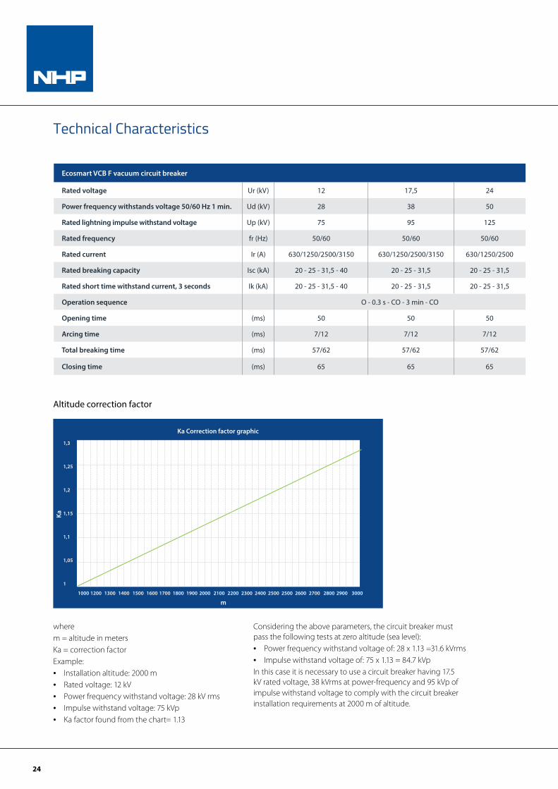
Technical Characteristics
Ecosmart VCB F vacuum circuit breaker
Rated voltage Ur (kV) 12 17,5 24
Power frequency withstands voltage 50/60 Hz 1 min. Ud (kV) 28 38 50
Rated lightning impulse withstand voltage Up (kV) 75 95 125
Rated frequency fr (Hz) 50/60 50/60 50/60
Rated current Ir (A) 630/1250/2500/3150 630/1250/2500/3150 630/1250/2500
Rated breaking capacity Isc (kA) 20 - 25 - 31,5 - 40 20 - 25 - 31,5 20 - 25 - 31,5
Rated short time withstand current, 3 seconds Ik (kA) 20 - 25 - 31,5 - 40 20 - 25 - 31,5 20 - 25 - 31,5
Operation sequence O - 0.3 s - CO - 3 min - CO
Opening time (ms) 50 50 50
Arcing time (ms) 7/12 7/12 7/12
Total breaking time (ms) 57/62 57/62 57/62
Closing time (ms) 65 65 65
Altitude correction factor
FATTORE DI CORREZIONE DELL’ALTITUDINEALTITUDE CORRECTION FACTOR
1,3
1,25
1,2
1,15
1,1
1,05
1
Ka Correction factor graphic
m
Ka
1000 1200 1300 1400 1500 1600 1700 1800 1900 2000 2100 2200 2300 2400 2500 2500 2600 2700 2800 2900 3000
wherem = altitude in metersKa = correction factorExample:• Installation altitude: 2000 m• Rated voltage: 12 kV• Power frequency withstand voltage: 28 kV rms• Impulse withstand voltage: 75 kVp• Ka factor found from the chart= 1.13
Considering the above parameters, the circuit breaker must pass the following tests at zero altitude (sea level):• Power frequency withstand voltage of: 28 x 1.13 =31.6 kVrms• Impulse withstand voltage of: 75 x 1.13 = 84.7 kVpIn this case it is necessary to use a circuit breaker having 17.5 kV rated voltage, 38 kVrms at power-frequency and 95 kVp of impulse withstand voltage to comply with the circuit breaker installation requirements at 2000 m of altitude.
25
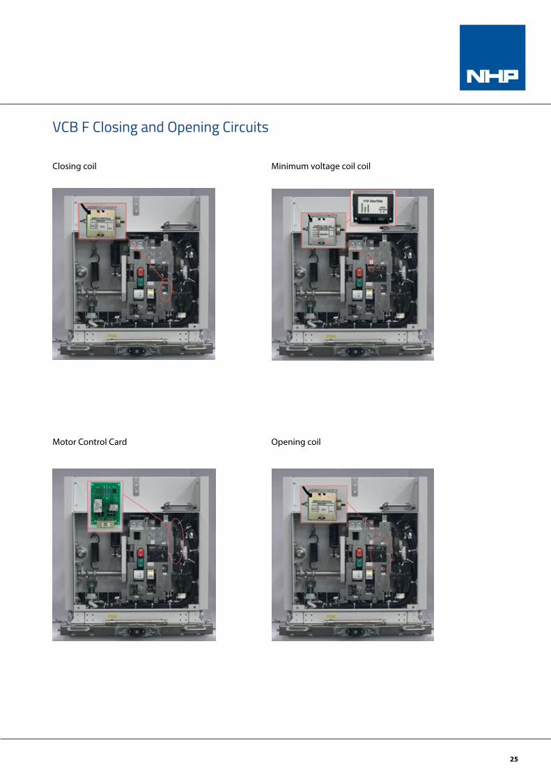
Closing coil Minimum voltage coil coil
Motor Control Card Opening coil
VCB F Closing and Opening Circuits
26
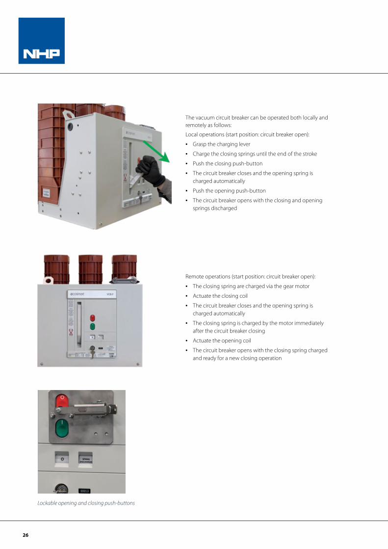
The vacuum circuit breaker can be operated both locally and remotely as follows:
Local operations (start position: circuit breaker open):
• Grasp the charging lever
• Charge the closing springs until the end of the stroke
• Push the closing push-button
• The circuit breaker closes and the opening spring is charged automatically
• Push the opening push-button
• The circuit breaker opens with the closing and opening springs discharged
Lockable opening and closing push-buttons
Remote operations (start position: circuit breaker open):
• The closing spring are charged via the gear motor
• Actuate the closing coil
• The circuit breaker closes and the opening spring is charged automatically
• The closing spring is charged by the motor immediately after the circuit breaker closing
• Actuate the opening coil
• The circuit breaker opens with the closing spring charged and ready for a new closing operation
27
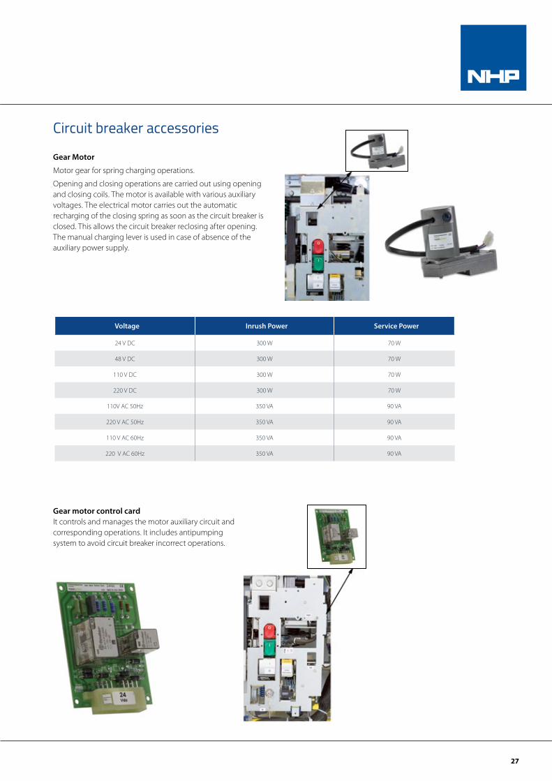
Gear Motor
Motor gear for spring charging operations.
Opening and closing operations are carried out using opening and closing coils. The motor is available with various auxiliary voltages. The electrical motor carries out the automatic recharging of the closing spring as soon as the circuit breaker is closed. This allows the circuit breaker reclosing after opening. The manual charging lever is used in case of absence of the auxiliary power supply.
Circuit breaker accessories
Voltage Inrush Power Service Power
24 V DC 300 W 70 W
48 V DC 300 W 70 W
110 V DC 300 W 70 W
220 V DC 300 W 70 W
110V AC 50Hz 350 VA 90 VA
220 V AC 50Hz 350 VA 90 VA
110 V AC 60Hz 350 VA 90 VA
220 V AC 60Hz 350 VA 90 VA
Gear motor control cardIt controls and manages the motor auxiliary circuit and corresponding operations. It includes antipumping system to avoid circuit breaker incorrect operations.
28
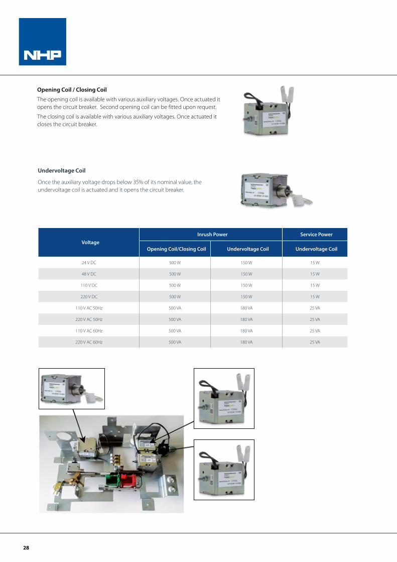
Opening Coil / Closing Coil
The opening coil is available with various auxiliary voltages. Once actuated it opens the circuit breaker. Second opening coil can be fitted upon request.
The closing coil is available with various auxiliary voltages. Once actuated it closes the circuit breaker.
VoltageInrush Power Service Power
Opening Coil/Closing Coil Undervoltage Coil Undervoltage Coil
24 V DC 500 W 150 W 15 W
48 V DC 500 W 150 W 15 W
110 V DC 500 W 150 W 15 W
220 V DC 500 W 150 W 15 W
110 V AC 50Hz 500 VA 180 VA 25 VA
220 V AC 50Hz 500 VA 180 VA 25 VA
110 V AC 60Hz 500 VA 180 VA 25 VA
220 V AC 60Hz 500 VA 180 VA 25 VA
Undervoltage Coil
Once the auxiliary voltage drops below 35% of its nominal value, the undervoltage coil is actuated and it opens the circuit breaker.
29
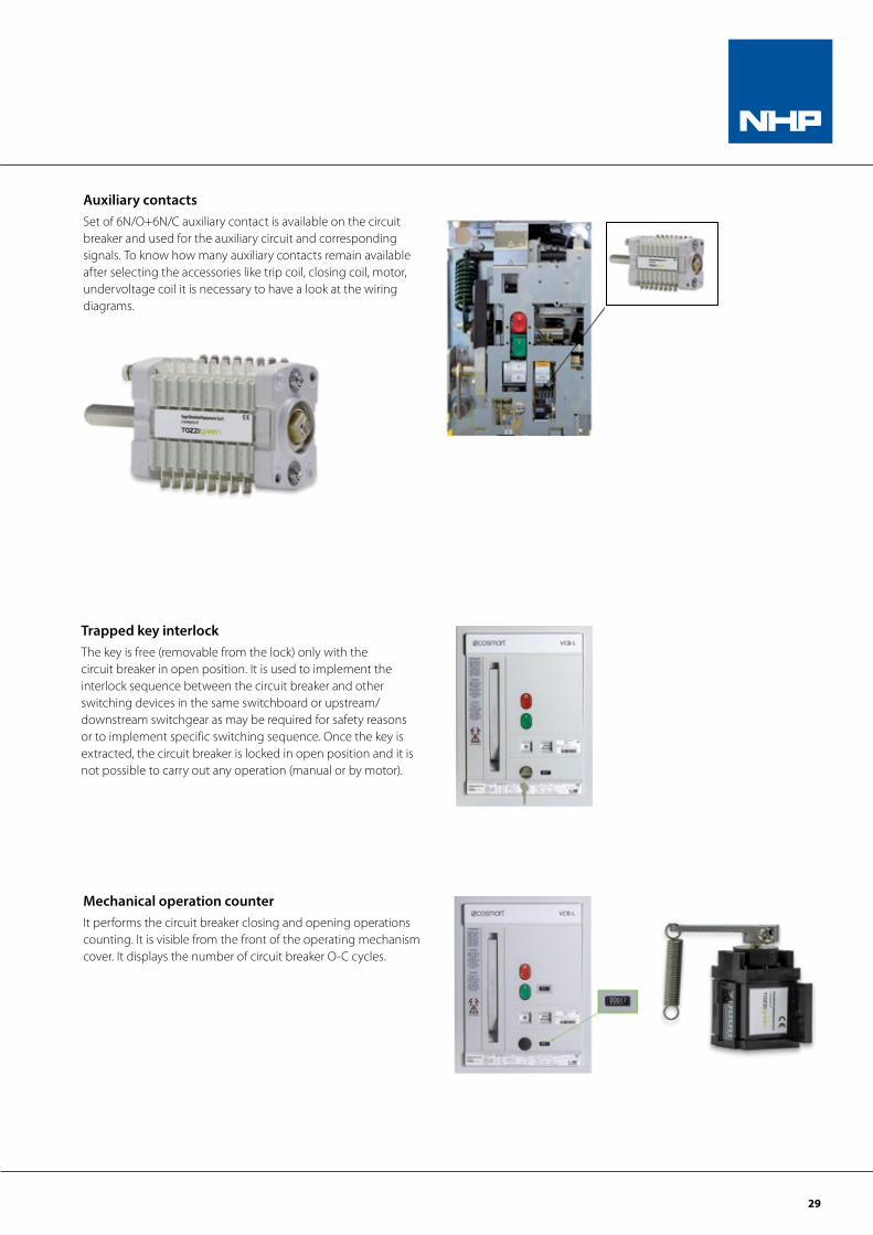
Auxiliary contactsSet of 6N/O+6N/C auxiliary contact is available on the circuit breaker and used for the auxiliary circuit and corresponding signals. To know how many auxiliary contacts remain available after selecting the accessories like trip coil, closing coil, motor, undervoltage coil it is necessary to have a look at the wiring diagrams.
Trapped key interlockThe key is free (removable from the lock) only with the circuit breaker in open position. It is used to implement the interlock sequence between the circuit breaker and other switching devices in the same switchboard or upstream/downstream switchgear as may be required for safety reasons or to implement specific switching sequence. Once the key is extracted, the circuit breaker is locked in open position and it is not possible to carry out any operation (manual or by motor).
Mechanical operation counterIt performs the circuit breaker closing and opening operations counting. It is visible from the front of the operating mechanism cover. It displays the number of circuit breaker O-C cycles.
30
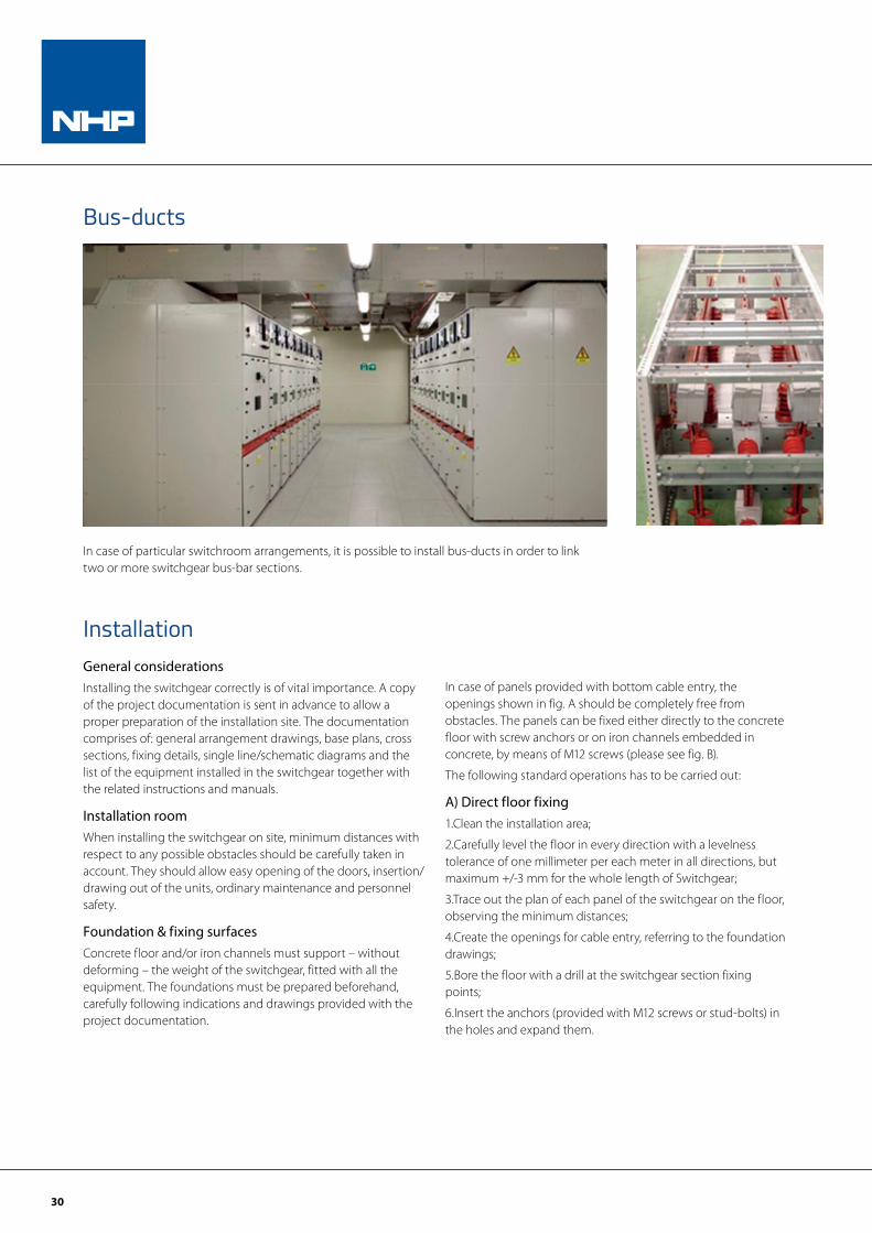
In case of particular switchroom arrangements, it is possible to install bus-ducts in order to link two or more switchgear bus-bar sections.
InstallationGeneral considerationsInstalling the switchgear correctly is of vital importance. A copy of the project documentation is sent in advance to allow a proper preparation of the installation site. The documentation comprises of: general arrangement drawings, base plans, cross sections, fixing details, single line/schematic diagrams and the list of the equipment installed in the switchgear together with the related instructions and manuals.
Installation roomWhen installing the switchgear on site, minimum distances with respect to any possible obstacles should be carefully taken in account. They should allow easy opening of the doors, insertion/drawing out of the units, ordinary maintenance and personnel safety.
Foundation & fixing surfacesConcrete floor and/or iron channels must support – without deforming – the weight of the switchgear, fitted with all the equipment. The foundations must be prepared beforehand, carefully following indications and drawings provided with the project documentation.
In case of panels provided with bottom cable entry, the openings shown in fig. A should be completely free from obstacles. The panels can be fixed either directly to the concrete floor with screw anchors or on iron channels embedded in concrete, by means of M12 screws (please see fig. B).
The following standard operations has to be carried out:
A) Direct floor fixing1.Clean the installation area;
2.Carefully level the floor in every direction with a levelness tolerance of one millimeter per each meter in all directions, but maximum +/-3 mm for the whole length of Switchgear;
3.Trace out the plan of each panel of the switchgear on the floor, observing the minimum distances;
4.Create the openings for cable entry, referring to the foundation drawings;
5.Bore the floor with a drill at the switchgear section fixing points;
6.Insert the anchors (provided with M12 screws or stud-bolts) in the holes and expand them.
Bus-ducts
31
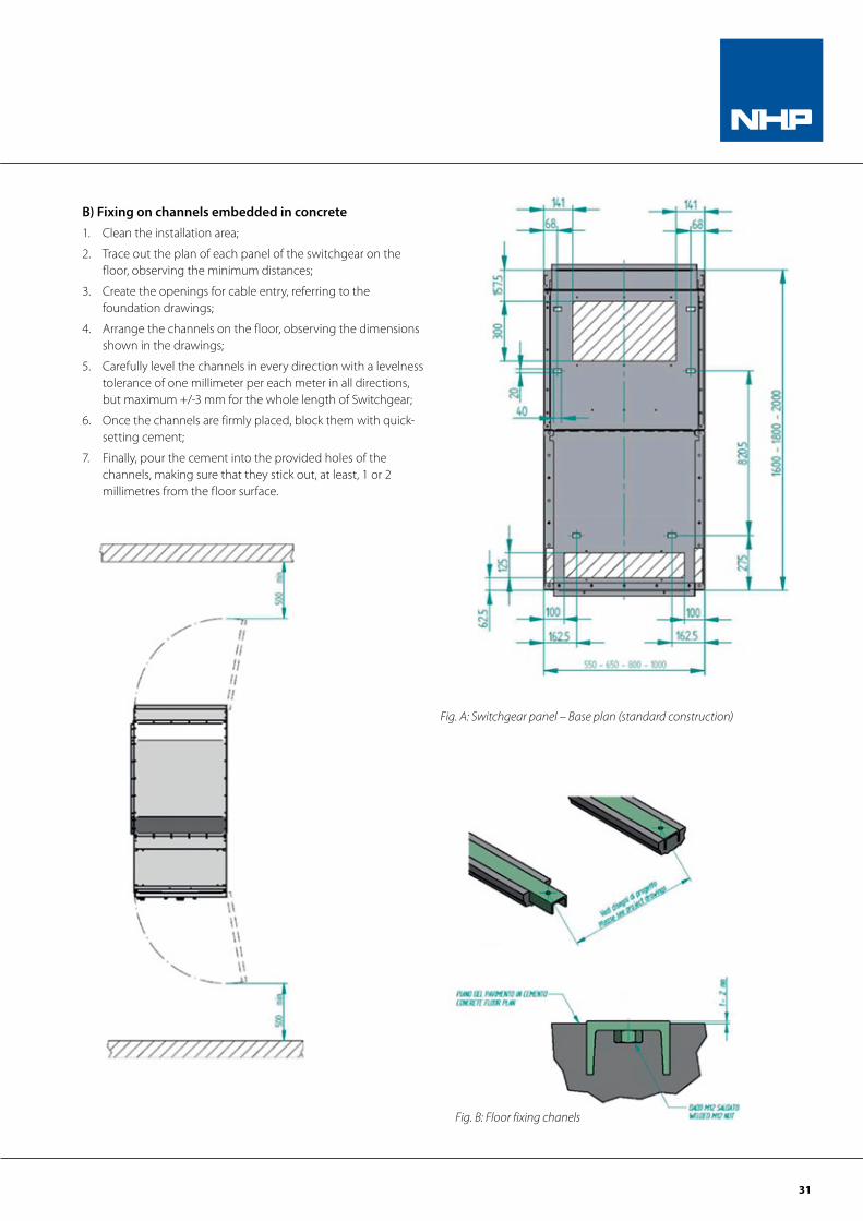
B) Fixing on channels embedded in concrete1. Clean the installation area;
2. Trace out the plan of each panel of the switchgear on the floor, observing the minimum distances;
3. Create the openings for cable entry, referring to the foundation drawings;
4. Arrange the channels on the floor, observing the dimensions shown in the drawings;
5. Carefully level the channels in every direction with a levelness tolerance of one millimeter per each meter in all directions, but maximum +/-3 mm for the whole length of Switchgear;
6. Once the channels are firmly placed, block them with quick- setting cement;
7. Finally, pour the cement into the provided holes of the channels, making sure that they stick out, at least, 1 or 2 millimetres from the floor surface.
Fig. A: Switchgear panel – Base plan (standard construction)
Fig. B: Floor fixing chanels
32
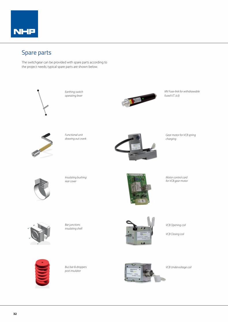
Spare partsThe switchgear can be provided with spare parts according to the project needs; typical spare parts are shown below.
Functional unit drawing out crank
Earthing switchoperating lever
Bus bar & droppers post insulator
Insulating bushing rear cover
Bar junctions insulating shell
Gear motor for VCB spring charging
Motor control card for VCB gear motor
VCB Opening coil
VCB Closing coil
VCB Undervoltage coil
MV Fuse-link for withdrawable fused V.T. (x3)
33
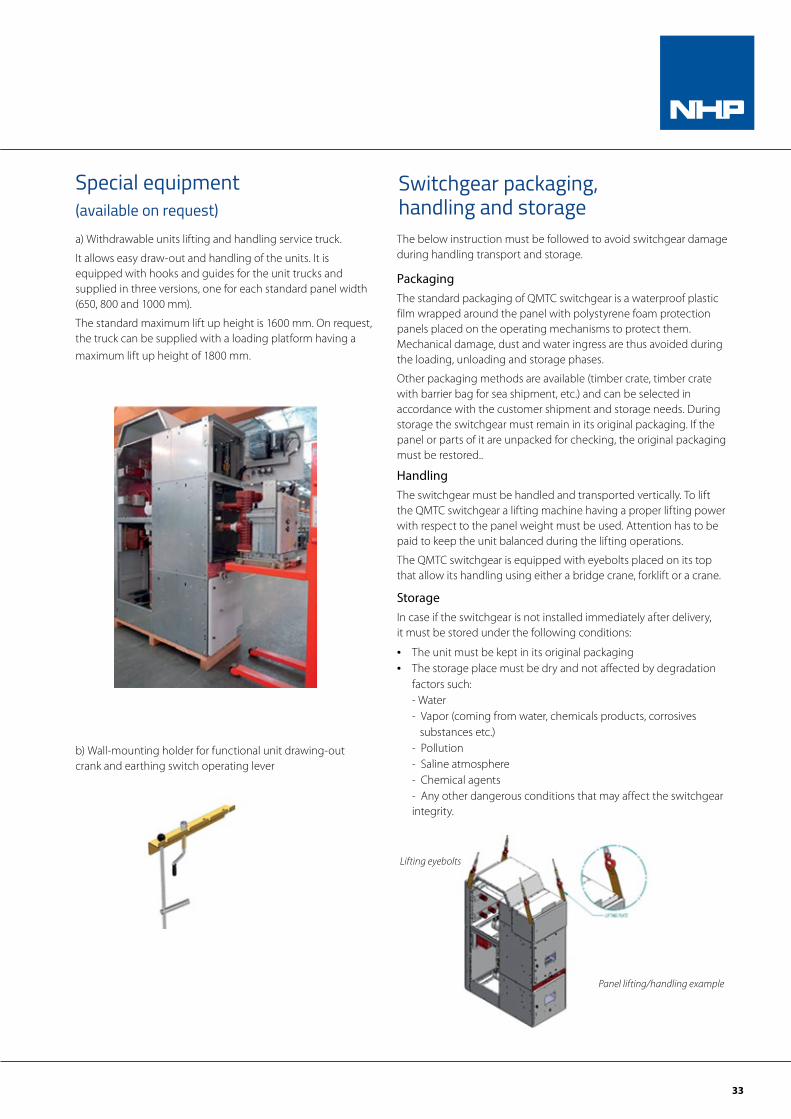
Special equipment(available on request)a) Withdrawable units lifting and handling service truck.
It allows easy draw-out and handling of the units. It is equipped with hooks and guides for the unit trucks and supplied in three versions, one for each standard panel width (650, 800 and 1000 mm).
The standard maximum lift up height is 1600 mm. On request, the truck can be supplied with a loading platform having a maximum lift up height of 1800 mm.
b) Wall-mounting holder for functional unit drawing-out crank and earthing switch operating lever
The below instruction must be followed to avoid switchgear damage during handling transport and storage.
PackagingThe standard packaging of QMTC switchgear is a waterproof plastic film wrapped around the panel with polystyrene foam protection panels placed on the operating mechanisms to protect them.Mechanical damage, dust and water ingress are thus avoided during the loading, unloading and storage phases.
Other packaging methods are available (timber crate, timber crate with barrier bag for sea shipment, etc.) and can be selected inaccordance with the customer shipment and storage needs. Duringstorage the switchgear must remain in its original packaging. If thepanel or parts of it are unpacked for checking, the original packagingmust be restored..
HandlingThe switchgear must be handled and transported vertically. To lift the QMTC switchgear a lifting machine having a proper lifting power with respect to the panel weight must be used. Attention has to be paid to keep the unit balanced during the lifting operations.
The QMTC switchgear is equipped with eyebolts placed on its top that allow its handling using either a bridge crane, forklift or a crane.
StorageIn case if the switchgear is not installed immediately after delivery, it must be stored under the following conditions:
• The unit must be kept in its original packaging• The storage place must be dry and not affected by degradation
factors such: - Water - Vapor (coming from water, chemicals products, corrosives substances etc.) - Pollution - Saline atmosphere - Chemical agents - Any other dangerous conditions that may affect the switchgear integrity.
Panel lifting/handling example
Lifting eyebolts
Switchgear packaging, handling and storage
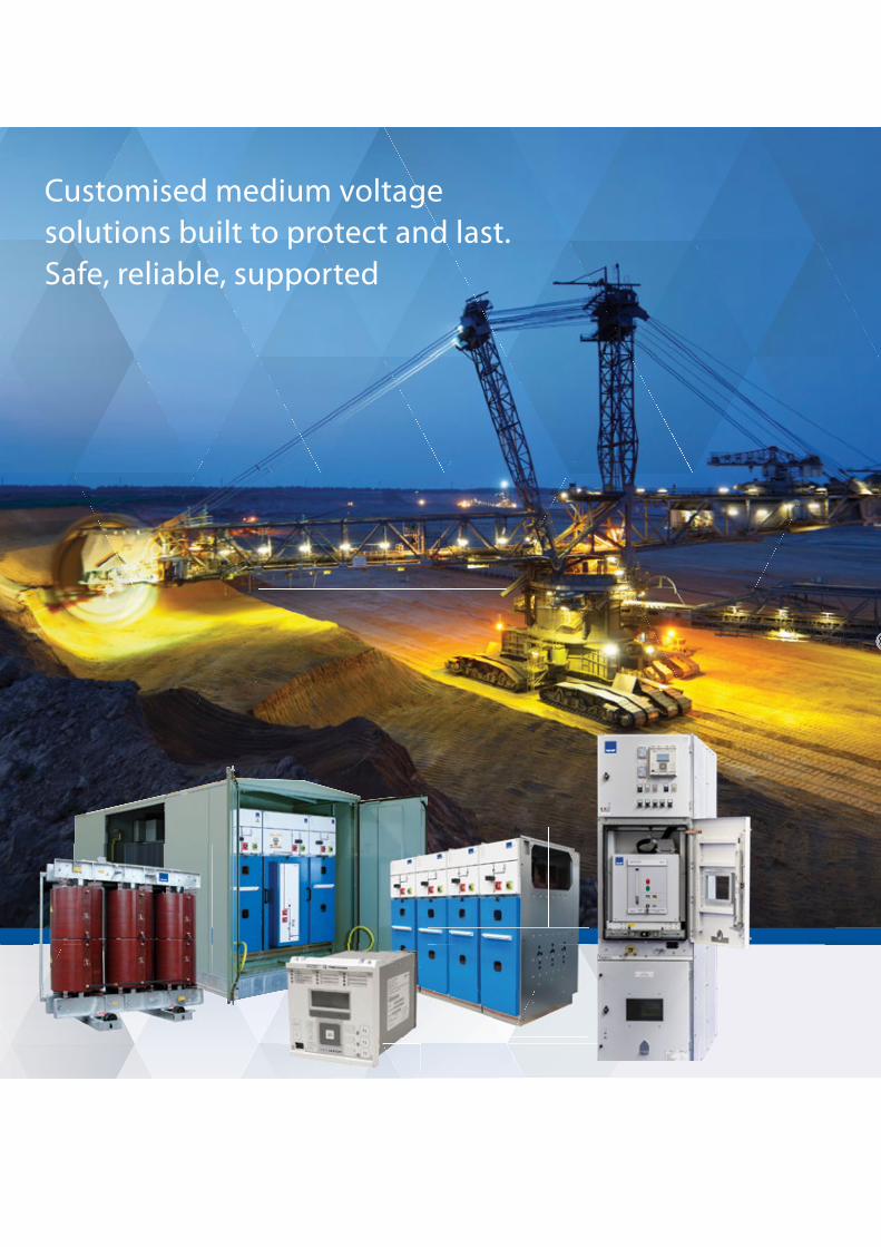
Customised medium voltage solutions built to protect and last. Safe, reliable, supported
nhp.com.au
Front Cover Industrial Electrix exact 36510 .indd 1 2/11/2016 2:47 PM
35
Customised medium voltage solutions built to protect and last. Safe, reliable, supported
nhp.com.au
Front Cover Industrial Electrix exact 36510 .indd 1 2/11/2016 2:47 PM
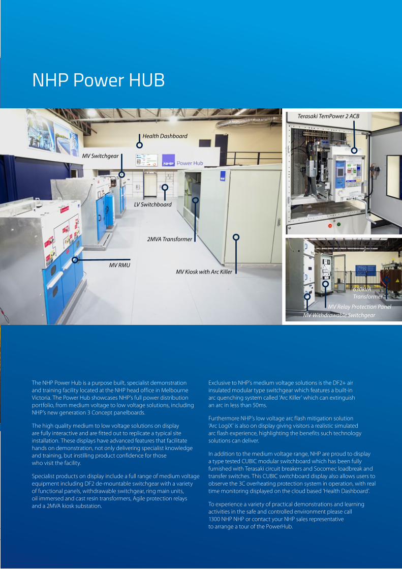
The NHP Power Hub is a purpose built, specialist demonstration and training facility located at the NHP head office in Melbourne Victoria. The Power Hub showcases NHP’s full power distribution portfolio, from medium voltage to low voltage solutions, including NHP’s new generation 3 Concept panelboards.
The high quality medium to low voltage solutions on display are fully interactive and are fitted out to replicate a typical site installation. These displays have advanced features that facilitate hands on demonstration, not only delivering specialist knowledge and training, but instilling product confidence for those who visit the facility.
Specialist products on display include a full range of medium voltage equipment including DF2 de-mountable switchgear with a variety of functional panels, withdrawable switchgear, ring main units, oil immersed and cast resin transformers, Agile protection relays and a 2MVA kiosk substation.
Exclusive to NHP’s medium voltage solutions is the DF2+ air insulated modular type switchgear which features a built-in arc quenching system called ‘Arc Killer’ which can extinguish an arc in less than 50ms.
Furthermore NHP’s low voltage arc flash mitigation solution ‘Arc LogiX’ is also on display giving visitors a realistic simulated arc flash experience, highlighting the benefits such technology solutions can deliver.
In addition to the medium voltage range, NHP are proud to display a type tested CUBIC modular switchboard which has been fully furnished with Terasaki circuit breakers and Socomec loadbreak and transfer switches. This CUBIC switchboard display also allows users to observe the 3C overheating protection system in operation, with real time monitoring displayed on the cloud based ‘Health Dashboard’.
To experience a variety of practical demonstrations and learning activities in the safe and controlled environment please call 1300 NHP NHP or contact your NHP sales representative to arrange a tour of the PowerHub.
MV Kiosk with Arc Killer
630kVA Transformer
Terasaki TemPower 2 ACB
MV Relay Protection PanelMV Withdrawable Switchgear
2MVA Transformer
LV Switchboard
MV Switchgear
Health Dashboard
MV RMU
NHP Power HUB

NHP Electrical Engineering Products A.B.N. 84 004 304 812
NHP97142 06/18
© Copyright NHP 2018
For more information, scan to download the NHP eCatalogues App o�ering exclusive video content, catalogues and literature!
For more information, scan to download the NHP eCatalogues App offering exclusive
video content, catalogues and literature
AUSTRALIAnhp.com.au
SALES 1300 NHP NHP
NEW ZEALANDnhp-nz.com
SALES 0800 NHP NHP