Embed Size (px)
Citation preview


QLMacro AssemblerincorporatingQL-Linker and
QL-Screen Editor
First published in 1985Sinclair Research Ltd25 Willis RoadCB1 2AQ England
ISBN 1 85016 047 3
and Sinclair QL are Registered Trade Marks of SinclairResearch Ltd. QL Microdrive and SuperBASIC are Trade Marks ofSinclair Research Ltd.
Copyright NoticeThis product is copyright material and may not be copied in whole orin part for any purpose whatsoever without the permission of thecopyright owner.
Macro Assembler and Linker Program and Documentation © GSTComputer Systems Ltd 1985Screen Editor Program and Documentation © Metacomco Ltd 1984Packaging and Design © Sinclair Research 1985Illustration © Jenny Tylden-Wright 1984.

Important Notes for New UsersThe instruction manual for QL Macro Assembler is in three parts,describing in detail how to use each of the three programs whichmake up the package:
§ Macro Assembler§ Linker§ Screen Editor
Each program's documentation is self-contained, but werecommend that you read the introductions to each section tofamiliarise yourself with their contents before you start.
Back-up copies
You are advised to make a back-up copy of each master cartridgeusing the clone program provided. Place the blank cartridge inMicrodrive 1 and the master cartridge in Microdrive 2. Then type:
Lrun mdv2_clone
and follow the instructions on the screen.

QL-Macro Assembler

Contents
1. Introduction 1 .1 Notation used in this manual
2. How to run the assembler 2.1 The command line
3. Assembler inputs and outputs 3.1 Control inputs 3.2 Source inputs 3.3 Screen output 3.4 Source listing 3.5 Symbol table listing 3.6 Object code output
4. Listing outputs 4.1 Source listing 4.2 Symbol table listing
Appendix A Bibliography
Appendix B Source languageB.1 Lexical analysisB.2 Source language line formatB.3 ExpressionsB.4 Addressing modesB.5 InstructionsB.6 Assembler directivesB.7 Macro facilitiesB.8 The macro library
Appendix C Error and warning messagesC.1 Error messagesC.2 Warning messagesC.3 Operating system error messages

1
1. IntroductionThis manual tells you how to use the QL Macro Assemblerproduced by GST Computer Systems Limited.
it tells you:
n how to load and run the assembler
n what inputs the assembler takes and what outputs it produces
n how the assembler language instructions should be coded
n what assembler directives are available, what they do, and how to code them.
It does not:
n include a detailed description of the instruction set of the Motorola MC68000 processor family (which includes the 68008 as used in the QL) for which you will need additional
documentation
n tell you how to talk to Qdos, the QL's operating system, for which you will have to consult the QL Technical Guide
n teach programming in general
n teach assembler programming or 68000 programming inparticular.
Appendix A contains a list of some other publications which youmay find helpful.

2
1.1 Notation used in this manualThis section describes the notation used throughout the manual todescribe syntax of assembler source, as well as other items.
= means that the expression on the right defines the meaning of the item on the left, and can be read as 'is'
< > angle brackets containing a lower-case name represent a named item which is itself made up from simpler items, such as <decimal number>
| a vertical bar indicates a choice and can be read as 'or is'
[ ] square brackets indicate an optional piece of syntax that may appear 0 or 1 times
{ } curly brackets indicate a repeated piece of syntax that may appear 0 or more times
... is used informally to denote an obvious range of choices, as in:
<digit> = 0|1|...|8|9
Other symbols stand for themselves.
Example
<binary number> = %<binary digit>{<binary digit>}
<binary digit> = 0|1
means that a binary number is a'%' sign followed by a binary digit,followed by any number of further binary digits, where a binary digitis the character '0' or the character '1 '. Some examples of binarynumbers are %0, %1010101100, %0000000000000.

3
Some of the_ special symbols used in the syntax notation alsooccur in the assembler source input and the common sense of thereader is relied on to distinguish these, as in for example:
<operator> = ...|<<|...
At some points in the description of the macro facilities thecharacters [, ], {, }must actually be coded as part of the assemblersource program. Where it is not obvious whether these charactersmust be coded (in which case they are 'literal') or whether they areused as defined above to describe syntax (in which case they are'metasymbols') their actual meaning is stated explicitly in each case.

4
2. How to run the assemblerYou can Load and run QL Macro Assembler in one of two ways:
Interactive mode
In this mode the assembler will identify itself and prompt you for a command line. Upon completion of an assembly the assembler will prompt you for a further command line, so that you may perform several assemblies without reloading the program.
When you have done all the assemblies you want you can terminate the assembler by replying to its prompt with a blank command line.
You may run the macro assembler in interactive mode by any of the following commands where DEV is the device from which it is to be loaded (which may be any storage medium).
– To run in parallel with the SuperBASIC interpreter:
EXEC DEV_MAC or: EX DEV_MAC
– To wait for completion of the assembler:
EXEC_W DEV_MAC or: EW DEV_MAC
Non-interactive mode
In this mode the assembler receives its command line directly from the SuperBASIC interpreter and does not interact with you. On completion of the assembly the assembler will exit and will need to be reloaded if you wish to perform another assembly.
You may run the macro assembler in non-interactive mode by one of the following commands:

5
– To run in parallel with the SuperBASIC interpreter:
EX DEV_MAC; "<command line>"
– To wait for completion of the assembler:
EW DEV_MAC; "<command line>"
where <command line> is described below. The quotes round the command line are required by the SuperBASIC interpreter.
Notes
The EX and EW commands are only available in the QL Toolkit andare not part of standard SuperBASIC.
The EX and EW commands allow you to pass data files to theprogram by specifying them after the program name. If any files arespecified in this way they will be ignored by the assembler. See theQL Toolkit documentation for information on the full use of the EXand EW commands.
If you wish to change the screen window used by the macroassembler you may do so by running the program WINDOW_MGRand answering the questions it asks.
2.1 The command lineSee section 3 of this manual for a description of all the various filesand devices that the assembler can use.
The format of the command line is:
<source>[<listing>[<binary>]] {<option>}

6
where:
<option> = –NOLIST| –ERRORS [<listing>]| –LIST [<listing>]|
–NOBIN| –BIN [<binary>]|
–NOSYM| –SYM|
–NOLINK
(the options may be in upper or lower case and case is notsignificant)
<source> = <file name> file name of assembler source<listing> = <file name> file name for listing output<binary> = <file name> file name for binary output
The options have the following meanings:
–NOLIST do not generate any listing output
–ERRORS generate a listing of error messages and erroneous lines only; if the option is followed by a <file name> then this is the name of the <listing> output and the positional <listing> parameter, if coded, is not used; the –ERRORS option also sets the –NOSYM option
–LIST generate a full listing; if the option is followed by a <file name> then this is the name of the <listing> output and the positional <listing> parameter, if coded, is not used
–NOBIN do not generate any binary output
–BIN generate binary output; if the option is followed by a <file name> then this is the name of the <binary> output file and the positional <binary> parameter, if coded, is not used
–NOSYM do not generate a symbol table listing; this is the default if –ERRORS is coded

7
–SYM generate a symbol table listing; this is the default if –LIST is coded or if no listing options are coded; if both –SYM and –NOLIST are both coded then the –SYM does nothing
–NOLINK normally the QL Macro Assembler generates output in S–ROFF format which must then be linked by the QL Linker; the –NOLINK option instructs the assembler to generate an output program file which can be run directly
Where conflicting options are given the last one coded takes effect.For example if:
–LIST MDV1_FRED –NOLIST –ERRORS
is coded then an errors-only listing will be sent to MDV1_FREDand if:
–SYM –ERRORS
is coded then no symbol table output will be generated.
The minimum command line just consists of the name of the inputsource file. In this case a full listing with symbol table is generated(i.e. the default is –LIST–SYM) to the file whose name isconstructed from the <source> <file name> as described below.Also by default a binary output file is generated (i.e. the default is –BIN) to the file whose name is constructed from the <source><file name> as described below.
The <source> <file name> is examined; if its last four characters(after converting to upper case) are not _ASM then _ASM isappended to the given name to make the name of the actual sourcefile used.
The name of the <listing> file may be given positionally as thesecond parameter, or may be specified explicitly after an –ERRORSor –LIST option, or may be allowed to default. If no <listing><file name> is given in an –ERRORS or –LIST option and no –NOLIST option has been coded then the assembler constructs the<listing> <file name> by taking the <source> <file name>, asadjusted, and replacing the _ASM with _LIST.

8
The name of the <binary> file may be given positionally as the thirdparameter, or may be specified explicitly after a –BIN option, ormay be allowed to default. If no<binary> <file name> is given in a –BIN option and no –NOBIN option has been coded then theassembler constructs the <binary> <file name> by taking the<source> <file name>, as adjusted, and replacing the _ASM with_REL in the normal case or _BIN if –NOLINK has been coded.
Examples
MDV1_FRED
assemble MDV1_FRED_ASM, put a full listing with symbol tablelisting in MDV1_FRED_LIST, and put the binary inMDV1_FRED_REL
MDV1_FRED SER1 –NOBIN
assemble MDV1_FRED_ASM, print the listing as it is produced,and don't generate any binary
MDV1_FRED –ERRORS –BIN MDV2_FRED_REL
Assemble MDV1_FRED_ASM, send an error listing only with nosymbol table to MDV1_FRED_LIST, and put the binary inMDV2_FRED_REL (note that coding MDV2_FRED would not haveachieved this)
MDV1_FRED SER1 MDV2_FRED_REL –ERRORS –SYM
assemble MDV1_FRED_ASM, print an error listing plus symboltable directly and put the binary in MDV2_FRED_REL

9
3 Assembler inputs and outputsThis chapter describes all the input and output files and devices thatthe assembler can use.
3.1 Control inputs
Control information for the assembler is supplied by the user typinga command line on the keyboard. The command line is described insection 2 above and specifies where all the other input and outputfiles and devices are.
3.2 Source inputs
The assembler assembles one main source file. This may direct theassembler, using INCLUDE directives, to read other source files.
When assembling large and complicated programs it is normal toput no real code at all in the main source file which will just containINCLUDE directives naming the other source files. For example:
TITLE A large complicated assembly** Start with the Qdos parameter file,* then the parameter file for my program* INCLUDE MDV1_QDOS_IN INCLUDE MDV1_MYPARMS_IN** Now the main code to to be assembled:* this is rather* large so it is split into two separate* files
INCLUDE MDV2_PROG1_ININCLUDE MDV2_PROG2_IN
END

10
The file name of the main source file must end in _.ASM, or theassembler will not be able to find it.
It is recommended that file names of INCLUDEd files end in _IN,but this is not essential, and you can call them anything you like.
3.3 Screen output
The assembler writes a certain amount of information to the screento let the user know what is happening. This includes a 'start'message, a 'finished' message and the request to type thecommand line.
A summary of the number of errors and warnings generated iswritten to the screen together with a summary of the amount ofmemory used. This memory size excludes the memory occupied bythe code of the assembler itself (about 30k) and the assembler'sinitial data space (about 4k).
You can get a good idea of how complicated your assemblies areand whether you are likely to run out of memory by watching thememory use figure. On an unexpanded QL it is possible toassemble a source file which occupies virtually the whole of aMicrodrive cartridge as long as no other major task is running at thesame time.
If you do several assemblies in one go (without reloading theassembler) then the assembler will return any memory it hasobtained to the operating system at the end of each assembly.
The assembler also tells you when it is starting to read the sourceinput for the first time and when it is starting to read the sourceinput for the second time. The second pass can be expected totake a lot longer than the first pass if listings and/or binary outputare wanted. The symbol table listing is produced after the summarymessages are displayed, so if you are assembling a large programit will be an appreciable time after the summary messages aredisplayed before the assembler is finished completely.

11
3.4 Source listingAn optional source listing will be generated, showing the sourceinput and the code that has been generated.
The listings provided are controlled both by options on thecommand line (see section 2 above) and by directives coded in thesource program (see appendix B below).
If the –NOLIST option is given then there will be no listing outputfrom the assembler. Under all other circumstances a file or devicewill be used to produce a listing.
If the file name for the listing output is generated automatically bythe assembler it will end in _LIST. It is recommended that listingfiles, when stored on Microdrive, always have file names ending in_LIST, but this is not a requirement and you can call them anythingyou like.
Listings can be printed directly as they are generated (using SER1or SER2 or some add-on printer device) or can be sent to thescreen (using CON_) as an alternative to sending them toMicrodrive.
3.5 Symbol table listingA symbol table listing will be produced if both the –LIST and –SYMoptions are in effect.
The symbol table listing will be added to the end of the sourcelisting, starting on a new page.

12
3.6 Object code output3.6.1 Relocatable (S–ROFF) outputNormally the assembler will produce a relocatable binary output filein S–ROFF format (the standard Sinclair relocatable output fileformat). This output file may be linked using the Sinclair QL Linkerwith other files in the same format generated by the QL MacroAssembler and/or files in the same format generated by compilersfor other languages.
Each assembly generates a single module (see the QL Linkersection for more information about the details of the S–ROFFformat and how to link together S–ROFF object files).
If you code a MODULE directive somewhere in your sourceprogram then that directive will specify the name of the module. Ifyou do not code a MODULE directive then the assembler willconstruct one from the name of the primary source file by strippingthe _ASM off the end of the file and stripping the first component(assumed to be a device name such as MDV2_) off the beginning.
For example, if the primary input file is called:
FLP2_SYSTEMX_PART3_ASM
then the default module name will be:
SYSTEMX_PART3
Other information is included as part of the module directive in theS–ROFF file, including the name of the assembler and the time anddate of the assembly:
3.6.2 Directly executable outputAlternatively the QL Macro Assembler may generate a directlyexecutable output file which may be run as a program using theEXEC or EXEC_W command without any need for linking. To makeuse of this option you must code –NOLINK In the command line(see section 2 above) and you must not use most of the assemblerdirectives which relate to linker functions. See the description ofeach directive for full details.

13
4. Listing outputsThere are two listings produced by the assembler: the source listingand the symbol table listing:
Each line of listing produced can be up to 132 characters long(excluding the terminating newline); in particular each title line is132 characters long. Some printers cannot be made to print 132characters to a line so the PAGEWID directive (q.v.) is provided tospecify the actual width of the printer. Any line longer thanPAGEWID characters will be allowed to overflow onto the followingline, and these overflows will be taken into account whendetermining whether a page is full.
The listing output is paginated with the total page length defined bythe user in a PAGELEN directive (q.v.) or allowed to default. Toobtain essentially unpaginated output you may set PAGELEN to avery large number, in which case only one title will be printed at thebeginning of the listing, and form feeds will be included at the startand end of the listing and between the source and symbol tablelistings only.
The format of each printed page is:
<heading> <blank> <title> <blank> <blank> <listing> <form feed>
where:
<heading> is a line containing the name and version of the assembler, the name of the source file being assembled, the page number, and the time and date

14
<blank> is a blank line (i.e. a line feed character)
<title> is the <title string> given on the relevant TITLE directive; if no relevant TITLE directive has been coded then this line is <blank>
<listing> consists of (PAGELEN–14) lines of listing of whatever format is appropriate (source listing or symbol table listing)
<form feed> is the ASCII form feed character and appears immediately after the line feed which terminates the last line (if any) of <listing>
4.1 Source listingNote that if the –ERRORS option has been requested then not allsource lines are listed; only lines containing errors are listed,together with the error messages.
Each line of listed source code has the following format:
Columns Field contents Format
1 – 4 line number 4-digit decimal
5 macro flag blank or +
6 – 7 section number 2-digit hex
8 (blank)
9 – 16 location counter 8-digit hex
17 (blank)
18 – 29 generated code up to 12 digits hex

15
30 (blank)
31 – 132 source line as coded, truncated to fit
Source line numbers start at 1 for the first line in the (main) sourcefile and are incremented by 1 for each source line processedregardless of the file or macro from which it came and regardless ofwhether the line is listed or not.
The macro flag is blank if the line being listed came directly from aninput file or contains the character ‘+’ if the line was generated by amacro.
The section number is an internal number used to indicate whichSECTION is being assembled; this number ties up with the sectionnumber given in the list of sections in the symbol table listing. It isleft blank when absolute addresses (such as those generatedunder the influence of an OFFSET or ORG directive) are beingdisplayed.
For instructions and data definition directives the location counterfield contains the address which would be assigned to a labeldefined on that source line; note that this is not necessarily thesame as the value of the location counter after the previous line hasbeen processed. For other directives containing expressions whosevalue is likely to be of interest to the user (e.g. OFFSET, EQU) thevalue of the expression is printed in the location counter field or thecode field, as appropriate. If there is nothing useful that can beprinted in this field then it is left blank.
The generated code field contains up to 6 bytes of code generatedby an instruction to a data definition directive (DC or DCB). If aninstruction generates more than 6 bytes of code then a secondlisting line is used to display the rest of it; this second listing line isblank apart from the generated code field (and possibly some errorflags). Code in excess of 6 bytes generated by DC or DCBdirectives is not printed; if you want to see it you should codeseveral separate DC or DCB directives.
The length of the listing line is in all cases limited to 132 characters,any excess (probably comment) being truncated.

16
The source line printed on the listing is normally the fully expandedversion of the line after values have been substituted for all macroparameters, functions and variables. However in the case of anerror occurring during substitution, a partially expanded form of theline may be listed with an error message giving the reason for theproblem.
Error and warning messages are interspersed with the sourcelisting; each message follows the listing of the line to which it refers.If a line has errors or warnings it is followed by a line containing avertical bar character ( | ) below the part of the source line givingoffence. The format of the messages is:
* * * * * * ERROR xx – line nnnn – mmmm – <message>
* * * * WARNING xx –line nnnn – mmmm – <message>
where xx is the error number, nnnn is the line number of the linecontaining the error, mmmm is the line number of the linecontaining the previous error (0 if none) to allow the user to chainthrough all the error messages to make sure none have beenmissed, and <message> is a helpful message saying what is wrong.There are separate chains for error and warning messages.
The line giving rise to an error or warning is always listed,regardless of the state of any LIST, NOLIST, EXPAND orNOEXPAND directives. Thus the listing generated by –ERRORS ismore or less the same as the listing generated by –LIST if NOLISTdirectives are in force throughout.
If there is no END directive a special warning message is printedrelating to this at the end of the assembly; the line number in thiswarning message is one greater than the number of the last line inthe input file.
At the end of the assembly a summary of the number of errors andwarnings generated is output both to the listing, if there is one, andto the screen

17
4.2 Symbol table listingThe symbol table listing consists of three separate listings: a list ofall the sections used in the assembly, the main cross-referencelisting of normal user symbols, and a cross-reference listing ofmacros.
4.2.1 The section reportThe section report precedes the main symbol table listing. It hasone line for each section name or common block name used in theassembly, each line having the following form:
Columns Field contents Format
1 – 8 symbol up to 8 characters
9 (blank)
10 – 13 symbol type SECT or COMM
14 (blank)
15 – 16 section number 2-digit hex
17 (blank)
18 – 25 size 8-digit hex
The size field contains the size of the section or common block.
As all sections are the same if the –NOLINK option has beenselected and no common blocks can exist at all, this report doesnot appear when –NOLINK has been selected.

18
4.2.2 User symbol cross-reference.This report lists all user defined operand-type symbols and givesthe line number for each occasion on which the symbol was used.
Columns Field contents Format
1 – 8 symbol up to 8 characters
9 (blank)
10 – 13 symbol type see below
14 (blank)
15 – 16 section number see below
17 (blank)
18 – 25 value 8-digit hex
26 (blank)
27 -PAGEWID cross-references see below
The symbol type field contains one of:
MULT the symbol is multiply defined; the assembler will use the first definition and print error messages for subsequent ones
XREF the symbol is defined by an XREF directive
XDEF the symbol is used in an XDEF directive
REG the symbol is a register list defined by a REG directive
blank anything else

19
The section number field only contains useful information if thesymbol type field is blank (or XDEF) in which case it is one of:
blank symbol depends on no section or common block base addresses
number symbol depends (with a count of +1) on one common block or section base address, and this is the relevant section number
XX symbol depends on more than one section or common block base address or depends on one but with a count other than +1
In the –NOLINK case absolute symbols will have this field blankand relocatable symbols will have the number 00 printed.
If the symbol is undefined then the section number and value fieldswill contain the word 'undefined'.
The rest of the line (up to the defined PAGEWID) will be filled withcross-reference information. If there is more than enough of this tofill the line it will continue on subsequent lines starting at column 27.
Each cross-reference consists of six characters as follows:
1 – 4 line number 4-digit decimal5 definition flag blank or '*'6 (blank)
and gives the number of a line on which the symbol was used. If theuse of the symbol is a defining occurrence then the line number isfollowed by an asterisk.
Cross-references for a particular symbol are printed in ascendingorder of line numbers.
4.2.3 Macro cross-referenceThis is a cross-reference listing of all macros involved in theassembly. It is in the same format as the symbol cross-referencelisting but the symbol type, section number and value fields are allblank.

20
A. BibliographyQL Technical GuideThis manual describes the facilities of Qdos that are available to theassembler programmer and tells you how to call them.
You will need this book to write machine code programs for the QL.It does not attempt to teach 68000 programming.
Available from Sinclair Research Limited, Stanhope Road,Camberley, for £14.95 mail-order.
M68000 16/32 Bit Microprocessor Programmer's ReferenceManualThis is the Motorola handbook for the 68000 (reference numberM68000UM). It contains definitions of the 68000 instruction set (asdoes the King and Knight book) and in addition contains more low-level information, such as details of the binary code for eachinstruction and some hardware information.
Available from GST Computer Systems Limited, 91 High Street,Longstanton, Cambridge, for £8.95 mail-order.
Programming the MC68000by Tim King and Brian Knight, Addison-Wesley
This is an excellent book which teaches assembler programming onthe 68000 and also contains a complete description of the 68000'sinstruction set. It is suitable for the first-time assembler programmeralthough you should do some programming in another language,such as SuperBASIC, before using assembler. This book is alsovery valuable to the experienced assembler programmer who hasnot used a 68000 before as it points out many of the commonerrors and pitfalls which usually cause trouble for the newcomer tothe 68000.
Available from GST Computer Systems Limited, 91 High Street,Longstanton, Cambridge, for £8.95 mail-order.

21
B. Source languageThis appendix defines the source language accepted by theassembler. It does not specify the details of the Motorola 68000instruction set and a manual for the 68000 itself must be consultedfor this information.
B.1 Lexical analysisThis section defines the way in which characters are combined tomake tokens. The notation used is described in section 1.
Generally a line of assembler source is divided into the traditionalfour fields of label, operation, operand and comment, the fieldsbeing separated by spaces. There are some exceptions to thiswhich are concerned with the macro facilities of the assembler.
Thus spaces are significant in this language, apart from justterminating symbols.
As a special case a line containing an asterisk (*) in column oneconsists entirely of comment and is treated as a blank line.
A semicolon (;) at any position in a line (as long as it is not inside a<string> or an <arbitrary string>) introduces a comment; thesemicolon and the rest of the line are ignored.
Any syntactic token is terminated either by the first character whichcannot form part of that token or by end of line.
<syntactic token> = <white space> | <symbol> | <number> | <string> | <newline> | <<|>>| ! | # | & | ( | ) | * | + | , | - | / | :
(where <newline> is a line feed character)

22
<white space> = <space>{<space>}
(where <space> is the ASCII space character)
<symbol> = <start symbol> { <rest symbol> }
<start symbol> = <letter> |.
<rest symbol> = <letter> | <digit> | $ | . | __
<letter> = a | b | ... | y | z | A | B | ... | Y | Z
note that (outside strings) whether a letter is upper or lower case is not significant
note that a symbol can be any length but only the first eight characters are significant
<number> = <binary number> | <octal number> | <decimal number> | <hex number>
<binary number> = % <binary digit> {<binary digit>}
<octal number> = @<octal digit>{<octal digit>}
<decimal number> = <digit>{<digit>}
<hex number> = $<hex digit>{<hex digit>}
<binary digit> = 0 | 1
<octal digit> = 0 | 1 | ... | 6 | 7
23
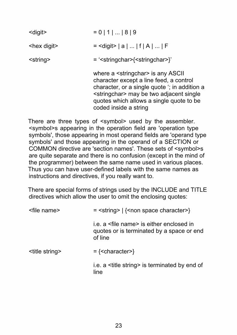
<digit> = 0 | 1 | ... | 8 | 9
<hex digit> = <digit> | a | ... | f | A | ... | F
<string> = ‘<stringchar>{<stringchar>}’
where a <stringchar> is any ASCII character except a line feed, a control character, or a single quote ‘; in addition a <stringchar> may be two adjacent single quotes which allows a single quote to be coded inside a string
There are three types of <symbol> used by the assembler.<symbol>s appearing in the operation field are 'operation typesymbols', those appearing in most operand fields are 'operand typesymbols' and those appearing in the operand of a SECTION orCOMMON directive are 'section names'. These sets of <symbol>sare quite separate and there is no confusion (except in the mind ofthe programmer) between the same name used in various places.Thus you can have user-defined labels with the same names asinstructions and directives, if you really want to.
There are special forms of strings used by the INCLUDE and TITLEdirectives which allow the user to omit the enclosing quotes:
<file name> = <string> | {<non space character>}
i.e. a <file name> is either enclosed in quotes or is terminated by a space or end of line
<title string> = {<character>}
i.e. a <title string> is terminated by end of line

24
There is a special form of string used in some macro andconditional assembly directives:
<arbitrary string> = any sequence of characters not including space or comma ',' or backslash ' \' or semicolon ';' |
{any sequence of characters)
where the { } are literal (i.e. they must be coded and are not part of the syntax description).
There is a special set of operators used in the conditional assemblydirectives:
<compop> = < | <= | >= | > | ~= | <>
where ~= and <> are alternate ways of coding "not equals"
Note that in macro calls and some conditional assembly directivesthe backslash character '\' is used to indicate that the statement iscontinued on the following line of input.
Note that the open square bracket character '[' is used to indicatevariable substitution and may not appear in any other context (e.g.it may not appear with any other meaning in a <string> or <arbitrarystring> or comment).
B.2 Source language line formatThis section defines the various forms which a source line can take.
A source line consists of between 0 and 132 characters (excludingthe line feed character).
Basically a source line consists of the following four fields:

25
label (optional, but depends on operation)operation (optional)operand (depends on operation)comment (optional)
A source line can be blank (including consisting entirely of commentas defined above) in which case it is ignored for all purposes otherthan those connected with output listings; a blank line is assigned aline number, is printed on the listing, and its position may affect theoperation of the title directive.
Some macro and conditional assembly directives may be codedover more than one source line; any such line which is to becontinued on the next line ends with a backslash '\' (optionallyfollowed by comment). Full details are given when the directivesconcerned are described.
B.2.1 The label fieldA line contains a label field if it starts with one of the followingsequences of tokens:
<symbol><white space><symbol>:<white space><symbol>:
i.e. a label starting in column 1 may be followed by <white space>or a colon, but a label starting further along the line must beterminated by a colon.
Such a sequence at the start of a line is referred to elsewhere inthis appendix as a <label>.
If a line contains a label and contains nothing after the label thenthe label is defined with the current value of the current locationcounter; otherwise the meaning of the label depends on theoperation field.

26
B.2.2 The operation fieldThe operation field follows the (optional) label field and its syntax is:
[<white space>]<symbol>
The symbol is one of:
– an assembler directive – a 68000 instruction – a macro name
B.2.3 The operand field
The syntax of the operand field depends on the operation.<white space> terminates the operand except in the case of amacro call or a conditional assembly directive.
The syntax of each format of the operand field is described belowwhen the operation is defined.
B.2.4 The comment fieldWhen enough of the rest of the line has been processed to satisfythe operation (for the majority of operations this is up to the first<white space> beyond the start of the operand field) anything lefton the line is deemed to be comment and ignored.
It is, however, good practice to use the semicolon (;) to introducecomments on macro calls and conditional assembly directives asthis will avoid confusing both the assembler and the human reader.
B.3 ExpressionsExpressions are constructed from:
– unary operators: + , - – binary operators: + , - , / , * , >> , << , & , ! –parentheses: (, ) –operands: <symbol>, <number>, * , <string>

27
<string>s used in expressions must be four characters long orshorter. The value of a <string> consists of the ASCII values of thecharacters right-justified in the normal 32-bit value. Thus, forexample, the two expressions
'a'*256+'b' and 'ab'
have the same value. (Note, that the DC directive can use longerstrings with different evaluation rules)
The character * used as an expression operand has the same valueas a <label> defined on the line in which the * is used would have.
The syntax of an expression is then:
<expr> = <symbol> | <number> | * | <string> | (<expr>) | + <expr> | - <expr> | <expr> <binaryop> <expr>
<binaryop> = + | - | / | * | << | >>| & | !
The operators have the following meanings:
unary + the value of the operand is unchangedunary - the value of the operand is negated
Note that all operands are regarded as 32 bit values; these valuesare obtained by extending the original operand on the left withzeroes (all operands are originally positive except that symbols canbe defined to have negative values, in which case they will alreadybe 32 bit negative numbers). Likewise all intermediate and finalresults from expressions are calculated as 32 bit values, and aretruncated as necessary according to context just before being used.
binary + addition
binary - subtraction
* multiplication

28
/ division: the result is truncated towards zero
<< shift left: the left operand is shifted to the left by the number of bits specified by the right operand, which should be an absolute value between 0 and 32 inclusive otherwise the result is undefined; vacated bits at the right hand end are filled with zeroes
>> shift right; as for shift left but the operand is shifted right
& bitwise logical AND
! bitwise logical OR
The order of evaluation of expressions is as follows:
1 parenthesised expressions are evaluated first (in the natural way)2 operators are evaluated according to priority; the order of priorityis (highest first):
unary + , – << , >> &, I * , / binary + , –
3 operators of the same precedence at the same nesting level ofparentheses are evaluated from left to right.
B.3.1 Values A value (of a symbol or of an <expr> or of a partially evaluatedsub-expression etc.) consists of a numeric term (4 bytes) and a listof relocation bases to be added or subtracted.
See B.3.2. below for details of which symbols have which values.

29
Values can be classified into various types by the followingproperties:
Addressing mode This is an indication of the requested addressing mode required and is one of: normal no specific request; interpret it as absolute or relocatable depending on the relocation factor
XREF.S the value consists of a single symbol which was declared in an XREF.S directive
XREF.L the value is either a more complicated construction involving XREF.S symbols or contains a reference to a symbol declared in an XREF.L directive
Relocation factor This is the number of times the value is expected to be relocated finally by both assembler and linker with respect to the start address of the whole program. Each XREF (but not XREF.S or XREF.L) and label defined within a SECTION added into the value contributes +1 to this count and each such symbol subtracted from the value contributes -1 to this count.
If the relocation factor is 0 the value is regarded by the assembler as absolute.
If the relocation factor is 1 the value is regarded by the assembler as simple relocatable.
If the relocation factor is anything else the value is regarded by the assembler as complex relocatable.
Number of relocation bases This is the number of different XREF[<xlen>] symbols and base addresses of SECTIONs involved in the value (after any cancelling out has been done).

30
COMMON dependency This is an indication of whether any symbol forming the value was the name of a COMMON section.
B.3.2 Values of various operand typesThis section lists the various operands and describes the type ofvalue they possess.
Numbers and strings Numbers and strings have a value whose numeric term is the value of the number or string.
Addressing mode: normal Relocation factor: 0 Relocation bases: none COMMON dependency: no
The current location counter The value of the current location counter (*) is equal to the value a label coded on the same line would have, and the value is of identical form.
Labels Symbols which are defined as labels in range of OFFSET, ORG or COMMON directives have values whose numeric term is the numeric value of the symbol.
Addressing mode: normal Relocation factor: 0 Relocation bases: none COMMON dependency: no
Symbols which are defined as labels in range of SECTION directives have values whose numeric term is the offset of the label from the start of the section (within the module).
Addressing mode: normal Relocation factor: +1 Relocation bases: 1: start address of section COMMON dependency: no

31
Symbols defined in XREF directives Symbols which are defined in (any type of) XREF directives have a numeric term of zero and a single relocation base which is the external reference to the symbol.
For symbols defined by XREF:
Addressing mode: normal Relocation factor: + 1 Relocation bases: 1: the symbol COMMON dependency: no
For symbols defined by XREF.S or XREF.L:
Addressing mode: XREF.S or XREF.L Relocation factor: 0 (but irrelevant to the user) Relocation bases: 1: the symbol COMMON dependency: no
Section names Section names as used in SECTION directives are not operand type symbols, cannot be referred to anywhere other than in SECTION directives, and have no value
Common block names Common block names have values whose numeric term is zero.
Addressing mode: XREF.L Relocation factor: 0 (but irrelevant to the user) Relocation bases: 1: start address of the common block COMMON dependency: yes
Symbols defined by EQU The value of a symbol defined by an EQU directive is the value of the <expr> coded on the EQU directive. For a definition of how values of expressions are derived, see below.
Undefined symbolsSymbols which are undefined at the point of reference (usuallybecause they are forward references but sometimes because theyare errors) are treated as labels defined in range of a SECTIONdirective.

32
B.3.3 Rules for operator processingThis section describes how the various operators combine values tomake new values. See above for details of the actual arithmeticoperations performed.
Unary + This operator is ignored.
Unary - The sub-expression:
–<subexpr>
is treated in identical fashion to:
(0–<subexpr>)
(taking due account of operator priorities), see the description of binary subtraction below.
Binary addition Addition of two normal operands will result in a normal value.
The relocation factor of the result will be the sum of the relocation factors of the operands.
The relocation bases involved in both operands are added together. If a particular relocation base occurs with a positive sign in one operand and a negative sign in the other it is cancelled out.
Addition of two operands at least one of which is of type XREF.S or XREF.L will result in a value of type XREF.L. The relocation factor and relocation bases are kept track of in the same way as for the normal case.
Binary subtraction Subtraction of two normal operands will result in a normal value.
The relocation factor of the result will be the difference of the relocation factors of the operands.

33
The relocation bases involved in both operands are subtracted in the appropriate direction. If a particular relocation base occurs with the same sign in both operands it is cancelled out.
Subtraction of two operands at least one of which is of type XREF.S or XREF.L will result in a value of type XREF.L. The relocation factor and relocation bases are kept track of in the same way as for the normal case.
All other operators These operators are only valid if both operands are of the following form:
Addressing mode: normal Relocation factor: 0 Relocation bases: none COMMON dependency: no
and will produce error messages otherwise.
B.4 Addressing modesThis section defines all addressing modes that can be coded asinstruction operands. For a definition of what these addressingmodes actually do consult a manual for the Motorola 68000.
B.4.1 Addressing mode syntaxA number of symbols are reserved and have special meaning whenused in operands: these are names of various registers.
D0 to D7 data registers also the symbols D0.W, D0.L etc.
A0 to A7 address registers also the symbols A0.W, A0.L etc.
SP synonym for A7 also the symbols SP.W, SP.,L
34
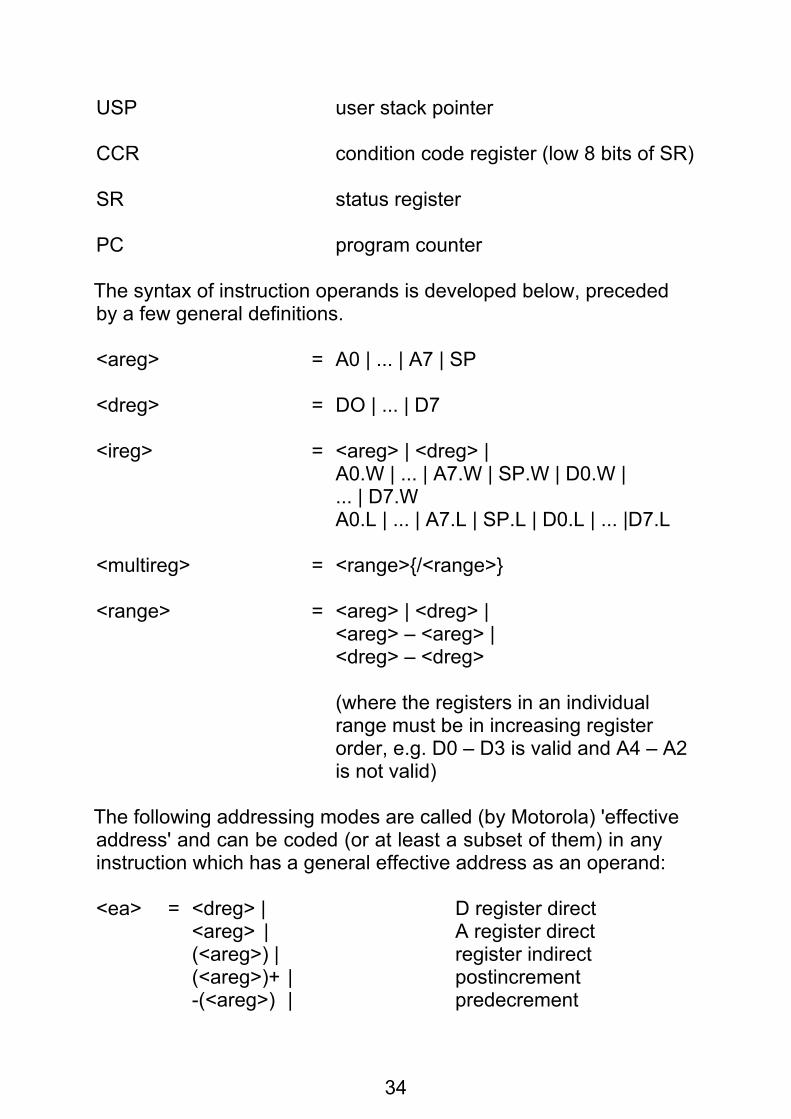
USP user stack pointer
CCR condition code register (low 8 bits of SR)
SR status register
PC program counter
The syntax of instruction operands is developed below, precededby a few general definitions.
<areg> = A0 | ... | A7 | SP
<dreg> = DO | ... | D7
<ireg> = <areg> | <dreg> | A0.W | ... | A7.W | SP.W | D0.W | ... | D7.W A0.L | ... | A7.L | SP.L | D0.L | ... |D7.L
<multireg> = <range>{/<range>}
<range> = <areg> | <dreg> | <areg> – <areg> | <dreg> – <dreg>
(where the registers in an individual range must be in increasing register order, e.g. D0 – D3 is valid and A4 – A2 is not valid)
The following addressing modes are called (by Motorola) 'effectiveaddress' and can be coded (or at least a subset of them) in anyinstruction which has a general effective address as an operand:
<ea> = <dreg> | D register direct <areg> | A register direct (<areg>) | register indirect (<areg>)+ | postincrement -(<areg>) | predecrement
35
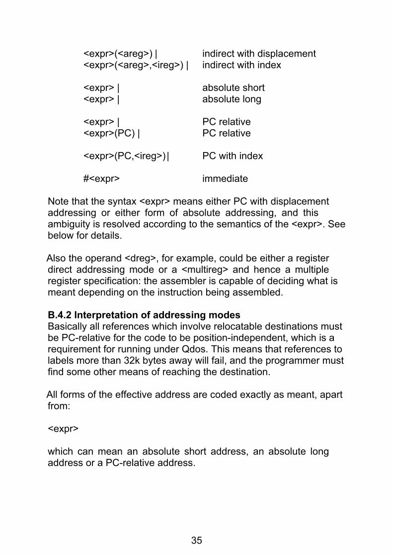
<expr>(<areg>) | indirect with displacement <expr>(<areg>,<ireg>) | indirect with index
<expr> | absolute short <expr> | absolute long
<expr> | PC relative <expr>(PC) | PC relative
<expr>(PC,<ireg>) | PC with index
#<expr> immediate
Note that the syntax <expr> means either PC with displacementaddressing or either form of absolute addressing, and thisambiguity is resolved according to the semantics of the <expr>. Seebelow for details.
Also the operand <dreg>, for example, could be either a registerdirect addressing mode or a <multireg> and hence a multipleregister specification: the assembler is capable of deciding what ismeant depending on the instruction being assembled.
B.4.2 Interpretation of addressing modesBasically all references which involve relocatable destinations mustbe PC-relative for the code to be position-independent, which is arequirement for running under Qdos. This means that references tolabels more than 32k bytes away will fail, and the programmer mustfind some other means of reaching the destination.
All forms of the effective address are coded exactly as meant, apartfrom:
<expr>
which can mean an absolute short address, an absolute longaddress or a PC-relative address.

36
The addressing mode generated depends on whether the referringinstruction is in absolute code (in the range of an ORG) orrelocatable code (in the range of a SECTION). This tablesummarises the generated addressing modes:
From To Generatesabs abs absolute short or long as appropriate reloc absolute long forward absolute long XREF absolute long XREF.S absolute short XREF.L absolute long
reloc abs absolute short or long as appropriate reloc PC-relative forward PC-relative XREF PC-relative XREF.S absolute short XREF.L absolute long
If the value of the expression is complex relocatable the assemblerwill produce an error message.
Forward references within absolute code will always be generatedas absolute long addresses. You can code an explicit (PC) to makesuch references PC-relative, but there is no way to force them to beabsolute short.
Forward references which are undefined at the time of meeting thesymbol are assumed to be simple relocatable. If the programmerwishes to reference an absolute address this can only be done bycoding a number, or by coding a symbol which has previously beenequated to a number. For example:
MOVE.B #$80,SCREEN ...... ...........SCREEN EQU $18063

37
(within a SECTION) is not legal and will generate an error,whereas:
JMP FRED
... ....
FRED
(within a SECTION) is legal and will generate a PC-relativeaddressing mode.
An immediate operand #<expr> where the <expr> is not absolutewill probably generate wrong code, as the assembler does notknow where the code will be loaded and executed and is unable toadd the necessary relocation base(s). Therefore, the assembler willgenerate warning messages if a relocatable <expr> is used as animmediate operand.
B.4.3 Branch instructionsThe branch instructions (Bcc, BSR) can use either an 8-bit PC-relative displacement or a 16-bit displacement; the assembler willcorrectly choose the most efficient option for a backwards referencebut needs some help with forward references. The default option isto generate a long (16-bit) displacement.
These branch instructions can have an explicit extent coded of .S(short) meaning that an 8 bit displacement is to be used or .L (long)meaning that a 16 bit displacement is to be used, for example:
BNE.S FRED FRED is not very far away
B.5 InstructionsThis section lists all the 68000 instruction mnemonics, describeshow the various modifiers are coded, and defines the operandsyntax of each instruction. Note, however, that for precise details ofthe actual addressing modes etc. legal for each instruction, amanual for the Motorola 68000 should not be consulted.

38
An instruction may optionally have a <label>. Before any code foran instruction is generated the current location counter is advancedto an even address, if not already even. It is this adjusted addressthat is assigned to the <symbol> in the <label>.
B.5.1 Instruction mnemonic formatThe operation field of a source line containing a machine instructionis simply a <symbol>. However there is some flexibility allowed inthe coding of mnemonics as there are some generic mnemonicsthat relate to a group of instructions, the actual instruction wantedbeing chosen by the assembler depending on the operands coded.
Instructions which may operate on operands of different lengthsmust have the length of the operand coded as part of the<symbol>: this takes the form of '.B', '.W' or '.L' as the last twocharacters of the <symbol> depending on whether the operandlength is byte, word or long. If a length is required and no length iscoded the assembler will assume .W and will print a warningmessage.
Instructions which may only take a single operand length mayoptionally have the length coded as above.
A dot '.' as the last character of an instruction (or directive or macro)name in the operation field of a source line is ignored (e.g. theexchange instruction may be coded as EXG, EXG. or EXG.L). Thisfeature is sometimes useful when designing macros.
The branch instructions may optionally have .S or .L coded as thelast two characters of the <symbol> to indicate the displacementsize as described at B.4.3 above.
Examples
MOVE.L an instruction with an operand length coded
BEQ.S an instruction with an extent coded
JSR an instruction with no extra bits
39
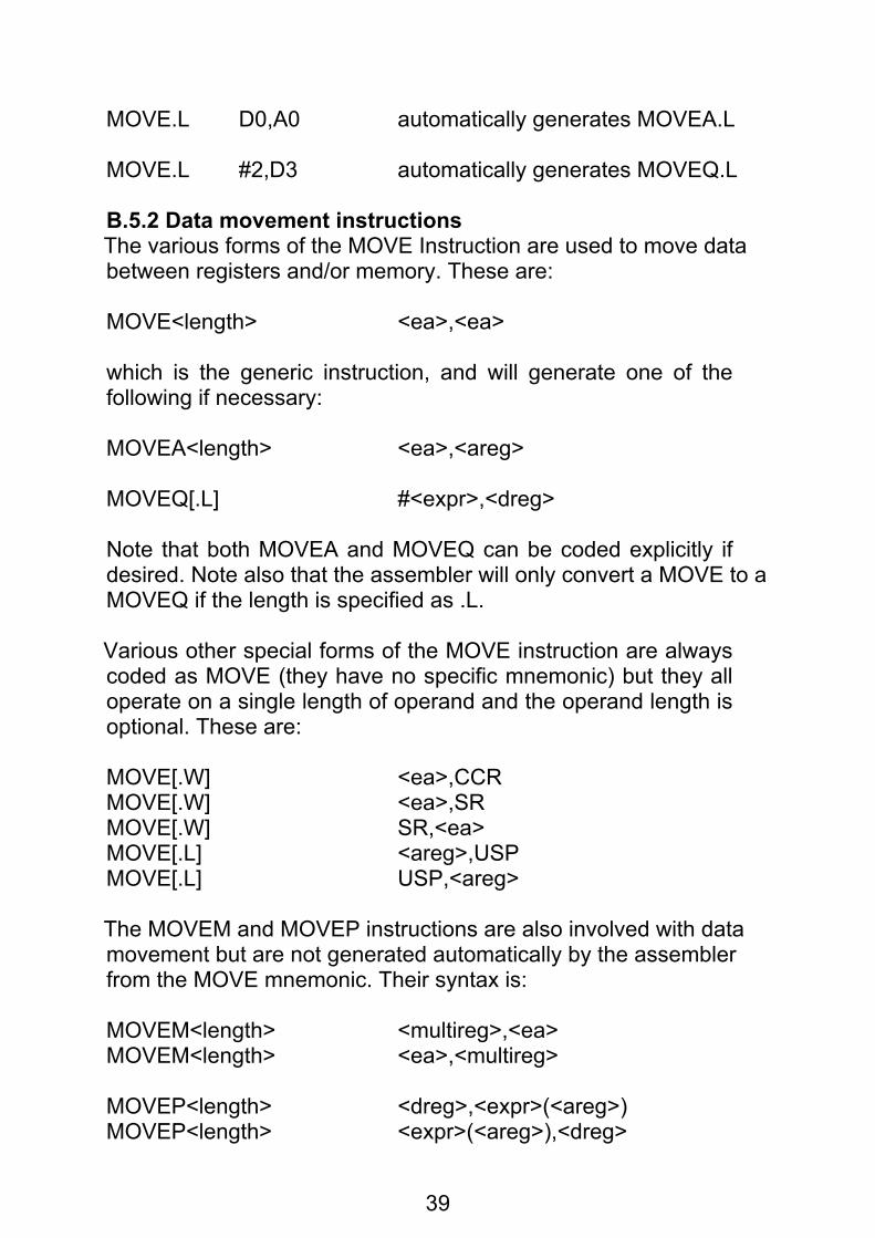
MOVE.L D0,A0 automatically generates MOVEA.L
MOVE.L #2,D3 automatically generates MOVEQ.L
B.5.2 Data movement instructionsThe various forms of the MOVE Instruction are used to move databetween registers and/or memory. These are:
MOVE<length> <ea>,<ea>
which is the generic instruction, and will generate one of thefollowing if necessary:
MOVEA<length> <ea>,<areg>
MOVEQ[.L] #<expr>,<dreg>
Note that both MOVEA and MOVEQ can be coded explicitly ifdesired. Note also that the assembler will only convert a MOVE to aMOVEQ if the length is specified as .L.
Various other special forms of the MOVE instruction are alwayscoded as MOVE (they have no specific mnemonic) but they alloperate on a single length of operand and the operand length isoptional. These are:
MOVE[.W] <ea>,CCRMOVE[.W] <ea>,SRMOVE[.W] SR,<ea>MOVE[.L] <areg>,USPMOVE[.L] USP,<areg>
The MOVEM and MOVEP instructions are also involved with datamovement but are not generated automatically by the assemblerfrom the MOVE mnemonic. Their syntax is:
MOVEM<length> <multireg>,<ea>MOVEM<length> <ea>,<multireg>
MOVEP<length> <dreg>,<expr>(<areg>)MOVEP<length> <expr>(<areg>),<dreg>
40
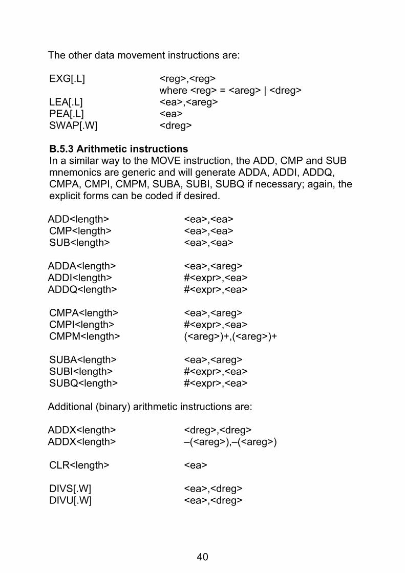
The other data movement instructions are:
EXG[.L] <reg>,<reg> where <reg> = <areg> | <dreg>LEA[.L] <ea>,<areg>PEA[.L] <ea>SWAP[.W] <dreg>
B.5.3 Arithmetic instructionsIn a similar way to the MOVE instruction, the ADD, CMP and SUBmnemonics are generic and will generate ADDA, ADDI, ADDQ,CMPA, CMPI, CMPM, SUBA, SUBI, SUBQ if necessary; again, theexplicit forms can be coded if desired.
ADD<length> <ea>,<ea>CMP<length> <ea>,<ea>SUB<length> <ea>,<ea>
ADDA<length> <ea>,<areg>ADDI<length> #<expr>,<ea>ADDQ<length> #<expr>,<ea>
CMPA<length> <ea>,<areg>CMPI<length> #<expr>,<ea>CMPM<length> (<areg>)+,(<areg>)+
SUBA<length> <ea>,<areg>SUBI<length> #<expr>,<ea>SUBQ<length> #<expr>,<ea>
Additional (binary) arithmetic instructions are:
ADDX<length> <dreg>,<dreg>ADDX<length> –(<areg>),–(<areg>)
CLR<length> <ea>
DIVS[.W] <ea>,<dreg>DIVU[.W] <ea>,<dreg>

41
EXT<length> <dreg>
MULS[.W] <ea>,<dreg>MULU[.W] <ea>,<dreg>
NEG<length> <ea>NEGX<length> <ea>
SUBX<length> <dreg>,<dreg>SUBX<length> –(<areg>), (<areg>)
TST<length> <ea>
The binary coded decimal instructions are written as follows:
ABCD[.B] <dreg>,<dreg>ABCD[.B] –(<areg>),–(<areg>)
NBCD[.B] <ea>
SBCD[.B] <dreg>,<dreg>SBCD[.B] –(<areg>),–(<areg>)
B.5.4 Logical operationsAND, EOR, OR are generic mnemonics that will generate ANDI,EORI, ORI as necessary:
AND<length> <ea>,<dreg>AND<length> <dreg>,<ea>AND<length> #<expr>,<ea>ANDI<length> #<expr>,<ea>
EOR<length> <dreg>,<ea>EOR<length> #<expr>,<ea>EORI<length> #<expr>,<ea>
NOT<length> <ea>
OR<length> <ea>,<dreg>OR<length> <dreg>,<ea>OR<length> #<expr>,<ea>ORI<length> #<expr>,<ea>

42
There are special forms of the ANDI, EORI and ORI instructionswhich operate on the status register.
AND.B #<expr>,SRAND.W #<expr>,SRAND [.B] #<expr>,CCR
ANDI.B #<expr>,SRANDI.W #<expr>,SRANDI[B] #<expr>,CCR
EOR.B #<expr>,SREOR.W #<expr>,SREOR[.B] #<expr>,CCR
EORI.B #<expr>,SREORI.W #<expr>,SREORI[.B] #<expr>,CCR
OR.B #<expr>,SROR.W #<expr>,SROR[.B] #<expr>,CCR
ORI.B #<expr>,SRORI.W #<expr>,SRORI[.B] #<expr>,CCR
B.5.5 Shift operationsASL<length> <dreg>,<dreg>ASL<length> #<expr>,<dreg>ASL[.W] <ea>
ASR<length> <dreg>,<dreg>ASR<length> #<expr>,<dreg>ASR[.W] <ea>
LSL<length> <dreg>,<dreg>LSL<length> #<expr>,<dreg>LSL[.W] <ea>

43
LSR<length> <dreg>,<dreg>LSR<length> #<expr>,<dreg>LSR[.W] <ea>
ROL<length> <dreg>,<dreg>ROL<length> #<expr>,<dreg>ROL[.W] <ea>
ROR<length> <dreg>,<dreg>ROR<length> #<expr>,<dreg>ROR[.W] <ea>
ROXL<length> <dreg>,<dreg>ROXL<length> #<expr>,<dreg>ROXL[.W] <ea>
ROXR<length> <dreg>,<dreg>ROXR<length> #<expr>,<dreg>ROXR[.W] <ea>
B.5.6 Bit operationsThe length specification is optional on these instructions as thelength must be long if the <ea> is a <dreg> and must be byte if the<ea> is anything else.
BCHG[<length>] <dreg>,<ea>BCHG[<length>] #<expr>,<ea>
BCLR[<length>] <dreg>,<ea>BCLR[<length>] #<expr>,<ea>
BSET[<length>] <dreg>,<ea>BSET[<length>] #<expr>,<ea>
BTST[<length>] <dreg>,<ea>BTST[<length>] #<expr>,<ea>

44
B.5.7 Branch instructionsThe branch instructions may optionally have an extent (.S or .L)coded as described at B.4.3 above.
B<cc>[<extent>] <expr>
where:
<cc> = CC | CS | EQ | GE | GT | HI | LE | LS | LT | MI | NE | PL | VC | VS | HS | LO
<extent> = .S | .L
The unconditional branch instruction is:
BRA[<extent>] <expr>and is in fact a version of the conditional branch instruction thatmeans "branch regardless of the condition codes".
The branch to subroutine instruction is:
BSR[<extent>] <expr>
B.5.8 Trap instructionsGrouped here are those instructions whose main purpose is togenerate traps, either conditionally or unconditionally.
CHK[.W] <ea>,<dreg>TRAP # <expr>TRAPV
B.5.9 The DBcc instructionThis instruction is a looping primitive; it tests the condition codes asdoes the Bcc instruction but also allows the conditions "always true"and "always false" to be tested.
DB<dbcc>[.W] <dreg>,<expr>

45
where:
<dbcc> = <cc> | T | F | RA
RA is a synonym for F, meaning branch regardless of the conditioncodes; thus the instruction DBRA loops without testing conditionsother than the value of the loop counter.
B.5.10 Jump instructionsThe jump instructions are an unconditional jump and a subroutinecall:
JMP <ea>JSR <ea>
See section B.4.2 for a definition of how the assembler interprets<expr> as an <ea>, as that paragraph is particularly relevant tothese two instructions.
B.5.11 Stack frame management
LINK <areg>, # <expr>UNLK <areg>
B.5.12 Odds and ends
NOPRESETRTERTRRTSTAS[.B] <ea>STOP #<expr>
The Scc instruction has the same set of conditions as DBcc but notthe RA synonym:
S<scc>[.B] <ea>
where:
<scc> = <cc> | T | F

46
B.6 Assembler directivesAssembler directives are instructions to the assembler and, with theexception of DC and DCB, do not directly generate any code. Thedirectives provided are summarised below.
The following directives must not have labels:
INCLUDE read another source file
SECTION relocatable program sectionORG absolute program sectionCOMMON COMMON sectionRORG adjust current locationOFFSET define offset symbols
DATA specify data spaceEND end of program
XREF refer to external symbolsXDEF define symbols to be externalMODULE define module name for the linkerCOMMENT include comment in linker listing
The following directives require labels:
EQU assign value to symbolREG define register list
The following directives may optionally have labels:
DC define constantsDS reserve storageDCB define constant block
The following are listing control directives and must not have labels:
PAGE start new listing pagePAGEWID define width of pagePAGELEN define length of pageLIST switch listing on
47
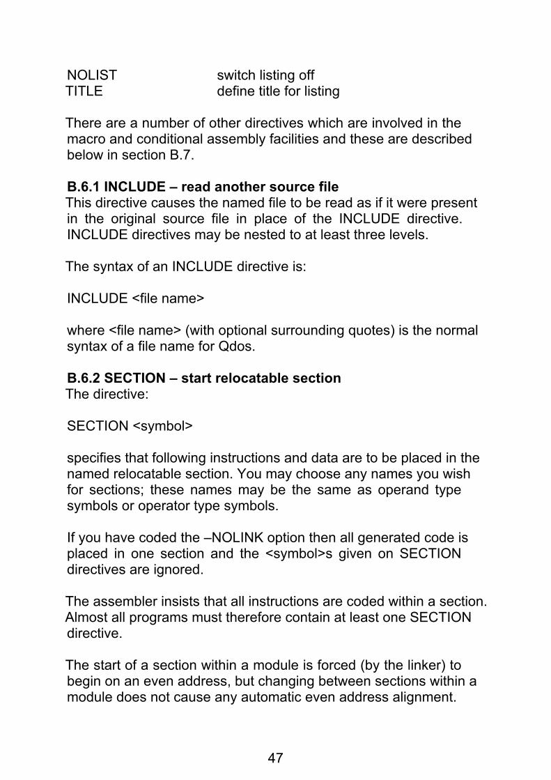
NOLIST switch listing offTITLE define title for listing
There are a number of other directives which are involved in themacro and conditional assembly facilities and these are describedbelow in section B.7.
B.6.1 INCLUDE – read another source fileThis directive causes the named file to be read as if it were presentin the original source file in place of the INCLUDE directive.INCLUDE directives may be nested to at least three levels.
The syntax of an INCLUDE directive is:
INCLUDE <file name>
where <file name> (with optional surrounding quotes) is the normalsyntax of a file name for Qdos.
B.6.2 SECTION – start relocatable sectionThe directive:
SECTION <symbol>
specifies that following instructions and data are to be placed in thenamed relocatable section. You may choose any names you wishfor sections; these names may be the same as operand typesymbols or operator type symbols.
If you have coded the –NOLINK option then all generated code isplaced in one section and the <symbol>s given on SECTIONdirectives are ignored.
The assembler insists that all instructions are coded within a section.Almost all programs must therefore contain at least one SECTIONdirective.
The start of a section within a module is forced (by the linker) tobegin on an even address, but changing between sections within amodule does not cause any automatic even address alignment.

48
For example:
SECTION ONEDC.B 1 this starts on an even address
SECTION TWO ...... ... (anything)
SECTION ONEDC.B 2 this byte is at an odd address
The section names are neither operand type symbols nor operatortype symbols and therefore you cannot refer to a section namefrom anywhere other than a SECTION directive.
It is however possible to have an operand type symbol with thesame name as a section name, and it is possible to declare thisname to be an external symbol, for example:
SECTION FRED
FRED: XDEF FRED
In this example the symbol FRED refers to the first address in thesubsection of FRED which resides in the current module, and thissymbol is available to other modules which may refer to it usingXREF.
B.6.3 ORG – start absolute sectionThe directive:
ORG <expr>
instructs the assembler to generate code at the absolute addressspecified by <expr>, which must be absolute and contain noexternal or forward references.
The ORG directive is not permitted if the –NOLINK option has beencoded.

49
The use of the ORG directive renders the resulting programposition-dependent so that it will not normally be possible to run itas a Qdos program.
B.6.4 COMMON – start COMMON sectionThe directive:
COMMON <symbol>
introduces a common section in the same way as the SECTIONdirective introduces an ordinary section.
The COMMON directive is not permitted if the –NOLINK option hasbeen coded.
This directive exists to allow declaration of and access to Fortran-style common blocks. This is not considered to be a generallyuseful feature and is included solely to enable assembler access todata structures used by Fortran (or other high level languageswhich make use of the Fortran COMMON scheme).
The COMMON directive creates the <symbol> of section type (asdoes the SECTION directive); it also creates an operand typesymbol of the same name as if it had been declared with anXREF.L directive. The value of this symbol is an offset from aglobal origin of common blocks.
In the two cases which are not re-entrant (default and COMMONEND - see the QL Linker manual) the global origin of commonblocks is the start of the program, and in the re-entrant case(COMMON DUMMY) it is the start of the store area allocated to thecommon blocks (which is not known until run-time).
There is no way to tell the assembler which type of commonallocation will be performed by the linker, but the way the assemblerhandles common allows most of the code to be the same for bothcases.
The symbols declared as labels within a COMMON section haveabsolute values as if they were declared within range of anOFFSET 0 directive. They are intended to be used as offsets to anaddress register which holds the address of the base of thecommon block.

50
You must ensure that an address register is allocated throughout tohold the address of the base of all common blocks, and theinitialisation of this register depends on whether code which is notre-entrant is being generated in which case something like:
LEA COMMBASE(PC),A5
will do, or whether re-entrant code is being generated in which casea call to the operating system to allocated memory space will returnthe address of the base of that space.
From here on the same code can be used in both cases: to obtainthe base address of common block FRED above in A4:
MOVE.L A5,A4 base of all common blocksADD.L #FRED,A4 base of FRED
and you can then move data around in the common block in thesame way in both cases, e.g.:
MOVE.L VAR1(A4),VAR2(A4)
Note that this code knows that VAR1 and VAR2 are within 32kbytes of the start of FRED but makes no assumptions about wherethe linker will put FRED in relation to the start of all common blocks.If you know that the whole program (in the non-re-entrant case) orthe total size of all common blocks (in the re-entrant case) is lessthan 32k you may use:
ADD.W #FRED,A4
instead, and the linker will complain if there is any overflow.
Note that the use of the symbols VAR1 etc. in any other way islikely to be unhelpful, for example code like:
MOVE.L VAR1,VAR2
will do silly things like trying to copy parts of the operating systemROM around.

51
Within range of a COMMON directive DS and RORG directives mayalways be coded. If the code generated is to be non-re-entrant thenDC and DCB directives may also be coded. In no circumstancesmay instructions be coded.
If re-entrant code is required (linker option COMMON DUMMY) andDC or DCB directives are coded within range of a COMMONdirective then the linker will generate error messages.
B.6.5 RORG – adjust relocatable originThe directive
RORG <expr>
resets the current location counter to <expr> bytes from the start ofthe current section or common section. RORG directives must onlybe coded following a SECTION or COMMON (with no interveningOFFSET or ORG).
If the <expr> in a RORG directive has a value higher than theaddress of any code generated in the section then the length of thesection is increased to this value which will be used by the linker inperforming address allocation.
The <expr> may be absolute or relocatable; in the latter case itmust be simple relocatable with respect to the current section. Itmust contain no forward or external references and must not benegative.
The <expr> must not contain any symbols which are COMMONsection names.
B.6.6 OFFSET – define offset symbolsThe OFFSET directive provides a means for symbols to be definedas offsets from a given point: this is particularly useful for definingfield names for data structures.
The <expr> given in an OFFSET directive must be absolute andmust not contain forward references or external references. Thevalue of the <expr> is the initial value of a dummy location counterwhich can then be used to define labels on following DS directives.

52
The syntax of the OFFSET directive is:
OFFSET <expr>
Between an OFFSET directive and a following OFFSET orSECTION (or END) directive the following are not allowed:
DC, DCB, instructions.
B.6.7 END – end of programThe END directive defines the end of the source input; if there isanything else in the file on subsequent lines then this will beignored by the assembler.
The syntax of the end statement is:
END
B.6.8 XREF – refer to external symbolThe directive:
XREF[<xlen>] <symbol>{,<symbol>}
declares the listed <symbol>s to be external. Code within thecurrent module may make references to these symbols and thereferences will be resolved by the linker.
The XREF directive for a symbol must occur before any otherreference to the symbol otherwise the assembler will report an error.The XREF directive is not permitted if the –NOLINK option hasbeen coded.
When a <symbol> declared in an XREF directive forms (possiblypart of) an <expr> which is coded where a general effectiveaddress (<ea>) is required the user must give the assembler somehelp in choosing the addressing mode required. This is done via the<xlen> field.

53
<xlen> may be blank, in which case the assembler will usuallygenerate PC-relative addressing modes when the <symbol>s arereferred to, or '.S' in which case the assembler will generateabsolute short addressing modes when the <symbol>s are referredto, or '.L' in which case the assembler will generate absolute longaddressing modes when the symbols are referred to.
Note that (for example) a relocatable symbol may be referred to byXREF.L, in which case absolute long address references to it maybe made. In most circumstances the linker will end up with the rightanswer for this sort of thing as long as you didn't want the programto be position independent.
The rules for the addressing mode chosen when an <expr>contains several symbols of different types are discussed at B.4.2above.
A symbol may be declared in more than one XREF directive (so that,in particular, XREFs can be used in macros with no worries aboutduplicate declarations). (If the same symbol is defined more thanonce in the same XREF then some harmless error messages willresult.)
B.6.9 XDEF – declare external symbolThe directive:
XDEF <symbol>{,<symbol>}
declares the <symbol>s to be external. These symbols should bedefined in the current module and are made available to othermodules by this declaration.
There are no positioning requirements on the XDEF directive, whichmay occur either before or after any other uses of the <symbol>s.The XDEF directive is not permitted if the –NOLINK option hasbeen coded. A symbol may appear in more than one XDEFdirective.

54
Due to restrictions imposed by the relocatable binary format and thelinker only some types of <symbol> can be coded in an XDEFdirective. The following types of <symbol> can be coded in anXDEF directive:
some absolute symbols, being:
labels following an ORG directive
symbols defined by an EQU directive which involve no (residual) external references and no (residual) SECTION or COMMON relocation bases
some symbols whose value is an offset from the start of aSECTION present in the current module, being:
labels following a SECTION directive
symbols defined by an EQU directive which involve no (residual) external references and only one (residual) SECTION relocation base with a relocation factor of 1.
The following types of symbol cannot be coded in an XDEFdirective due to the relocatable binary and linker restrictions:
symbols defined by an EQU directive which involve one or more residual external references and/or more than one residual SECTION relocation base and/or any SECTION relocation base with a relocation factor other than 1.
B.6.10 MODULE – declare module nameThe directive:
MODULE <title string>
is optional and specifies the contents of the source directive in theoutput relocatable binary file. Normally it is not necessary to code aMODULE directive and a default will be constructed by theassembler as described at 2.7.1 above.
The MODULE directive is ignored if the –NOLINK option has beencoded.

55
B.6.11 COMMENT – include comment in binaryThe directive:
COMMENT <title string>
places the string in the relocatable binary output file as a commentdirective. This has no effect on anything except that it is included inthe listing generated by the QL Linker.
The COMMENT directive is ignored if the –NOLINK option hasbeen coded.
B.6.12 EQU – assign value to symbolSyntax:
<label> EQU <expr>
The <expr> is evaluated and the value is assigned to the <symbol>given in the <label>.
The <expr> may not include references to any symbol which hasnot yet been defined.
The <expr> may include references to external symbols (defined byearlier XREF directives).
The value of the defined symbol is calculated as explained in B.3.1.
B.6.13 REG – define register listSyntax:
<label> REG <multireg>
The <symbol> given in the <label> is defined to refer to the registerlist given in <multireg> and may be used in MOVEM instructionsonly.
The purpose of this directive is to allow a symbol to be definedwhich represents a register list pushed at the start of a subroutineso that the same list of registers can be popped at the end of thesubroutine without the risks involved in writing the list out twice.

56
B.6.14 DC – define constantsThis directive defines constants in memory. Memory is reservedand the values of the constants given are stored in this memory.This facility is intended to allow constants and tables to be created.
Syntax:
[<label>] DC<length> <constant> {,<constant>}
where:
<constant> = <expr> | <string>
This directive may be coded within the range of a SECTION orORG directive. It may also be coded within the range of aCOMMON directive but this should only be done if the code is to benon-re-entrant.
If a <constant> consists of a single string and no other operators oroperands then it is left justified in as many bytes, words or longwords (depending on whether <length> is .B, .W or .L) asnecessary, with the last word or long word padded with zero bytesas necessary. In this case the <string> can be of any (non-zero)length; there is no restriction as there is with <string>s that formpart of <expr>s.
This leads to the rather strange feature that:DC.L 'a'
causes the character to be left-justified whereas
DC.L 'a'+0
is an <expr> and so causes the character to be right-justified. (Notethat other 68000 assemblers have even stranger features in thisarea.)

57
in,the case of DC.W and DC.L the current location counter isadvanced to a word boundary if necessary; and the optional<label> is defined with this adjusted value. Thus the codefragments:
FRED DC.W ....
and
FRED DC.W ...
do not necessarily have the same effect as the second could resultin FRED having an odd value depending on earlier use of DC.B,DS.B or DCB.B.
Expressions given as operands of DC directives may contain anylegal combination of external references.
Data to be generated may have any value type. However any datawith a relocation factor other than zero will cause a warningmessage to be produced as the result is probably a program whichis not position independent.
No more than six bytes of code generated by a DC are printed onthe listing; if all generated bytes are required. then the constantsmust be coded on more separate DC directives.
B.6.15 DS – reserve storageThis directive reserves memory locations. The memory contents areundefined. The directive is used to define offsets in conjunction withthe OFFSET directive and to leave 'holes' in data generated by DCand DCB; it is also of use in ensuring that the current locationcounter has an even value.
Syntax:
[<label>] DS<length> <expr>

58
If the length is .W or .L the current location counter (which can be adummy location counter initiated by OFFSET) is advanced to aword boundary if necessary. The (optional) <label> is assigned thevalue of the adjusted location counter.
The <expr> must be absolute and contain no forward or externalreferences.
DS.B reserves <expr> bytes, DS.W reserves <expr> words andDS.L reserves <expr> long words.
<expr> may have the value zero in which case DS.W and DS.Lensure that the location counter is on an even boundary, and theoptional <label> is defined.
B.6.16 DCB – define constant blockThe directive:
[<label>] DCB<length> <expr>,<expr>
causes the assembler to generate a block of bytes, words or longsdepending on whether <length> is .B, .W or .L.
This directive may be coded within the range of a COMMONdirective but this should only be done if the code is to be non-re-entrant.
If the length is .W or .L the current location counter is advanced to aword boundary if necessary. The (optional) <label> is assigned thevalue of the adjusted location counter.
The first <expr> must be absolute and contain no forward orexternal references and is the number of storage units (bytes,words or longs) to be initialised, and the second <expr> is the valueto be stored in each of these storage units.
The second <expr> may contain any legal combination of externalreferences.

59
Data to be generated may have any value type. However any datawith a relocation factor other than zero will cause a warningmessage to be produced as the result is probably a program whichis not position independent.
B.6.17 PAGE – start new listing pageThe directive
PAGE
causes the next line of the listing to appear at the top of the nextpage. The PAGE directive itself is not listed.
B.6.18 PAGEWID – define width of pageThe directive
PAGEWID <expr>
defines the width of the printed output to be <expr> characters. The<expr> must be absolute and contain no forward or externalreferences and must be between 72 and 132 inclusive. If noPAGEWID directive is present the default is 132 characters.
B.6.19 PAGELEN – define length of pageThe directive
PAGELEN <expr>
defines the length of each listing page to be <expr> lines. The<expr> must be absolute and must contain no forward or externalreferences. The value given is the physical length of the paper;rather fewer lines of assembler source are actually listed on eachpage.
B.6.20 LIST – switch listing onThe directive
LIST
restarts listing that was suppressed by a previous NOLIST directive.The LIST directive itself is not listed.

60
B.6.21 NOLIST– switch listing offThe directive
NOLIST
suppresses listing until a LIST directive is encountered. TheNOLIST directive itself is not listed.
B.6.22 TITLE – define title for listingThe directive
TITLE <title string>
causes the <title string> to be printed at the top of each subsequentpage of listing. If a title is wanted on the first page of the listing thenthe TITLE directive should appear before any source line whichwould get listed. The TITLE directive itself is not listed.
B.6.23 DATA – define size of data spaceThe directive
DATA <expr>
defines the size of the data space that will be allocated to theprogram when it is executed by Qdos. The <expr> gives thenumber of bytes to be reserved.
The expression must be absolute and contain no forward orexternal references.
If several DATA directives are coded the last one takes effect.
If no DATA directives are coded then 4096 bytes of data space willbe allocated to the program.

61
B.7 Macro facilitiesA macro is a set of assembler source statements (both instructionsand directives) which are given a name.
This set of statements may be included in your program at any pointby coding the name of the macro in the operation field of a sourceline as if it were a user-defined instruction or directive.
Thus a macro can be used as a shorthand way of writing a set ofstatements which has to be repeated several times in a program.
A set of text substitution and conditional assembly facilities is alsoprovided so that a macro need not generate exactly the samesequence of code each time it is used but can generate differentcode depending on parameters passed to it.
As all these facilities are interdependent it is not possible to arrangethis section of the manual so as to avoid forward referencesentirely: you may find it necessary to read right through section B.7quickly so as to gain a general understanding and then read itagain to study the details.
B.7.1 Text substitutionThe input to the assembly process may come from the input files orfrom a macro which is being expanded. In either of these cases(but not while a macro definition is being processed or on acomment line introduced by an asterisk '*' in column 1) anyoccurrence of:
[<variable>]
(where the [ ] are literal) will be replaced by the string valuecurrently associated with the <variable>. There are two (syntactic)types of <variable>, being <symbols>s or calls to functions:
<variable> = <symbol> | <function>
<function> =<symbol>[(<parm>{,<parm>})]

62
<parm> = <variable> | <expr> | <ea>
(where the [ ] and { } are metasymbols). A <parm> may beinterpreted as a <variable> or an <expr> or an <ea> depending onthe type of data required for that parameter by the particularfunction.
Substitutions can be nested. For example, suppose the currentvalue of the variable N is the string '3' (not including the quotes) andthe current value of the variable VAR3 is the string ‘A value’ (notincluding the quotes) then the assembler source:
DC. B '[VAR[N]]'
will be expanded to:
DC.B 'A value'
For a list of functions provided in the assembler see B.7.4.
Note that the character '[' will always attempt to cause a substitutionand so this is effectively a reserved character in that anyattempt to code it as part of a string or comment will always causeeither a substitution or an error message.
For a discussion of the scope of variables and macro parameterssee B.7.3.
B.7.2 Macro definitionsA macro definition begins with the directive:
<label> MACRO [<symbol>{,<symbol>}]
the commas are optional and macro parameters can alternatively orin addition be separated by <white space>; in addition the commaor <white space> can be followed by a backslash character ' \' inwhich case the rest of the line is ignored and the next parameter istaken from the next input line

63
(where the [ ]{ }are metasymbols) and ends with the directive:
ENDM
Macro definitions may not be nested.
The <label> is defined to be the name of the macro. It is defined asan operator type symbol (and must not therefore clash with anydirective, instruction or other macro name).
The list of <symbol>s gives names to the parameters to the macro.The macro parameters may then be accessed by substituting forthe parameters as variables, e.g.:
FRED MACRO P1,P2 ... DS.W [P2] ... ENDM
Alternatively the functions .NPARMS and .PARM may be used toaccess the parameters and in this case no prior knowledge of thenumber of parameters to be coded is needed. Example:
FRED MACRO P1,P2 ... DS.W [.PARM(2)] ... ENDM
has the same effect as the previous example.
When a macro definition is encountered in the assembler's input it isscanned without any string substitution until an ENDM directive isfound. The ENDM must therefore be coded directly and must not begenerated by substitution! This also applies to the MACLABdirective (see B.7.7).

64
B.7.3 Defining variablesVariables may be declared as local to a macro either by theirappearance as macro parameters on the MACRO directive or bytheir appearance in LOCAL directives. This does not assign anyvalues to the variables.
Variables are given values by SETSTR or SETNUM directives. Inaddition variables which are macro parameters are given valueswhen the macro is called.
The values of variables are used when the variable name appearsin square brackets[ ].
The LOCAL directiveThe directive
LOCAL <symbol>{,<symbol>}
(where the { } are metasymbols) declares the <symbol>s to belocal variables within the macro currently being expanded. None ofthe <symbol>s may appear as a parameter name for the currentmacro or in another LOCAL directive in the same macro.
For a full discussion of the scope of variables see below.
The SETSTR directive
The directive
<label> SETSTR <arbitrary string>defines the <label> to be a variable and assigns it the<arbitrary string> as its value.
See below for a discussion of the scope of variables. Variables canbe set (using SETSTR and/or SETNUM, see below) as often as youlike during an assembly.

65
When setting a variable to a string value which does not contain anyspecial characters which might confuse the assembler (space,comma, semicolon) it is not necessary to code the curly brackets{ } round the <arbitrary string>, for example:
FRED SETSTR The.value.of.bertBERT SETSTR 197.999WOMBAT SETSTR [FRED]=[BERT]
When one of these special characters is required the curly bracketsmust be coded, for example:
STRING SETSTR {This has spaces in it}STRING2 SETSTR {'and so does this'}STRING3 SETSTR {don't take; semicolon as comment}NULL SETSTR {} how to set a null stringDANGER SETSTR {[A]) don't know if A contains spaces
The SETNUM directiveThe directive
<label> SETNUM <expr>
evaluates the <expr>, converts the final numeric result to a string,and assigns this string to the variable <label> in the same way asfor SETSTR.
The use of SETNUM is often for counting;
COUNT SETNUM [COUNT]+1
in conjunction with conditional assembly for the generation of tablesetc.
The following example shows the difference between SETNUM andSETSTR:
STR SETSTR 1+1+1NUM SETNUM 1+1+1
; STR = [STR] (must use ';' because '*' comments; NUM = [NUM] are not expanded)

66
The above two lines of comment will be expanded to:
; STR = 1+1+1 (must use ';' because ‘*’ comments; NUM = 3 are not expanded)
Scope of variables and macro parametersVariables and functions occupy a separate name space from allothers; there is in particular no danger of name clashes withordinary labels. Within this name space the names of functions areunique. The names of macro parameters and LOCAL variables areunique within a macro but may be duplicated in other macros or byglobal variables.
A macro parameter is in scope for the duration of the expansion ofthat macro. It is effectively created, and given the appropriate value,at macro call time, and deleted when the macro expansion hasfinished.
Macro parameters may be set to new values by SETSTR orSETNUM directives.
Variables which appear in LOCAL directives are similarly in scopefor the duration of the expansion of the macro in which the LOCALdirective appears (but only from the LOCAL directive to the ENDMdirective: any use of the same name before the LOCAL directive isprocessed refers to the global variable of the same name).
The scope of a variable which does not appear in a relevant LOCALdirective is global: at any point after the first definition of the symbolit may be used in substitution, regardless of the macro generationlevels of both the definition and the substitution.
Functions are global except that some cannot usefully be calledoutside a macro. Such calls will produce null strings or errormessages depending on the individual function.
When a variable to be substituted is encountered, the macroparameter or LOCAL variable within the current macro of that nameis used, if any. Otherwise the global variable of the same name isused. If there isn't one of these either then an error message isgenerated.

67
B.7.4 functionsThe assembler contains a number of functions which can be used instring substitutions. The names of these functions are all<symbol>s which begin with a dot '.' to help avoid confusion withordinary user variables. It is not possible for the user to define hisown functions.
For example:
DS.B [.LEN(VAR3)]
will expand (with the value of VAR3 given earlier) to:
DS.B 7
and:
DC.B '[.LEFT(VAR[N],[.LEN(VAR[N])]–1)]'
will first expand to:
DC.B '[.LEFT(VAR3,[LEN(VAR3)]–1)]'
and will then expand to:
DC.B '[.LEFT(VAR3,7–1)]'
At this point the .LEFT function will be expanded: as it requires anumber for its second parameter an attempt is made to evaluatethe second parameter as an ordinary <expr>. The result of thisoperation is:
DC.B '[.LEFT(VAR3,6)]'
and the final substitution gives:
DC.B 'A valu'
The individual functions available are listed in paragraphs below.

68
.DEF – whether variable is definedThe function
.DEF(<symbol>)
returns the string 'TRUE' if the <symbol> has previously beendefined by a SETNUM or SETSTR directive or the string 'FALSE'otherwise, in both cases not including the quotes.
.LEN – length of a stringThe function
.LEN(<variable>)
returns (as a string, e.g. '7') the length in characters of the stringrepresented by the <variable>.
.LEFT – left substringThe function
.LEFT(<variable>,<expr>)
returns a string consisting of the leftmost <expr> characters of<variable>. If <expr> is zero or negative the result is the null string.If <expr> is greater than the length of the string <variable> then theresult is identical to <variable>.
n .RIGHT— right substringThe function
.RIGHT(<variable>,<expr>)
returns a string consisting of the rightmost <expr> characters of<variable>. If <expr> is zero or negative the result is the null string.If <expr> is greater than the length of the string <variable> then theresult is identical to <variable>.

69
.INSTR – locate substringThe function
.INSTR(<variable>, <variable>)
returns as a string the character position of the first occurrence ofthe second <variable> as a substring in the first <variable>. Thefirst character in the first variable is regarded as character position1. If there is no match then .INSTR returns zero.
.UCASE – convert to upper caseThe function
.UCASE(<variable>)
returns as a string its parameter with all lower case lettersconverted to upper case. The use of this function to identify macroparameters is highly recommended as it means that the user of themacro does not need to code the parameters in any particular case.
.NPARMS – number of parametersThe function
.NPARMS
returns the number of parameters that have been passed to thecurrent macro. If called outside any macro it is an error.
.PARM – macro parameterThe function
.PARM(<expr>)
returns the <expr>th parameter to the current macro. If calledoutside any macro, or if the macro had less than <expr>parameters on the current call, then an error is generated.
This error case can be avoided by checking against .NPARMSbefore using .PARM.

70
.LAB – macro call labelThe function
.LAB
returns the label that was coded on the macro call. If no label wascoded the null string is returned. If this function is coded outside amacro then an error is generated.
.EXT – macro call extensionThe function
.EXT
returns the last character of the macro name coded if thepenultimate character of the macro name was dot '.'. If the macrocall had no extension then .EXT returns the null string. If thisfunction is used outside a macro then an error is generated.
.L – unique label generationThe function
.L
will give a different four-digit number for each macro expansion inwhich it is used. This is useful for generating local labels that willnot clash with other labels generated by others macros or otherinvocations of the same macro.
If this function is used outside a macro then an error is generated.
Example: suppose a label is needed inside some code generatedby a macro, and the macro is likely to be called several times in theassembly:
LOOP[.L] ..... ..... DBRA D3, LOOP[.L]

71
.OTYPE – type of operandThe function
.OTYPE(<ea>)
investigates the <ea> as if it were an operand to an instruction and,depending on the operand type, returns one of the following strings:
Result string Format of <ea>DREG <dreg>AREG <areg>IND (<areg>)INDDEC –(<areg>)INDINC (<areg>)+DISPL <expr>(<areg>)INDEX <expr>(<areg>,<ireg>)EXPR <expr>PC <expr>(PC)PCINDEX <expr>(PC,<ireg>)IMMED #<expr>MULT register listUSP USPCCR CCRSR SRERROR anything else
.ABS – enquire type of valueThe function
.ABS (<expr>)
returns TRUE if the <expr> has no relocation bases, i.e. thenumeric part is all there is to say about it, or FALSE if somerelocation bases are involved.
Together with .OTYPE above, this function enables macros todetect things like a parameter having value '#FRED' where FREDwas an EQU symbol with value of absolute zero. This is likely to behelpful when trying to write macros to generate structurestatements.

72
Assembler environment enquiriesThe functions:
.TIME of assembly
.DATE of assembly
.FILE primary source file being assembled
.VER version number of the assembler
.OS host operating system ('Qdos' or '68K/OS')
are provided so that the program can know something about how itis being assembled.
B.7.5 Listing control Listing of substituted lines
Normally a line is fully expanded and then processed by theassembler as before. This means that (only) the fully expandedform is listed.
When the assembler processes macro definitions it does notexpand substitutions, and does not act on most of the datacontained in the macro body. Lines of macro definitions are printedas coded, without any expansion.
When an error is encountered during expansion (such as wrongbrackets of various types '[ ] { } ( ),', missing parameters tofunctions, failure to evaluate <expr>s as desired) the current partlyexpanded state of the line is listed, with error messages asappropriate, and no further processing is applied to the line.
Listing of macro-generated linesMacro definitions are listed or not in the normal way subject to thenormal options and directives, except that any listing controldirectives present inside the macro definitions themselves are notacted on.
Macro calls are listed or not in the normal way subject to the normaloptions and directives, which may include macro expansioncontrols if the macro call was generated by a macro.

73
Lines generated by macros are listed subject to the –NOLIST, –ERRORS and –LIST options and the LIST and NOLIST directivesin the usual way. In addition the directive NOEXPAND switches offlisting of lines generated by macros until either the EXPAND orENDM directive is met. If the EXPAND directive is met, listing isswitched back on again. If the ENDM directive for the macro inwhich the NOEXPAND appeared is met, the listing status reverts towhat it was in the calling macro. A NOEXPAND directive may becoded outside all macros, in which case no macro expansions arelisted unless they contain EXPAND directives.
The NOEXPAND and EXPAND directives themselves are not listed.
No special form of comment which overrides expansionsuppression is provided as this can be achieved with:
EXPAND Macro FRED has generated a [WOMBAT] NOEXPAND
Note that in order to debug, a macro you may have to test it with allthe NOEXPAND directives missing, and put these in later when youhave got it basically working. You can of course write all yourNOEXPAND directives as
[DEBUG]EXPAND
and SETSTR DEBUG to NO or {} as required.
Two directives are provided to generate error and warningmessages. respectively. These can be used by a macro whichchecks its parameters for validity to tell the programmer that wrongor suspect parameters have been coded.
ERRORWARNING
The directive is listed, together with an error or warning messagerespectively, regardless of the state of NOEXPAND and NOLIST(as are any other lines in macro expansions which generate errormessages). Normally comments would be included on thesedirectives to tell the user what he has done wrong:

74
ERROR Parameter P1 should not be [P1]WARNING Use of XPQ option would generate less code
B.7.6 Macro callsA macro is called by coding:
[<label>] <symbol> [<arbitrary string>{,<arbitrary string>}]
(where the [ ] { }are metasymbols) where:
<label> is passed through to the body of the macro as the value of the function .LAB
<symbol> is the name of the macro, optionally with a one- character extension preceded by a dot '.'; if a legal extension is coded this is passed through to the body of the macro as the value of the function .EXT
<arbitrary string>s are macro parameters
the commas are optional and macro parameters can alternatively,or in addition, be separated by <white space>; in addition thecomma or <white space> can be followed by a backslash character'\' in which case the rest of the line is ignored and the nextparameter is taken from the next input line.
Note that as parameters can be separated by spaces, everythingon the line will be assumed to be macro parameters, including thecomment, unless you do something about it. What you do is toprecede any comment (on the last continuation line) with asemicolon ';'.
There is virtually nothing you can do wrong, as far as the assembleris concerned, when coding a macro call. If too few parameters arecoded then the remainder of the named parameters in the macrowill be assigned null string values. If too many parameters arecoded this is not an error because you can access them within themacro using the .NPARMS and .PARM functions. If no label orextension is coded the functions .LAB and .EXT will return nullstrings.

75
Macro calls may be nested to any depth (subject only to running outof memory). Macro calls may be recursive.
Example:
MAKETAB 27, 49, 123, 99, \ first row of table 1, 99, 0, 3, \ second row of table 5, 8, 187, -1 ; last row of table
B.7.7 Conditional assembly facilitiesConditional assembly is provided within macros only.
The facilities provided are:
– the ability to define a special sort of label
– a conditional GOTO directive which either does or does notresume expansion of the macro at a specified label depending on astring or numeric comparison of two values
The MACLAB directiveThe directive:
<label> MACLAB
defines the label. This directive is processed during micro definitionand must not contain any string substitutions (except, perhaps, inthe comment).
The scope of the <label> is local within the macro in which it isdefined. Jumping to a macro label leaves you at the same recursivelevel, if the macro has been called recursively.
The IFSTR, IFNUM and GOTO directivesThe directive:
IFSTR <arbitrary string>,<compop>,<arbitrary string>,GOTO,<label>where the commas may be preceded or followed or replaced by<white space>, and backslash may be used to introducecontinuation lines, as for macro calls

76
means 'perform a string comparison, and if the condition is trueresume assembly at the line containing a MACLAB definition of the<label>'. The GOTO is a noise word and can be omitted.
Similarly IFNUM makes a numeric comparison between two<expr>s:
IFNUM <expr>,<compop>,<expr>,GOTO,<label>
Examples:
IFSTR [.LEFT(P2,1)] = D GOTO DREG IFSTR {[P3]} = {} GOTO EXIT
COUNT SETNUM 1
LOOP MACLAB DC.L [.PARM([COUNT])]COUNT SETNUM [COUNT]+1 IFNUM [COUNT] <= [.NPARMS] GOTO LOOP
As a piece of syntactic sugar a GOTO directive is provided so that:
GOTO <label>
can be coded instead of garbage such as: IFSTR { } = { } GOTO <label>
Note that if there is any chance of an <arbitrary string> expandingto something containing spaces or commas then the { } must becoded. For example, if you code:
IFSTR [FRED] = 99 GOTO LABEL
and FRED has the null string as value, this will expand to:
IFSTR = 99 GOTO LABEL
which is an error of some sort, whereas:
IFSTR {[FRED]} = 99 GOTO LABEL
will be much safer.

77
B.8 The macro libraryIncluded with the QL Macro Assembler is a file containingdefinitions of some useful macros. This section describes thosemacros as supplied, but you may of course add to them and modifythem if you need extra features.
B.8.1 Common featuresThe following features are common to all relevant macros.
Length of jumpsSome macros generate forward branches. These branches will beshort unless .L is explicitly specified as part of the appropriatemacro or parameter.
Reserved IdentifiersAll names generated by macros which are not local to a macro startwith a dot; this includes all variable names and any generatedsymbol names (including labels and register lists). To avoid clasheswith the names in the library user variables and symbols should notstart with a dot when you are using the macro library.
THEN and DOAny macro which requires the word THEN as a parameter willaccept DO as a synonym and vice versa.
B.8.2 Syntax definitionsThe following syntax definitions are used in the descriptions of themacros.
Simple condition
<scond> = <relop> | <ea> SET <ea> | <ea> CLEAR <ea>
These combinations of simple tests allow the user to test conditioncodes or to perform a generalised compare or to test the value of abit.
The SET and CLEAR comparisons test the state of a bit. The first<ea> a bit number in a form acceptable to a BTST instruction andthe second <ea> is the address of the operand in which the bitresides (also in a form acceptable to a BTST instruction).

78
Condition
<cond> = <scond> | <scond> OR <scond> | <scond> AND <scond>
Relational operator
<relop> = <cc>[<length>]
<cc> = NE | CC | HS | HI | VC | GE | GT | PL | EQ | CS | LO | LS | VS | LT | LE | MI
The <length> on the <relop> is the size of the compare instructiongenerated to give the condition result.
B.8.3 IF and associated macrosThe macros IF, ELSEIF, ELSE and ENDIF may be used to write codewhich tests values of operands and executes one of a number ofpieces of code depending on those values. Use of these macros canavoid having to write a lot of error-prone CMP and Bcc instructions.
The general structure which you may construct using these macros is:
IF <cond> THEN[<extent>]..{ ELSEIF[<extent>] <cond> THEN[<extent>] . .}[ ELSE[<extent>] . .]ENDIF
The IF macroThe IF macro is allowed anywhere where code is allowed. The<extent> on the THEN parameter is the distance to the correspondingELSEIF, ELSE or ENDIF macro.

79
The ELSEIF macroThe ELSEIF macro is allowed only after a corresponding IF orELSEIF macro.
The <extent> on the ELSEIF macro is the length of branch to theENDIF macro (this branch is taken if the previous test wassuccessful). The <extent> on the THEN parameter is the length ofbranch to the next ELSEIF, ELSE or ENDIF macro (this branch istaken if the test is not successful).
The ELSE macroThe ELSE macro is only allowed after a corresponding IF orELSEIF macro.
The <extent> on the ELSE macro is the length of the branch to thecorresponding ENDIF macro.
The ENDIF macroThe ENDIF macro is allowed after a corresponding IF, ELSEIF orELSE macro.
B.8.4 FOR and associated macrosThe macros FOR and ENDFOR allow you to code a loop which willexecute a given number of times (possibly zero).
The structure of a FOR Loop is:
FOR [<length>] <ea> = <ea> <a> [<b>] DO[<extent>]ENDFOR
where:
<a> = TO <ea> | DOWNTO <ea><b> = STEP <ea> | BY <ea>
The FOR macroEither the TO parameter must be coded, in which case you shouldensure that the STEP is a positive number and the loop countsupwards, or the DOWNTO parameter must be coded, in which caseyou should ensure that the STEP is a negative number and theloop counts downwards.
The test for loop termination uses signed arithmetic in all cases.

80
The STEP parameter gives the amount to be added to the loopindex each time round. If you omit it then ’#1’ is assumed for a TOloop or '# -1' is assumed for DOWNTO loop. The word BY may beused instead of STEP.
The <length>on the FOR macro is the length of all instructionsgenerated for setting, stepping and comparing the counter. The<extent> on the DO parameter is the length of the branch to theENDFOR macro.
The ENDFOR macroThe ENDFOR macro may only be used after a corresponding FORmacro.
B.8.5 Loop macrosThe macros WHILE, ENDWHILE, REPEAT, UNTIL and FOREVERallow you to code loops that execute repeatedly while somecondition is true or until some condition is true.
WHILE and ENDWHILE generate a loop that tests its condition atthe beginning of the loop.
REPEAT and UNTIL generate a loop that tests its condition at theend of the loop; this loop is always executed at least once.
REPEAT and FOREVER generate a loop that executes forever; thisis sometimes useful for the main loop in a program.
WHILE <cond> DO[extent>] . .ENDWHILE
REPEAT . .UNTIL <cond>
REPEAT . .FOREVER
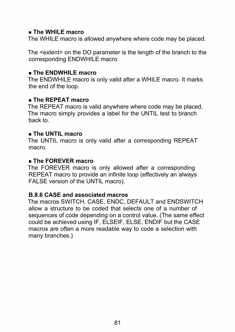
81
The WHILE macroThe WHILE macro is allowed anywhere where code may be placed.
The <extent> on the DO parameter is the length of the branch to thecorresponding ENDWHILE macro.
The ENDWHILE macroThe ENDWHILE macro is only valid after a WHILE macro. It marksthe end of the loop.
The REPEAT macroThe REPEAT macro is valid anywhere where code may be placed.The macro simply provides a label for the UNTIL test to branchback to.
The UNTIL macroThe UNTIL macro is only valid after a corresponding REPEATmacro.
The FOREVER macroThe FOREVER macro is only allowed after a correspondingREPEAT macro to provide an infinite loop (effectively an alwaysFALSE version of the UNTIL macro).
B.8.6 CASE and associated macrosThe macros SWITCH, CASE, ENDC, DEFAULT and ENDSWITCHallow a structure to be coded that selects one of a number ofsequences of code depending on a control value. (The same effectcould be achieved using IF, ELSEIF, ELSE, ENDIF but the CASEmacros are often a more readable way to code a selection withmany branches.)

82
The general structure is:
SWITCH<length> <ea>{ CASE[<extent>] <ea> . . [ ENDC[<extent>] ]}[ DEFAULT . . [ENDC[<extent>] ]]
ENDSWITCH
The SWITCH macroThe SWITCH macro introduces a set of CASE options. It is allowedanywhere where code is allowed. The <length> is the length of allthe comparisons generated by all the relevant CASE macros.
The <ea> is the control variable which is used to select the CASE tobe executed.
The CASE macroThe CASE macro introduces an option. The CASE macro is allowedonly after a previous CASE, SWITCH or ENDC macro.
The <extent> on the CASE macro is the length of the branch to thenext CASE, DEFAULT or ENDSWITCH macro.
The code following the CASE macro up to the next ENDC macro isexecuted if the control variable is equal to the <ea>, after which theprogram resumes at the ENDSWITCH macro.
The ENDC macroThe ENDC macro is allowed only after a previous CASE orDEFAULT macro. The <extent> is the length of the branch to theENDSWITCH macro.

83
The DEFAULT macroThe DEFAULT macro is allowed only after a previous CASE orENDC macro. Its purpose is to provide the default option if allprevious options have not been satisfied.
The ENDSWITCH macroThe ENDSWITCH macro is only allowed after a previous ENDC,DEFAULT, CASE or SWITCH macro. Its purpose is to terminate theSWITCH structure.
B.8.7 Stack handlingThe PUSH$ and POP$ macros save values (usually registers) onthe A7 stack and restore them.
PUSH$[<length>] <ea>
generates:
MOVE<length> <ea>, – (A7)
and:
POP$[<length>] <ea>
generates:
MOVE<length> (A7)+ ,<ea>
B.8.8. STRINGS definition
<name> STRING$ '<string>'
creates a string in standard format consisting of the two-byte lengthof the string followed by the characters of the string. The parametershould be enclosed in quotes, e.g.:
FILE STRING$ 'MDVI_MY_Fl LE'
and if it includes spaces, commas etc. the curly brackets must alsobe used, e.g.:
STRING1 STRING$ {'This is a string'}STRING2 STRING$ {'A line followed by a line feed',$0A}

84
B.8.9 SUBROUTINE$ and associated macrosThe macros SUBROUTINE$ and END$ are useful to mark the startand end of subroutines. If a subroutine needs to preserve a set ofregisters then these macros will generate the necessary MOVEMinstructions; END$ also generates RTS.
In addition these macros will check that structure macros usedinside the subroutine have been terminated properly, e.g. a missingENDIF will cause a warning message when the END$ is processed.
SUBROUTINE$ <name>[,<multireg>] . . .END$[<name>]
The <name> is generated as a label by SUBROUTINE$ so that itcan be used as the destination of JSR and BSR instructions. If a<name> is coded on the END$ macro it is checked to see that itmatches the previous SUBROUTINE$ and an error message isgenerated if not.
B.8.10 Macros for calling QdosThe following macros are provided for making calls to Qdos:
QDOSMT$ <function name>
is used for manager traps and generates:
MOVEQ #<function name>, D0TRAP #1
and:
QDOSOC$ <function name>
is used for open and close channel calls and generates:
MOVEQ #<function name>, D0TRAP #2

85
and:
QDOSIO$ <function name>
is used for other input/output operations and generates:
MOVEQ #<function name>,D0TRAP #3
In each case the <function name>s needed for the various Qdostraps are provided in the parameter files supplied with the macroassembler, so if you INCLUDE the necessary parameter files andmacro library you can write Qdos calls like this:
MOVEQ #-1,D1 current jobCLR.L D3 old, exclusiveLEA FILENAME,A0 name ofQDOSOC$ IO.OPEN file to open..FILENAME STRING$ ‘MDV1_INPUT_FILE’

86
Appendix C – Error and warningMessagesThis appendix lists the error and warning messages which can beproduced by the assembler in numerical order.
C.1 Error messages 00 – unknown instruction/directive
An unknown symbol has been used where an instruction or directive is expected in the operation field.
01– illegal line after OFFSET Instructions and directives which generate code (DC, DCB) are not allowed in the dummy section defined by the OFFSET directive. Return to a SECTION before instructions or data.
02 – syntax error in instruction field The operation field does not contain a <symbol>.
03 – redefined symbol The symbol has already been defined earlier in the assembly. The first definition of the symbol will be used; further definitions will just produce this error message.
04 – phasing error This is an assembler internal error – it should only happen if the source file has changed between pass 1 of the assembler and pass 2.
05 – missing operand The instruction requires two operands, and only one has been coded.
06 –syntax error The line contains a syntax error which has left the assembler with very little idea of what was meant.

87
07 – syntax error in expression or operand The assembler is expecting an expression or other instruction operand but does not understand what it has found.
08 – multireg, cannot mix Dreg & Areg Data registers and address registers may not be combined in a range: eg D3 – A4 is illegal.
09 – multireg, bad sequence The registers in a range must be in increasing order— eg D5 – D2 is illegal.
0A – unmatched open bracket There are too many open brackets in the expression: unmatched open brackets are 'closed' at the end of the expression.
0B – unmatched close bracket There are too many close brackets in the expression: unmatched close brackets are ignored.
0C –expression too complicated An expression is limited to five levels of nested brackets. Certain combinations of operators can cause this error with fewer brackets – eg when low priority operators are followed by high priority operators.
0D – expression: string too long When a string is used as a term in an expression, it may be up to four characters long.
0E – internal error – expression stack underflow This is an internal assembler error which should never occur.
0F – invalid character Some characters such as " ? ^ = have no meaning to the assembler. They may only be used within strings. The character is ignored.
11– no digits in number A number is expected (eg after $ or %) but no digits are present.

88
12 – number overflow The number is too large and will not fit in 32 bits.
13 – string terminator missing A string must be terminated by a quote character.
14 – relocatable value not allowed here Some addressing modes and directives require absolute values.
15 – multiply overflow in expression A multiply overflow error occurred while evaluating an expression.
16 – divide by 0 or divide underflow A divide error occurred during evaluation of an expression.
18 – -ve value illegal Some directives (eg DS) can accept a zero or positive number, but a negative value is illegal.
19 – value must be +ve nonzero Some instructions or directives require a positive, non-zero, value (eg the,number of elements for DCB).
1A – value out of range This is a general purpose message for any value out of range in instructions or directives. The actual value range depends on context – read again the description of the instruction or directive involved.
1D – size not allowed on directive Most directives do not accept a size extension: the only ones that do allow a size are DC, DCB & DS.
1E – invalid size The size specified on the instruction or directive is not legal.
1F– size .B illegal for Areg Byte operations on address registers are not allowed.

89
20 – label illegal on this directive Many directives (eg INCLUDE, SECTION, LIST, PAGE) do not accept a label.
21 – too many errors If a line has more than ten errors or warnings, only the first ten are printed, followed by this message.
22 – invalid operand(s) for this instruction The operand(s) specified are not valid for the instruction. Check the rules for the instruction you are using in a 68000 manual. If one of the operands to the instruction is an "effective address" this error can mean that the actual addressing mode specified is not legal.
The assembler will try to point the error flag (the vertical bar character) at the invalid operand, but as the assembler may not even know (in the case of a generic mnemonic) which instruction you meant it will get this wrong sometimes.
23 – undefined symbol The symbol has not been defined in the assembly.
24 – forward reference not allowed here Many directives do not allow a forward reference.
25 – short branch out of range BRA.S (or some other Branch.S) has been coded but the destination is more than 128 bytes away.
26 – long branch out of range The destination of a long branch must be within 32k.
27 – value must be simple relocatable The expression should be simple relocatable: absolute or complex values are illegal (e.g. in the destination of a branch instruction).
28 – value must not be complex Absolute and simple relocatable expressions can generally be used as addresses but a complex relocatable value is illegal.

90
29 – this directive must have a label EQU,REG, MACRO and MACLAB require a label
2A – unable to generate position independent code here Normally if a label or expression is used to specify an address in an instruction, a PC-relative addressing mode is generated to produce position independent code. This is not an alterable addressing mode, so this error message is generated when an alterable addressing mode is required.
2B – short branch to next instruction – NOP generated A short branch to the next instruction is not a legal 68000 opcode. The assembler generates a NOP instruction in this case.
2E – not allowed with –NOLINK option Many of the directives relating to relocation and linking may not be used if the –NOLINK option has been coded on the command line.
2F – not allowed in this context This line is not allowed here because the context is wrong; this usually means that the wrong sort of location counter is in use, for example instructions are not allowed in a COMMON section. The most frequent cause of this error message is forgetting to code an appropriate SECTION directive.
30 – same name used in SECTION and COMMON You cannot have ordinary SECTIONs and COMMON sections with the same name.
31 – wrong relocation for PC-relative address The assembler is trying to generate a PC-relative address but can't because the relocation factor of the instruction does not match that of the destination (e.g. a reference to a relocatable address from an instruction which follows an ORG).
32 – COMMON block name cannot be used here The name of a COMMON block can only be used in a very restricted set of circumstances; this isn't one of them.

91
33 – same name used in, SECTION and COMMON You cannot have ordinary SECTIONS and COMMON sections with the same name.
34 – illegal expression for RORG The <expr> in a RORG directive is not absolute and is not simple relocatable with respect to the current section (or has something else wrong with it). See the description of RORG for the full list of restrictions which apply to this <expr>.
35 – references to external symbols not allowed Some directives need to know the actual values of their operands at assembly time and these do not therefore permit external symbols (those whose names appear in XREF directives) to be coded.
36 – expressions needing linking not allowed In some circumstances expressions whose final value must be determined by the linker are not allowed; replace the expression with one whose value is known to the assembler.
37 – this symbol invalid in XDEF There are various restrictions on the type of symbol that may be named in an XDEF directive. See the description of the XDEF directive for full details.
39 – label not found for GOTO The label specified as the destination of the IFSTR, IFNUM or GOTO directive is not defined on a MACLAB directive in the current macro.
3A – not currently in a macro This directive or function may only be used within a macro.
3B – user generated error An ERROR directive was processed.
3C – expression does not result in a value An expression used at this point must evaluate to an absolute value involving no forward references or relocation bases or external symbols.

92
3D – illegal parameter number for .PARM The value of the expression lies outside the range 1 to .NPARMS.
3E – unexpected end of file after continuation line The last line in a file ended in a backslash ' \' and a continuation line was expected.
3F – MACRO name same as instruction or directive You cannot define a macro with the same name as an instruction or an assembler directive.
40 – built-in function not allowed here A function call is not allowed here (e.g. as the parameter to the .DEF function).
C.2 Warning messages 50 – size missing, W assumed
No size was specified on an index register.
51 – size missing, W assumed The instruction or directive can have more than one size, but no size was specified. 52 – multiply defined register
A register has been multiply defined in a multiregister sequence(eg A0/D1/D0–D3 has D1 multiply defined).
53 – decimal number goes negative A decimal number has a value between $80000000 and $FFFFFFFF. This is a perfectly valid number with which to do unsigned arithmetic, but it is an overflow if the programmer was intending to use it for signed arithmetic. As the assembler does not know what the programmer wants to do with the number it produces this warning.
55 – value will be sign extended to 32 bits In MOVEQ the expression is between $80 and $FF so it will be sign-extended to a 32-bit negative value.

93
56 – nonstandard use of this instruction This warning is printed when an instruction is used in a nonstandard manner which may be a bug (eg LINK with a positive displacement).
57 – branch could be short A forwards branch or a branch with an explicit .L is within 128 bytes range and could be a short branch.
58 – END directive missing An END directive is expected at the end of the assembly, but endof-file was found instead.
59 – XREF.S value will probably overflow when linked An expression is of type XREF.S and is being placed in a 1-byte field. Depending on the actual value of the external symbols when the program is linked this may or may not cause an overflow.
5A – XREF.L value will probably overflow when linked An expression is of type XREF.L and is being placed in a 1– or 2–byte field. Depending on the actual value of the external symbols when the program is linked this may or may not cause an overflow.
5B – ENDM directive missing after macro definition End of file was found while processing a macro definition. This probably indicates that you omitted an ENDM directive or coded it in such a way that it could not be recognised (recall that ENDM must not be generated by variable substitution).
5C – ENDM directive missing while expanding a macro The assembler ran off the end of the file while expanding a macro.
5D – user generated warning A WARNING directive was processed.
5E – multiply defined symbol Either the same name is used for two different macros or the same name is declared twice in LOCAL directives in the same macro. In both cases the first definition takes effect and subsequent definitions are ignored.

94
C.3 Operating system errorsWhen the assembler gets an error code from Qdos it usually givesup completely, first displaying a message relating to the error on thescreen.
Most Qdos errors relate to particular input or output files or devicesand the file or device name involved is displayed as part of themessage wherever possible.
In the case of a serious error (such as bad Microdrive tape)affecting an input source file the assembler does not however tellyou which of the various source (e.g. INCLUDEd) files is involved.
If the assembler is run with EXEC_W the error code is passed backto the EXEC_W command which will display another error message.