Embed Size (px)
Citation preview
QE108: ELECTRICITY Electrical Measurements Laboratory Report
Reg. No:
Name :
Group No:
Year :

Session 1: Experiment 1
QE108: Electricity – Laboratory sessions
Permanent Magnet Moving Coil Galvanometer Construction
DATE:
OBJECTIVE: To study the construction and principle of operation of a Permanent Magnet Moving Coil (PMMC) Galvanometer
APPARATUS: Opened PMMC galvanometer
RELATED KNOWLEDGE
Derive an expression relating the deflection ( )θ of the indicator of a PMMC and the current ( )i flowing through it.
N SX
θ
r
X
θ
r
Figure 1: Galvanometer Principle
LABORATORY WORK: i. Observe the opened Galvanometer provided and identify the main
components. ii. Sketch the Galvanometer indicating all the major components.
iii. Briefly describe the function of each component on the same sketch.
Figure 2: Sketch of the Galvanometer
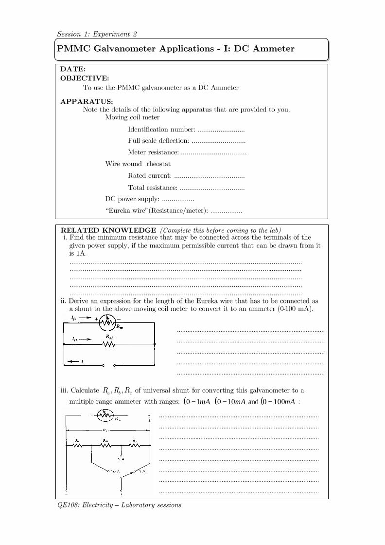
Session 1: Experiment 2
QE108: Electricity – Laboratory sessions
PMMC Galvanometer Applications - I: DC Ammeter
DATE: OBJECTIVE: To use the PMMC galvanometer as a DC Ammeter APPARATUS: Note the details of the following apparatus that are provided to you. Moving coil meter
Identification number: .........................
Full scale deflection: ............................
Meter resistance: ..................................
Wire wound rheostat
Rated current: .....................................
Total resistance: ..................................
DC power supply: .................
“Eureka wire”(Resistance/meter): .................
RELATED KNOWLEDGE (Complete this before coming to the lab) i. Find the minimum resistance that may be connected across the terminals of the
given power supply, if the maximum permissible current that can be drawn from it is 1A. .......................................................................................................................... .......................................................................................................................... .......................................................................................................................... .......................................................................................................................... ..........................................................................................................................
ii. Derive an expression for the length of the Eureka wire that has to be connected as a shunt to the above moving coil meter to convert it to an ammeter (0-100 mA). IfsIfs
iii. Calculate cba RRR ,, of universal shunt for converting this galvanometer to a
multiple-range ammeter with ranges: ( ) ( ) ( )mAmAmA 1000 and 100 10 −−− :
.....................................................................................
.....................................................................................
.....................................................................................
.....................................................................................
.....................................................................................
.....................................................................................
............................................................................................
............................................................................................
............................................................................................
............................................................................................
............................................................................................
............................................................................................
............................................................................................
.......................................................................... ..................
Session 1: Experiment 2
QE108: Electricity – Laboratory sessions
Figure L1-1: Construction of a moving coil galvanometer
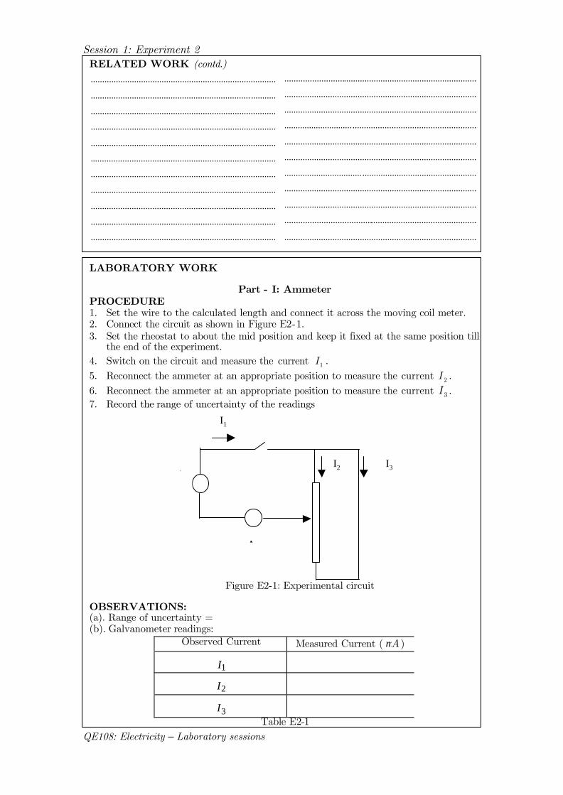
LABORATORY WORK
Part - I: Ammeter PROCEDURE 1. Set the wire to the calculated length and connect it across the moving coil meter. 2. Connect the circuit as shown in Figure E2-1. 3. Set the rheostat to about the mid position and keep it fixed at the same position till
the end of the experiment. 4. Switch on the circuit and measure the current 1I . 5. Reconnect the ammeter at an appropriate position to measure the current 2I . 6. Reconnect the ammeter at an appropriate position to measure the current 3I . 7. Record the range of uncertainty of the readings
+E -
A
I1
I2 I3
Figure E2-1: Experimental circuit
OBSERVATIONS: (a). Range of uncertainty = (b). Galvanometer readings:
Observed Current Measured Current ( Aµ )
1I
2I
3I
Table E2-1
RELATED WORK (contd.)
.................................................................................
...................................................................... ...........
.................................................................................
.................................................................................
.................................................................................
.................................................................................
.................................................................................
.................................................................................
.................................................................................
.................................................................................
.................................................................................
....................................................................................
....................................................................................
....................................................................................
.............................. ......................................................
....................................................................................
....................................................................................
.................................. ..................................................
....................................................................................
....................................................................................
....................................................................................
....................................................................................
Session 1: Experiment 2
QE108: Electricity – Laboratory sessions
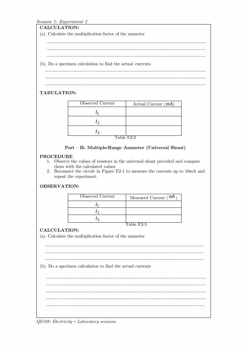
CALCULATION: (a). Calculate the multiplication factor of the ammeter (b). Do a specimen calculation to find the actual currents TABULATION:
Observed Current Actual Current (mA)
1I
2I
3I
Table E2-2
Part – II: Multiple-Range Ammeter (Universal Shunt) PROCEDURE
1. Observe the values of resistors in the universal shunt provided and compare them with the calculated values
2. Reconnect the circuit in Figure E2-1 to measure the currents up to 10mA and repeat the experiment.
OBSERVATION:
Observed Current Measured Current ( mA )
1I
2I
3I
Table E2-3 CALCULATION: (a). Calculate the multiplication factor of the ammeter (b). Do a specimen calculation to find the actual currents
................ ...............................................................................................................................................
...............................................................................................................................................................
...............................................................................................................................................................
...............................................................................................................................................................
................................................................................................................................ ...............................
...............................................................................................................................................................
..................
.............................................. ...................................................................................................................
............................................................................................................................................. ....................
.................................................................................................................................................................
......................................................................... .......................................................................................
................................................................................................................................................................
................................................................................................................................................................
......................................................................................................... .......................................................
...............................................................................................................................................................
Session 1: Experiment 2
QE108: Electricity – Laboratory sessions
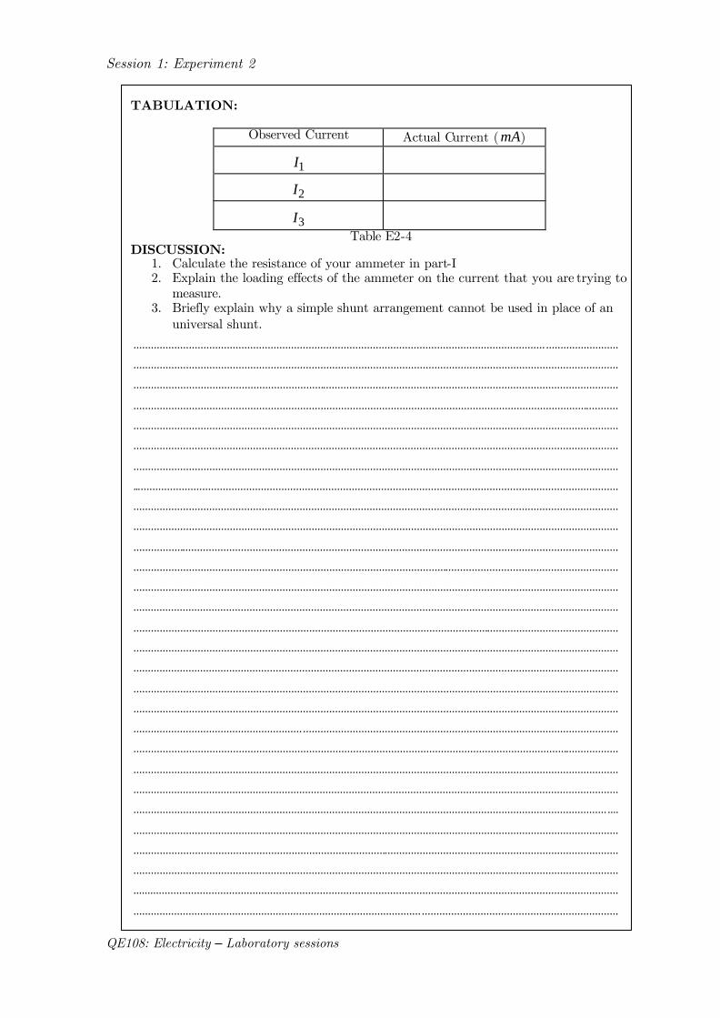
TABULATION:
Observed Current Actual Current (mA)
1I
2I
3I
Table E2-4 DISCUSSION:
1. Calculate the resistance of your ammeter in part-I 2. Explain the loading effects of the ammeter on the current that you are trying to
measure. 3. Briefly explain why a simple shunt arrangement cannot be used in place of an
universal shunt. ............................................................................................................................................. .........................
......................................................................................................................................................................
......................................................................................................................................................................
......................................................................................................................................................................
......................................................................................................................................................................
......................................................................................................................................................................
......................................................................................................................................................................
......................................................................................................................................................................
......................................................................................................................................................................
......................................................................................................................................................................
......................................................................................................................................................................
......................................................................................................................................................................
......................................................................................................................................................................
......................................................................................................................................................................
......................................................................................................................................................................
......................................................................................................................................................................
......................................................................................................................................................................
......................................................................................................................................................................
......................................................................................................................................................................
.......................................................... ............................................................................................................
......................................................................................................................................................................
......................................................................................................................................................................
......................................................................................................................................................................
.................................................................................................................................................................. ....
......................................................................................................................................................................
......................................................................................................................................................................
......................................................................................................................................................................
......................................................................................................................................................................
................................................................................................... ...................................................................
......................................................................................................................................................................
Session 1: Experiment 3
QE108: Electricity – Laboratory sessions
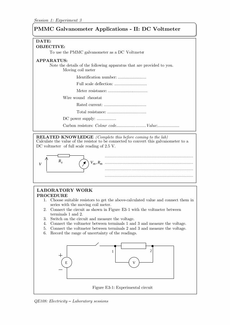
PMMC Galvanometer Applications - II: DC Voltmeter
DATE: OBJECTIVE: To use the PMMC galvanometer as a DC Voltmeter APPARATUS: Note the details of the following apparatus that are provided to you. Moving coil meter
Identification number: .........................
Full scale deflection: ............................
Meter resistance: ..................................
Wire wound rheostat
Rated current: .....................................
Total resistance: ..................................
DC power supply: .................
Carbon resistors: Colour code..........................Value:...................
RELATED KNOWLEDGE (Complete this before coming to the lab) Calculate the value of the resistor to be connected to convert this galvanometer to a DC voltmeter of full scale reading of 2.5 V.
mm RV ,sRV
LABORATORY WORK
PROCEDURE 1. Choose suitable resistors to get the above-calculated value and connect them in
series with the moving coil meter. 2. Connect the circuit as shown in Figure E3-1 with the voltmeter between
terminals 1 and 2. 3. Switch on the circuit and measure the voltage. 4. Connect the voltmeter between terminals 1 and 3 and measure the voltage. 5. Connect the voltmeter between terminals 2 and 3 and measure the voltage. 6. Record the range of uncertainty of the readings.
Figure E3-1: Experimental circuit
.....................................................................................
.....................................................................................
.....................................................................................
.....................................................................................
.....................................................................................
E
1 2
V
Session 1: Experiment 3
QE108: Electricity – Laboratory sessions
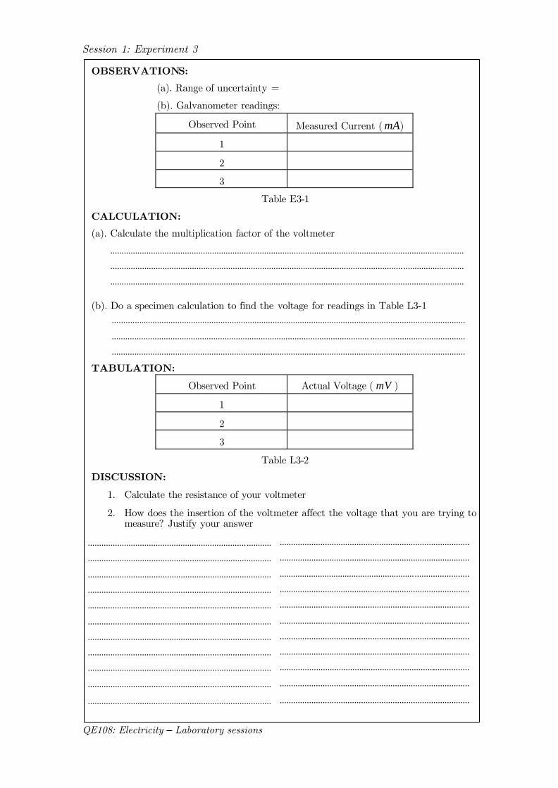
OBSERVATIONS:
(a). Range of uncertainty =
(b). Galvanometer readings:
Observed Point Measured Current ( mA)
1
2
3
Table E3-1
CALCULATION:
(a). Calculate the multiplication factor of the voltmeter
(b). Do a specimen calculation to find the voltage for readings in Table L3-1
TABULATION:
Observed Point Actual Voltage ( mV )
1
2
3
Table L3-2
DISCUSSION:
1. Calculate the resistance of your voltmeter
2. How does the insertion of the voltmeter affect the voltage that you are trying to measure? Justify your answer
............................................................................................................................................................
................................................................................................................................. ...........................
............................................................................................................................................................
............................................................................................................................................................
.................................................................................................................. ..........................................
............................................................................................................................................................
...................................................................... ...........
.................................................................................
.................................................................................
.................................................................................
.................................................................................
.................................................................................
.................................................................................
.................................................................................
.................................................................................
.................................................................................
.................................................................................
....................................................................................
....................................................................................
............................................................ ........................
....................................................................................
....................................................................................
................................................................ ....................
....................................................................................
....................................................................................
....................................................................................
....................................................................................
....................................................................................
Session 2: Experiment 1
QE108: Electricity – Laboratory sessions
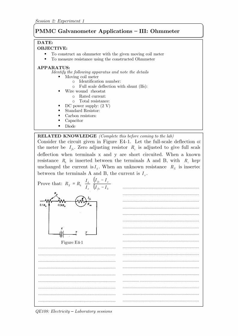
PMMC Galvanometer Applications – III: Ohmmeter
DATE: OBJECTIVE: § To construct an ohmmeter with the given moving coil meter § To measure resistance using the constructed Ohmmeter
APPARATUS: Identify the following apparatus and note the details
§ Moving coil meter o Identification number: o Full scale deflection with shunt (Ifs):
§ Wire wound rheostat o Rated current: o Total resistance:
§ DC power supply: (2 V) § Standard Resistor: § Carbon resistors: § Capacitor § Diode
RELATED KNOWLEDGE (Complete this before coming to the lab) Consider the circuit given in Figure E4-1. Let the full-scale deflection of the meter be fsI . Zero adjusting resistor zR is adjusted to give full scale deflection when terminals x and y are short circuited. When a known resistance kR is inserted between the terminals A and B, with zR kept unchanged the current is kI . When an unknown resistance XR is inserted between the terminals A and B, the current is xI .
Prove that: ( )( )kfs
xfs
x
kkX II
II
II
RR−
−⋅⋅=
.......................................................................
.......................................................................
.......................................................................
.......................................................................
.......................................................................
.......................................................................
.......................................................................
.......................................................................
........................................... ............................
.......................................................................
.......................................................................
.......................................................................
.......................................................................
.......................................................................
................ .......................................................
.......................................................................
.......................................................................
.......................................................................
Figure E4-1
........................................................................
........................................................................
........................................................................
........................................................................
........................................................................
........................................................................
........................................................................
........................................................................
........................................................................
Session 2: Experiment 1
QE108: Electricity – Laboratory sessions
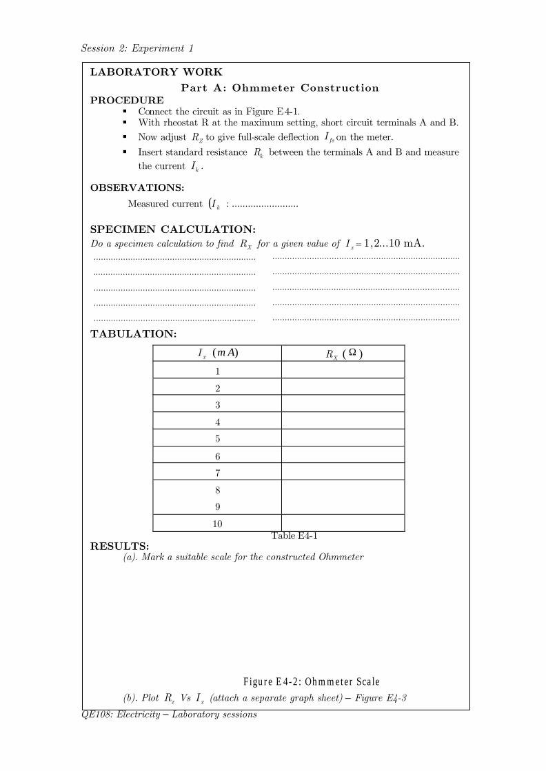
LABORATORY WORK
Part A: Ohmmeter Construction
PROCEDURE § Connect the circuit as in Figure E4-1. § With rheostat R at the maximum setting, short circuit terminals A and B. § Now adjust ZR to give full-scale deflection fsI on the meter. § Insert standard resistance kR between the terminals A and B and measure
the current kI .
OBSERVATIONS:
Measured current ( )kI : .........................
SPECIMEN CALCULATION: Do a specimen calculation to find XR for a given value of xI = 1,2...10 mA.
TABULATION:
xI (mA) XR ( Ω )
1
2
3
4
5
6
7
8
9
10 Table E4-1
RESULTS: (a). Mark a suitable scale for the constructed Ohmmeter
Figure E 4-2: Ohmmeter Scale
(b). Plot xR Vs xI (attach a separate graph sheet) – Figure E4-3
..................................................................
..................................................................
..................................................................
..................................................................
..................................................................
............................................................................
............................................................................
............................................................................
............................................................................
............................................................................
............................................................................
Session 2: Experiment 1
QE108: Electricity – Laboratory sessions
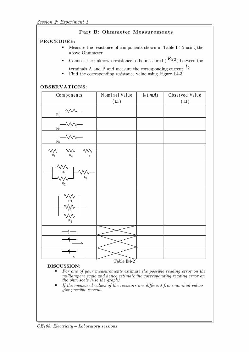
OBSERVATIONS:
Components Nominal Value ( Ω )
Ix ( mA) Observed Value ( Ω )
R1
R2
R3
R R R1 2 3
R1
R2
R3
R1
R2
R3
Table E4-2 DISCUSSION: § For one of your measurements estimate the possible reading error on the
milliampere scale and hence estimate the corresponding reading error on the ohm scale (use the graph)
§ If the measured values of the resistors are different from nominal values give possible reasons.
Part B: Ohmmeter Measurements
PROCEDURE: § Measure the resistance of components shown in Table L4-2 using the
above Ohmmeter
§ Connect the unknown resistance to be measured ( 2XR ) between the
terminals A and B and measure the corresponding current 2I § Find the corresponding resistance value using Figure L4-3.
Session 2: Experiment 2
QE108: Electricity – Laboratory sessions
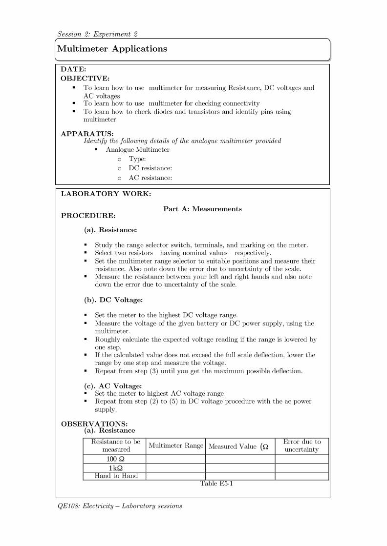
Multimeter Applications
DATE: OBJECTIVE: § To learn how to use multimeter for measuring Resistance, DC voltages and
AC voltages § To learn how to use multimeter for checking connectivity § To learn how to check diodes and transistors and identify pins using
multimeter APPARATUS: Identify the following details of the analogue multimeter provided
§ Analogue Multimeter o Type: o DC resistance: o AC resistance:
LABORATORY WORK:
Part A: Measurements PROCEDURE:
(a). Resistance:
§ Study the range selector switch, terminals, and marking on the meter. § Select two resistors having nominal values respectively. § Set the multimeter range selector to suitable positions and measure their
resistance. Also note down the error due to uncertainty of the scale. § Measure the resistance between your left and right hands and also note
down the error due to uncertainty of the scale. (b). DC Voltage:
§ Set the meter to the highest DC voltage range. § Measure the voltage of the given battery or DC power supply, using the
multimeter. § Roughly calculate the expected voltage reading if the range is lowered by
one step. § If the calculated value does not exceed the full scale deflection, lower the
range by one step and measure the voltage. § Repeat from step (3) until you get the maximum possible deflection.
(c). AC Voltage:
§ Set the meter to highest AC voltage range § Repeat from step (2) to (5) in DC voltage procedure with the ac power
supply. OBSERVATIONS:
(a). Resistance
Resistance to be measured Multimeter Range Measured Value ( )Ω
Error due to uncertainty
Ω 100 Ωk 1
Hand to Hand Table E5-1
Session 2: Experiment 2
QE108: Electricity – Laboratory sessions
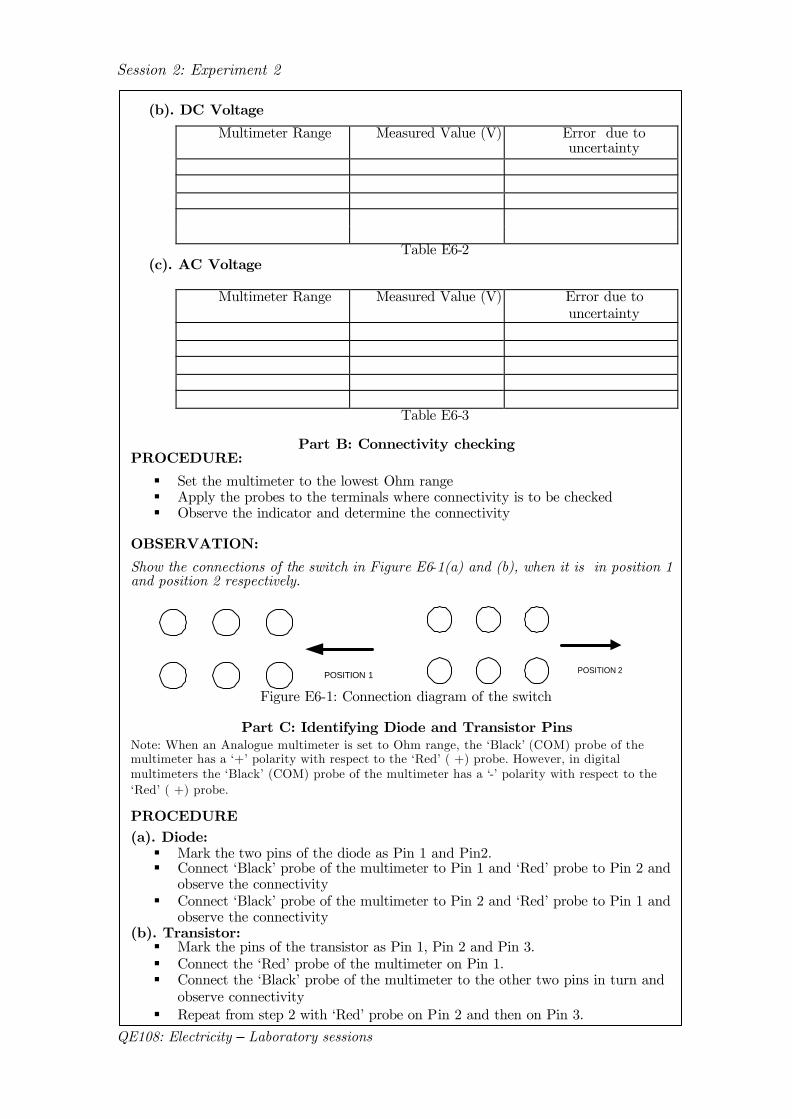
(b). DC Voltage
Multimeter Range Measured Value (V) Error due to uncertainty
Table E6-2 (c). AC Voltage
Multimeter Range Measured Value (V) Error due to uncertainty
Table E6-3
Part B: Connectivity checking PROCEDURE:
§ Set the multimeter to the lowest Ohm range § Apply the probes to the terminals where connectivity is to be checked § Observe the indicator and determine the connectivity
OBSERVATION: Show the connections of the switch in Figure E6-1(a) and (b), when it is in position 1 and position 2 respectively.
POSITION 1 POSITION 2
Figure E6-1: Connection diagram of the switch
Part C: Identifying Diode and Transistor Pins
Note: When an Analogue multimeter is set to Ohm range, the ‘Black’ (COM) probe of the multimeter has a ‘+’ polarity with respect to the ‘Red’ ( +) probe. However, in digital multimeters the ‘Black’ (COM) probe of the multimeter has a ‘-’ polarity with respect to the ‘Red’ ( +) probe. PROCEDURE
(a). Diode: § Mark the two pins of the diode as Pin 1 and Pin2. § Connect ‘Black’ probe of the multimeter to Pin 1 and ‘Red’ probe to Pin 2 and
observe the connectivity § Connect ‘Black’ probe of the multimeter to Pin 2 and ‘Red’ probe to Pin 1 and
observe the connectivity (b). Transistor: § Mark the pins of the transistor as Pin 1, Pin 2 and Pin 3. § Connect the ‘Red’ probe of the multimeter on Pin 1. § Connect the ‘Black’ probe of the multimeter to the other two pins in turn and
observe connectivity § Repeat from step 2 with ‘Red’ probe on Pin 2 and then on Pin 3.
Session 2: Experiment 2
QE108: Electricity – Laboratory sessions
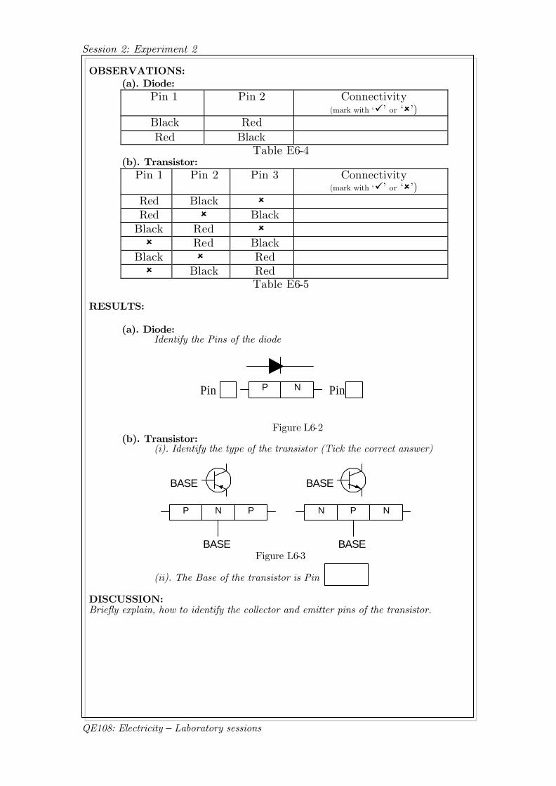
OBSERVATIONS: (a). Diode:
Pin 1 Pin 2 Connectivity (mark with ‘ü’ or ‘û’)
Black Red Red Black
Table E6-4 (b). Transistor:
Pin 1 Pin 2 Pin 3 Connectivity (mark with ‘ü’ or ‘û’)
Red Black û Red û Black
Black Red û û Red Black
Black û Red û Black Red
Table E6-5
RESULTS:
(a). Diode: Identify the Pins of the diode
P NPin Pin
Figure L6-2
(b). Transistor: (i). Identify the type of the transistor (Tick the correct answer)
PNP
BASE
BASE
NPN
BASE
BASE
Figure L6-3
(ii). The Base of the transistor is Pin
DISCUSSION: Briefly explain, how to identify the collector and emitter pins of the transistor.
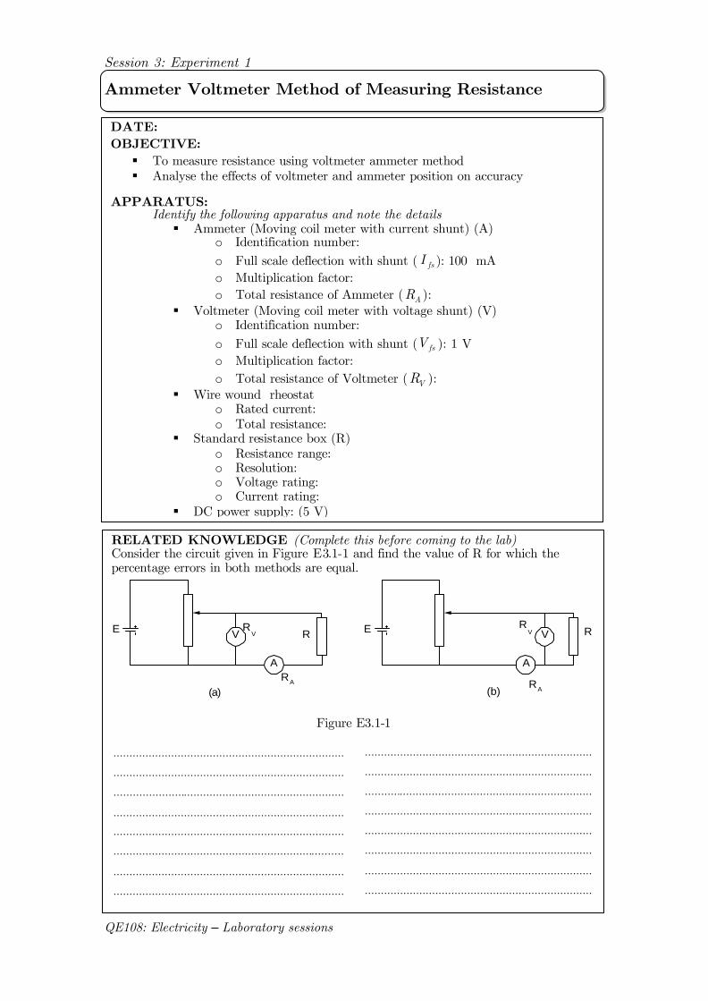
Session 3: Experiment 1
QE108: Electricity – Laboratory sessions
Ammeter Voltmeter Method of Measuring Resistance
DATE: OBJECTIVE: § To measure resistance using voltmeter ammeter method § Analyse the effects of voltmeter and ammeter position on accuracy
APPARATUS: Identify the following apparatus and note the details
§ Ammeter (Moving coil meter with current shunt) (A) o Identification number: o Full scale deflection with shunt ( fsI ): 100 mA o Multiplication factor: o Total resistance of Ammeter ( AR ):
§ Voltmeter (Moving coil meter with voltage shunt) (V) o Identification number: o Full scale deflection with shunt ( fsV ): 1 V o Multiplication factor: o Total resistance of Voltmeter ( VR ):
§ Wire wound rheostat o Rated current: o Total resistance:
§ Standard resistance box (R) o Resistance range: o Resolution: o Voltage rating: o Current rating:
§ DC power supply: (5 V)
RELATED KNOWLEDGE (Complete this before coming to the lab) Consider the circuit given in Figure E3.1-1 and find the value of R for which the percentage errors in both methods are equal.
E
A
V R E
A
V RR
VRV
RA
RA
(a) (b)
Figure E3.1-1
.......................................................................
.......................................................................
.......................................................................
.......................................................................
.......................................................................
.......................................................................
.......................................................................
.......................................................................
........................................... ............................
........................................................................
........................................................................
........................................................................
........................................................................
........................................................................
........................................................................
........................................................................
........................................................................
Session 3: Experiment 1
QE108: Electricity – Laboratory sessions
..................................................................
..................................................................
..................................................................
..................................................................
..................................................................
..................................................................
..................................................................
..................................................................
..................................................................
............................................................................
............................................................................
............................................................................
............................................................................
............................................................................
............................................................................
............................................................................
............................................................................
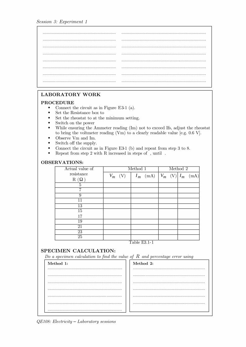
LABORATORY WORK
PROCEDURE § Connect the circuit as in Figure E3-1 (a). § Set the Resistance box to § Set the rheostat to at the minimum setting. § Switch on the power § While ensuring the Ammeter reading (Im) not to exceed Ifs, adjust the rheostat
to bring the voltmeter reading (Vm) to a clearly readable value [e.g. 0.6 V]. § Observe Vm and Im. § Switch off the supply. § Connect the circuit as in Figure E3-1 (b) and repeat from step 3 to 8. § Repeat from step 2 with R increased in steps of , until .
OBSERVATIONS: Method 1 Method 2 Actual value of
resistance R (Ω ) mV (V) mI (mA) mV (V) mI (mA)
5 7 9 11 13 15 17 19 21 23 25
Table E3.1-1
SPECIMEN CALCULATION: Do a specimen calculation to find the value of R and percentage error using
Method 1: ...................................................................
...................................................................
...................................................................
...................................................................
..................................................... ..............
...................................................................
...................................................................
Method 2: .................................................................
.................................................................
.................................................................
.................................................................
.................................................................
.................................................................
.................................................................
Session 3: Experiment 1
QE108: Electricity – Laboratory sessions
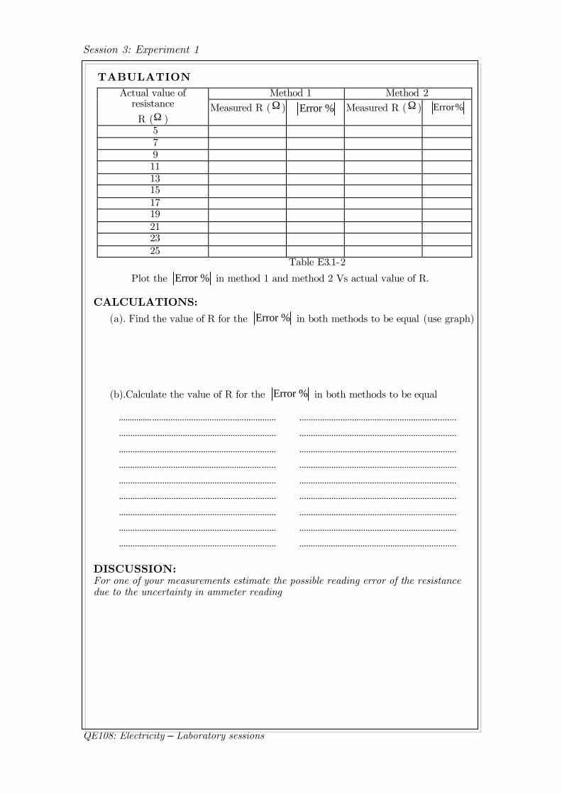
TABULATION
Method 1 Method 2 Actual value of resistance R (Ω )
Measured R (Ω ) %Error Measured R (Ω ) %Error
5 7 9 11 13 15 17 19 21 23 25
Table E3.1-2
Plot the %Error in method 1 and method 2 Vs actual value of R.
CALCULATIONS: (a). Find the value of R for the %Error in both methods to be equal (use graph)
(b).Calculate the value of R for the %Error in both methods to be equal
DISCUSSION: For one of your measurements estimate the possible reading error of the resistance due to the uncertainty in ammeter reading
.....................................................................
.....................................................................
.....................................................................
............................................................... ......
.....................................................................
.....................................................................
.....................................................................
.....................................................................
.....................................................................
.....................................................................
.....................................................................
.....................................................................
.....................................................................
.....................................................................
.....................................................................
.....................................................................
.....................................................................
.....................................................................
Session 3: Experiment 2
QE108: Electricity – Laboratory sessions
Megohm Meter (Megger)
DATE: OBJECTIVE: § To learn how to use the “Megger” Insulation tester to measure the resistance
of various insulations § To measure the insulation resistance of a wiring system
APPARATUS: Identify the following apparatus and note the details
§ “Megger” insulation tester: (500 V/ 1000 M , Hand driven type)
RELATED KNOWLEDGE (Complete this before coming to the lab) Draw the internal circuitry of a Megohm meter and briefly explain its operation
..................................................................................
.................................................... ............................
..................................................................................
................................................................................
..................................................................................
......................................................................... .......
..................................................................................
................................................................................
..................................................................................
................................................................................
..................................................................................
................................................................................
..................................................................................
................................................................................ Figure E3.2-1: Internal Circuitry of a Megger
LABORATORY WORK
Part A: Resistance of Insulation Materials PROCEDURE § Measure the insulation resistance of the materials provided. § Measure the insulation resistance between
o Phase-Neutral o Phase-Insulating cover o Neutral-Insulating cover of the service wire provided.
§ Measure the insulation resistance between o Primary-Secondary winding o Primary-Earth o Secondary-Earth terminals of the each transformer provided and
identify the faulty windings (if any)
Session 3: Experiment 2
QE108: Electricity – Laboratory sessions
OBSERVATIONS: (a). Resistance of insulation materials
Material Insulation Resistance / (M Ω ) Thin metal Thick metal
Plastic Thin Hardboard Thick Hardboard
Table E3.2-1 (b). Resistance of the service wire
Terminals Insulation Resistance / (M Ω ) Phase-Neutral Phase-Insulating cover Neutra-Insulating cover
Table E3.2-2 (c). Resistance of the single-phase transformers
Insulation Resistance / (M Ω ) Terminals Transformer 1 Transformer 2
Primary-Secondary Primary-Earth Secondary-Earth
Table E3.2-3
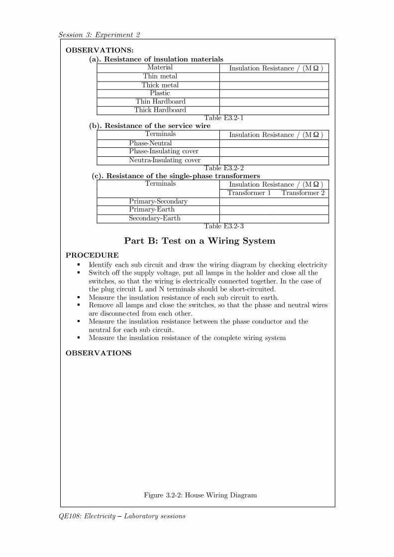
Part B: Test on a Wiring System PROCEDURE § Identify each sub circuit and draw the wiring diagram by checking electricity § Switch off the supply voltage, put all lamps in the holder and close all the
switches, so that the wiring is electrically connected together. In the case of the plug circuit L and N terminals should be short-circuited.
§ Measure the insulation resistance of each sub circuit to earth. § Remove all lamps and close the switches, so that the phase and neutral wires
are disconnected from each other. § Measure the insulation resistance between the phase conductor and the
neutral for each sub circuit. § Measure the insulation resistance of the complete wiring system
OBSERVATIONS
Figure 3.2-2: House Wiring Diagram
Session 3: Experiment 2
QE108: Electricity – Laboratory sessions
Resistance between phase-neutral and phase-earth.
Resistance / (MΩ ) Sub circuit Phase and Earth Phase and Neutral
1 2 3
Table E3.2-4 Insulation resistance of the complete wiring system
§ Phase and earth:........................ § Phase and Neutral: ....................
CALCULATIONS AND RESULTS:
DISCUSSION:
§ Check whether the resistance values that you observed agree with IEE wiring regulations (refer note available)
§ What is the use of having a ring supply § Explain uses of Megger
(a). Calculate the total insulation resistance and leakage current between phase and earth at normal voltage ..........................................................................
..........................................................................
..........................................................................
..........................................................................
..........................................................................
..........................................................................
..........................................................................
..........................................................................
...........................................................
(b). Calculate the total insulation resistance and leakage current between phase and neutral at normal voltage
..................................................................................
..................................................................................
........................................... .......................................
..................................................................................
..................................................................................
........................................... .......................................
.......................................................... ........................
..................................................................................
..................................................................................
Session 4: Experiment 1
QE108: Electricity – Laboratory sessions
Wheatstone Bridge
DATE: OBJECTIVE: § To measure the cold resistance of a tungsten filament lamp
APPARATUS: Identify the following apparatus and note the details
§ Moving coil galvanometer o Identification number: o Full scale deflection with shunt (Ifs):
§ Galvanometer shunt § Decade (Standard) resistance box (R)
o Resistance range: o Resolution: o Voltage rating: o Current rating:
§ Carbon resistors to be used as ratio arms: § DC power supply: (2 V) § Tungsten filament lamp: § Switch
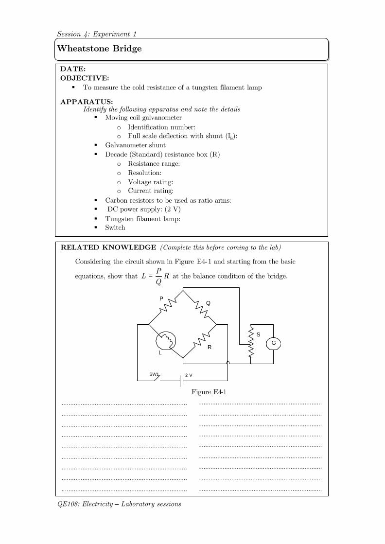
RELATED KNOWLEDGE (Complete this before coming to the lab)
Considering the circuit shown in Figure E4-1 and starting from the basic
equations, show that RQP
L = at the balance condition of the bridge.
PQ
RL
SW1 2 V
SG
Figure E4-1
.......................................................................
................................................... ....................
.......................................................................
.......................................................................
.......................................................................
.......................................................................
.......................................................................
.......................................................................
........................................... ............................
........................................................................
........................................................................
........................................................................
........................................................................
........................................................................
........................................................................
........................................................................
........................................................................
........................................................................
Session 4: Experiment 1
QE108: Electricity – Laboratory sessions
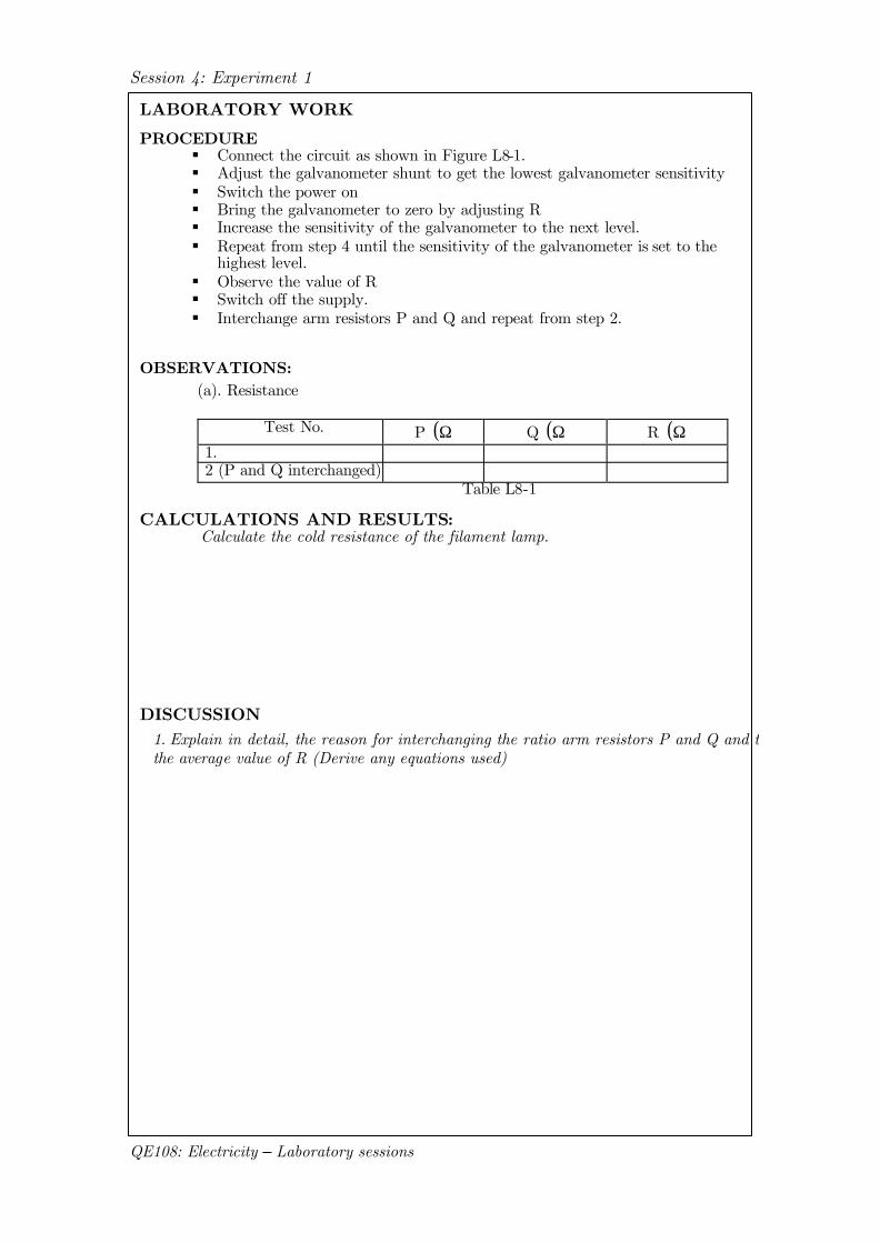
LABORATORY WORK
PROCEDURE § Connect the circuit as shown in Figure L8-1. § Adjust the galvanometer shunt to get the lowest galvanometer sensitivity § Switch the power on § Bring the galvanometer to zero by adjusting R § Increase the sensitivity of the galvanometer to the next level. § Repeat from step 4 until the sensitivity of the galvanometer is set to the
highest level. § Observe the value of R § Switch off the supply. § Interchange arm resistors P and Q and repeat from step 2.
OBSERVATIONS: (a). Resistance
Test No. P ( )Ω Q ( )Ω R ( )Ω
1. 2 (P and Q interchanged)
Table L8-1
CALCULATIONS AND RESULTS: Calculate the cold resistance of the filament lamp.
DISCUSSION
1. Explain in detail, the reason for interchanging the ratio arm resistors P and Q and taking the average value of R (Derive any equations used)