Embed Size (px)
Citation preview
QCN Hardware Evaluation
Abdul Kader Kabbani, Balaji Prabhakar (Stanford University)
Masato Yasuda (NEC)
Overview
• Summary of the Pittsburgh implementation results
• QCN setup in a a real network with – link-level pausing– TCP traffic
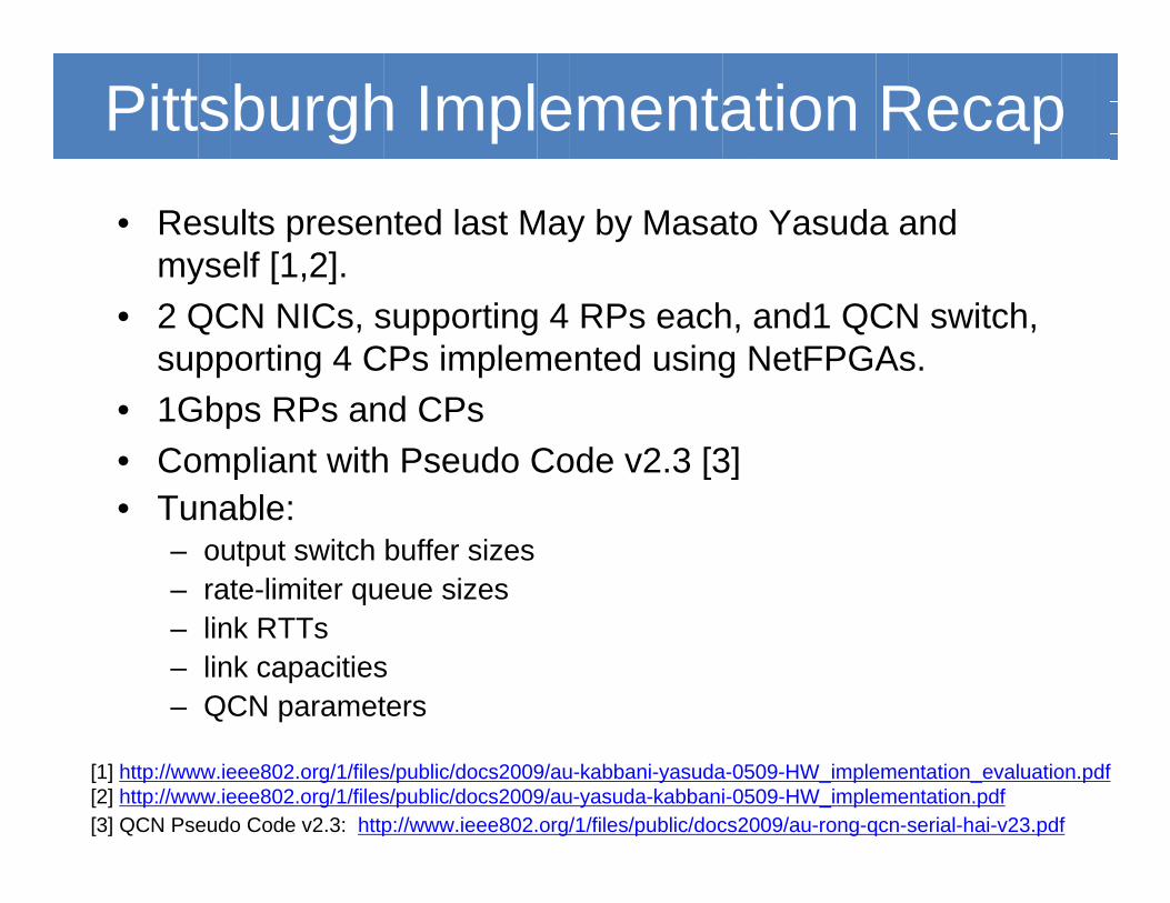
Pittsburgh Implementation Recap• Results presented last May by Masato Yasuda and
myself [1,2].• 2 QCN NICs, supporting 4 RPs each, and1 QCN switch,
supporting 4 CPs implemented using NetFPGAs.• 1Gbps RPs and CPs• Compliant with Pseudo Code v2.3 [3]• Tunable:
– output switch buffer sizes– rate-limiter queue sizes– link RTTs– link capacities– QCN parameters
[3] QCN Pseudo Code v2.3: http://www.ieee802.org/1/files/public/docs2009/au-rong-qcn-serial-hai-v23.pdf
[1] http://www.ieee802.org/1/files/public/docs2009/au-kabbani-yasuda-0509-HW_implementation_evaluation.pdf[2] http://www.ieee802.org/1/files/public/docs2009/au-yasuda-kabbani-0509-HW_implementation.pdf
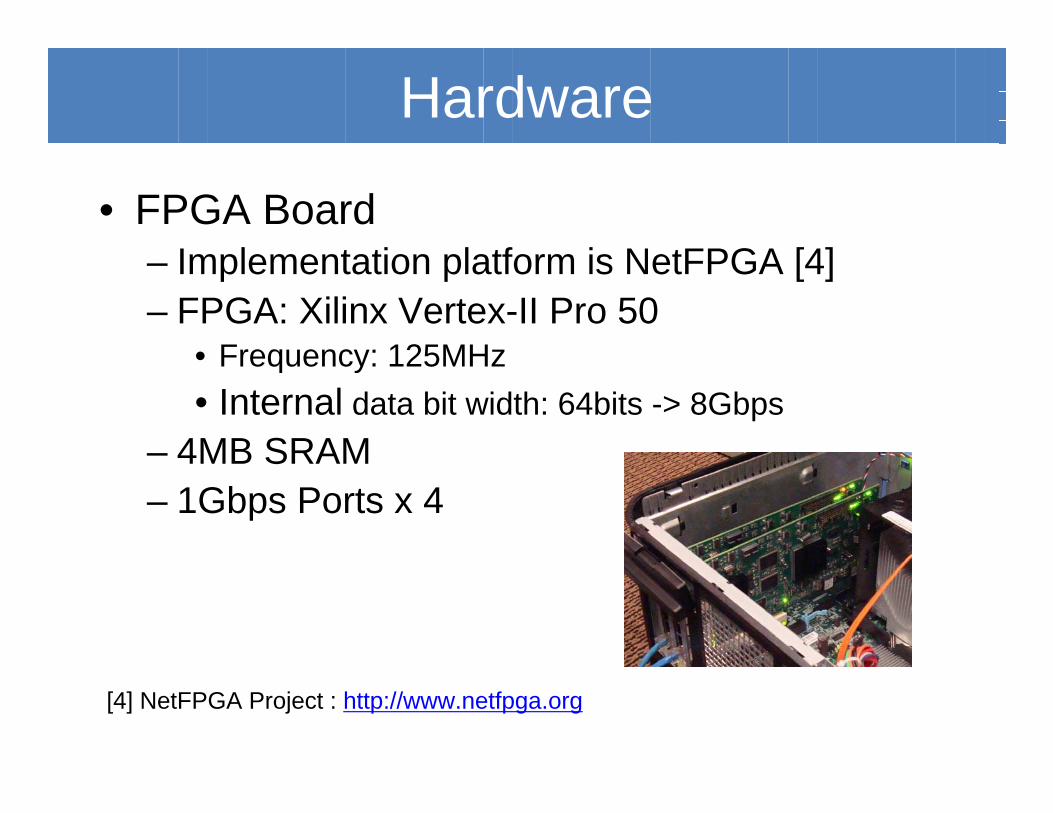
• FPGA Board– Implementation platform is NetFPGA [4]– FPGA: Xilinx Vertex-II Pro 50
• Frequency: 125MHz• Internal data bit width: 64bits -> 8Gbps
– 4MB SRAM– 1Gbps Ports x 4
[4] NetFPGA Project : http://www.netfpga.org
Hardware
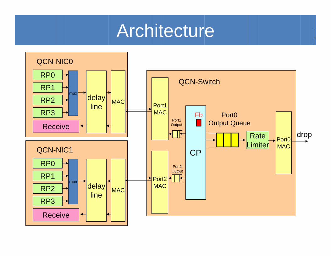
QCN-NIC0
QCN-SwitchRP0
RP1
RP2
RP3
ReceivePort0
Output Queue
CP
RateLimiter
drop
mux
MACdelayline Port1
MAC
Port2MAC
Port0MACQCN-NIC1
RP0
RP1
RP2
RP3
Receive
mux
MACdelayline
FbPort1
Output
Port2Output
Architecture
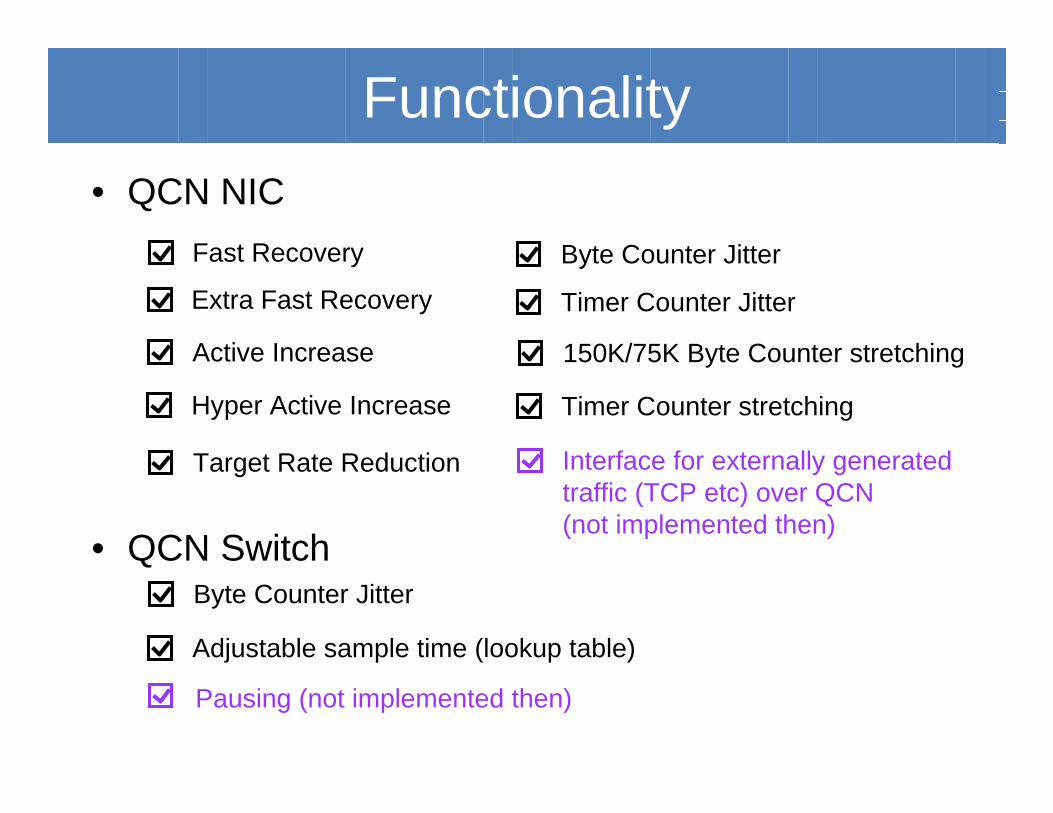
• QCN NIC
• QCN Switch
Fast Recovery
Extra Fast Recovery
Active Increase
Hyper Active Increase
Target Rate Reduction
Byte Counter Jitter
Timer Counter Jitter
150K/75K Byte Counter stretching
Timer Counter stretching
Byte Counter Jitter
Adjustable sample time (lookup table)
Functionality
Pausing (not implemented then)
Interface for externally generatedtraffic (TCP etc) over QCN (not implemented then)
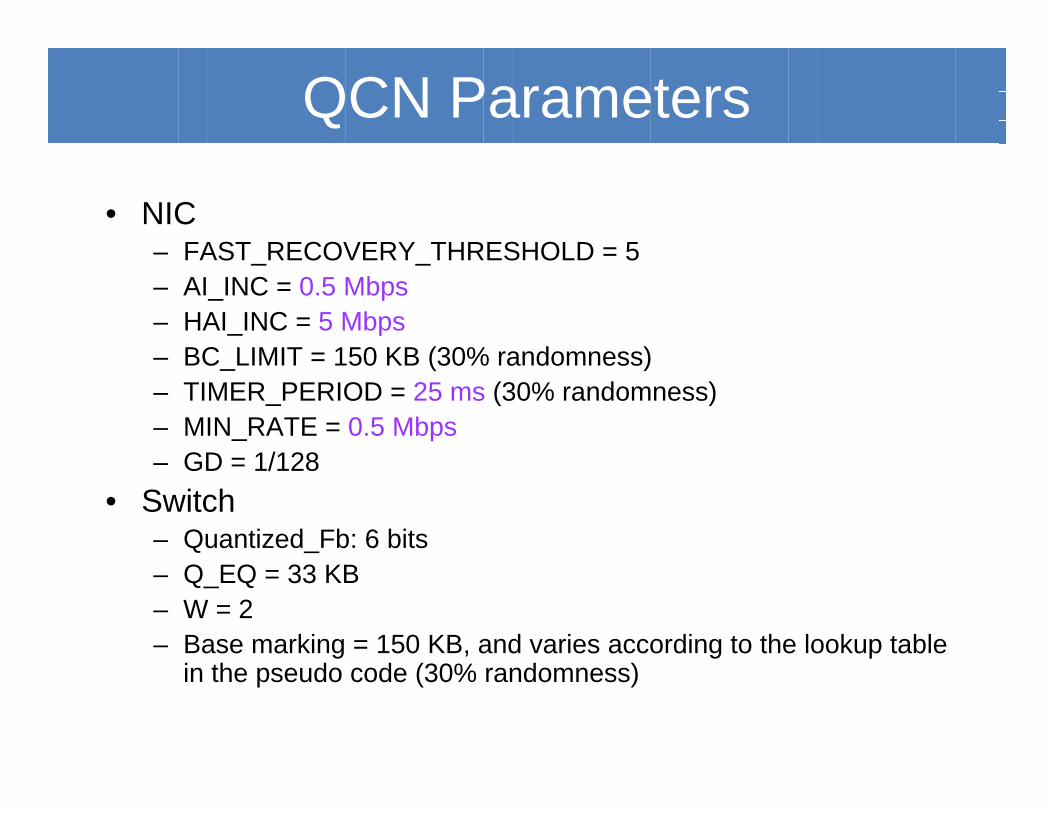
QCN Parameters
• NIC– FAST_RECOVERY_THRESHOLD = 5– AI_INC = 0.5 Mbps– HAI_INC = 5 Mbps– BC_LIMIT = 150 KB (30% randomness)– TIMER_PERIOD = 25 ms (30% randomness)– MIN_RATE = 0.5 Mbps– GD = 1/128
• Switch– Quantized_Fb: 6 bits– Q_EQ = 33 KB– W = 2– Base marking = 150 KB, and varies according to the lookup table
in the pseudo code (30% randomness)
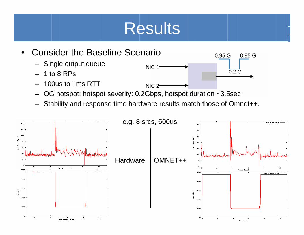
0.95 G0.95 G
0.2 GNIC 1
NIC 2
Results• Consider the Baseline Scenario
– Single output queue– 1 to 8 RPs– 100us to 1ms RTT– OG hotspot; hotspot severity: 0.2Gbps, hotspot duration ~3.5sec– Stability and response time hardware results match those of Omnet++.
Hardware OMNET++
e.g. 8 srcs, 500us
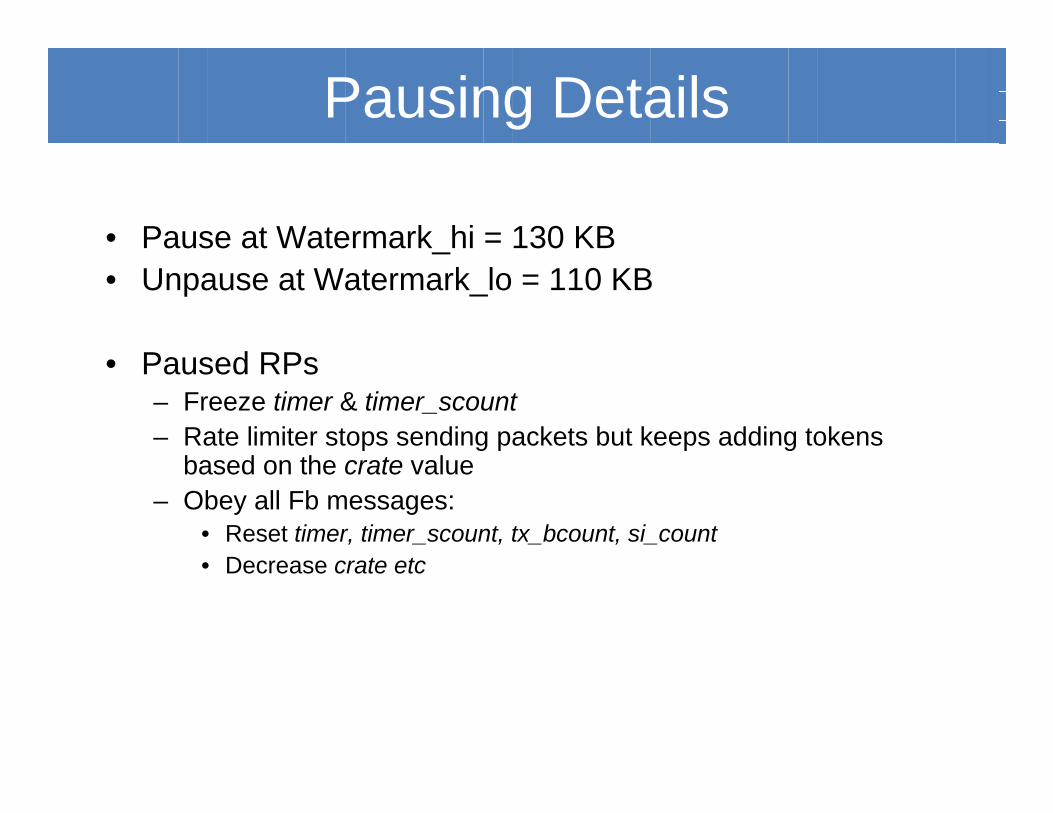
Pausing Details
• Pause at Watermark_hi = 130 KB• Unpause at Watermark_lo = 110 KB
• Paused RPs– Freeze timer & timer_scount– Rate limiter stops sending packets but keeps adding tokens
based on the crate value– Obey all Fb messages:
• Reset timer, timer_scount, tx_bcount, si_count• Decrease crate etc
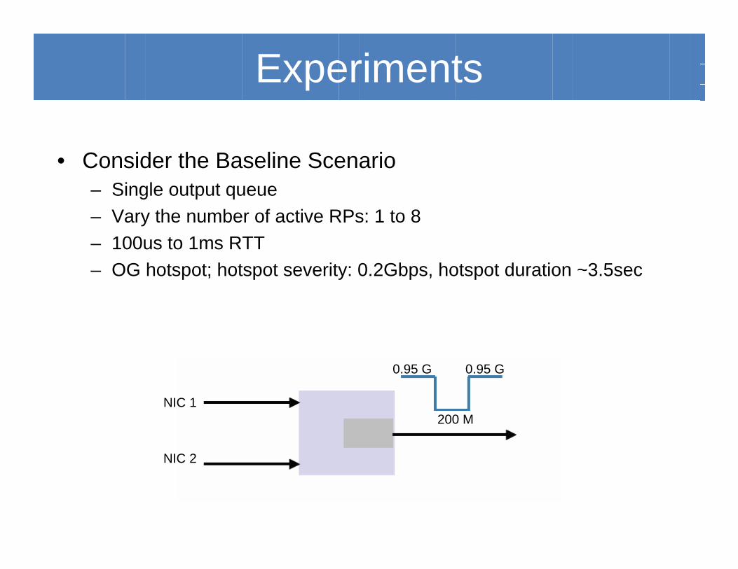
Experiments
• Consider the Baseline Scenario– Single output queue– Vary the number of active RPs: 1 to 8– 100us to 1ms RTT– OG hotspot; hotspot severity: 0.2Gbps, hotspot duration ~3.5sec
0.95 G 0.95 G
200 MNIC 1
NIC 2
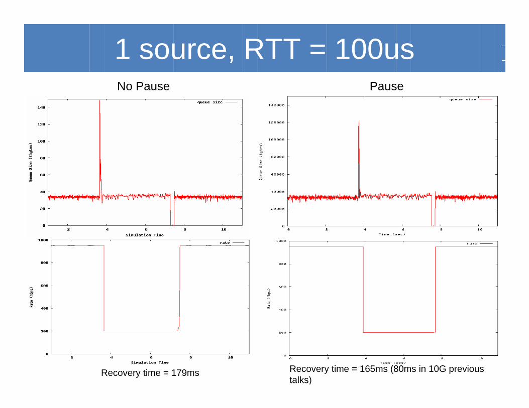
1 source, RTT = 100usNo Pause
Recovery time = 179ms Recovery time = 165ms (80ms in 10G previous talks)
Pause
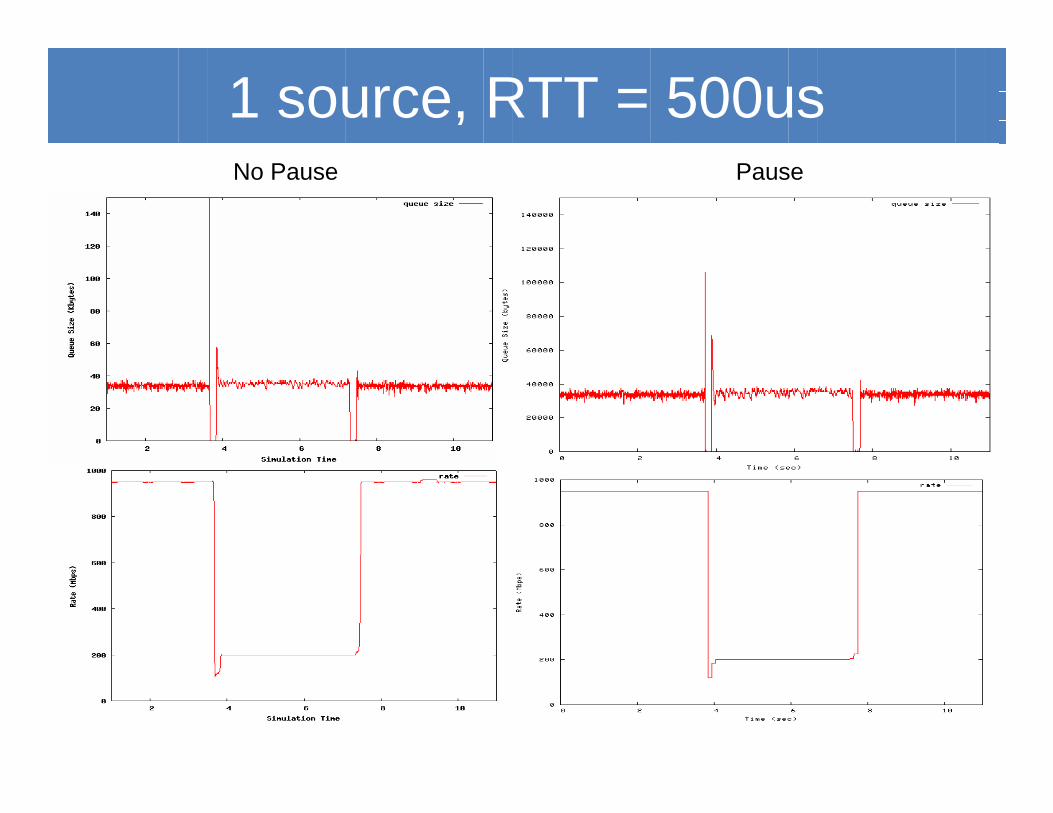
1 source, RTT = 500usNo Pause Pause
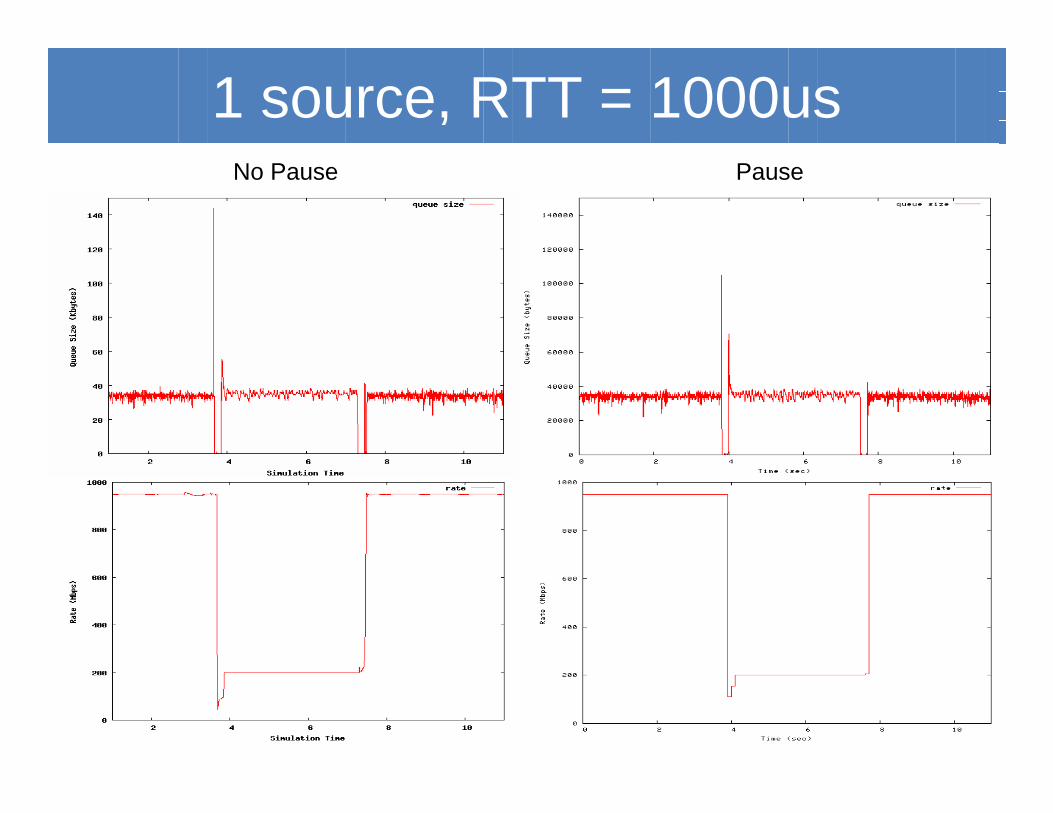
1 source, RTT = 1000usNo Pause Pause
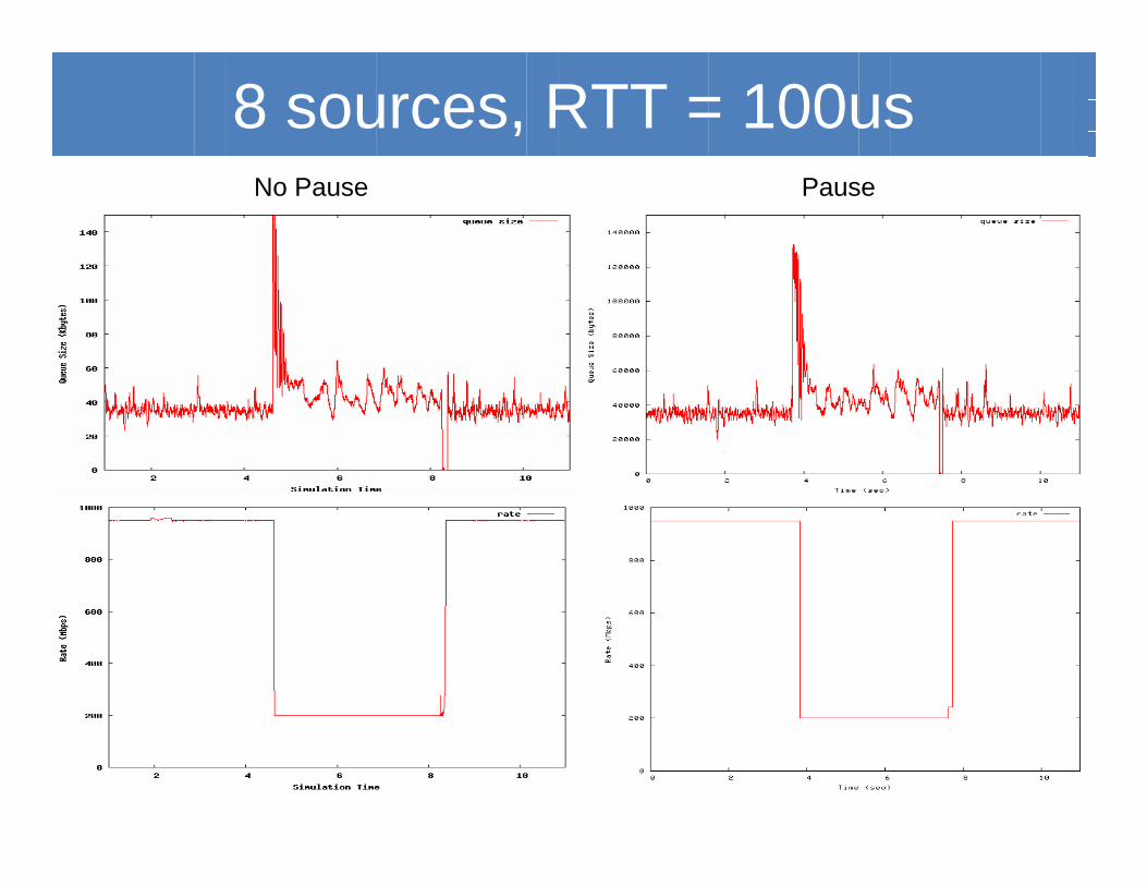
8 sources, RTT = 100usNo Pause Pause
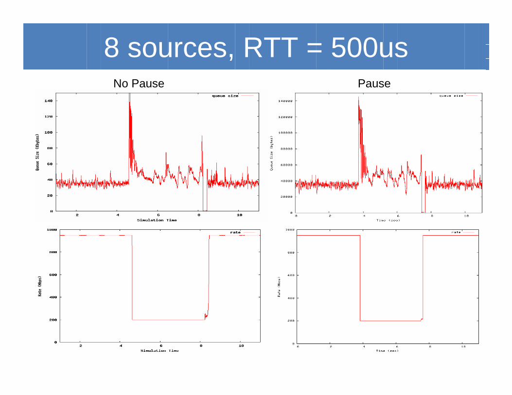
8 sources, RTT = 500usNo Pause Pause
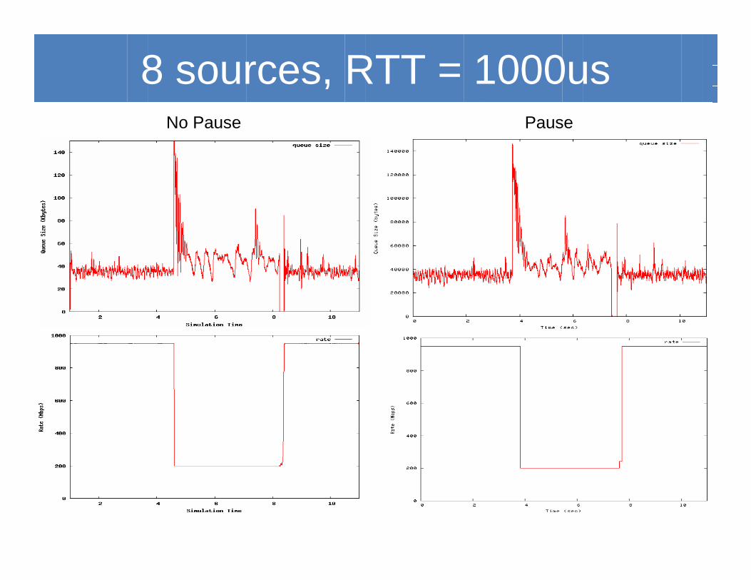
8 sources, RTT = 1000usNo Pause Pause

TCP & QCN
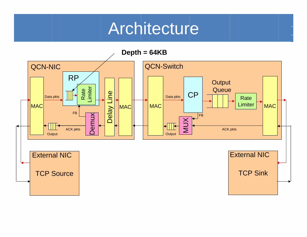
QCN-NIC QCN-Switch
Output Queue
CP RateLimiterMAC
Del
ay L
ine
MAC MAC
Output
Architecture
Rat
eLi
mite
rD
emux
RP
MU
X
FB FB
OutputACK pktsACK pkts
Data pktsData pkts
TCP Source
External NIC External NIC
MAC
TCP Sink
External NIC
Depth = 64KB
• Maximum achievable TCP rate ~800Mbps due to the PCI bandwidth limitation
• Link speed = 750Mbps • 1 TCP-capable RP per NIC• Next we observe the queue length and TCP’s
throughput (BIC & New-Reno):– with and without qcn– as we vary the RTT from 200us to 400us
Parameters
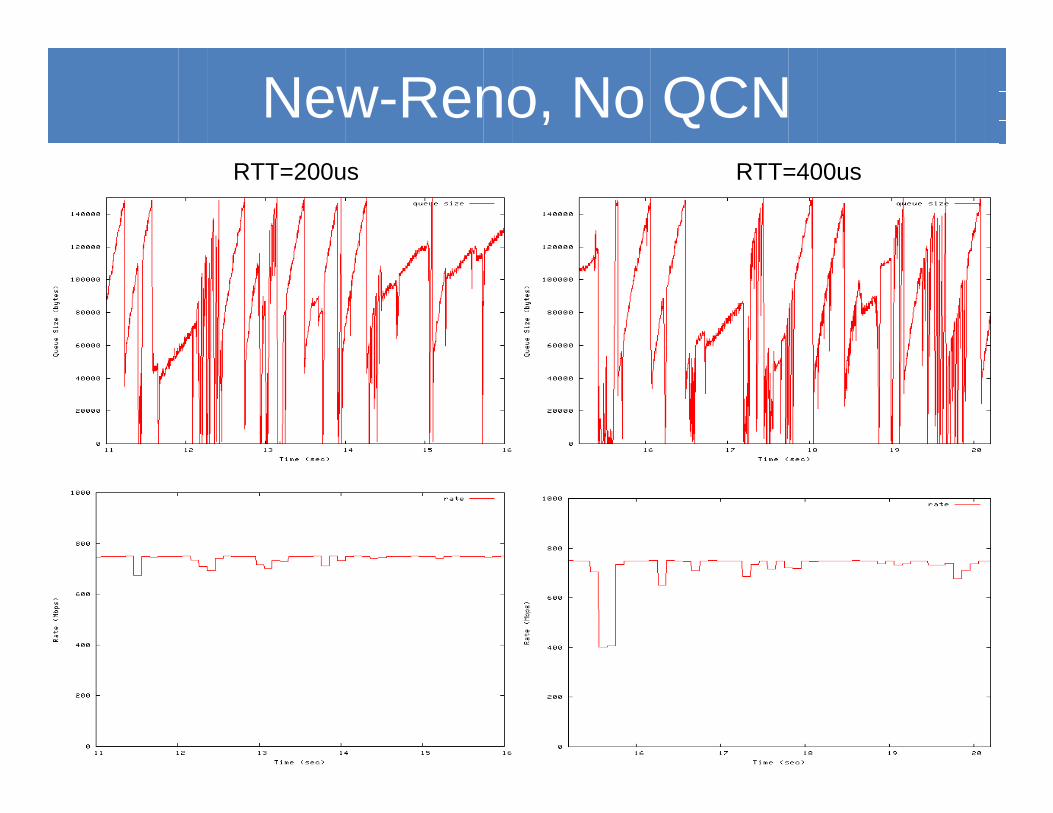
New-Reno, No QCNRTT=200us RTT=400us
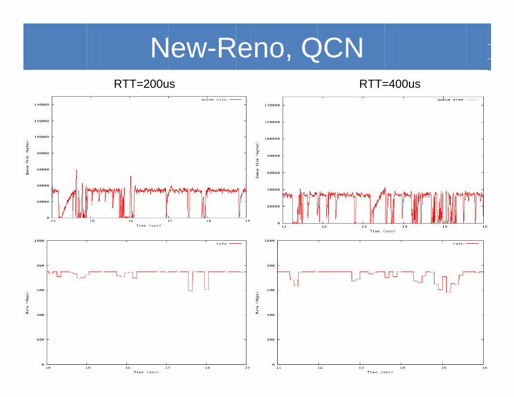
New-Reno, QCNRTT=200us RTT=400us
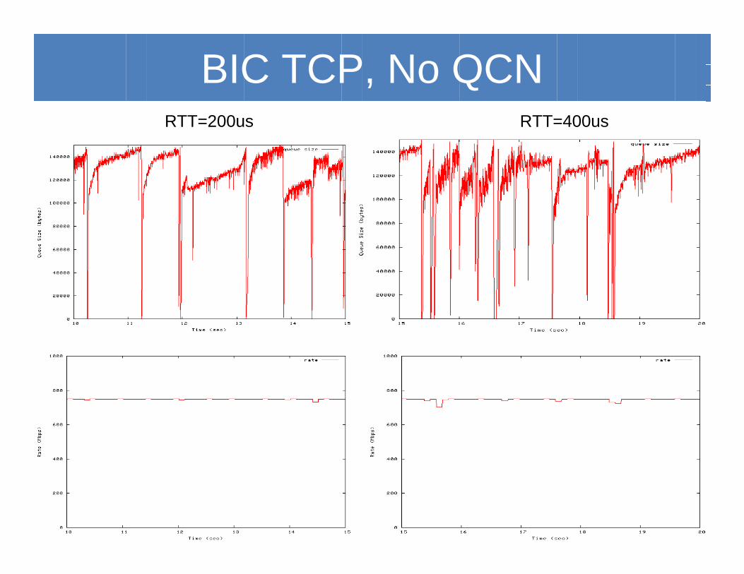
BIC TCP, No QCNRTT=200us RTT=400us
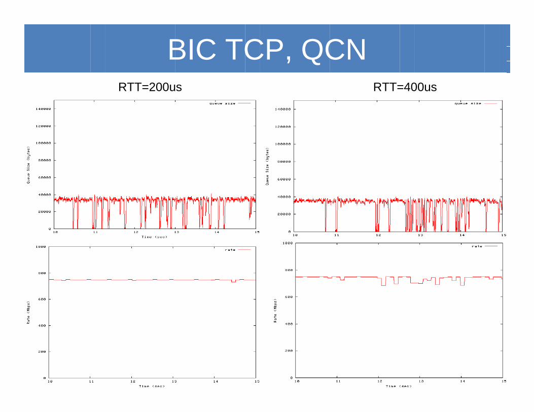
BIC TCP, QCNRTT=200us RTT=400us
Summary
• Demonstrated successful QCN system operation• Experiments and simulations match very well• Built a test-bed for conducting further experiments
– Scalable topologies for data centers (4 RPs and 4 CPs per FPGA board)
– Tunable:• output switch buffer sizes• rate-limiter queue sizes• link RTTs• link capacities• QCN parameters
– Ability to trace and analyze all major QCN variables• Easily portable to 10Gbps hardware