Embed Size (px)
Citation preview
8/13/2019 QCA Material
http://slidepdf.com/reader/full/qca-material 1/5
Quantum cellular automata:
Introduction:
For the past 30 years, microelectronics industries have succeeded in making huge leaps
in increasing the speed and reducing the power requirements of electronic devices. According
to Moore’s law, number of devices integrated in a chip doubles every 18-24 months.
International Technology Roadmap for Semiconductors (ITRS) reported that this trend is
expected to continue until 2020. Beyond that the physical and power density restrictions would
restrict further scaling of integrated circuits in modern-day manufacturing technology of CMOS.
In order to further increase device density, microelectronics industries have to change from the
established prototype to a new prototype which can get over these effects i.e. Quantum-dot
Cellular Automata (QCA)
QCA-Cell, a basic device, enables high device densities and also can function at THz
frequencies by consuming low power. QCA cell contains electrons that help in encoding binary
information.
The position of electrons is decided by Columbic interaction between electrons and this
facilitates signal transmission and thus the logic state of a cell.
It depends on the Columbic interaction between device cells. A QCA cell consists of four
charge containers or “dots”, placed at the corners of a square.
QCA Cell
QCA cell enables both computation and transmission of information
QCA cell consists of four Quantum-dots in a square array & two electrons.
The quantum dots are coupled through potential barriers and the electrons can tunnel
through the barriers depending on their heights.
The potential barrier heights are controlled by external voltage.
If the potential barriers are low the electrons can easily tunnel through them. If they are
raised, the electrons cannot tunnel and the cell is latched.
The cell has two minimum state arrangements.
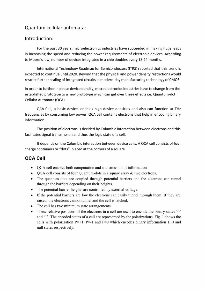
These relative positions of the electrons in a cell are used to encode the binary states ‘0’
and ‘1’. The encoded states of a cell are represented by the polarizations. Fig. 1 shows the
cells with polarization P=+1, P=-1 and P=0 which encodes binary information 1, 0 and
null states respectively.
8/13/2019 QCA Material
http://slidepdf.com/reader/full/qca-material 2/5
Polarisation of a qca cell is influenced by using an 1) external electric potential or 2) by the
neighboring cells.
How do you achieve correct room temperature operation of QCA
individual cells?
1) The gap between energy levels in a single quantum-dot must be greater than the thermal
noise.
2) The difference between the two lower energy states and the third higher energy state in a
QCA cell must be greater than the thermal noise.
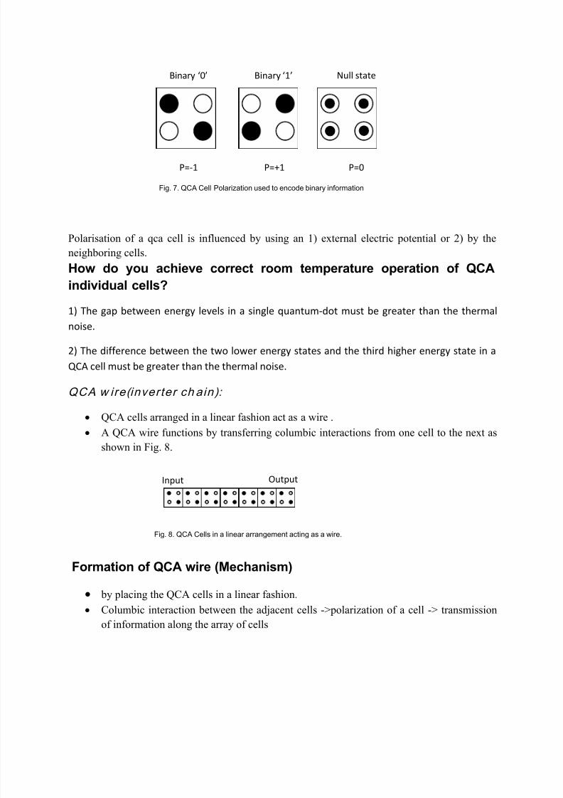
QCA w ire(inverter ch ain):
QCA cells arranged in a linear fashion act as a wire . A QCA wire functions by transferring columbic interactions from one cell to the next as
shown in Fig. 8.
Formation of QCA wire (Mechanism)
by placing the QCA cells in a linear fashion.
Columbic interaction between the adjacent cells ->polarization of a cell -> transmission
of information along the array of cells
Fig. 8. QCA Cells in a linear arrangement acting as a wire.
Input Output
Fig. 7. QCA Cell Polarization used to encode binary information
P=-1 P=+1 P=0
Binary ‘0’ Binary ‘1’ Null state
8/13/2019 QCA Material
http://slidepdf.com/reader/full/qca-material 3/5
The input cell is strongly polarized in one direction. Thus it acts as a driver to the other
cells in the NULL state.
QCA inv erter
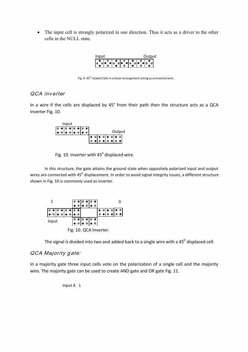
In a wire if the cells are displaced by 45° from their path then the structure acts as a QCA
inverter Fig. 10.
In this structure, the gate attains the ground state when oppositely polarized input and output
wires are connected with 45O displacement. In order to avoid signal integrity issues, a different structure
shown in Fig. 10 is commonly used as inverter.
The signal is divided into two and added back to a single wire with a 45O displaced cell.
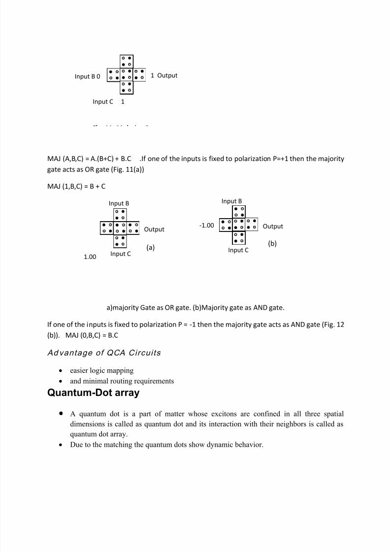
QCA Major i ty g ate:
In a majority gate three input cells vote on the polarization of a single cell and the majority
wins. The majority gate can be used to create AND gate and OR gate Fig. 11.
Fig. 10. QCA Inverter.
Input
01
Fig. 10. Inverter with 45o displaced wire.
Input
Output
Fig. 9. 45O rotated Cells in a linear arrangement acting as aninverted wire.
Input Output
Input A 1
8/13/2019 QCA Material
http://slidepdf.com/reader/full/qca-material 4/5
8/13/2019 QCA Material
http://slidepdf.com/reader/full/qca-material 5/5
Example
Metallic islands of gold clusters
Arrangement is via self organization
Dimension of single island is in nanometer
Appl icat ion:
Quantum computer.
Solving nonlinear differential equations in QCA network.
Associative information storage system.
Image processing.
![0 0-------. I:0 0-------. .-------0lent/pdf/nd/ElectronicQCA.pdf · clocked QCA cells, a QCA shift register, and power gain in QCA cells [14, IS]. At an early stage of QCA development](https://img.pdfslide.us/doc/110x75/6145851207bb162e665fbe8b/0-0-i0-0-0-lentpdfnd-clocked-qca-cells-a-qca-shift.jpg)