Embed Size (px)
Citation preview
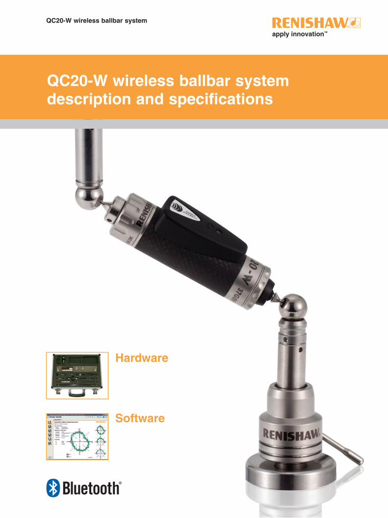
QC20-W wireless ballbar system
QC20-W wireless ballbar system description and specifications
Hardware
Software
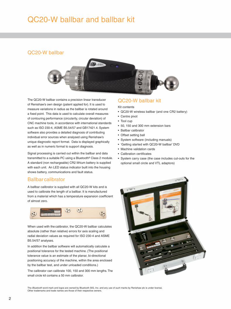
QC20-W ballbar and ballbar kit
The QC20-W ballbar contains a precision linear transducer
of Renishaw’s own design (patent applied for). It is used to
measure variations in radius as the ballbar is rotated around
a fixed point. This data is used to calculate overall measures
of contouring performance (circularity, circular deviation) of
CNC machine tools, in accordance with international standards
such as ISO 230-4, ASME B5.54/57 and GB17421.4. System
software also provides a detailed diagnosis of contributing
individual error sources when analysed using Renishaw’s
unique diagnostic report format. Data is displayed graphically
as well as in numeric format to support diagnosis.
Signal processing is carried out within the ballbar and data
transmitted to a suitable PC using a Bluetooth® Class 2 module.
A standard (non rechargeable) CR2 lithium battery is supplied
with each unit. An LED status indicator built into the housing
shows battery, communications and fault status.
Ballbar calibratorA ballbar calibrator is supplied with all QC20-W kits and is
used to calibrate the length of a ballbar. It is manufactured
from a material which has a temperature expansion coefficient
of almost zero.
When used with the calibrator, the QC20-W ballbar calculates
absolute (rather than relative) errors for axis scaling and
radial deviation values as required for ISO 230-4 and ASME
B5.54/57 analyses.
In addition the ballbar software will automatically calculate a
positional tolerance for the tested machine. (The positional
tolerance value is an estimate of the planar, bi-directional
positioning accuracy of the machine, within the area enclosed
by the ballbar test, and under unloaded conditions.)
The calibrator can calibrate 100, 150 and 300 mm lengths. The
small circle kit contains a 50 mm calibrator.
QC20-W ballbar kitKit contents
• QC20-W wireless ballbar (and one CR2 battery)
• Centre pivot
• Tool cup
• 50, 150 and 300 mm extension bars
• Ballbar calibrator
• Offset setting ball
• System software (including manuals)
• ‘Getting started with QC20-W ballbar’ DVD
• Machine validation cards
• Calibration certificates
• System carry case (the case includes cut-outs for the
optional small circle and VTL adaptors)
2
QC20-W ballbar
The Bluetooth word mark and logos are owned by Bluetooth SIG, Inc. and any use of such marks by Renishaw plc is under license. Other trademarks and trade names are those of their respective owners.
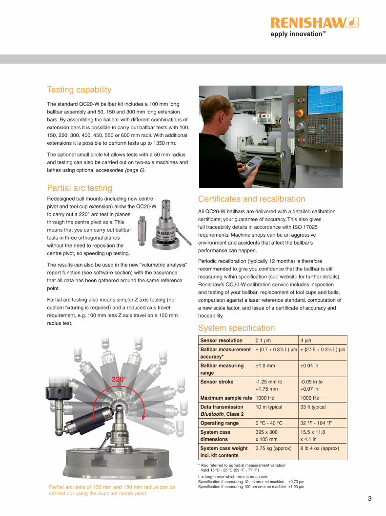
220°
3
Testing capability
The standard QC20-W ballbar kit includes a 100 mm long
ballbar assembly and 50, 150 and 300 mm long extension
bars. By assembling the ballbar with different combinations of
extension bars it is possible to carry out ballbar tests with 100,
150, 250, 300, 400, 450, 550 or 600 mm radii. With additional
extensions it is possible to perform tests up to 1350 mm.
The optional small circle kit allows tests with a 50 mm radius
and testing can also be carried out on two-axis machines and
lathes using optional accessories (page 6).
Partial arc testingRedesigned ball mounts (including new centre
pivot and tool cup extension) allow the QC20-W
to carry out a 220° arc test in planes
through the centre pivot axis. This
means that you can carry out ballbar
tests in three orthogonal planes
without the need to reposition the
centre pivot, so speeding up testing.
The results can also be used in the new “volumetric analysis”
report function (see software section) with the assurance
that all data has been gathered around the same reference
point.
Partial arc testing also means simpler Z axis testing (no
custom fixturing is required) and a reduced axis travel
requirement, e.g. 100 mm less Z axis travel on a 150 mm
radius test.
Certificates and recalibration All QC20-W ballbars are delivered with a detailed calibration
certificate; your guarantee of accuracy. This also gives
full traceability details in accordance with ISO 17025
requirements. Machine shops can be an aggressive
environment and accidents that affect the ballbar’s
performance can happen.
Periodic recalibration (typically 12 months) is therefore
recommended to give you confidence that the ballbar is still
measuring within specification (see website for further details).
Renishaw’s QC20-W calibration service includes inspection
and testing of your ballbar, replacement of tool cups and balls,
comparison against a laser reference standard, computation of
a new scale factor, and issue of a certificate of accuracy and
traceability.
System specification
Partial arc tests of 100 mm and 150 mm radius can be carried out using the supplied centre pivot.
* Also referred to as ‘radial measurement variation’ Valid 15 °C - 25 °C (59 °F - 77 °F)
L = length over which error is measured Specification if measuring 10 µm error on machine ±0.73 µm Specification if measuring 100 µm error on machine ±1.00 µm
Sensor resolution 0.1 µm 4 µin
Ballbar measurement ± (0.7 + 0.3% L) µm ± (27.6 + 0.3% L) µin accuracy*
Ballbar measuring ±1.0 mm ±0.04 in range
Sensor stroke -1.25 mm to -0.05 in to +1.75 mm +0.07 in
Maximum sample rate 1000 Hz 1000 Hz
Data transmission 10 m typical 33 ft typical Bluetooth, Class 2
Operating range 0 °C - 40 °C 32 °F - 104 °F
System case 395 x 300 15.5 x 11.8 dimensions x 105 mm x 4.1 in
System case weight 3.75 kg (approx) 8 lb 4 oz (approx) incl. kit contents
Ballbar plot simulator
This is a powerful tool to aid decisions on corrective action
or maintenance prediction. The simulator allows users to
see their test results on screen and then to change various
machine geometry, play and dynamic parameters to see
“what if” results on the ballbar plot, circularity and positional
tolerance values. The original test results are maintained
separately and cannot be corrupted, no matter what
scenarios are played out in the simulator.
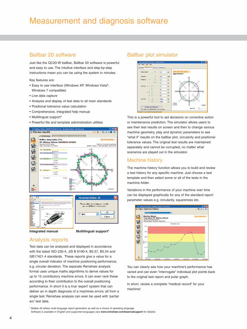
Machine history
The machine history function allows you to build and review
a test history for any specific machine. Just choose a test
template and then select some or all of the tests in the
machine folder.
Variations in the performance of your machine over time
can be displayed graphically for any of the standard report
parameter values e.g. circularity, squareness etc.
You can clearly see how your machine’s performance has
varied and can even “interrogate” individual plot points back
to the original test report and polar graph.
In short, review a complete “medical record” for your
machine!
* Ballbar 20 allows multi-language report generation as well as a choice of operating language. Software is available in English and supported languages (see www.renishaw.com/lasercalsupport for details)
Measurement and diagnosis software
4
Integrated manual Multilingual support*
Ballbar 20 softwareJust like the QC20-W ballbar, Ballbar 20 software is powerful
and easy to use. The intuitive interface and step-by-step
instructions mean you can be using the system in minutes.
Key features are:
• Easy to use interface (Windows XP, Windows Vista®,
Windows 7 compatible)
• Live data capture
• Analysis and display of test data to all main standards
• Positional tolerance value calculation
• Comprehensive, integrated help manual
• Multilingual support*
• Powerful file and template administration utilities
Analysis reportsTest data can be analysed and displayed in accordance
with the latest ISO 230-4, JIS B 6190-4, B5.57, B5.54 and
GB17421.4 standards. These reports give a value for a
single overall indicator of machine positioning performance,
e.g. circular deviation. The separate Renishaw analysis
format uses unique maths algorithms to derive values for
up to 15 contributory machine errors. It can even rank these
according to their contribution to the overall positioning
performance. In short it is a true ‘expert’ system that can
deliver an in depth diagnosis of a machines errors; all from a
single test. Renishaw analysis can even be used with ‘partial
arc’ test data.
The software also allows you to:
• Set individual warning and failure performance bands for
each machine characteristic
• Get instant notification, during the ballbar test, if a
machine’s performance exceeds these tolerances
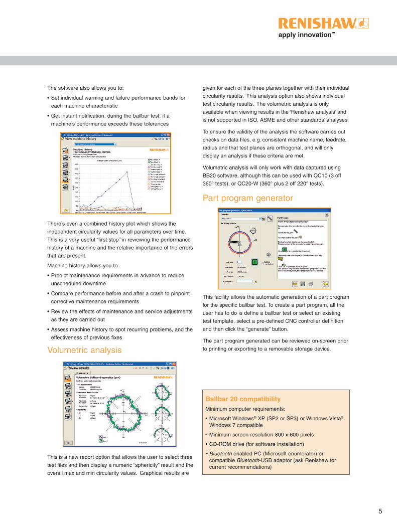
There’s even a combined history plot which shows the
independent circularity values for all parameters over time.
This is a very useful “first stop” in reviewing the performance
history of a machine and the relative importance of the errors
that are present.
Machine history allows you to:
• Predict maintenance requirements in advance to reduce
unscheduled downtime
• Compare performance before and after a crash to pinpoint
corrective maintenance requirements
• Review the effects of maintenance and service adjustments
as they are carried out
• Assess machine history to spot recurring problems, and the
effectiveness of previous fixes
Volumetric analysis
This is a new report option that allows the user to select three
test files and then display a numeric “sphericity” result and the
overall max and min circularity values. Graphical results are
given for each of the three planes together with their individual
circularity results. This analysis option also shows individual
test circularity results. The volumetric analysis is only
available when viewing results in the ‘Renishaw analysis’ and
is not supported in ISO, ASME and other standards’ analyses.
To ensure the validity of the analysis the software carries out
checks on data files, e.g. consistent machine name, feedrate,
radius and that test planes are orthogonal, and will only
display an analysis if these criteria are met.
Volumetric analysis will only work with data captured using
BB20 software, although this can be used with QC10 (3 off
360° tests), or QC20-W (360° plus 2 off 220° tests).
Part program generator
This facility allows the automatic generation of a part program
for the specific ballbar test. To create a part program, all the
user has to do is define a ballbar test or select an existing
test template, select a pre-defined CNC controller definition
and then click the “generate” button.
The part program generated can be reviewed on-screen prior
to printing or exporting to a removable storage device.
Ballbar 20 compatibilityMinimum computer requirements:
• Microsoft Windows® XP (SP2 or SP3) or Windows Vista®, Windows 7 compatible
• Minimum screen resolution 800 x 600 pixels
• CD-ROM drive (for software installation)
• Bluetooth enabled PC (Microsoft enumerator) or compatible Bluetooth-USB adaptor (ask Renishaw for current recommendations)
5
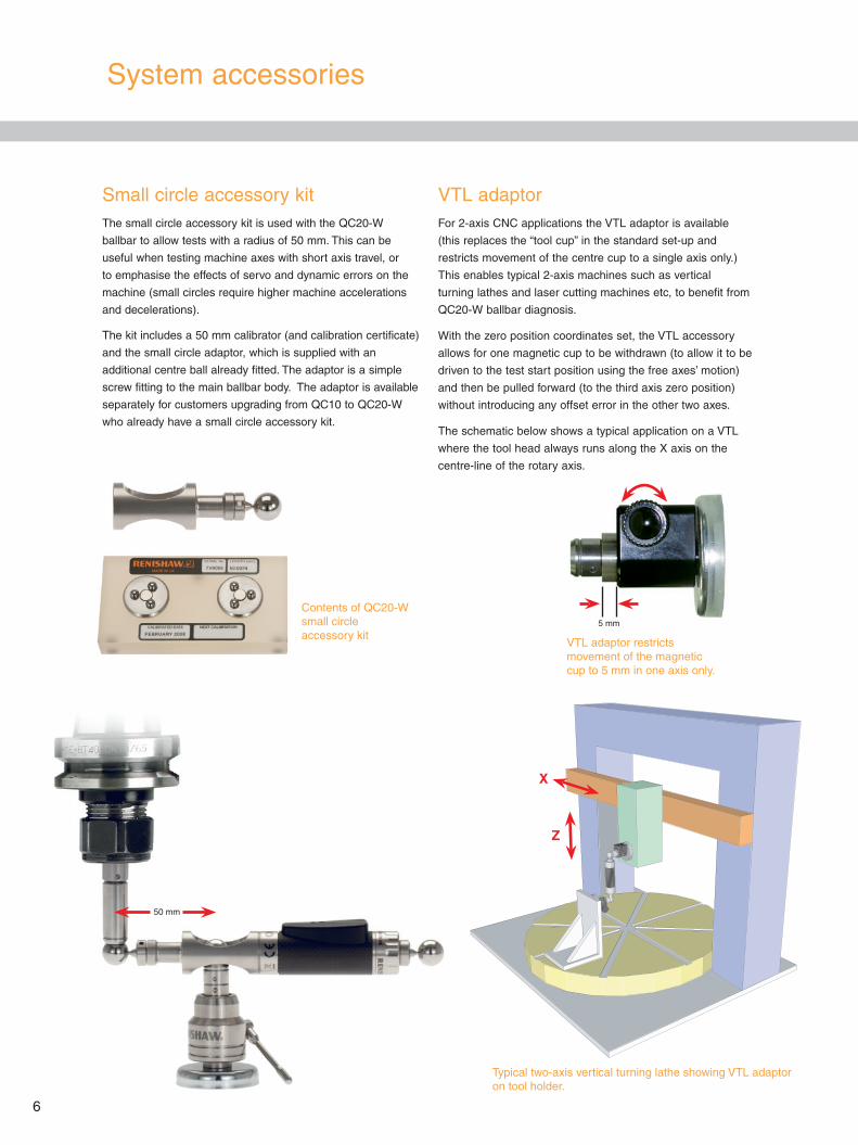
Small circle accessory kitThe small circle accessory kit is used with the QC20-W
ballbar to allow tests with a radius of 50 mm. This can be
useful when testing machine axes with short axis travel, or
to emphasise the effects of servo and dynamic errors on the
machine (small circles require higher machine accelerations
and decelerations).
The kit includes a 50 mm calibrator (and calibration certificate)
and the small circle adaptor, which is supplied with an
additional centre ball already fitted. The adaptor is a simple
screw fitting to the main ballbar body. The adaptor is available
separately for customers upgrading from QC10 to QC20-W
who already have a small circle accessory kit.
VTL adaptorFor 2-axis CNC applications the VTL adaptor is available
(this replaces the “tool cup” in the standard set-up and
restricts movement of the centre cup to a single axis only.)
This enables typical 2-axis machines such as vertical
turning lathes and laser cutting machines etc, to benefit from
QC20-W ballbar diagnosis.
With the zero position coordinates set, the VTL accessory
allows for one magnetic cup to be withdrawn (to allow it to be
driven to the test start position using the free axes’ motion)
and then be pulled forward (to the third axis zero position)
without introducing any offset error in the other two axes.
The schematic below shows a typical application on a VTL
where the tool head always runs along the X axis on the
centre-line of the rotary axis.
6
System accessories
VTL adaptor restricts movement of the magnetic cup to 5 mm in one axis only.
5 mm
50 mm
Typical two-axis vertical turning lathe showing VTL adaptor on tool holder.
Z
X
Contents of QC20-W small circle accessory kit
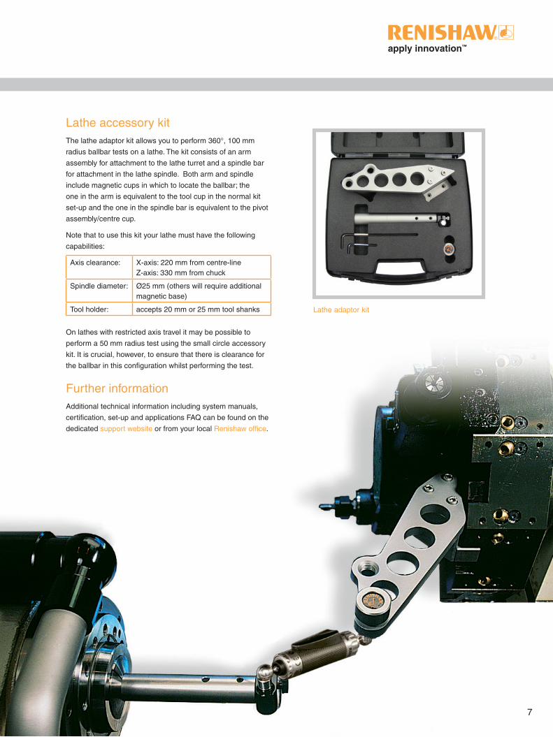
Lathe accessory kitThe lathe adaptor kit allows you to perform 360°, 100 mm
radius ballbar tests on a lathe. The kit consists of an arm
assembly for attachment to the lathe turret and a spindle bar
for attachment in the lathe spindle. Both arm and spindle
include magnetic cups in which to locate the ballbar; the
one in the arm is equivalent to the tool cup in the normal kit
set-up and the one in the spindle bar is equivalent to the pivot
assembly/centre cup.
Note that to use this kit your lathe must have the following
capabilities:
Axis clearance: X-axis: 220 mm from centre-lineZ-axis: 330 mm from chuck
Spindle diameter: Ø25 mm (others will require additional magnetic base)
Tool holder: accepts 20 mm or 25 mm tool shanks
On lathes with restricted axis travel it may be possible to
perform a 50 mm radius test using the small circle accessory
kit. It is crucial, however, to ensure that there is clearance for
the ballbar in this configuration whilst performing the test.
Further informationAdditional technical information including system manuals,
certification, set-up and applications FAQ can be found on the
dedicated support website or from your local Renishaw office.
Lathe adaptor kit
7

*L-8014-1588-07-A*
Renishaw plc
New Mills, Wotton-under-Edge, Gloucestershire GL12 8JR United Kingdom
T +44 (0) 1453 524524 F +44 (0) 1453 524901 E [email protected]
www.renishaw.com
Issued: 0413 Part no. L-8014-1588-07-A
© 2010-2013 Renishaw plc. All rights reserved. Renishaw reserves the right to change specifications without noticeRENISHAW and the probe symbol used in the RENISHAW logo are registered trade marks of Renishaw plc in the United Kingdom and other countries. apply innovation and names and designations of other Renishaw products and technologies are trade marks of Renishaw plc or its subsidiaries. All other brand names and product names used in this document are trade names, trade marks or registered trade marks of their respective owners.
RENISHAW HAS MADE CONSIDERABLE EFFORTS TO ENSURE THE CONTENT OF THIS DOCUMENT IS CORRECT AT THE DATE OF PUBLICATION BUT MAKES NO WARRANTIES OR REPRESENTATIONS REGARDING THE CONTENT. RENISHAW EXCLUDES LIABILITY, HOWSOEVER ARISING, FOR ANY INACCURACIES IN THIS DOCUMENT.
For worldwide contact details, please visit our main website at www.renishaw.com/contact
About Renishaw
Renishaw is an established world leader in engineering technologies, with a strong history of innovation in product development and manufacturing. Since its formation in 1973, the company has supplied leading-edge products that increase process productivity, improve product quality and deliver cost-effective automation solutions.
A worldwide network of subsidiary companies and distributors provides exceptional service and support for its customers.
Products include:• Additive manufacturing, vacuum casting, and injection moulding technologies for design, prototyping, and production applications
• Advanced material technologies with a variety of applications in multiple fields
• Dental CAD/CAM scanning and milling systems and supply of dental structures
• Encoder systems for high accuracy linear, angle and rotary position feedback
• Fixturing for CMMs (co-ordinate measuring machines) and gauging systems
• Gauging systems for comparative measurement of machined parts
• High speed laser measurement and surveying systems for use in extreme environments
• Laser and ballbar systems for performance measurement and calibration of machines
• Medical devices for neurosurgical applications
• Probe systems and software for job set-up, tool setting and inspection on CNC machine tools
• Raman spectroscopy systems for non-destructive material analysis
• Sensor systems and software for measurement on CMMs
• Styli for CMM and machine tool probe applications