Embed Size (px)
Citation preview
Document for the developers and community users
Qblinks Qmote Maker’s Module Developer Guide This document is for Qmote Developers and Community Revision Information V0.1/2015-‐APR-‐16
Init Draft V1.1/2015-‐JUNE-‐18 Reduced output message length V1.2/2015-‐JULY-‐2 Added status of HID CCC V1.3/2015-‐JULY-‐15 Added status of Bonding Keys Full V1.4/2015-‐AUGUST-‐6 Added AT+BF command V1.5/2015-‐AUGUST-‐27 Added button combination code list V1.6/2015-‐AUGUST-‐31 Added antenna wire on drawing to indicate the module orientation
Document for the developers and community users
Introduction Qmote Maker’s Module is the world’s first Bluetooth Low Energy Module that allows you connect your DIY development board and kit to all of the major Smart Home products in the market, as well as most social network platforms without doing any coding. Qmote Maker’s Module is functionally the same as the standard Qmote with additional extensions designed for makers. It can send commands to control your Smartphone. It is also compatible with IFTTT, so you can make your development board work with the hundreds of other channels. It is easy to use Qmote Maker’s Module. You don’t need to have any App or Cloud programming skills. Simply send commands from your development boards through UART to Qmote Maker’s Module.
Specifications Main Chipset TI CC2541F256 Protocol Standard Bluetooth V4.0 Low Energy Transmit Output Power -‐6 ≤ Output Power ≤ +4; Class 2 Device Receiver Sensitivity < 0.1% BER at -‐70 dBm Operating Voltage 3.3V ± 0.3V Power Consumption TX: 14mA; RX: 14mA
Document for the developers and community users
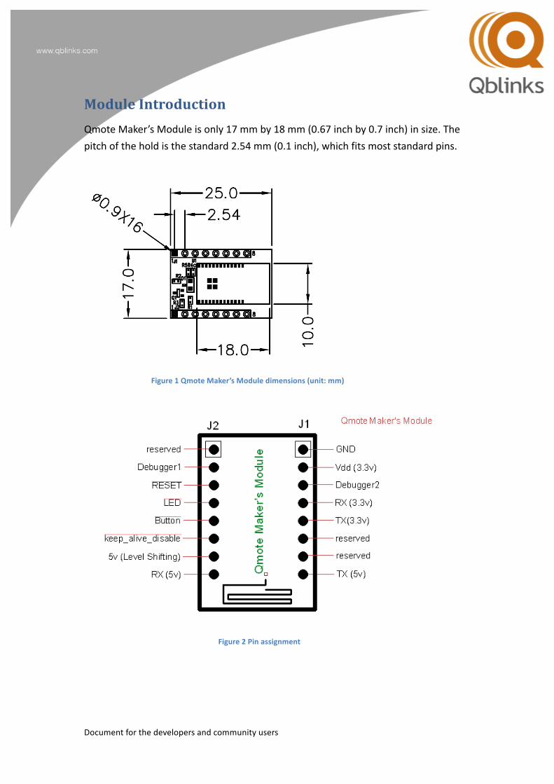
Module Introduction Qmote Maker’s Module is only 17 mm by 18 mm (0.67 inch by 0.7 inch) in size. The pitch of the hold is the standard 2.54 mm (0.1 inch), which fits most standard pins.
Figure 1 Qmote Maker’s Module dimensions (unit: mm)
Figure 2 Pin assignment
Document for the developers and community users
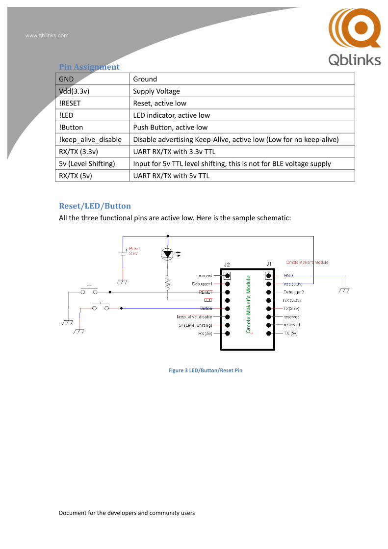
Pin Assignment GND Ground Vdd(3.3v) Supply Voltage !RESET Reset, active low !LED LED indicator, active low !Button Push Button, active low !keep_alive_disable Disable advertising Keep-‐Alive, active low (Low for no keep-‐alive) RX/TX (3.3v) UART RX/TX with 3.3v TTL 5v (Level Shifting) Input for 5v TTL level shifting, this is not for BLE voltage supply RX/TX (5v) UART RX/TX with 5v TTL
Reset/LED/Button All the three functional pins are active low. Here is the sample schematic:
Figure 3 LED/Button/Reset Pin
Document for the developers and community users
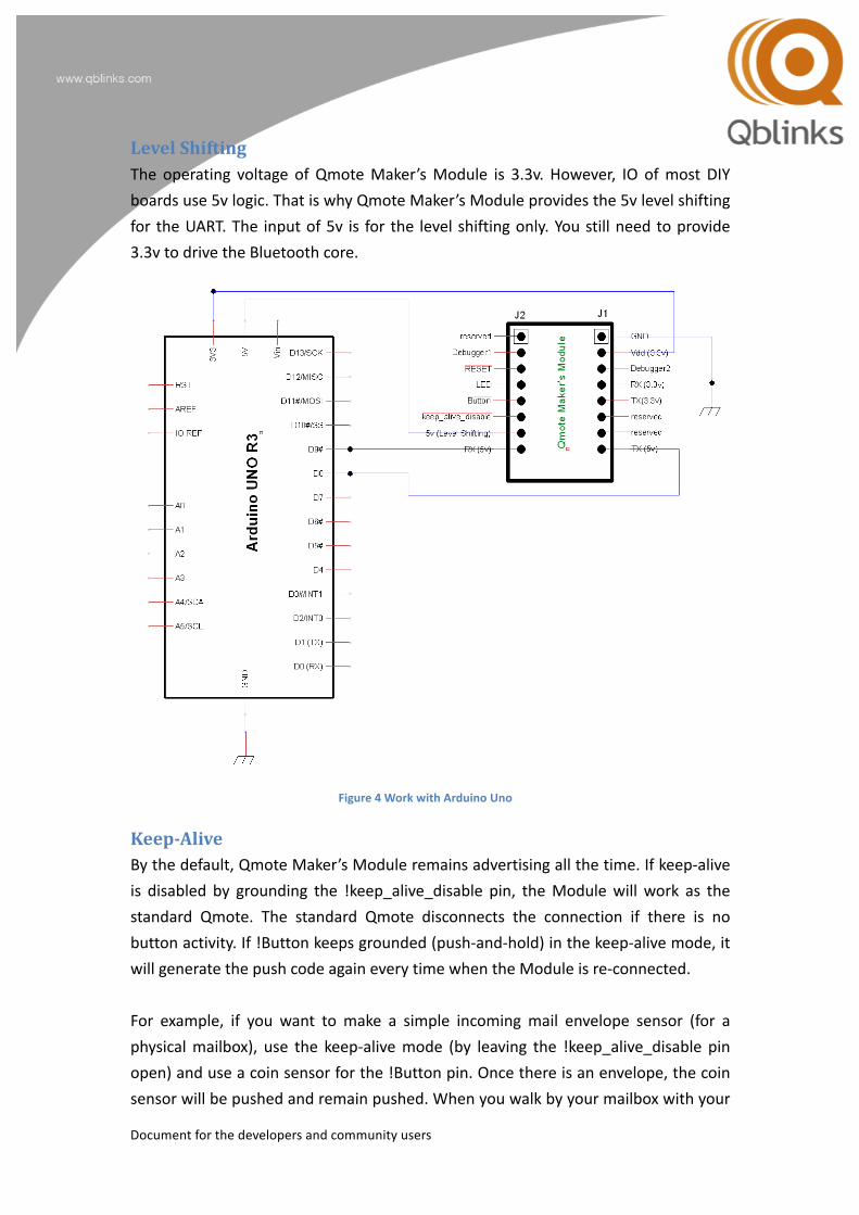
Level Shifting The operating voltage of Qmote Maker’s Module is 3.3v. However, IO of most DIY boards use 5v logic. That is why Qmote Maker’s Module provides the 5v level shifting for the UART. The input of 5v is for the level shifting only. You still need to provide 3.3v to drive the Bluetooth core.
Figure 4 Work with Arduino Uno
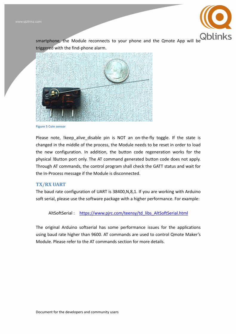
Keep-‐‑Alive By the default, Qmote Maker’s Module remains advertising all the time. If keep-‐alive is disabled by grounding the !keep_alive_disable pin, the Module will work as the standard Qmote. The standard Qmote disconnects the connection if there is no button activity. If !Button keeps grounded (push-‐and-‐hold) in the keep-‐alive mode, it will generate the push code again every time when the Module is re-‐connected. For example, if you want to make a simple incoming mail envelope sensor (for a physical mailbox), use the keep-‐alive mode (by leaving the !keep_alive_disable pin open) and use a coin sensor for the !Button pin. Once there is an envelope, the coin sensor will be pushed and remain pushed. When you walk by your mailbox with your
Document for the developers and community users
smartphone, the Module reconnects to your phone and the Qmote App will be triggered with the find-‐phone alarm.
Figure 5 Coin sensor
Please note, !keep_alive_disable pin is NOT an on-‐the-‐fly toggle. If the state is changed in the middle of the process, the Module needs to be reset in order to load the new configuration. In addition, the button code regeneration works for the physical !Button port only. The AT command generated button code does not apply. Through AT commands, the control program shall check the GATT status and wait for the In-‐Process message if the Module is disconnected.
TX/RX UART The baud rate configuration of UART is 38400,N,8,1. If you are working with Arduino soft serial, please use the software package with a higher performance. For example:
AltSoftSerial : https://www.pjrc.com/teensy/td_libs_AltSoftSerial.html The original Arduino softserial has some performance issues for the applications using baud rate higher than 9600. AT commands are used to control Qmote Maker’s Module. Please refer to the AT commands section for more details.
Document for the developers and community users
AT Commands AT commands comprises of three parts. “AT”, followed by a command, and a termination character <cr>, which means Carriage-‐Return. The command will be processed after the <cr> is sent. The response from each command varies. In general, a successful command will respond with OK. For example, if you send AT<cr>, you will get <cr><lf>OK<cr><lf>. AT<cr> <cr><lf> OK<cr><lf> Note: <cr> is ASCII 0x0D, <lf> is ASCII 0x0A. <lf> from input will be ignored.
AT commands summary Command Descriptions Possible Response ATI0 Get the device information INFO: <device info> ATI1 Get the firmware version number INFO: FW <ver> ATI2 Get system clock INFO: CLOCK <clock> ATE0 Local UART echo off OK ATE1 Local UART echo on (default) OK ATZ0 Force Commit (NVRAM) OK ATZ1 Reset configuration (of current
connected device) OK
ATZ3 Software Reset OK ATZ5 Reset and Enter OAD mode OK ATZ7 Total Factory Reset. This erase
everything from Qmote configurations to all Bluetooth exchanged bonding keys.
device will be reset
ATX0 Force non-‐presenter mode OK ATX1 Force presenter-‐mode OK ATL1=n Start LED blinking for 60 seconds, where
n 0: Just once 1: Slow
OK
Document for the developers and community users
2: Medium 3: Fast 5: Non-‐Stop
ATL0 Stop LED blinking OK ATL2=n Set button response time, where n is
one byte hex number 0x80~0xFF slow 0x00 normal 0x01~0x7F faster This uses 2’s compliment 0x80-‐-‐-‐-‐-‐0x00-‐-‐-‐-‐-‐0x7F
OK or Err if value is incorrect
ATBN=n Send button combination code n, where n is in the hex format. E.g. ATBN=0x01 Remember to send release code by ATB0 afterward. Otherwise, it will be considered as button on-‐hold. Note: Button on-‐hold through AT command will NOT trigger on-‐hold phone finder. Use ATBN=0xFF for the find phone alert, instead.
OK or Err if combination code is invalid
ATBN=0x0C Recall virtual keyboard. This works for iOS only. Remember to send release code by ATB0 afterward.
OK
ATBN=0xFF This triggers the Find Phone alert. Remember to send release code by ATB0 afterward to stop the alert.
OK
ATBN=n,<msg> Send button combination code with IFTTT message. The length of the message cannot exceed 19 bytes. Once <msg> is used, ATB0 will be sent automatically. In another word, this command cannot be used as the finder trigger. <msg> can be either “ASCII message” or 0xhex value. E.g. ATBN=0x01,”TEXT” or ATBN=0x01,0x1122
OK or Err if the combination code is invalid or the message is too long
ATB0 Send button release code. This is OK
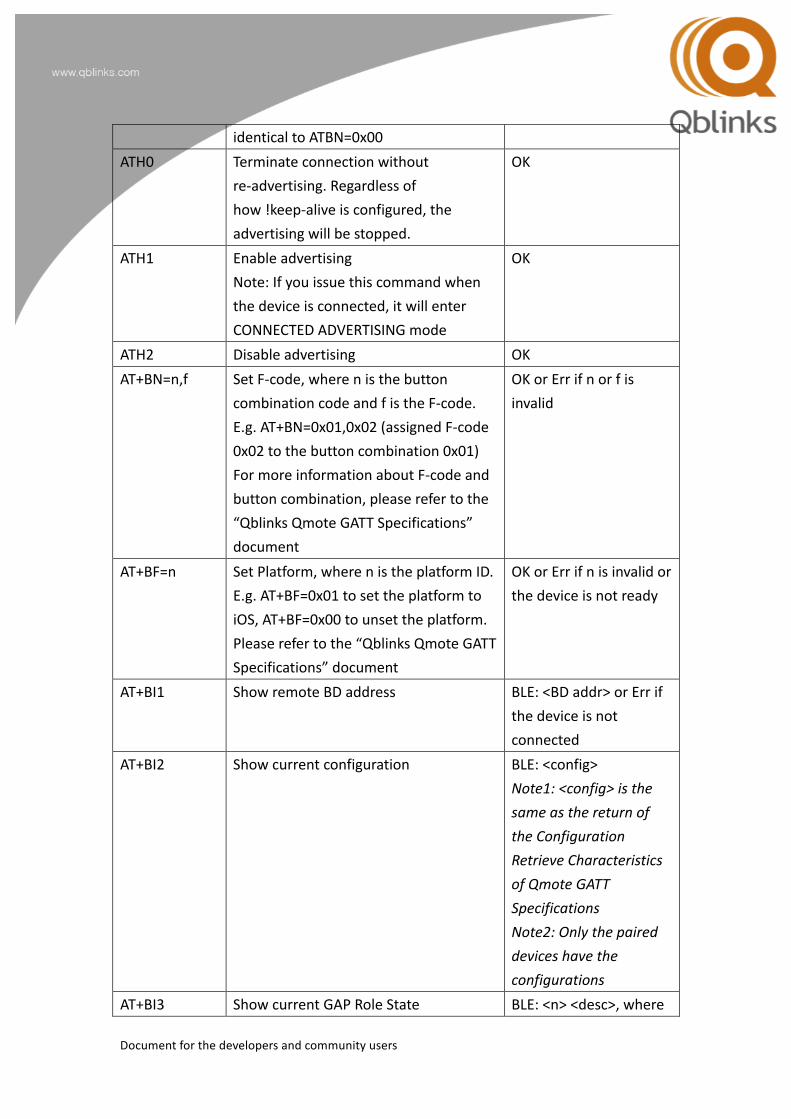
Document for the developers and community users
identical to ATBN=0x00 ATH0 Terminate connection without
re-‐advertising. Regardless of how !keep-‐alive is configured, the advertising will be stopped.
OK
ATH1 Enable advertising Note: If you issue this command when the device is connected, it will enter CONNECTED ADVERTISING mode
OK
ATH2 Disable advertising OK AT+BN=n,f Set F-‐code, where n is the button
combination code and f is the F-‐code. E.g. AT+BN=0x01,0x02 (assigned F-‐code 0x02 to the button combination 0x01) For more information about F-‐code and button combination, please refer to the “Qblinks Qmote GATT Specifications” document
OK or Err if n or f is invalid
AT+BF=n Set Platform, where n is the platform ID. E.g. AT+BF=0x01 to set the platform to iOS, AT+BF=0x00 to unset the platform. Please refer to the “Qblinks Qmote GATT Specifications” document
OK or Err if n is invalid or the device is not ready
AT+BI1 Show remote BD address BLE: <BD addr> or Err if the device is not connected
AT+BI2 Show current configuration BLE: <config> Note1: <config> is the same as the return of the Configuration Retrieve Characteristics of Qmote GATT Specifications Note2: Only the paired devices have the configurations
AT+BI3 Show current GAP Role State BLE: <n> <desc>, where
Document for the developers and community users
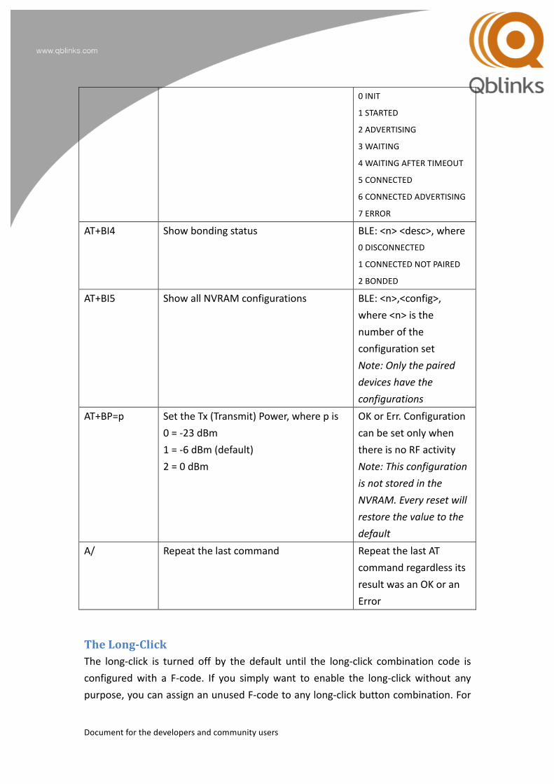
0 INIT
1 STARTED
2 ADVERTISING
3 WAITING
4 WAITING AFTER TIMEOUT
5 CONNECTED
6 CONNECTED ADVERTISING
7 ERROR AT+BI4 Show bonding status BLE: <n> <desc>, where
0 DISCONNECTED
1 CONNECTED NOT PAIRED
2 BONDED AT+BI5 Show all NVRAM configurations BLE: <n>,<config>,
where <n> is the number of the configuration set Note: Only the paired devices have the configurations
AT+BP=p Set the Tx (Transmit) Power, where p is 0 = -‐23 dBm 1 = -‐6 dBm (default) 2 = 0 dBm
OK or Err. Configuration can be set only when there is no RF activity Note: This configuration is not stored in the NVRAM. Every reset will restore the value to the default
A/ Repeat the last command Repeat the last AT command regardless its result was an OK or an Error
The Long-‐‑Click The long-‐click is turned off by the default until the long-‐click combination code is configured with a F-‐code. If you simply want to enable the long-‐click without any purpose, you can assign an unused F-‐code to any long-‐click button combination. For

Document for the developers and community users
example, ATBN=0x05,0x99, to assigns F-‐code, 0x99, which is not functional, to the button combination code, 0x05, which is long-‐short.
Document for the developers and community users
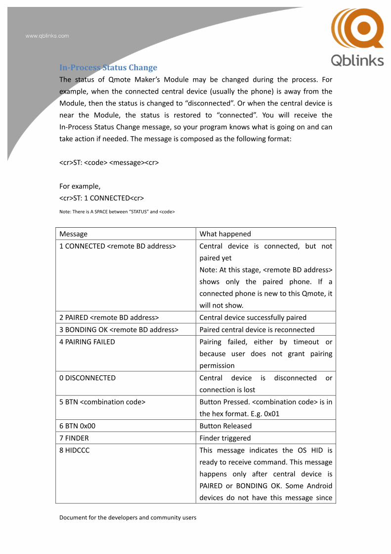
In-‐‑Process Status Change The status of Qmote Maker’s Module may be changed during the process. For example, when the connected central device (usually the phone) is away from the Module, then the status is changed to “disconnected”. Or when the central device is near the Module, the status is restored to “connected”. You will receive the In-‐Process Status Change message, so your program knows what is going on and can take action if needed. The message is composed as the following format: <cr>ST: <code> <message><cr> For example, <cr>ST: 1 CONNECTED<cr>
Note: There is A SPACE between “STATUS” and <code>
Message What happened 1 CONNECTED <remote BD address> Central device is connected, but not
paired yet Note: At this stage, <remote BD address> shows only the paired phone. If a connected phone is new to this Qmote, it will not show.
2 PAIRED <remote BD address> Central device successfully paired 3 BONDING OK <remote BD address> Paired central device is reconnected 4 PAIRING FAILED Pairing failed, either by timeout or
because user does not grant pairing permission
0 DISCONNECTED Central device is disconnected or connection is lost
5 BTN <combination code> Button Pressed. <combination code> is in the hex format. E.g. 0x01
6 BTN 0x00 Button Released 7 FINDER Finder triggered 8 HIDCCC This message indicates the OS HID is
ready to receive command. This message happens only after central device is PAIRED or BONDING OK. Some Android devices do not have this message since
Document for the developers and community users
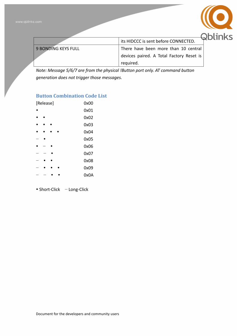
its HIDCCC is sent before CONNECTED. 9 BONDING KEYS FULL There have been more than 10 central
devices paired. A Total Factory Reset is required.
Note: Message 5/6/7 are from the physical !Button port only. AT command button generation does not trigger those messages.
Button Combination Code List [Release] 0x00 � 0x01 � � 0x02 � � � 0x03 � � � � 0x04 − � 0x05 � − � 0x06 − − � 0x07 − � � 0x08 − � � � 0x09 − − � � 0x0A
� Short-‐Click − Long-‐Click