Embed Size (px)
Citation preview
MINISTRY OF SCIENCE AND TECHNOLOGY
DEPARTMENT OF TECHNICAL AND VOCATIONAL EDUCATION
Sample Questions & Worked Out Examples for
CE-05016 DESIGN OF HYDRAULIC STRUCTURES
B.E.
Civil Engineering
MINISTRY OF SCIENCE AND TECHNOLOGY
DEPARTMENT OF
TECHNICAL AND VOCATIONAL EDUCATION
CE-05016
DESIGN OF HYDRAULIC STRUCTURES
Sample Questions
B.E.
Civil Engineering

Note
* Must Know
** Should Know
*** Could Know
CE 05016 Design of Hydraulic Structures
Sample Questions
Chapter 1. Spillway
1.* What are the essential requirements of a spillway? How would you select a
suitable site for the spillway?
2.* What are the factors that affect the spillway capacity? How would you fix the
spillway capacity?
3.* Describe the various component part of the spillway. Explain their functions.
4.* How would you classify the spillway. Explain their functions.
5.* How would you classify the spillway based on the purpose and based on the
control? Explain in detail.
6.* Discuss the working and uses of free overfall spillway. Why this type of
spillway is not common?
7.* Explain the design of an ogee-shaped spillway. How would you fix the d/s and
u/s profiles?
8.* How would you compute the discharge over an ogee-shaped spillway?
Discuss the various factors which affect the coefficient of discharge.
9.* What is a spillway? What are its functions? Discuss in brief the various types
of spillways.
10.* Write short notes on: (a) chute spillway (b) side channel spillway.
11.* Write short notes on siphon spillways.
12.* Write short notes on: (a) tunnel spillway (b) cascade spillway.
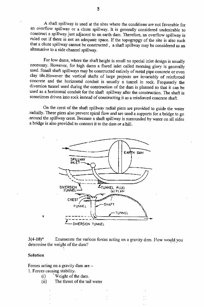
13.* Write short note on morning glory spillway.
14.* Write short note on spillway gates. Describe different type of spillway gates?
15.** An overflow spillway with u/s face vertical is to be designed for a flood of
2100 cumecs. The level of the spillway crest is at R.L of 130.00 and the river
bed is at R.L of 100.00. The end walls of the spillway are 79m apart, and
there are 4 round nosed piers, each 1 m wide. Determine the total head over
the crest. Take C = 2.20 and Ka = 0.10. Also draw the spillway profile.
16.** The crest level of an ogee-shaped spillway is at RL of 323.00 m and the
maximum reservoir level is 334.00m. Calculate the maximum discharge when
the flow takes place through 5 piers of the effective width of 12 m each. Take
C = 2.20
17.*** In order to dissipate the energy below spillway, it is proposed to form a
hydraulic jump. If the depth of flow changes from 1.0 m to 4.0 m in the
hydraulic jump, determine the initial Froude number and the discharge
intensity.
18.*** The crest of an ogee – shaped spillway is at a height of 10 m above the river
bed. If the head over the crest is 3m, find the loss of energy when a hydraulic
jump forms at the toe. Take C = 2.20.
Chapter 2. Stilling Basin
1.* Discuss the characteristics of a hydraulic jump. Differentiate between the tail
water rating curve (TWRC) and the jump height curve (JHC). How would you
select the most suitable type of energy dissipating device for the different
relative positions of the two curves?
2.* What are the different types of energy dissipating methods used below the
spillway?
3.* What are the different types of I. S stilling basins for the horizontal aprons?
Compare these with U.S.B.R stilling basins.
4.* Discuss various bucket-type energy dissipaters. Where would you provide
each type?
5.** Design a suitable stilling basin at the toe of a spillway from the following
data:
Discharge intensity = 24.6 cumecs/ m
H.F.L in the reservoir = 100.0 m
Spillway crest level = 95.0 m
River bed level = 59.0 m
Tail water level = 69.0 m
Coefficient of velocity = 0.90
Assume Lb/y2 = 4.30
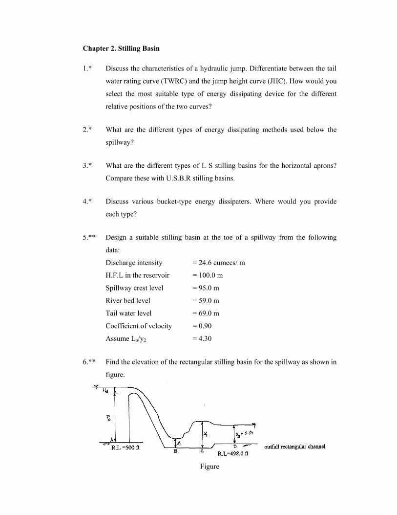
6.** Find the elevation of the rectangular stilling basin for the spillway as shown in
figure.
Figure
Give data:
Design discharge Q = 1600 cusec.
Base width of the stilling basin L = 40 ft.
Design head Hd = 5 ft.., P0 = 20 ft.
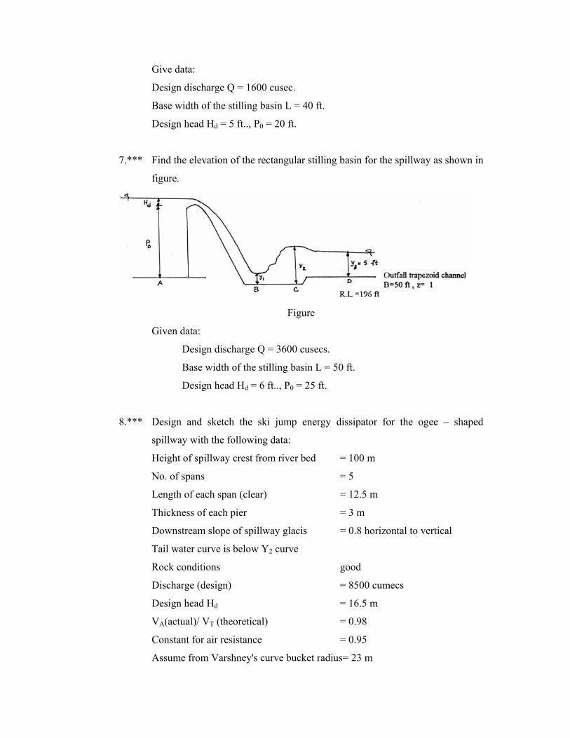
7.*** Find the elevation of the rectangular stilling basin for the spillway as shown in
figure.
Figure
Given data:
Design discharge Q = 3600 cusecs.
Base width of the stilling basin L = 50 ft.
Design head Hd = 6 ft.., P0 = 25 ft.
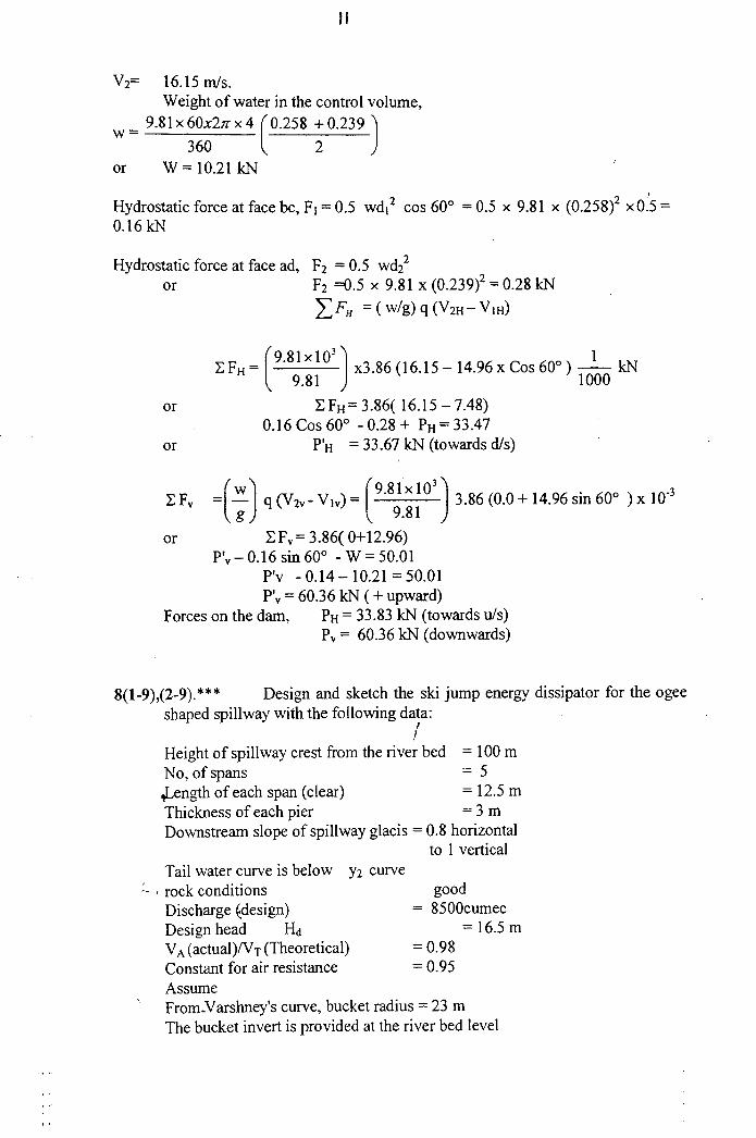
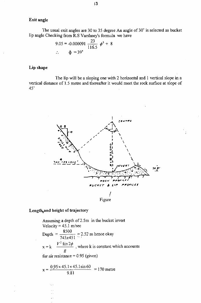
8.*** Design and sketch the ski jump energy dissipator for the ogee – shaped
spillway with the following data:
Height of spillway crest from river bed = 100 m
No. of spans = 5
Length of each span (clear) = 12.5 m
Thickness of each pier = 3 m
Downstream slope of spillway glacis = 0.8 horizontal to vertical
Tail water curve is below Y2 curve
Rock conditions good
Discharge (design) = 8500 cumecs
Design head Hd = 16.5 m
VA(actual)/ VT (theoretical) = 0.98
Constant for air resistance = 0.95
Assume from Varshney's curve bucket radius= 23 m
The bucket invert is provided at the river bed level assuming sound rock to be
2.0 m below the river bed.
How far and high is the trajectory?
(No need to compute the pressure on bucket and dynamic force.)
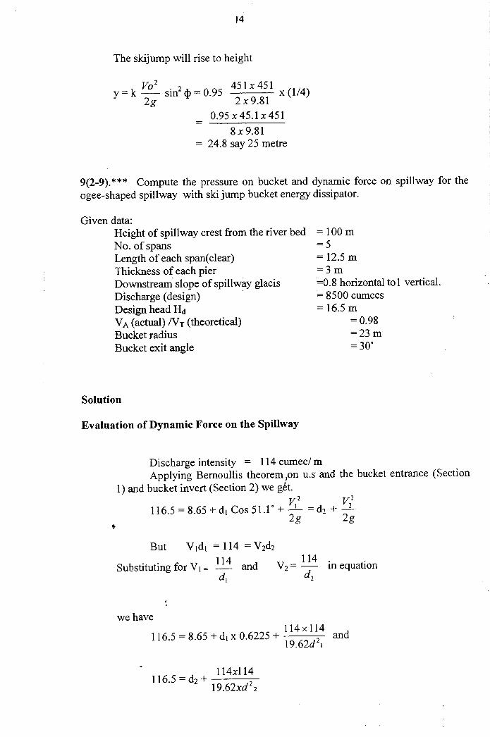
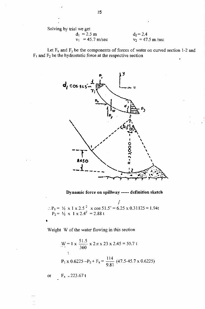
9.*** Compute the pressure on bucket and dynamic force on spillway for the ogee-
shaped spillway with ski jump bucket energy dissipator.
Given data:
Height of spillway crest from river bed = 100 m
No. of spans = 5
Length of each span (clear) = 12.5 m
Thickness of each pier = 3 m
Downstream slope of spillway glacis = 0.8 horizontal to vertical
Discharge (design) = 8500 cumecs
Design head Hd = 16.5 m
VA (actual)/VT (theoretical) = 0.98
Bucket radius = 23 m
Bucket exit angle = 30°
Chapter 3: Reservoir
1. What are different types of reservoirs? Explain the various purposes of
different types of reservoirs.
2. How would you estimate the available storage capacity of a reservoir? Draw
typical storage-elevation curve.
3. What are the different investigations required for reservoir planning?
4. What considerations will you have while selecting the site of a reservoir?
5. Explain the following terms:
(a) Full reservoir level (b) Maximum water level
(c) Minimum water level (d) Useful storage
(e) Surcharge storage (f) Dead storage
6. Discuss the analytical method for the determination of the storage capacity.
7. What are different types of losses in reservoir?
8. What are the various causes for the reservoir sedimentation? How would you
reduce the rate of sedimentation?
9. How would you estimate the useful life of a reservoir?
Chapter 4: Gravity Dam
1.* Enumerate the various forces acting on a gravity dam. How would you
determine the weight of the dam?
2.* What is an elementary profile of a gravity dam?
Derive an expression for the base width for (a) non – tension criterion (b) no
sliding criterion.
3.* What would be the maximum height of an elementary profile of a gravity if
the safe compressive stress for the masonry is 1.5 M Pa. Assume unit weight
of masonry on 23 KN/m3.
4.* Determine the uplift pressure force on a gravity dam of 40 m height, 10 m top
width, with u/s face vertical and the base width = 30 m. The tail water depth is
5 m and the free board is 3m.Determine the uplift pressure when there is a
drainage gallery at a distance of 6 m from u/s face.
5.** What are the different assumptions made in the stability analysis of a gravity
dam?
6.** What is the limiting height of low dam? Differentiate between the low and
high gravity dams.
7.** What are different types of joints in a gravity dam? Discuss the methods of
their construction and their advantages.
8.** Write short notes on : (a) keys (b) Water stops
9.** Draw a practical profile for a low gravity dam from the following data.
Height of dam = 31.5 m
Special weight of concrete = 24 kN/m3
Safe Compressive stress = 1.2 M Pa
Top width = 3.0 m
10.** A concrete gravity dam has the following data:
Maximum water level = 300.00
Bed level = 220.00
R.L top of dam = 304.00
The d/s slope of 0.67:1 starts at RL of 295.00
U/s face is vertical.
Center line of the drainage gallery = 8.0 m u/s face.
Consider only weight, water pressure and uplift.
Calculate the maximum vertical stresses at the toe and heel of the dam, assuming
100% uplift pressure at the heel and 50% at the gallery and zero at the toe.
11.** Find the force and moment due to earthquake acceleration of 0.1 g on a dam
of 150 m height and 110m width at base. The dam is trapezoidal in section,
with top width = 10 m.
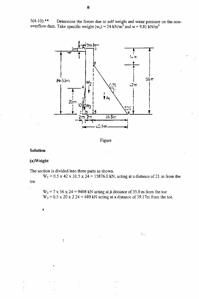
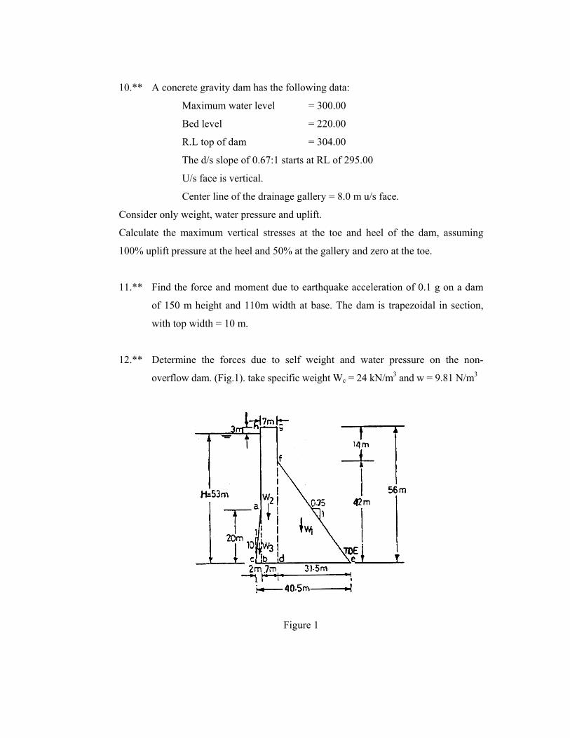
12.** Determine the forces due to self weight and water pressure on the non-
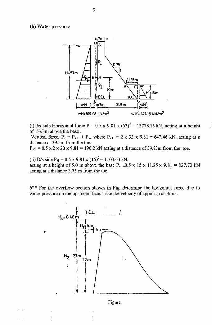
overflow dam. (Fig.1). take specific weight Wc = 24 kN/m3 and w = 9.81 N/m3
Figure 1
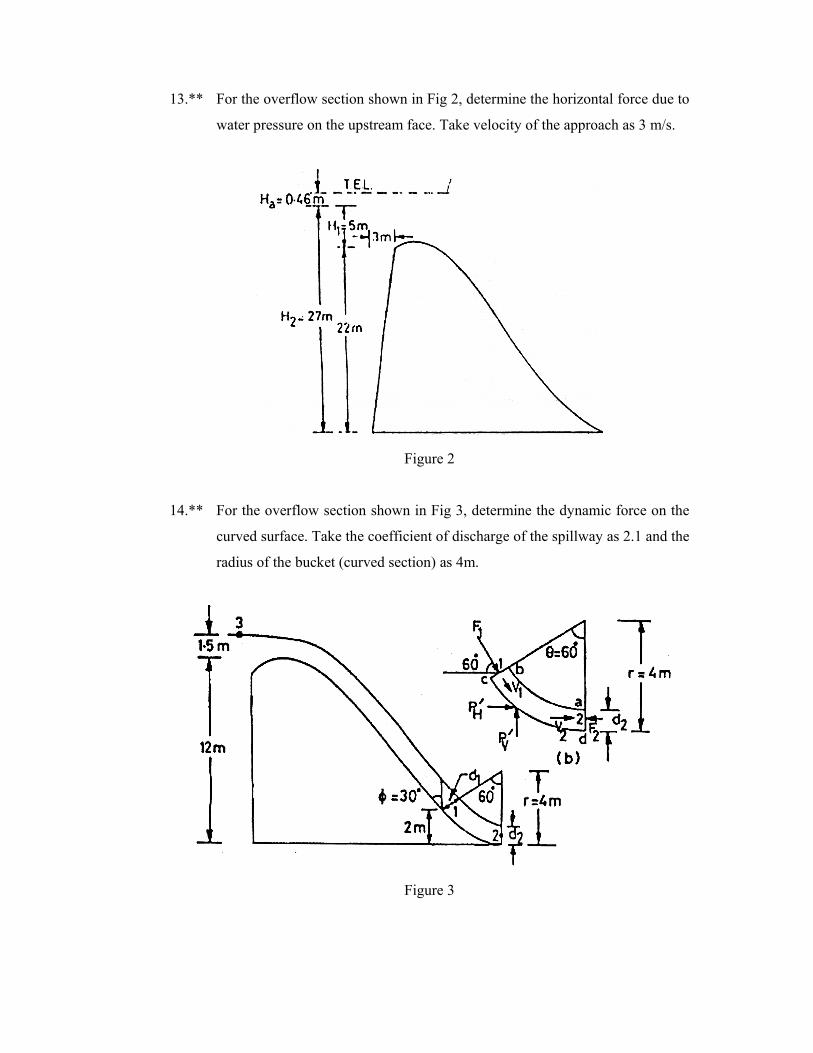
13.** For the overflow section shown in Fig 2, determine the horizontal force due to
water pressure on the upstream face. Take velocity of the approach as 3 m/s.
Figure 2
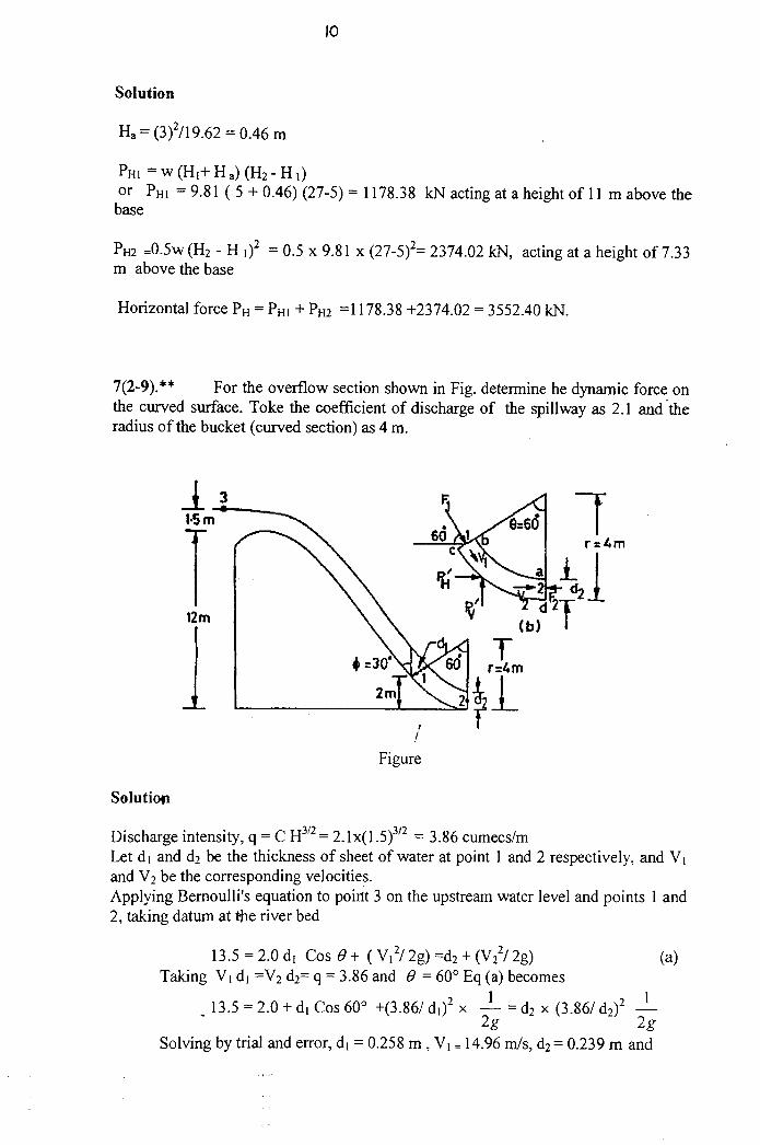
14.** For the overflow section shown in Fig 3, determine the dynamic force on the
curved surface. Take the coefficient of discharge of the spillway as 2.1 and the
radius of the bucket (curved section) as 4m.
Figure 3
15.*** Discuss the effect of earthquake accelerations on the water on the u / s and d/s
of the dam. How would you determine the hydrodynamic forces?
16.*** The following particulars refer to a concrete dam
R.L. of top of dam = 250.00
Free board = 3.0 m
U/s face is vertical
D/s face sloping at 0.7:1 from R.L 240.00.
R.L. of base = 210.00
Determine the stability of the dam and the stresses induced when the reservoir
is full. Take the unit weight of concrete as 24 kN/m3, µ = 0.70, safe
compressive stress = 2 M Pa, safe bearing capacity = 1.5 M Pa. Consider full
uplift.
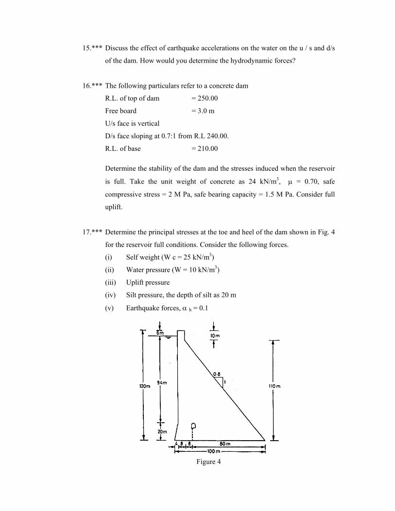
17.*** Determine the principal stresses at the toe and heel of the dam shown in Fig. 4
for the reservoir full conditions. Consider the following forces.
(i) Self weight (W c = 25 kN/m3)
(ii) Water pressure (W = 10 kN/m3)
(iii) Uplift pressure
(iv) Silt pressure, the depth of silt as 20 m
(v) Earthquake forces, α h = 0.1
Figure 4
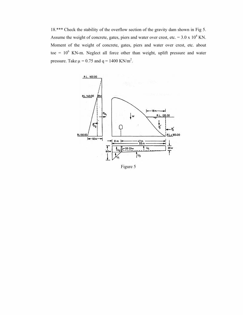
18.*** Check the stability of the overflow section of the gravity dam shown in Fig 5.
Assume the weight of concrete, gates, piers and water over crest, etc. = 3.0 x 10⁴ KN.
Moment of the weight of concrete, gates, piers and water over crest, etc. about
toe = 106 KN-m. Neglect all force other than weight, uplift pressure and water
pressure. Take µ = 0.75 and q = 1400 KN/m2.
Figure 5
Chapter 5 : Earth Dams
1.** What are various types of earth dams according to the section of the dam?
What type of section is commonly used in practice and why?
2.** Discuss the various causes of failure of earth dams. How would you prevent
different types of failures?
3.** How would you prevent piping failure in an earth dam?
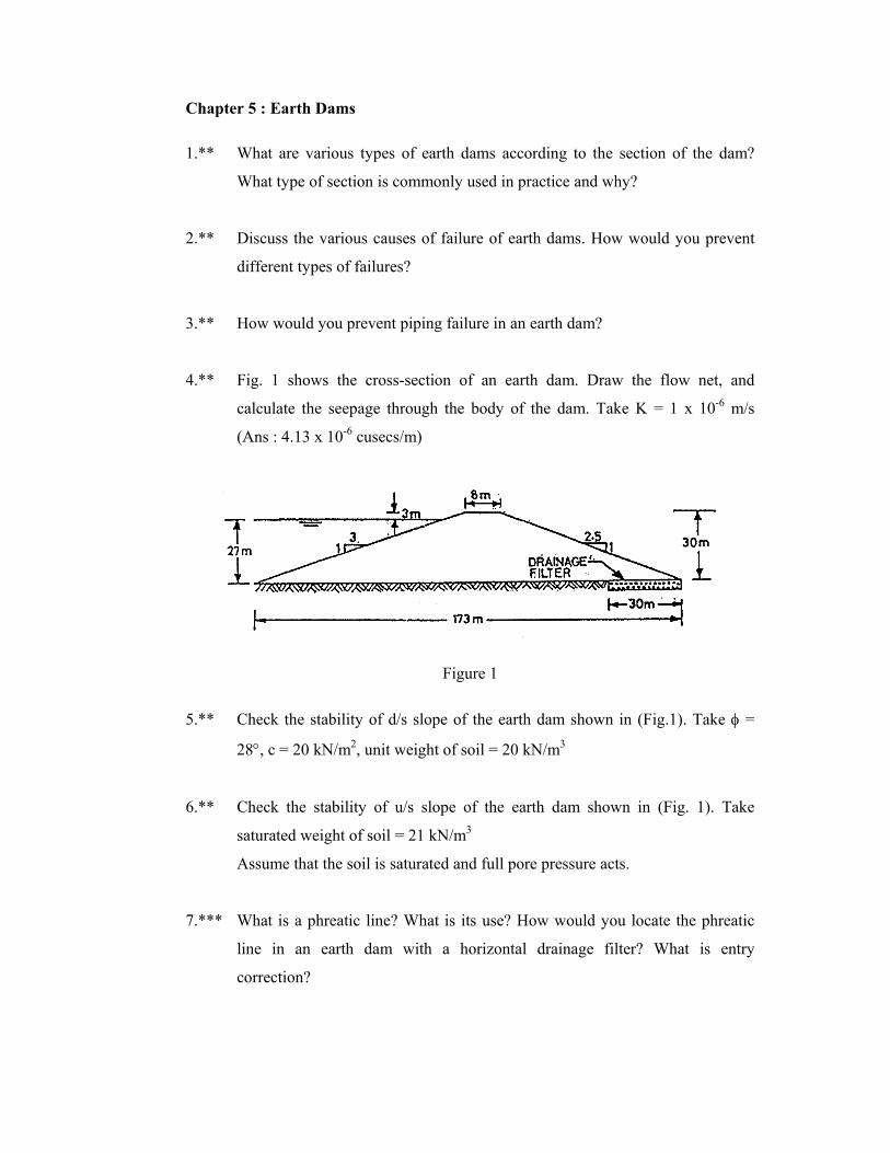
4.** Fig. 1 shows the cross-section of an earth dam. Draw the flow net, and
calculate the seepage through the body of the dam. Take K = 1 x 10⁻⁶ m/s
(Ans : 4.13 x 10⁻⁶ cusecs/m)
Figure 1
5.** Check the stability of d/s slope of the earth dam shown in (Fig.1). Take φ =
28°, c = 20 kN/m2, unit weight of soil = 20 kN/m3
6.** Check the stability of u/s slope of the earth dam shown in (Fig. 1). Take
saturated weight of soil = 21 kN/m3
Assume that the soil is saturated and full pore pressure acts.
7.*** What is a phreatic line? What is its use? How would you locate the phreatic
line in an earth dam with a horizontal drainage filter? What is entry
correction?
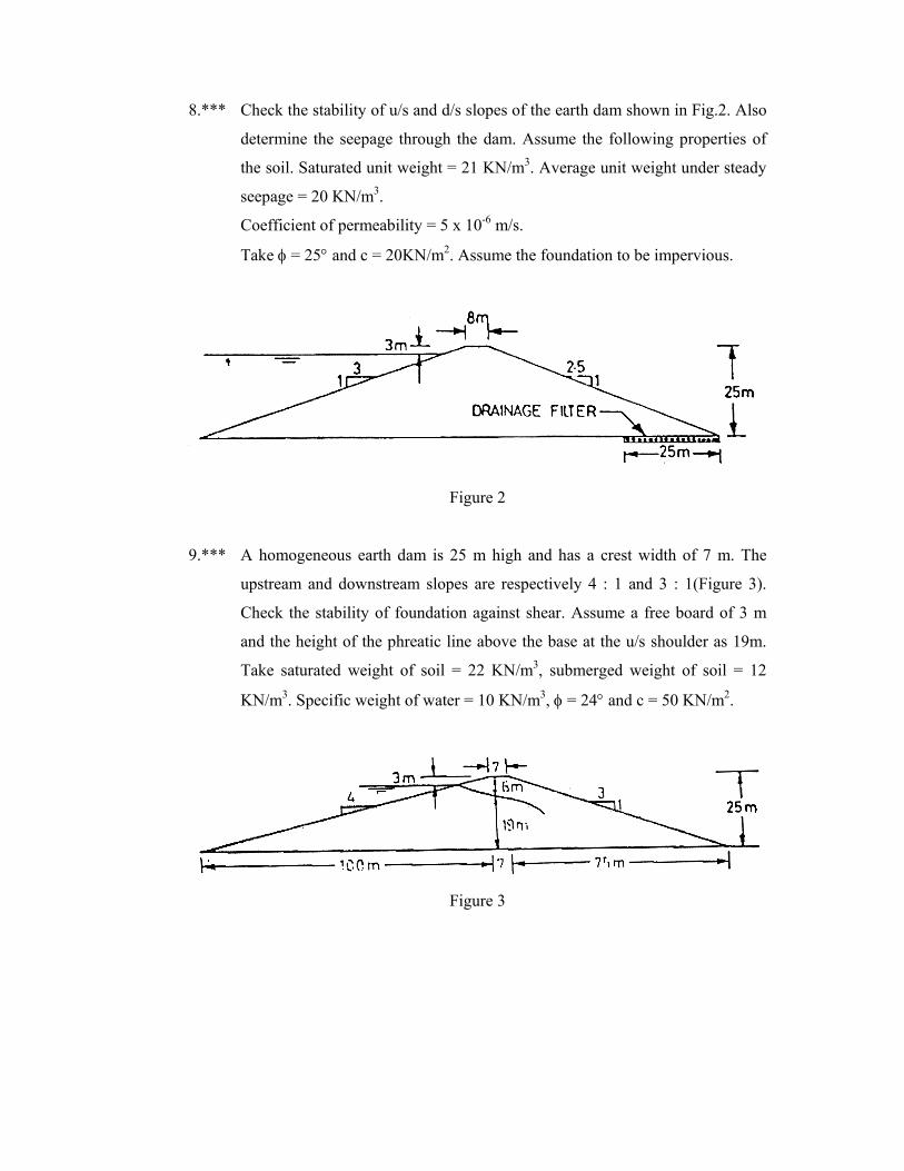
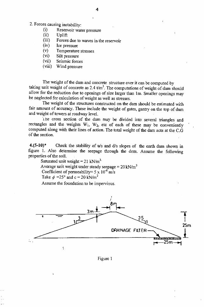
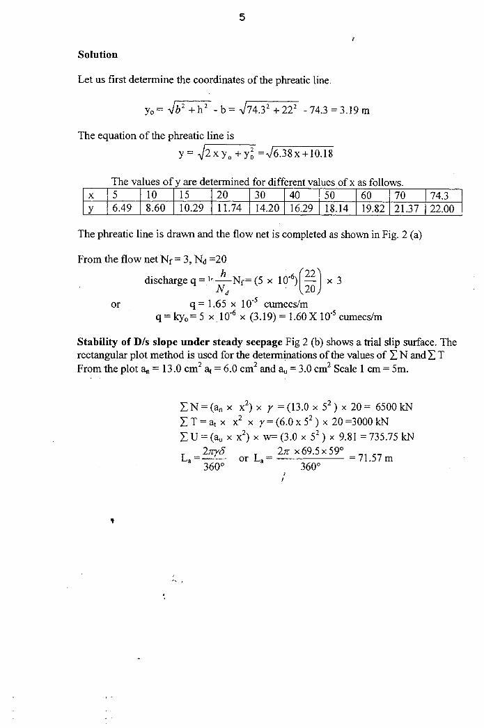
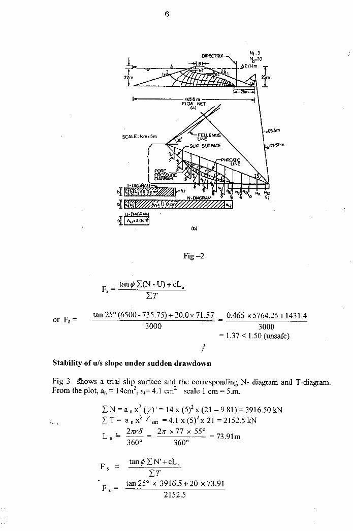
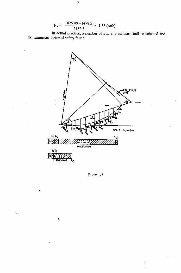
8.*** Check the stability of u/s and d/s slopes of the earth dam shown in Fig.2. Also
determine the seepage through the dam. Assume the following properties of
the soil. Saturated unit weight = 21 KN/m3. Average unit weight under steady
seepage = 20 KN/m3.
Coefficient of permeability = 5 x 10⁻⁶ m/s.
Take φ = 25° and c = 20KN/m2. Assume the foundation to be impervious.
Figure 2
9.*** A homogeneous earth dam is 25 m high and has a crest width of 7 m. The
upstream and downstream slopes are respectively 4 : 1 and 3 : 1(Figure 3).
Check the stability of foundation against shear. Assume a free board of 3 m
and the height of the phreatic line above the base at the u/s shoulder as 19m.
Take saturated weight of soil = 22 KN/m3, submerged weight of soil = 12
KN/m3. Specific weight of water = 10 KN/m3, φ = 24° and c = 50 KN/m2.
Figure 3
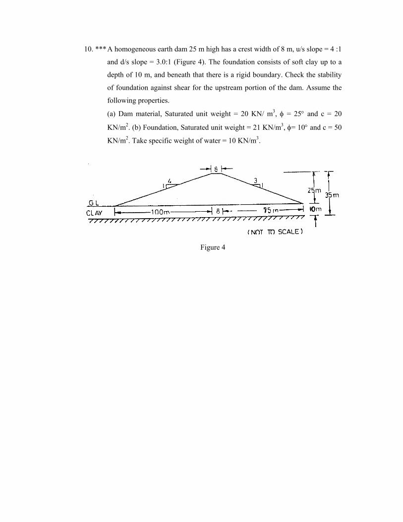
10. *** A homogeneous earth dam 25 m high has a crest width of 8 m, u/s slope = 4 :1
and d/s slope = 3.0:1 (Figure 4). The foundation consists of soft clay up to a
depth of 10 m, and beneath that there is a rigid boundary. Check the stability
of foundation against shear for the upstream portion of the dam. Assume the
following properties.
(a) Dam material, Saturated unit weight = 20 KN/ m3, φ = 25° and c = 20
KN/m2. (b) Foundation, Saturated unit weight = 21 KN/m3, φ= 10° and c = 50
KN/m2. Take specific weight of water = 10 KN/m3.
Figure 4
MINISTRY OF SCIENCE AND TECHNOLOGY
DEPARTMENT OF TECHNICAL AND VOCATIONAL EDUCATION
CE-05016 DESIGN OF HYDRAULIC STRUCTURES
Worked Out Examples
B.E.
Civil Engineering