Embed Size (px)
Citation preview

T-6B JPPT 1542.165A
Simulator Event Briefing Guide
JPPT 1542.165A Q3101
Sim
ula
tor
Event In
stru
cto
r Guid
e
PR
IMA
RY
AN
D IN
TE
RM
ED
IAT
E M
ULT
I-SE
RV
ICE
NF
O/W
SO
TR
AIN
ING
SY
ST
EM
Gra
din
g G
uid
elin
es –
I20
01
Q3101 Briefing Guide
(Worksheet)
Planned Route:
Takeoff: KNSE, Rwy 05 Altitude: Route:
MOA Limits South MOA
Training Device: OFT
SYLLABUS NOTES: Emphasis is on procedural knowledge and execution of procedures in accordance with the NATOPS Flight Manual.
IUT’s will reference the Emergency Landing Pattern Stall from the Contact FTI for procedural execution of Power Off Stall.
IUT’s will reference the Landing Pattern Stall from the Contact FTI for the procedural execution of Approach Turn Stall.
For Power-Off and Approach Turn Stalls, IUT’s shall demonstrate proficiency in stall recovery at both first indication of impending stall and onset of stall.
Utilize the Abbreviated Simulator Checklist.
Special Syllabus Requirement None
Discuss
a. Ground Operations Simulator Abbreviated Checklist Answer any questions (FWOP Chap 3)
b. Departure Runway 05/14 Runway 23/32
North MOA Pelican Working Area South MOA
c. Approach Turn Stall Stalls in general Landing Pattern (Approach Turn) Stall (Contact FTI)
Primary area for NATOPS phase
or North MOA
Ejection Seat Sequence Mitigation Procedures

JPPT 1542.165A Q3101
d. Spin Steady State Indications Erect Spin Recovery OCF Recovery
e. Power Off Stall Power-Off Stall (ELP Stall) (Contact FTI)
f. Slips Procedures (Contact FTI)
g. Course Rules North Recovery to Conecuh River Bridge North Recovery to Point Jay Pattern Operations 05/14 23/32
h. Radio Procedures Use the FWOP as resource for local communications
i. HUD Currently under a waiver from CNATRA
VFR return from Area 1
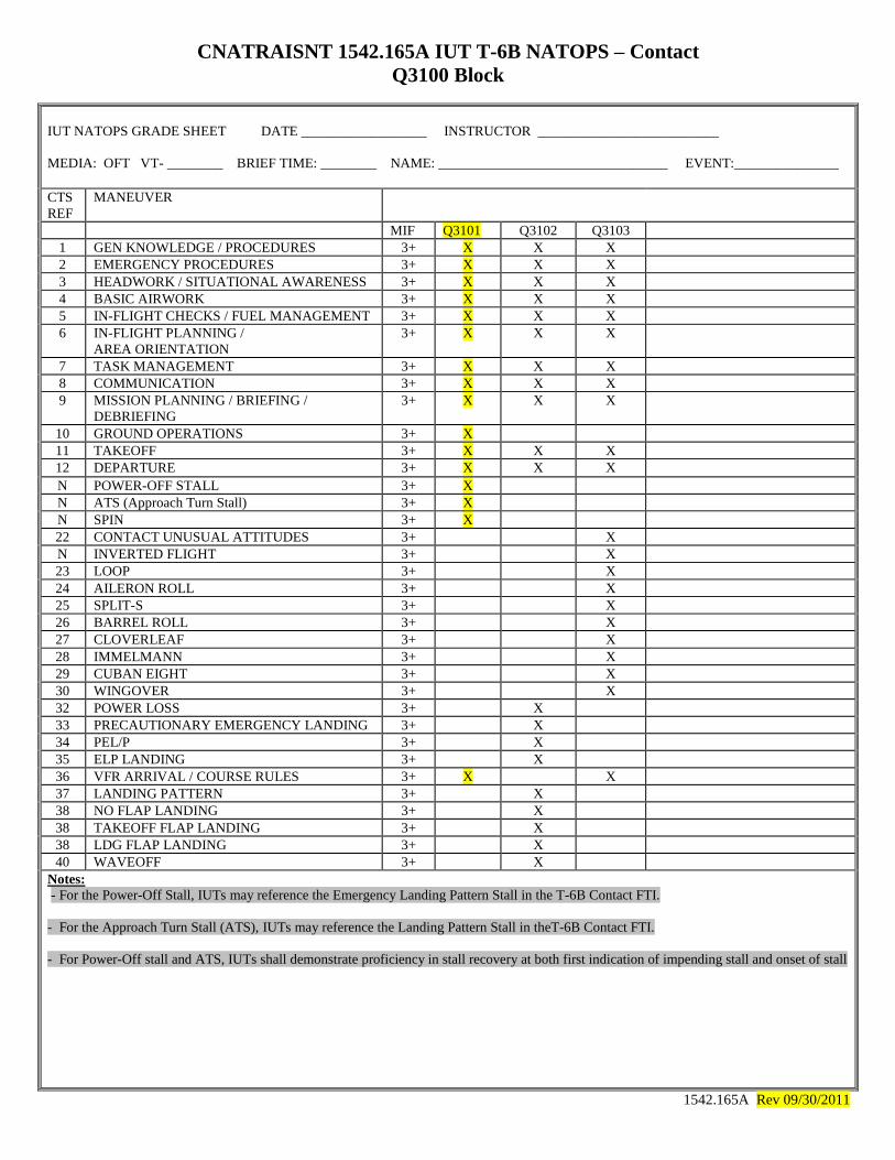
CNATRAISNT 1542.165A IUT T-6B NATOPS – Contact
Q3100 Block
IUT NATOPS GRADE SHEET DATE __________________ INSTRUCTOR __________________________
MEDIA: OFT VT- ________ BRIEF TIME: ________ NAME: _________________________________ EVENT:_______________
CTS
REF
MANEUVER
MIF Q3101 Q3102 Q3103
1 GEN KNOWLEDGE / PROCEDURES 3+ X X X
2 EMERGENCY PROCEDURES 3+ X X X
3 HEADWORK / SITUATIONAL AWARENESS 3+ X X X
4 BASIC AIRWORK 3+ X X X
5 IN-FLIGHT CHECKS / FUEL MANAGEMENT 3+ X X X
6 IN-FLIGHT PLANNING /
AREA ORIENTATION
3+ X X X
7 TASK MANAGEMENT 3+ X X X
8 COMMUNICATION 3+ X X X
9 MISSION PLANNING / BRIEFING /
DEBRIEFING
3+ X X X
10 GROUND OPERATIONS 3+ X
11 TAKEOFF 3+ X X X
12 DEPARTURE 3+ X X X
N POWER-OFF STALL 3+ X
N ATS (Approach Turn Stall) 3+ X
N SPIN 3+ X
22 CONTACT UNUSUAL ATTITUDES 3+ X
N INVERTED FLIGHT 3+ X
23 LOOP 3+ X
24 AILERON ROLL 3+ X
25 SPLIT-S 3+ X
26 BARREL ROLL 3+ X
27 CLOVERLEAF 3+ X
28 IMMELMANN 3+ X
29 CUBAN EIGHT 3+ X
30 WINGOVER 3+ X
32 POWER LOSS 3+ X
33 PRECAUTIONARY EMERGENCY LANDING 3+ X
34 PEL/P 3+ X
35 ELP LANDING 3+ X
36 VFR ARRIVAL / COURSE RULES 3+ X X
37 LANDING PATTERN 3+ X
38 NO FLAP LANDING 3+ X
38 TAKEOFF FLAP LANDING 3+ X
38 LDG FLAP LANDING 3+ X
40 WAVEOFF 3+ X
Notes:
- For the Power-Off Stall, IUTs may reference the Emergency Landing Pattern Stall in the T-6B Contact FTI.
- For the Approach Turn Stall (ATS), IUTs may reference the Landing Pattern Stall in theT-6B Contact FTI.
- For Power-Off stall and ATS, IUTs shall demonstrate proficiency in stall recovery at both first indication of impending stall and onset of stall
1542.165A Rev 09/30/2011

The following checklist is to be used ONLY in the T-6B Simulators when the
entire checklist completion is not required due to time constraints.
T-6B SIMULATOR EVENTS ABBREVIATED GROUND PROCEDURES CHECKLIST
(SIMULATORS ONLY) Initial cockpit set up: Adjust seat height and rudder pedals; Batt,
Gen, Aux Batt on; Avionics master on; Bleed air inflow norm; O2 normal; TAD on; TCAS on
BEFORE TAXI 17. UFCP AND MFD’S b. UHF………………………………………………… Copy ATIS and Clearance c. VHF COM………………………………………………………. Set as Required d. VOR…………………………..……………………………….... Set as Required e. Transponder………………..……………………………..….. SET, STANDBY f. FMS………………………………………………..…………….. Set as Required g. Alt, G, Speed, Fuel flags…. ……………..…………….. Set as Required 19. ALTIMETERS…………………____SET AND CHECKED TWICE (BOTH)
Call for TAXI
BEFORE TAKEOFF 3. FLAPS……………………………………….………………………………. TAKEOFF 4. TRIM………………………………………………..…………….SET for TAKEOFF 11. SEAT SAFETY PIN…………...……. REMOVED AND STOWED (BOTH) 12. ISS MODE SELECTOR………………………….…. BOTH, ROGER BOTH
Call for TAKEOFF
LINEUP CHECKLIST 1. EXTERIOR LIGHTS ………………..…………..……………………..…………. ON 2. TRANSPONDER ………………………………….………………………ALTITUDE 3. PROBES ANTI-ICE SWITCH ………………..……….………………..………ON 4. NOSE WHEEL STEERING ……….…….……..………....……….…………..OFF 5. EICAS DISPLAY ……………………………………………… CHECKED (BOTH) Flight Manual Change4: 01 June 2015 Rev: Sep 2015
Flight Manual Change 4; 01 JUNE 2015 September 2015

VFR Course Rules Departures – RWY 5/14
9
HWY 4
12 DME
ENSLY
24 DME
I-10
10 DME
VFR Course Rules Departures – RWY 5/14
After takeoff:
- On departure, turn to a heading of 010°.
- Level off at 700’- 800’ MSL until clear of pattern.
- Climb at 180 KIAS and contact Pensacola Departure CH 6.
- North MOA/South MOA: Comply with stereo routing and altitude.
- VFR to the West, Fox or North: Climb to 4,500’ MSL. When instructed by ATC
to “proceed on course” or when passing 4,200’ MSL, turn to heading:
-Pelican (North): 360°.
-Area 1 (West): 270°.
-Area Fox (Northwest): 270°-320°.
-Area 3 (South): When cleared by ATC turn to 180°.
- When instructed by ATC to “climb to requested VFR altitude” climb to:
-Pelican (North): 5,500’ MSL.
-Area 1 (West): 6,500’ MSL.
-Area Fox (Northwest): 4,500’ MSL.
-Area 3 (South): Maintain 4,500’ MSL. ATC will advise further climbs.
Maintain radar advisories until reaching the following termination points
Pelican (North): HWY 4 (NSE 12 DME).
Area 1 (West): Point ENSLY (NSE 24 DME)/(N/S railroad ivo Bay Springs).
Area Fox (NW): HWY 29 (NSE 17 DME).
Area 3 (South): I-10 (NSE 10 DME).*
*If conducting aerobatics or OCF in Area 3, maintain assigned squawk when crossing I-10 for VFR flight
following. Do not call clear to the south or cancel radar advisories. Radios should be tuned to Area 3
Common (19) & Pensacola Approach when directed.
9
HWY 4
12 DME
I-10
10 DME
010°
4,500’ MSL
4,500’ MSL. 270° 4,500’ MSL. 270°
After takeoff:
- On departure, turn to a heading of 010°.
- Level off at 700’- 800’ MSL until clear of pattern.
- Climb at 180 KIAS and contact Pensacola Departure CH 6.
- North MOA/South MOA: Comply with stereo routing and altitude.
- VFR to the West, Fox or North: Climb to 4,500’ MSL. When instructed by ATC
to “proceed on course” or when passing 4,200’ MSL, turn to heading:
-Pelican (North): 360°.
-Area 1 (West): 270°.
-Area Fox (Northwest): 270°-320°.
-Area 3 (South): When cleared by ATC turn to 180°.
- When instructed by ATC to “climb to requested VFR altitude” climb to:
-Pelican (North): 5,500’ MSL.
-Area 1 (West): 6,500’ MSL.
-Area Fox (Northwest): 4,500’ MSL.
-Area 3 (South): Maintain 4,500’ MSL. ATC will advise further climbs.
Maintain radar advisories until reaching the following termination points
Pelican (North): HWY 4 (NSE 12 DME).
Area 1 (West): Point ENSLY (NSE 24 DME)/(N/S railroad ivo Bay Springs).
Area Fox (NW): HWY 29 (NSE 17 DME).
Area 3 (South): I-10 (NSE 10 DME).*
*If conducting aerobatics or OCF in Area 3, maintain assigned squawk when crossing I-10 for VFR flight
following. Do not call clear to the south or cancel radar advisories. Radios should be tuned to Area 3
Common (19) & Pensacola Approach when directed.
ENSLY
24 DME
4,500’ MSL.
180° when cleared. 4500’ MSL
180° when cleared.
010°
4,500’ MSL
COMTRAWINGFIVEINST 3710.3 COMTRAWINGFIVEINST 3710.3
6,500’ MSL when cleared.
Area 1
>4,200’
Pelican Pelican
4,500’ MSL
360°
5,500’ MSL when
cleared.
>4,200’ Area 1
6,500’ MSL when cleared.
4,500’ MSL
360°
5,500’ MSL when
cleared
OCTOBER 2015 OCTOBER 2015

After takeoff:
- On departure, turn to a heading of 340°.
- Level off at 700’- 800’ MSL until clear of pattern.
- Climb at 180 KIAS and contact Pensacola Departure CH 6.
- North MOA/South MOA: Comply with stereo routing and altitude.
- VFR to the West, Fox or North: Climb to 4,500’ MSL. When instructed by ATC
to “proceed on course” or when passing 4,200’ MSL, turn to heading:
-Pelican (North): 360°.
-Area 1 (West): 270°.
-Area Fox (Northwest): 270°-320°.
-Area 3 (South): When cleared by ATC turn to 180°.
- When instructed by ATC to “climb to requested VFR altitude” climb to:
-Pelican (North): 5,500’ MSL.
-Area 1 (West): 6,500’ MSL.
-Area Fox (Northwest): 4,500’ MSL.
-Area 3 (South): Maintain 4,500’ MSL. ATC will advise further climbs.
Maintain radar advisories until reaching the following termination points
Pelican (North): HWY 4 (NSE 12 DME).
Area 1 (West): Point ENSLY (NSE 24 DME)/(N/S railroad ivo Bay Springs).
Area Fox (NW): HWY 29 (NSE 17 DME).
Area 3 (South): I-10 (NSE 10 DME).*
*If conducting aerobatics or OCF in Area 3, maintain assigned squawk when crossing I-10 for VFR flight
following. Do not call clear to the south or cancel radar advisories. Radios should be tuned to Area 3
Common (19) & Pensacola Approach when directed.
10
HWY 4
12 DME
ENSLY
24 DME
340°
4,500’ MSL
4500’ MSL. 270°
4500’ MSL.
180° when
cleared.
VFR Course Rules Departures – RWY 23/32 VFR Course Rules Departures – RWY 23/32
COMTRAWINGFIVEINST 3710.3 COMTRAWINGFIVEINST 3710.3
4500’ MSL.
180° when
cleared.
Area 1 Area 1
Pelican Pelican
4,500’ MSL
360°
5,500’ MSL when
cleared.
4,500’ MSL
360°
5,500’ MSL when
cleared.
6,500’ MSL when cleared. 6,500’ MSL when cleared. >4,200’ >4,200’
I-10
10 DME
I-10
10 DME
OCTOBER 2015 OCTOBER 2015

Block Altitudes MSL
GATOR & ATCAA 10,500’ – FL 230
LOW
(3A N/A LOW) 10,500’ – 16,500’ MSL
HIGH 17,000’ – FL 230
Frequencies
Pensacola App
(MOA monitor)
372.0 / 120.05
(28)
MOA Discrete 360.725 (29)
22
South MOA – GATOR Area (VFR)
Entry/Transition
- File SMOA canned route for entry. (NSE 5
from NSE).
- Use local altimeter, when it is below 29.92
use FL 220 as top of working area.
- PNS App (MOA Monitor) will transition
aircraft to/from assigned block(s) and issue
GATOR clearance:
- Gator clearance authorizes aircraft to
climb/descend from assigned alt only once
established in the lateral confines of
assigned working block Stay below
10,500’ MSL until in working block.
- Monitor 360.725 (CH 29) while in the
GATOR area.
Exit (VFR)
- Contact PNS App 120.05/372.0 (CH 28)
“Pensacola App, (call sign) cancel radar
advisories”
- Remain within assigned block until given
instruction by PNS App (MOA Monitor).
- Aircraft descending from high blocks
through low block will do so only after ATC
instructions, via MOA section lines or
through cold areas.
- Aircraft requesting VFR flight following after
departing the GATOR will do so 10 minutes
prior to departure.
Block Altitudes MSL
GATOR & ATCAA 10,500’ – FL 230
LOW
(3/A N/A LOW) 10,500’ – 16,500’ MSL
HIGH 17,000’ – FL 230
22
South MOA – GATOR Area (VFR)
Entry/Transition
- File SMOA canned route for entry. (NSE 5
from NSE).
- Use local altimeter, when it is below 29.92
use FL 220 as top of working area.
- PNS App (MOA Monitor) will transition
aircraft to/from assigned block(s) and issue
GATOR clearance:
- Gator clearance authorizes aircraft to
climb/descend from assigned alt only once
established in the lateral confines of
assigned working block Stay below
10,500’ MSL until in working block.
- Monitor 360.725 (CH 29) while in the
GATOR area.
Exit (VFR)
- Contact PNS App 120.05/372.0 (CH 28)
“Pensacola App, (call sign) cancel radar
advisories”
- Remain within assigned block until given
instruction by PNS App (MOA Monitor).
- Aircraft descending from high blocks
through low block will do so only after ATC
instructions, via MOA section lines or
through cold areas.
- Aircraft requesting VFR flight following after
departing the GATOR will do so 10 minutes
prior to departure.
Frequencies
Pensacola App
(MOA monitor)
372.0 / 120.05
(28)
MOA Discrete 360.725 (29)
COMTRAWINGFIVEINST 3710.3 COMTRAWINGFIVEINST 3710.3 OCTOBER 2015 OCTOBER 2015
KNSE (4)
KNFJ (24)
KNSE (4)
KNFJ (24) KPNS (54) KPNS (54)
KNPA (44) KNPA (44)
Line Alpha
A
Line Bravo
B
Line Charlie
C
Line 1
D
Line Alpha
A
Line Bravo
B
Line Charlie
C
Line 1
D
Line 2
E Line 2
E
I I
H H
F F
KJKA (122.7)
KNBJ (9)
KNFD (10)
Saufley
KCQF (123.0)
Saufley
KNFD (10)
KNBJ (9)
KJKA (122.7)
KCQF (123.0)
KBFM (64)
1R8 (122.8) 1R8 (122.8)
KBFM (64) Silverhill Silverhill
1A 1B 1C 1D
2A 2B 2C
2D
3A 3B
3C 3D
1A 1B 1C 1D
2A 2B 2C
2D
3A 3B
3C 3D
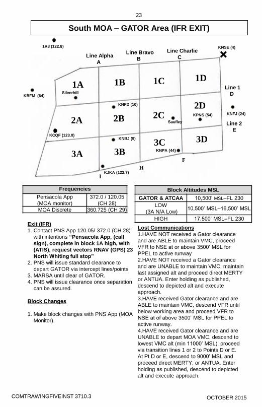
Block Altitudes MSL
GATOR & ATCAA 10,500’ MSL–FL 230
LOW
(3A N/A Low) 10,500’ MSL–16,500’ MSL
HIGH 17,500’ MSL–FL 230
Frequencies
Pensacola App
(MOA monitor)
372.0 / 120.05
(CH 28)
MOA Discrete 360.725 (CH 29)
23
South MOA – GATOR Area (IFR EXIT)
Exit (IFR)
1. Contact PNS App 120.05/ 372.0 (CH 28)
with intentions “Pensacola App, (call
sign), complete in block 1A high, with
(ATIS), request vectors RNAV (GPS) 23
North Whiting full stop”
2. PNS will issue standard clearance to
depart GATOR via intercept lines/points
3. MARSA until clear of GATOR.
4. PNS will issue clearance once separation
can be assured.
Block Changes
1. Make block changes with PNS App (MOA
Monitor).
Lost Communications
1.HAVE NOT received a Gator clearance
and are ABLE to maintain VMC, proceed
VFR to NSE at or above 3500’ MSL for
PPEL to active runway
2.HAVE NOT received a Gator clearance
and are UNABLE to maintain VMC, maintain
last assigned alt and proceed direct MERTY
or ANTUA. Enter holding as published,
descend to depicted alt and execute
approach.
3.HAVE received Gator clearance and are
ABLE to maintain VMC, descend VFR until
below working area and proceed VFR to
NSE at of above 3500’ MSL for PPEL to
active runway.
4.HAVE received Gator clearance and are
UNABLE to depart MOA VMC, descend to
lowest VMC alt (min 11000’ MSL), proceed
via transition lines 1 or 2 to Points D or E.
At Pt D or E, descend to 9000’ MSL and
proceed direct MERTY, or ANTUA. Enter
holding as published, descend to depicted
alt and execute approach.
Block Altitudes MSL
GATOR & ATCAA 10,500’ MSL–FL 230
LOW
(3A N/A Low) 10,500’ MSL–16,500’ MSL
HIGH 17,500’ MSL–FL 230
Frequencies
Pensacola App
(MOA monitor)
372.0 / 120.05
(CH 28)
MOA Discrete 309.8 (CH 29)
23
South MOA – GATOR Area (IFR EXIT)
Exit (IFR)
1. Contact PNS App 120.05/ 372.0 (CH 28)
with intentions “Pensacola App, (call
sign), complete in block 1A high, with
(ATIS), request vectors RNAV (GPS) 23
North Whiting full stop”
2. PNS will issue standard clearance to
depart GATOR via intercept lines/points
3. MARSA until clear of GATOR.
4. PNS will issue clearance once separation
can be assured.
Block Changes
1. Make block changes with PNS App (MOA
Monitor).
Lost Communications
1.HAVE NOT received a Gator clearance
and are ABLE to maintain VMC, proceed
VFR to NSE at or above 3500’ MSL for
PPEL to active runway
2.HAVE NOT received a Gator clearance
and are UNABLE to maintain VMC, maintain
last assigned alt and proceed direct MERTY
or ANTUA. Enter holding as published,
descend to depicted alt and execute
approach.
3.HAVE received Gator clearance and are
ABLE to maintain VMC, descend VFR until
below working area and proceed VFR to
NSE at of above 3500’ MSL for PPEL to
active runway.
4.HAVE received Gator clearance and are
UNABLE to depart MOA VMC, descend to
lowest VMC alt (min 11000’ MSL), proceed
via transition lines 1 or 2 to Points D or E.
At Pt D or E, descend to 9000’ MSL and
proceed direct MERTY, or ANTUA. Enter
holding as published, descend to depicted
alt and execute approach.
COMTRAWINGFIVEINST 3710.3 COMTRAWINGFIVEINST 3710.3 OCTOBER 2015 OCTOBER 2015
KNSE (4) KNSE (4)
KNFJ (24) KNFJ (24) KPNS (54)
KPNS (54)
KNPA (44) KNPA (44)
Line Alpha
A
Line Alpha
A
Line Bravo
B
Line Bravo
B
Line Charlie
C
Line Charlie
C
Line 1
D
Line 1
D
Line 2
E
Line 2
E
I I
H H
F F
KBFM (64) KBFM (64)
1R8 (122.8) 1R8 (122.8)
Silverhill Silverhill
KCQF (123.0) KCQF (123.0)
KJKA (122.7) KJKA (122.7)
KNBJ (9) KNBJ (9)
KNFD (10) KNFD (10)
Saufley Saufley
1A 1A 1B 1B 1C 1C 1D 1D
2A 2A 2B 2B 2C 2C 2D 2D
3A 3B 3B 3A
3C 3C 3D 3D

Block Altitudes MSL
12000’ MSL 17,999’ MSL
Transition Block
EAST : 11700’ MSL
WEST: 11200’ MSL
Frequencies
JAX C Discrete 338.3 / 134.15 (CH 16)
JAX Center 346.2 / 120.2 (CH 17)
MOA Common 371.9 (CH 15)
North MOA
17
MVC
116.8
CEW
115.9
1A
1B 1C
2A 2B
2C
3A 3B
3C
4A 4B
4C
NSE
112.3
Block Altitudes MSL
12000’ MSL 17,999’ MSL
Transition Block
EAST : 11700’ MSL
WEST: 11200’ MSL
North MOA
17
MVC
116.8
CEW
115.9
1A
1B 1C
2A 2B
2C
3A 3B
3C
4A 4B
4C
NSE
112.3
Frequencies
JAX C Discrete 338.3 / 134.15 (CH 16)
JAX Center 346.2 / 120.2 (CH 17)
MOA Common 371.9 (CH 15)
COMTRAWINGFIVEINST 3710.3 COMTRAWINGFIVEINST 3710.3 OCTOBER 2015 OCTOBER 2015

North MOA
18
NORTH MOA PROCEDURES
NSE VFR/IFR
- VFR: File NSE2. Fly normal VFR departure.
- IFR: File NSE1, attempt VMC above.
- Expect climb to 4,000 ‘MSL and expect further clearance to 10,000’ MSL.
- Do not climb past assigned altitudes until specifically cleared by ATC.
- At or below 10,000’ MSL TRACON will direct switch to JAX Ctr on 338.3/134.15 (16)
- JAX Ctr will assign a working block after the pilot’s request.
- Aircraft will proceed to working block via appropriate transition altitudes until within
the lateral confines of assigned block.
- Switch to NMOA Common, 371.9 (15) once established if not already on frequency.
- Continue to monitor NMOA common and operate MARSA VMC between 12000’
MSL and 17,999’ MSL.
- IFR departure procedures same as VFR departure.
- IFR clearance is automatically canceled upon entering the MOA.
DO NOT ENTER MOA IMC without IFR clearance from JAX center. If unable to
maintain VMC in MOA, coordinate with JAX center for further clearance.
RECOVERIES FROM NORTH MOA
VFR
- Contact JAX center on 338.3 / 134.15 (16) and make applicable radio calls.
- JAX Ctr will advise to call passing 12,000’ MSL.
- Contact JAX Ctr passing 12,000’ MSL and follow ATC instruction to squawk 1200
and radar service will be terminated.
- Proceed VFR on applicable frequency and depart either laterally, through Pelican
Blocks 1B or 4C, coordinate a descent through another Pelican block, or descend
along Pelican Lines.
- If departing IFR, aircraft will maintain VMC at lowest altitude between 10,000’ MSL
and 17,999 MSL.
- Contact JAX center on 338.3 / 134.15 (16) with intentions/request.
- JAX center will issue a clearance to depart NMOA IFR when separation.
- Expect hand-off to Pensacola Approach.
IFR
- When ready to depart IFR make applicable radio call to JAX Ctr while maintaining
confines of assigned block.
- JAX Ctr will give clearance to destination with instruction for route of flight and
descent to 11,000’ MSL.
- Aircraft will stay within the confines of their working block and MARSA until reaching
11,000’ MSL AND THEN proceed as cleared.
- IFR clearance does not begin until within the lateral confines of the penetration area
and is based on JAX center workload.
MARSA PROCEDURES - NMOA
If JAX Ctr is unable to provide monitoring of NMOA, then Military Accepts
Responsibility of Separation of Traffic. Flight into the NMOA is permitted but VMC
must be maintained and all other normal airspace rules apply.
If North Field is VFR
- Make normal VFR departure and when canceling advisories, Squawk 1200 and
enter NMOA VFR. Maintain VMC and monitor NMOA Common 371.9 (15).
- For departing NMOA make departure still employing same airspace rules and either
join Course Rules or Random Arrival.
If North Field is IFR
- Depart with NSE 1T and once VMC cancel IFR and Squawk 1200. Climb and
maintain VFR in NMOA and monitor NMOA Common 371.9 (15).
- Depart NMOA same as VFR and pick up IFR clearance as necessary once clear of
NMOA.
COMTRAWINGFIVEINST 3710.3 COMTRAWINGFIVEINST 3710.3 OCTOBER 2015 OCTOBER 2015

Block Altitudes MSL
6000’ MSL 11,000’ MSL
Transition Block
EAST : 5700’ MSL
WEST: 5200’ MSL
Frequencies
Pelican & Fox
Common
254.9(12)
Evergreen 254.35 (14)
Brewton 257.97 (13)
Bay Minette 122.8 CTAF(27)
Monroeville 123.0 CTAF
Area 2T 254.9 (12)
Block Altitudes MSL
6000’ MSL 11,000’ MSL
Transition Block
EAST : 5700’ MSL
WEST: 5200’ MSL
Frequencies
Pelican & Fox
Common
254.9(12)
Evergreen 254.35 (14)
Brewton 257.97 (13)
Bay Minette 122.8 CTAF(27)
Monroeville 123.0 CTAF
Area 2T 254.9 (12)
19
Pelican Working Area
- Aircraft operating in the Pelican Working Area are VFR without radar advisories.
- Aerobatics: Squawk 4700.
- Blocks 1B and 4C are for ingress and egress of the airspace only.
ENTRY & EXIT
- Aircraft should enter and exit via the transition layer.
- If necessary, transit along block borders and make traffic calls on common BEFORE
traversing the borders to ensure deconfliction.
MVC
116.8
CEW
115.9
1A
1B 1C
2A 2B
2C
3A 3B
3C
4A 4B 4C
NSE
112.3
19
Pelican Working Area
- Aircraft operating in the Pelican Working Area are VFR without radar advisories.
- Aerobatics: Squawk 4700.
- Blocks 1B and 4C are for ingress and egress of the airspace only.
ENTRY & EXIT
- Aircraft should enter and exit via the transition layer.
- If necessary, transit along block borders and make traffic calls on common BEFORE
traversing the borders to ensure deconfliction.
MVC
116.8
CEW
115.9
1A
1B 1C
2A 2B
2C
3A
3B
3C
4A 4B
4C
NSE
112.3
12J
KGZH
Pt Jay
5 Lakes
Pt Jay
12J
5 Lakes
KGZH
Bridge Bridge
Pt Nugget Pt Nugget
COMTRAWINGFIVEINST 3710.3 COMTRAWINGFIVEINST 3710.3 OCTOBER 2015 OCTOBER 2015

CHAPTER FIVE PRIMARY CONTACT
5-20 FLIGHT PROCEDURES
514. STALLS
1. Description. Stalls are taught to develop your ability to recognize a complete stall or an
approaching stall and to recover correctly with a minimum loss of altitude.
2. General. You will learn to recognize the approaching stall or complete stall through a
combination of the senses of sight, sound and feel.
a. Vision is useful in detecting a stall condition by noting the attitude of the airplane.
This sense can be fully relied on only when the stall is the result of an unusual
attitude of the airplane. However, since the airplane can also be stalled from a normal
attitude, vision in this instance would be of little help in detecting the approaching
stall.
b. Hearing is also helpful in sensing a stall condition, since the tone level and intensity
of sounds incident to flight decrease as the airspeed decreases. The reduction of the
noise made by the air flowing along the canopy as airspeed decreases is also quite
noticeable, and when the stall is almost complete, vibration and its incident noises
often increase greatly.
c. Kinesthesia, or the sensing of change in direction or speed of motion, is probably the
most important and the best indicator to the trained and experienced pilot. If this
sensitivity is properly developed, it will warn of a decrease in speed or the beginning
of a settling or "mushing" of the airplane.
d. The feeling of control pressures is also very important. As speed is reduced, the
resistance to pressures on the controls becomes progressively less. Aircraft response
to control movements also decreases until a complete stall, when all controls can be
moved with almost no resistance, and with little immediate effect on the airplane.
The Stick shaker will normally occur 5-10 knots prior to the stall, with airframe
buffet occurring almost immediately thereafter. The stick shaker may sometimes
mask airframe buffet making it difficult to feel. In some circumstances, aircraft
buffet may occur before the stick shaker activates.
Accomplish and/or review the THREE Cs before performing stall maneuvers. The THREE Cs
may be accomplished in any order and are not required between individual maneuvers if flown in
a series.
CONFIGURATION: Put the aircraft in the appropriate configuration.
CHECKLIST: Complete the Pre-Stalling, Spinning, and Aerobatic Checklist.
CLEAR AREA: Clear working area with visual scan, TCAS, and clearing turns as required.
A clearing turn (approximately 180°) utilizing 30-60° angle of bank; 45° angle of bank
maximum in the landing configuration. Normally, turning stalls should be performed in the

PRIMARY CONTACT CHAPTER FIVE
FLIGHT PROCEDURES 5-21
same direction of the last clearing turn but can be adjusted as needed to remain within the
working area boundaries. Recovery from all stall maneuvers must be accomplished above
6000 feet AGL.
Stalls will be preceded by the stick shaker or airframe buffet (whichever occurs first), at which
point, recovery will be initiated. However, during some training maneuvers you will practice
full stalls (nose pitches down) before initiating recovery. This is done, not to foster a complacent
attitude towards stalls, but to build skill and confidence in the recovery procedures. Obviously,
if a stall warning (i.e., stick shaker) is encountered at any time other than during stall practice,
you will initiate recovery immediately.
3. Procedures. Refer to procedures in this chapter.
4. Common Errors.
Not recovering at the first indication of stall.
515. ENERGY MANAGEMENT
1. Description. Planning a sortie profile that allows maneuvers to be accomplished in an
order that optimizes time and energy.
2. General. Energy level is defined by airspeed (kinetic energy) and altitude (potential
energy) and is manipulated with power, drag, and G-loading. Plan maneuvers in an order that
minimize the requirement for deliberate energy changes, and make use of the inherent energy
gaining or losing properties of individual maneuvers.
a. Altitude And Airspeed Exchange. Potential energy (altitude) and kinetic energy
(airspeed) can be traded. For example, 1,000 feet of altitude equals approximately 50
knots of airspeed with the canopy bow on the horizon and maximum power.
b. Optimum Energy Level. In a typical MOA, optimum energy level for aerobatic
maneuvering is 180 to 200 KIAS at an altitude midway between the top and bottom
area limits. Energy is sufficient for any aerobatic maneuver after an airspeed or
altitude exchange to meet briefed entry parameters.
c. Losing Energy. Energy may be decreased with low power settings, increased drag
(speed brake), or increased AOA (G-loading). A simple way to lose energy is to
perform a constant airspeed descent until the desired energy level is reached.
d. Gaining Energy. Energy gain is enhanced with low AOA (avoid flight near zero-G)
and high power. The best method to gain energy is a climb at 140 to 160 KIAS with
MAX power.

PRIMARY CONTACT CHAPTER FIVE
FLIGHT PROCEDURES 5-25
f. Recovery. Simultaneously RELAX back-stick forces as necessary to break the stall,
advance the PCL to MAX, use coordinated rudder and aileron to LEVEL the wings,
and center the BALL. Avoid excessive or abrupt rudder movements during recovery
phase. As AOA decreases and stall is broken, positive pressure is felt in the controls.
At lower pitch attitudes (between 15 and 30°), the aircraft stalls at a higher airspeed
and regains flying airspeed faster. At higher pitch attitudes (between 30 and 40°), the
stall speed is slower and a greater pitch reduction is necessary to regain flying
airspeed.
g. Use maximum AOA to minimize altitude loss (14-17.9 units AOA). Avoid a
secondary stall (indicated by upward nose track stopping despite increasing back
pressure on the control stick). A secondary stall is an accelerated stall that occurs
after a partial recovery from a preceding stall. It is caused by attempting to hasten a
stall recovery when the aircraft has not regained sufficient flying speed. Recovery is
complete when the aircraft is wings level with a positive rate of climb.
h. Turning Stall. Setup is the same as the straight-ahead stall, except 20-30° of bank in
either direction is added. Hold the bank angle with rudder and aileron pressure until
control effectiveness is lost. Recovery is the same as for the straight-ahead stall. A
precision entry is not as important as proper recognition and recovery from the stall.
4. Common Errors.
a. Failure to maintain a constant pitch or bank attitude prior to loss of control
effectiveness.
b. Failure to recognize loss of control effectiveness (early/late initiation of recovery).
c. Failure to recognize when the stall has been broken (early/late initiation of recovery
to level flight).
d. Failure to minimize altitude loss during recovery. Recovering with less than 14-17.9
units AOA.
e. Entering a secondary stall during the recovery.
518. POWER-OFF STALL (ELP STALL)
1. Description. Stall the aircraft in a power-off condition to demonstrate the proper recovery
when no power is available.
2. General. Power–off stalls are flown to practice recovery from potentially dangerous low
airspeed conditions prior to high key and during the ELP. Power off stalls could occur, for
example, during a dead engine glide to high key when the pilot gets distracted and fails to
maintain proper flying speed. Speed may decrease for various reasons, including inattention,
task saturation, and attempts to stretch the glide to regain profile.

CHAPTER FIVE CHANGE 3 PRIMARY CONTACT
5-26 FLIGHT PROCEDURES
Before starting this maneuver, ensure you have plenty of airspace below you, as you will lose at
least 1500 feet during the recovery, and will probably lose another 1000-2000 while setting up
your dead engine glide. Best glide speed in the clean configuration is approximately 125 KIAS
with a sink rate of 1350 to 1500 feet per minute. Pay close attention to the nose attitude and
flight characteristics of the airplane when flying the power-off, best glide speed. After the
recovery, you will return to this attitude and airspeed to complete the maneuver.
3. Procedures.
a. CONFIGURATION: Establish the aircraft in the clean configuration. Begin the
maneuver at slow cruise (150 kts), or airspeed at the IP’s discretion. Complete the
maneuver above 6,000 feet AGL.
b. CHECKLIST: Perform the Pre-Stalling, Spinning, and Aerobatic Checks.
c. CLEAR AREA: Clear working area with visual scan, TCAS, and clearing turns as
required..
d. Roll wings level. If at or below 150 KIAS, reduce power to 4-6% torque and begin
decelerating towards best glide speed, 125 KIAS. If above 150 KIAS, reduce power
to 4-6% torque and zoom glide to capture best glide speed, 125 KIAS.
e. As airspeed approaches 125 KIAS, lower nose to the 125-knot glide attitude (horizon
bisecting windscreen). Crosscheck VSI for 1350 – 1500 feet per minute sink rate.
Re-trim and stabilize.
f. Simulate High Key and lower the landing gear; Re-trim for 120-knot glide and
commence a 15-20º AOB turn to Low Key. Complete the Before Landing Checklist.
g. Raise the nose to 5-10º nose high and allow airspeed to decay until the first indication
of impending stall (airframe buffet or stick shaker).
h. Maintain the turn or profile groud track and recover by lowering the pitch attitude to
put the prop arc on the horizon (~8º nose low) until 120 KIAS is regained. Altitude
loss is approximately 800 feet.
4. Common Errors.
a. Failure to recognize an approach to stall indication.
b. Lowering the nose too far, resulting in excessive loss of altitude.
c. Failure to properly capture airspeed.

PRIMARY CONTACT CHANGE 3 CHAPTER FIVE
FLIGHT PROCEDURES 5-27
519. LANDING PATTERN (APPROACH TURN) STALL
1. Description. Proper recognition of and recovery from approach to stall conditions in the
landing pattern. Training emphasis is on recognition of approach-to-stall indications and
appropriate recovery procedures. However, much like power-on stalls, the smoother the entry,
the cleaner the stall.
2. General. In the landing pattern, unrecoverable stall or sink rate situations can occur before
indications become obvious. If a stall indication occurs in the landing pattern, disregard ground
track, and recover as described below. If in the pattern, do not hesitate to eject if recovery
appears unlikely. Landing pattern (Approach Turn) stalls may be practiced in either direction
and in any flap configuration.
3. Procedures.
Landing Pattern (Approach Turn) Stall
a. CONFIGURATION: Establish the aircraft in the appropriate downwind
configuration (120 KIAS gear down, flaps as required).
b. CHECKLIST: Perform the Pre-Stalling, Spinning, and Aerobatic Checklist and the
Before Landing Checklist.
c. CLEAR AREA: Clear working area with visual scan, TCAS, and clearing turns as
required.
d. Simulate the transition near the abeam position IAW Contact FTI landing pattern
procedures. Power should be approximately 14/15/18% torque respectively, airspeed
120/115/110 KIAS, trimmed in a descending 30o AOB turn to simulate the approach
turn to final.
e. Once stabilized on airspeed 120/115/110 KIAS in the simulated approach turn, raise
the nose to 5-10 degrees nose high, and then reduce power to idle. Adjust ailerons to
maintain AOB between 20-45 degrees, and increase back stick pressure to hold the
pitch attitude.
f. At first indication of stall, stick shaker or airframe buffet, recover with minimal
altitude loss.
Landing Attitude Stall
a. CONFIGURATION: Establish a simulated final approach at 5 to 10 knots above
final approach airspeed commensurate with flap setting.
b. CHECKLIST: Perform the Pre-Stalling, Spinning, and Aerobatic Checklist and the
Before Landing Checklist.

CHAPTER FIVE CHANGE 3 PRIMARY CONTACT
5-28 FLIGHT PROCEDURES
c. CLEAR AREA: Clear working area with visual scan, TCAS, and clearing turns as
required.
d. Retard the PCL to idle and execute a simulated landing transition. Hold the landing
attitude constant until an approach to stall indication occurs. Recover on approach to
stall indication, which is activation of the stick shaker or aircraft buffet, whichever
occurs first. Recovery is similar to the Landing Pattern (Approach Turn) Stall.
Recovery
For all Landing Pattern (Approach Turn) stalls, recover at approach to stall indication; either
activation of the stick shaker or aircraft buffet, whichever occurs first. Do not enter a full stall!
Use RELAX, MAX, LEVEL, BALL to recover.
a. RELAX. Relax back-stick pressure slightly to decrease AOA and break the stall (do
not dump the nose).
b. MAX. Power to MAX.
c. LEVEL. Level the wings to the horizon, and then establish a positive climbing
attitude. Use 14-17.9 units AOA for maximum performance.
d. BALL. Apply right rudder as necessary to center the balance ball.
Recovery is complete when the aircraft is wings level and safely climbing.
4. Common Errors.
a. Failure to maintain angle of bank during the entry. The aircraft will have a tendency
to continue rolling past 30º to 45 angle of bank. In addition, with increasing angle of
bank, the nose will have a tendency to drop.
b. Releasing instead of relaxing back-stick pressure, or applying forward stick pressure
on recovery, thus resulting in a nose low attitude and excessive altitude loss.
c. Not relaxing back-stick pressure enough, causing the aircraft to remain stalled.
d. Cycling rudders in an attempt to keep the ball centered before flying speed is attained.
e. Delay in raising the nose to the recovery attitude to stop the altitude loss.
f. Failure to add sufficient power on recovery.
520. SLIP
1. Description. A slip is an out-of-balance flight condition used to increase the sink rate and
lose excess altitude while maintaining a constant airspeed and a specific track over the ground.

PRIMARY CONTACT CHAPTER FIVE
FLIGHT PROCEDURES 5-29
2. General. A slip occurs when the aircraft slides sideways towards the center of the turn. It
is caused by an insufficient amount of rudder in relation to the amount of aileron and the angle of
bank used. If you roll into a turn without using coordinated rudder and aileron, or if you hold
rudder against the turn after it has been established, the aircraft will slide sideways towards the
center of the turn. A slip may also occur in straight-and-level flight if one wing is allowed to
drag; that is, flying with one wing low, and holding the nose of the aircraft straight by the use of
rudder pressure. In this case, the aircraft slips downward towards the earth’s surface and loses
altitude. In a full slip, the rate of descent may be in excess of 2000 feet per minute.
3. Procedures.
a. Although the slip can be flown at any airspeed or configuration, it will normally be
demonstrated and introduced at altitude simulating the slip to high key at 125 KIAS,
clean configuration. Slips may also be demonstrated at 120 KIAS with gear
down/flaps as required.
NOTE
Caution must be exercised, since stall speed is increased in this
out-of-balance flight condition.
b. To initiate a slip from wings level, lower one wing while applying opposite (top)
rudder pressure. Select a reference point on the horizon and adjust rudder pressure
and/or angle of bank to maintain the desired ground track. Full rudder deflection is
not required during a slip. If full rudder deflection is used, remain below 150 KIAS.
Use caution if electing to slip with gear down, especially low to the ground.
c. To initiate a slip while in a turn, lower the inboard wing while increasing opposite
(top) rudder pressure. It will be necessary to vary the angle of bank and rudder
pressure to maintain the desired track over the ground.
d. Monitor airspeed closely, adjust nose attitude as necessary to maintain 125 KIAS.
Monitor the VSI and note increased rate of descent.
NOTE
The low-fuel warning light for the low-wing tank may illuminate
regardless of fuel state.
e. To recover from the slip, smoothly roll the wings towards level while reducing rudder
pressure. Remember, the slip must be taken out with enough altitude remaining to
slow the rate of descent and ensure positive control of the aircraft during the final
moments of any maneuver in which it is used.

6-8 Change 2
AIR FORCE TO 1T-6B-1NAVY (NAVAIR) A1-T6BAA-NFM-100
Incipient Spins
The spin-like motion that occurs between a poststall gyra-tion and a fully developed spin is called an incipient spin.Any stall can progress to an incipient spin if steps are nottaken to recover the aircraft at either the stall or poststallgyration, or if pro-spin controls are maintained. In an incipi-ent spin, the motions appear to be “spin-like” and there is asustained unsteady yaw rotation, but the aerodynamic andinertial forces are not yet in balance. As a result, an incipi-ent spin is characterized by oscillations in pitch, roll, andyaw attitudes and rates. The nose attitude will fluctuatefrom the horizon to vertical (nose down), the yaw rate willincrease toward the steady-state spin value, and the wingswill rock about the steady-state spin value. An incipient spincan be identified by an oscillatory spin-like motion, a fullydeflected turn needle, a stalled angle of attack, and airspeedthat is accelerating or decelerating toward the steady-statevalue. Visual indications may be misleading and can lead tothe false impression of a steady-state spin. The incipientspin phase of the aircraft lasts approximately 2 turns. Thismay be prolonged during intentional spin entries by failureto apply proper pro-spin controls, potentially leading to aspiral.
Steady-State Spins
Steady-state spins are still considered OCF because a con-trol input in any given axis does not have an immediateeffect in that axis in the normal sense of the control. Forexample, a right aileron input in a left spin will not arrest theroll rotation. Altitude loss during a typical steady-state spinis approximately 4500 feet for a 6-turn spin.
NOTEThe aircraft has shown an overall resistanceto unintentional spins. However, the aircraftmay enter a departure or OCF during variouscontrol misapplications, particularly at lowairspeed and high power.
DEPARTURE RECOVERY
Recovery from inadvertent loss of aircraft control, includingpoststall gyrations and incipient spins, can be accomplishedby promptly reducing power to IDLE, and positively neu-tralizing flight controls in all axes. Patience and the mainte-nance of neutral controls (including visual verification ofcontrol positions) is vital since the dynamics of any aircraftdeparture may prevent an immediate response of the aircraftto control inputs.
NOTECycling of control positions or applying anti-spin controls prematurely can aggravate air-craft motion and significantly delay recov-ery.
Recovery from a confirmed steady-state spin by maintain-ing neutral controls is possible, but time to recover and alti-tude loss will be greater than with use of proper anti-spincontrol. Consequently, after neutralizing the flight controlsand verifying that power is at IDLE, if cockpit indicationsconfirm that a steady-state spin has developed, the appropri-ate anti-spin control inputs should be made to ensureprompt recovery from the spin.
Refer to Inadvertent Departure from Controlled Flight pro-cedure, Section III.
A spiral is often mistaken for a spin. Anti-spin controls may not be effective in arrest-ing a spiral and may actually aggravate thesituation.
If not in a steady-state spin, as indicated byincreasing airspeed, AOA not at a stalledcondition (erect or inverted), and oscillatorymotions not typical of the spin, check andmaintain IDLE power and neutral controlsuntil regaining aircraft control.
SPIRALS
A spiral is a rolling and/or yawing motion of the aircraft thatis often mistaken for a spin, but is not steady-state in thatairspeed is increasing through 160 KIAS and motions areoscillatory. A spiral can result from misapplication of pro-spin controls (insufficient rudder or aft stick). It is importantto identify a spiral quickly, because the airspeed canincrease rapidly in a nose-down attitude. Maintaining largecontrol deflections as speed increases can result in rapidmotions and structural overstresses. Anti-spin controls maynot be effective in arresting the spiral and may actuallyaggravate the situation. The best response to a spiral is toreduce the power to IDLE and neutralize the controls untilmotion stops.
SPINS
A spin requires stalled angle of attack simultaneously withsustained yaw rate. If either of these two conditions is
Change 3 6-9
AIR FORCE TO 1T-6B-1NAVY NAVAIR A1-T6BAA-NFM-100
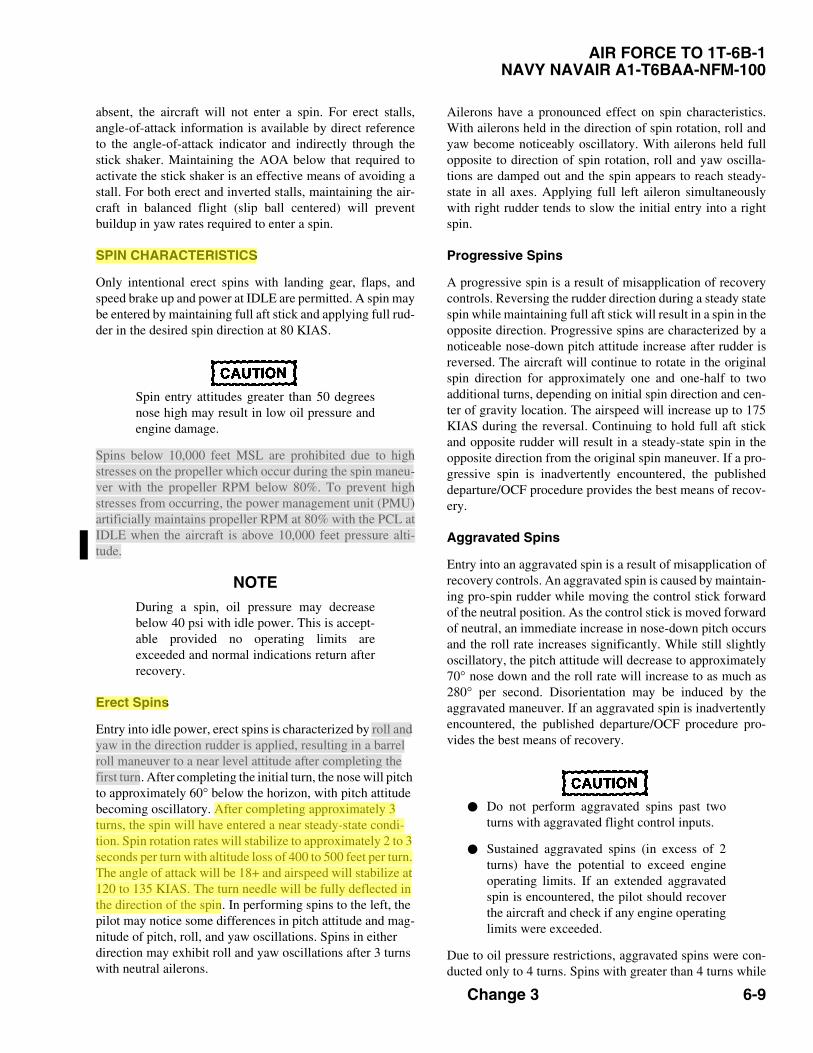
absent, the aircraft will not enter a spin. For erect stalls,angle-of-attack information is available by direct referenceto the angle-of-attack indicator and indirectly through thestick shaker. Maintaining the AOA below that required toactivate the stick shaker is an effective means of avoiding astall. For both erect and inverted stalls, maintaining the air-craft in balanced flight (slip ball centered) will preventbuildup in yaw rates required to enter a spin.
SPIN CHARACTERISTICS
Only intentional erect spins with landing gear, flaps, andspeed brake up and power at IDLE are permitted. A spin maybe entered by maintaining full aft stick and applying full rud-der in the desired spin direction at 80 KIAS.
Spin entry attitudes greater than 50 degreesnose high may result in low oil pressure andengine damage.
Spins below 10,000 feet MSL are prohibited due to highstresses on the propeller which occur during the spin maneu-ver with the propeller RPM below 80%. To prevent highstresses from occurring, the power management unit (PMU)artificially maintains propeller RPM at 80% with the PCL atIDLE when the aircraft is above 10,000 feet pressure alti-tude.
NOTEDuring a spin, oil pressure may decreasebelow 40 psi with idle power. This is accept-able provided no operating limits areexceeded and normal indications return afterrecovery.
Erect Spins
Entry into idle power, erect spins is characterized by roll and yaw in the direction rudder is applied, resulting in a barrel roll maneuver to a near level attitude after completing the first turn. After completing the initial turn, the nose will pitch to approximately 60° below the horizon, with pitch attitude becoming oscillatory. After completing approximately 3 turns, the spin will have entered a near steady-state condi-tion. Spin rotation rates will stabilize to approximately 2 to 3 seconds per turn with altitude loss of 400 to 500 feet per turn. The angle of attack will be 18+ and airspeed will stabilize at 120 to 135 KIAS. The turn needle will be fully deflected in the direction of the spin. In performing spins to the left, the pilot may notice some differences in pitch attitude and mag-nitude of pitch, roll, and yaw oscillations. Spins in either direction may exhibit roll and yaw oscillations after 3 turns with neutral ailerons.
Ailerons have a pronounced effect on spin characteristics.With ailerons held in the direction of spin rotation, roll andyaw become noticeably oscillatory. With ailerons held fullopposite to direction of spin rotation, roll and yaw oscilla-tions are damped out and the spin appears to reach steady-state in all axes. Applying full left aileron simultaneouslywith right rudder tends to slow the initial entry into a rightspin.
Progressive Spins
A progressive spin is a result of misapplication of recoverycontrols. Reversing the rudder direction during a steady statespin while maintaining full aft stick will result in a spin in theopposite direction. Progressive spins are characterized by anoticeable nose-down pitch attitude increase after rudder isreversed. The aircraft will continue to rotate in the originalspin direction for approximately one and one-half to twoadditional turns, depending on initial spin direction and cen-ter of gravity location. The airspeed will increase up to 175KIAS during the reversal. Continuing to hold full aft stickand opposite rudder will result in a steady-state spin in theopposite direction from the original spin maneuver. If a pro-gressive spin is inadvertently encountered, the publisheddeparture/OCF procedure provides the best means of recov-ery.
Aggravated Spins
Entry into an aggravated spin is a result of misapplication ofrecovery controls. An aggravated spin is caused by maintain-ing pro-spin rudder while moving the control stick forwardof the neutral position. As the control stick is moved forwardof neutral, an immediate increase in nose-down pitch occursand the roll rate increases significantly. While still slightlyoscillatory, the pitch attitude will decrease to approximately70° nose down and the roll rate will increase to as much as280° per second. Disorientation may be induced by theaggravated maneuver. If an aggravated spin is inadvertentlyencountered, the published departure/OCF procedure pro-vides the best means of recovery.
• Do not perform aggravated spins past twoturns with aggravated flight control inputs.
• Sustained aggravated spins (in excess of 2turns) have the potential to exceed engineoperating limits. If an extended aggravatedspin is encountered, the pilot should recoverthe aircraft and check if any engine operatinglimits were exceeded.
Due to oil pressure restrictions, aggravated spins were con-ducted only to 4 turns. Spins with greater than 4 turns while

6-10
AIR FORCE 1T-6B-1NAVY (NAVAIR) A1-T6BAA-NFM-100
holding aggravated flight control inputs may cause oil star-vation problems, resulting in damage to the engine. Termi-nation of an aggravated spin after the second turn permitsadequate time to recover the aircraft and avoid oil pressuredrops greater than the engine operating limitations listed inFigure 5-2.
Inverted Departures/Spins
NOTEIntentional inverted departures and spins areprohibited.
Inverted spins have been entered by releasing the controlswith the aircraft in a 60° to 90° pitch attitude at maximumpower (MAX) and an indicated airspeed of 50 knots. Atcontrol release, the aircraft can be expected to torque roll tothe left to a near inverted, nose-level attitude. After slighthesitation, yaw rate will increase as the aircraft enters aright spin, reaching 120° per second after 2 turns are com-pleted. Spins entered using this technique are flatter thanerect spins, with slight pitch oscillations about a mean of30° nose low. Airspeed will read 40 knots and angle ofattack will be pegged at zero during the spin. Normal accel-eration during this spin is typically -1.5 G. These spins havebeen performed with the aircraft loaded at or near the aftcenter of gravity limit. Inverted incipient spins have alsobeen achieved from an inverted stall at maximum power.
In the inverted spins tested, high engine torque is the pri-mary impetus which drives the aircraft into, and sustains,the inverted spin. By reducing the power to IDLE during thefirst 2 spin turns, the pilot can expect the spin to terminatewithout using recovery controls.
Attempts to enter the inverted spin from and inverted stallwith power at IDLE and ailerons neutral typically deterio-rates into an inverted spiral in the direction of applied rud-der, with airspeed rapidly increasing in a steep nose lowattitude.
Configuration Effects
NOTEIntentional spins in other than cruise config-uration at idle power are prohibited.
The effect of power on the erect spin appears to flatten thepitch attitude. At maximum power, the nose rises well abovethe horizon at the completion of the first spin turn. Reducingpower to IDLE causes a noticeable nose-down pitch withthe spin stabilizing as previously described for erect, idlepower spins. Due to engine torque effects, right power-onspins take longer to develop, regardless of aircraft configu-ration, than spins performed to the left. Applying left aile-
ron at the stall will generally prevent the aircraft fromentering a right power-on spin, resulting in a spiral for aslong as full power is maintained.
One turn incipient spins have been performed in power-offand power-on configurations with the speed brake extended.The speed brake position had no noticeable effect on spin orspin recovery characteristics during these spins.
SPIN RECOVERY
During spin recovery, pitch control inputswell forward of neutral may result in a lossof oil pressure and engine damage.
Erect Spin Recovery
Erect spin recovery is prompt after recovery controls areapplied. In all cases, as the control stick is moved forwardand rudder is applied opposite to the direction of turn needledeflection, the pitch attitude will steepen and spin rate willinitially increase. Approximately 50 pounds of push forcewill be required to move the control stick well forward ofthe neutral position. Spin rotation will abruptly cease withthe aircraft in a steep nose-down attitude within one andone-half turns after applying controls. Controls should beneutralized and a smooth pullout initiated to stop the loss ofaltitude and prevent airspeed from building excessively.Expect to lose approximately 500 feet for every turn of aspin with an additional 1500-2000 feet for a normal diverecovery. An erect spin recovery procedure is as follows:
1. Gear, flaps, and speed brake - Retracted
2. PCL - IDLE
3. Rudder - Full opposite to turn needle deflection
4. Control stick - Forward of neutral with ailerons neu-tral
5. Smoothly recover to level flight after spin rotationstops
The aircraft should recover from an erect spin with controls(rudder, ailerons, and elevator) free and with PCL at IDLE.However, the number of additional turns required for spinrotation to cease after releasing controls may increase sig-nificantly. Depending on the center of gravity and howdeeply the aircraft is in the spin, several more turns may berequired for spin recovery following release of the controls.Typically, upon release of controls, the rudder pedals willcenter and the control stick will move to either the left orright of center in the direction of the spin and then slowlybegin to work forward as up-elevator angle decreases. Thecontrols-free spin recovery procedure is not the recom-mended method of recovery.

3-20 Change 3
AIR FORCE TO 1T-6B-1NAVY NAVAIR A1-T6BAA-NFM-100
OBOGS, DEFOG, pressurization, and hydraulic equipment.Consider leaving the engine running while monitoringdescent rate.
Consideration should be given to leaving theengine operating with PCL at mid range.
* 6. PROP SYS circuit breaker - Reset, as required
With the PROP SYS circuit breaker pulledand the PMU switch OFF, the feather dumpsolenoid will not be powered. The propellerwill feather at a slower rate as oil pressuredecreases and the feathering spring takeseffect. Glide performance will be consider-ably reduced and it may not be possible tointercept or fly the emergency landing pat-tern.
* 7. PCL - OFF
* 8. FIREWALL SHUTOFF handle - Pull
* 9. Execute Forced Landing or Eject
COMPRESSOR STALLS
Compressor stalls may be initially identified by abnormalengine noise, increasing ITT, and decreasing N1 and torque,possibly followed by fluctuations in these indications. Audi-ble indications, which may include loud bangs, backfires, orengine sputtering, represent a major difference between astall and an uncommanded power change/loss of power/uncommanded propeller feather, and may aid in diagnosingthe malfunction. Flames and/or smoke may also be visiblefrom the exhaust stacks. Compressor stalls may be caused bydamaged or degraded compressor/turbine blades, disruptedairflow into the engine, or compressor bleed valve malfunc-tions and therefore may occur during either engine accelera-tion or deceleration. Severe compressor stalls may causeengine damage and/or flameout.
* 1. PCL - Slowly retard below stall threshold
* 2. DEFOG switch - ON
NOTESetting the DEFOG switch to ON automati-cally selects high bleed air inflow and willalleviate back pressure on the engine com-pressor.
* 3. PCL - Slowly advance (as required)
IF POWER IS SUFFICIENT FOR CONTINUED FLIGHT:
* 4. PEL - Execute
IF POWER IS INSUFFICIENT TO COMPLETE PEL:
* 5. PCL - OFF
When the engine is so underpowered thathigh rates of descent occur, any delay in shut-ting down the engine to feather the propellormay result in insufficient altitude to reach asuitable landing site.
* 6. FIREWALL SHUTOFF handle - Pull
* 7. Execute Forced Landing or Eject
INADVERTENT DEPARTURE FROM CONTROLLED FLIGHT
It is possible to depart controlled flight as a result ofimproper or overly aggressive control inputs near stall,mechanical failures, atmospheric conditions, or a combina-tion thereof. Power setting has a strong influence on induc-ing or recovering from out of control conditions for theaircraft. Reducing power immediately may allow the aircraftto recover with no other pilot intervention or action. If theout of control condition is allowed to progress, departurecharacteristics can be highly oscillatory and disorienting. Itis crucial the pilot neutralize controls. If an inadvertentdeparture from controlled flight is encountered, accomplishthe following steps, allowing time for the power and controlsto take effect.
* 1. PCL - IDLE
* 2. CONTROLS - NEUTRAL
Improperly positioning the control stick/ele-vator aft of the neutral position may signifi-cantly delay or prevent the aircraft fromrecovering from an OCF/spin which couldresult in loss of aircraft and/or crew.
NOTECycling of control positions or applying anti-spin controls prematurely can aggravate air-craft motion and significantly delay recovery.
* 3. ALTITUDE - CHECK
Recommended minimum altitude for ejectionis 6000 feet AGL.
* 4. Recover from unusual attitude

5 Lakes
12J
Recovery
Altitude: 4,500’ MSL by Five Lakes.
Airspeed: 240 KIAS by Five Lakes.
Angle: Intercept 180° by Five Lakes between a 135° and 225 °, <45° .
Descend to 2,700’ MSL crossing Southern Power Line Slash.
ATIS: @ Southern Power Line Slash switch to Pensacola Approach (CH 6)
with ATIS.
• Conecuh River Bridge to Pt Waldo (RWY 05/14)
- Over the bridge, turn 205° to Pt Nugget.
- Continue 205° until Pt Waldo.
• Conecuh River Bridge to Pt Easy (RWY 23/32)
- Over the bridge, turn 165 ° to intercept HWY 191 north of Munson.
- Fly ¼ WTD west of HWY 191 heading 180°.
- Cross the bend along HWY 191, fly SW ¼ east of HWY 191 to Pt Easy.
SLOW DOWN TO 200 KIAS WHEN CROSSING WALDO OR EASY.
UPON REACHING 200 KIAS BEGIN DESCENT TO 1,300’ MSL.
VFR Course Rules Arrivals – North Recovery to Conecuh River Bridge
12
180°
18
0°
Conecuh River Bridge
Munson (HWY191)
Pt Waldo Pt Easy
Pt Nugget
Pt Jay
Paper mill
5 Lakes
4,500’
MSL
4,500’
MSL
2,700’ MSL 2,700’ MSL
Recovery
Altitude: 4,500’ MSL by Five Lakes.
Airspeed: 240 KIAS by Five Lakes.
Angle: Intercept 180° by Five Lakes between a 135° and 225 °, <45° .
Descend to 2,700’ MSL crossing Southern Power Line Slash.
ATIS: @ Southern Power Line Slash switch to Pensacola Approach (CH 6)
with ATIS.
• Conecuh River Bridge to Pt Waldo (RWY 05/14)
- Over the bridge, turn 205° to Pt Nugget.
- Continue 205° until Pt Waldo.
• Conecuh River Bridge to Pt Easy (RWY 23/32)
- Over the bridge, turn 165 ° to intercept HWY 191 north of Munson.
- Fly ¼ WTD west of HWY 191 heading 180°.
- Cross the bend along HWY 191, fly SW ¼ east of HWY 191 to Pt Easy.
SLOW DOWN TO 200 KIAS WHEN CROSSING WALDO OR EASY.
UPON REACHING 200 KIAS BEGIN DESCENT TO 1,300’ MSL.
VFR Course Rules Arrivals – North Recovery to Conecuh River Bridge
12
180°
18
0°
Conecuh River Bridge
Munson (HWY191)
ALT: 4,500’ MSL
*Begin descent to 2700’ MSL @
southern powerline slash
A/S: 240 KIAS
ANGLE: < 45° (135°-225°)
ATIS: CH 1
Pt Waldo Pt Easy
Pt Nugget
Pt Jay
Paper mill
12J
ALT: 4,500’ MSL
*Begin descent to 2700’ MSL @
southern powerline slash
A/S: 240 KIAS
ANGLE: < 45° (135°-225°)
ATIS: CH 1
Powerline Slash Powerline Slash
COMTRAWINGFIVEINST 3710.3 COMTRAWINGFIVEINST 3710.3
*Chart not to scale. *Chart not to scale.
OCTOBER 2015 OCTOBER 2015

VFR Course Rules Arrivals – North Recovery To Point Jay
Recovery
Altitude: 4,500’ MSL when intercepting Hwy 113.
Airspeed: 240 KIAS.
Angle: <45° intercept.
ATIS: Contact Pensacola Approach (CH 6) prior to Pt Jay with ATIS.
• “T” Intersection to Pt Jay:
- Turn 130° to Pt Jay and descend to 2,200’ MSL.
• Pt Jay to Pt Waldo (RWY 05/14)
- Turn 160° to Pt Waldo.
• Pt Jay to Pt Easy (RWY 23/32)
- Turn 115° to Pt Nugget.
- At Pt Nugget, turn 145° to Pt Easy.
SLOW DOWN TO 200 KIAS WHEN CROSSING WALDO OR EASY.
UPON REACHING 200 KIAS BEGIN DESCENT TO 1,300’ MSL.
13
Pt Easy
Pt Nugget
“T” Intersection
Pt Jay
Pt Waldo
Papermill
ALT: 4,500’ MSL
*begin descent to 2200’ MSL @ T Int.
A/S: 240 KIAS
ANGLE: < 45° (135°-225°)
ATIS: CH 1
ALT: 4,500’ MSL
*begin descent to 2200’ MSL @ T Int.
A/S: 240 KIAS
ANGLE: < 45° (135°-225°)
ATIS: CH 1
VFR Course Rules Arrivals – North Recovery To Point Jay
Recovery
Altitude: 4,500’ MSL when intercepting Hwy 113.
Airspeed: 240 KIAS.
Angle: <45° intercept.
ATIS: Contact Pensacola Approach (CH 6) prior to Pt Jay with ATIS.
• “T” Intersection to Pt Jay:
- Turn 130° to Pt Jay and descend to 2,200’ MSL.
• Pt Jay to Pt Waldo (RWY 05/14)
- Turn 160° to Pt Waldo.
• Pt Jay to Pt Easy (RWY 23/32)
- Turn 115° to Pt Nugget.
- At Pt Nugget, turn 145° to Pt Easy.
SLOW DOWN TO 200 KIAS WHEN CROSSING WALDO OR EASY.
UPON REACHING 200 KIAS BEGIN DESCENT TO 1,300’ MSL.
13
Pt Easy
Pt Nugget
“T” Intersection
Pt Jay
Pt Waldo
Papermill
COMTRAWINGFIVEINST 3710.3 COMTRAWINGFIVEINST 3710.3
4,500’ MSL 4,500’ MSL
*Chart not to scale. *Chart not to scale.
HWY 31 HWY 31
HW
Y 1
13
HW
Y 1
13
OCTOBER 2015 OCTOBER 2015

Pt Easy
VFR Course Rules Arrivals – Area 1
Recovery
• Area 1 to Chumuckla
- Intercept Chicken Ranch between a 015° and 105° course, 3,500’ MSL.
Avoid Summerdale (KNFD) below 5,000’ MSL and 3 nm.
Antennas up to 2,047’ MSL located south of I-10.
MEF at Chicken Ranch: 2,200’ MSL.
Elsanor Airport: 122.9
- Abeam Chicken Ranch, contact Pensacola Approach (CH 6) with ATIS and
turn 060° to HWY 29.
- At HWY 29, turn 360° and follow HWY 29 north to Molino (triangle of trees).
- At Molino, turn 065° to Chumuckla, on heading descend to 1,700’ MSL.
MEF at Molino: 1,700’ MSL.
• Chumuckla to Pt Waldo (RWY 05/14)
- Fly east, ¼ wingtip north of HWY 182 to Pt Waldo.
• Chumuckla to Pt Easy (RWY 23/32)
- Turn 055° towards Pt Nugget.
- At Pt Nugget, turn 145° to Pt Easy.
SLOW DOWN TO 200 KIAS WHEN CROSSING WALDO OR EASY.
UPON REACHING 200 KIAS BEGIN DESCENT TO 1,300’ MSL.
Pt Nugget
Pt Waldo
HWY 29
Molino
(descend)
Chumuckla
HWY 182
Chicken
Ranch
ALT: 3,500’ MSL
ANGLE < 45° (015°/105°)
A/S: 240 KIAS
ATIS: CH 1
*Obstacles for reference only.
11
1549’ MSL 2047’ MSL
VFR Course Rules Arrivals – Area 1
Recovery
• Area 1 to Chumuckla
- Intercept Chicken Ranch between a 015° and 105° course, 3,500’ MSL.
Avoid Summerdale (KNFD) below 5,000’ MSL and 3 nm.
Antennas up to 2,047’ MSL located south of I-10.
MEF at Chicken Ranch: 2,200’ MSL.
Elsanor Airport: 122.9
- Abeam Chicken Ranch, contact Pensacola Approach (CH 6) with ATIS and
turn 060° to HWY 29.
- At HWY 29, turn 360° and follow HWY 29 north to Molino (triangle of trees).
- At Molino, turn 065° to Chumuckla, on heading descend to 1,700’ MSL.
MEF at Molino: 1,700’ MSL.
• Chumuckla to Pt Waldo (RWY 05/14)
- Fly east, ¼ wingtip north of HWY 182 to Pt Waldo.
• Chumuckla to Pt Easy (RWY 23/32)
- Turn 055° towards Pt Nugget.
- At Pt Nugget, turn 145° to Pt Easy.
SLOW DOWN TO 200 KIAS WHEN CROSSING WALDO OR EASY.
UPON REACHING 200 KIAS BEGIN DESCENT TO 1,300’ MSL.
11
COMTRAWINGFIVEINST 3710.3 COMTRAWINGFIVEINST 3710.3
KNFD
KNSE
ALT: 3,500’ MSL
ANGLE: < 45° (015°/105°)
A/S: 240 KIAS
ATIS: CH 1
*Obstacles for reference only.
KNFD
KNSE
Chicken
Ranch
2047’ MSL
1549’ MSL
HWY 29
Molino
(descend)
Chumuckla
HWY 182 Pt Waldo Pt Easy
Pt Nugget
*Chart not to scale. *Chart not to scale.
OCTOBER 2015 OCTOBER 2015
HWY 90
HWY 90
3,500’
MSL
3,500’
MSL
HW
Y 5
9
HW
Y 5
9

North Whiting Pattern Operations RWY 5/14
All TW5 aircraft
Discontinued Entry
ALL AIRCRAFT:
- Contact North Tower at Pt Waldo.
- Inside Pt Waldo, break airspeed.
- Descend to 1,300’ MSL once slowed to 200 KIAS.
RWY 14
- Line up between tower and RWY 14.
- Break away from tower.
RWY 05
- Proceed south along HWY 89 until the second bend (turn south again).
- Turn to remain north of the third bend (turns east again).
- Remain north of Langley Road.
- Break away from tower.
DISCONTINUED ENTRY
- Turn to heading of 010°.
- Climb to 2700’ MSL and contact Pensacola Approach.
- Reenter pattern at Pt Waldo via direct or radar vectors.
WAVEOFF
- Climb to pattern alt 1,000’ MSL.
- Request downwind, follow tower instructions.
Pt Waldo
16
Break Alt: 1300’ MSL
Pattern Alt: 1000’ MSL
Airspeed: 200 KIAS
North Whiting Pattern Operations RWY 5/14
All TW5 aircraft
Discontinued Entry
Pt Waldo
16
Break Alt: 1500’ MSL
Pattern Alt: 1000’ MSL
Airspeed: 200 KIAS
ALL AIRCRAFT:
- Contact North Tower at Pt Waldo.
- Inside Pt Waldo, break airspeed.
- Descend to 1,300’ MSL once slowed to 200 KIAS.
RWY 14
- Line up between tower and RWY 14.
- Break away from tower.
RWY 05
- Proceed south along HWY 89 until the second bend (turn south again).
- Turn to remain north of the third bend (turns east again).
- Remain north of Langley Road.
- Break away from tower.
DISCONTINUED ENTRY
- Turn to heading of 010°.
- Climb to 2700’ MSL and contact Pensacola Approach.
- Reenter pattern at Pt Waldo via direct or radar vectors.
WAVEOFF
- Climb to pattern alt 1,000’ MSL.
- Request downwind, follow tower instructions.
HOMEFIELD DELTA PATTERN
CONFIGURATION Gear Down Flaps Up
ALTITUDE 2,500’ MSL
AIRSPEED 120 KIAS
HOMEFIELD DELTA PATTERN
CONFIGURATION Gear Down Flaps Up
ALTITUDE 2,500’ MSL
AIRSPEED 120 KIAS
COMTRAWINGFIVEINST 3710.3 COMTRAWINGFIVEINST 3710.3 OCTOBER 2015 OCTOBER 2015
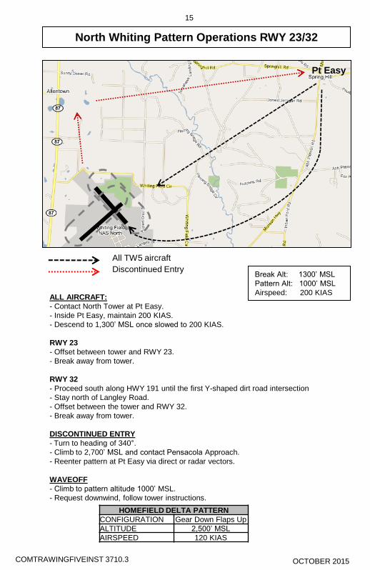
North Whiting Pattern Operations RWY 23/32
Pt Easy
All TW5 aircraft
Discontinued Entry
15
Break Alt: 1300’ MSL
Pattern Alt: 1000’ MSL
Airspeed: 200 KIAS
HOMEFIELD DELTA PATTERN
CONFIGURATION Gear Down Flaps Up
ALTITUDE 2,500’ MSL
AIRSPEED 120 KIAS
North Whiting Pattern Operations RWY 23/32
Pt Easy
All TW5 aircraft
Discontinued Entry
15
ALL AIRCRAFT:
- Contact North Tower at Pt Easy.
- Inside Pt Easy, maintain 200 KIAS.
- Descend to 1,300’ MSL once slowed to 200 KIAS.
RWY 23
- Offset between tower and RWY 23.
- Break away from tower.
RWY 32
- Proceed south along HWY 191 until the first Y-shaped dirt road intersection.
- Stay north of Langley Road.
- Offset between the tower and RWY 32.
- Break away from tower.
DISCONTINUED ENTRY
- Turn to heading of 340°.
- Climb to 2,700’ MSL and contact Pensacola Approach.
- Reenter pattern at Pt Easy via direct or radar vectors.
WAVEOFF
- Climb to pattern altitude 1000’ MSL.
- Request downwind, follow tower instructions.
Break Alt: 1300’ MSL
Pattern Alt: 1000’ MSL
Airspeed: 200 KIAS ALL AIRCRAFT:
- Contact North Tower at Pt Easy.
- Inside Pt Easy, maintain 200 KIAS.
- Descend to 1,300’ MSL once slowed to 200 KIAS.
RWY 23
- Offset between tower and RWY 23.
- Break away from tower.
RWY 32
- Proceed south along HWY 191 until the first Y-shaped dirt road intersection
- Stay north of Langley Road.
- Offset between the tower and RWY 32.
- Break away from tower.
DISCONTINUED ENTRY
- Turn to heading of 340°.
- Climb to 2,700’ MSL and contact Pensacola Approach.
- Reenter pattern at Pt Easy via direct or radar vectors.
WAVEOFF
- Climb to pattern altitude 1000’ MSL.
- Request downwind, follow tower instructions.
HOMEFIELD DELTA PATTERN
CONFIGURATION Gear Down Flaps Up
ALTITUDE 2,500’ MSL
AIRSPEED 120 KIAS
COMTRAWINGFIVEINST 3710.3 COMTRAWINGFIVEINST 3710.3 OCTOBER 2015 OCTOBER 2015

Ejection Seat Sequencing Mitigation Contingencies
• FCP Incapacitation1. ISS Mode Selector – BOTH2. RCP – Eject
• ICS Failure• “Face curtain” signal serves as the prepatory command
during a controlled ejection. A thumbs up from eachoccupant is required to initiate ejection sequence.
• FCP shall initiate ejection sequence with three “raps” ofthe canopy
• RCP occupant shall initiate ejection ON third “rap”• FCP occupant shall initiate ejection NET ~0.5 seconds
AFTER third “rap”
Misc • Unqualified personnel prohibited
• Must be NATOPS qualified, enrolled in a formal aviation syllabus, or an observer qualified Naval Flight Officer, Flight Surgeon, or AeromedicalSafety Officer
• Delaying ejection below 2,000 ft AGL is notrecommended
• Any delays may negatively impact theejection envelope
• FCP occupant initiates ejection NET ~0.5 secAFTER third “EJECT” call or immediately afterconfirming the RCP occupant has ejected
• Proper manual ejection sequencing requiresthe RCP occupant to eject prior to the FCPoccupant
CRM • RCP Delaying Ejection
• May lead to collision with FCP seat• RCP shall not hesitate or delay ejecting• RCP occupant shall initiate ejection ON third “EJECT” call
• FCP Initiating Ejection Too Soon• May lead to collision with RCP seat• FCP shall initiate ejection NET ~0.5 sec after third
“EJECT” call
Procedures • Dual Flights
• ISS Mode Selector – SOLO in flight (Before Takeoff checks)• RCP occupant shall initiate ejection ON third “EJECT” call• FCP occupant shall initiate ejection NET ~0.5 sec AFTER
third “EJECT” call
• Solo Flights• Normal NATOPS Procedures Apply• Ensure ISS Mode Selector is in SOLO