Embed Size (px)
Citation preview
TE Computer-Computer Network- Paper solution for End Sem 70 marks exam 2015-16
Prof. B.A.Khivsara-SNJB’s COE, Chandwad
Q1) What is FTP? What are the three FTP transmission modes?[4]
Ans: The File Transfer Protocol (FTP) is a standard network protocol used to transfer
computer files between a client and server on a computer network.FTP is built on a client-
server model architecture and uses separate control and data connections between the client
and the server. FTP users may authenticate themselves with a clear-text sign-in protocol,
normally in the form of a username and password, but can connect anonymously if the server
is configured to allow it. For secure transmission that protects the username and password,
and encrypts the content, FTP is often secured with SSL/TLS (FTPS)
Data transfer can be done in any of three modes:
Stream mode: Data is sent as a continuous stream, relieving FTP from doing any
processing. Rather, all processing is left up to TCP. No End-of-file indicator is needed,
unless the data is divided into records.
Block mode: FTP breaks the data into several blocks (block header, byte count, and data
field) and then passes it on to TCP.
Compressed mode: Data is compressed using a simple algorithm (usually run-length
encoding).
Q2)Explain UDP header?The following is a DUMP of a UDP header in hexadecimal
format. 06 32 00 0D 00 1C E2 17. [8]
i. What is source port number?
ii. What is destination port number?
iii. What is length of user datagram?
iv. What is length of the data?
v. Is the packet directed from a client to server or vice versa?
vi. What is the client process?
Ans: The UDP header consists of four fields each of 2 bytes in length:
Source Port (UDP packets from a client use this as a service access point (SAP) to
indicate the session on the local client that originated the packet. UDP packets from a
server carry the server SAP in this field)
Destination Port (UDP packets from a client use this as a service access point (SAP) to
indicate the service required from the remote server. UDP packets from a server carry
the client SAP in this field)
UDP length (The number of bytes comprising the combined UDP header information
and payload data)
UDP Checksum (A checksum to verify that the end to end data has not been corrupted
by routers or bridges in the network or by the processing in an end system. The
algorithm to compute the checksum is the Standard Internet Checksum algorithm. This
allows the receiver to verify that it was the intended destination of the packet, because
it covers the IP addresses, port numbers and protocol number, and it verifies that the
TE Computer-Computer Network- Paper solution for End Sem 70 marks exam 2015-16
Prof. B.A.Khivsara-SNJB’s COE, Chandwad
packet is not truncated or padded, because it covers the size field. Therefore, this
protects an application against receiving corrupted payload data in place of, or in
addition to, the data that was sent. In the cases where this check is not required, the
value of 0x0000 is placed in this field, in which case the data is not checked by th e
receiver.
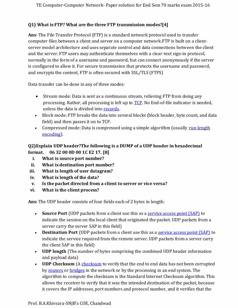
Figure: UDP Header
a. The source port number is the first four hexadecimal digits (0632)
or 1586
b. The destination port number is the second four hexadecimal digits (000D)
or 13.
c. The third four hexadecimal digits (001C)16 define the length of the whole UDP packet as 28
bytes.
d. The length of the data is the length of the whole packet minus the length of the header, or 28
- 8 = 20 bytes.
e. Since the destination port number is 13 (well-known port), the packet is from the client to
the server.
f. The client process is the Daytime .
Q 1 C) What is fragmentation in IPV4, Explain with example? An IPV4 datagram arrives with
fragmentation offset of 0 and an Mbit of 0 , Is this a first fragment, middle fragment or last
fragment?[4]
Ans: The Internet Protocol (IP) implements datagram fragmentation, breaking it into smaller
pieces, so that packets may be formed that can pass through a link with a smaller maximum
transmission unit (MTU) than the original datagram size.
To give you an example of a fragmentation let's consider the following two networks:
Network A Network B
MTU 1500 MTU1400
Router
Host A----****-----/==/----*---***----Host B
-----> --> -->
Packet 1 Packet
Host A resides on Network A, which has a MTU of 1500. Host B on the other side is part of
Network B where the MTU there is 1400.
TE Computer-Computer Network- Paper solution for End Sem 70 marks exam 2015-16
Prof. B.A.Khivsara-SNJB’s COE, Chandwad
Host A generates a packet (****) with a size of 1500 bytes which is equal to the network's MTU
(1500). When the packet transits the router that connects the networks, the router knows that
Network B's MTU is 1400 bytes, so it needs to split the 1500 byte packet into two smaller
packets and transmit them on the network, so it creates the first packet which is 1400 bytes
long (***) and then sticks the rest of the original packet into the second packet(*) which is just
100 bytes.
When Host B receives the packets, it will realize it needs to assemble the two packets in order
to retrieve their data, and that's exactly what happens.
If the M bit is 0, it means that there are no more fragments; the fragment is the last one.
Since the offset is zero, it cannot be the last fragment of a fragmented datagram. The datagram
is not fragmented.
Q1 d) What is difference between open-loop and closed-loop congestion control. Name
the policies that can prevent congestion? [4]
Ans:
Open Loop Congestion Control
• In this method, policies are used to prevent the congestion before it happens.
• Congestion control is handled either by the source or by the destination.
• The various methods used for open loop congestion control are:
1. Retransmission Policy
2. Window Policy
3. Acknowledgement Policy
4. Discarding Policy
5. Admission Policy
Closed Loop Congestion Control
• Closed loop congestion control mechanisms try to remove the congestion after it ha ppens.
• The various methods used for closed loop congestion control are:
1. Backpressure
2. Choke Packet
3. Implicit Signaling
4. Explicit Signaling
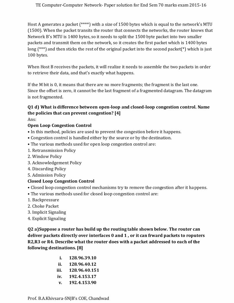
Q2 a)Suppose a router has build up the routing table shown below. The router can
deliver packets directly over interfaces 0 and 1 , or it can frward packets to roputers
R2,R3 or R4. Describe what the router does with a packet addressed to each of the
following destinations. [8]
i. 128.96.39.10
ii. 128.96.40.12
iii. 128.96.40.151
iv. 192.4.153.17
v. 192.4.153.90
TE Computer-Computer Network- Paper solution for End Sem 70 marks exam 2015-16
Prof. B.A.Khivsara-SNJB’s COE, Chandwad
Routing Table
Ans:
i. 128.96.39.10-Applying the subnet mask 255.255.255.128, we get 128.96.39.0. Use the
interface 0 as the next hop.
ii. 128.96.40.12-Applying the subnet mask 255.255.255.128, we get 128.96.40.0 (next hop
is Router R2)
iii. 128.96.40.151- Applying all the subnet mask give 128.96.40.128, None of the subnet
number entries match, hence use default Router R4.
iv. 192.4.153.17-Applying subnet mask 255.255.255.192, we get 192.4.153.0. Use Router
R3 as next hop.
v. 192.4.153.90- None of the subnet number entries match, hence use default Router R4
next hop.
Q2 b) What are the 4 general techniques to improve quality of service?Expalin any one
in detail?[6]
Ans: The 4 general techniques to improve quality of service are:
Traffice Shaping
Scheduling
Admission control
Resource reservation
Scheduling [1]
Packets from different flows arrive at a switch or router for processing. A good scheduling
technique treats the different flows in a fair and appropriate manner. Several scheduling
techniques are designed to improve the quality of service. We discuss three of them here: 1~'
tO queuing, priority queuing, and weighted fair queuing.
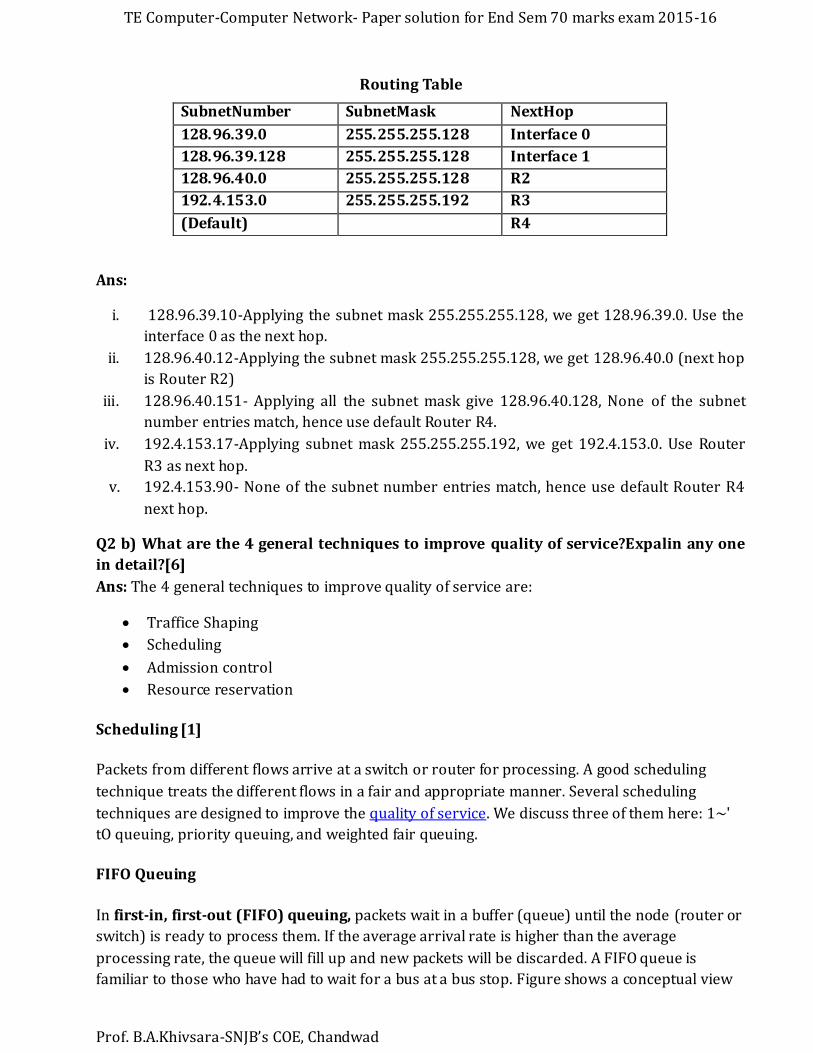
FIFO Queuing
In first-in, first-out (FIFO) queuing, packets wait in a buffer (queue) until the node (router or
switch) is ready to process them. If the average arrival rate is higher than the average
processing rate, the queue will fill up and new packets will be discarded. A FIFO queue is
familiar to those who have had to wait for a bus at a bus stop. Figure shows a conceptual view
SubnetNumber SubnetMask NextHop
128.96.39.0 255.255.255.128 Interface 0
128.96.39.128 255.255.255.128 Interface 1
128.96.40.0 255.255.255.128 R2
192.4.153.0 255.255.255.192 R3
(Default) R4
TE Computer-Computer Network- Paper solution for End Sem 70 marks exam 2015-16
Prof. B.A.Khivsara-SNJB’s COE, Chandwad
of a FIFO queue.
Figure2.1: FIFO queue
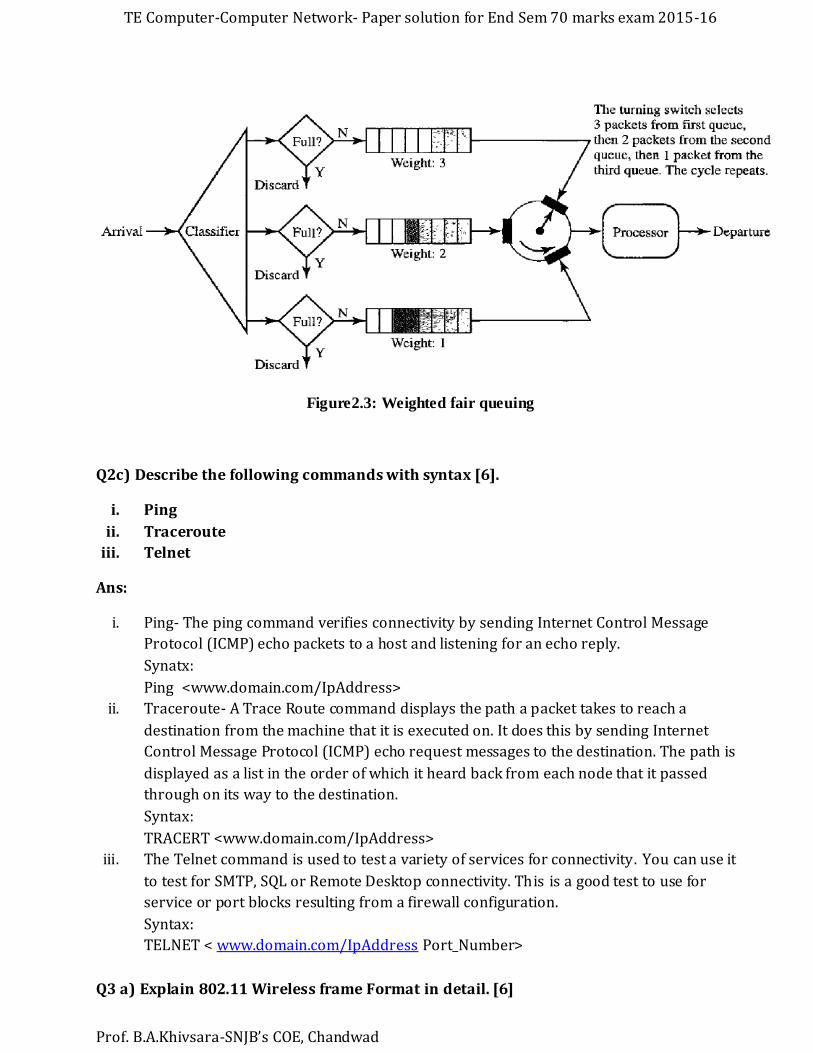
Priority Queuing
In priority queuing, packets are first assigned to a priority class. Each priority class has its own
queue. The packets in the highest-priority queue are processed first. Packets in the lowest-
priority queue are processed last. Note that the system does not stop serving a queue until it is
empty. Figure shows priority queuing with two priority levels (for simplicity).
Figure2.2: Priority queuing
A priority queue can provide better QoS than the FIFO queue because higher-priority traffic, such as multimedia, can reach the destination with less delay. However, there is a potential drawback. If there is a continuous flow in a high-priority queue, the packets in the lower-priority queues will
never have a chance to be processed. This is a condition called starvation.
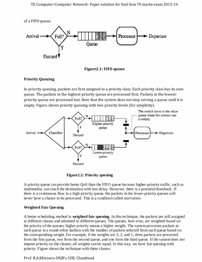
Weighted Fair Queuing
A better scheduling method is weighted fair queuing. In this technique, the packets are still assigned to different classes and admitted to different queues. The queues, how-ever, are weighted based on
the priority of the queues; higher priority means a higher weight. The system processes packets in each queue in a round-robin fashion with the number of packets selected from each queue based on the corresponding weight. For example, if the weights are 3, 2, and 1, three packets are processed
from the first queue, two from the second queue, and one from the third queue. If the system does not impose priority on the classes, all weights can be equal. In this way, we have fair queuing with
priority. Figure shows the technique with three classes.
TE Computer-Computer Network- Paper solution for End Sem 70 marks exam 2015-16
Prof. B.A.Khivsara-SNJB’s COE, Chandwad
Figure2.3: Weighted fair queuing
Q2c) Describe the following commands with syntax [6].
i. Ping
ii. Traceroute
iii. Telnet
Ans:
i. Ping- The ping command verifies connectivity by sending Internet Control Message
Protocol (ICMP) echo packets to a host and listening for an echo reply.
Synatx:
Ping <www.domain.com/IpAddress>
ii. Traceroute- A Trace Route command displays the path a packet takes to reach a
destination from the machine that it is executed on. It does this by sending Internet
Control Message Protocol (ICMP) echo request messages to the destination. The path is
displayed as a list in the order of which it heard back from each node that it passed
through on its way to the destination.
Syntax:
TRACERT <www.domain.com/IpAddress>
iii. The Telnet command is used to test a variety of services for connectivity. You can use it
to test for SMTP, SQL or Remote Desktop connectivity. This is a good test to use for
service or port blocks resulting from a firewall configuration.
Syntax:
TELNET < www.domain.com/IpAddress Port_Number>
Q3 a) Explain 802.11 Wireless frame Format in detail. [6]
TE Computer-Computer Network- Paper solution for End Sem 70 marks exam 2015-16
Prof. B.A.Khivsara-SNJB’s COE, Chandwad
Ans:
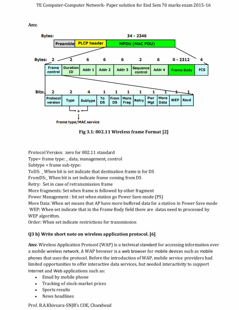
Fig 3.1: 802.11 Wireless frame Format [2]
Protocol Version: zero for 802.11 standard
Type= frame type: _ data, management, control
Subtype = frame sub-type:
ToDS: _ When bit is set indicate that destination frame is for DS
FromDS:_ When bit is set indicate frame coming from DS
Retry: Set in case of retransmission frame
More fragments: Set when frame is followed by other fragment
Power Management : bit set when station go Power Save mode (PS)
More Data: When set means that AP have more buffered data for a station in Power Save mode
WEP: When set indicate that in the Frame Body field there are datas need to processed by
WEP algorithm.
Order: When set indicate restrictions for transmission
Q3 b) Write short note on wireless application protocol. [6]
Ans: Wireless Application Protocol (WAP) is a technical standard for accessing information over
a mobile wireless network. A WAP browser is a web browser for mobile devices such as mobile
phones that uses the protocol. Before the introduction of WAP, mobile service providers had
limited opportunities to offer interactive data services, but needed interactivity to support
Internet and Web applications such as:
Email by mobile phone
Tracking of stock-market prices
Sports results
News headlines
TE Computer-Computer Network- Paper solution for End Sem 70 marks exam 2015-16
Prof. B.A.Khivsara-SNJB’s COE, Chandwad
Music downloads
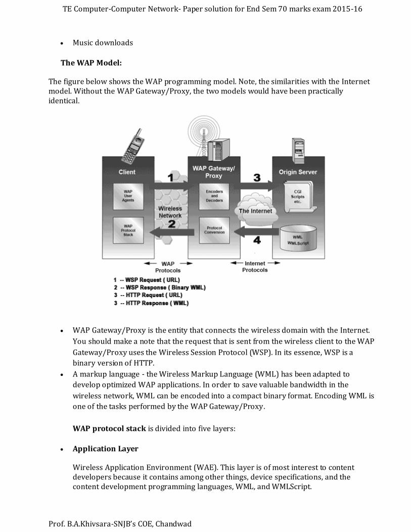
The WAP Model:
The figure below shows the WAP programming model. Note, the similarities with the Internet model. Without the WAP Gateway/Proxy, the two models would have been practically identical.
WAP Gateway/Proxy is the entity that connects the wireless domain with the Internet.
You should make a note that the request that is sent from the wireless client to the WAP
Gateway/Proxy uses the Wireless Session Protocol (WSP). In its essence, WSP is a
binary version of HTTP.
A markup language - the Wireless Markup Language (WML) has been adapted to
develop optimized WAP applications. In order to save valuable bandwidth in the
wireless network, WML can be encoded into a compact binary format. Encoding WML is
one of the tasks performed by the WAP Gateway/Proxy.
WAP protocol stack is divided into five layers:
Application Layer
Wireless Application Environment (WAE). This layer is of most interest to content developers because it contains among other things, device specifications, and the content development programming languages, WML, and WMLScript.

TE Computer-Computer Network- Paper solution for End Sem 70 marks exam 2015-16
Prof. B.A.Khivsara-SNJB’s COE, Chandwad
Session Layer Wireless Session Protocol (WSP). Unlike HTTP, WSP has been designed by the WAP Forum to provide fast connection suspension and reconnection.
Transaction Layer Wireless Transaction Protocol (WTP). The WTP runs on top of a datagram service, such as User Datagram Protocol (UDP) and is part of the standard suite of TCP/IP protocols used to provide a simplified protocol suitable for low bandwidth wireless stations.
Security Layer Wireless Transport Layer Security (WTLS). WTLS incorporates security features that are based upon the established Transport Layer Security (TLS) protocol standard. It includes data integrity checks, privacy, service denial, and authentication services.
Transport Layer Wireless Datagram Protocol (WDP). The WDP allows WAP to be bearer-independent by adapting the transport layer of the underlying bearer. The WDP presents a consistent data format to the higher layers of the WAP protocol stack, thereby offering the advantage of bearer independence to application developers.
Q3 c) What is the purpose of NAV. Explain?
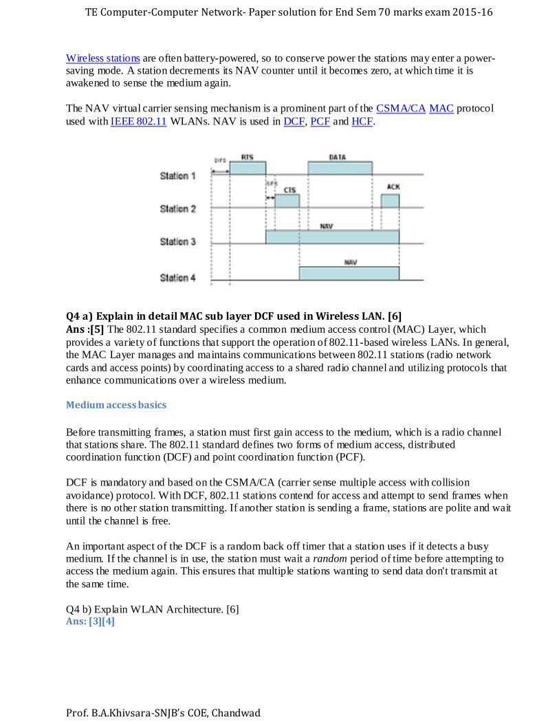
Ans: The network allocation vector (NAV) is a virtual carrier-sensing mechanism used with
wireless network protocols such as IEEE 802.11 and IEEE 802.16 (WiMax). The virtual carrier sensing is a logical abstraction which limits the need for physical carrier-sensing at the air interface
in order to save power. The MAC layer frame headers contain a duration field that specifies the transmission time required for the frame, in which time the medium will be busy. The stations listening on the wireless medium read the Duration field and set their NAV, which is an indicator for
a station on how long it must defer from accessing the medium.
The NAV may be thought of as a counter, which counts down to zero at a uniform rate. When the counter is zero, the virtual CS indication is that the medium is idle; when nonzero, the indication is
busy. The medium shall be determined to be busy when the STA is transmitting. In IEEE 802.11, the NAV represents the number of microseconds the sending STA intends to hold the medium busy (maximum of 32,767 microseconds).
TE Computer-Computer Network- Paper solution for End Sem 70 marks exam 2015-16
Prof. B.A.Khivsara-SNJB’s COE, Chandwad
Wireless stations are often battery-powered, so to conserve power the stations may enter a power-saving mode. A station decrements its NAV counter until it becomes zero, at which time it is awakened to sense the medium again.
The NAV virtual carrier sensing mechanism is a prominent part of the CSMA/CA MAC protocol
used with IEEE 802.11 WLANs. NAV is used in DCF, PCF and HCF.
Q4 a) Explain in detail MAC sub layer DCF used in Wireless LAN. [6] Ans :[5] The 802.11 standard specifies a common medium access control (MAC) Layer, which
provides a variety of functions that support the operation of 802.11-based wireless LANs. In general, the MAC Layer manages and maintains communications between 802.11 stations (radio network
cards and access points) by coordinating access to a shared radio channel and utilizing protocols that enhance communications over a wireless medium.
Medium access basics
Before transmitting frames, a station must first gain access to the medium, which is a radio channel that stations share. The 802.11 standard defines two forms of medium access, distributed coordination function (DCF) and point coordination function (PCF).
DCF is mandatory and based on the CSMA/CA (carrier sense multiple access with collision
avoidance) protocol. With DCF, 802.11 stations contend for access and attempt to send frames when there is no other station transmitting. If another station is sending a frame, stations are polite and wait
until the channel is free.
An important aspect of the DCF is a random back off timer that a station uses if it detects a busy medium. If the channel is in use, the station must wait a random period of time before attempting to access the medium again. This ensures that multiple stations wanting to send data don't transmit at
the same time.
Q4 b) Explain WLAN Architecture. [6] Ans: [3][4]
TE Computer-Computer Network- Paper solution for End Sem 70 marks exam 2015-16
Prof. B.A.Khivsara-SNJB’s COE, Chandwad
Stations
All components that can connect into a wireless medium in a network are referred to as
stations (STA). All stations are equipped with wireless network interface controllers (WNICs).
Wireless stations fall into one of two categories: wireless access points, and clients. Access
points (APs), normally wireless routers, are base stations for the wireless network. They
transmit and receive radio frequencies for wireless enabled devices to communicate with.
Wireless clients can be mobile devices such as laptops, personal digital assistants, IP phones
and other smartphones, or fixed devices such as desktops and workstations that are equipped
with a wireless network interface.
Basic service set
The basic service set (BSS) is a set of all stations that can communicate with each other at PHY
layer. Every BSS has an identification (ID) called the BSSID, which is the MAC address of the
access point servicing the BSS.
There are two types of BSS: Independent BSS (also referred to as IBSS), and infrastructure BSS.
An independent BSS (IBSS) is an ad hoc network that contains no access points, which means
they can not connect to any other basic service set.
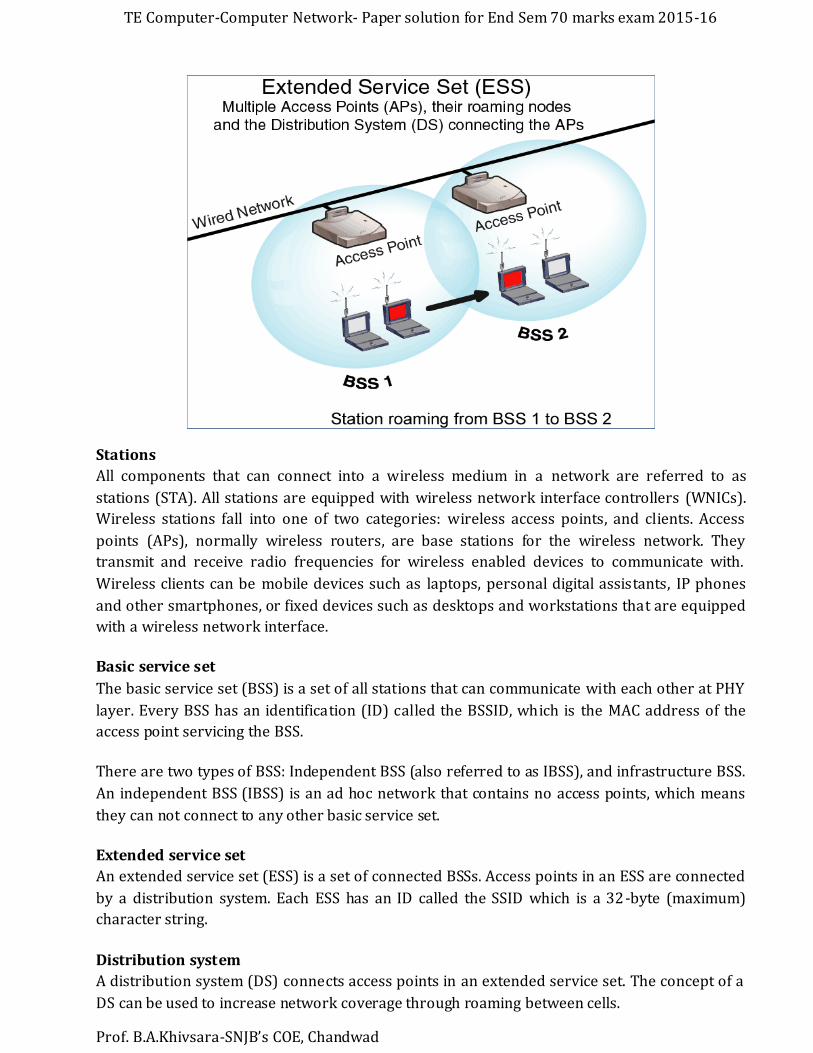
Extended service set
An extended service set (ESS) is a set of connected BSSs. Access points in an ESS are connected
by a distribution system. Each ESS has an ID called the SSID which is a 32-byte (maximum)
character string.
Distribution system
A distribution system (DS) connects access points in an extended service set. The concept of a
DS can be used to increase network coverage through roaming between cells.

TE Computer-Computer Network- Paper solution for End Sem 70 marks exam 2015-16
Prof. B.A.Khivsara-SNJB’s COE, Chandwad
DS can be wired or wireless. Current wireless distribution systems are mostly based on WDS or
MESH protocols, though other systems are in use.
Q4 c) Explain bluetooth frame format.[4] Ans:[6][7]
1. Access Code: It is 72 bit field that contains synchronization bits. It identifies the master.
2. Header: This is 54-bit field. It contain 18 bit pattern that is repeated for 3 time.
The header field contains following subfields:
(i) Address: This 3 bit field can define upto seven slaves (1 to 7). If the address is zero, it is used for broadcast communication from primary to all secondaries.
(ii)Type: This 4 bit field identifies the type of data coming from upper layers.
(iii) F: This flow bit is used for flow control. When set to 1, it means the device is unable to receive more frames.
(iv) A: This bit is used for acknowledgement.
(v) S: This bit contains a sequence number of the frame to detect retransmission. As stop and wait protocol is used, one bit is sufficient.
(vi) Checksum: This 8 bit field contains checksum to detect errors in header.
3. Data: This field can be 0 to 2744 bits long. It contains data or control information coming from upper layers
Q5 a) What is VOIP? Explain different layers of DTN? [8]
Ans:
Voice over IP (VoIP) is a methodology and group of technologies for the delivery of voice
communications and multimedia sessions over Internet Protocol (IP) networks, such as the
Internet. Other terms commonly associated with VoIP are IP telephony, Internet telephony,
broadband telephony, and broadband phone service.[8]
TE Computer-Computer Network- Paper solution for End Sem 70 marks exam 2015-16
Prof. B.A.Khivsara-SNJB’s COE, Chandwad
The Session Initiation Protocol (SIP)[9] is a communications protocol for signaling and
controlling multimedia communication sessions. The most common applications of SIP are in
Internet telephony for voice and video calls, as well as instant messaging, over Internet
Protocol (IP) networks.
The protocol defines the messages that are sent between endpoints, which govern
establishment, termination and other essential elements of a call. SIP can be used for creating,
modifying and terminating sessions consisting of one or several media streams. SIP is an
application layer protocol designed to be independent of the underlying transport layer
SIP messages
SIP is a text-based protocol with syntax similar to that of HTTP. There are two different types
of SIP messages: requests and responses. The first line of a request has a method, defining the
nature of the request, and a Request-URI, indicating where the request should be sent. The first
line of a response has a response code.
SIP request
REGISTER: Used by a UA to register to the registrar.
INVITE: Used to establish a media session between user agents.
ACK: Confirms reliable message exchanges.
CANCEL: Terminates a pending request.
BYE: Terminates an existing session.
OPTIONS: Requests information about the capabilities of a caller without the need to set
up a session. Often used as keepalive messages.
REFER: indicates that the recipient (identified by the Request-URI) should contact a
third party using the contact information provided in the request. (call transfer)
SIP response
Provisional (1xx): Request received and being processed.
Success (2xx): The action was successfully received, understood, and accepted.
Redirection (3xx): Further action needs to be taken (typically by sender) to complete
the request.
Client Error (4xx): The request contains bad syntax or cannot be fulfilled at the server.
Server Error (5xx): The server failed to fulfill an apparently valid request.
Global Failure (6xx): The request cannot be fulfilled at any server.
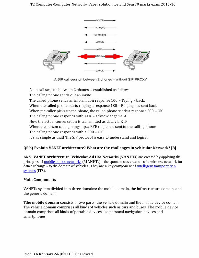
Example of SIP call Session between 2phones [10]
TE Computer-Computer Network- Paper solution for End Sem 70 marks exam 2015-16
Prof. B.A.Khivsara-SNJB’s COE, Chandwad
A sip call session between 2 phones is established as follows:
The calling phone sends out an invite
The called phone sends an information response 100 – Trying – back.
When the called phone starts ringing a response 180 – Ringing – is sent back
When the caller picks up the phone, the called phone sends a response 200 – OK
The calling phone responds with ACK – acknowledgement
Now the actual conversation is transmitted as data via RTP
When the person calling hangs up, a BYE request is sent to the calling phone
The calling phone responds with a 200 – OK.
It’s as simple as that! The SIP protocol is easy to understand and logical.
Q5 b) Explain VANET architecture? What are the challenges in vehicular Network? [8]
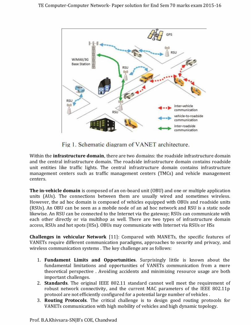
ANS: VANET Architecture: Vehicular Ad Hoc Networks (VANETs) are created by applying the
principles of mobile ad hoc networks (MANETs) - the spontaneous creation of a wireless network for data exchange - to the domain of vehicles. They are a key component of intelligent transportation
systems (ITS).
Main Components
VANETs system divided into three domains: the mobile domain, the infrastructure domain, and the generic domain.
Tthe mobile domain consists of two parts: the vehicle domain and the mobile device domain. The vehicle domain comprises all kinds of vehicles such as cars and buses. The mobile device domain comprises all kinds of portable devices like personal navigation devices and smartphones.
TE Computer-Computer Network- Paper solution for End Sem 70 marks exam 2015-16
Prof. B.A.Khivsara-SNJB’s COE, Chandwad
Within the infrastructure domain, there are two domains: the roadside infrastructure domain and the central infrastructure domain. The roadside infrastructure domain contains roadside unit entities like traffic lights. The central infrastructure domain contains infrastructure management centers such as traffic management centers (TMCs) and vehicle management centers.
The in-vehicle domain is composed of an on-board unit (OBU) and one or multiple application units (AUs). The connections between them are usually wired and sometimes wireless. However, the ad hoc domain is composed of vehicles equipped with OBUs and roadside units (RSUs). An OBU can be seen as a mobile node of an ad hoc network and RSU is a static node likewise. An RSU can be connected to the Internet via the gateway; RSUs can communicate with each other directly or via multihop as well. There are two types of infrastructure domain access, RSUs and hot spots (HSs). OBUs may communicate with Internet via RSUs or HSs
Challenges in vehicular Network [11]: Compared with MANETs, the specific features of VANETs require different communication paradigms, approaches to security and privacy, and wireless communication systems . The key challenge are as follows:
1. Fundament Limits and Opportunities. Surprisingly little is known about the fundamental limitations and opportunities of VANETs communication from a more theoretical perspective . Avoiding accidents and minimizing resource usage are both important challenges.
2. Standards. The original IEEE 802.11 standard cannot well meet the requirement of robust network connectivity, and the current MAC parameters of the IEEE 802.11p protocol are not efficiently configured for a potential large number of vehicles .
3. Routing Protocols. The critical challenge is to design good routing protocols for VANETs communication with high mobility of vehicles and high dynamic topology.
TE Computer-Computer Network- Paper solution for End Sem 70 marks exam 2015-16
Prof. B.A.Khivsara-SNJB’s COE, Chandwad
4. Connectivity. Primary challenge in designing vehicular communication is to provide good delay performance under the constraints of vehicular speeds, high dynamic topology, and channel bandwidths .
5. Cross-Layer. In order to support real-time and multimedia applications, an available solution is to design cross-layer among original layers.
6. Cooperative Communication. The cooperation between vehicular clouds and the Internet clouds in the context of vehicular management applications has become a critical challenge to researchers.
7. Mobility. Mobility that is the norm for vehicular networks makes the topology change quickly. Mobility plays a key role in vehicular protocol design and modeling.
8. Security and Privacy. Tradeoff of the security and privacy is the biggest challenge under the requirement of efficiency.
9. Validation. It is necessary not only to assess the performance of VANETs in a real scenario but also to discover previously unknown and critical system properties.
Q6 a) What is DTN? Explain different layers of DTN? [8] Ans:
Delay-tolerant networking (DTN)[12] is an approach to computer network architecture that
seeks to address the technical issues in heterogeneous networks that may lack continuous
network connectivity. Examples of such networks are those operating in mobile or extreme
terrestrial environments, or planned networks in space.
Goals of DTN:
– Support interoperability across ‘radically heterogeneous’ networks
– Acceptable performance in high loss/delay/error/disconnected environments
– Decent performance for low loss/delay/errors
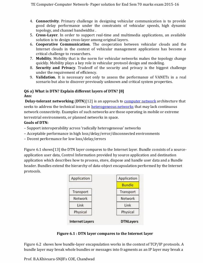
Figure 6.1 shows[13] the DTN layer compares to the Internet layer. Bundle consists of a source-
application user data, Control Information provided by source application and destination
application which describes how to process, store, dispose and handle user data and a Bundle
header. Bundles extend the hierarchy of data-object encapsulation performed by the Internet
protocols.
Figure 6.1 : DTN layer compares to the Internet layer
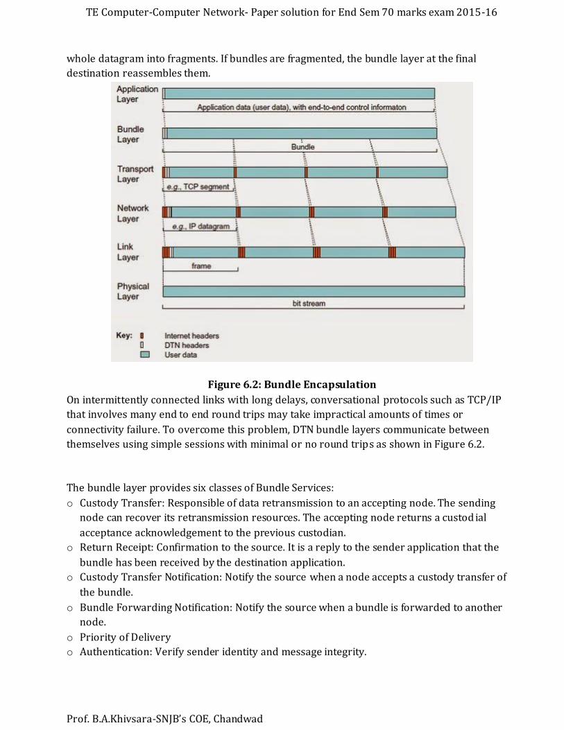
Figure 6.2 shows how bundle-layer encapsulation works in the context of TCP/IP protocols. A
bundle layer may break whole bundles or messages into fragments as an IP layer may break a
TE Computer-Computer Network- Paper solution for End Sem 70 marks exam 2015-16
Prof. B.A.Khivsara-SNJB’s COE, Chandwad
whole datagram into fragments. If bundles are fragmented, the bundle layer at the final
destination reassembles them.
Figure 6.2: Bundle Encapsulation
On intermittently connected links with long delays, conversational protocols such as TCP/IP
that involves many end to end round trips may take impractical amounts of times or
connectivity failure. To overcome this problem, DTN bundle layers communicate between
themselves using simple sessions with minimal or no round trips as shown in Figure 6.2.
The bundle layer provides six classes of Bundle Services:
o Custody Transfer: Responsible of data retransmission to an accepting node. The sending
node can recover its retransmission resources. The accepting node returns a custod ial
acceptance acknowledgement to the previous custodian.
o Return Receipt: Confirmation to the source. It is a reply to the sender application that the
bundle has been received by the destination application.
o Custody Transfer Notification: Notify the source when a node accepts a custody transfer of
the bundle.
o Bundle Forwarding Notification: Notify the source when a bundle is forwarded to another
node.
o Priority of Delivery
o Authentication: Verify sender identity and message integrity.

TE Computer-Computer Network- Paper solution for End Sem 70 marks exam 2015-16
Prof. B.A.Khivsara-SNJB’s COE, Chandwad
Q6 b) Explain H3.2.3 protocol used in VoIP? [6]
Ans: [14][15]
"Packet-based multimedia communications systems", better known as H.323, is an
international Voice over IP standard defined by the International Telecommunications Union.
The first version of H.323 was published in 1996, the last (6 th) version appeared in 2006.
When dealing with H.323, it is good to realize that it is not a single protocol but rather an entire
group of protocols. The individual protocols used under the umbrella of H.323 include:
H.225.0 for call signalling;
Q.931, a protocol borrowed from ISDN, also used for call signalling;
H.245 for negotiating audio/video channel parameters;
H.235 for security and authentication;
RTP, the Real Time Protocol defined by IETF, used to transmit audio/video streams;
H.450.x for additional services like call transfer, call diversion, etc.
Components of H.323
H.323 defines four logical components viz., Terminals, Gateways, Gatekeepers and Multipoint
Control Units (MCUs). Terminals, gateways and MCUs are known as endpoints.
1 Terminals
These are the LAN client endpoints that provide real time, two way communications. All H.323
terminals have to support H.245, Q.931, Registration Admission Status (RAS) and Real Time
Transport Protocol (RTP).
2 Gateways
An H.323 gateway is an endpoint on the network which provides for real-time, two-way
communications between H.323 terminals on the IP network and other ITU terminals on a
switched based network, or to another H.323 gateway.
3 Gatekeepers
It is the most vital component of the H.323 system and dispatches the duties of a "manager". It
acts as the central point for all calls within its zone (A zone is the aggregation of the gatekeeper
and the endpoints registered with it) and provides services to the registered endpoints.
4 Multipoint Control Units (MCU)
The MCU is an endpoint on the network that provides the capability for three or more
terminals and gateways to participate in a multipoint conference. The MCU consists of a
mandatory Multipoint Controller (MC) and optional Multipoint Processors (MP).

TE Computer-Computer Network- Paper solution for End Sem 70 marks exam 2015-16
Prof. B.A.Khivsara-SNJB’s COE, Chandwad
Fig 6.3 components of H.323
H.323 Protocol Stack
The following figure [Fig 6.4] shows the H.323 protocol stack. The audio, video and registration
packets use the unreliable User Datagram Protocol (UDP) while the data and control
application packets use the reliable Transmission Control Protocol (TCP) as the transport
protocol. Except for the T.120 protocol, the other protocols are described in the paper.
Fig 6.4. The protocol stack of H.323
Q6 c) What are applications of VoIP? [2]
Ans:[16]
VoIP Applications:
Office-to-office communication
Off-net calling

TE Computer-Computer Network- Paper solution for End Sem 70 marks exam 2015-16
Prof. B.A.Khivsara-SNJB’s COE, Chandwad
Create off-premise extensions
Replace expensive tie lines
Click-2-Dial system with VOIP
Video calling over world
VoIP Application examples:
Skype
Google hangouts
VOIPStunt
PeerMe
iChat
iCall
Q7a) What is Virtualization? Explain. [6]
Ans: In computing, virtualization refers to the act of creating a virtual (rather than actual)
version of something, including virtual computer hardware platforms, operating systems,
storage devices, and computer network resources.
Types of Virtualization are:
Storage virtualization: the amalgamation of multiple network storage devices into what
appears to be a single storage unit.
Server virtualization: the partitioning a physical server into smaller virtual servers.
Operating system-level virtualization: a type of server virtualization technology which
works at the operating system (kernel) layer.
Network virtualization: using network resources through a logical segmentation of a
single physical network.
Application virtualization
Q7b) Explain ATM Architecture. [6]
Ans:[17]
The asynchronous transfer mode (ATM) protocol architecture is designed to support the
transfer of data with a range of guarantees for quality of service. The user data is divided into
small, fixed-length packets, called cells, and transported over virtual connections. ATM
operates over high data rate physical circuits, and the simple structure of ATM cells allows
switching to be performed in hardware, which improves the speed and efficiency of ATM
switches.
Figure 7.1 shows the reference model for ATM. The first thing to notice is that, as well as layers,
the model has planes. The functions for transferring user data are located in the user plane; the
functions associated with the control of connections are located in the control plane; and the

TE Computer-Computer Network- Paper solution for End Sem 70 marks exam 2015-16
Prof. B.A.Khivsara-SNJB’s COE, Chandwad
co-ordination functions associated with the layers and planes are located in the ma nagement
planes.
Figure 7.1 ATM reference model
The three-dimensional representation of the ATM protocol architecture is intended to portray
the relationship between the different types of protocol. The horizontal layers indicate the
encapsulation of protocols through levels of abstraction as one layer is built on top of another,
whereas the vertical planes indicate the functions that require co-ordination of the actions
taken by different layers. An advantage of dividing the functions into control and u ser planes is
that it introduces a degree of independence in the definition of the functions: the protocols for
transferring user data (user plane) are separated from the protocols for controlling
connections (control plane).
The protocols in the ATM layer provide communication between ATM switches while the
protocols in the ATM adaptation layer (AAL) operate end-to-end between users. This is
illustrated in the example ATM network in Figure 25.
Figure 7.2 ATM network

TE Computer-Computer Network- Paper solution for End Sem 70 marks exam 2015-16
Prof. B.A.Khivsara-SNJB’s COE, Chandwad
Two types of interface are identified in Figure 7.2: one between the users and the network
(user-network interface), and the other between the nodes (switches) within the network
(network-node interface).
Q7 c) Write short note on GMPLS. [6]
Ans:
Generalized Multi-Protocol Label Switching (GMPLS) is a protocol suite extending MPLS to
manage further classes of interfaces and switching technologies other than packet interfaces
and switching, such as time division multiplexing, layer-2 switching, wavelength switching and
fiber-switching.
Differences between MPLS and GMPLS
Generalized MPLS differs from traditional MPLS[2] in that it extends support to multiple types
of switching such as TDM, wavelength and fiber (port) switching. For instance, GMPLS is the de
facto control plane of wavelength switched optical network (WSON).[3][4] The support for the
additional types of switching has driven GMPLS to extend certain base functions of traditional
MPLS and, in some cases, to add functionality.
These changes and additions impact basic label-switched path (LSP) properties: how labels are
requested and communicated, the unidirectional nature of LSPs, how errors are propagated,
and information provided for synchronizing the ingress and egress LSRs.
GMPLS Operations [18]
Figure 7.3GMPLS Operations
The visual shows a typical modern-day networking scenario in which two clients (network
users) are interconnected across a path that implements several technologies.
Each user is connected to a router, probably across some type of LAN (not shown). The routers
are MPLS-aware (i.e., they are label switching routers (LSR)). Each router is served by an ATM

TE Computer-Computer Network- Paper solution for End Sem 70 marks exam 2015-16
Prof. B.A.Khivsara-SNJB’s COE, Chandwad
switch, perhaps in a carrier backbone network. Inside the carrier network, a SONET
infrastructure interconnects the ATM switches. The SONET nodes are likely to be arranged in
ring topologies (not shown). Finally, the SONET nodes are interconnected across a long -haul
optical backbone (i.e., the OTN).
Without GMPLS, establishing and managing such a connection would be extremely complex.
The coordination required among many different control plane protocols would be difficult to
achieve. With GMPLS, however, each layer technology views its segment of the overall
connection as a simple label switched path (LSP) that has certain operational parameters
associated with it. This process is implemented via label stacking.
How GMPLS works
GMPLS is based on Generalized Labels. The Generalized Label is a label that can represent
either (a) a single fiber in a bundle, (b) a single waveband within fiber, (c) a single wavelength
within a waveband (or fiber), or (d) a set of time-slots within a wavelength (or fiber). The
Generalized Label can also carry a label that represents a generic MPLS label, a Frame Relay
label, or an ATM label.
GMPLS is composed of three main protocols:
Resource Reservation Protocol with Traffic Engineering extensions (RSVP-TE) signaling
protocol.
Open Shortest Path First with Traffic Engineering extensions (OSPF-TE) routing
protocol.
Link Management Protocol (LMP).
GMPLS Goals
GMPLS provides a single control plane for all optical technologies and standardizes on an IP-
based signaling and control protocol. As the principal tool for the automatic optical network,
GMPLS supports capabilities and features that allow network operators to control their optical
devices. These capabilities span technologies and support a consistent level of service for
customers.
Automate end-to-end provisioning
Manage Network Resources
Support QoS
GMPLS Functions
Routing: Support OSPF link state routing protocol across packet and non- packet
technologies to allow path discovery based on bandwidth routing constraints.
Signaling: Use RSVP to establish and terminate traffic flow paths end-to-end in a mixed
technology environment.
TE Computer-Computer Network- Paper solution for End Sem 70 marks exam 2015-16
Prof. B.A.Khivsara-SNJB’s COE, Chandwad
Link Management: Use the Link Management Protocol (LMP) to discover and manage
adjacencies between GMPLS-capable devices.
Q8 a) Explain ATM header? Explain Application Adaptation Layer in detail. [8]
Ans:[16]
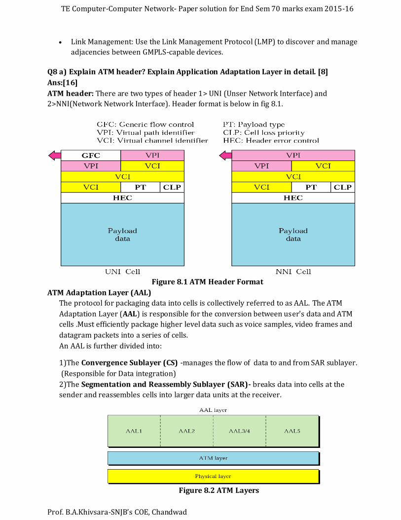
ATM header: There are two types of header 1> UNI (Unser Network Interface) and
2>NNI(Network Network Interface). Header format is below in fig 8.1.
Figure 8.1 ATM Header Format
ATM Adaptation Layer (AAL)
The protocol for packaging data into cells is collectively referred to as AAL. The ATM
Adaptation Layer (AAL) is responsible for the conversion between user's data and ATM
cells .Must efficiently package higher level data such as voice samples, video frames and
datagram packets into a series of cells.
An AAL is further divided into:
1)The Convergence Sublayer (CS) -manages the flow of data to and from SAR sublayer.
(Responsible for Data integration)
2)The Segmentation and Reassembly Sublayer (SAR)- breaks data into cells at the
sender and reassembles cells into larger data units at the receiver.
Figure 8.2 ATM Layers

TE Computer-Computer Network- Paper solution for End Sem 70 marks exam 2015-16
Prof. B.A.Khivsara-SNJB’s COE, Chandwad
There are 5 types of AAL headers as explained below:
• AAL1 – constant bit rate (CBR) video and voice
• AAL2 – variable bit rate (VBR) stream low-bit-rate traffic an short-frame traffic such
as audio
• (ex: mobile phone)
• AAL3/4 – connection-oriented/connectionless data
• AAL5 – SEAL (Simple and Efficient Adaptation Layer)- No sequencing and error control
mechanisms
Q8b) what are components of optical Network. [6]
Ans: Components of an optical networking system include:
• Fiber. Multi-mode or single-mode.
• Laser or LED light source.
• Multiplexer/demultiplexer, also called mux/demux, filter, or prism. These can include Optical
Add/Drop Multiplexer (OADM) and Reconfigurable Optical Add/Drop Multiplexer (ROADM).
• Optical switch, to direct light between ports without an optical-electrical-optical conversion
• Optical splitter, to send a signal down different fiber paths.
• Circulator, to tie in other components, such as an OADM.
• Optical amplifier.
Figure 8.3 optical network identifying key optical components
The end-to-end optical transmission involves both electrical and optical signal paths. To
perform conversion from electrical to optical domain, the optical transmitters are used,
while to perform conversion in opposite direction (optical to electrical conversion), the
optical receivers are used.
The optical fibers serve as foundation of an optical transmission system because the
optical fiber is used as a medium to transport the optical signals from source to
destination. The optical fibers attenuate the signal during transmission, and someone
has to use optical amplifiers, such as erbium-doped fiber amplifiers (EDFAs).
TE Computer-Computer Network- Paper solution for End Sem 70 marks exam 2015-16
Prof. B.A.Khivsara-SNJB’s COE, Chandwad
The simplest optical transmission system employs only one wavelength. The
wavelength division multiplexing (WDM) can be considered as an upgrade of the single-
wavelength system.
During transmission of WDM signals, occasionally one or several wavelengths are to be
added or dropped, which is performed by the optical component known as optica l add–
drop multiplexer (OADM).
The optical networks require the switching of information among different fibers, which
is performed in optical cross-connect (OXS).
To combine several distinct wavelength channels into composite channel, the
wavelength multiplexers are used.
On the other hand, to split the composite WDM channel into distinct wavelength
channels, the wavelength demultiplexers are used. To impose the information signal,
optical modulators are used. The optical modulators are commonly used in co mbination
with semiconductor lasers.[19]
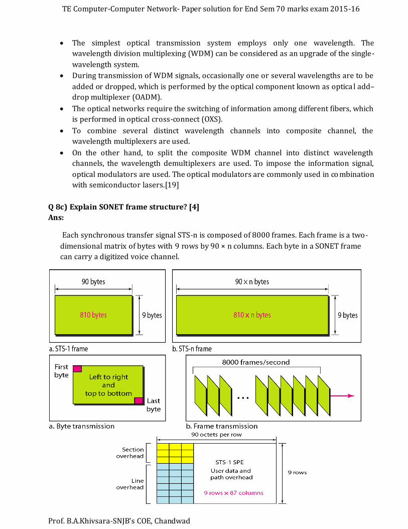
Q 8c) Explain SONET frame structure? [4]
Ans:
Each synchronous transfer signal STS-n is composed of 8000 frames. Each frame is a two-
dimensional matrix of bytes with 9 rows by 90 × n columns. Each byte in a SONET frame
can carry a digitized voice channel.

TE Computer-Computer Network- Paper solution for End Sem 70 marks exam 2015-16
Prof. B.A.Khivsara-SNJB’s COE, Chandwad
• In SONET, the data rate of an STS-n signal is n times the data rate of an STS-1 signal
• In SONET, the duration of any frame is 125 μs
References:
[1] http://mvn.edu.in/lms/mod/book/view.php?id=85&chapterid=28
[2] www.studioreti.it/slide/802-11-Frame_E_C.pdf
[3] http://www.wildpackets.com/resources/compendium/wireless_lan/wlan_packets
[4] https://en.wikipedia.org/wiki/Wireless_LAN
[5] http://www.wi-fiplanet.com/tutorials/article.php/1216351/80211-MAC-Layer-
Defined.htm
[6]http://www.slideshare.net/WayneJonesJnr/ch14-3361662
[7] http://ecomputernotes.com/computernetworkingnotes/communication-
networks/bluetooth
[8] https://en.wikipedia.org/wiki/Voice_over_IP
[9] https://en.wikipedia.org/wiki/Session_Initiation_Protocol
[10] http://www.miracall.cn/FAQ%20All%20Questions/faq-22-Sip%20ex.htm
[11] http://www.hindawi.com/journals/ijdsn/2015/745303/
[12] https://en.wikipedia.org/wiki/Delay-tolerant_networking
[13] http://knowledgewithoutlimitation.blogspot.in/2014/11/23-comparison-of-tcpip-and-
dtn.html
[14] http://toncar.cz/Tutorials/VoIP/VoIP_Protocols_Introducing_H323.html
[15] http://www.cse.wustl.edu/~jain/cis788-99/ftp/voip_protocols/
[16] https://bhavanakhivsara.wordpress.com/computer-networks/notespresentation/
[17] http://www.open.edu/openlearn/science-maths-technology/computing-and-ict/systems-
computer/protocols-multi-service-networks/content-section-4.1
[18] http://www.hill2dot0.com/wiki/index.php?title=GMPLS#GMPLS_Operations
[19] http://www.fs.com/optical-transmission-systems-classification-aid-353.html


![bhavanakhivsara.files.wordpress.com · Web viewSubject : Computer Networks Exam: ENDSEM Marks:70 Paper Solution By: Prof. B.A.Khivsara Q1 a) Differentiate between OSI and] : OSI Model](https://img.pdfslide.us/doc/110x75/5b2c0c607f8b9ae6278bc2a8/-web-viewsubject-computer-networks-exam-endsem-marks70-paper-solution-by.jpg)