Embed Size (px)
Citation preview
RANGELANDS 16(2), April 1994 41
PyrShaft: an inexpensive homemade drip torch Robert A. Nicholson
The drip torch is a superior method of igniting pres- cribed fires on most types of land, especially grassland. A typical commercial drip torch is reasonably safe and effective, but can be awkward to use and fairly expensive ($125-$150). A home-made version (PyrShaft) can be constructed from ordinary, locally obtainable, and inex- pensive materials, most of which are recycled. The total cost of materials for construction should be around $20.00. Because of its design the PyrShaft is more easily handled in the field, enabling its user to be further from the ignition point. It places the burning fuel low in the vegetation, which gives more effective ignition, and it can accommodate propelled uses that the shorter commer- cial styles cannot. It is constructed of rugged materials and can withstand substantial abuse. Because it is longer than commercial drip torches, the chance that burning fuel will inadvertently drip on its user is virtually nil. Its wide-mouthed filler opening, allows for easy, quick, and safe transfer of fuel to the PyrS halt.
Materials:
Fuel Reservoir • used automobile drive shaft • used bung and bunghole from a 30- or 50-gallon steel drum (2"
pipe thread) • gasket for filler opening • 6" of 1/4" used or new steel rod stock • air inlet valve (3/8" or 1/4" thread radiator drain valve)
Dra9 Rod • 27" of 3/8" or 7/16" used or new steel rod stock
Handle • 24-30" of 3/4" used or new steel conduit • stainless steel radiator hose clamps (2 large or 4 small)
Dripper • 12" of 1/4" used or new copper tubing • dripper flow control valve (3/8" or 1/4" pipe thread) • spring and ball check valve (3/8" or 1/4" pipe thread) • adapter (pipe to 1/4" copper tubing, flare or ferrule)
Begin the PyrS halt project by visiting an auto parts or hardware store to purchase the brass and copper mate- rials for the dripper. Next visit an auto salvage yard to obtain a scrap automobile drive shaft. Be sure to ask for those that you can buy as scrap, rather than as a used part, which is usually more expensive. Scrap shafts might be slightly dented or otherwise not true enough for use on a vehicle. Although any thin-walled steel tubing could be used, a used drive shaft is ideal for this, because the length is correct, they are readily available, inexpen-
sive, thin-walled, and the bottom end is already partially finished. Steel rod and conduit for the project does not have to be new or perfect material.
A driveshaft diameter of 2.75" or larger will work, but remember that small changes in diameter will result in
large changes in volume. A cylinder 52" long and 2.75" in diameter, will contain about 4.5 quarts of fuel. At the same length, adding only 0.5" in diameter will increase the volume by another quart with a negligible increase in container weight. When it is in use, it is better to have to refuel the torch less often. A diameter of 2.75" is the right size for easy installation of a wide-mouthed filler opening that can be scavenged from an old steel drum; a smaller shaft would work, but another type of filler opening will need to be devised.
Compare weights of drive shafts if possible. All other considerations aside, the thinner the wall of the drive shaft, the lighter it will be. As described herein, the Pyr- Shaft weighs about 13 lb. without fuel. However, when in use the PyrShaft is dragged rather than carried, thus the ground actually supports much of its weight. The empty dragging weight is about 7 lb. The raw drive shaft will have attachments for universal joints welded to both ends or at one end it might have a spline. Given a choice, a spline is probably best, but diameter of the shaft is probably a more important consideration.
Obtain the entire filler closure from an old steel drum, which normally has the same thread as 2" pipe. Remove the entire unit, both the female (bunghole) and male (bung) portions. Be sure to remove enough of the metal surrounding the bunghole such that its diameter is as large or larger than the diameter of the drive shaft to be used. Bungs come in many different styles. The preferred type is made of steel (not cast aluminum) and has an external lip that is large enough that a flat rubber or neoprene gasket can be used to seal it.
Construction
Shaft and Drag Bar If the drive shaft has a spline on one end, saw off the
universal joint attachment at the opposite end. If the shaft has universal joint attachments at both ends, saw off either end. The sawed end (top) will become the fuel filler opening, whereas the other end (bottom) will be used to attach the drag rod and fuel dripper. Next create the opening to connect the dripper by boring a hole through the center of the bottom end of the drive shaft. Then tap the hole with the appropriate pipe thread for the fuel outlet control valve (1/4"—3/8"). Some cleaning of the inside of the drive shaft might be necessary, if it contains any loose rust or other debris.
Bend the 27" piece of rod in the shape of a U. Bend the The author is with Fort Hays State University, 600 Park Street, Hays, KS
67601-4099.
42 RANGELANDS 16(2), April 1994
arms inward and test it for welding placement on the bottom of the drive shaft, then trim any unnecessary material in order to make effective welds between the rod and drive shaft. If the bottom end has a spline, cut some of it off, leaving about 1-1.5" (enough to use to weld to the drag bag and to receive the bore and tap for the fuel outlet). If the bottom end has a universal joint, trim the arms appropriately to receive the U-shaped drag bar and weld it to the bottom end of the drive shaft.
Filler Opening and Air Vent Prepare the filler opening by cutting and grinding
around the bunghole to make it exactly fit the top end of the drive shaft, and braze it to the end of the drive shaft to produce a leak-proof seam. Obtain or make a flat gasket of appropriate size. Bore and tap the center of the bung for an air inlet valve. Bend the 0.25" steel rod in the shape of a U, such that the arms of the U can be welded to the top side of the edges of the bung. This U-bar is necessary to protect the air valve and creates a handle to easily open and close the bung. Instalithe air inlet vent in the bung. A radiator drain valve works best, but another type of small valve would work. This valve is important so that the air vent can be closed and when not in use the PyrShaft can be laid flat without leaking fuel. Alternatively install a spring and ball type of check valve, which is theoretically more convenient, but is sensitive and tends to leak.
Handle Bend the conduit in the shape of the handle as shown.
Flatten the ends of the conduit in a vice, then slightly contour the flattened portions to match that of the drive shaft. Attach the handle with radiator hose clamps. Weld- ing the handle to the PyrShaft is not recommended because using clamps allows for easy repositioning of the handle. This design allows for both unlimited adjustment to achieve a comfortable dragging position and correct bal- ance for carrying.
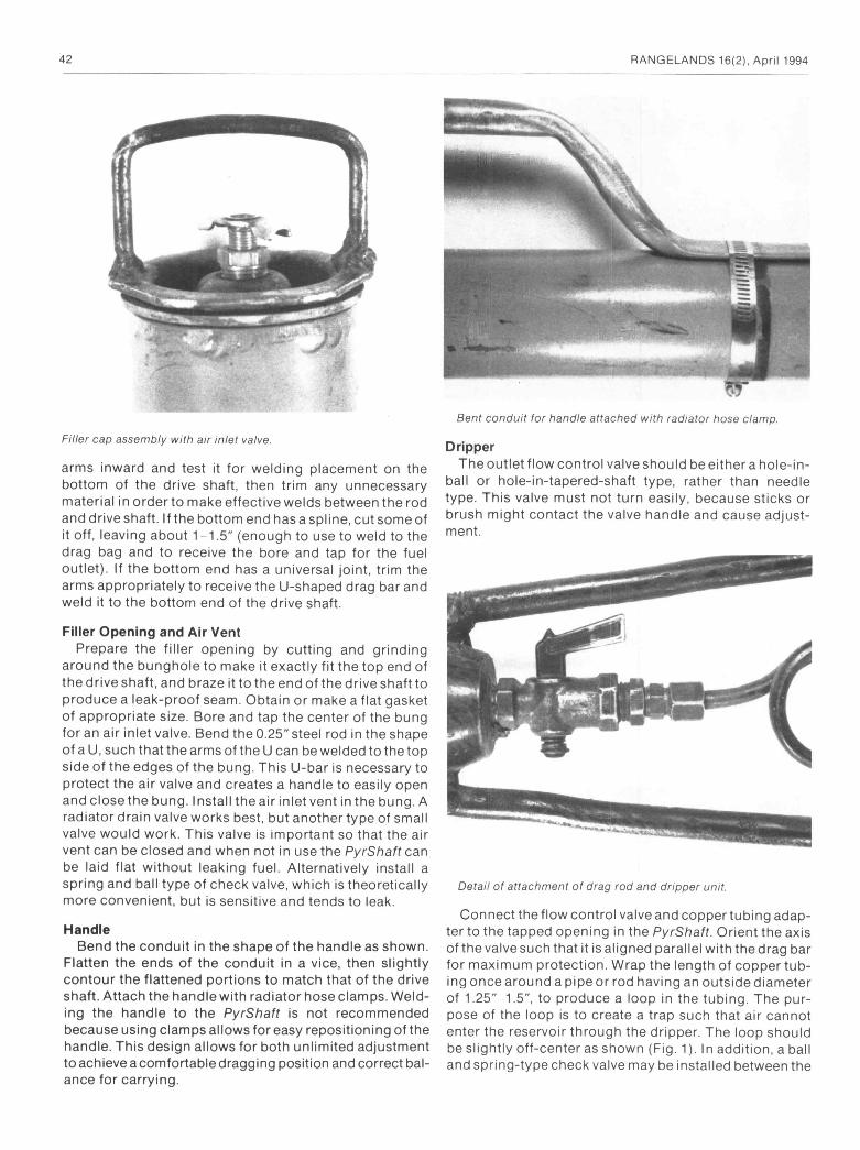
Dripper The outlet flow control valve should be either a hole-in-
ball or hole-in-tapered-shaft type, rather than needle type. This valve must not turn easily, because sticks or brush might contact the valve handle and cause adjust- ment.
Connect the flow control valve and copper tubing adap- ter to the tapped opening in the PyrShaft. Orient the axis of the valve such that it is aligned parallel with the drag bar for maximum protection. Wrap the length of copper tub- ing once around a pipe or rod having an outside diameter of 1.25"-1.5", to produce a loop in the tubing. The pur- pose of the loop is to create a trap such that air cannot enter the reservoir through the dripper. The loop should be slightly off-center as shown (Fig. 1). In addition, a ball and spring-type check valve may be installed between the
Filler cap assembly with air inlet valve.
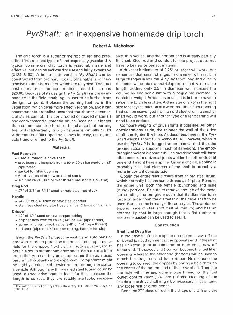
Bent conduit for handle attached with radiator hose clamp.
Detail of attachment of drag rod and dripper unit.
RANGELANDS 16(2), April 1994 43
copper conduit handl, tubing filler cap
air Inlet valve
cap handl, hos, clamps
•
. dripper
drlv. shaft
flow control valv, drag rod
63"
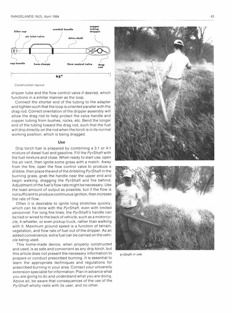
Construction layout.
dripper tube and the flow control valve if desired, which functions in a similar manner as the loop.
Connect the shorter end of the tubing to the adapter and tighten such that the loop is oriented parallel with the drag rod. Correct orientation of the dripper assembly will allow the drag rod to help protect the valve handle and copper tubing from bushes, rocks, etc. Bend the longer end of the tubing toward the drag rod, such that the fuel will drip directly on the rod when thetorch is in its normal working position, which is being dragged.
Use
Drip torch fuel is prepared by combining a 3:1 or 4:1
mixture of diesel fuel and gasoline. Fill the PyrShaft with the fuel mixture and close. When ready to start use, open the air vent, then ignite some grass with a match. Away from the fire, open the flow control valve to produce a dribble, then place the end of the dribbling PyrShaft in the burning grass, grab the handle near the upper end and begin walking, dragging the PyrShaft and fire behind. Adjustment of the fuel's flow rate might be necessary. Use the least amount of output as possible, but if the flow is not sufficient to produce continuous ignition, then increase the rate of flow.
Often it is desirable to ignite long stretches quickly, which can be done with the PyrShaft, even with limited personnel. For long fire lines, the PyrSha ft's handle can be tied or wired to the back of vehicle, such as a motorcy- cle, 4-wheeler, or even pickup truck, rather than walking with it. Maximum ground speed is a function of terrain, vegetation, and flow rate of fuel out of the dripper. As an added convenience, extra fuel can be carried on the vehi- cle being used.
This home-made device, when properly constructed and used, is as safe and convenient as any drip torch, but this article does not present the necessary information to prepare or conduct prescribed burning. It is essential to learn the appropriate techniques and regulations for prescribed burning in your area. Contact your university extension specialist for information. Plan in advance what you are going to do and understand what you are doing. Above all, be aware that consequences of the use of the PyrShaft wholly rests with its user, and no other.
p'rShaft in use.