Embed Size (px)
Citation preview
MI
pyrotenax mineral insulated (MI) wiring cable system
the ultimate fire survival cable system
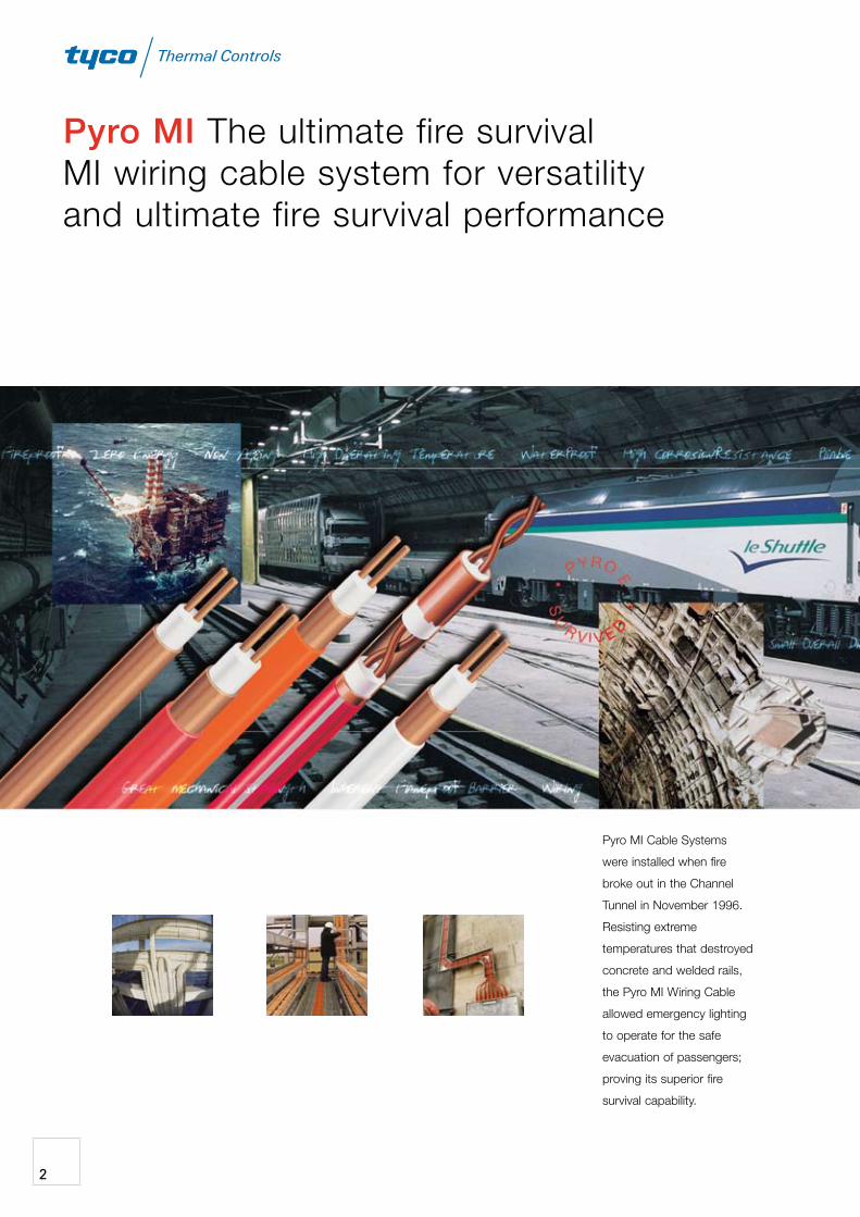
Pyro MI the ultimate fire survival MI wiring cable system for versatility and ultimate fire survival performance
pyro MI cable systems
were installed when fire
broke out in the channel
tunnel in November 1996.
resisting extreme
temperatures that destroyed
concrete and welded rails,
the pyro MI Wiring cable
allowed emergency lighting
to operate for the safe
evacuation of passengers;
proving its superior fire
survival capability.
2
Pyro MI Fire Survival Cable System - provides the ideal solution to many difficult
and demanding wiring installations making a permanent and dependable wiring
cable system for all low and medium voltage applications. safe in hazardous
installations and radio active environments. Exceeds all world wide fire performance
standards. the pyro MI cable system is the natural choice for domestic,
commercial and industrial applications.
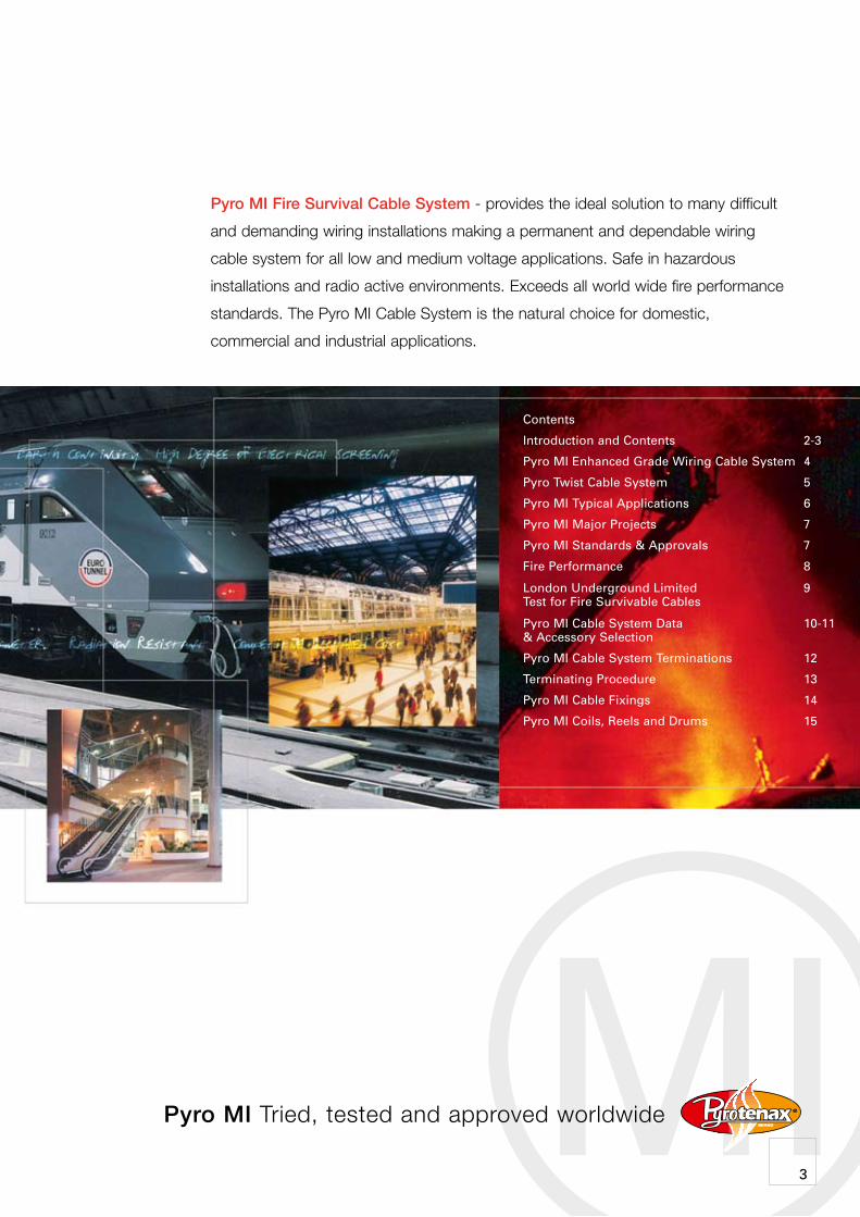
Contents
Introduction and Contents 2-3
Pyro MI Enhanced Grade Wiring Cable System 4
Pyro Twist Cable System 5
Pyro MI Typical Applications 6
Pyro MI Major Projects 7
Pyro MI Standards & Approvals 7
Fire Performance 8
London Underground Limited 9 Test for Fire Survivable Cables
Pyro MI Cable System Data 10-11 & Accessory Selection
Pyro MI Cable System Terminations 12
Terminating Procedure 13
Pyro MI Cable Fixings 14
Pyro MI Coils, Reels and Drums 15
MIPyro MI tried, tested and approved worldwide
3
Pyro MI Range The standard range of Pyro MI Cable provides the ideal solution for almost all electrical circuits in the low voltage category.
Two voltage grades - 500 and 750 Volts, are available with conductors from 1.0 sq.mm to 240 sq.mm. A full range of complementary accessories and tools provides a complete wiring system supplied and supported by the “Genuine Pyrotenax” component assurance.
Pyro MI Enhanced Grade Wiring Cable System
Pyro MI Benefits
A Pyro MI survives the fire test requirements for enhanced grade cables as defined in BS 5839: part 1.
A Peace of mind from the third party (LPCB) approval for categories C, W and Z in BS 6387.
A Also attains categories C, W and Z of BS 6387 with one single cable sample.
Pyro MI Construction
With a basic inorganic construction of a copper sheath and conductors, together with a mineral insulant, the cable provides a unique combination of dependability, versatility and permanence.
This construction, with the melting points of 1083°C and 2800°C for the copper and the insulant respectively, provides the unsurpassed Fire Survival properties which enable the cable to continue to carry current at temperatures in excess of 1000°C.
Pyro MI Construction Characteristics
A Fireproof
A High Operating Temperatures
A Inherent Flameproof Barrier
A Zero Energy
A Non-Ageing
A Great Mechanical Strength
A Small Overall Diameter
A Pliable
A Wiring Cable and Conduit Combined
A Competitive Installed Cost
A High Degree of Electrical Screening
A Radiation Resistant
A Integral Earth Continuity
A High Corrosion Resistance
A Waterproof
pyro MI Enhanced Grade Mineral Insulated Wiring cables
4
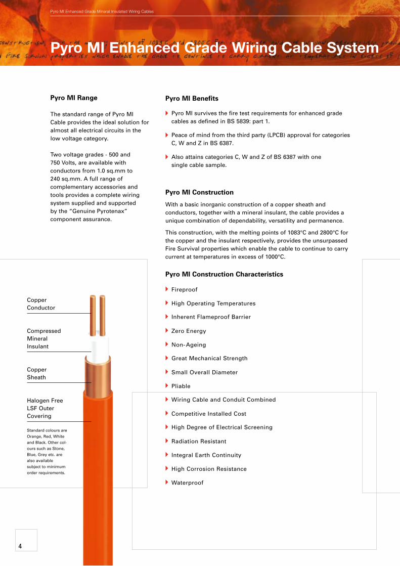
Copper Conductor
Compressed Mineral Insulant
Copper Sheath
Halogen Free LSF Outer Covering
Standard colours are Orange, Red, White and Black. Other col-ours such as Stone, Blue, Grey etc. are also available subject to minimum order requirements.
Pyro Twist Additional Characteristics and Advantages
A Twisted conductor configuration with a solid copper screen.
A Pyro Twist available in red (other colours available upon request).
A Pyro Twist uses standard accessories for the equivalent Pyro MI Light Duty cable size.
A Pyro Twist can be installed and terminated by following the normal procedures for Pyro MI Cable.
A The twisted copper conductor configuration enhances the EMC noise rejection characteristics, reducing the possibility of system malfunction.
A The exceptionally low impedance of the solid copper sheath provides a superior EMC screening than other cable systems.
A Minimal smoke obscuration in the event of fire.
Pyro Twist Cable System
Pyro Twist Cables
Pyro Twist is a range of communication and signal cables for life preservation and integrated building management systems.
They have been developed from the proven characteristics of Pyro MI to maintain the security of vital signals in communication and data networks, particularly in hostile conditions.
5
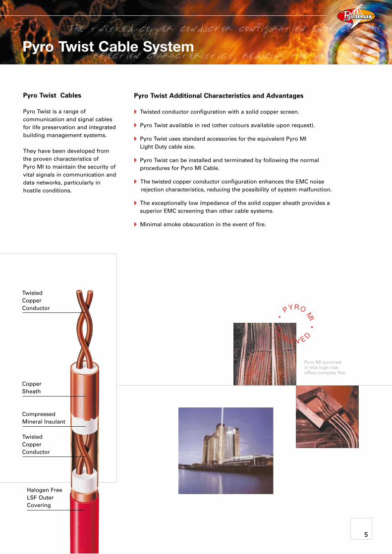
Twisted Copper Conductor
Copper Sheath
Compressed Mineral Insulant
Twisted Copper Conductor
Pyro MI survived in this high rise office complex fire
Halogen Free LSF Outer Covering
MI
Moving Walkways
Car Parking
Public Buildings Metro Links
Hotels
Shopping Complexes
Building Services
Offshore
Rail Tunnels
Road Tunnels
Dock and Harbour
Original Equipment
Building Exteriors
Power Generating
Escalators
Transport/Interchanges
Petrol Stations
Petrochemicals
Airport
Water Treatment
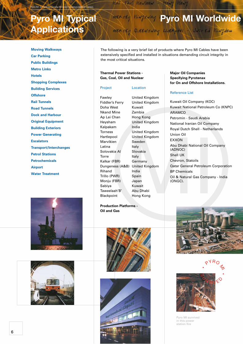
The following is a very brief list of products where Pyro MI Cables have been extensively specified and installed in situations demanding circuit integrity in the most critical situations.
Thermal Power Stations - Gas, Coal, Oil and Nuclear
Project Location
Fawley United Kingdom Fiddler’s Ferry United Kingdom Doha West Kuwait Nkand Mine Zambia Ap Lei Chan Hong Kong Heysham United Kingdom Kalpakam India Torness United Kingdom Hartlepool United Kingdom Marvikien Sweden Latina Italy Solovakia Al Slovakia Torre Italy Kalkar (FBR) Germany Dungeness (A&B) United Kingdom Rihand India Trillo (PWR) Spain Monju (FBR) Japan Sabiya Kuwait Taweelaah’B’ Abu Dhabi Blackpoint Hong Kong
Production Platforms - Oil and Gas
Major Oil Companies Specifying Pyrotenax for On and Offshore Installations.
Reference List
Kuwait Oil Company (KOC)
Kuwait National Petroleum Co (KNPC)
ARAMCO
Petromin - Saudi Arabia
National Iranian Oil Company
Royal Dutch Shell - Netherlands
Union Oil
EXXON
Abu Dhabi National Oil Company (ADNOC)
Shell UK
Chevron, Statoils
Qatar General Petroleum Corporation
BP Chemicals
Oil & Natural Gas Company - India (ONGC).
Pyro MI Typical Applications
Pyro MI Worldwide Major Projects
pyro MI Enhanced Grade Mineral Insulated Wiring cables
6
Pyro MI survived in this power station fire
5
Pyro MI Worldwide Major Projects
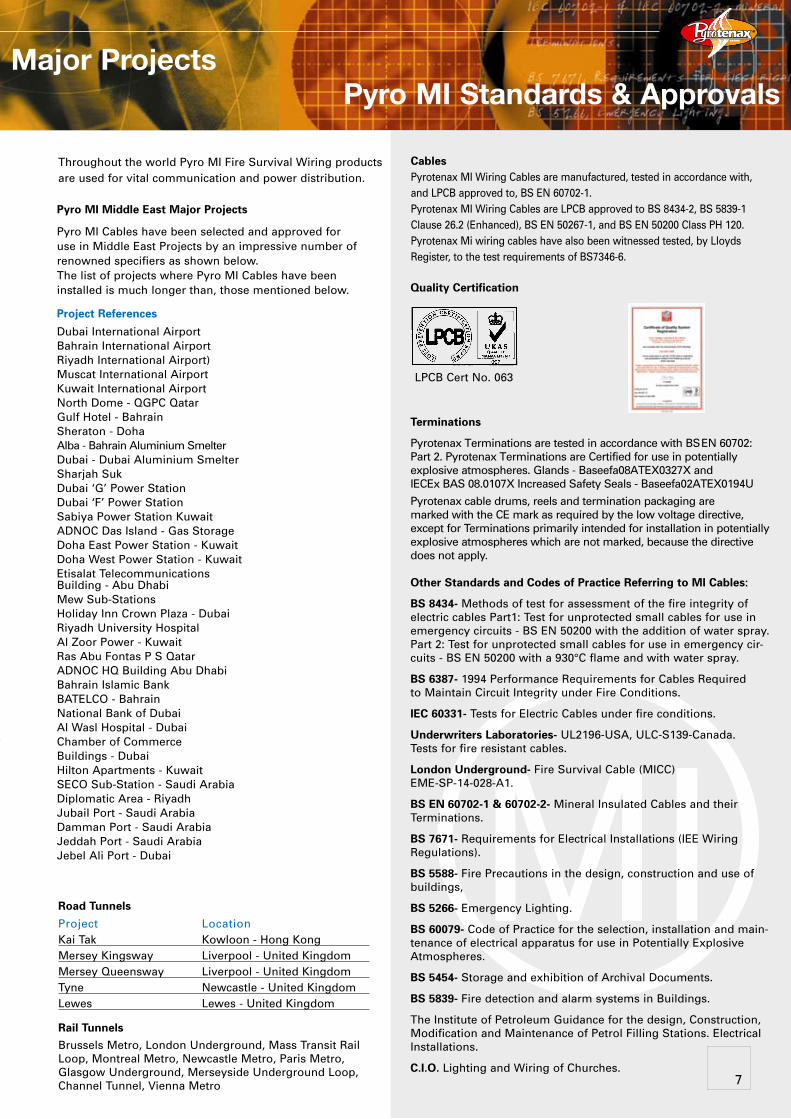
Throughout the world Pyro MI Fire Survival Wiring products are used for vital communication and power distribution.
Pyro MI Middle East Major Projects
Pyro MI Cables have been selected and approved for use in Middle East Projects by an impressive number of renowned specifiers as shown below. The list of projects where Pyro MI Cables have been installed is much longer than, those mentioned below.
Project References
Dubai International Airport Bahrain International Airport Riyadh International Airport) Muscat International Airport Kuwait International Airport North Dome - QGPC Qatar Gulf Hotel - Bahrain Sheraton - Doha Alba - Bahrain Aluminium Smelter Dubai - Dubai Aluminium Smelter Sharjah Suk Dubai ‘G’ Power Station Dubai ‘F’ Power Station Sabiya Power Station Kuwait ADNOC Das Island - Gas Storage Doha East Power Station - Kuwait Doha West Power Station - Kuwait Etisalat Telecommunications Building - Abu DhabiMew Sub-Stations Holiday Inn Crown Plaza - Dubai Riyadh University Hospital Al Zoor Power - Kuwait Ras Abu Fontas P S Qatar ADNOC HQ Building Abu Dhabi Bahrain Islamic Bank BATELCO - Bahrain National Bank of Dubai Al Wasl Hospital - Dubai Chamber of Commerce Buildings - Dubai Hilton Apartments - KuwaitSECO Sub-Station - Saudi Arabia Diplomatic Area - Riyadh Jubail Port - Saudi Arabia Damman Port - Saudi Arabia Jeddah Port - Saudi Arabia Jebel Ali Port - Dubai
Road Tunnels
Project LocationKai Tak Kowloon - Hong Kong Mersey Kingsway Liverpool - United Kingdom Mersey Queensway Liverpool - United Kingdom Tyne Newcastle - United Kingdom Lewes Lewes - United Kingdom
Rail Tunnels
Brussels Metro, London Underground, Mass Transit Rail Loop, Montreal Metro, Newcastle Metro, Paris Metro, Glasgow Underground, Merseyside Underground Loop, Channel Tunnel, Vienna Metro
MI
Cables Pyrotenax MI Wiring Cables are manufactured, tested in accordance with, and LPCB approved to, BS EN 60702-1.Pyrotenax MI Wiring Cables are LPCB approved to BS 8434-2, BS 5839-1 Clause 26.2 (Enhanced), BS EN 50267-1, and BS EN 50200 Class PH 120. Pyrotenax Mi wiring cables have also been witnessed tested, by Lloyds Register, to the test requirements of BS7346-6.
Pyro MI Standards & Approvals
7
Quality Certification
Terminations
Pyrotenax Terminations are tested in accordance with BS EN 60702: Part 2. Pyrotenax Terminations are Certified for use in potentially
explosive atmospheres. Glands - Baseefa08ATEX0327X and IECEx BAS 08.0107X Increased Safety Seals - Baseefa02ATEX0194U
Pyrotenax cable drums, reels and termination packaging are marked with the CE mark as required by the low voltage directive, except for Terminations primarily intended for installation in potentially explosive atmospheres which are not marked, because the directive does not apply.
Other Standards and Codes of Practice Referring to MI Cables:
BS 8434- Methods of test for assessment of the fire integrity of electric cables Part1: Test for unprotected small cables for use in emergency circuits - BS EN 50200 with the addition of water spray.Part 2: Test for unprotected small cables for use in emergency cir-cuits - BS EN 50200 with a 930°C flame and with water spray.
BS 6387- 1994 Performance Requirements for Cables Required to Maintain Circuit Integrity under Fire Conditions.
IEC 60331- Tests for Electric Cables under fire conditions.
Underwriters Laboratories- UL2196-USA, ULC-S139-Canada. Tests for fire resistant cables.
London Underground- Fire Survival Cable (MICC) EME-SP-14-028-A1.
BS EN 60702-1 & 60702-2- Mineral Insulated Cables and their Terminations.
BS 7671- Requirements for Electrical Installations (IEE Wiring Regulations).
BS 5588- Fire Precautions in the design, construction and use of buildings,
BS 5266- Emergency Lighting.
BS 60079- Code of Practice for the selection, installation and main-tenance of electrical apparatus for use in Potentially Explosive Atmospheres.
BS 5454- Storage and exhibition of Archival Documents.
BS 5839- Fire detection and alarm systems in Buildings.
The Institute of Petroleum Guidance for the design, Construction, Modification and Maintenance of Petrol Filling Stations. Electrical Installations.
C.I.O. Lighting and Wiring of Churches.
LPCB Cert No. 063
MI
Fire Performance
pyro MI Enhanced Grade Mineral Insulated Wiring cables
Fire Performance BS 6387 Performance Requirements for Cables Required to Maintain Circuit Integrity under Fire Conditions.
This standard details the following tests to categorise cables according to their fire withstand capabilities.
8
“Beyond the Standard... Pyro MI Cable can easily comply and
withstand the most onerous categories of C, W and Z
using one single Cable Sample
Pyro MI easily meets and exceeds the BS 5839-1 Enhanced and Standard Grade Requirements
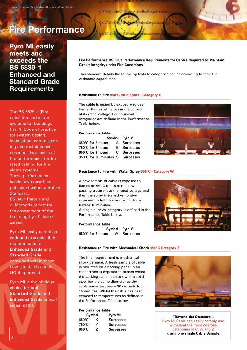
Resistance to Fire 950°C for 3 hours - Category C
The cable is tested by exposure to gas burner flames while passing a current at its rated voltage. Four survival categories are defined in the Performance Table below.
Performance Table Symbol Pyro MI 650°C for 3 hours A Surpasses 750°C for 3 hours B Surpasses 950°C for 3 hours C Surpasses 950°C for 20 minutes S Surpasses
Resistance to Fire with Water Spray 650°C - Category W A new sample of cable is exposed to flames at 650°C for 15 minutes whilst passing a current at the rated voltage and then the spray is turned on to give exposure to both fire and water for a further 15 minutes. A single survival category is defined in the Performance Table below.
Performance Table Symbol Pyro MI 650°C for 3 hours W Surpasses
Resistance to Fire with Mechanical Shock 950°C Category Z The final requirement is mechanical shock damage. A fresh sample of cable is mounted on a backing panel in an S-bend and is exposed to flames whilst the backing panel is struck with a solid steel bar the same diameter as the cable under test every 30 seconds for 15 minutes. Whilst the cable has been exposed to temperatures as defined in the Performance Table below.
Performance Table Symbol Pyro MI 650°C X Surpasses 750°C Y Surpasses 950°C Z Surpasses
The BS 5839-1 (Fire detection and alarm systems for buildings - Part 1: Code of practice for system design, installation, commission-ing and maintenance) describes two levels of fire performance for fire rated cabling for fire alarm systems. These performance levels have now been published within a British Standard. BS 8434 Parts 1 and 2 (Methods of test for the assessment of the fire integrity of electric cables.
Pyro MI easily complies with and exceeds all the requirements for Enhanced Grade and Standard Grade described within these new standards and is LPCB approved.
Pyro MI is the obvious choice for both Standard Grade and Enhanced Grade critical signal paths.
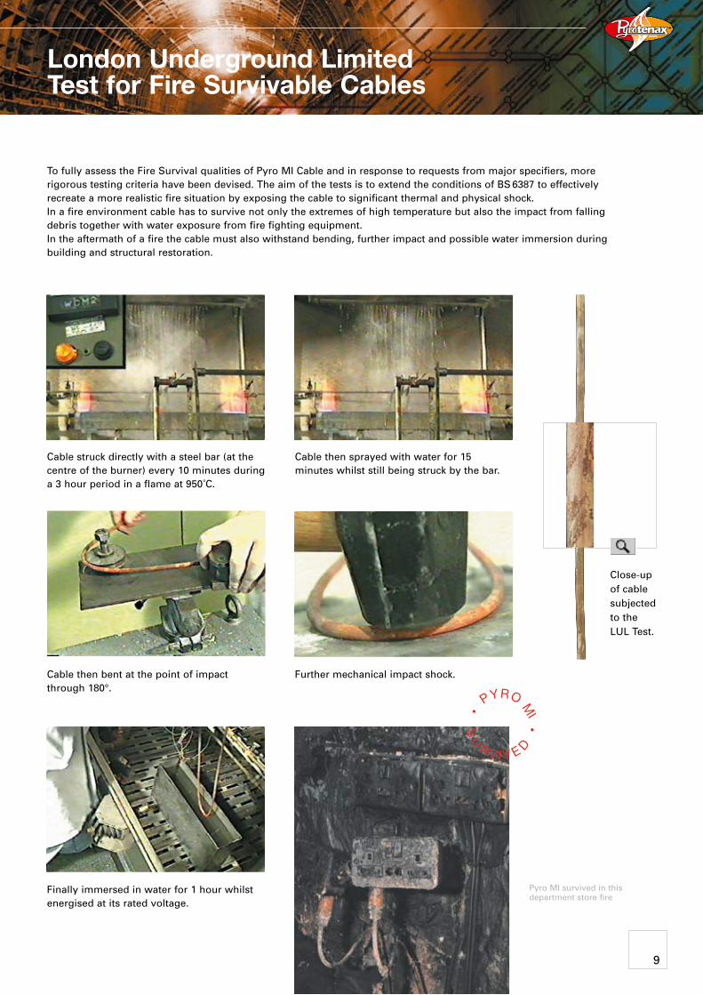
Cable struck directly with a steel bar (at the centre of the burner) every 10 minutes during a 3 hour period in a flame at 950˚C.
Cable then sprayed with water for 15 minutes whilst still being struck by the bar.
Cable then bent at the point of impact through 180°.
Finally immersed in water for 1 hour whilst energised at its rated voltage.
Further mechanical impact shock.
London Underground Limited Test for Fire Survivable Cables
To fully assess the Fire Survival qualities of Pyro MI Cable and in response to requests from major specifiers, more rigorous testing criteria have been devised. The aim of the tests is to extend the conditions of BS 6387 to effectively recreate a more realistic fire situation by exposing the cable to significant thermal and physical shock. In a fire environment cable has to survive not only the extremes of high temperature but also the impact from falling debris together with water exposure from fire fighting equipment. In the aftermath of a fire the cable must also withstand bending, further impact and possible water immersion during building and structural restoration.
Pyro MI survived in this department store fire
Close-up of cable subjected to the LUL Test.
9
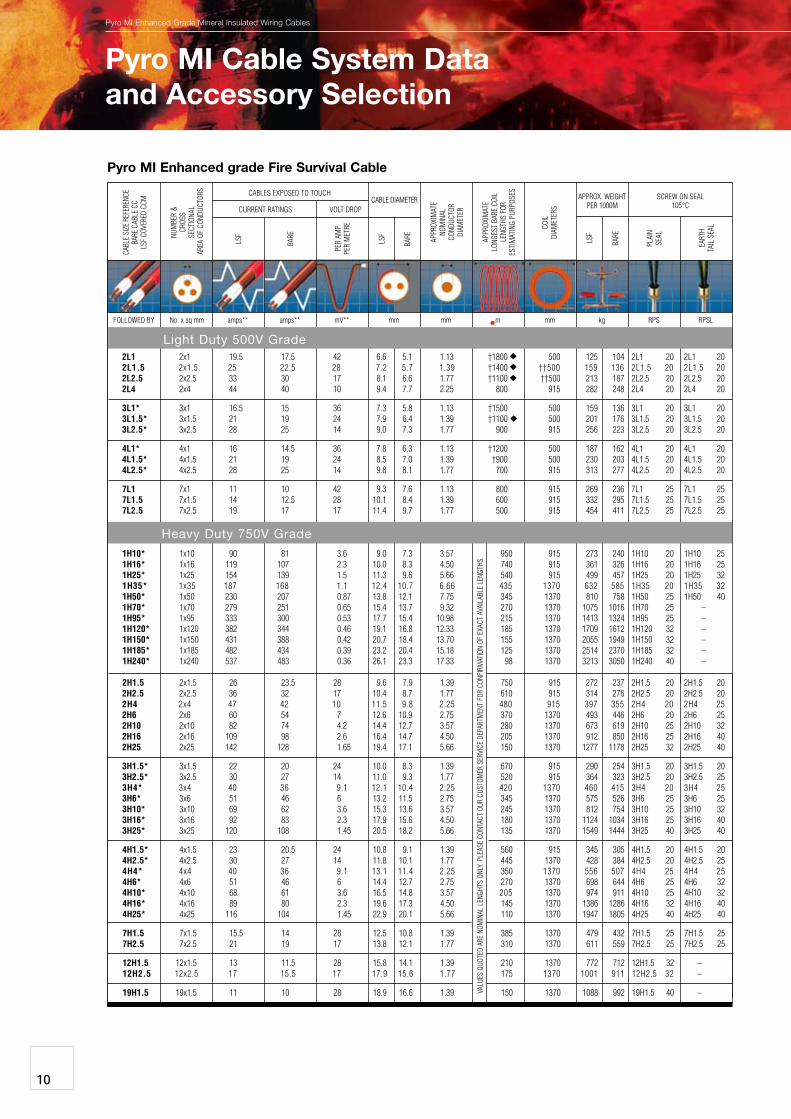
Pyro MI Enhanced grade Fire Survival Cable
pyro MI Enhanced Grade Mineral Insulated Wiring cables
COIL
DIAM
ETER
S
FOLLOWED BY No. x sq mm amps** amps** mV** mm mm m mm kg RPS RPSL
2L1 2x1 19.5 17.5 42 6.6 5.1 1.13 †1800 500 125 104 2L1 20 2L1 20 2L1.5 2x1.5 25 22.5 28 7.2 5.7 1.39 †1400 ††500 159 136 2L1.5 20 2L1.5 20 2L2.5 2x2.5 33 30 17 8.1 6.6 1.77 †1100 ††500 213 187 2L2.5 20 2L2.5 20 2L4 2x4 44 40 10 9.4 7.7 2.25 800 915 282 248 2L4 20 2L4 20
3L1* 3x1 16.5 15 36 7.3 5.8 1.13 †1500 500 159 136 3L1 20 3L1 20 3L1.5* 3x1.5 21 19 24 7.9 6.4 1.39 †1100 500 201 176 3L1.5 20 3L1.5 20 3L2.5* 3x2.5 28 25 14 9.0 7.3 1.77 900 915 256 223 3L2.5 20 3L2.5 20
4L1* 4x1 16 14.5 36 7.8 6.3 1.13 †1200 500 187 162 4L1 20 4L1 20 4L1.5* 4x1.5 21 19 24 8.5 7.0 1.39 †900 500 230 203 4L1.5 20 4L1.5 20 4L2.5* 4x2.5 28 25 14 9.8 8.1 1.77 700 915 313 277 4L2.5 20 4L2.5 20
7L1 7x1 11 10 42 9.3 7.6 1.13 800 915 269 236 7L1 25 7L1 25 7L1.5 7x1.5 14 12.5 28 10.1 8.4 1.39 600 915 332 295 7L1.5 25 7L1.5 25 7L2.5 7x2.5 19 17 17 11.4 9.7 1.77 500 915 454 411 7L2.5 25 7L2.5 25
1H10* 1x10 90 81 3.6 9.0 7.3 3.57 950 915 273 240 1H10 20 1H10 25 1H16* 1x16 119 107 2.3 10.0 8.3 4.50 740 915 361 326 1H16 20 1H16 25 1H25* 1x25 154 139 1.5 11.3 9.6 5.66 540 915 499 457 1H25 20 1H25 32 1H35* 1x35 187 168 1.1 12.4 10.7 6.66 435 1370 632 585 1H35 20 1H35 32 1H50* 1x50 230 207 0.87 13.8 12.1 7.75 345 1370 810 758 1H50 25 1H50 40 1H70* 1x70 279 251 0.65 15.4 13.7 9.32 270 1370 1075 1016 1H70 25 – 1H95* 1x95 333 300 0.53 17.7 15.4 10.98 215 1370 1413 1324 1H95 25 – 1H120* 1x120 382 344 0.46 19.1 16.8 12.33 185 1370 1709 1612 1H120 32 – 1H150* 1x150 431 388 0.42 20.7 18.4 13.70 155 1370 2055 1949 1H150 32 – 1H185* 1x185 482 434 0.39 23.2 20.4 15.18 125 1370 2514 2370 1H185 32 – 1H240* 1x240 537 483 0.36 26.1 23.3 17.33 98 1370 3213 3050 1H240 40 – 2H1.5 2x1.5 26 23.5 28 9.6 7.9 1.39 750 915 272 237 2H1.5 20 2H1.5 20 2H2.5 2x2.5 36 32 17 10.4 8.7 1.77 610 915 314 276 2H2.5 20 2H2.5 20 2H4 2x4 47 42 10 11.5 9.8 2.25 480 915 397 355 2H4 20 2H4 25 2H6 2x6 60 54 7 12.6 10.9 2.75 370 1370 493 446 2H6 20 2H6 25 2H10 2x10 82 74 4.2 14.4 12.7 3.57 280 1370 673 619 2H10 25 2H10 32 2H16 2x16 109 98 2.6 16.4 14.7 4.50 205 1370 912 850 2H16 25 2H16 40 2H25 2x25 142 128 1.65 19.4 17.1 5.66 150 1370 1277 1178 2H25 32 2H25 40
3H1.5* 3x1.5 22 20 24 10.0 8.3 1.39 670 915 290 254 3H1.5 20 3H1.5 20 3H2.5* 3x2.5 30 27 14 11.0 9.3 1.77 520 915 364 323 3H2.5 20 3H2.5 25 3H4* 3x4 40 36 9.1 12.1 10.4 2.25 420 1370 460 415 3H4 20 3H4 25 3H6* 3x6 51 46 6 13.2 11.5 2.75 345 1370 575 526 3H6 25 3H6 25 3H10* 3x10 69 62 3.6 15.3 13.6 3.57 245 1370 812 754 3H10 25 3H10 32 3H16* 3x16 92 83 2.3 17.9 15.6 4.50 180 1370 1124 1034 3H16 25 3H16 40 3H25* 3x25 120 108 1.45 20.5 18.2 5.66 135 1370 1549 1444 3H25 40 3H25 40
4H1.5* 4x1.5 23 20.5 24 10.8 9.1 1.39 560 915 345 305 4H1.5 20 4H1.5 20 4H2.5* 4x2.5 30 27 14 11.8 10.1 1.77 445 1370 428 384 4H2.5 20 4H2.5 25 4H4* 4x4 40 36 9.1 13.1 11.4 2.25 350 1370 556 507 4H4 25 4H4 25 4H6* 4x6 51 46 6 14.4 12.7 2.75 270 1370 698 644 4H6 25 4H6 32 4H10* 4x10 68 61 3.6 16.5 14.8 3.57 205 1370 974 911 4H10 25 4H10 32 4H16* 4x16 89 80 2.3 19.6 17.3 4.50 145 1370 1386 1286 4H16 32 4H16 40 4H25* 4x25 116 104 1.45 22.9 20.1 5.66 110 1370 1947 1805 4H25 40 4H25 40
7H1.5 7x1.5 15.5 14 28 12.5 10.8 1.39 385 1370 479 432 7H1.5 25 7H1.5 25 7H2.5 7x2.5 21 19 17 13.8 12.1 1.77 310 1370 611 559 7H2.5 25 7H2.5 25
12H1.5 12x1.5 13 11.5 28 15.8 14.1 1.39 210 1370 772 712 12H1.5 32 – 12H2.5 12x2.5 17 15.5 17 17.9 15.6 1.77 175 1370 1001 911 12H2.5 32 –
19H1.5 19x1.5 11 10 28 18.9 16.6 1.39 150 1370 1088 992 19H1.5 40 –
BARE
LSF
LSF
BARE
CABL
E SI
ZE R
EFER
ENCE
BARE
CAB
LE C
CLS
F CO
VERE
D CC
M
NUM
BER
&
CROS
S SE
CTIO
NAL
ARE
A OF
CON
DUCT
ORS
APPR
OXIM
ATE
NOM
INAL
CO
NDUC
TOR
DIAM
ETER
APPR
OXIM
ATE
LONG
EST
BARE
COI
L LE
NGTH
S FO
R ES
TIM
ATIN
G PU
RPOS
ES APPROX. WEIGHT PER 1000M
CABLE DIAMETER SCREW ON SEAL105°C
PLAI
N SE
AL
EART
H TA
IL S
EAL
LSF
BARE
PER
AMP
PER
MET
RE
CABLES EXPOSED TO TOUCH
CURRENT RATINGS VOLT DROP
•
VALU
ES q
UOTE
D AR
E NO
MIN
AL L
ENGH
TS O
NLY.
PLE
ASE
CONT
ACT
OUR
CUST
OMER
SER
VICE
DEP
ARTM
ENT
FOR
CONF
IRM
ATIO
N OF
EXA
CT A
VAIL
ABLE
LEN
GTHS
.
Pyro MI Cable System Dataand Accessory Selection
10
Light Duty 500V Grade
Heavy Duty 750V Grade
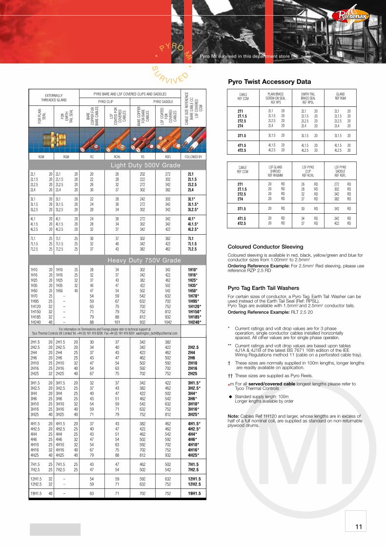
Pyro Twist Accessory Data
MI
Coloured Conductor Sleevingcoloured sleeving is available in red, black, yellow/green and blue for conductor sizes from 1.00mm2 to 2.5mm2
Ordering Reference Example: For 2.5mm2 red sleeving, please use reference rZp 2.5 rd
Pyro Tag Earth Tail Washers
For certain sizes of conductor, a pyro tag Earth tail Washer can be used instead of the Earth tail seal (ref: rpsL). pyro tags are available with 1.5mm2 and 2.5mm2 conductor tails.Ordering Reference Example: rLt 2.5 20
* current ratings and volt drop values are for 3 phase operation, single conductor cables installed horizontally spaced. All other values are for single phase operation.
** current ratings and volt drop values are based upon tables 4J1A & 4J1B of the latest Bs 7671 16th edition of the IEE Wiring regulations method 11 (cable on a perforated cable tray).
† these sizes are normally supplied in 100m lengths, longer lengths are readily available on application.
†† these sizes are supplied as pyro reels.
•m For all served/covered cable longest lengths please refer to tyco thermal controls
standard supply length: 100m Longer lengths available by order
Note: cables ref 1H120 and larger, whose lengths are in excess of half of a full nominal coil, are supplied as standard on non-returnable plywood drums.
CABLE REF CCM
2T12T.1.52T2.52T4
3T1.5
4T1.54T2.5
2L1 202L1.5 202L2.5 202L4 20
3L1.5 20
4L1.5 204L2.5 20
2L1 202L1.5 202L2.5 202L4 20
3L1.5 20
4L1.5 204L2.5 20
2L1 202L1.5 202L2.5 202L4 20
3L1.5 20
4L1.5 204L2.5 20
PLAIN BRASS SCREW-ON SEAL
REF RPS
EARTH TAIL BRASS SEAL
REF RPSL
GLAND REF RGM
CABLE REF CCM
LSF GLANDSHROUD
REF RHGMM
LSF PYROCLIP
REF RCHL
2T12T.1.52T2.52T4
3T1.5
4T1.54T2.5
20 RD20 RD20 RD20 RD
20 RD 20 RD20 RD
26 RD28 RD32 RD37 RD
30 RD
34 RD37 RD
272 RD302 RD342 RD382 RD
342 RD
342 RD422 RD
LSF PYROSADDLE
REF RSFL
CABL
E SI
ZE R
EFER
ENCE
BARE
CAB
LE C
CLS
F CO
VERE
D C
CM
LSF
COAT
ED
FOR
COVE
RED
CABL
ES
BARE
CO
PPER
FOR
BA
RE C
ABLE
S
FOR
PLAI
N SE
AL
FOR
EART
H TA
IL S
EAL
LSF
COAT
ED F
OR
COVE
RED
CABL
ES
BARE
COP
PER
FOR
BARE
CA
BLES
PYRO BARE AND LSF COVERED CLIPS AND SADDLES
PYRO CLIP PYRO SADDLE
EXTERNALLY THREADED GLAND
For information on Terminations and Fixings please refer to technical support at Tyco Thermal Controls UK Limited Tel: +44 (0) 191 419 8200 Fax:+44 (0) 191 419 8201 [email protected]
RC RCHL RS RSFL FOLLOWED BY
2L1 20 2L1 20 20 26 202 272 2L1 2L1.5 20 2L1.5 20 22 28 222 302 2L1.5 2L2.5 20 2L2.5 20 26 32 272 342 2L2.5 2L4 20 2L4 20 30 37 302 382 2L4
3L1 20 3L1 20 22 28 242 302 3L1* 3L1.5 20 3L1.5 20 24 30 272 342 3L1.5* 3L2.5 20 3L2.5 20 28 34 302 342 3L2.5*
4L1 20 4L1 20 24 30 272 342 4L1* 4L1.5 20 4L1.5 20 28 34 302 342 4L1.5* 4L2.5 20 4L2.5 20 32 37 342 422 4L2.5*
7L1 25 7L1 25 30 37 302 382 7L1 7L1.5 25 7L1.5 25 32 40 342 422 7L1.5 7L2.5 25 7L2.5 25 37 43 382 462 7L2.5
1H10 20 1H10 25 28 34 302 342 1H10* 1H16 20 1H16 25 32 37 342 422 1H16* 1H25 20 1H25 32 37 43 382 462 1H25* 1H35 20 1H35 32 40 47 422 502 1H35* 1H50 25 1H50 40 47 54 502 542 1H50* 1H70 25 – 54 59 542 632 1H70* 1H95 25 – 59 67 632 702 1H95* 1H120 32 – 63 75 702 752 1H120* 1H150 32 – 71 79 752 812 1H150* 1H185 32 – 79 88 812 932 1H185* 1H240 40 – 88 101 932 1042 1H240*
2H1.5 20 2H1.5 20 30 37 342 382 2H2.5 20 2H2.5 20 34 40 342 422 2H2.5 2H4 20 2H4 25 37 43 422 462 2H4 2H6 20 2H6 25 43 47 462 502 2H6 2H10 25 2H10 32 47 54 502 592 2H10 2H16 25 2H16 40 54 63 592 702 2H16 2H25 32 2H25 40 67 75 702 752 2H25
3H1.5 20 3H1.5 20 32 37 342 422 3H1.5* 3H2.5 20 3H2.5 25 37 43 382 462 3H2.5* 3H4 20 3H4 25 40 47 422 502 3H4* 3H6 25 3H6 25 43 51 462 542 3H6* 3H10 25 3H10 32 54 59 542 632 3H10* 3H16 25 3H16 40 59 71 632 752 3H16* 3H25 40 3H25 40 71 79 752 812 3H25*
4H1.5 20 4H1.5 20 37 43 382 462 4H1.5* 4H2.5 20 4H2.5 25 40 47 422 462 4H2.5* 4H4 25 4H4 25 43 51 462 542 4H4* 4H6 25 4H6 32 47 54 502 592 4H6* 4H10 25 4H10 32 54 63 592 702 4H10* 4H16 32 4H16 40 67 75 702 752 4H16* 4H25 40 4H25 40 79 88 812 932 4H25*
7H1.5 25 7H1.5 25 43 47 462 502 7H1.5 7H2.5 25 7H2.5 25 47 54 502 542 7H2.5
12H1.5 32 – 54 59 592 632 12H1.5 12H2.5 32 – 59 71 632 752 12H2.5
19H1.5 40 – 63 71 702 752 19H1.5
Light Duty 500V Grade
Heavy Duty 750V Grade
Pyro MI survived in this department store fire
RGM RGM RC RCHL RS RSFL FOLLOWED BY
11
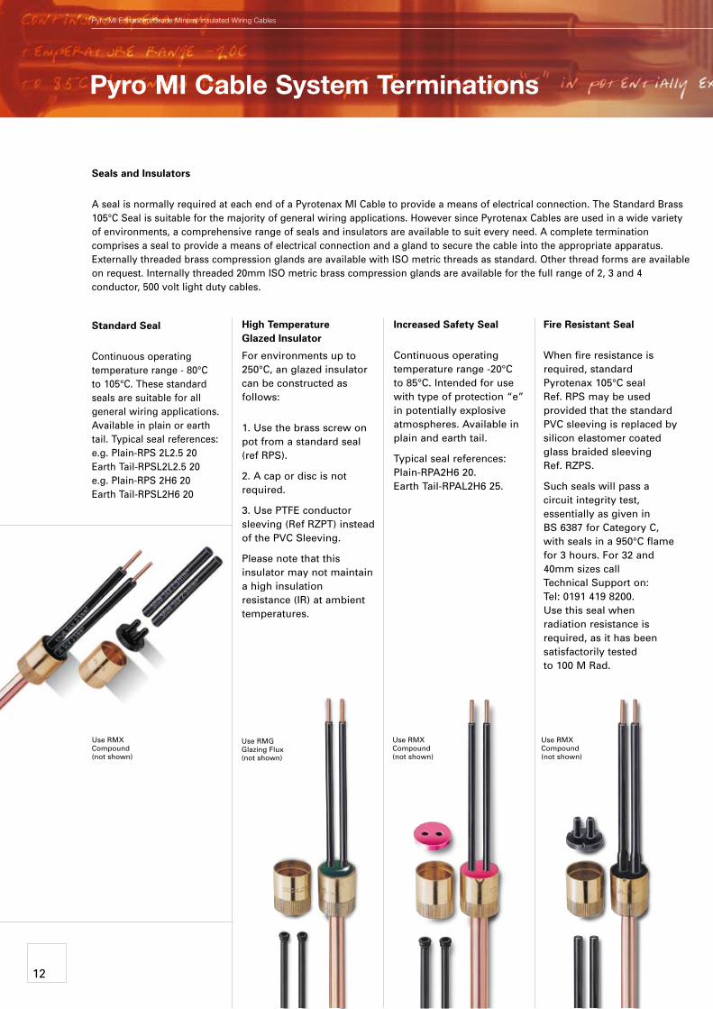
Fire Resistant Seal
When fire resistance is required, standard Pyrotenax 105°C seal Ref. RPS may be used provided that the standard PVC sleeving is replaced by silicon elastomer coated glass braided sleeving Ref. RZPS.
Such seals will pass a circuit integrity test, essentially as given in BS 6387 for Category C, with seals in a 950°C flame for 3 hours. For 32 and 40mm sizes call Technical Support on: Tel: 0191 419 8200. Use this seal when radiation resistance is required, as it has been satisfactorily tested to 100 M Rad.
Increased Safety Seal
Continuous operating temperature range -20°C to 85°C. Intended for use with type of protection “e” in potentially explosive atmospheres. Available in plain and earth tail.
Typical seal references: Plain-RPA2H6 20. Earth Tail-RPAL2H6 25.
High Temperature Glazed Insulator
For environments up to 250°C, an glazed insulator can be constructed as follows:
1. Use the brass screw on pot from a standard seal (ref RPS).
2. A cap or disc is not required.
3. Use PTFE conductor sleeving (Ref RZPT) instead of the PVC Sleeving.
Please note that this insulator may not maintain a high insulation resistance (IR) at ambient temperatures.
Standard Seal
Continuous operating temperature range - 80°C to 105°C. These standard seals are suitable for all general wiring applications. Available in plain or earth tail. Typical seal references: e.g. Plain-RPS 2L2.5 20 Earth Tail-RPSL2L2.5 20 e.g. Plain-RPS 2H6 20 Earth Tail-RPSL2H6 20
Use RMG Glazing Flux (not shown)
Use RMX Compound (not shown)
Use RMX Compound (not shown)
Pyro MI Cable System Terminations
Use RMX Compound (not shown)
pyro MI Enhanced Grade Mineral Insulated Wiring cables
Seals and Insulators
A seal is normally required at each end of a Pyrotenax MI Cable to provide a means of electrical connection. The Standard Brass 105°C Seal is suitable for the majority of general wiring applications. However since Pyrotenax Cables are used in a wide variety of environments, a comprehensive range of seals and insulators are available to suit every need. A complete termination comprises a seal to provide a means of electrical connection and a gland to secure the cable into the appropriate apparatus. Externally threaded brass compression glands are available with ISO metric threads as standard. Other thread forms are available on request. Internally threaded 20mm ISO metric brass compression glands are available for the full range of 2, 3 and 4 conductor, 500 volt light duty cables.
12
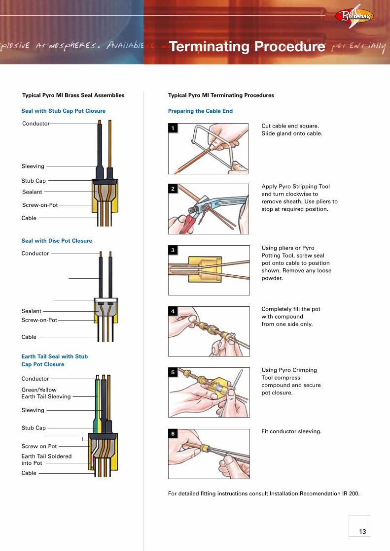
Seal with Stub Cap Pot Closure
Seal with Disc Pot Closure
Earth Tail Seal with Stub Cap Pot Closure
Conductor
Stub Cap
Screw-on-Pot
Sleeving
Cable
Sealant
Conductor
Conductor
Green/Yellow Earth Tail Sleeving
Sleeving
Stub Cap
Screw on Pot
Cable
Earth Tail Soldered into Pot
Screw-on-Pot
Cable
Sealant
Typical Pyro MI Brass Seal Assemblies Typical Pyro MI Terminating Procedures
Using pliers or Pyro Potting Tool, screw seal pot onto cable to position shown. Remove any loose powder.
Cut cable end square. Slide gland onto cable.
Completely fill the pot with compound from one side only.
Using Pyro Crimping Tool compress compound and secure pot closure.
Fit conductor sleeving.
Apply Pyro Stripping Tool and turn clockwise to remove sheath. Use pliers to stop at required position.
For detailed fitting instructions consult Installation Recomendation IR 200.
3
Preparing the Cable End
1
2
4
5
6
Terminating Procedure
13
Pyro MI Cable Fixings
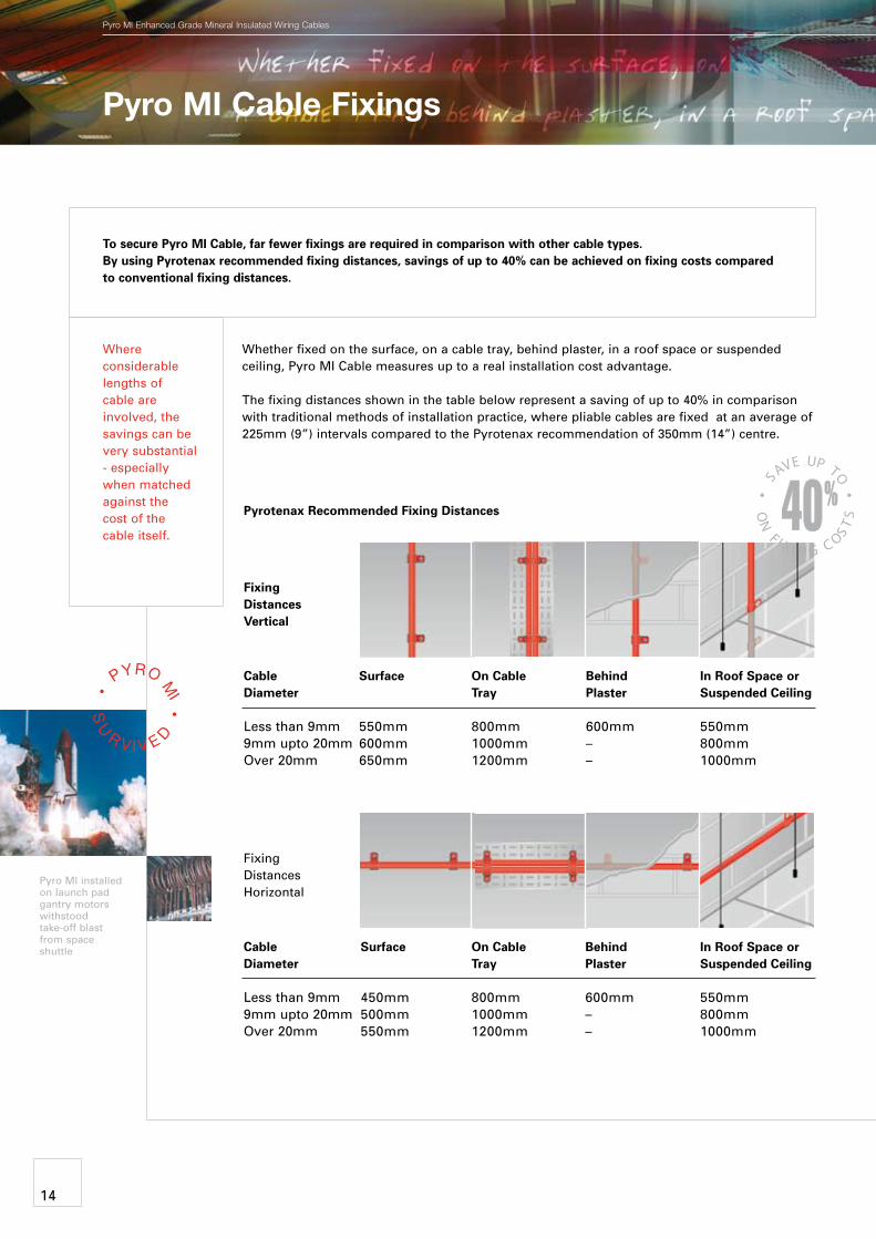
Surface
450mm 500mm 550mm
On Cable Tray
800mm 1000mm 1200mm
Behind Plaster
600mm – –
In Roof Space orSuspended Ceiling
550mm 800mm 1000mm
On Cable Tray
800mm 1000mm 1200mm
Behind Plaster
600mm – –
In Roof Space orSuspended Ceiling
550mm 800mm 1000mm
pyro MI Enhanced Grade Mineral Insulated Wiring cables
Where considerable lengths of cable are involved, the savings can be very substantial - especially when matched against the cost of the cable itself.
Whether fixed on the surface, on a cable tray, behind plaster, in a roof space or suspended ceiling, Pyro MI Cable measures up to a real installation cost advantage.
The fixing distances shown in the table below represent a saving of up to 40% in comparison with traditional methods of installation practice, where pliable cables are fixed at an average of 225mm (9”) intervals compared to the Pyrotenax recommendation of 350mm (14”) centre.
Fixing Distances Vertical
Cable Diameter
Less than 9mm 9mm upto 20mm Over 20mm
Fixing Distances Horizontal
Cable Diameter
Less than 9mm 9mm upto 20mm Over 20mm
Pyrotenax Recommended Fixing Distances
To secure Pyro MI Cable, far fewer fixings are required in comparison with other cable types. By using Pyrotenax recommended fixing distances, savings of up to 40% can be achieved on fixing costs compared to conventional fixing distances.
Pyro MI installed on launch pad gantry motors withstood take-off blast from space shuttle
Surface
550mm 600mm 650mm
14
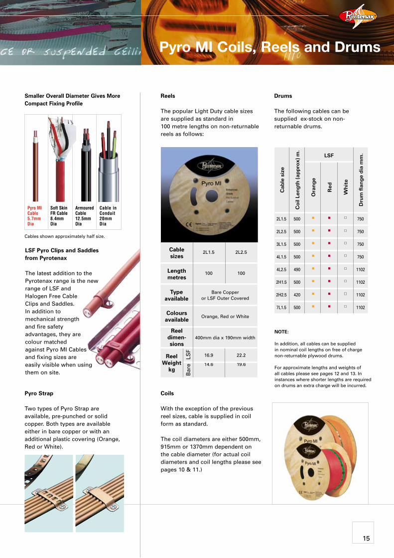
Red
2L1.5
2L2.5
3L1.5
4L1.5
4L2.5
2H1.5
2H2.5
7L1.5
500
500
500
500
490
500
420
500
n
n
n
n
n
n
n
n
n
n
n
n
n
n
n
n
750
750
750
750
1102
1102
1102
1102
Cab
le s
ize
Coi
l Len
gth
(app
rox)
m.
Ora
nge
Whi
te
LSF
Dru
m f
lang
e di
a m
m.
NOTE:
In addition, all cables can be supplied in nominal coil lengths on free of charge non-returnable plywood drums.
For approximate lengths and weights of all cables please see pages 12 and 13. In instances where shorter lengths are required on drums an extra charge will be incurred.
400mm dia x 190mm width
Cable sizes
Length metres
Type available
Colours available
Reel dimen-sions
Reel Weight
kg
2L1.5 2L2.5
100 100
16.9 22.2
14.6 19.6
Bare Copper or LSF Outer Covered
Orange, Red or White
LS
FB
are
Cables shown approximately half size.
Smaller Overall Diameter Gives More Compact Fixing Profile
Pyro MI Coils, Reels and Drums
Reels
The popular Light Duty cable sizes are supplied as standard in 100 metre lengths on non-returnable reels as follows:
Coils
With the exception of the previous reel sizes, cable is supplied in coil form as standard.
The coil diameters are either 500mm, 915mm or 1370mm dependent on the cable diameter (for actual coil diameters and coil lengths please see pages 10 & 11.)
Drums
The following cables can be supplied ex-stock on non- returnable drums.
Pyro MI Cable5.7mm Dia
Soft Skin FR Cable8.4mm Dia
Armoured Cable12.5mm Dia
Cable inConduit20mm Dia
Pyro Strap
Two types of Pyro Strap are available, pre-punched or solid copper. Both types are available either in bare copper or with an additional plastic covering (Orange, Red or White).
LSF Pyro Clips and Saddles from Pyrotenax
The latest addition to the Pyrotenax range is the new range of LSF and Halogen Free Cable Clips and Saddles. In addition to mechanical strength and fire safety advantages, they are colour matched against Pyro MI Cables and fixing sizes are easily visible when using them on site.
15
p r o d u c t s
world classOffices, Distribution Centres and Associated Agents World Wide
www.tycothermal.com
Pyrotenax, Pyro MI and Pyro FR-s are trademark of Tyco Thermal Controls LLC and its affiliates in designated countries
All of the information contained in this publication , including illustrations, is believed to be reliable. Users however, should independently evaluate the suitability of each product for their application. Tyco Thermal Controls makes no warranties as to the accuracy or completeness of the information and disclaims any liability regarding it’s use. Tyco Thermal Control’s only obligations are those in the Standard Terms and Conditions of Sale for this product and in no case will Tyco Thermal Controls be liable for any incidental, indirect or consequential damages arising from the sale, resale, use or misuse of the product. Tyco Thermal Controls Specifications are subject to change without notice. In addition Tyco Thermal Controls reserves the right to make changes in materials or processing, without notification to the buyer, which do not affect compliance with any applicable cable specification. This document was supplied to you by:
Our products satisfy the requirements of the relevant European Directives.
pyro MI Enhanced Grade Mineral Insulated Wiring cables
www.pyrotenax.co.uk
United KingdomTyco Thermal Controls UK Ltd3 Rutherford Road, Stephenson Industrial EstateWashington, Tyne & Wear NE37 3HXTel: 0808 178 1858Fax: 0808 178 [email protected]
Irelandfree phone 1800 654 241free fax 1800 654 [email protected]
European Headquarters Tyco Thermal ControlsRomeinse Straat 143001 LeuvenBelgiumTel. (32) 16 213 511Fax (32) 16 213 610
Asia/Middle East Tyco Thermal Controls1st Floor, Ujagar Compound,Sub Plot 2A, CTS No. 653/6,Opp. Deonar Bus Depot,Deonar, Mumbai400 088 IndiaTel: 91-22-2550 9890/91/92/...98Fax: 91-22-2556 1491
Australia/New ZealandTyco Thermal Controlsc/- Goyen Controls Co Pty Ltd268 Milperra RoadMilperra NSW 2214AustraliaTel. +61 2 9792 02 79Fax +61 2 9792 0224
LPCB Certificate no. 063
© 2
004
Tyc
o T
herm
al C
ontr
ols
CD
E-0
801
Rev
.6
04/1
0 P
rinte
d in
Bel
gium
on
chlo
rine-
free
ble
ache
d pa
per.