Embed Size (px)
Citation preview
Work of IMPAC Infrared GmbH
Non-Contact Thermometry
Pyrometer-Pyrometer-HandbookHandbook
Få mere information ominfrarød måleteknik og
pyrometre på vor hjemmesidewww.contika/pyrometer/
1Pyrometer Handbook
Pyrometer-Handbook
Work of IMPAC Infrared GmbH
2 Pyrometer Handbook
Publication Data
© Copyright IMPAC Infrared GmbH 2004
All rights reserved. No part of this handbook may be copied, duplicated ortranslated into any other language without prior written consent ofIMPAC Infrared GmbH.
Publisher: IMPAC Infrared GmbHKrifteler Str. 3260326 Frankfurt am MainGermany
Authors: Collective of authors, IMPAC Infrared GmbH
Illustrations: All images IMPAC
3Pyrometer Handbook
Foreword
Pyrometry, being part of a highly specialised field ofmeasuring techniques, has developed a certain mysteriousaura about it. This mystery stems from the false perceptionthat the technique is difficult to master. In fact, pyrometersare easy to operate in industrial applications so long as thebasic principles are known and observed. Unfortunately, inthe past these principles have not always been fully taken intoaccount, especially when low-cost pyrometers and IR sensorshave been offered by mail order.This handbook was created with the intent to reassure theuser, and thus instill in him or her the confidence to usepyrometric measurement.
The knowledge and experience of many specialists in thefield of non-contact temperature measurement has beenbrought into play. We thank all those who have contributedtheir expertise to this handbook. We have attempted toincorporate their suggestions and critiques, and we hope thatwe have succeeded in presenting pyrometry in such a way asto convey its simplicity.

4 Pyrometer Handbook
5Pyrometer Handbook
Table of Contents
1. What is Pyrometry ? . . . . . . . . . . . . . . . . . . . . . . . . . . . 7
2. Physical Principles . . . . . . . . . . . . . . . . . . . . . . . . . . . .12
3. Properties of Real Objects . . . . . . . . . . . . . . . . . . . . . .16
4. Emissivity of Various Materials . . . . . . . . . . . . . . . . . .19
5. Determining Emissivity . . . . . . . . . . . . . . . . . . . . . . . .23
6. Choosing the spectral range . . . . . . . . . . . . . . . . . . . . .24
6.1 Emissivity Errors . . . . . . . . . . . . . . . . . . . . . . . . . .24
6.2 Atmospheric Windows . . . . . . . . . . . . . . . . . . . . . .27
7. Spot Size and Measuring Distance . . . . . . . . . . . . . . . .29
8. The Pyrometer . . . . . . . . . . . . . . . . . . . . . . . . . . . . . . . .32
8.1 Construction and Function . . . . . . . . . . . . . . . . . . .32
8.2 Pyrometer Types . . . . . . . . . . . . . . . . . . . . . . . . . .33
9. Digital Pyrometers . . . . . . . . . . . . . . . . . . . . . . . . . . . .37
10. Fibre Optic Pyrometers . . . . . . . . . . . . . . . . . . . . . . . . .41
11. Sighting and Viewing Devices . . . . . . . . . . . . . . . . . . .44
12. Linearisation . . . . . . . . . . . . . . . . . . . . . . . . . . . . . . . . .45
13. Calibration . . . . . . . . . . . . . . . . . . . . . . . . . . . . . . . . . . .46
14. Optics, Lenses, Window Material . . . . . . . . . . . . . . . . .47
15. Sources of Interference . . . . . . . . . . . . . . . . . . . . . . . . .50
16. Accesories . . . . . . . . . . . . . . . . . . . . . . . . . . . . . . . . . . .55
Bibliography and Reading List . . . . . . . . . . . . . . . . . . . . . .57
Tables . . . . . . . . . . . . . . . . . . . . . . . . . . . . . . . . . . . . . . . . . .59
Terminology . . . . . . . . . . . . . . . . . . . . . . . . . . . . . . . . . . . . .63
Index . . . . . . . . . . . . . . . . . . . . . . . . . . . . . . . . . . . . . . . . . .71

Pyrometer Handbook
What is Pyrometry ?
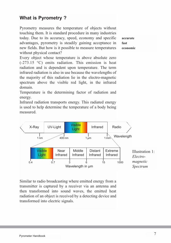
Pyrometry measures the temperature of objects withouttouching them. It is standard procedure in many industriestoday. Due to its accuracy, speed, economy and specificadvantages, pyrometry is steadily gaining acceptance innew fields. But how is it possible to measure temperatureswithout physical contact?Every object whose temperature is above absolute zero(-273.15 °C) emits radiation. This emission is heatradiation and is dependent upon temperature. The terminfrared radiation is also in use because the wavelengths ofthe majority of this radiation lie in the electro-magneticspectrum above the visible red light, in the infrareddomain.Temperature is the determining factor of radiation andenergy.Infrared radiation transports energy. This radiated energyis used to help determine the temperature of a body beingmeasured.
Similar to radio broadcasting where emitted energy from atransmitter is captured by a receiver via an antenna andthen transformed into sound waves, the emitted heatradiation of an object is received by a detecting device andtransformed into electric signals.
UV-Light
7Pyrometer Handbook
Illustration 1:Electro-magneticSpectrum
accuratefasteconomic
RadioX-Ray
1 µm1 nm 1 mm
VisibleLight
3
NearInfrared
MiddleInfrared
DistantInfrared
60.70.4Wavelength in µm
ExtremeInfrared
100015
400 nm Wavelength
InfraredVisibleLight
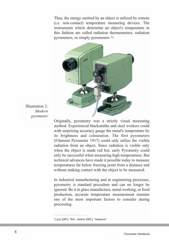
Thus, the energy emitted by an object is utilized by remote(i.e. non-contact) temperature measuring devices. Theinstruments which determine an object's temperature inthis fashion are called radiation thermometers, radiationpyrometers, or simply pyrometers 1).
Originally, pyrometry was a strictly visual measuringmethod. Experienced blacksmiths and steel workers couldwith surprising accuracy gauge the metal's temperature byits brightness and colouration. The first pyrometers(Filament Pyrometer 1917) could only utilize the visibleradiation from an object. Since radiation is visible onlywhen the object is made red hot, early Pyrometry couldonly be successful when measuring high temperatures. Buttechnical advances have made it possible today to measuretemperatures far below freezing point from a distance andwithout making contact with the object to be measured.
In industrial manufacturing and in engineering processes,pyrometry is standard procedure and can no longer beignored. Be it in glass manufacture, metal working, or foodproduction, accurate temperature measurement remainsone of the most important factors to consider duringprocessing.
8 Pyrometer Handbook
Illustration 2:Modern
pyrometer
1) pyr [GR.]: “fire“, metron [GR.]: “measure“
Pyrometry's expanding use is primarily due to itsadvantages vis-a-vis temperature measuring by means ofphysical contact.
The advantages of pyrometers are:
· fast response· no adverse effects on temperatures and materials· measuring moving objects· measuring objects which are difficult to access
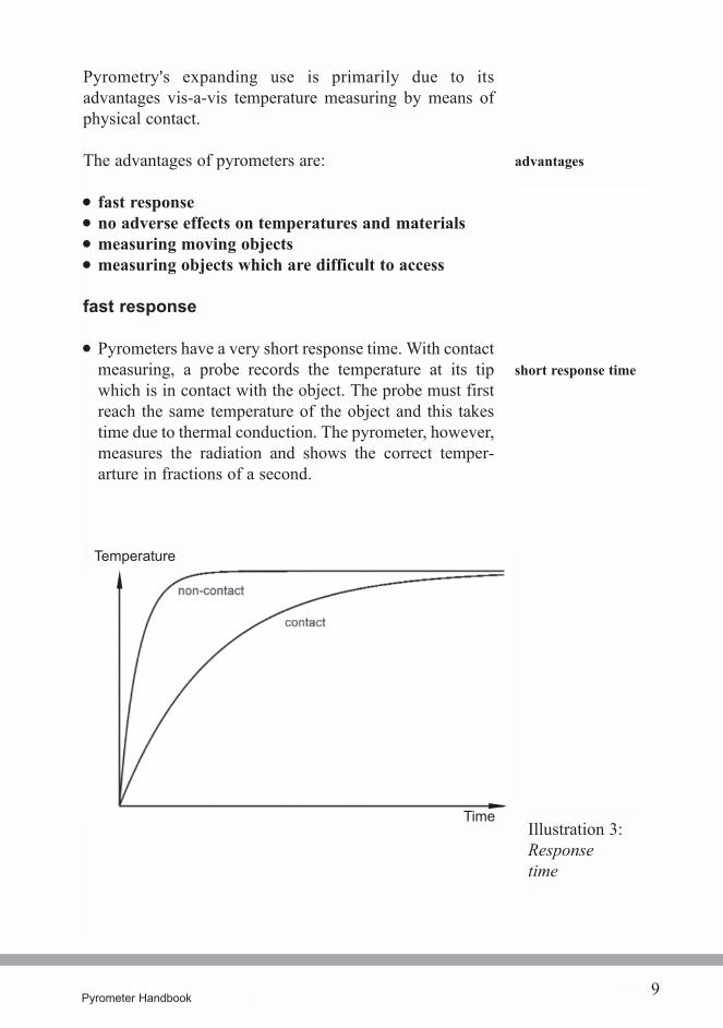
fast response
· Pyrometers have a very short response time. With contactmeasuring, a probe records the temperature at its tipwhich is in contact with the object. The probe must firstreach the same temperature of the object and this takestime due to thermal conduction. The pyrometer, however,measures the radiation and shows the correct temper-arture in fractions of a second.
9Pyrometer Handbook
advantages
short response time
Illustration 3:Responsetime
Time
Temperature
10 Pyrometer Handbook
on material
no adverse effects
· To measure temperature, a radiation pyrometer uses aportion of the energy that is being emitted from theobject anyway. Therefore, the act of measuring itselfdoes not influence the temperature of the object. Acontact thermometer must first reach the temperature ofthe object at the point of contact in order to measure.This process causes heat loss of the object which in turnmay change the temperature at the contact point.
· Using non-contact measuring, sensors cannot bedamaged or destroyed in the same way that can happenwhen using thermocouples and other contact devices.Clearly, the life of contact-free measuring units isconsiderably longer than that of thermo-elements whichare subject to more wear and tear.
measuring moving objects
· Because of the pyrometer's quick response time,temperatures of moving objects can be determinedaccurately
· Contact thermometers can influence temperaturereadings because of friction of the sliding temperatureprobe.
· Measuring by physical contact can also cause scratchingon the measured object's surface.
· Pyrometers do not damage or destroy the measuredobject. Neither drilling nor special fastening to theobject is needed.
measuring objects which are difficult to accessby contact measuring devices
· The optics of pyrometers can be adjusted to measuretemperatures of small objects. Today it is possible toaccurately measure objects with a diameter of 0.2 mm.The measuring error mentioned above (at the contactpoint) is especially great with small objects. Forexample, thin wires.
· High temperatures can be captured easily as there is nodirect contact with the heat source. NiCr-Ni
no scratching onobjects
no damage to themeasured object
on temperatures
small objects
high temperature
Pyrometer Handbook
aggressive materials
inaccessible objects
electricity conductingobjects
poor heat conductorssmall mass, low heat
great distances
viewing windows
thermocouples, for example, change physically at 1300°C and then can no longer achieve repeatable readings.For example, forging steel.
· Highly aggressive materials can be measured withoutcontact and thus without damage to the sensor. Forexample, acids in chemical processes.
· Objects can be measured with pyrometers even thoughthey cannot be physically reached. Pyrometers arecompact units that can be installed nearly anywhere. Allthey need is a clear line of sight to the object.For example, measuring the temperature of metalsduring the heating process.
· Objects conducting electricity may be measured withoutdanger of short-circuiting and without danger to the user.For example, testing the temperature of electric terminalsin switch boxes.
· Heat is transferred very slowly and incompletely to thesensor of a contact measuring instrument from poor heat-conducting objects, from low heat capacity objects andfrom objects which have a small mass. This methodproduces inaccuracies, but they can be eliminated byusing a non-contact device. For example, thin foils andplastic film.
· Great distances are overcome by appropriate optics. Forexample, flare stack monitors.
· It is possible to measure through windows so long as thewindowpane material is compatible 2). For example,measuring temperatures in furnaces and in a vacuum.
11
2) see page 51
12 Pyrometer Handbook
2. Physical Principles
"Someone told me that each equation I included in thebook would halve the sales. I therefore resolved not to haveany equations at all." 3)
We agree with Stephen Hawking's viewpoint. Thosereaders who are interested are encouraged to consult thebibliography and reading list (see page 59).Scientists of the 19th century had already contemplated thephysics of radiation theory. The origins of measuringinfrared radiation lie even further back. In the 17thCentury, Isaac Newton (1642-1727) succeeded in dividingdaylight into its spectral colours by use of a prism. Around1800 Friedrich Wilhelm Herschel (1738-1822) measuredtemperatures of the sun´s spectrum. He found that red lighthas the highest temperature. When he measured theinvisible area beyond the red light he found thetemperature to be even higher than in the red light. Hecalled this the infrared area.
For pyrometry, important correlations were discovered byMax Planck (1858-1947), Wilhelm Wien (1864-1928),Josef Stefan (1835-1893) and Ludwig Boltzmann (1844-1906).Because of their importance, certain laws have been namedafter these scientists. They are briefly explained below.The formulae apply to ideal bodies, so called black bodies.Black bodies are objects which absorb 100 % of allradiation falling on them in all wavelengths.
Newton
Herschel
Planck, Wien,Stefan, Boltzmann
black bodies
3) Stephen W. Hawking, A Brief History of Time, Bantam Press, 1988
13Pyrometer Handbook
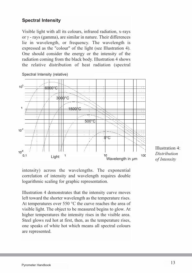
Spectral Intensity
Visible light with all its colours, infrared radiation, x-raysor g - rays (gamma), are similar in nature. Their differenceslie in wavelength, or frequency. The wavelength isexpressed as the "colour" of the light (see Illustration 4).One should consider the energy or the intensity of theradiation coming from the black body. Illustration 4 showsthe relative distribution of heat radiation (spectral
intensity) across the wavelengths. The exponentialcorrelation of intensity and wavelength requires doublelogarithmic scaling for graphic representation.
Illustration 4 demonstrates that the intensity curve movesleft toward the shorter wavelength as the temperature rises.At temperatures over 550 °C the curve reaches the area ofvisible light. The object to be measured begins to glow. Athigher temperatures the intensity rises in the visible area.Steel glows red hot at first, then, as the temperature rises,one speaks of white hot which means all spectral coloursare represented.
6000°C
3000°C
1500°C
500°C
0°C
Illustration 4:Distributionof IntensityLight Wavelength in µm
Spectral Intensity (relative)
14 Pyrometer Handbook
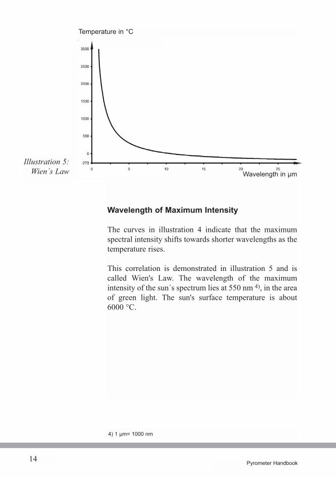
Wavelength of Maximum Intensity
The curves in illustration 4 indicate that the maximumspectral intensity shifts towards shorter wavelengths as thetemperature rises.
This correlation is demonstrated in illustration 5 and iscalled Wien's Law. The wavelength of the maximumintensity of the sun´s spectrum lies at 550 nm 4), in the areaof green light. The sun's surface temperature is about6000 °C.
Illustration 5:Wien´s Law
4) 1 µm= 1000 nm
Temperature in °C
Wavelength in µm
15Pyrometer Handbook
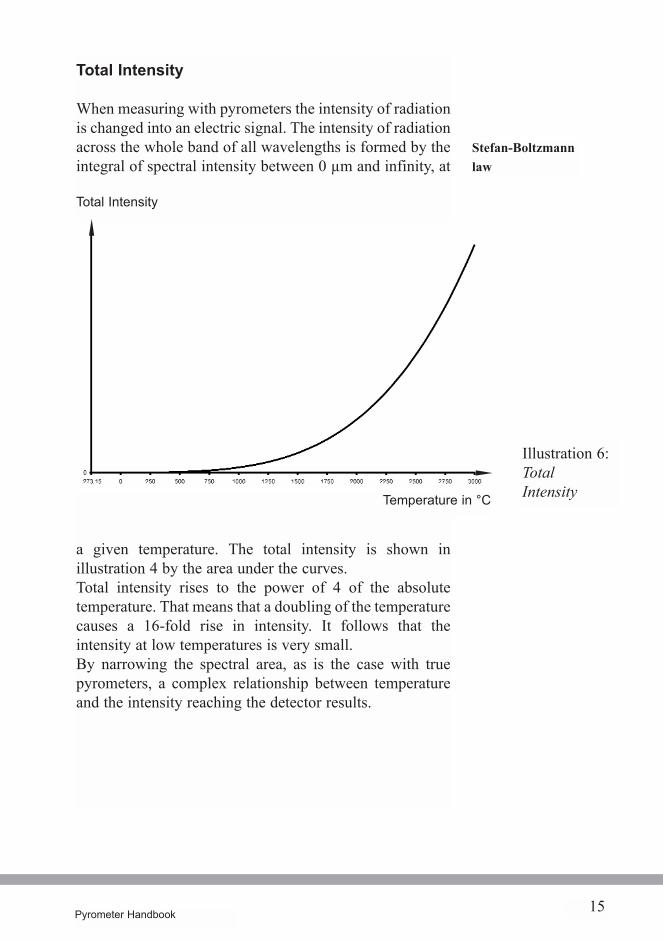
Total Intensity
When measuring with pyrometers the intensity of radiationis changed into an electric signal. The intensity of radiationacross the whole band of all wavelengths is formed by theintegral of spectral intensity between 0 µm and infinity, at
a given temperature. The total intensity is shown inillustration 4 by the area under the curves.Total intensity rises to the power of 4 of the absolutetemperature. That means that a doubling of the temperaturecauses a 16-fold rise in intensity. It follows that theintensity at low temperatures is very small.By narrowing the spectral area, as is the case with truepyrometers, a complex relationship between temperatureand the intensity reaching the detector results.
Illustration 6:TotalIntensity
Stefan-Boltzmannlaw
Total Intensity
Temperature in °C
absorption
16 Pyrometer Handbook
3. Properties of Real Objects
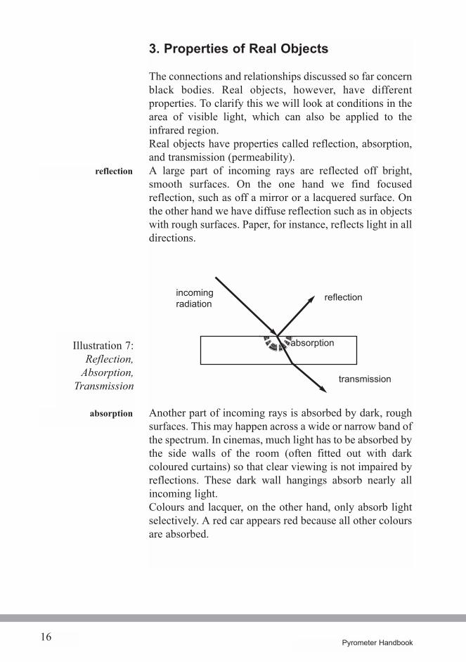
The connections and relationships discussed so far concernblack bodies. Real objects, however, have differentproperties. To clarify this we will look at conditions in thearea of visible light, which can also be applied to theinfrared region.Real objects have properties called reflection, absorption,and transmission (permeability).A large part of incoming rays are reflected off bright,smooth surfaces. On the one hand we find focusedreflection, such as off a mirror or a lacquered surface. Onthe other hand we have diffuse reflection such as in objectswith rough surfaces. Paper, for instance, reflects light in alldirections.
Another part of incoming rays is absorbed by dark, roughsurfaces. This may happen across a wide or narrow band ofthe spectrum. In cinemas, much light has to be absorbed bythe side walls of the room (often fitted out with darkcoloured curtains) so that clear viewing is not impaired byreflections. These dark wall hangings absorb nearly allincoming light.Colours and lacquer, on the other hand, only absorb lightselectively. A red car appears red because all other coloursare absorbed.
reflection
incomingradiation
reflection
transmission
absorptionIllustration 7:Reflection,
Absorption,Transmission
17Pyrometer Handbook
The remaining part of incoming rays penetrate the objectand are transmitted through it. We speak of transparentmaterials. This process too may be selective. While normalwindow glass lets all of the spectrum of visible light passthrough, tinted sunglasses let only a certain part of thespectrum through.
Every object has the above mentioned properties, but theyare represented in different percentages according to thematerial under observation. They are describedmathematically as reflection rate r, absorption rate a, andtransmission rate t. They refer to the ratio of reflected,absorbed, or transmitted intensity to the intensity of theincoming light. The values for r, a and t lie between 0 and15). Their sum is always 1.
With these values a black body's behavior may betheoretically described as one which absorbs all incomingrays. Its absorption coefficient, a, is 1 (one). It followsthen that r = 0 (zero), and t = 0 (zero).
In thermal equilibrium, a body which absorbs well, emitswell. (Robert Kirchhoff, 1824-1877). This means that itsabsorption coefficient a equals its emission coefficient e.At a given temperature maximum flow of radiation comefrom black bodies.Therefore, this object is also called a black body radiationsource. In practical terms this condition is evident in sootor in flat black colour.
The emission coefficient e is the relationship of theemission output of an object to the emission output of ablack body radiation source at the same temperature. e isinfluenced by the object's material and changes with thewavelength, the temperature or other physical values.
transmission
r: reflection ratea: absorption ratet: transmission rate
black bodies
aa = ee
black bodyradiation source
5) one can also say, between 0% and 100%
emissioncoefficient e
18 Pyrometer Handbook
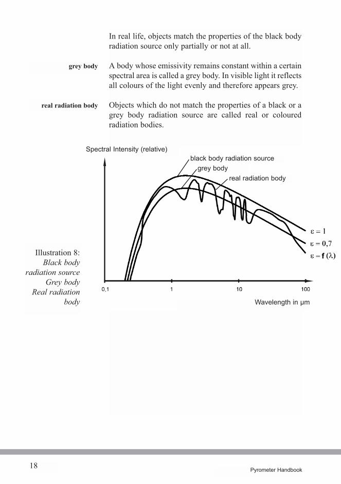
In real life, objects match the properties of the black bodyradiation source only partially or not at all.
A body whose emissivity remains constant within a certainspectral area is called a grey body. In visible light it reflectsall colours of the light evenly and therefore appears grey.
Objects which do not match the properties of a black or agrey body radiation source are called real or colouredradiation bodies.
grey body
Illustration 8:Black body
radiation sourceGrey body
Real radiationbody
real radiation body
black body radiation sourcegrey body
real radiation body
Wavelength in µm
Spectral Intensity (relative)
19Pyrometer Handbook
4. Emissivity of Various Materials
As already described, the emission coefficient e of anobject is the most important value when determining itstemperature with a pyrometer. If one wants to measure thetrue surface temperature of an object with a pyrometer onemust know the emission coefficient, or emissivity, of theobject and enter its value in the pyrometric measuringsystem.
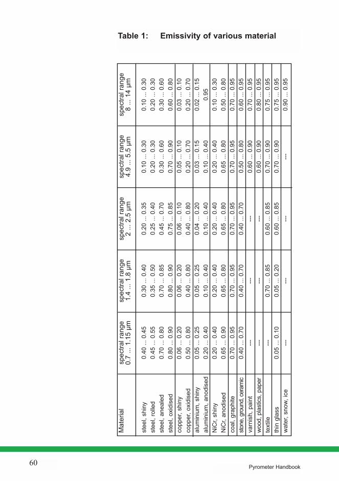
To adjust for the material being measured, pyrometerstherefore have an emissivity setting. The values for thevarious materials may be taken from tables 6). In principle,the emissivity of a material is influenced by wavelength,temperature, etc.
Because the emissivity is dependent upon wavelengthmost materials can be grouped as follows:
1. metals2. non-metals3. transparent materials (opaque)
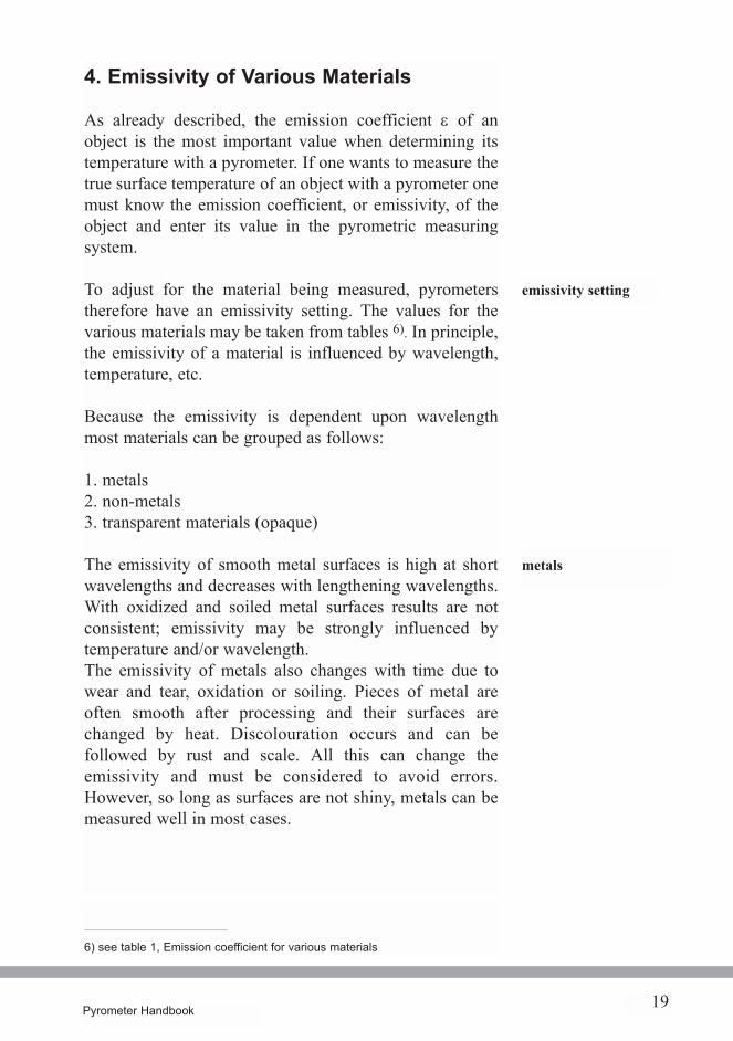
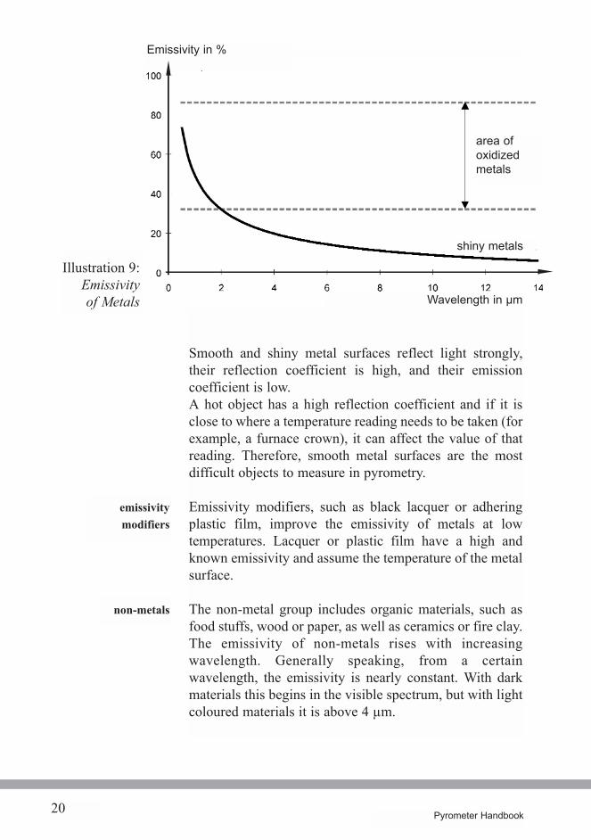
The emissivity of smooth metal surfaces is high at shortwavelengths and decreases with lengthening wavelengths.With oxidized and soiled metal surfaces results are notconsistent; emissivity may be strongly influenced bytemperature and/or wavelength.The emissivity of metals also changes with time due towear and tear, oxidation or soiling. Pieces of metal areoften smooth after processing and their surfaces arechanged by heat. Discolouration occurs and can befollowed by rust and scale. All this can change theemissivity and must be considered to avoid errors.However, so long as surfaces are not shiny, metals can bemeasured well in most cases.
emissivity setting
metals
6) see table 1, Emission coefficient for various materials
20 Pyrometer Handbook
Smooth and shiny metal surfaces reflect light strongly,their reflection coefficient is high, and their emissioncoefficient is low.A hot object has a high reflection coefficient and if it isclose to where a temperature reading needs to be taken (forexample, a furnace crown), it can affect the value of thatreading. Therefore, smooth metal surfaces are the mostdifficult objects to measure in pyrometry.
Emissivity modifiers, such as black lacquer or adheringplastic film, improve the emissivity of metals at lowtemperatures. Lacquer or plastic film have a high andknown emissivity and assume the temperature of the metalsurface.
The non-metal group includes organic materials, such asfood stuffs, wood or paper, as well as ceramics or fire clay.The emissivity of non-metals rises with increasingwavelength. Generally speaking, from a certainwavelength, the emissivity is nearly constant. With darkmaterials this begins in the visible spectrum, but with lightcoloured materials it is above 4 µm.
Illustration 9:Emissivityof Metals
emissivitymodifiers
non-metals
area ofoxidizedmetals
shiny metals
Wavelength in µm
Emissivity in %
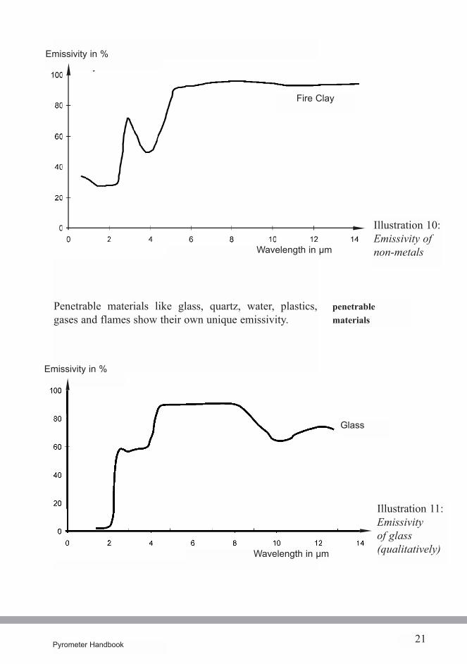
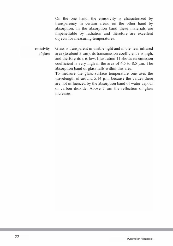
Penetrable materials like glass, quartz, water, plastics,gases and flames show their own unique emissivity.
21Pyrometer Handbook
Illustration 10:Emissivity ofnon-metals
Illustration 11:Emissivityof glass(qualitatively)
penetrablematerials
Emissivity in %
Wavelength in µm
Fire Clay
Glass
Wavelength in µm
Emissivity in %
22 Pyrometer Handbook
On the one hand, the emissivity is characterized bytransparency in certain areas, on the other hand byabsorption. In the absorption band these materials areimpenetrable by radiation and therefore are excellentobjects for measuring temperatures.
Glass is transparent in visible light and in the near infraredarea (to about 3 µm), its transmission coefficient t is high,and therfore its e is low. Illustration 11 shows its emissioncoefficient is very high in the area of 4.5 to 8.5 µm. Theabsorption band of glass falls within this area.To measure the glass surface temperature one uses thewavelength of around 5.14 µm, because the values thereare not influenced by the absorption band of water vapouror carbon dioxide. Above 7 µm the reflection of glassincreases.
emissivityof glass
23Pyrometer Handbook
5. Determining the Emissivity of an Object
Because the emissivity factor is so important in thecalculations that determine temperature, it is essential toestablish its value accurately for a given material.
There are several ways that this can be done. Tables maybe consulted to look up the values of the emissioncoefficient for many different materials (see Table 1). Formetals, however, the values are mostly qualitative.
The temperature of the object is first determined bymeasuring with a contact thermometer. Then the pyrometeris aimed at the object. Finally, the emissivity adjustmentknob is turned until both devices indicate the sametemperature. In order to use this method the object must besufficiently large and accessible.
Part of the object's surface is blackened with speciallacquer or soot whose emission coefficient is close to 1, isaccurately known and is stable up to the temperature to bemeasured. The pyrometer measures the temperature of theblackened surface, then it measures the untouched part ofthe surface. Then the emissivity adjustement knob is set sothat the temperature value of the previous measurement isshown.
The object is drilled to a depth of at least six times the drillhole's diameter. The diameter must be greater than the spotsize diameter of the pyrometer. Like a black body source,the drill hole is considered to have an emission coefficientof nearly 1. First, the temperature in the drill hole will bemeasured, then the pyrometer measures the surface, and bycorrect adjustment the temperature of the drill hole will bedetermined.
The emissivity of a sample object can be determined byspectrometer analysis. The manufacturer of yourpyrometer will arrange for this analysis to be carried out.
tables
partial blackening ofthe surface
drilling intothe object
comparisonwith contact-thermometers
analysis withspectrometer
24 Pyrometer Handbook
Rule:measure in the area of
short wavelengths
6. Choosing the spectral range
Choosing the correct spectral range is extremely importantfor accurate measurements using pyrometers.
6.1 Emissivity Errors
Here are some rules to observe to avoid emissivity errors.The most important rule is to choose a pyrometer thatmeasures in the shortest wavelength band.
This rule may be a disadvantage by not fully utilising theradiated energy, but it diminishes the influence of theemissivity.It is best to disregard this rule when strong daylight orartificial light influences the measurement, when theemissivity in the short wavelength band is poor (forexample, white lacquer) or when a certain area of thespectrum is needed for the measurement (for example,glass).
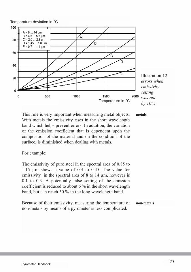
Illustration 12 shows the measuring errors of fivepyrometers which have different spectral bands. In thesecases the emissivity had been wrongly set by 10 %. If, forexample, one measures the temperature of an object heatedto 750 °C with a long wavelength pyrometer with aspectral band of 8 to 14 µm, a e setting mistake of 10 %results in an overall error of 60 °C. If, however, one uses apyrometer with a short wavelength spectral band of 0.7 to1.1 µm the measurement error is reduced to 7 °C assumingsimilar conditions.
Just by choosing the right band of the spectrum, errors canbe reduced nine fold.
25Pyrometer Handbook
This rule is very important when measuring metal objects.With metals the emissivity rises in the short wavelengthband which helps prevent errors. In addition, the variationof the emission coefficient that is dependent upon thecomposition of the material and on the condition of thesurface, is diminished when dealing with metals.
For example:
The emissivity of pure steel in the spectral area of 0.85 to1.15 µm shows a value of 0.4 to 0.45. The value foremissivity in the spectral area of 8 to 14 µm, however is0.1 to 0.3. A potentially false setting of the emissioncoefficient is reduced to about 6 % in the short wavelengthband, but can reach 50 % in the long wavelength band.
Because of their emissivity, measuring the temperature ofnon-metals by means of a pyrometer is less complicated.
Illustration 12:errors whenemissivitysettingwas outby 10%
metals
non-metals
Temperature in °C
Temperature deviation in °C
26 Pyrometer Handbook
7) see chapter 8.2, pyrometer models
In this case one must choose pyrometers which themanufacturer has designated for certain materials (forinstance, glass, plastics, ceramics, textiles, etc.). Thespectral areas in quality pyrometers are chosen so that theyare in the wavelengths which have a high and constantemissivity. At those wavelengths, the material isimpenetrable and absorption bands of water vapour andcarbon dioxide are not found here.In cases where the emission coefficient varies strongly,such as in metal-working processes, it is advisable to usepyrometers which can measure in more than one spectralrange. 2-colour pyrometers have proven especiallysuccessful 7).
27Pyrometer Handbook
6.2 Atmospheric Windows
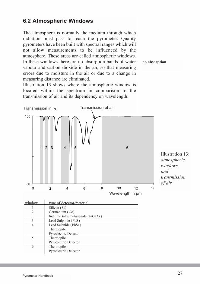
The atmosphere is normally the medium through whichradiation must pass to reach the pyrometer. Qualitypyrometers have been built with spectral ranges which willnot allow measurements to be influenced by theatmosphere. These areas are called atmospheric windows.In these windows there are no absorption bands of watervapour and carbon dioxide in the air, so that measuringerrors due to moisture in the air or due to a change inmeasuring distance are eliminated.Illustration 13 shows where the atmospheric window islocated within the spectrum in comparison to thetransmission of air and its dependency on wavelength.
no absorption
Wavelength in µm
Transmission in % Transmission of air
Illustration 13:atmosphericwindowsandtransmissionof air
window type of detector/material1 Silicon (Si)2 Germanium (Ge)
Indium-Gallium-Arsenide (InGaAs)3 Lead Sulphide (PbS)4 Lead Selenide (PbSe)
ThermopilePyroelectric Detector
5 ThermopilePyroelectric Detector
6 ThermopilePyroelectric Detector
28 Pyrometer Handbook
InGaAsGermanium
Lead Sulphide
Lead SelenideThermopilePyroelectric
ThermopilePyroelectric
In the spectral area "1" in illustration 13, temperatures ofover 550 °C can be measured. Pyrometers with silicondetectors measure the radiation in this window. Thisspectral area is usually used when measuring metals.
In window "2" temperatures of over 250 °C are measured.Here Germanium or Indium-Gallium-Arsenide detectors(InGaAs) are used together with optic filters. Metals aremostly measured in this window.
In window "3" temperatures of over 75 °C are measured.Here Lead Sulphide detectors (PbS) are used together withoptical filters. Metals with low temperatures are measuredin this spectral area.
In window "4" temperatures of over 50 °C are measured. Itis especially useful to measure objects behind flames orglass with a penetration depth of 20 mm. Pyrometers areused that have Lead Selenide (PbSe) detectors,Thermopiles, or Pyroelectric detectors, together with anoptical filter.
In window "5" temperatures of over 100 °C are measured.This works extremely well with glass surfaces with apenetration depth of 0.7 mm. Pyrometers are used here thathave Thermopiles and Pyroelectric detectors together withan optical filter.
In window "6" temperatures of over -50 °C are measured.Pyrometers are used that have Thermopiles andPyroelectric detectors together with an optical filter. It isused primarily to measure organic substances.
silicon
ThermopilePyroelectric
29Pyrometer Handbook
7. Spot Size and Measuring Distance
The optics of a pyrometer transmit the image of a sectionof the target area of the measured surface to the detector.This section is called the spot size8). By using differentlyshaped apertures in the pyrometer the spot size may beround or rectangular. The laws of optics mean that theimage enlarges as the distance from the lens increases.This is common knowledge in photography. It is possibleto measure small objects with pyrometers which aredesigned for use over short distances. The larger thedistance between pyrometer and object, the larger the spotsize diameter.
Pyrometers are available with two types of optics:
1) Fixed Optics2) Optics with variable focus
With fixed optics the minimum diameter of the spot sizerequires a fixed distance for measuring; the nominalmeasuring distance. A sharp image on the detector is theresult. A different optical variant, with different measuringdistances and spot sizes, enables the operator to use theinstrument correctly for various applications.
These optics allow the pyrometer to be focused on thetarget from various distances. This kind of equipment ispreferred for portable pyrometers. The diameter of the spotsize can be calculated by using the distance to target ratio,for example, 100:1. The resulting value expresses thedistance to diameter ratio. But there are also tables andspot size diagrams which can be used to determine the spotsize diameter.
fixed optics
optics withvariable focus
8) or spot size diameter
30 Pyrometer Handbook
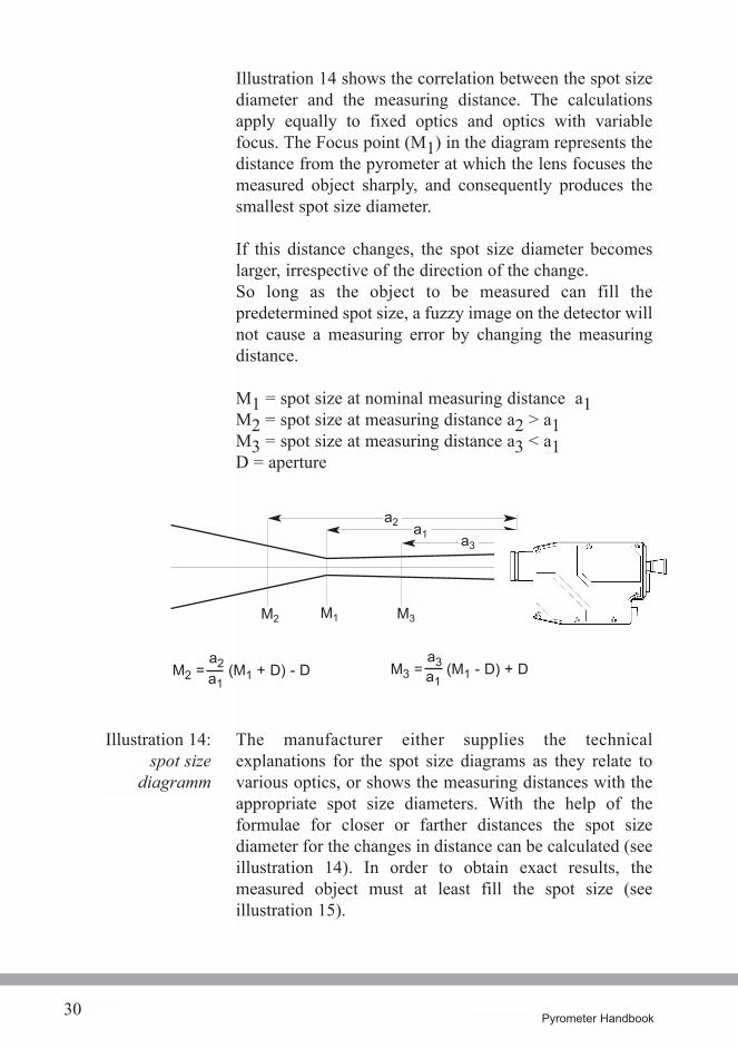
Illustration 14 shows the correlation between the spot sizediameter and the measuring distance. The calculationsapply equally to fixed optics and optics with variablefocus. The Focus point (M1) in the diagram represents thedistance from the pyrometer at which the lens focuses themeasured object sharply, and consequently produces thesmallest spot size diameter.
If this distance changes, the spot size diameter becomeslarger, irrespective of the direction of the change.So long as the object to be measured can fill thepredetermined spot size, a fuzzy image on the detector willnot cause a measuring error by changing the measuringdistance.
M1 = spot size at nominal measuring distance a1M2 = spot size at measuring distance a2 > a1M3 = spot size at measuring distance a3 < a1D = aperture
The manufacturer either supplies the technicalexplanations for the spot size diagrams as they relate tovarious optics, or shows the measuring distances with theappropriate spot size diameters. With the help of theformulae for closer or farther distances the spot sizediameter for the changes in distance can be calculated (seeillustration 14). In order to obtain exact results, themeasured object must at least fill the spot size (seeillustration 15).
Illustration 14:spot size
diagramm
a2 a1
M2 M1 M3
a3
D
M2 =a2a1
(M1 + D) - D M3 =a3a1
(M1 - D) + D
31Pyrometer Handbook
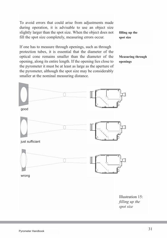
To avoid errors that could arise from adjustments madeduring operation, it is advisable to use an object sizeslightly larger than the spot size. When the object does notfill the spot size completely, measuring errors occur.
If one has to measure through openings, such as throughprotection tubes, it is essential that the diameter of theoptical cone remains smaller than the diameter of theopening, along its entire length. If the opening lies close tothe pyrometer it must be at least as large as the aperture ofthe pyrometer, although the spot size may be considerablysmaller at the nominal measuring distance.
filling up thespot size
Measuring throughopenings
Illustration 15:filling up thespot size
good
just sufficiant
wrong
Pyrometer Handbook32
Illustration 16:Construction
of aPyrometer
8. The Pyrometer
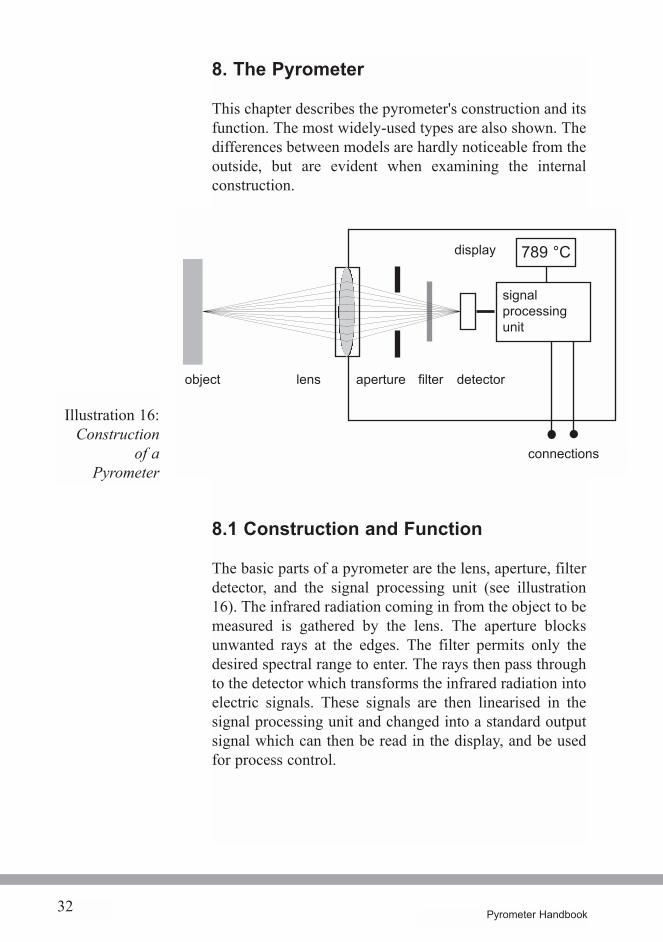
This chapter describes the pyrometer's construction and itsfunction. The most widely-used types are also shown. Thedifferences between models are hardly noticeable from theoutside, but are evident when examining the internalconstruction.
8.1 Construction and Function
The basic parts of a pyrometer are the lens, aperture, filterdetector, and the signal processing unit (see illustration16). The infrared radiation coming in from the object to bemeasured is gathered by the lens. The aperture blocksunwanted rays at the edges. The filter permits only thedesired spectral range to enter. The rays then pass throughto the detector which transforms the infrared radiation intoelectric signals. These signals are then linearised in thesignal processing unit and changed into a standard outputsignal which can then be read in the display, and be usedfor process control.
789 °C
object lens aperture filter detector
signalprocessingunit
display
connections
33Pyrometer Handbook
8.2 Pyrometer Types
The differences between spectral band pyrometers, totalband pyrometers, and 2-colour pyrometers are describedbelow.
In this category are narrow band pyrometers and broadband pyrometers.
These pyrometers measure the radiation from a narrowwavelength band, usually just around one wavelength. Byusing interference filters and appropriate detectors acertain wavelength or a certain wavelength band is chosen.They are frequently used when measuring glass at5.14 µm. Metals are also measured with them since theirrate of emissivity is high only in a narrow band 9).
These have a similar construction to that of the narrowband pyrometer. By using other filters and detectors theradiation from a wider wavelength band is measured (forexample, 8 to 14 µm). These pyrometers are used formeasuring organic materials because they have, in general,a high and constant emissivity at longer wavelengths.
These pyrometers are built to detect more than 90% of theemitted radiation of an object. This requires specialdetectors, lenses and filters which are sensitive to almostthe whole spectrum. Today, total band pyrometers arerarely used due to the major errors experienced(atmospheric window, emissivity).
9) see chapter 4, emissivity of various materials
broad bandpyrometers
total bandpyrometers
narrow bandpyrometers
spectral bandpyrometers
34 Pyrometer Handbook
2-colourpyrometer
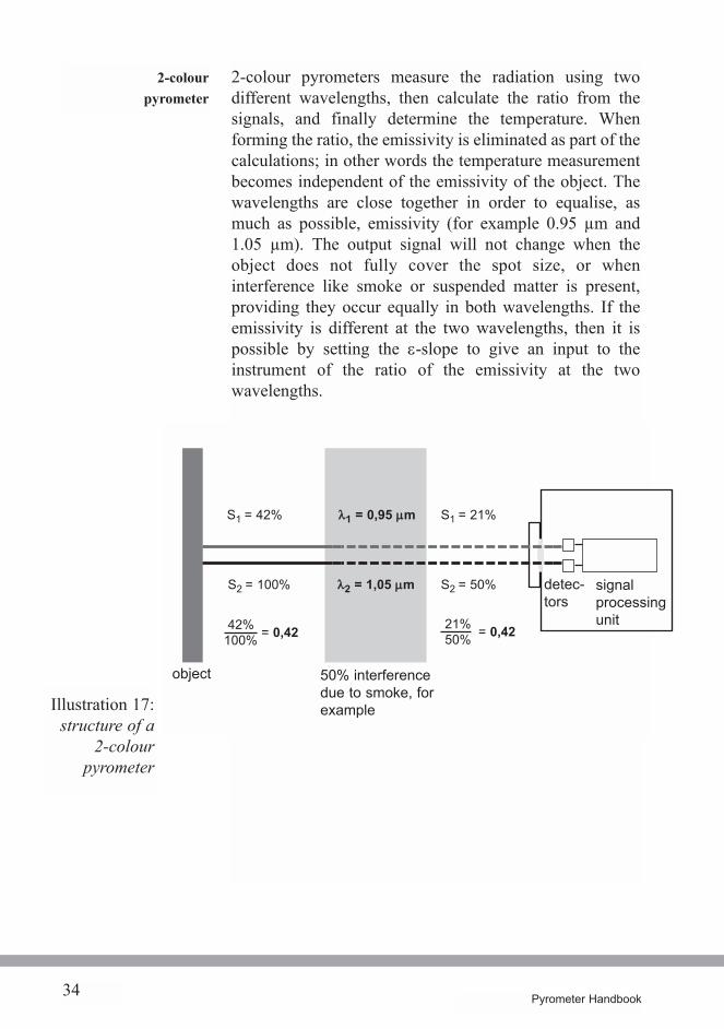
2-colour pyrometers measure the radiation using twodifferent wavelengths, then calculate the ratio from thesignals, and finally determine the temperature. Whenforming the ratio, the emissivity is eliminated as part of thecalculations; in other words the temperature measurementbecomes independent of the emissivity of the object. Thewavelengths are close together in order to equalise, asmuch as possible, emissivity (for example 0.95 µm and1.05 µm). The output signal will not change when theobject does not fully cover the spot size, or wheninterference like smoke or suspended matter is present,providing they occur equally in both wavelengths. If theemissivity is different at the two wavelengths, then it ispossible by setting the e-slope to give an input to theinstrument of the ratio of the emissivity at the twowavelengths.
Illustration 17:structure of a
2-colourpyrometer
signalprocessingunit
detec-tors
50% interferencedue to smoke, forexample
S1 = 42%
S2 = 100% l2 = 1,05 mm S2 = 50%
S1 = 21%
42%100% = 0,42 21%
50% = 0,42
object
l1 = 0,95 mm
35Pyrometer Handbook
2-colour pyrometers are used for difficult measuring tasks.
· high temperatures· blocked views or interference in the atmosphere (for
example, smoke, suspended matter)
· the object is smaller than the spot size (down to 10% ofthe spot size)
· changing, low, or unknown emissivity (for example,molten metal).
In order to measure both signals various constructions areused:
1. Sandwich detector2. Two separate detectors with different filters3. One detector with a rotating filter wheel
The disadvantage of a pyrometer with a rotating filterwheel is that the signals do not arrive simultaneously. Thecalculation of the ratio in the pyrometer increases thesensitivity toward changing signals in one of the twodetectors. If there are quickly changing temperatures ormoving objects a 2-colour pyrometer with rotating filtermay record an inaccurate temperature.
To measure temperatures of bright flames (the mostcommon type of flame) flame pyrometers have been foundto work well. The radiation coming to the pyrometer stemsfrom glowing soot or other burning particles. In this case,the soot factor “n” must be set on the pyrometer in order torecord the correct measurement.
flamepyrometers
bright flames
36 Pyrometer Handbook
4-colourpyrometer
non-luminousflames
For the measurement of temperatures of flames that arenon-luminous, such as gas burners, spectral pyrometerswhich measure the radiation of hot carbon dioxide in avery narrow spectral area, are required. That area liesbetween 4.5 and 4.65 µm.
4-colour pyrometers were developed for uses where theemissivity is very low and not stable during processing. 4-colour pyrometers measure the radiation intensitysimultaneously in four different spectral areas and they areable to adapt and make a correction of the emissivitysetting.These are very special pyrometers because the instrumentcollects data and effectively goes through a “learning”process which enables it to adapt to changing emissivities.Two temperature measurements are taken: a spectralradiation measurement and a contact measurement. Thecorresponding emissivity for each spectral band can thenbe calculated and stored.
37Pyrometer Handbook
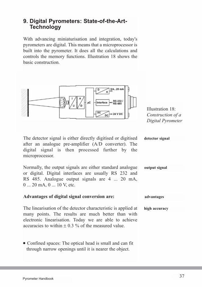
9. Digital Pyrometers: State-of-the-Art-Technology
With advancing miniaturisation and integration, today'spyrometers are digital. This means that a microprocessor isbuilt into the pyrometer. It does all the calculations andcontrols the memory functions. Illustration 18 shows thebasic construction.
The detector signal is either directly digitised or digitisedafter an analogue pre-amplifier (A/D converter). Thedigital signal is then processed further by themicroprocessor.
Normally, the output signals are either standard analogueor digital. Digital interfaces are usually RS 232 andRS 485. Analogue output signals are 4 ... 20 mA,0 ... 20 mA, 0 ... 10 V, etc.
Advantages of digital signal conversion are:
The linearisation of the detector characteristic is applied atmany points. The results are much better than withelectronic linearisation. Today we are able to achieveaccuracies to within ± 0.3 % of the measured value.
· Confined spaces: The optical head is small and can fitthrough narrow openings until it is nearer the object.
detector signal
output signal
advantages
high accuracy
Illustration 18:Construction of aDigital Pyrometer
38 Pyrometer Handbook
In the analogue system, mathematical functions requiredadditional equipment. However, with the digital system,these functions are now integrated into the pyrometerwhich eliminates the need for peripheral equipment. Anexample of these functions is the “maximum valuestorage”.
Communication with the pyrometer is also possible. A PCconnected with the appropriate software is usuallysufficient. All relevant data can be entered into thepyrometer, such as emissivity, response time, measuringrange, maximum value storage, etc.
Within the determined basic temperature measuring range,any sub-range can be set via the PC. Accuracy is notaffected by changing the measuring range.The advantagesare:
·When replacing old equipment the existing measuringrange can be entered. Other equipment and the cables canall be reused.
·Stores stock levels can be reduced as one range of digitalpyrometer can be programmed to cover several differentranges of analogue instruments.
·The new equipment is easier to use and reducescomplications.
· Optimum adaption to a specific application.
By using an appropriate black body source and software,digital pyrometers can be quickly recalibrated andchecked.
changing themeasuring range
setting of pyrometersvia the PC
old equipment
new digital equipment
optimum adaption
simplerecalibration
mathematicalfunctions
digitalcommunication
reducing stores stock
39Pyrometer Handbook
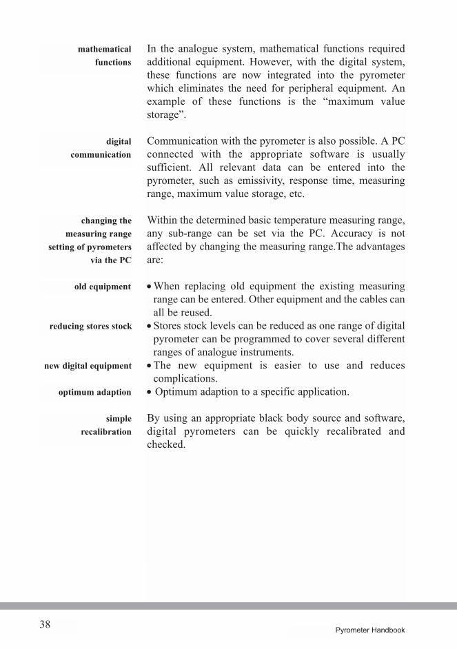
With the appropriate software all settings are simple to do.On-line graphics are standard today. The followingillustrations show how Windows software can communi-cate with pyrometers.
software
Illustration 19:main menu
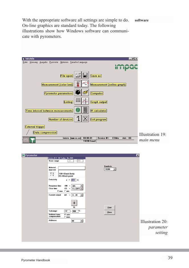
Illustration 20:parameter
setting
It is possible to input digital signals into separate software.The protocol to communicate with the pyrometer isgenerally very open, simple, and structurally clear. Atinterfaces such as RS 485, pyrometers are compatible withbus protocols. Manufacturers of quality pyrometers offergateway solutions for most bus controls. For the mostfrequently used bus protocols, integrated solutions areavailable.
40 Pyrometer Handbook
bus control
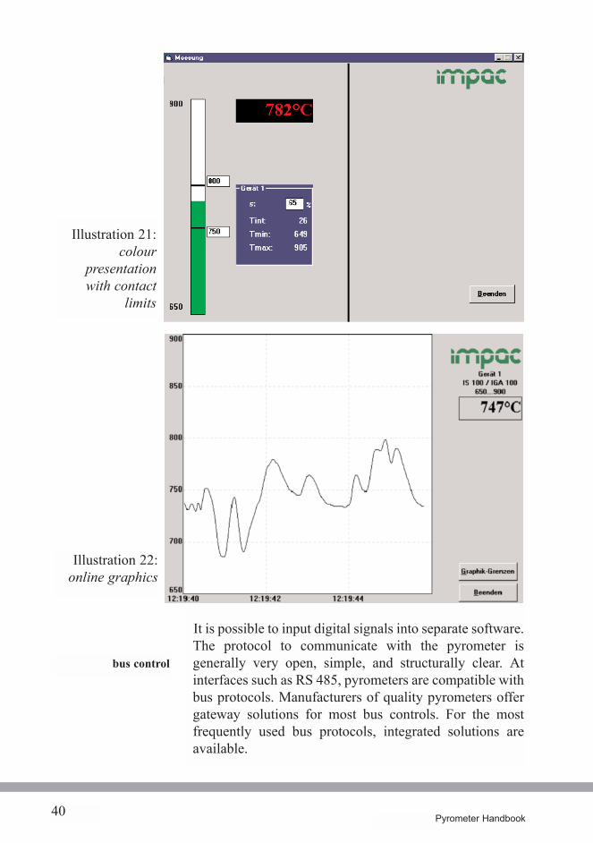
Illustration 21:colour
presentationwith contact
limits
Illustration 22:online graphics
41Pyrometer Handbook
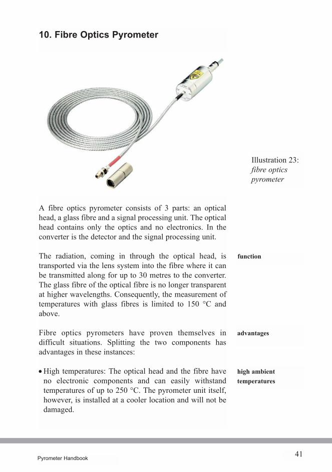
10. Fibre Optics Pyrometer
A fibre optics pyrometer consists of 3 parts: an opticalhead, a glass fibre and a signal processing unit. The opticalhead contains only the optics and no electronics. In theconverter is the detector and the signal processing unit.
The radiation, coming in through the optical head, istransported via the lens system into the fibre where it canbe transmitted along for up to 30 metres to the converter.The glass fibre of the optical fibre is no longer transparentat higher wavelengths. Consequently, the measurement oftemperatures with glass fibres is limited to 150 °C andabove.
Fibre optics pyrometers have proven themselves indifficult situations. Splitting the two components hasadvantages in these instances:
·High temperatures: The optical head and the fibre haveno electronic components and can easily withstandtemperatures of up to 250 °C. The pyrometer unit itself,however, is installed at a cooler location and will not bedamaged.
Illustration 23:fibre opticspyrometer
advantages
high ambienttemperatures
function
42 Pyrometer Handbook
strong electromagneticfields
measuring in avacuum
optical fibre
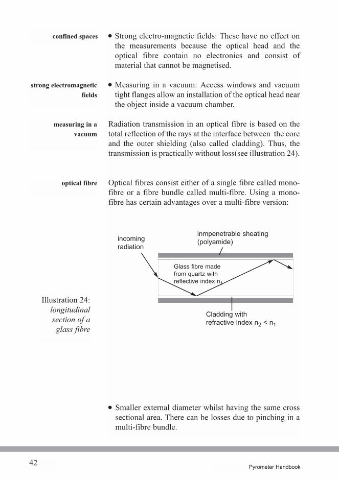
Illustration 24:longitudinalsection of aglass fibre
confined spaces · Strong electro-magnetic fields: These have no effect onthe measurements because the optical head and theoptical fibre contain no electronics and consist ofmaterial that cannot be magnetised.
· Measuring in a vacuum: Access windows and vacuumtight flanges allow an installation of the optical head nearthe object inside a vacuum chamber.
Radiation transmission in an optical fibre is based on thetotal reflection of the rays at the interface between the coreand the outer shielding (also called cladding). Thus, thetransmission is practically without loss(see illustration 24).
Optical fibres consist either of a single fibre called mono-fibre or a fibre bundle called multi-fibre. Using a mono-fibre has certain advantages over a multi-fibre version:
· Smaller external diameter whilst having the same crosssectional area. There can be losses due to pinching in amulti-fibre bundle.
Glass fibre madefrom quartz withreflective index n1
inmpenetrable sheating(polyamide)
Cladding withrefractive index n2 < n1
incomingradiation
43Pyrometer Handbook
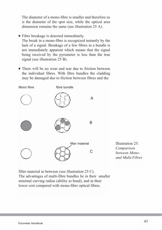
The diameter of a mono-fibre is smaller and therefore sois the diameter of the spot size, while the optical areadimension remains the same (see illustration 25 A).
· Fibre breakage is detected immediately.The break in a mono-fibre is recognized instantly by thelack of a signal. Breakage of a few fibres in a bundle isnot immediately apparent which means that the signalbeing received by the pyrometer is less than the truesignal (see illustration 25 B).
· There will be no wear and tear due to friction betweenthe individual fibres. With fibre bundles the claddingmay be damaged due to friction between fibres and the
filler material in between (see illustration 25 C).The advantages of multi-fibre bundles lie in their smallerminimal curving radius (ability to bend), and in theirlower cost compared with mono-fibre optical fibres.
Illustration 25:Comparisonbetween Mono-and Multi-Fibres
Mono fibre fibre bundle
filter material
A
B
C
44 Pyrometer Handbook
through thelens sighting
laser-pointer
pilot lights
11. Sighting and Viewing Devices
In order to adjust pyrometers the following sighting andviewing devices are available:
1. through the lens sighting system (TTL)2. integrated pilot light (halogen lamp, LED, laser)3. Temporary add-on targeting device
In general, one has to differentiate between devices that arebuilt-in and utilize the pyrometer's optics, and add-ondevices which are added externally and record incomingrays separately from the pyrometer optics. The built-indevices show the spot size accurately, and allow for theproper setting of the measuring distance.
· The user looks at the object as though he were lookingthrough a camera. In the centre of the viewing area aremarks which indicate the target area. To protect the eye,filters eliminate UV and infrared radiation, andbrightness at high temperatures can be reduced by usingpolarizing filters. Through the lens sighting systems arebuilt-in, but they may be purchased as add-onequipment.
· The pilot light is built into the pyrometer and indicatesby its point of light the size and the location of the targetarea. It is only usable if the measured object is not toobright. Generally, it is visible on an object up to atemperature of 1000 °C. Pilot lights can be a halogenlamp, LED, or laser.
· The laser pointer indicates with its ray the centre of thetarget area, or the target area itself. It is very useful whenmeasuring in darkness and for precision measurements.Because of the easily visible pointer light, small andmoving objects may be accurately targeted.
· This device is placed at the front of the pyrometer. It isavailable with a laser that lies in the lens axis, or withtwo lasers crossing at a defined distance from the lens.
add-on laserpilot light
45Pyrometer Handbook
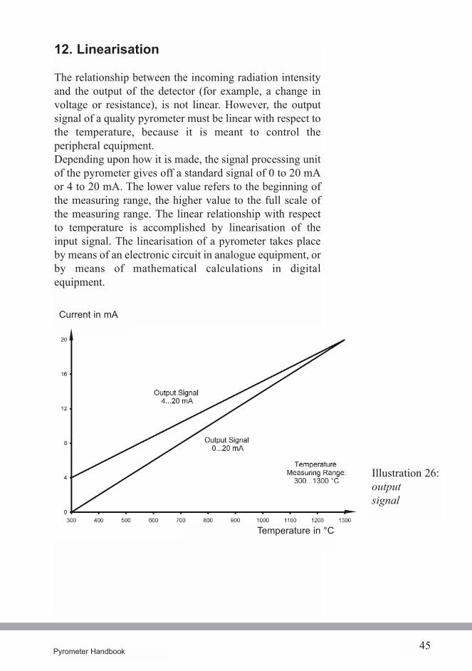
12. Linearisation
The relationship between the incoming radiation intensityand the output of the detector (for example, a change involtage or resistance), is not linear. However, the outputsignal of a quality pyrometer must be linear with respect tothe temperature, because it is meant to control theperipheral equipment.Depending upon how it is made, the signal processing unitof the pyrometer gives off a standard signal of 0 to 20 mAor 4 to 20 mA. The lower value refers to the beginning ofthe measuring range, the higher value to the full scale ofthe measuring range. The linear relationship with respectto temperature is accomplished by linearisation of theinput signal. The linearisation of a pyrometer takes placeby means of an electronic circuit in analogue equipment, orby means of mathematical calculations in digitalequipment.
Illustration 26:outputsignal
Current in mA
Temperature in °C
46 Pyrometer Handbook
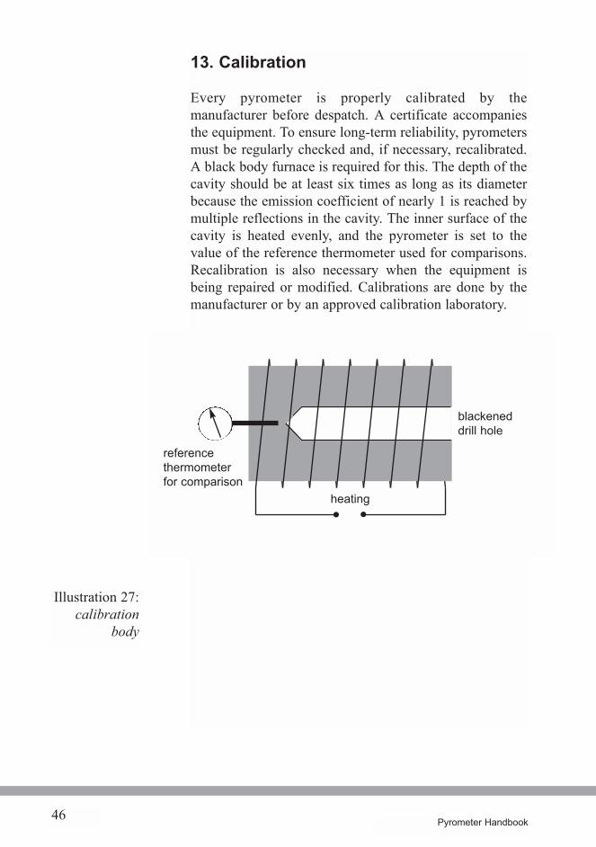
13. Calibration
Every pyrometer is properly calibrated by themanufacturer before despatch. A certificate accompaniesthe equipment. To ensure long-term reliability, pyrometersmust be regularly checked and, if necessary, recalibrated.A black body furnace is required for this. The depth of thecavity should be at least six times as long as its diameterbecause the emission coefficient of nearly 1 is reached bymultiple reflections in the cavity. The inner surface of thecavity is heated evenly, and the pyrometer is set to thevalue of the reference thermometer used for comparisons.Recalibration is also necessary when the equipment isbeing repaired or modified. Calibrations are done by themanufacturer or by an approved calibration laboratory.
Illustration 27:calibration
body
heating
referencethermometerfor comparison
blackeneddrill hole
47Pyrometer Handbook
14. Optics, Lenses and Window Material
One of the most important components of a pyrometer isthe optics. If lenses are used the material must be adaptedto the spectral properties of the detector. The material mustbe permeable to the pyrometer's spectral range, which isdetermined by the measuring range and the object to bemeasured.
· Crown glass (BK7) is used in pyrometers whichmeasure in the short wavelength band (up to 2.7 µm).Crown glass is very stable, resistant to chemicals andeasy to clean.
· Water-free quartz glass (Infrasil) is also used inpyrometers which measure in the short wavelength band(up to 3 µm).
· Calcium Fluoride (CaF2, Fluorspar) is used especiallywhen glass is measured. It can be used up to 10 µm andhas a high transmission coefficient.
· Germanium lenses are useful for pyrometers whichmeasure in the long wavelength band (up to 18 µm).They have a non-reflective surface and are non-transparent for visible light.
· Plastic lenses are used in simple pyrometers. They are,however, attacked by cleaning agents and scratch easily.They also do not tolerate high ambient temperatures.
The various colours of light have different focal lengths fornormal lenses. This divergence of colour is calleddispersion, and the resulting effect is called chromaticerror. To eliminate this error an achromat is used. This is acombination of a convex lens and a diverging lens eachwith a different refractive index. They are preciselydesigned so that in the observed wavelength range, thechromatic error is fully compensated for.
Crown glass
Quartz glass
Calcium fluoride
Germanium
Plastic
dispersionchromaticerrorachromat
48 Pyrometer Handbook
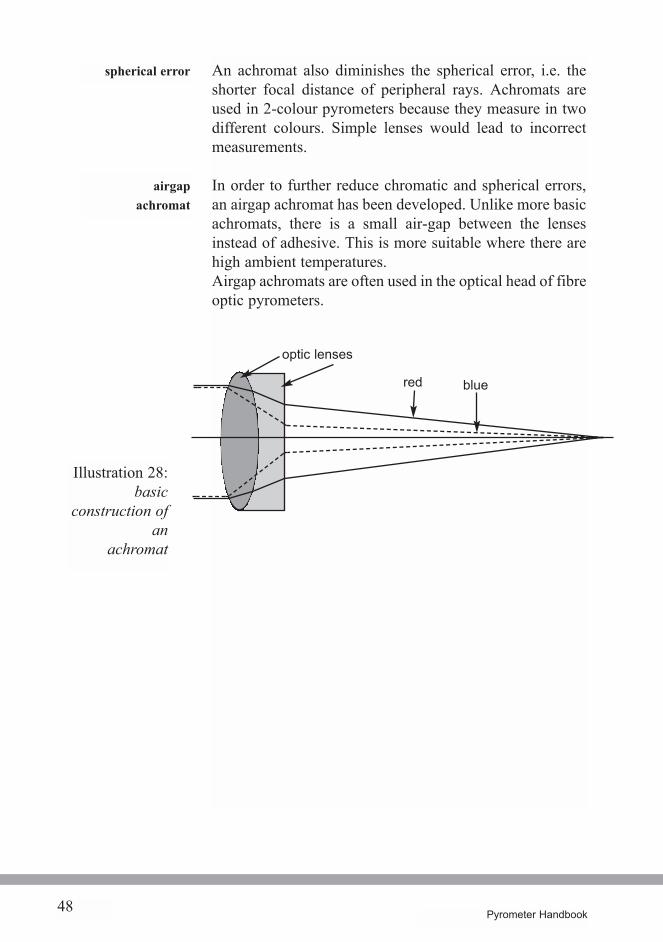
An achromat also diminishes the spherical error, i.e. theshorter focal distance of peripheral rays. Achromats areused in 2-colour pyrometers because they measure in twodifferent colours. Simple lenses would lead to incorrectmeasurements.
In order to further reduce chromatic and spherical errors,an airgap achromat has been developed. Unlike more basicachromats, there is a small air-gap between the lensesinstead of adhesive. This is more suitable where there arehigh ambient temperatures.Airgap achromats are often used in the optical head of fibreoptic pyrometers.
airgapachromat
spherical error
Illustration 28:basic
construction ofan
achromat
optic lenses
red blue
49Pyrometer Handbook
Window Materials
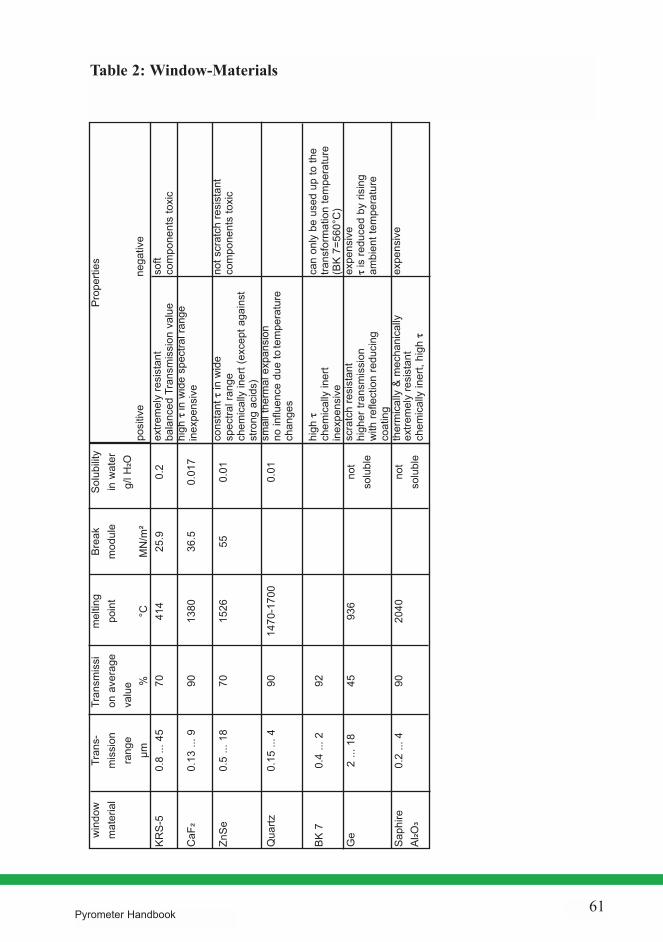
Pyrometers permit non-contact measurement oftemperatures of materials in furnaces, vacuum chambers orother enclosed areas. Of course, one needs a specialopening through which the pyrometer can "see" the surfaceof the object to be measured. In many cases these openingsmust be closed off by windows (for instance, in a vacuum,when under pressure, when dealing with gases, liquids orviscous masses). Depending on the temperature range andthe spectral range of the pyrometer, the correct choice ofwindow material is essential. Table 2 (see page 63) gives ageneral picture of the most commonly used materials andtheir technical data. The transmission range must bechosen so that it will not conflict with the pyrometer'sspectral range, which is determined by temperature and thematerial of the object to be measured.Among other necessary properties are mechanicalstrength, moisture & chemical resistance, and the ability towithstand thermal shocks.
The minimum thickness of the window (d min) to ensurestability under pressure is calculated with the formula:
r - radius of the windowS - safety factor (³ 4)c - method of window attachment(for instance c=1.1 for loose attachment)Dp - Differential pressureMr - Break modulus (material constant, see table 2)
Glass and quartz windows (used for high temperatures) arecost efficient, as are silicon and fluor- spar windows (tomeasure lower temperatures).
spectral range
mechanical stability
Mr
S . c . Dpdmin = r .
Pyrometer Handbook50
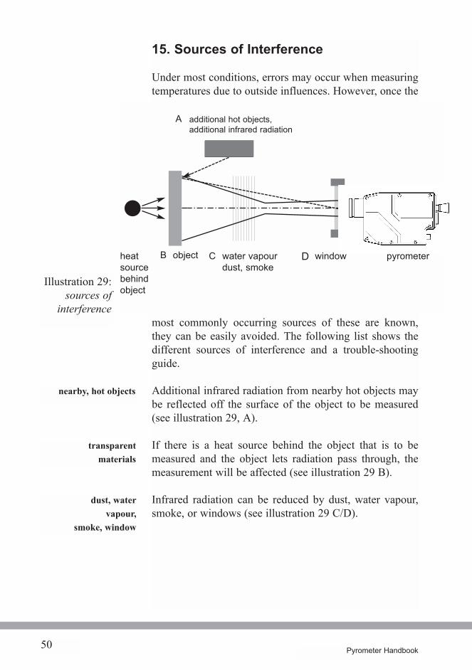
15. Sources of Interference
Under most conditions, errors may occur when measuringtemperatures due to outside influences. However, once the
most commonly occurring sources of these are known,they can be easily avoided. The following list shows thedifferent sources of interference and a trouble-shootingguide.
Additional infrared radiation from nearby hot objects maybe reflected off the surface of the object to be measured(see illustration 29, A).
If there is a heat source behind the object that is to bemeasured and the object lets radiation pass through, themeasurement will be affected (see illustration 29 B).
Infrared radiation can be reduced by dust, water vapour,smoke, or windows (see illustration 29 C/D).
nearby, hot objects
transparentmaterials
dust, watervapour,
smoke, window
Illustration 29:sources of
interference
B objectheatsourcebehindobject
windowwater vapourdust, smoke
additional hot objects,additional infrared radiation
pyrometer
A
DC
51Pyrometer Handbook
Trouble-Shooting
Additional infrared radiation such as daylight, indoor-lighting or an infrared source can be blocked with opticalfilters because of their predominantly short wavelengthcharacteristics. Quality pyrometers with silicon,germanium or InGaAs detectors are equipped withdaylight filters so that daylight or artificial light have noeffect on the measurement. Exceptions are pyrometerswith InGaAs detectors whose temperature range begins atunder 300 °C. In these cases a shade has to be used toprevent temperature errors.
The influence of radiation from infrared radiators orheaters, and certain kinds of furnaces (wavelengths up to4 µm), can be avoided by using pyrometers which work inthe long wavelength range (for example in the area of 8 to14 mm).
The radiation from a furnace wall or a hot enclosure havethe same wavelength range as the radiation coming fromthe object and cannot be filtered out. One must usemechanical devices to block out the unwanted radiation.Alternatively, the temperature can be mathematicallycorrected. So long as the temperature of these other hotobjects (i.e. the furnace wall) is constant, the input of acertain temperature value into the equation will suffice.However, if it changes, it must be measured with anadditional sensor. These values are then processed in thecalculating unit together with the signal from the object.When the measurement is done through a window, theemission coefficient must be adjusted to compensate forthe degree by which the radiation has been weakened 11).The influence of water vapour and carbon monoxide in theair can be eliminated by the correct choice of the spectralrange.
daylightartificiallight
infrared radiators
hot furnace wall
window
H2O, CO2
11) see page 51
52 Pyrometer Handbook
Influences that change at various times, such as dust,smoke and vapour, call for the use of a 2-colour pyrometer.
With transparent objects one must use a pyrometer whichis designed to work in a wavelength band for which theobject is impermeable. When the area behind the object tobe measured is cooler than the object itself, thetransparency of the object can be taken into account by acorrection of the emissivity.
When the spot size is not completely filled the location ofthe pyrometer must be changed 12). When this is notpossible different optics must be used.A 2-colour pyrometer will permit a measurement with aninsufficiently filled spot size so long as the background iscold.
dust, smoke
spot size not filled in
transparent objects
12) see illustration 15
53Pyrometer Handbook
16. Accessories
Industrial demands require the availability of specialaccessories. They have been developed to solve problemsand to ease difficulties in the application of measuringdevices.
An air purge unit protects the optics from dust and othersuspended particles, as well as from condensation. Itsconstruction in the shape of a round nozzle creates a cone-shaped air cushion in front of the lens. Thus, dust cannotsettle on the lens. When operating this air purge it isimportant to use dry and oil-free compressed air. In normalcircumstances a pressure of 0.2 bar is sufficient.
A radiation shield is used when most of the heat radiationcomes from the front.A cooling plate is a water-cooled plate. It removes theradiation from the front and does not heat up itself. Itallows the use of pyrometers in conditions of 10 to 20degrees above the normal maximum allowabletemperature for pyrometers.Cooling jackets are available as cooling coils or as fullyjacketed cooling systems. Coils allow for the operation ofpyrometers in high ambient temperatures. Fully jacketedcooling systems permit pyrometers to be used insurrounding temperatures of up to 100 °C with air cooling,and up to 250 °C with water cooling.
The pyrometer can be firmly set into position with anglebrackets. Adjustable positioning devices are used tofirmly fix pyrometers with variable alignment axes.
air purge unit
cooling accessories
mountingdevices
54 Pyrometer Handbook
Flange systems permit the attachment of pyrometers tofurnaces, containers or pipes.With a mounting tube, pyrometers may be built intocontainers (for example, asphalting or spray booths).A lamination slide is used as protection from incomingparticles when measurements are taken in an upwardangle. The slide is placed into a mounting tube.A ball and socket mounting is used to hold the pyrometerin place and allow quick adjustments of angle anddirection.
Ceramic tubes are available in open or closed form. Aclosed ceramic tube is used to measure the average innertemperature of a furnace or to measure the temperatureduring smelting (e.g. glass).An open ceramic tube is used to measure the surface of anobject inside a furnace.
With the help of scanning optics the spot size is movedback and forth across the object to be measured. A movingmirror oscillates around the centre position. With thescanner one can measure the temperature of movingobjects such as in the manufacture of wires. The scannershould always be used in connection with the maximumvalue storage unit. This unit stores the highest temperaturevalue of the object during the scanning process (with thisproviso; the surrounding temperature is lower than that ofthe object to be measured). Scanners may either be integralor be attached to the front of the optics. A pyrometer withscanner may also be used as a line scanner so long as theposition of the mirror is known.
ceramic tubes
scanningoptics
55Pyrometer Handbook
Indicators are designed to display the measuredtemperature. They can be integrated into the pyrometer butthey are also available as external equipment that willdisplay the temperature remotely from the pyrometer, suchas in a control room, or a switch box. Indicators can beeither analogue or digital, some with built-in maximumvalue storage functions and limit switches (to regulateheaters, etc.).
Recorders and printers provide graphic evidence of themeasured temperature.
Where there are swings in temperature, maximum valuestorage units allow the highest temperature value to berecorded and stored. Their fast response times ensure thateven the quickest changes in temperature are registered.These units have proven invaluable during metal heatingprocesses (for instance, during forging).When scale develops, temperature variations occur on thesurface being measured. With a maximum value storageunit the highest measured value is kept on record as itcorresponds to the temperature of the measured object. Byusing a double storage system one obtains a firm andsteady temperature indication. This system is used mostoften in combination with scanning optics and limitswitches.
When there are temperature swings the average valuecalculating unit determines the average value andsupplies a stable output signal which is then easily fed intoa controller.
Limit switches come into play when certain temperaturevalues are exceeded or are too low.
The converter changes the output signal of 2-wireequipment from 4 to 20 mA into 0 to 20 mA.
recorders andprinters
maximum valuestorage unit
average valuecalculating unit
limit switches
converter
indicators
56 Pyrometer Handbook
Calibrators check the accuracy of the pyrometers.
These converters change a RS 485 signal into a RS 232signal.
gateways allow for conversion of RS 485 signals toseveral bus systems.
digital converters
gateways
calibrators
57Pyrometer Handbook
Bibliography and Reading List
/1/ VDI/VDE - Richtlinien 3511, Blatt 4, TechnischeTemperaturmessungen, Strahlungsthermometrie,Jan. 1995
/2/ Walther; Gerber : InfrarotMesstechnik, VerlagTechnik, Berlin, 1981
/3/ DeWitt; Nutter : Theory & Practice of RadiationThermometry, John Wiley & Sons, Inc. / USA 1988
/4/ Herrmann: Wissensspeicher Infrarottechnik, Fachbuchverlag Leipzig 1990
/5/ Engel : Temperaturmessung mit Strahlungspyrometern, Reihe Automatisierungstechnik, Nr. 157, Ver-lag Technik, Berlin 1974
/6/ Lieneweg: Handbuch Technische Temperaturmessung, Vieweg & Sohn Verlagsgesellschaft mbH,Braunschweig 1976
/7/ Euler-Ludwig: Arbeitsmethoden der optischen Py-rometrie, Verlag Braun, Karlsruhe 1960
/8/ Weichert : Temperaturmessung in der Technik,Band 9, Kontakt u. Studium, expert-Verlag, Sindelfingen 1987
58 Pyrometer Handbook
/9/ Gerthsen, Kneser, Vogel: Physik, Springer-Verlag,Berlin Heidelberg New York 1982
/10/ Herder Lexikon Physik, Verlag Herder, Freiburg imBreisgau 1972
/11/ Levigion: Diskussion der Emissionsgradabhängigkeit von Gesamt-, Teilstrahl- und Quotienten-Pyro-metern, Archiv für technisches Messen,Heft 7/1974, Verlag R. Oldenbourg GmbH, Mün-chen
/12/ Lotzer : Temperaturen berührungslos messen, Elek-trotechnik 59, H 22, 25. November 1974

59Pyrometer Handbook
Tables
Pyrometer Handbook60
Table 1: Emissivity of various material
Mat
eria
l
stee
l, sh
iny
stee
l, ro
lled
stee
l, an
eale
dst
eel,
oxid
ised
copp
er, s
hiny
copp
er, o
xidi
sed
alum
iniu
m, s
hiny
alum
iniu
m, a
nodi
sed
NiC
r, sh
iny
NiC
r, an
odis
edco
al, g
raph
itesto
ne, g
roun
d, c
eram
icva
rnis
h, p
aint
woo
d, p
last
ics, p
aper
text
ileth
in g
lass
wat
er, s
now,
ice
spec
tral r
ange
0.7
... 1
.15
µm
0.40
... 0
.45
0.45
... 0
.55
0.70
... 0
.80
0.80
... 0
.90
0.06
... 0
.20
0.50
... 0
.80
0.05
... 0
.25
0.20
... 0
.40
0.20
... 0
.40
0.65
... 0
.90
0.70
... 0
.95
0.40
... 0
.70
--- --- ---0.
05 ..
. 0.1
0---
spec
tral r
ange
1.4
... 1
.8 µ
m
0.30
... 0
.40
0.35
... 0
.50
0.70
... 0
.85
0.80
... 0
.90
0.06
... 0
.20
0.40
... 0
.80
0.05
... 0
.25
0.10
... 0
.40
0.20
... 0
.40
0.65
... 0
.80
0.70
... 0
.95
0.40
... 0
.70
--- ---0.
70 ..
. 0.8
50.
05 ..
. 0.2
0---
spec
tral r
ange
2 ...
2.5
µm
0.20
... 0
.35
0.25
... 0
.40
0.45
... 0
.70
0.75
... 0
.85
0.06
... 0
.10
0.40
... 0
.80
0.04
... 0
.20
0.10
... 0
.40
0.20
... 0
.40
0.65
... 0
.80
0.70
... 0
.95
0.40
... 0
.70
--- ---0.
60 ..
. 0.8
50.
60 ..
. 0.8
5---
spec
tral r
ange
4.9
... 5
.5 µ
m
0.10
... 0
.30
0.20
... 0
.30
0.30
... 0
.60
0.70
... 0
.90
0.05
... 0
.10
0.20
... 0
.70
0.03
... 0
.15
0.10
... 0
.40
0.20
... 0
.40
0.65
... 0
.80
0.70
... 0
.95
0.50
... 0
.80
0.60
... 0
.90
0.60
... 0
.90
0.70
... 0
.90
0.70
... 0
.90
---
spec
tral r
ange
8 ...
14
µm
0.10
... 0
.30
0.20
... 0
.30
0.30
... 0
.60
0.60
... 0
.80
0.03
... 0
.10
0.20
... 0
.70
0.02
... 0
.15
0.95
0.10
... 0
.30
0.50
... 0
.80
0.70
... 0
.95
0.60
... 0
.95
0.70
... 0
.95
0.80
... 0
.95
0.75
... 0
.95
0.75
... 0
.95
0.90
... 0
.95
Prop
ertie
s
posi
tive
nega
tive
extre
mel
y re
sist
ant
bala
nced
Tra
nsm
issi
on v
alue
high
t in wide spectra
l range
inex
pens
ive
cons
tant
t in
wid
esp
ectra
l ran
gech
emic
ally
iner
t (ex
cept
aga
inst
stro
ng a
cids
)sm
all t
herm
al e
xpan
sion
no in
fluen
ce d
ue to
tem
pera
ture
chan
ges
high
tch
emic
ally
iner
tin
expe
nsiv
esc
ratc
h re
sist
ant
high
er tr
ansm
issi
onw
ith re
flect
ion
redu
cing
coat
ing
ther
mic
ally
& m
echa
nica
llyex
trem
ely
resi
stan
tch
emic
ally
iner
t, hi
ght
soft
com
pone
nts
toxi
c
not s
crat
ch re
sist
ant
com
pone
nts
toxi
c
can
only
be
used
up
to th
etra
nsfo
rmat
ion
tem
pera
ture
(BK
7=56
0°C
)ex
pens
ive
t is
redu
ced
by ri
sing
ambi
ent t
empe
ratu
re
expe
nsiv
e
Pyrometer Handbook 61
win
dow
mat
eria
l
KRS-
5
CaF
²
ZnSe
Qua
rtz
BK 7
Ge
Saph
ireAl
²O³
Tran
s-m
issi
onra
nge
µm0.
8 ...
45
0.13
... 9
0.5
... 1
8
0.15
... 4
0.4
... 2
2 ...
18
0.2
... 4
Tran
smis
sion
ave
rage
valu
e % 70 90 70 90 92 45 90
mel
ting
poin
t
°C 414
1380
1526
1470
-170
0
936
2040
Brea
km
odul
e
MN
/m²
25.9
36.5
55
Solu
bilit
yin
wat
erg/
l H²O
0.2
0.01
7
0.01
0.01 no
tso
lubl
e
not
solu
ble
Table 2: Window-Materials
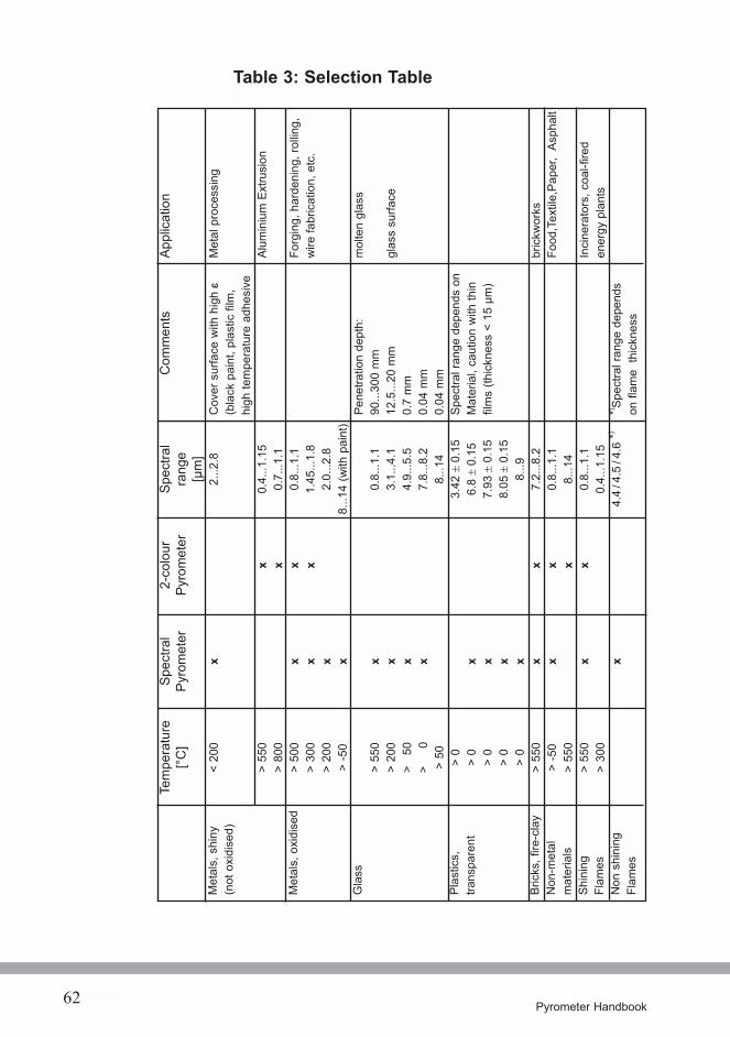
Table 3: Selection Table
62 Pyrometer Handbook
Met
als,
shi
ny(n
ot o
xidi
sed)
Met
als,
oxi
dise
d
Gla
ss
Plas
tics,
trans
pare
nt
Bric
ks, f
ire-c
lay
Non
-met
alm
ater
ials
Shin
ing
Flam
esN
on s
hini
ngFl
ames
Tem
pera
ture
[°C]
< 20
0
> 55
0>
800
> 50
0>
300
> 20
0>
-50
> 55
0>
200
> 50
> 0
> 50 > 0
> 0
> 0
> 0
> 0
> 55
0>
-50
> 55
0>
550
> 30
0
Spec
tral
Pyro
met
er
x x x x x x x x x x x x x x x x x
2-co
lour
Pyro
met
er
x x x x x x x x
Spec
tral
rang
e[µ
m]
2...2
.8
0.4.
..1.1
50.
7...1
.10.
8...1
.11.
45...
1.8
2.0.
..2.8
8...1
4 (w
ith p
aint
)
0.8.
..1.1
3.1.
..4.1
4.9.
..5.5
7.8.
..8.2
8...1
43.
42± 0.15
6.8
± 0.15
7.93
± 0.15
8.05
± 0.15
8...9
7.2.
..8.2
0.8.
..1.1
8...1
40.
8...1
.10.
4...1
.15
4.4
/ 4.5
/ 4.6
*)
Com
men
ts
Cov
er s
urfa
ce w
ith h
igh
e(b
lack
pai
nt, p
last
ic fi
lm,
high
tem
pera
ture
adh
esiv
e
Pene
tratio
n de
pth:
90...
300
mm
12.5
...20
mm
0.7
mm
0.04
mm
0.04
mm
Spec
tral r
ange
dep
ends
on
Mat
eria
l, ca
utio
n w
ith th
infil
ms
(thic
knes
s <
15 µ
m)
*) Spec
tral r
ange
dep
ends
on fl
ame
thic
knes
s
Appl
icat
ion
Met
al p
roce
ssin
g
Alum
iniu
m E
xtru
sion
Forg
ing,
har
deni
ng, r
ollin
g,w
ire fa
bric
atio
n, e
tc.
mol
ten
glas
s
glas
s su
rface
bric
kwor
ksFo
od,T
extil
e,Pa
per,
Asph
alt
Inci
nera
tors
, coa
l-fire
den
ergy
pla
nts
Pyrometer Handbook 63
Terminology
-273.15 °C. lowest possible temperature at whichmolecules are not active.
Transfer of energy to a material by means of waveradiation or particle radiation. Assimilation of energy(light, heat), gases or liquids, through substances.
Spectral areas where materials absorb radiation and wherethey are not permeable for heat radiation.
Relationship of absorbed radiation to all incomingradiation.
Lens combination of weak refracting crown glass andstrong refracting flint glass to alleviate chromatic errors.
Special form of achromat that reduces chromatic errors aswell as spherical errors.
Opening of the shutter of an objective.
Spectral areas where air is permeable to heat radiation.
Accessory to accurately adjust the direction of the spotsize of the pyrometer.
Accessory to keep dust off the optics.
Forms the average value of the signal for a specified lengthof time.
A body that absorbs all incoming radiation in allwavelengths which has an emissivity value of 1, or a bodywhich emits the maximum possible radiation (at allwavelengths) for its temperature.
Needed for calibrating and proving purposes, its openingradiates almost like a black body.
absolute zero
absorption
absorption, bands of
absorption coefficient
achromat
achromat, air-gap
aperture
atmospheric windows
aiming device
air purge unit
average valuecalculator
black body
black body furnace
64 Pyrometer Handbook
To measure accurately in comparison with internationaltemperature standards.
Equivalent to a black body source and is used as acalibration device.
Somewhat sour tasting, colourless, non flammable gas(CO2).
A certificate that verifies the accuracy of an instrument(This can be in a format that is traceable to NationalStandards).
A change in the temperature of the equipment due to achange in the ambient temperature, is compensated forautomatically.
Accessory to allow the use of pyrometers at high ambienttemperatures.
Temperature measuring device which measures an object´stemperature by being in contact with it, for examplethermocouples, or resistance thermometers (e.g.Pt100).
Colour error. Single lenses have differing focal distancesfor different wavelengths.
Equipment to store measured values, allows for lateranalysis of these values.
Receptor for radiation. Changes heat radiation into anelectrical signal.
Refraction of light into various colours.
Ratio of the radiation emitted by a surface to that emittedby a black body at the same temperature.
A device on the pyrometer that adjusts the instrument tothe emissivity (emission coefficient) of the measuredobject.
calibration
calibration body
carbon dioxide
certificate ofconformity/ calibration
compensation forsurrounding
temperatures
cooling device
contact thermometer
chromatic error
data storage unit
detector
dispersion
emissivity(emission coefficient)
emissivity setting
65Pyrometer Handbook
Pyrometer whose optic head is connected to a convertervia a light conductor.
Optical pyrometer with which the user compares thebrightness of the measured object with a built-in filament.
Optics with fixed focal distance with no adjustments.
A material that allows only a limited spectral range to passthrough it.
Pyrometers used to measure hot flames.
Pyrometer which is sensitive to heat radiation in the entirespectral range.
Body whose emissivity e < 1 is considered constant at allwavelengths.
A measure of the ability of a material to retain heat.
A measureof the ability of a material to conduct heat.
Equivalent to a black body source, used to calibratepyrometers.
The effect of radiation.
RS 232 or RS 485 are required to communicate betweendigital pyrometers and other digital equipment.
Accessory to facilitate exact adjustment of pyrometer. Sothat it points accurately at the object to be measured
A current relay trip that operates with either increasing ordecreasing temperature. i.e. high/low alarm (located in thepower supply or digital display).
Part of signal processing in a pyrometer. Establishes theproportion between measured temperature and outputsignal.
fibre opticspyrometer
filament pyrometer
fixed optic
filter
flame pyrometers
full radiationpyrometer
grey body
heat capacity
heat conductivity
hollow body
intensity
interface
laser pointer
limit switches
linearisation
66 Pyrometer Handbook
Accessory to store the highest temperature value in a settime interval.
Highest point of the measuring range (highest measurabletemperature by pyrometer).
Distance between object and forward most edge of thelens.
Maximum deviation between radiated heat and truetemperature.
Lowest point of the measuring range (lowest measurabletemperature by pyrometer).
Optic system which consists of several lenses and mirrorsand which projects the object's image to the detector of thepyrometer.
Objective of a pyrometer that is connected by optical fibreto the converter unit, it may be placed near the object inphysically difficult to reach situations and it withstandshigh ambient temperatures.
Glass fibre for conducting light. Uses total reflection in thefibre.
Aiming device for the spot size (halogen lamp, LED, orlaser).
describes the intensity in the wave lengthinterval dl (between l and l*dl).
C1 = 3,74 · 10-16 Wm2 C2 = 1,44 · 10-2 mKC1; C2: radiation constant
maximum valuestorage unit
maximum temperaturerange
measuring distance
measuring uncertainty
minimum temperaturerange
objective
optical head
optical fibre
pilot light
Planck´s law
dM = C1 1 1
l5 e C2/lT -1dl
67Pyrometer Handbook
An instrument to measure temperatures without makingcontact with the object to be measured(radiation thermometer).
Pyrometer which measures in several spectral ranges andcalculates mathematically the true temperature of theobject by combining the different signals coming in. (Forexample, a 2-colour pyrometer).
Pyrometer which uses only a portion of the radiationcoming from the object to measure the temperature.Depending upon the range of the spectrum used, onedistinguishes between spectral pyrometers and bandradiation pyrometers.
Pyrometer which simultaneously measures in fourdifferent spectral ranges and then calculates the truetemperature mathematically from the received signals.
Pyrometer which measures in two neighbouring spectralranges and calculates the temperature from the ratio of theoutput signals.
Relationship of intensity of reflected to incomingradiation.
Return of radiation rays at the border between twomaterials (may be focused or diffuse).
The uncertainty with which a measured value may bereproduced under equal conditions.
Oxidised layer which is created on the surface of steelduring the heating process. This layer has a lowertemperature than the steel itself.
Equipment to re-direct the pyrometer radiation setting to aline vertical to the optic axis, so that the surface of theobject can be scanned. The scanner moves the spot sizeacross the object.
pyrometer
multiple colourpyrometer
pyrometer,partial radiation-
pyrometer, 4-colour
pyrometer, 2-colour
rate of reflection
reflection
repeatability
scale
scanning optics
68 Pyrometer Handbook
An adjustable device to alter the amount of light enteringthe lens system.
All the wavelengths produced by electro-magneticradiation.
The area of the spectrum which is used by the pyrometerwhen taking readings.
Measuring device which determines the radiation intensityin relation to the wave length.
Boltzman constant, T: absolute temperature describes thetemperature dependency of the radiated intensity of thetotal wavelength range.
M = s · T4 s = 5,67 · 10-8
Shows the spot size as it relates to the measuring distance.
Area on the object from which the pyrometer, receivesmost (90 %) of the signals.
Black carbon in powder form, residue of incompleteburning of organic substances (very high emissivity).
The heat capacity of a material (solid, liquid or gas),measured in absolute Kelvin, °Celsius, °Fahrenheit, orReaumur.Umrechnung: K = °C + 273,15°
°C = 0,555 (°F - 32) = 1,25 °R°F = 1,8 °C + 32 = 2,25 °R + 32°R = 0,8 °C = 0,444 (°F - 32)
Accessory for accurate adjustments. Uses a laser lightsource.
shutter
spectrum
spectral range
spectrometer
Stefan-Boltzmann-law
spot size diagram
spot size
soot
temperature
through lens sightingsystem
Wm-2 · K- 4
69Pyrometer Handbook
Official calibration by an authorised calibration laboratory.
A temperature sensor that consists of two wires connectedtogether made from different metals (e.g. Ni-NiCr) ormetal alloys, which produces an electrical voltage that isdependant on temperature.
Complete light reflection at the interface between a denseoptic medium and a thin optic medium.
The passing of radiation through a solid, liquid or gas.
Ratio between intensity of radiation that has passedthrough, to the incoming radiation.
Optics with adjustments so that a sharp image can beobtained.
Transparent disc which closes the opening through whichthe pyrometer measures.
Describes the length of a wave between two points in asingle phase.
Describes the relation between the wavelengthand the temperature whereby this wavelengthshows the maximum radiation intensity.
traceable certificate
thermocouple
total reflection
transmission
transmissioncoefficient
variable optics
viewing window
wavelength
Wien´s law
lmax =C3T
C3 = 2,898 · 10-3 mK

70 Pyrometer Handbook
71Pyrometer Handbook
Index
r 17
t 17
e 17
a 17
g-radiation 13
0 to 10V 37
0/4 to 20mA 37
A/D-converter 38
absolute zero 7, 65
absorption 16, 65
absorption coefficient 22, 65
achromat 49, 65
adaptive emissivity correction 37
aggressive materials 11
air gap achromat 50, 68
air purge unit..65
Al2O3 63
aluminium 62
aluminium, plain 62
aluminium presses 64
analogue standardised signals 38
aperture 31,65
artificial light 25
atmospheric window 27, 65
attached view finder 45
attachment points 10
average value calculator 57, 68
bands of absorption 22, 65
basic measuring range 39
bend, ability to 44
BK-7 63
black body 12, 69
black body furnace 70
black body radiation source 39
black body source 39
Boltzmann, Ludwig 12
brick manufacture 64
brickworks 64
bright flames 36
burning particles 36
bus protocol 41
bus system 41
CaF2 49, 63
Calcium Fluoride 49
calculating and storing functions 38
calibrating 48, 67
calibration check 39
carbon 62
Carbon Dioxide 22, 27, 37, 67
ceramic tube 56
ceramics 20, 62
certificate of calibration 48, 69
chromatic error 49, 65
cladding 43
clear line of view 11
CO2 53
Coal 62
communication protocol 41
compensating for
surrounding tempratures 71
condensation 55
conducting heat 9
contact thermometer 65
converter 57
cooling, device 55, 67
cooling, housing 55
cooling, plate 55
copper, oxidized 62
copper, plain 62
correction of emissivity 37
correlation between
temperature /radiation 25
crown glass 49
data storage unit 66
daylight 25, 53
daylight filter 53
detector, material 28
difficult access 9
diffuse reflection 16
digital converter 58
digital evaluation of signals 38
digital intersecting points 38
digital pyrometer 38
digital standardised signals 38
discolourations 19
dispersion 49, 66
distance correlation 30
double storage system 57
double storage unit 57
drillings 10
dual line equipment 57
earth 62
electricity conducting object 11
electro-magnetic field 43
electro-magnetic spectrum 7
emissivity 17, 66
emissivity adjuster 20
emissivity determination 23
emissivity error 25
emissivity setting 19, 66
emissivity correction 37
energy 7
error causes 52
fibre breakage 44
fibre bundle 43
filament pyrometers 8
filling of spot size 32
filter 66
fire clay 20
fireproof brick 64
flame pyrometer 36, 66
flame thickness 64
flames 21, 29
flames, bright 36, 64
flames, non luminous 37, 64
flange system 56
Fluorspar 49
focal distance 49
food processing 8
food stuffs 20, 64
four-colour pyrometer 37, 71
friction temperature 10
full cooling housing 55
full range radiation pyrometer 34, 66
furnace 64
furnace cover 20
furnace wall 53
fuzzy image 31
gas burner 37
gateway solution 37
Ge 63
germanium detector 29
germanium lenses 49
glass 21, 22, 64
glass fibre 42
glass manufacture 8
glass melting 64
glass surface 64
glass surface temperature 22
glowing 14
glowing soot particles 36
graphite 62
grey body 18, 67
guidance of the process 8
H2O 53
halogen lamp 45
hardening 64
72 Pyrometer Handbook
heat capacity 11, 71
heat conductivity 71
heating 57
Herschel, Friedrich Wilhelm 12
high accuracy 38
hollow body 67
hot add-ons 52
hot gases 21
ice 62
ideal body 12
impediments to viewing 36
Indium-Gallium-Arsenide detector 29
infrared 67
infrared radiation 7
Infrasil 49
inspection of chimney pilot light 11
integration 38
intensity 67
intensity curve 13
intersection 39 69
intervening filters 34
Kern-Mantel plane 43
KRS-5 63
lacquer 62
lamination insert 56
laser 45
laser pilot light attachment 45, 46
laser pointer 45, 67
Lead Sulphide detector 29
Lead Selenium detector 29
LED 45
lenses 49
light conducting pyrometer 42, 67
light conductor 42, 67
line scanner 56
linearisation 33, 38, 47, 67
loss due to pinching 44
material susceptible
to magnetization 42
material properties 16
maximum of spectral intensity 14
maximum value storage unit 38, 57, 68
measuring distance 30, 68
measuring error 25
measuring head 42
measuring range beginning 47, 68
measuring range end 47, 68
measuring tip 9
measuring uncertainty 66
melting 36
metal processing 8
metal surface, plain 19
metals 19
metals, oxidized 64
metal, plain 64
micro processor 38
minimal delays 9
minimal thickness 51
miniaturization 38
mirror 16
moisture 27
mounting equipment, adjustable 55
moving objects 9
multi-fibre 43
multiple colour pyrometer 68
multiple reflections 48
negative influences 35, 52
Newton, Isaac 12
Ni-CrNi thermo elements 10
NiCr, oxidized 62
NiCr, plain 62
nominal measuring distance 30
non adjustable optics 30, 66
73Pyrometer Handbook
non-metals 19, 64
non-luminous flames 37
objective 30, 68
on-line graphics 40
openings 32
optic filter 29
optic head 68
optics 30
organic substances 20
out of adjustment 32
output signal 35
oxidation 19
paper 20, 62, 64
parameters for the process 8
partial measuring range 39
PC 39
penetration depth 29, 64
peripheral accessories
peripheral rays 33
pilot light 45, 69
Planck´s radiation law 69
Planck, Max 12
plastic(synthetic)9 62
plastic film 11
plastic lenses 49
plastics, transparent 64
polarization filter 45
poor heat conductivity 11
principle of wireless radio 7
printer 57
prism 12
processing signals 38
pyroelectric detector 29
pyrometer 69
quartz 21, 63
quartz glass 43, 49
radiation band pyrometer 34
radiation flow 17
radiation source 57
radiation theory 12
radiation thermometer 8
radiation tin 55
radiation transfer 42, 43
radiation-permeable materials 19
real body 18
recorder 57
recording 33
recording instruments 56
reduced space condition 43
reflection..16, 69
reflection coefficient 69
refraction index 43
refuse incineration 64
relative distribution of intensity 13
reproducability 69
response time 39
Roentgen radiation 13
rolling iron 64
rotating filter wheel 36
round nozzle attachment 55
RS 232 38
RS 485 38
rust 19
sandwich factor 36
scale 19, 72
scale development 57
scratches 10
selective absorption 16
setting time 9
shutter 30, 65
silicon detector 2
signal processing unit 33
smelter 11, 64
smoke 35
snow 62
software 39
74 Pyrometer Handbook
soiling 19, 55soot factor 36
soot 17, 69
spectral area 15,70
spectral colours 12
spectral intensity 13
spectral pyrometer 34
spectrometer 24, 70
spectrum..70
spherical error 50
spot size 30, 68
spot size diagram 30, 31
spot size diameter 30
standardised output signal 33
standardised proofing 66
steel 62
Stefan Boltzmann law 15, 70
Stefan Josef 12
stone 62
sun spectrum 12, 14
sunglasses 17
suspended particles 35
swivel 56, 70
swivel joint 56
temperature 71
temperature at terminals 11
terminals 57, 67
textiles 62, 64
thermal shock 51
thermo element 10, 71
thermopile 29
thin wires 10
total intensity 15
total reflection 43, 71
transmission 16, 71
transmission coefficient 71
true time 40
vacuum 11, 43
vacuum apparatus 43
view finder 45, 66
viewing post 45
viewing windows 11, 70
water 21, 62
water vapour 22, 27
wavelength 72
wear and tear 19
Wien´s law 14, 72
Wien, Wilhelm 12
window, glass 17
window materials 11, 51
wire drawing 64
wiredrawer 64
wood 20, 62
ZnSe 63
75Pyrometer Handbook
Fee 10 €
IMPAC Infrared GmbHTemperature Measurement
Krifteler Str. 3260326 Frankfurt am Main
Phone: 0 69 - 9 73 73 -190Fax: 0 69 - 9 73 73 - 167E-Mail: [email protected]://www.impacinfrared.com