Embed Size (px)
Citation preview
Pyroelectric PZT sensors screen printed on glass
Benoît CHARLOT, Denis COUDOUEL, Philippe COMBETTE, Alain GIANI
IES Institut d’Electronique du Sud CNRS Université Montpellier II
Place&E.&Bataillon,&34095&Montpellier&7&France&
DTIP 2013
1&
Outline
Introduction Pyroelectrics Screen Printing PZT sensor Poling
Pyroelectric characterization Piezo
Thermal loading Water Jet Microfluidic
Conclusions
2&
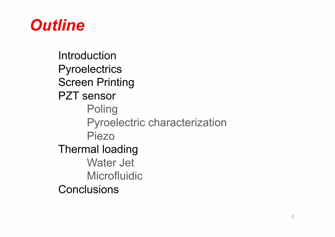
Pyroelectrics Ferroelectrics : Internal polarization
Piezoelectrics : Polarization changes with stress
Pyroelectrics : Polarization change with temperature variation
! Measure only temperature variations
Pyro coef. from 30 to 200 ( µC.m-2.K-1) Applications : Bolometers, IR detector, presence detector, fingerprint sensor Terahertz detectors 3&
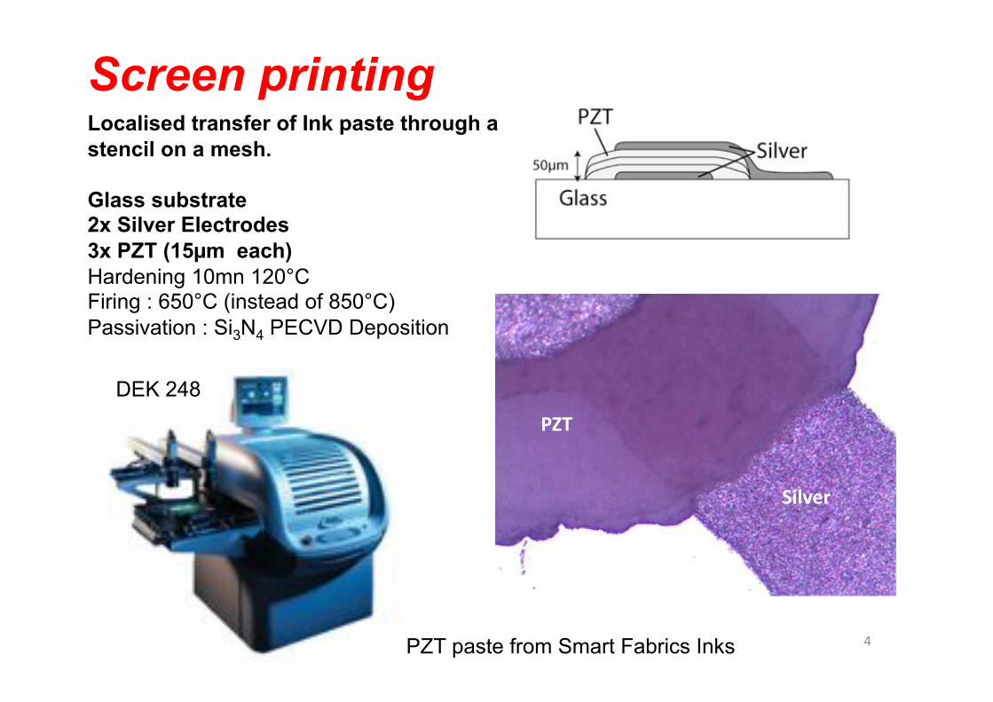
Screen printing Localised transfer of Ink paste through a stencil on a mesh.
Glass substrate 2x Silver Electrodes 3x PZT (15µm each) Hardening 10mn 120°C Firing : 650°C (instead of 850°C) Passivation : Si3N4 PECVD Deposition
DEK 248
PZT paste from Smart Fabrics Inks
PZT$
Silver$
4&

Screen printing
Surface 8mm2
5&
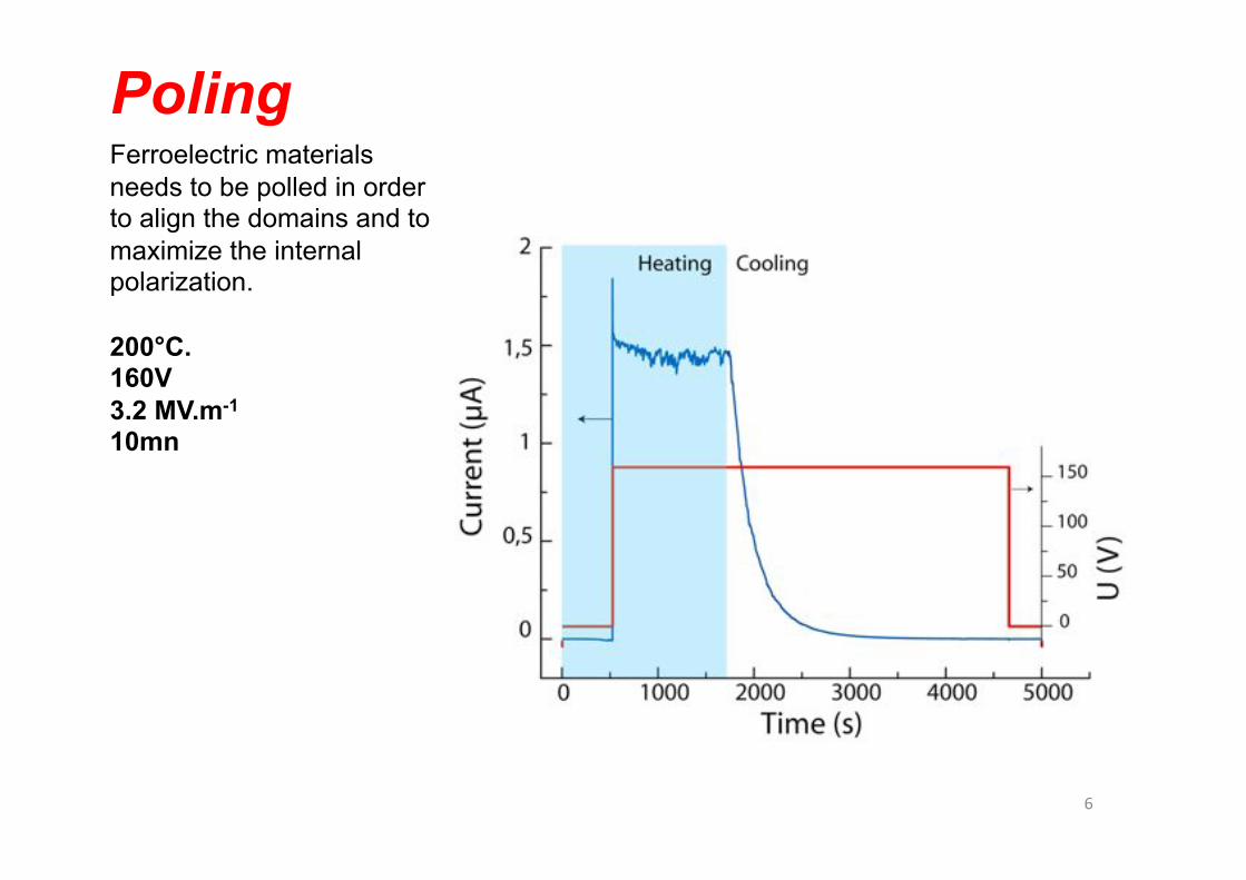
Ferroelectric materials needs to be polled in order to align the domains and to maximize the internal polarization.
200°C. 160V 3.2 MV.m-1 10mn
Poling
6&
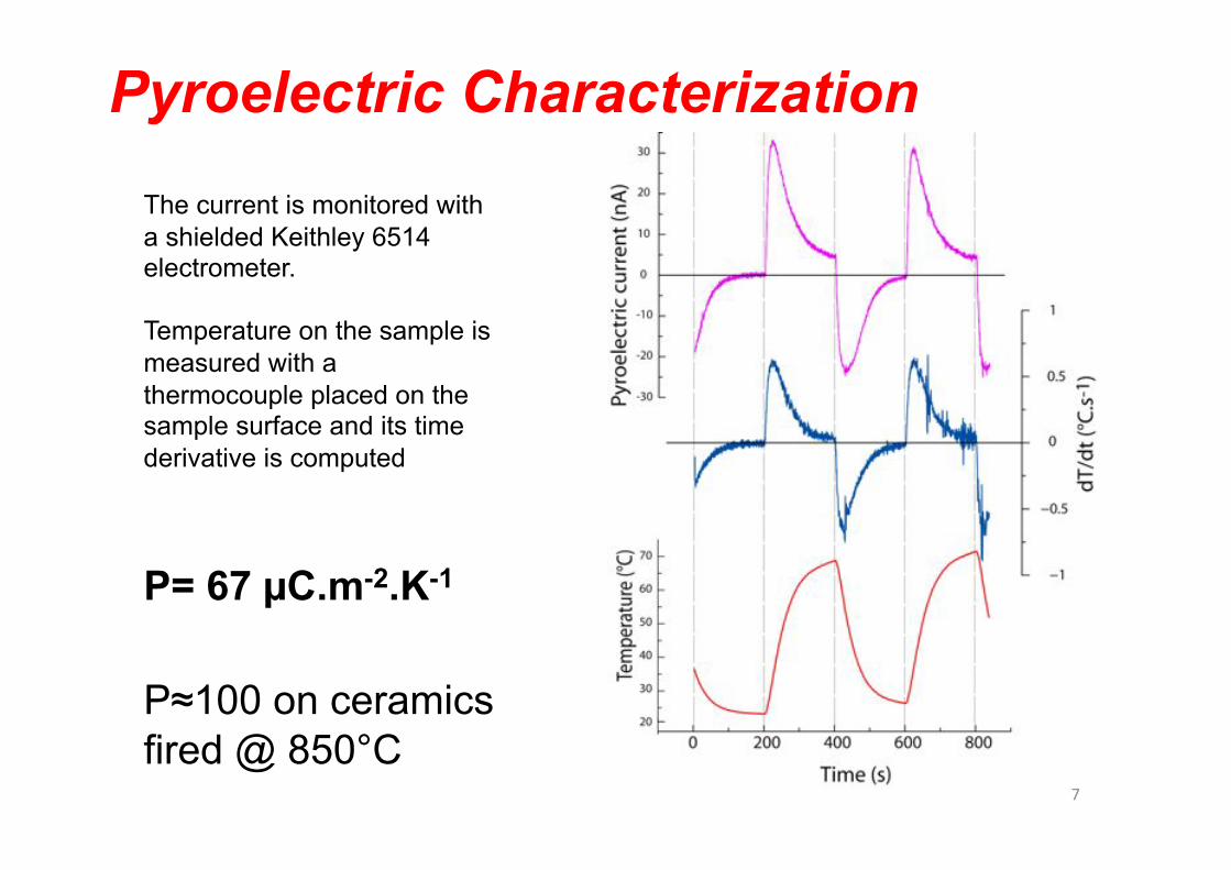
Pyroelectric Characterization
The current is monitored with a shielded Keithley 6514 electrometer.
Temperature on the sample is measured with a thermocouple placed on the sample surface and its time derivative is computed
P= 67 µC.m-2.K-1
P≈100 on ceramics fired @ 850°C
7&

Piezoelectric Mechanical oscillations on natural frequency Measured with the piezo effect Mechanical escapemement
- Different clamping position, different resonant frequency - Damping
Output plugged on a transimpedance amplifier with a gain of 106 .
8&

Water Jet Thermal Stimulation with jet of hot and cold water
Backside Frontside
9&

Microfluidic
PDMS bloc with a single channel / inlet /outlet
O2 plasma bonding permanent bonding Or mechanical clamping
Syringe pushers connected to inlet with a T junction
3mmx1mm cross section
Microfluidic channel aligned on top of Pyroelectric element
10&

Sequential streams for Temperature gradients
Heat losses :
Water to water Water to glass Water to PDMS
For high pyroelectric current : High DT High flow speed / small Dt
Shortest path
0°C& 80°C&
11&
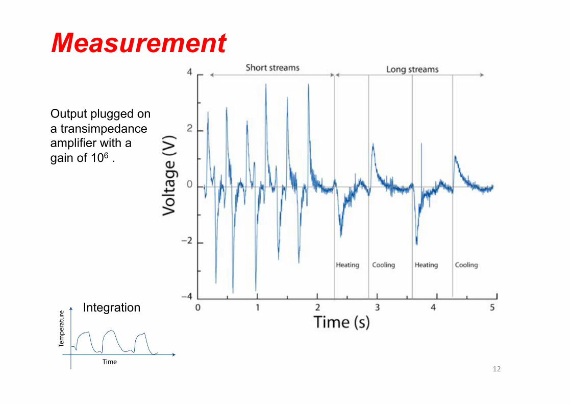
Measurement
Output plugged on a transimpedance amplifier with a gain of 106 .
Integration
12&
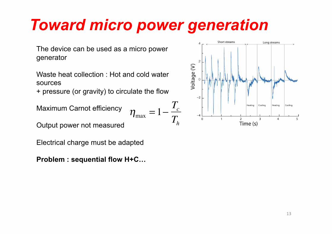
Toward micro power generation
�
ηmax = 1−TcTh
The device can be used as a micro power generator
Waste heat collection : Hot and cold water sources + pressure (or gravity) to circulate the flow
Maximum Carnot efficiency
Output power not measured
Electrical charge must be adapted
Problem : sequential flow H+C…
13&
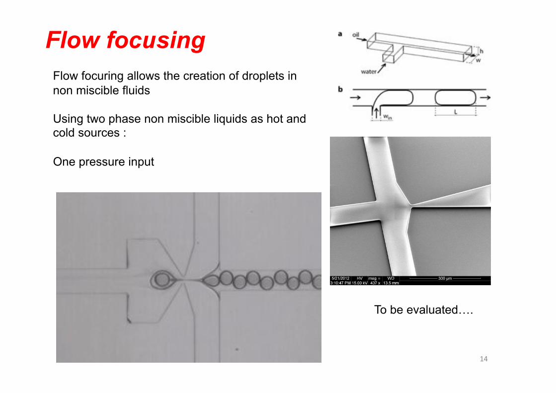
Flow focusing Flow focuring allows the creation of droplets in non miscible fluids
Using two phase non miscible liquids as hot and cold sources :
One pressure input
To be evaluated….
14&

Conclusions
PZT thick film screen printed on glass
Pyroelectric and Piezoelectric behaviour
Streams of consecutive hot and cold water fed through a microfluidic channel
Positive and negative pulses -> pyroelectric current
Potential use in waste heat micro power generation
Optimisation : Material coefficient Substrate (losses) non miscible liquids (one pressure source)
15&