Embed Size (px)
Citation preview
Pyhäsalmi Volcanogenic Massive Sulfide
Deposit, Central Finland
Jesse Hettula
UNIVERSITY OF OULU
GEOSCIENCES
October 2017
2369969
Table of Contents
1. SUMMARY .......................................................................................................................... 1
2. INTRODUCTION ................................................................................................................ 1
3. VOLCANOGENIC MASSIVE SULFIDES ......................................................................... 2
3.1 Definition ....................................................................................................................... 2
3.2 VMS model .................................................................................................................... 2
3.3 Alteration zones and their interpretation for mineral deposit exploration ................. 4
3.4 Metal zonation within mound-type massive sulphide .................................................. 8
3.5 Hydrothermal fluid plumes in seawater ..................................................................... 10
3.6 Classification of VMS deposits .................................................................................... 11
4. REGIONAL GEOLOGY OF THE PYHÄSALMI MINE .................................................. 14
5. PYHÄSALMI MINE .......................................................................................................... 17
6. PYHÄSALMI ORE DEPOSIT DEFORMATION PHASES AND STRATIGRAPHY .... 17
7. MODELS AND THEORIES ON HOW THE PYHÄSALMI DEPOSIT FORMED ......... 20
8. DISCUSSION ..................................................................................................................... 23
9. REFERENCES .................................................................................................................... 24
1
1. SUMMARY
Pyhäsalmi mine is located in central Finland, at the eastern side of the Pyhäjärvi lake.
The Pyhäsalmi deposit is polymetallic Zn-Cu VMS ore body with total reserve, mined
and yet to be mined, of 58.3 Mt @ Cu 0.9 %, Zn 2.4 %, S 37.8 %, Au 0.4 g/t and Ag 14
g/t. At the end of 2013, 51 Mt of ore has been mined. The mine will be in operation
until August of 2019.
The Pyhäsalmi deposit is hosted in a felsic-dominated bimodal Proterozoic succession.
Local hydrothermal alteration is composed of sericite-quartz alteration, and intensifies
when it is in close proximity with the upper ore body. The deep ore body is thrusted into
unaltered metamorphosed hangingwall volcanic rock, thus separated from the alteration
zone.
The Pyhäsalmi district and deposit has been subjected to four different tectonic phases
(D1 – D4) and intrusions accompanied by them. These tectonic processes have thrusted
the deposit in upright position from the original position.
Basic theory of VMS formation processes can be used for modeling Pyhäsalmi deposit
formation process, which in turn can benefit massive sulfide exploration.
2. INTRODUCTION
The purpose of this Bachelor´s thesis is to introduce basic concepts of volcanogenic
massive sulfides (VMS) and Pyhäsalmi deposit, central Finland. This thesis explains
what the VMS deposits are, how they form, how they may be classified and what
methods are effective for VMS exploration. This subject was chosen as a preliminary
study for later work on Pyhäsalmi deposits alteration zones.
The Pyhäsalmi deposit was discovered in 1958. Pyhäsalmi mine started to operate from
year 1962 onwards. From the very beginning, study of the Pyhäsalmi mine area has
taken place by intensive drilling and geochemical sampling. Mainly by these methods,
there has been some success at explaining how Pyhäsalmi deposit formed.
2
3. VOLCANOGENIC MASSIVE SULFIDES
3.1 Definition
Volcanogenic massive sulfides (VMS) or volcanic-hosted massive sulfides (VHMS) are
stratabound or stratiform massive bodies of sulfide ore and other accessory minerals.
Massive sulfide deposits consist of >60% of sulfides. VMS deposits form at or just
below the sea floor in any relatively deep submarine environments from seawater
derived hydrothermal fluids that are driven by convective circulation above a deep heat
source, which is most commonly a magma chamber (Hannington, 2014).
Most often submarine massive sulfide ore precipitates on top of volcanic footwall rocks,
and more rarely into turbidites or other such deep – sea sedimentary rocks that are
mixed with volcanic rocks. VMS deposits appear in several different marine volcanic
settings, usually in zones of extension and active volcanism along mid-ocean ridges, but
also at island arcs, back-arc basins and fore-arc troughs. VMS deposits are forming
today on the seafloor around undersea volcanoes (Robb, 2005).
3.2 VMS model
VMS deposits form because of convective hydrothermal circulation within the footwall.
Convective hydrothermal systems require both a heat source and high footwall
permeability to allow effective fluid flow and depth for circulation. Heat enables
convection; thus, a magma body is needed within a few kilometers of the seafloor. The
temperature of the hydrothermal fluids can vary from 400 °C to just a few decrees
higher than ambient seawater. In terms of ore forming processes, higher temperature is
better since mineral and ligand solubility in aqueous solutions increases with
temperature. High-temperature hydrothermal fluids (>300 °C) are generally saline (7
wt. % NaCl), acidic (pH 4 – 6), reducing, rich in H2S and metals such as Fe, Mn, Pb, Zn
and Cu. Low temperature hydrothermal fluids have salinities up to twice that of modern
3
seawater (3,2 wt. % NaCl) and are a mix of hydrothermal fluids and pore water.
Seawater itself is cold (2 °C), alkaline, neutral (pH 7-8), oxidizing and rich in SO4, but
poor in metals (Robb, 2005).
In VMS hydrothermal systems, the hydrothermal fluids for the most part originate from
seawater. Fluids seep down from the seafloor towards the magma chamber, close in to
the chambers proximity and, when the fluid is hot enough, the fluid flow direction turns
up towards the ocean floor. During this circulation, the fluids flow through the oceanic
crust, scavenging metals while gradually increase the fluids metal ion content. The
source of sulfur is essentially from the sulfate component of the seawater itself with
reduction of sulfate to sulfide during fluid-rock interaction prior to venting. It is
possible that some of the hydrothermal fluids originate from the magma, yet there are
not any good general estimates on how much magmatic fluids can affect the overall ore
forming process (Robb, 2005).
Fractures, faults or other anomalies which create permeability in the footwall rock act as
a structural control to focus the fluid flow when high temperature fluids begin to rise to
the seafloor. After effective fluid discharge control has formed, an efficient means of
precipitating solids from the discharging fluids are needed. In general, precipitation
happens by mixing of hot hydrothermal fluid with cold ambient seawater. This lowers
the hydrothermal fluids temperature, makes it more oxidized and less saline. As a result,
the hydrothermal fluid becomes less capable to solute metals. Because ore mineral
precipitation happens rapidly and in a small area, it is possible that mineral deposit can
form just above or at the fluid discharge site. When the solids have precipitated from the
fluid and the fluid venting has stopped, a cover of volcanic or sedimentary material is
needed to protect the ore deposit from oxidation and erosion (Large, 1992).
Hydrothermal circulation leaves behind large alteration zones around the hydrothermal
venting system as a proof of activity. Hydrothermal alteration can be seen up to 20 km
laterally around some deposit, and 2 -4 km deep below the massive sulfide lens. It is
most intense in and around the upflow zone through which hydrothermal fluids rise to
surface, forming a characteristic assemblage of magnesian-chlorite-quartz-pyrite
minerals. Sericite gradually replaces chlorite as the dominant alteration mineral with
increasing distance. In the far-field alteration zone, alteration is much less intense, and
is characterized by sericite, chlorite and epidote (Ridley, 2013). Usually, VMS related
4
regional alteration is hard to differentiate from diagenesis and/or regional
metamorphism (Large, 1992).
When sulfides start to precipitate from the hydrothermal fluid, zoned structures of
mounds, sheets and/or pipes will form. Pyrite is the most common sulphide mineral in
the massive sulfide, followed by pyrrhotite, chalcopyrite, sphalerite, galena and, more
rarely, sulphosalts and bornite. The most common non-sulphide minerals include
magnetite, hematite and cassiterite. In VMS deposits, quartz, chlorite, barite, gypsum
and carbonates are ganque minerals (Lydon, 1984).
The amount of the Cu, Zn, Pb and Fe in hydrothermal solution is strongly temperature-
dependent. Rapid increases in concentration occur above 310°C for Zn and 320°C for
Cu and Fe. The small difference (10°C) in this divide for Cu and Zn appears to be
sufficient to cause the observed zoning from Cu to Zn sulfides outward from the high-
temperature interior to the low-temperature exterior of a growing chimney or mound
(Large, 1992).
Temperature differences effectively separate vigorous, metal sulfide-precipitating, high-
temperature black smokers (300 – 400°C) from low-temperature anhydrite-
precipitating, metal-poor, white or gray smokers (200 – 300°C). The color difference
between white and black smokers is caused by the lack of metals in white smokers.
White smokers can evolve into black smokers if the temperature rises above 300°C and
vice versa (Robb, 2005).
Black smokers have the biggest contrast in fluid density when compared to seawater.
Because of this contrast, black smokers exhibit high-velocity (1 – 2 m/s) and turbulent
discharge and produces buoyant hydrothermal plumes that rise well above the seafloor
(Shanks, 2012).
3.3 Alteration zones and their interpretation for mineral deposit exploration
Hydrothermal fluids in the VMS circulation systems breaks down feldspar and volcanic
glass in the primary volcanic footwall host rocks. These minerals are replaced by
sericite, chlorite, carbonate, pyrite, and quartz in varying propositions, depending on the
5
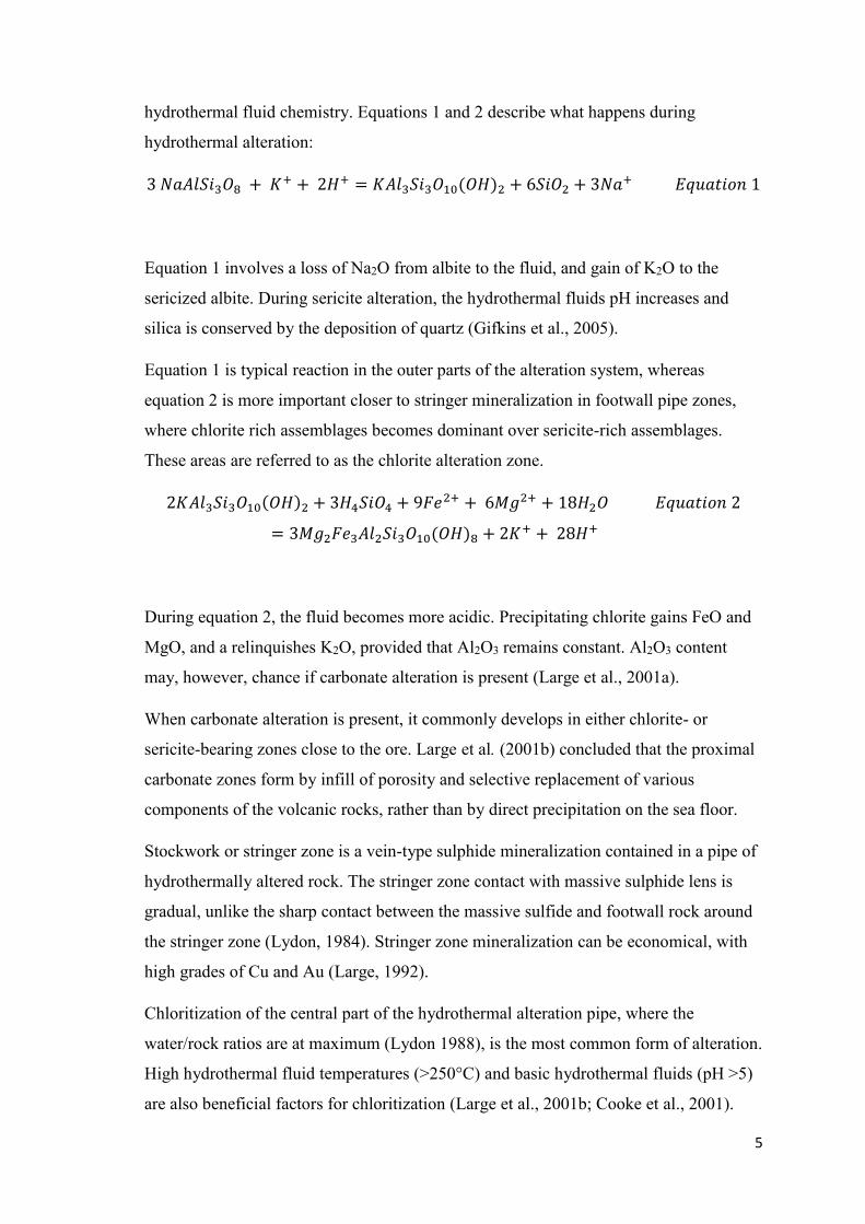
hydrothermal fluid chemistry. Equations 1 and 2 describe what happens during
hydrothermal alteration:
3 𝑁𝑎𝐴𝑙𝑆𝑖3𝑂8 + 𝐾+ + 2𝐻+ = 𝐾𝐴𝑙3𝑆𝑖3𝑂10(𝑂𝐻)2 + 6𝑆𝑖𝑂2 + 3𝑁𝑎+ 𝐸𝑞𝑢𝑎𝑡𝑖𝑜𝑛 1
Equation 1 involves a loss of Na2O from albite to the fluid, and gain of K2O to the
sericized albite. During sericite alteration, the hydrothermal fluids pH increases and
silica is conserved by the deposition of quartz (Gifkins et al., 2005).
Equation 1 is typical reaction in the outer parts of the alteration system, whereas
equation 2 is more important closer to stringer mineralization in footwall pipe zones,
where chlorite rich assemblages becomes dominant over sericite-rich assemblages.
These areas are referred to as the chlorite alteration zone.
2𝐾𝐴𝑙3𝑆𝑖3𝑂10(𝑂𝐻)2 + 3𝐻4𝑆𝑖𝑂4 + 9𝐹𝑒2+ + 6𝑀𝑔2+ + 18𝐻2𝑂 𝐸𝑞𝑢𝑎𝑡𝑖𝑜𝑛 2
= 3𝑀𝑔2𝐹𝑒3𝐴𝑙2𝑆𝑖3𝑂10(𝑂𝐻)8 + 2𝐾+ + 28𝐻+
During equation 2, the fluid becomes more acidic. Precipitating chlorite gains FeO and
MgO, and a relinquishes K2O, provided that Al2O3 remains constant. Al2O3 content
may, however, chance if carbonate alteration is present (Large et al., 2001a).
When carbonate alteration is present, it commonly develops in either chlorite- or
sericite-bearing zones close to the ore. Large et al. (2001b) concluded that the proximal
carbonate zones form by infill of porosity and selective replacement of various
components of the volcanic rocks, rather than by direct precipitation on the sea floor.
Stockwork or stringer zone is a vein-type sulphide mineralization contained in a pipe of
hydrothermally altered rock. The stringer zone contact with massive sulphide lens is
gradual, unlike the sharp contact between the massive sulfide and footwall rock around
the stringer zone (Lydon, 1984). Stringer zone mineralization can be economical, with
high grades of Cu and Au (Large, 1992).
Chloritization of the central part of the hydrothermal alteration pipe, where the
water/rock ratios are at maximum (Lydon 1988), is the most common form of alteration.
High hydrothermal fluid temperatures (>250°C) and basic hydrothermal fluids (pH >5)
are also beneficial factors for chloritization (Large et al., 2001b; Cooke et al., 2001).
6
Chlorite alteration zones are dominated by chlorite (50 wt% - 80 wt%) with subordinate
quartz + pyrite + sericite ± carbonate. A slight Cu enrichment is common in chlorite
alteration zone, when compared to sericite alteration zone (Gifkins et al., 2005).
The upper central part of the hydrothermal alteration pipe can also be dominated by
silicification. These cores are composed of quartz + pyrite and quartz + pyrite + sericite
± chlorite assemblages (Gifkins et al., 2005). In siliceous core zones, hydrothermal
alteration has been most intense, where hydrothermal fluid flow and temperature are at
their highest, destroying all primary textures of the host rock. The core is commonly
intersected by networks of pyrite + chalcopyrite stringer veins. When present, siliceous
core is formed by supersaturation of Si in the hydrothermal fluid. It is surrounded by
chlorite alteration.
Usually these chlorite alteration zones are surrounded by an outer zone of K2O
enrichment (sericite alteration zone) (Lydon, 1984). Sericite alteration forms in lower
temperatures and slightly acidic fluids (Large et al., 2001b; Cooke et al., 2001), forming
assemblages of sericite + chlorite + quartz + carbonate + pyrite. Minor disseminated
sphalerite may be present in sericite alteration zone (Gifkins et al., 2005).
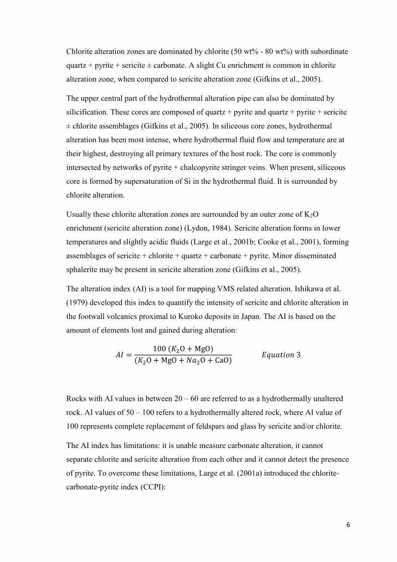
The alteration index (AI) is a tool for mapping VMS related alteration. Ishikawa et al.
(1979) developed this index to quantify the intensity of sericite and chlorite alteration in
the footwall volcanics proximal to Kuroko deposits in Japan. The AI is based on the
amount of elements lost and gained during alteration:
𝐴𝐼 =100 (𝐾2O + MgO)
(𝐾2O + MgO + 𝑁𝑎2O + CaO) 𝐸𝑞𝑢𝑎𝑡𝑖𝑜𝑛 3
Rocks with AI values in between 20 – 60 are referred to as a hydrothermally unaltered
rock. AI values of 50 – 100 refers to a hydrothermally altered rock, where AI value of
100 represents complete replacement of feldspars and glass by sericite and/or chlorite.
The AI index has limitations: it is unable measure carbonate alteration, it cannot
separate chlorite and sericite alteration from each other and it cannot detect the presence
of pyrite. To overcome these limitations, Large et al. (2001a) introduced the chlorite-
carbonate-pyrite index (CCPI):
7
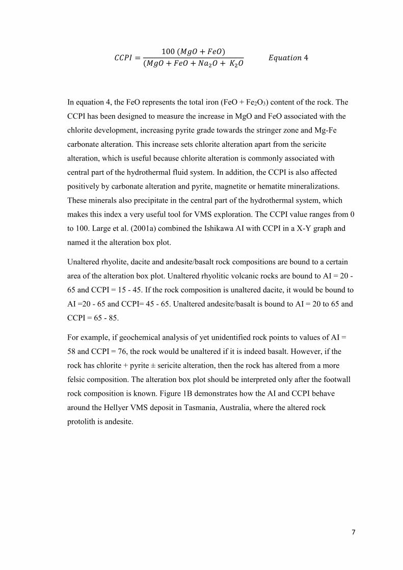
𝐶𝐶𝑃𝐼 =100 (𝑀𝑔𝑂 + 𝐹𝑒𝑂)
(𝑀𝑔𝑂 + 𝐹𝑒𝑂 + 𝑁𝑎2𝑂 + 𝐾2𝑂 𝐸𝑞𝑢𝑎𝑡𝑖𝑜𝑛 4
In equation 4, the FeO represents the total iron (FeO + Fe2O3) content of the rock. The
CCPI has been designed to measure the increase in MgO and FeO associated with the
chlorite development, increasing pyrite grade towards the stringer zone and Mg-Fe
carbonate alteration. This increase sets chlorite alteration apart from the sericite
alteration, which is useful because chlorite alteration is commonly associated with
central part of the hydrothermal fluid system. In addition, the CCPI is also affected
positively by carbonate alteration and pyrite, magnetite or hematite mineralizations.
These minerals also precipitate in the central part of the hydrothermal system, which
makes this index a very useful tool for VMS exploration. The CCPI value ranges from 0
to 100. Large et al. (2001a) combined the Ishikawa AI with CCPI in a X-Y graph and
named it the alteration box plot.
Unaltered rhyolite, dacite and andesite/basalt rock compositions are bound to a certain
area of the alteration box plot. Unaltered rhyolitic volcanic rocks are bound to AI = 20 -
65 and CCPI = 15 - 45. If the rock composition is unaltered dacite, it would be bound to
AI =20 - 65 and CCPI= 45 - 65. Unaltered andesite/basalt is bound to AI = 20 to 65 and
CCPI = 65 - 85.
For example, if geochemical analysis of yet unidentified rock points to values of AI =
58 and CCPI = 76, the rock would be unaltered if it is indeed basalt. However, if the
rock has chlorite + pyrite ± sericite alteration, then the rock has altered from a more
felsic composition. The alteration box plot should be interpreted only after the footwall
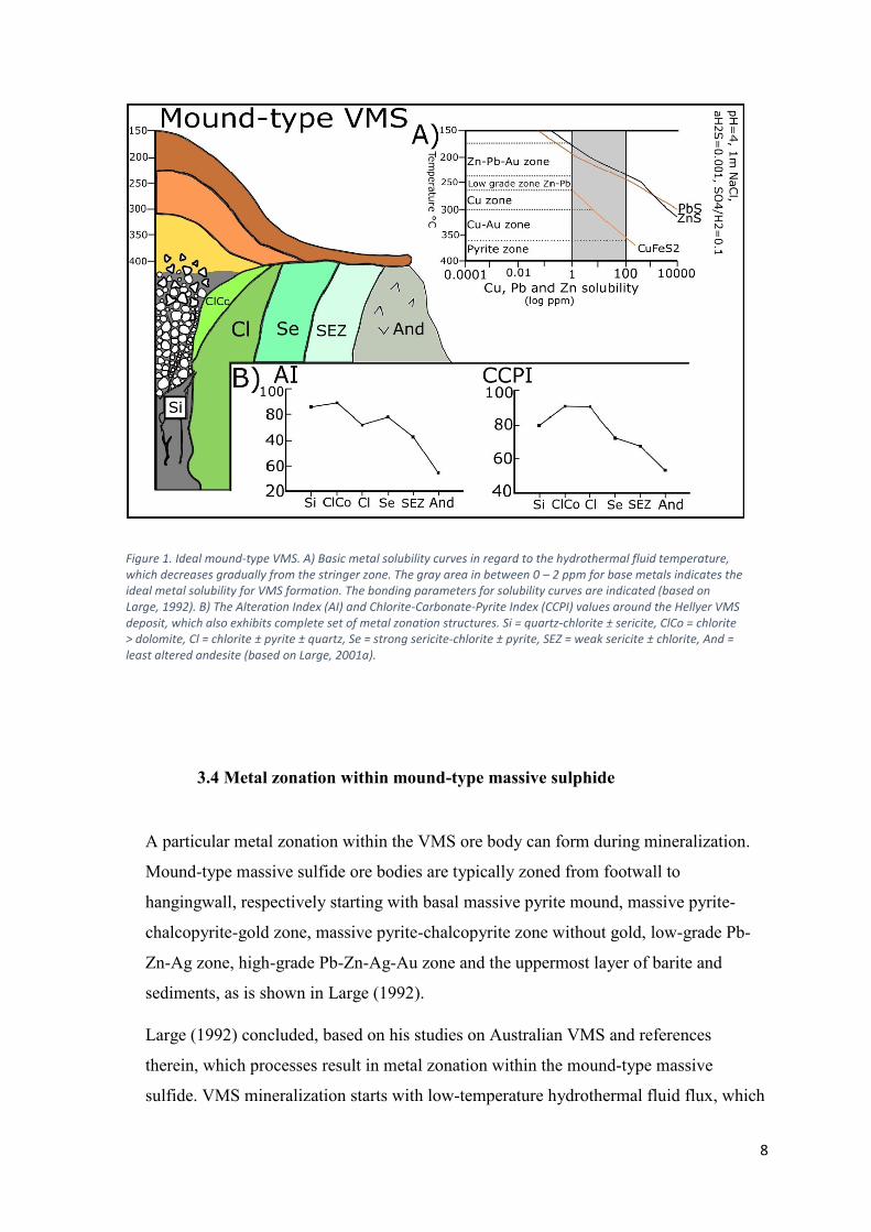
rock composition is known. Figure 1B demonstrates how the AI and CCPI behave
around the Hellyer VMS deposit in Tasmania, Australia, where the altered rock
protolith is andesite.
8
3.4 Metal zonation within mound-type massive sulphide
A particular metal zonation within the VMS ore body can form during mineralization.
Mound-type massive sulfide ore bodies are typically zoned from footwall to
hangingwall, respectively starting with basal massive pyrite mound, massive pyrite-
chalcopyrite-gold zone, massive pyrite-chalcopyrite zone without gold, low-grade Pb-
Zn-Ag zone, high-grade Pb-Zn-Ag-Au zone and the uppermost layer of barite and
sediments, as is shown in Large (1992).
Large (1992) concluded, based on his studies on Australian VMS and references
therein, which processes result in metal zonation within the mound-type massive
sulfide. VMS mineralization starts with low-temperature hydrothermal fluid flux, which
Figure 1. Ideal mound-type VMS. A) Basic metal solubility curves in regard to the hydrothermal fluid temperature, which decreases gradually from the stringer zone. The gray area in between 0 – 2 ppm for base metals indicates the ideal metal solubility for VMS formation. The bonding parameters for solubility curves are indicated (based on Large, 1992). B) The Alteration Index (AI) and Chlorite-Carbonate-Pyrite Index (CCPI) values around the Hellyer VMS deposit, which also exhibits complete set of metal zonation structures. Si = quartz-chlorite ± sericite, ClCo = chlorite > dolomite, Cl = chlorite ± pyrite ± quartz, Se = strong sericite-chlorite ± pyrite, SEZ = weak sericite ± chlorite, And = least altered andesite (based on Large, 2001a).
9
then gradually evolves into 300 - 350°C hydrothermal fluid. Eventually temperature
begins to fall to the point when fluid flux stops completely. Large (1992) divided this
process into four stages, based on differences in sulfide precipitation and solubility.
Temperature regime has a critical control on base and precious metal solubility and
deposition. In the stage 1, when low-temperature hydrothermal fluid (150°-250°C) are
discharged onto the seafloor, copper, lead and zinc are transported in ore-forming
solutions as chloride or bisulfide complexes, depending on the solution chemistry
(Large, 1977). These metals are released from the chloride and bisulfide complexes due
to higher pH and lower temperature of the seawater, which decreases metal solubility.
As a result, copper, iron, zinc and lead begin to precipitate as sulfides in significant
amounts. At the same time, sulfates (barite and anhydrite) may form a layer or cap on
top of the sulfide mound. The sulfates precipitate from the seawater on top of the sulfide
mound as a result of increasing temperature.
During the stage 2, when fluid temperature rises to 250°C and towards 300°C, copper
and gold solubilities have risen significantly, introducing chalcopyrite and native gold
to the massive sulfide mound. At the same time, Pb-Zn-Ag solubility also rises so high
that these metals will not immediately precipitate when temperatures begin to fall. The
high-temperature fluid will solute the previously precipitated galena and sphalerite, and
move them upwards in the sulfide mound, until they precipitate again due to falling
temperatures. This results in a massive Cu ± Au sulfide base upon which lies massive
low-grade Zn-Pb-Ag-Ba sulfide. The uppermost layer of the mineralization constitutes
of sulfate.
Continued input of high-temperature fluids (300° to 350°C, stage 3) shapes the stringer
zone to more clearly defined form. Chalcopyrite and pyrite precipitates in the stringer
zone and in the basal part of the mound “pushing” the Zn-Pb zone upwards with the
same principle that was explained before. The transition zone in between is low grade
Zn-Pb-Ag massive sulfide, which probably represents an interval of lead and zinc
leaching between the chalcopyrite front and the upper zone of lead-zinc deposition (Fig.
1A). If the hydrothermal fluid temperature rises above 350°C, all metal solubility will
rise so high that the fluid will be grossly undersaturated and it will solute all but pyrite
as it enters to the massive ore. Pyrite alone will continue to replace earlier precipitates
on top of the stringer zone to form massive pyrite zone. All other zones will move
10
upwards, all the while enriching the metal grade of topmost Pb-Zn-Ag-Au zone even
further. This process is referred to as zone refining.
At this temperature regime during stage 3, gold is at first carried by chloride (AuCl2-)
complex to the stringer zone and massive pyrite-chalcopyrite zone. Gold solubility
gradually decreases due to falling temperatures along the way, which forces gold to
precipitate. Switchover from AuCl2- to Au(HS)2
- transport happens at low grade Zn-Pb-
Ag zone because of change in hydrothermal fluid chemistry. The bisulfide complexes
will then leach gold from the middle zones of the porous massive sulfide. Gold is then
carried from the middle zones to the uppermost Zn-Pb-Ag-Au-Ba zone by bisulfide
complexes, where gold precipitates again due to mixing with seawater.
During stage 4 of VMS hydrothermal activity, the fluid temperature falls, and while
doing so, the low temperature fluid will move through the massive sulfide. It
precipitates late-stage sphalerite, galena, barite and carbonate veins which will
somewhat overprint the earlier mineralizations in all zones.
In addition to the temperature control on the development of these zones, metal
solubility is also affected by the hydrothermal fluids pH, salinity and ƒO2. These values
vary from deposit to deposit and are affected by footwall geochemistry and
hydrothermal fluids origin. A complete zonation pattern is typically developed in
mound-style VMS. Other VMS deposit types, such as sheets, pipes and stacks of bodies
often exhibit distinctive characteristics.
3.5 Hydrothermal fluid plumes in seawater
Hydrothermal fluid behavior in seawater is mainly governed by the density of the
hydrothermal fluid, and the density is affected by salinity and temperature variation of
the hydrothermal fluid. Fluid salinity will increase the density, whereas higher
temperatures will lower it. In a situation where high-temperature, low salinity
hydrothermal fluid encounters seawater, the fluid will be less dense than the seawater.
This difference causes the hydrothermal fluid to be buoyant. Thus, hydrothermal fluids
will rise and spread as a column towards the ocean surface. It will not, however rise too
11
high because the “black smoke” will rapidly cool down and mix with seawater, causing
the hydrothermal fluid density to increase. When hydrothermal fluids density is equal to
the seawater, hydrothermal fluid forms a stratigraphic layer in the sea, where it will
remain until it has assimilated into the seawater (Sato, 1972).
These hydrothermal fluids will appear as a black smoke – hence the name for black
smokers. The fluid appears black because of sheer amount of precipitating tiny sulfide
particles in the hydrothermal fluid. After the sulfides precipitate, they will sink down to
the ocean floor and form a sheet-like massive sulphide proximal to the hydrothermal
venting site and metalliferous sediments at more remote areas. Sato (1972) suggested
this method as one of the two models for sheet-like VMS deposit formation.
For Kuroko VMS deposit where the ore body has a sheet-like structure but the
hydrothermal fluids had higher density than seawater, Sato (1972) suggested that the
hydrothermal fluid migrated downslope when encountering seawater. The fluid moved
until it arrived at the lowermost point of local topography, where a brine pool
accumulated. The brine pool remains until it is completely precipitated all its sulfides
and forms a massive sulfide structure that is restricted by local topography. Uneven
topography and density difference between hydrothermal fluid and seawater may
explain why some deposits are not located at the top of central part of hydrothermal
alteration zone. However, the brine pool model is inconsistent with observations from
active seafloor hydrothermal system. The only modern analogies for the brine pool
model are in the Red Sea (Shanks, 2012)
3.6 Classification of VMS deposits
VMS deposits have been classified by using criteria such as base metal content
(Solomon, 1976; Franklin et al., 1981; Large, 1992), tectonic setting (Sawkins, 1976),
host rock textures (Morton and Franklin, 1987), host rock lithology (Sangster and Scott,
1976) and host rock composition (Barrie and Hannington, 1997; Franklin et al., 2005;
Galley et al., 2007). Since most of the metals in VMS deposits are derived from
leaching of the footwall rock (Large, 1992), and the footwall composition is somewhat
12
controlled by tectonic setting, there tends to be some overlap and common agreement
between these classification schemes.
Because all VMS deposits are polymetallic, Franklin et al. (1981) classified them into
two kinds of base metal groups, the Zn-Pb-Cu group and Cu-Zn group. He observed
unifying features within these groups, namely in the footwall compositions and
alteration features.
The Zn-Pb-Cu group is hosted by felsic volcanic rocks and/or sedimentary rocks. This
group shows alteration halos that are well defined and laterally extensive, usually with
sericite-quartz core and Mg-rich chlorite halo. Cu-Zn group deposits are, on the other
hand, hosted by mafic volcanic rocks, and subvolcanic intrusions are common.
Alteration zones are well defined and vertically extensive, but they are the opposite to
the Zn-Pb-Cu groups: The core is Mg- rich chlorite which is surrounded by sericite +
quartz- rich halo.
Barrie and Hannington (1999) introduced a new classification scheme for VMS deposit.
Their idea took Franklin et al. (1981) observations a step further, and divided VMS
deposits into five groups. These groups differ from each other by their host rock
compositions, with emphasis on the pre-alteration composition of volcanic host rocks.
The names for these groups are mafic, bimodal-mafic, mafic-siliciclastic, bimodal-felsic
and bimodal siliciclastic. These groups host rock compositions change gradually from
mafic dominated host rocks to felsic dominated host rocks and sediments. Barrie and
Hannington (1999) concluded that by using this classification scheme, they also
effectively grouped different VMS deposits by their time of deposition, volcanic setting,
base metal content, tonnage and grade of the deposits. However, their scheme also had
some inconsistencies when this scheme was used to classify VMS districts instead of
individual VMS deposits (Franklin et al., 2005).
Franklin et al. (2005) modified Barrie and Hanningtons (1999) classification system by
slightly changing the terminology and definition of different VMS settings to better
reflect the relative amounts and compositions of volcanic and sedimentary strata. The
updated group names and definitions are as follows:
1. Back-arc mafic type. The host rock composition is predominately mafic, which
has formed in mature intra-oceanic back-arc setting. Stratigraphic succession
contains ophiolite and ophiolite-like assemblages, dominated by pillowed and
13
massive tholeiitic basaltic flows. When compared to all other deposit types,
back-arc mafic type is Cu rich and Zn poor, small in number of deposits and
size. They are found almost exclusively in Phanerozoic rocks.
2. Bimodal-mafic type. The host rock succession is basalt dominated that can
contain less than 25% felsic volcanic strata. However, deposits are often hosted
by these felsic rocks. Bimodal mafic types tectonic settings are primitive arc or
primitive volcanic arc. These deposits predominate in Late Archean and Early
Proterozoic rocks, and they are the most common of VMS deposit types. They
have the second highest Cu content of these five groups.
3. Pelitic-mafic type. The host rock is composed of sub-equal proportions of mafic
volcanic or intrusive rocks and sedimentary rocks, while felsic volcanic rocks
are minor or absent. Principally they are of Middle Proterozoic age and younger,
and they can form in mature back-arc settings. This type of deposits are less
numerous than the deposits of other types, but their average tonnage is second
only to the felsic siliciclastic type deposits.
4. Bimodal-felsic. The host rock is dominated (35-70%) by felsic volcanic rocks
and it is accompanied by basalts (20-50%) and terrigenous sedimentary rocks
(~10%). Bimodal-felsic type VMS deposits form in continental margin arcs and
related back-arc settings. They are most abundant in Phanerozoic rocks, but
occurs also in Late Archean and Early Proterozoic rocks. These deposits are the
second-most numerous, and on average contain the most Zn and Ag of the five
deposit types. They also commonly contain barite.
5. Felsic-siliciclastic type. The host rock composition contains minor amounts of
felsic and mafic volcanic rocks, of which felsic rocks are commonly more
abundant, and they are dominated by siliciclastic felsic rocks. These deposits
form in mature continental back-arc settings, of which the majority is dated to
Phanerozoic age. Felsic-siliciclastic VMS deposits represent the greatest tonnage
of the VMS types, and they have the largest average deposit size. They have on
average the lowest Cu content and the highest Pb content of the five deposit
types.
Galley et al. (2007) later added a sixth group:
6. Hybrid bimodal-felsic type. This group was added to represent a cross between
VMS and shallow-water epithermal mineralization. They resemble bimodal-
14
felsic type deposits, but contain shallow-water epithermal features, such as
aluminous alteration assemblages and precious metal enrichments.
4. REGIONAL GEOLOGY OF THE PYHÄSALMI MINE
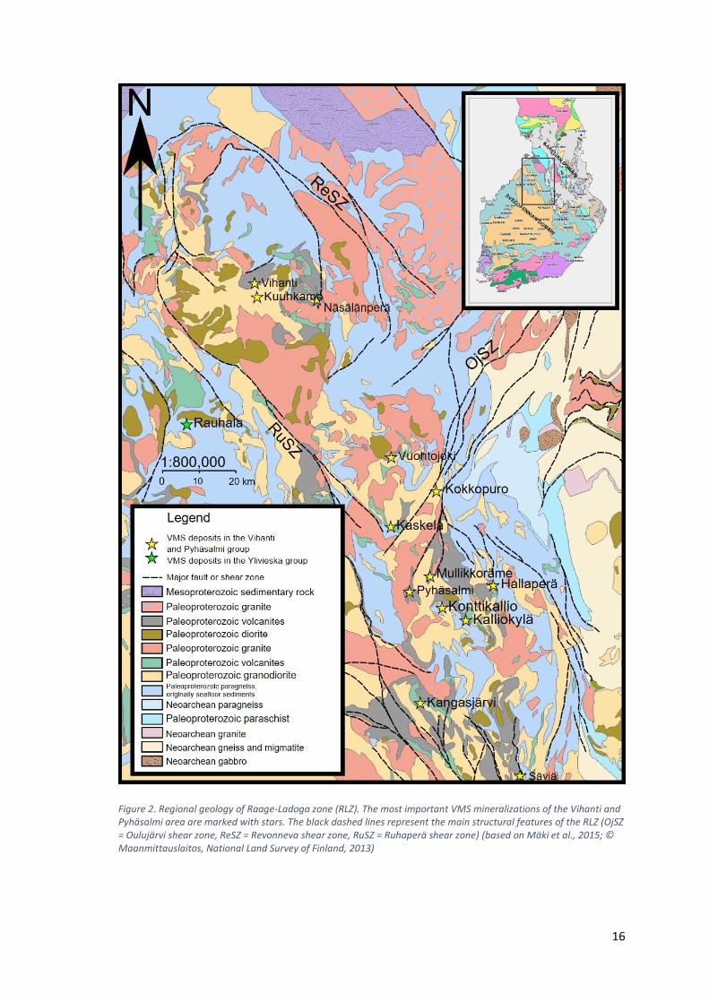
The Pyhäsalmi VMS ore body is hosted by bimodal-felsic volcano-sedimentary rocks
that are genetically related to a 1.93-1.92 Ga Paleoproterozoic island arc. The island arc
formed on an oceanic plate, at the western side of the Archean basement complex. The
oceanic plate later collided with the Archean basement (Korsman, 1988), forming a
major thrust zone. The major thrust zone has reactivated several times during later
orogenic movements. This zone is referred to as the Raahe-Ladoga zone (RLZ), and it
hosts numerous VMS deposits, which can be seen in figure 2 (Mäki, 1986; Laine, 2015;
Mäki et al., 2015). Mineralizations are typically found in the specific lithological
associations (Laine et al., 2015).
The Pyhäsalmi deposit is the main deposit in its own stratigraphic group, which is called
The Pyhäsalmi group. It has several satellite deposits, namely Mullikkoräme,
Ruostesuo, Kangasjärvi, Hallaperä, Vuohtojoki, Kaskela, Konttikallio and Kokkopuro.
Four of them have been mined out and the rest are uneconomic (Mäki et al., 2015). The
Pyhäsalmi mine is still in operation, producing 1.38 Mt of ore in 2016 (First Quantum
Minerals, 2017).
The other stratigraphic group that contains VMS deposits in RLZ is called the Vihanti
group. It contains one major massive sulfide ore (the Vihanti deposit) and it is
accompanied by three minor uneconomic satellite deposits. The Vihanti mine produced
28.1 Mt of sulfide ore (1.447 Mt Zn, 131 000 t Cu, 103 000 t Pb, 190 t Ag, 3038 kg Au)
from 1954-1992 (Laine et al., 2015, Mäki et al., 2015). The host rock is mainly
composed of thick layers of intermediate and felsic metavolcanic rocks and minor
interstratified mafic metavolcanic rocks with calc-silicate and graphite tuffite
interlayers.
15
These two stratigraphic units are separated by one major southwest-northeast and two
major southeast-northwest trending faults, respectively the Oulujärvi shear zone (OjSZ),
and the Revonneva (ReSZ) and Ruhaperä (RuSZ) shear zones.
Mäki et al. (2015) suggested separate lithostratigraphical classification schemes for
Pyhäsalmi and Vihanti groups, indicating that there were at least two different volcanic
environments in RLZ, despite their similar age of 1.93-1.92 Ga (Kousa et al., 2013).
The Pyhäsalmi group represents a lower bimodal-felsic (mafic-felsic) metavolcanics
sequence whereas the Vihanti groups bimodal-felsic (intermediate-felsic) metavolcanic
host rock was deposited during continuous evolution of the arc.
Beyond the south-west border of the RLZ, the bedrock is composed of the Svecofennian
Central Finland Granitoid Complex (1.89-1.87 Ga).
16
Figure 2. Regional geology of Raage-Ladoga zone (RLZ). The most important VMS mineralizations of the Vihanti and Pyhäsalmi area are marked with stars. The black dashed lines represent the main structural features of the RLZ (OjSZ = Oulujärvi shear zone, ReSZ = Revonneva shear zone, RuSZ = Ruhaperä shear zone) (based on Mäki et al., 2015; © Maanmittauslaitos, National Land Survey of Finland, 2013)
17
5. PYHÄSALMI MINE
The Pyhäsalmi deposit was discovered in August 1958 at the eastern side of the
Pyhäjärvi lake by a local farmer, who was digging a well in his yard (Helovuori, 1979).
After the first reserve estimations were done, the mine construction started in August
1959. Open pit mining commenced on March 1, 1962. Since 1976, all production has
been from the underground mine (Mäki et al., 2015).
The underground mine reached the depth of 1000 m in 1996, and a new ore body was
found underneath the 1000m mark in December of the same year. The decision to build
a mine extension was made in 1998 and completed construction of a 1450 m deep
automated hoisting shaft was done in 2001. Inmet Mining Corporation acquired the
Pyhäsalmi mine in 2002, and in 2013 First Quantum Minerals took over the Inmet
Mining Corporation and also the Pyhäsalmi mine (Mäki et al., 2015).
The total reserve, mined and yet to be mined, of Pyhäsalmi deposit are 58.3 Mt @ Cu
0.9 %, Zn 2.4 %, S 37.8 %, Au 0.4 g/t and Ag 14 g/t (Laine et al., 2015). At the end of
2013, the total production of the mine has been 51 Mt (Mäki et al., 2015) and the total
ore production of 2016 has been 1.38 Mt (First Quantum Minerals, 2017). The
estimated closing date of the mine is during August 2019 (personal comm. with Mikko
Numminen, the acting mine geologist at Pyhäsalmi mine).
6. PYHÄSALMI ORE DEPOSIT DEFORMATION PHASES
AND STRATIGRAPHY
The Pyhäsalmi deposit is hosted within deformed Proterozoic volcanics of the
Svecovennian orogeny. The region has gone through a high degree of deformation,
linked to four compressional phases and several intrusions of both mafic and felsic
composition (Lickorish, 2012; Laine et al., 2015).
According to Laine et al. (2015), the structural evolution of the Vihanti-Pyhäsalmi area
is divided into two major compressional stages, which are separated by extensional
18
phase. The first compressional phase is divided into three different compressional
sequences (D1 – D3) and the second compressional phase has one compressional
sequence (D4). The first compressional phase began approximately 1.91 Ga, by
thrusting and flat lying folding of epicontinental sediment towards NE (D1). During the
D1-D2 phase, Vihanti – Pyhäsalmi volcanic arc most probably collided against the
Archean basement, causing major thrust fault zone between these units. This major
thrust zone has reactivated several times during later orogenic movements and is known
as the Raahe-Ladoga zone (RLZ). Continuous SW-NE compression (D3) resulted in
tectonic thickening and intense folding, which refolded the earlier flat lying structures
into upright position along the RLZ.
During 1.89-1.85 Ga, RLZ was subjected to voluminous intrusive activity along major
faults, due to ceased first compressional phase and starting extensional phase. The
progressive extensional phase caused uplift of granulite facies metamorphic blocks
along the earlier shear zones. The highest peak for metamorphosis has been dated to
1952±2 Ma (U-Pb) at conditions of 600 °C/ 4-5 kb (Korja et al., 1994).
After the extensional stage ended, the second compressional stage (D4) began (1.82-
1.79 Ga). The earlier SW-NE compression was shifted to N-S. It overprinted all the
earlier structures, causing the F3 trending folds to be refolded into large-scale F4 folds.
The D4 stage created the crustal scale, sinistral, SW-NE trending Oulujärvi Shear Zone.
The horsetail system of the shear zone caused intense shearing in the Pyhäsalmi area,
resulting in remobilization of the massive sulphide ores and reactivation of the
Archaean craton shear zones. This was accompanied by large amounts of late granites
and pegmatite intrusions close to the major shear zones between 1.82 and 1.79 Ga.
These intrusions are also present at close contact with the Pyhäsalmi deposit (Mäki et
al., 2015).
The Pyhäsalmi deposit host rock structure is complex. In addition, the host rock
protolith identification is hard and at times impossible (Helovuori, 1979) because of
severe obliteration of primary textures. Whole-rock geochemical analysis is, therefore,
the most reliable method to produce some divisions within the stratigraphy (Lickorish,
2013; Mäki et al., 2015).
The whole-rock geochemical data is used to identify different lithostratigraphical units
by their immobile element ratios. High field strength elements (HFSE), such as Zr, Nb,
19
Y and rare-earth elements (REE), are used as an outline for systematic fractionation
during magma cooling. Since HFSE elements are incompatible and immobile, they
enrich in the magma body as it progressively fractionates to more felsic composition. If
a compatible immobile component such as TiO2 or Al2O3 is plotted against an
incompatible monitor of fractionation such as Zr, the shape of the resulting curve
depends on the fractionation behavior of the individual compatible component (Barrett
& Maclean, 1994).
In a TiO2-Zr plot the fractionation curve has a positive slope from basalt to basaltic-
andesite compositions because of the Fe-Ti enrichment trend typical of tholeiitic rocks.
From andesite to rhyolite tholeiitic compositions, the TiO2-Zr fractionation curve has a
negative (depletion) slope due to titanomagnetite crystallization, but Zr builds up in the
magma. Thus, certain Al/Zr ratios, which are also called immobile element ratios,
represent certain rock composition. This ratio does not change even when the rocks are
subjected to hydrothermal alteration. Instead, the altered rock samples form an
alteration line, which exhibits mass change (loss or gain) in the altered rock. Because
the immobile element ratio does not change during alteration, hydrothermally altered
rocks protolith composition is identifiable even if the primary textures are obliterated
(Barrett & Maclean, 1994).
The Pyhäsalmi deposit is hosted in a volcanic sequence, which is primarily rhyolitic.
Geochemical studies have identified several distinct rhyolitic units, which are referred
to as Rhyolite A, Rhyolite B, and Rhyolite X. The alteration zone is predominately
altered rhyolite, but it also includes altered mafic sills of the Lehto synvolcanic
intrusion, which are also referred to as Mafic A-2 (Mäki et al., 2015). The alteration
zone is composed of intensifying sericite alteration towards the upper ore body.
The hangingwall is typically composed of altered Rhyolite B, but chances above the
mineralization into basic composition (Mafic A-1). The thin Rhyolite X unit is
somewhat reliable indicator for the composition change, since it appears just before
Mafic A-1. The Mafic A-1 is composed of coherent and brecciated tholeiitic mafic
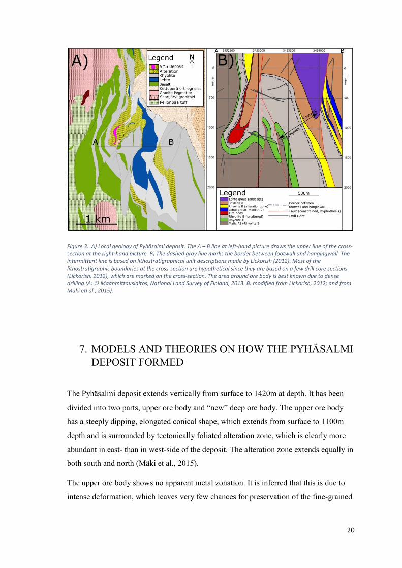
volcanic rocks. Figure 3 shows the local geology of the Pyhäsalmi deposit.
20
Figure 3. A) Local geology of Pyhäsalmi deposit. The A – B line at left-hand picture draws the upper line of the cross-section at the right-hand picture. B) The dashed gray line marks the border between footwall and hangingwall. The intermittent line is based on lithostratigraphical unit descriptions made by Lickorish (2012). Most of the lithostratigraphic boundaries at the cross-section are hypothetical since they are based on a few drill core sections (Lickorish, 2012), which are marked on the cross-section. The area around ore body is best known due to dense drilling (A: © Maanmittauslaitos, National Land Survey of Finland, 2013. B: modified from Lickorish, 2012; and from Mäki etl al., 2015).
7. MODELS AND THEORIES ON HOW THE PYHÄSALMI
DEPOSIT FORMED
The Pyhäsalmi deposit extends vertically from surface to 1420m at depth. It has been
divided into two parts, upper ore body and “new” deep ore body. The upper ore body
has a steeply dipping, elongated conical shape, which extends from surface to 1100m
depth and is surrounded by tectonically foliated alteration zone, which is clearly more
abundant in east- than in west-side of the deposit. The alteration zone extends equally in
both south and north (Mäki et al., 2015).
The upper ore body shows no apparent metal zonation. It is inferred that this is due to
intense deformation, which leaves very few chances for preservation of the fine-grained
21
sulphide assemblages (Imaña, 2003), and post-VMS tectonic stacking of different parts
of the original massive sulfide lens (Mäki et al., 2015).
The deep ore body is comprised of a single piece of massive sulphide with a knob or a
potato-shaped blob (350 x 200 x 300m) and extends between levels 1100 and 1420m. It
is partially enclosed by weakly altered (high Na) volcanic sequence, which is composed
of tectonically banded felsic and mafic schists. This unit is separated from the upper ore
body by a shear zone that contains talc-sericite alteration (Imaña, 2003).
Imaña (2003) described and mapped each of the ore types in the deep ore body and
concluded in his Master’s thesis that the deep ore body, unlike the upper ore body,
shows a typical sulphide and gangue zonation, which consists of a massive inner part
composed of massive pyrite followed by pyrite-chalcopyrite-sphalerite and pyrite-
sphalerite. In terms of Fe, Cu and Zn, the metal zonation is clear. Similarly, the gangue
mineralogy also shows gradual changes from calcite, calcite-dolomite adjacent to the
massive pyrite core, and quartz-calcite-barite, barite-calcite and barite towards the upper
part.
The uppermost pyrite-sphalerite zone does not appear at the top of deep ore body, but in
the bottom and in all sides of the deep ore body. Instead, massive pyrite dominates at
the top and in the center of the deep ore body, and pyrite-chalcopyrite-sphalerite zone is
located in between these two units.
Imaña (2003) also concluded that the sulphide ores were formed by syngenetic sub-
seafloor replacement and deposition near the palaeo-seafloor. Syngenetic subsea-floor
replacement was interpreted to occur within the pyrite dominated zone based on a wide
distribution of colloform and banded carbonate patches along with numerous inclusions
of rapidly emplaced host facies (porphyritic rhyolites and mafic volcanics). These
textures are interpreted as evidence for open space filling and replacement within an
unconsolidated sulphide mound and its underlying volcanic strata at the sub-seafloor
environment. Subseafloor deposition was interpreted to occur at the uppermost layer of
the mineralization. This interpretation is based on the uppermost zinc-layers lack of
altered relicts of its host facies, which suggest that its deposition took place above the
mixing zone of carbonate-sulphate, probably near the paleo-seafloor.
Lickorich (2012) constructed a model of how the Pyhäsalmi deposit may have deformed
from a vertically extensive stratabound structure into the current shape. He used a
22
simplified stratigraphy and drew these stratigraphic units into cross-sections which were
based on the Pyhäsalmi deposit drill-core data, geochemistry data, and dip data derived
from drill-core at the area of 61100N to 63800N. The spacing of the cross-sections is
200m. In these cross-section, Lickorich hypothesized several faults lines based on the
observed lithostratigraphy.
Lickorich (2012) refers to the western margin of the Pyhäsalmi deposit as a hangingwall
structure since the Zn-rich ore is located on the western margin of the deposit. And
since the Zn-rich ore surrounds the deep ore body in all sides but the top, the deposits
current structure may be a result of downward facing sheath-fold with the upper ore-
body forming the upper limb of the fold.
The basic theory of VMS-sulfide formation dictates that the VMS deposit should be
hosted in a zone of alteration. However, at Pyhäsalmi the deep ore body is enclosed by
unaltered volcanic rock. The thrust/shear model for the tectonics of the Pyhäsalmi mine
may provide explanation for this observation. The mineralization has been carried by a
thrust into the overlaying hangingwall, and it also moved a small footwall section from
underneath of the thrusted deep ore body into the deposit, introducing unaltered rock
into the nose of the deposit (Lickorich, 2012).
Laitala (2015) concluded in his Master’s thesis that the Pyhäsalmi area has well defined
pyrrhotite horizons. They are interpreted as metalliferous sediments that are commonly
found both in modern and ancient submarine volcanic sequences that are associated
with the VMS deposits. These pyrrhotite horizons formed in an anoxic and reducing
environment, most likely on the seafloor of a Palaeoproterozoic ocean. The pyrrhotite
horizons mark the tectonic hiatus, where VMS deposits could have had time to form,
and may represent ore horizon equivalents in the stratigraphic succession.
23
8. DISCUSSION
Constructing a model for VMS deposit can be challenging since it is not uncommon for
them to be subjected to deformation and metamorphism during orogeny. In this regard,
the Pyhäsalmi deposit is not an exception.
However, by making correct observations of which lithostratigraphical units belong to
the footwall or the hangingwall during VMS mineralization, it is easier to visualize how
the mineralization has deformed from stratabound structure into its current form.
However, identifying the stratigraphic successions may not always be possible due to
intense deformation and metamorphism. In Pyhäsalmi case, lithostratigraphical unit
identification has been possible due to whole rock geochemistry (immobile element
ratios) and intensive drilling.
The Pyhäsalmi deposit behaves well in the bounds of VMS formation model:
• The footwall composition is bimodal-felsic (according to the classification of
Franklin et al. 2005), and so the footwall alteration should be sericite-quartz
dominated, which is then surrounded by chlorite alteration, which is true for the
most part. However, the chlorite alteration zone appears to be absent.
• The upper ore body can be found by mapping alteration intensity, even though
the deep ore body is not. As it happened, the deep ore body was found by
accident during drilling (personal comm. with Mikko Numminen, the acting
mine geologist at Pyhäsalmi mine).
• The VMS ore body has metal zonation at least in the deep ore body, where Zn
and Cu rich zones are overlaying the massive pyrite.
• At a regional scale sulfide-enriched sediments may represent ore horizon
equivalents in the stratigraphic succession.
By studying the Pyhäsalmi deposit, ore exploration methods in Pyhäsalmi district can be
more effective by focusing on identifying those stratigraphic units that are associated
with VMS formation. However, these methods would not be directly applicable in the
Vihanti district, since the Vihanti districts VMS deposits formed in different
volcanogenic environment.
24
9. REFERENCES
Barrett, T.J., & Maclean, W.H., (1994). Mass changes in hydrothermal alteration zones
associated with VMS deposits of the Noranda area. Exploration Mining Geology, v. 3,
pp. 131 – 160.
Barrie, C. T., & Hannington, M. D., (1999). Classification of volcanic-associated
massive sulfide deposits based on host-rock composition. Reviews in Economic
Geology, v. 8, pp. 1 - 11.
Cooke, D.R., Gemmell, J.B., Large, R.R., (2001). Geochemical modeling of the zone
footwall alteration pipe, Hellyer volcanic-hosted massive sulphide deposit, Western
Tasmania, Australia. Economic Geology, v. 96, pp. 1037 – 1054.
First Quantum Minerals 2017. The page was visited at 30.8.2017.
http://www.first-quantum.com/Our-Business/operating-mines/Pyhasalmi/Production-
Stats/default.aspx
Franklin, J.M., Sangster, D.M., Lydon, J.W., (1981). Volcanic-associated massive
sulfide deposits: Economic Geology 75th Anniversary Volume, pp. 485–627.
Franklin, J. M., Gibson, H. L., Jonasson, I. R., Galley, A. G., (2005). Volcanogenic
massive sulfide deposits. Economic Geology, v. 98, pp. 523 - 560.
Galley, A. G., Hannington, M. D., Jonasson, I. R., (2007). Volcanogenic massive
sulphide deposits. Mineral Deposits of Canada: A Synthesis of Major Deposit-Types,
District Metallogeny, the Evolution of Geological Provinces, and Exploration Methods:
Geological Association of Canada, Mineral Deposits Division, Special Publication, v. 5,
pp. 141-161.
Gifkins, C.C., Herrmann, W., Large, R.R., (2005). Altered volcanic rocks: a guide to
description and interpretation. University of Tasmania. Centre for Ore Deposit
Research. Printing Authority of Tasmania. 275p.
Hannington, M.D., (2014). 13.18 - Volcanogenic Massive Sulfide Deposits. In:
Turekian, K., K. & Holland, H., D. ed. Treatise on Geochemistry (Second Edition).
Elsevier, Oxford, 463 – 488
25
Helovuori, O., (1979). Geology of the Pyhäsalmi Ore Deposti, Finland. Economic
Geology, v. 74. pp. 1084 – 1101.
Imaña, M., (2003). Petrography, mineralogy, geochemistry and 3D modelling of the A
zinc ore in the Pyhäsalmi Zn-Cu VMS deposit, central Finland. Master’s thesis,
University of Turku, Department of Geology and Mineralogy, p. 72.
Ishikawa, Y., Sawaguchi, T., Iwaya, S., and Horiuchi, M., (1976). Delineation of
prospecting targets for Kuroko deposits based on modes of volcanism of underlying
dacite and alteration halos. Mining Geology, v. 26, pp. 105–117 (in Japanese with
English abs.).
Korja, T., Luosto, U., Korman, K., Pajunen, M., (1994). Geophysical and metamorphic
features of Paleoproterozoic Svecofennian orogeny and Palaeoproterozoic overprinting
on Archaean crust. Geological Survey of Finland, Guide 37, pp. 11 – 20.
Korsman, K., (1988) ed. Tectono-metamorphic evolution of the Raahe-Ladoga zone,
eastern Finland. Geological Survey of Finland, Bulletin 343. 96 p.
Kousa, J., Luukas, J., Huhma, H., Mänttäri, I., (2013). Paleoproterozoic 1.93–1.92 Ga
Svecofennian rock units of the Raahe-Ladoga Zone, Central Finland. Geological Survey
of Finland Report of Investigation 198, pp. 91 – 96.
Laitala, J., (2015). Mineralogy and geochemistry of the pyrrhotite horizons in the
Pyhäsalmi district, central Finland. Master’s Thesis, University of Turku, Department of
Geography and Geology, p. 86.
Laine, E., Luukas, J., Mäki, T., Kousa, J., Ruotsalainen, A., Suppala, I., Imaña, M.,
Heinonen, S., Häkkinen, T., (2015). The Vihanti-Pyhäsalmi area. In: Weihed, P., (2015)
ed. 3D, 4D and Predictive modelling of Major Mineral Belts in Europe. Springer
International Publishing Switzerland 2015. Chap. 6, pp. 123 – 144.
Large, R.R., (1977). Chemical evolution and zonation of massive sulfide deposits in
Volcanic Terrains. Economic Geology, v. 72, pp. 549 – 572.
Large, R.R., (1992). Australian Volcanic-Hosted Massive Sulfide Deposits: Features,
Styles, and Genetic Models. Economic Geology, v. 87, pp.471 – 510.
Large, R.R., Gemmell, J.B., Holger, P., (2001a). The Alteration Box Plot: A simple
approach to understanding the relationship between alteration mineralogy and
26
lithogeochemistry associated with volcanic-hosted massive sulfide deposits. Egonomic
Geology, v. 96, pp. 957 – 971.
Large, R.R., McPhie, J., Gemmell, J.B., Herrman, W., Davidson, G.J., (2001b). The
spectrum of ore deposit types, volcanic environments, alteration halos, and related
exploration vectors in submarine volcanic successions: Some examples from Australia.
Economic Geology, v. 96, pp. 913 – 938.
Lickorish, W.H., (2012). Structure of the Pyhäsalmi VMS deposit, Finland.
Unpublished internal report for Pyhäsalmi mine Oy. p. 41.
Lydon, J.W., (1984). Volcanogenic massive sulphide deposits. Part 1: A descriptive
model. Geoscience Canada, v. 11, pp. 195 – 202.
Morton, R.L., Franklin, J.M., (1987). Two-fold classification of Archean volcanic-
associated massive sulfide deposits: Economic Geology, v. 82, pp. 1057–1063.
Mäki, T., (1986). The Lithogeochemistry of the Pyhäsalmi Zn-Cu-Pyrite Deposit,
Finland. In: Prospecting in areas of glaciated terrain symposium, Sept. 1–2, Kuopio.
Finland. Institute of Mining and Metallurgy, London. pp. 69–82
Mäki, T., Imaña, M., Kousa, J., Luukas, J., (2015). The Vihanti-Pyhäsalmi VMS Belt.
In: Maier, W., Lahtinen, R., O´Brien, H., (2015) authored Mineral Deposits of Finland,
1st edition. Elsevier, Inc. Chap. 7, pp. 507 - 530.
Ridley, J., (2013). Ore deposit geology. Cambridge University Press, TJ International
LTD. Padstow Cornwall, 397p.
Robb, L.J., (2005). Introduction to ore – forming processes. Blackwell Publishing,
Blacwell Sicence LTD. 373p.
Sangster, D., Scott, S.D., (1976). Precambrian strata-bound massive Cu-Zn-Pb sulfide
ores of North America, in Wolf, K.H., ed., Handbook of strata-bound and stratiform ore
deposits: Amsterdam, Elsevier, pp. 129–222.
Sato, T., (1972). Behaviours of ore-forming solutions in seawater. Mining geology, v.
22, pp. 31 – 42.
Sawkins, F.J., (1976). Massive sulphide deposits in relation to geotectonics: Geological
Association of Canada Special Paper 14, pp. 221-240.
27
Shanks, W.C., (2012). Theory of deposit formation. In: Shanks, W.C., Thurston, R.,
(2012) edited Volcanogenic massive sulfide occurrence model: U.S. Geological Survey
Scientific Investigations Report 2010–5070–C. Chap. 18, pp. 293 – 298.
Solomon, M., (1976). Volcanic massive sulphide deposits and their host rocks: A
review and an explanation, in Wolf, K.H., ed., Handbook of strata-bound and stratiform
ore deposits, II: Regional studies and specific deposits: Amstedam, Elsevier, pp. 1307–
1328.