Embed Size (px)
Citation preview
PXD DIGITIZER SERIES
OPERATOR’S MANUAL
MARCH 2003

LeCroy Corporation700 Chestnut Ridge RoadChestnut Ridge, NY 10977-6499Tel: (845) 578 6020, Fax: (845) 578 5985
Internet: www.lecroy.com
© 2003 by LeCroy Corporation. All rights reserved.
LeCroy, ActiveDSO, ProBus, SMART Trigger, WavePro, and Waverunner are registered trademarks of LeCroy Corporation. JitterTrack, WaveMaster, and X-Stream are trademarks of LeCroy Corporation. Information in this publication supersedes all earlier versions. Specifications subject to change without notice.
901217-01
Table of Contents
901217-01 ISSUED: March 2003 i
Table of ContentsFirst Things...First................................................................................................1
WHEN YOUR DIGITIZER IS DELIVERED .................................................1Check That You Have Everything..........................................................................1Be Sure To Read This Warranty ............................................................................1Take Advantage Of Maintenance Agreements ......................................................1Obtain Assistance..................................................................................................2Return a Product for Service or Repair..................................................................2Stay Up-to-Date .....................................................................................................2
SAFETY INFORMATION...................................................................3Safety Symbols......................................................................................................3Operating Environment..........................................................................................3Power Requirements .............................................................................................4Cooling Requirements ...........................................................................................4Grounding Requirements.......................................................................................4Calibration .............................................................................................................5Abnormal Conditions .............................................................................................5Cleaning ................................................................................................................5
INSTALL AND POWER UP THE DIGITIZER..............................................6Introduction............................................................................................................6Install NI Software Components ............................................................................6Install PXD Device Driver ......................................................................................7Install the PXI Digitizers.........................................................................................7Install PXD IVI Application Software.................................................................... 11Copy Complementary Files onto Your Hard Drive (optional)...............................15Install PXD IVI Driver ...........................................................................................16Copy Complementary Files onto Your Hard Drive (optional)...............................20Install Complementary files onto Your Hard Drive (optional) ...............................21
Operation............................................................................................................25Introduction..........................................................................................................25Acquisition Modes ...............................................................................................25Trigger Modes......................................................................................................27
PXD SERIES DIGITIZER QUICK START APPLICATION SOFTWARE ...29Soft Front Panel...................................................................................................30
USING THE PXD SERIES DIGITIZER IVI INSTRUMENT DRIVERS ......32PXD Digitizer Specifications......................................................................33
ii ISSUED: March 2003 901217-01
PXD Series Digitizer
BLANK PAGE
901217-01 ISSUED: March 2003 1
WHEN YOUR DIGITIZER IS DELIVERED
CHECK THAT YOU HAVE EVERYTHINGVerify receipt of all items on the packing list or invoice copy. The following is shipped with the stan-dard PXD Series Digitizer:• Performance or Calibration Certificate
• Quick Reference Guide
• CD ROM
Contact the nearest LeCroy customer service center or national distributor if anything is missing or damaged immediately. LeCroy is not responsible for replacement if not contacted immediately.
BE SURE TO READ THIS WARRANTYThe PXD Series Digitizer is warranted for normal use and operation, within specifications, for a period of one year from shipment. LeCroy will either repair or, at LeCroy option, replace any prod-uct returned to one of our authorized service centers within warranty period after verification that the product is found to be defective due to workmanship or materials, and not due to misuse, neglect, accident, or abnormal conditions or operation by the purchaser.Spare and replacement parts, and repairs all have a 90-day warranty.The Digitizer’s firmware has been thoroughly tested and is presumed to be functional. Products not made by LeCroy are covered solely by the warranty of the original equipment manufacturer.
TAKE ADVANTAGE OF MAINTENANCE AGREEMENTSLeCroy offers a variety of services under the heading of Maintenance Agreements. These provide an extended warranty for after the initial one-year warranty has expired. Installation, training, enhancements, and on-site repairs — among other services — are available through special sup-plemental support agreements. Inquire at your LeCroy customer service center or national distrib-utor.
NOTE: The warranty below replaces all other warranties, expressed or implied, including but not limited to any implied warranty of merchantability fitness, or adequacy for any particular purpose or use. LeCroy shall not be liable for any special, incidental, or consequential damages, whether in contract or otherwise. The customer is responsible for the transportation and insurance charges for the return of products to the service facility. LeCroy will return all products under warranty with transport prepaid.
2 ISSUED: March 2003 901217-01
PXD Series Digitizer
OBTAIN ASSISTANCEHelp with installation, calibration, and the use of your PXD Series Digitizer scope in a range of applications is also available from your customer service center.
Transportation charges to the factory are the responsibility of the customer, while products under warranty will be returned with transport prepaid by LeCroy. Outside the warranty period, provide a purchase order number prior to repair or replacement. The customer is responsible for parts and labor related to repair work, and return shipping charges.Prepay return shipments. LeCroy cannot accept COD (Cash On Delivery) or Collect Return ship-ments. We recommend using air freight.
STAY UP-TO-DATETo maintain the PXD Series Digitizer’s performance within specifications, LeCroy recommends calibration at least once a year. LeCroy offers state-of-the-art technology by continually refining and improving the instrument’s capabilities and operation. We frequently update both firmware and software during service, provided free of charge during warranty.
RETURN A PRODUCT FOR SERVICE OR REPAIRIdentify returned LeCroy product(s) by model and serial numbers. Describe the defect or failure, and provide name and contact number. For factory returns, use a Return Authorization Number (RAN), obtainable from customer service. Clearly mark this number on the outside of the shipping package to ensure rapid forwarding within LeCroy. Return those products requiring only maintenance to the nearest customer service center. Defective or damaged products should be returned directly to our factory. Contact our customer service for the return address.
NOTE: Use the original shipping carton when returning Digitizer for repair or replacement. If this is not possible, the carton used should be rigid. The Digitizer should be packed so that it is surrounded by a minimum of four inches (10 cm) of shock absor-bent material.
901217-01 ISSUED: March 2003 3
SAFETY INFORMATION
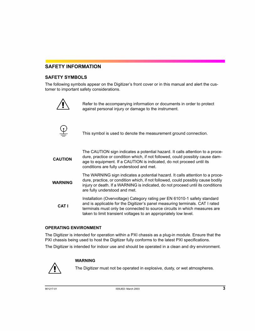
SAFETY SYMBOLSThe following symbols appear on the Digitizer’s front cover or in this manual and alert the cus-tomer to important safety considerations.
OPERATING ENVIRONMENTThe Digitizer is intended for operation within a PXI chassis as a plug-in module. Ensure that the PXI chassis being used to host the Digitizer fully conforms to the latest PXI specifications.The Digitizer is intended for indoor use and should be operated in a clean and dry environment.
Refer to the accompanying information or documents in order to protect against personal injury or damage to the instrument.
This symbol is used to denote the measurement ground connection.
CAUTION
The CAUTION sign indicates a potential hazard. It calls attention to a proce-dure, practice or condition which, if not followed, could possibly cause dam-age to equipment. If a CAUTION is indicated, do not proceed until its conditions are fully understood and met.
WARNING
The WARNING sign indicates a potential hazard. It calls attention to a proce-dure, practice, or condition which, if not followed, could possibly cause bodily injury or death. If a WARNING is indicated, do not proceed until its conditions are fully understood and met.
CAT I
Installation (Overvoltage) Category rating per EN 61010-1 safety standard and is applicable for the Digitizer’s panel measuring terminals. CAT I rated terminals must only be connected to source circuits in which measures are taken to limit transient voltages to an appropriately low level.
WARNING
The Digitizer must not be operated in explosive, dusty, or wet atmospheres.
4 ISSUED: March 2003 901217-01
PXD Series Digitizer
The design of the Digitizer has been verified to conform to EN 61010-1 safety standard per the fol-lowing limits:
Installation (Overvoltage) Category I: Refers to signal level, which is applicable for equipment measuring terminals that are connected to source circuits in which measures are taken to limit transient voltages to an appropriately low level.
Pollution Degree 2: Refers to an operating environment where normally only dry non-conductive pollution occurs. Occasionally a temporary conductivity caused by condensation must be expected.
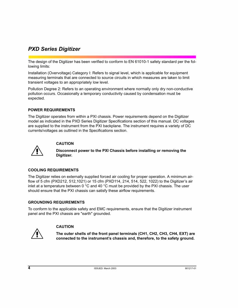
POWER REQUIREMENTSThe Digitizer operates from within a PXI chassis. Power requirements depend on the Digitizer model as indicated in the PXD Series Digitizer Specifications section of this manual. DC voltages are supplied to the instrument from the PXI backplane. The instrument requires a variety of DC currents/voltages as outlined in the Specifications section.
COOLING REQUIREMENTSThe Digitizer relies on externally supplied forced air cooling for proper operation. A minimum air-flow of 5 cfm (PXD212, 512,1021) or 15 cfm (PXD114, 214, 514, 522, 1022) to the Digitizer’s air inlet at a temperature between 0 °C and 40 °C must be provided by the PXI chassis. The user should ensure that the PXI chassis can satisfy these airflow requirements.
GROUNDING REQUIREMENTSTo conform to the applicable safety and EMC requirements, ensure that the Digitizer instrument panel and the PXI chassis are "earth" grounded.
CAUTION
Disconnect power to the PXI Chassis before installing or removing the Digitizer.
CAUTION
The outer shells of the front panel terminals (CH1, CH2, CH3, CH4, EXT) are connected to the instrument’s chassis and, therefore, to the safety ground.
901217-01 ISSUED: March 2003 5
CALIBRATIONThe recommended calibration interval is one year. Calibration should be performed by qualified personnel only.
ABNORMAL CONDITIONSOperate the Digitizer only as intended by the manufacturer. If you suspect the Digitizer has been impaired, remove it from the PXI Chassis and secure against any unintended operation. The Digi-tizer is likely to be impaired, if for example, the instrument fails to perform the intended measure-ments or shows visible damage.
CLEANINGClean only the exterior of the Digitizer, using a damp, soft cloth. Do not use chemicals or abrasive elements. Under no circumstances allow moisture to penetrate the instrument.
WARNING
Any use of the Digitizer in a manner not specified by the manufacturer may impair the instrument and cause an unsafe condition to develop.
CAUTION
No operator serviceable parts inside. Refer servicing to qualified personnel.
6 ISSUED: March 2003 901217-01
PXD Series Digitizer
INSTALL AND POWER UP THE DIGITIZER
INTRODUCTIONPrior to inserting the Digitizer into your chassis, install the necessary software components on your system. The list of components to install depends on the NI components you have already installed:
• If you have LabWindows/CVI 6.0 and/or LabView 6.1 installed, you don't need to install any additional NI components. You can skip the INSTALL NI SOFTWARE COMPONENTS section.
• If you are using an older version of LabWindows/CVI and/or LabView, first check the NI Web site for compatibility issues.
• If you have neither Lab/Windows nor LabView installed, verify that you have the following NI components installed:
NI VISA Engine v 2.6.0 or laterNI IVI Engine v 1.83 or laterNI CVI Runtime engine 6.0 or later
INSTALL NI SOFTWARE COMPONENTS1
For detailed information about installing NI software, please visit the National Instruments Web site: http://www.ni.com.The IVI Engine software is necessary when you are using IVI drivers. Visit http://www.ni.com/ivi and http://www.ivifoundation.org for more information about the IVI standard.You also must have an IVI.INI in your directory \VXIpnp\WinNT\niivi. If not, create one with the following default content:
[IviLogicalNames][LogicalName->SampleScope]Description = "Sample Oscilloscope Logical Name"
1. Each component is protected by copyright © 2001 by National Instruments Corporation, all rights reserved.
901217-01 ISSUED: March 2003 7
INSTALL PXD DEVICE DRIVER
The Installation process is divided into five parts.I. Install the PXD Device Drivers onto the controller.II. Turn Power off and install the PXD Module hardware into the PXI mainframe.III. Repower and Run the Found New Hardware Wizard.IV. Install the PXD IVI Application software.V. Install the PXD IVI Driver. The following section will guide you step by step in this process.
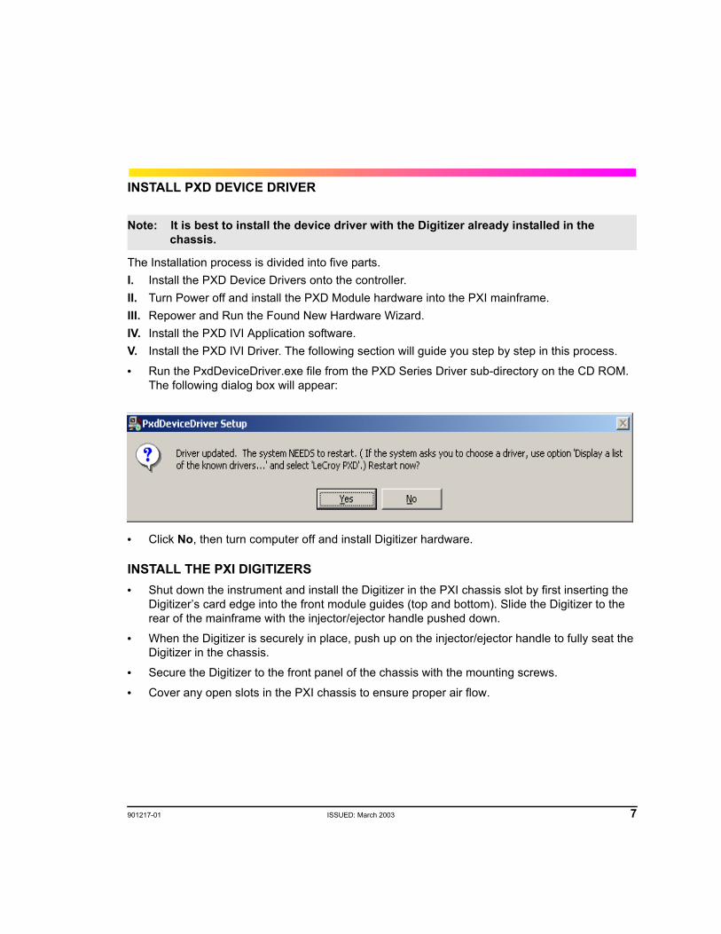
• Run the PxdDeviceDriver.exe file from the PXD Series Driver sub-directory on the CD ROM. The following dialog box will appear:
• Click No, then turn computer off and install Digitizer hardware.
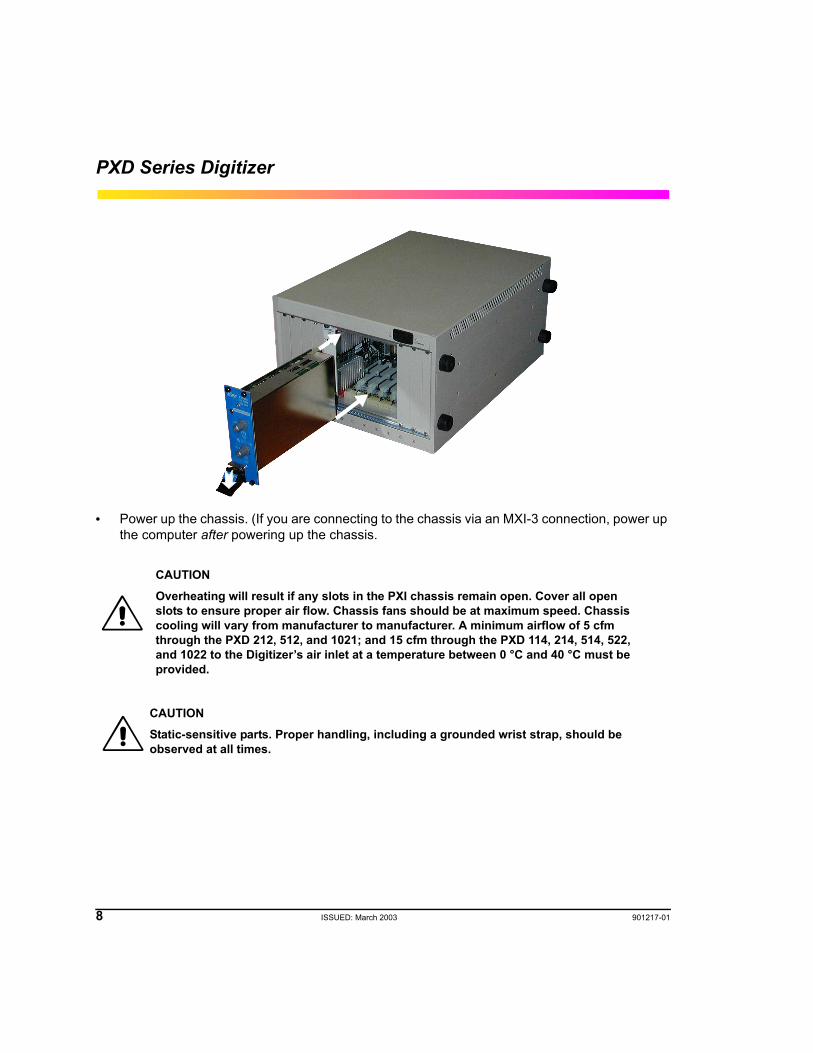
INSTALL THE PXI DIGITIZERS• Shut down the instrument and install the Digitizer in the PXI chassis slot by first inserting the
Digitizer’s card edge into the front module guides (top and bottom). Slide the Digitizer to the rear of the mainframe with the injector/ejector handle pushed down.
• When the Digitizer is securely in place, push up on the injector/ejector handle to fully seat the Digitizer in the chassis.
• Secure the Digitizer to the front panel of the chassis with the mounting screws.
• Cover any open slots in the PXI chassis to ensure proper air flow.
Note: It is best to install the device driver with the Digitizer already installed in the chassis.
8 ISSUED: March 2003 901217-01
PXD Series Digitizer
• Power up the chassis. (If you are connecting to the chassis via an MXI-3 connection, power up the computer after powering up the chassis.
CAUTIONOverheating will result if any slots in the PXI chassis remain open. Cover all open slots to ensure proper air flow. Chassis fans should be at maximum speed. Chassis cooling will vary from manufacturer to manufacturer. A minimum airflow of 5 cfm through the PXD 212, 512, and 1021; and 15 cfm through the PXD 114, 214, 514, 522, and 1022 to the Digitizer’s air inlet at a temperature between 0 °C and 40 °C must be provided.
CAUTIONStatic-sensitive parts. Proper handling, including a grounded wrist strap, should be observed at all times.
901217-01 ISSUED: March 2003 9
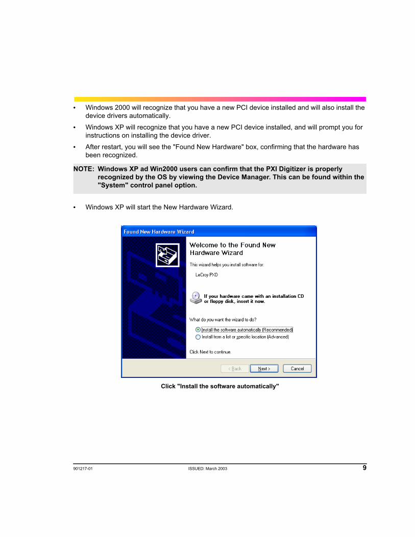
• Windows 2000 will recognize that you have a new PCI device installed and will also install the device drivers automatically.
• Windows XP will recognize that you have a new PCI device installed, and will prompt you for instructions on installing the device driver.
• After restart, you will see the "Found New Hardware" box, confirming that the hardware has been recognized.
• Windows XP will start the New Hardware Wizard.
Click "Install the software automatically"
NOTE: Windows XP ad Win2000 users can confirm that the PXI Digitizer is properly recognized by the OS by viewing the Device Manager. This can be found within the "System" control panel option.
10 ISSUED: March 2003 901217-01
PXD Series Digitizer
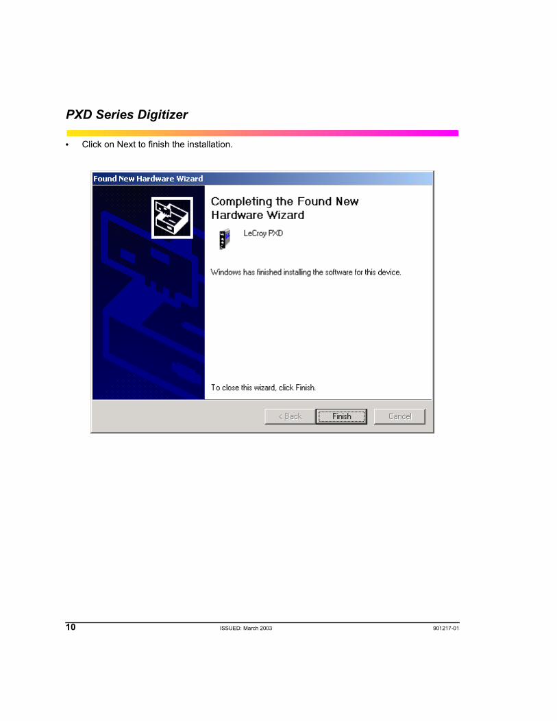
• Click on Next to finish the installation.
901217-01 ISSUED: March 2003 11
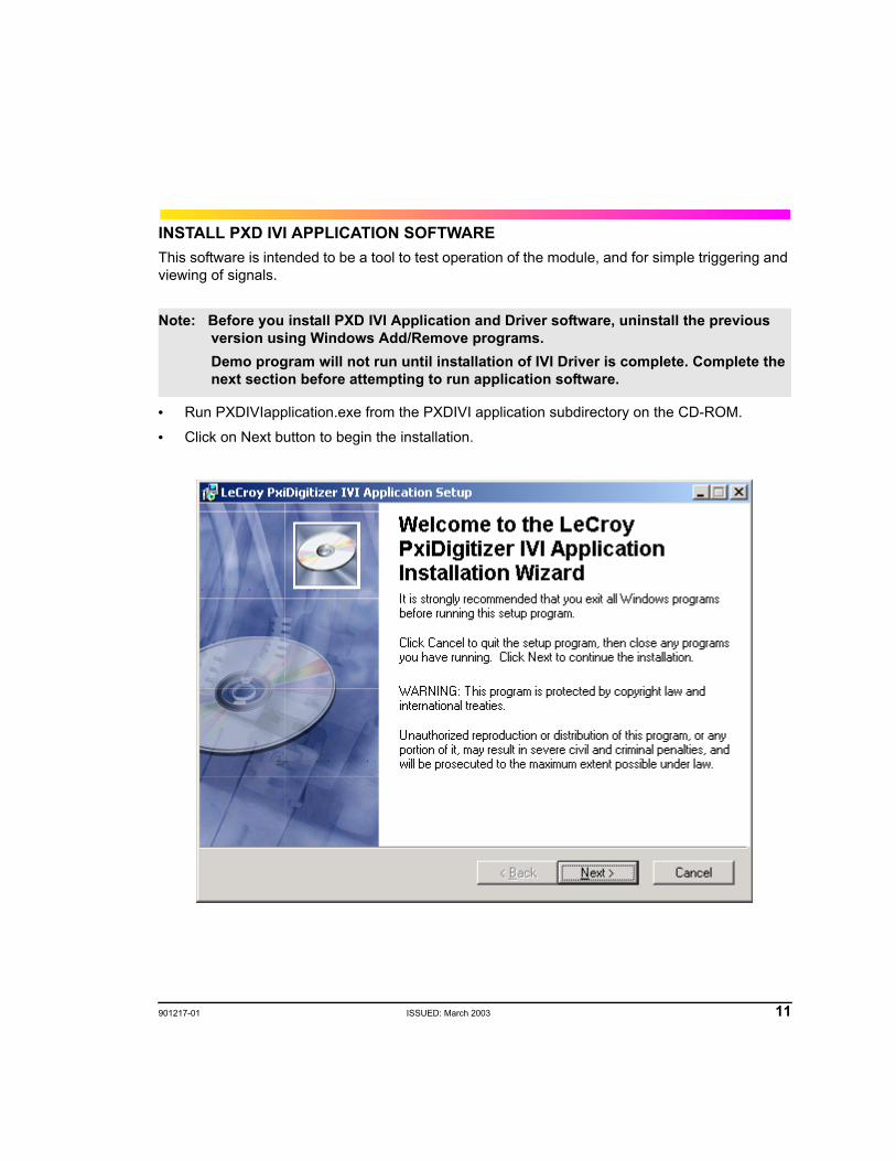
INSTALL PXD IVI APPLICATION SOFTWAREThis software is intended to be a tool to test operation of the module, and for simple triggering and viewing of signals.
• Run PXDIVIapplication.exe from the PXDIVI application subdirectory on the CD-ROM.
• Click on Next button to begin the installation.
Note: Before you install PXD IVI Application and Driver software, uninstall the previous version using Windows Add/Remove programs.Demo program will not run until installation of IVI Driver is complete. Complete the next section before attempting to run application software.
12 ISSUED: March 2003 901217-01
PXD Series Digitizer
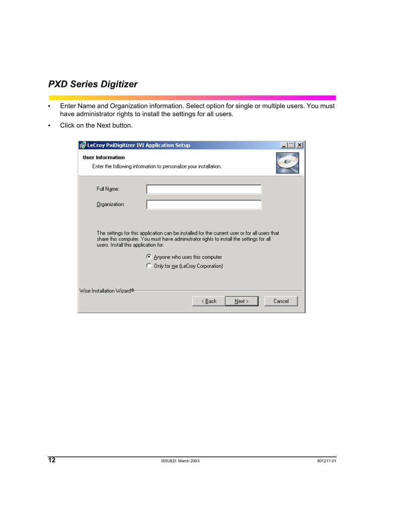
• Enter Name and Organization information. Select option for single or multiple users. You must have administrator rights to install the settings for all users.
• Click on the Next button.
901217-01 ISSUED: March 2003 13
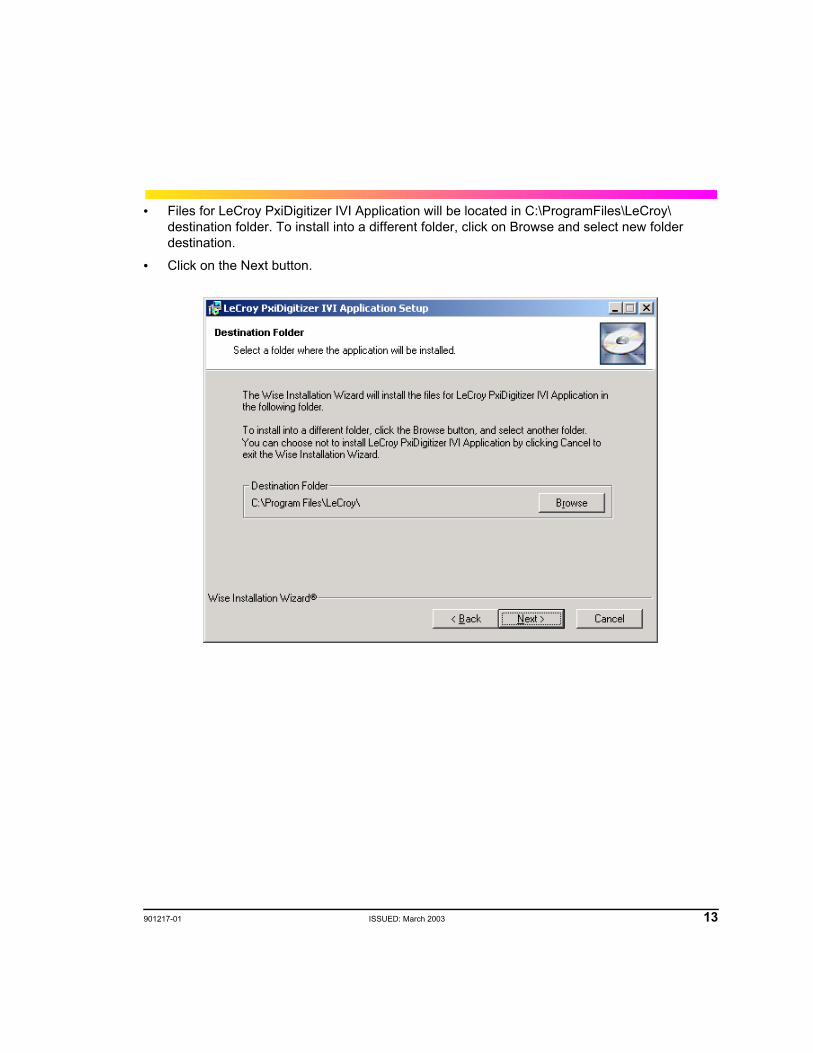
• Files for LeCroy PxiDigitizer IVI Application will be located in C:\ProgramFiles\LeCroy\ destination folder. To install into a different folder, click on Browse and select new folder destination.
• Click on the Next button.
14 ISSUED: March 2003 901217-01
PXD Series Digitizer
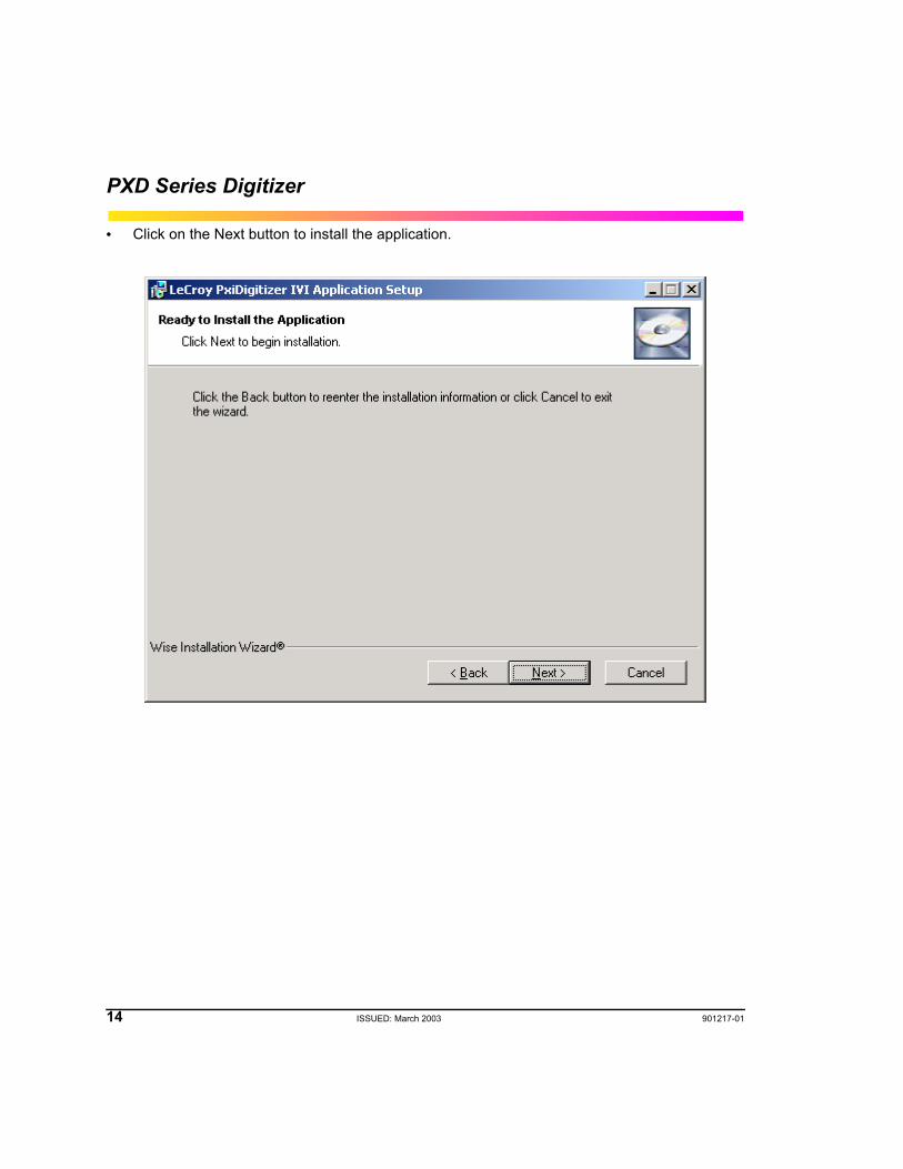
• Click on the Next button to install the application.
901217-01 ISSUED: March 2003 15
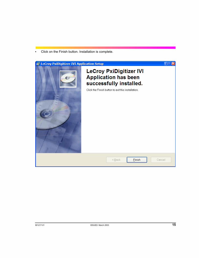
• Click on the Finish button. Installation is complete.
16 ISSUED: March 2003 901217-01
PXD Series Digitizer
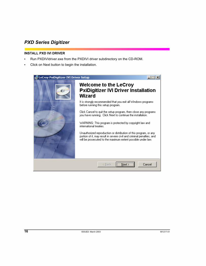
INSTALL PXD IVI DRIVER• Run PXDIVIdriver.exe from the PXDIVI driver subdirectory on the CD-ROM.
• Click on Next button to begin the installation.
901217-01 ISSUED: March 2003 17
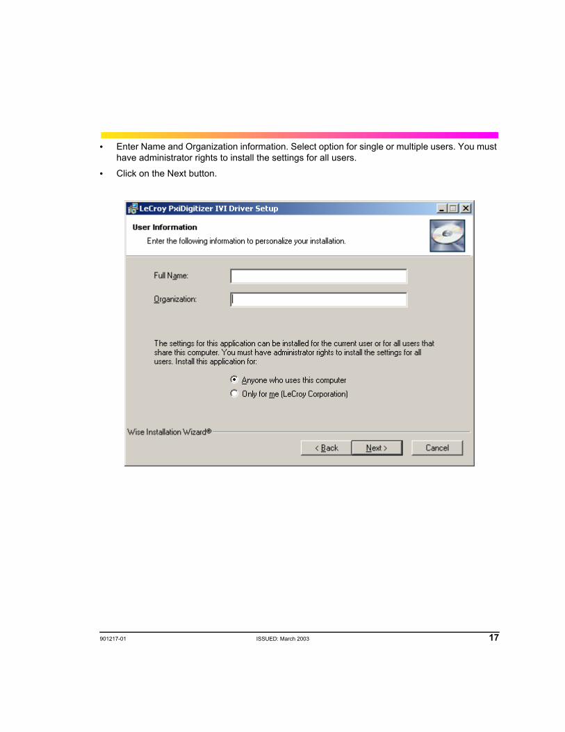
• Enter Name and Organization information. Select option for single or multiple users. You must have administrator rights to install the settings for all users.
• Click on the Next button.
18 ISSUED: March 2003 901217-01
PXD Series Digitizer
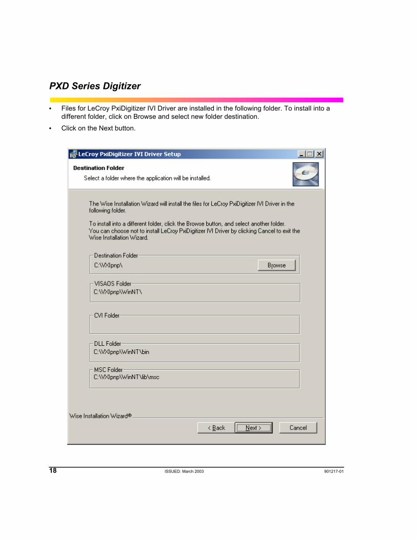
• Files for LeCroy PxiDigitizer IVI Driver are installed in the following folder. To install into a different folder, click on Browse and select new folder destination.
• Click on the Next button.
901217-01 ISSUED: March 2003 19
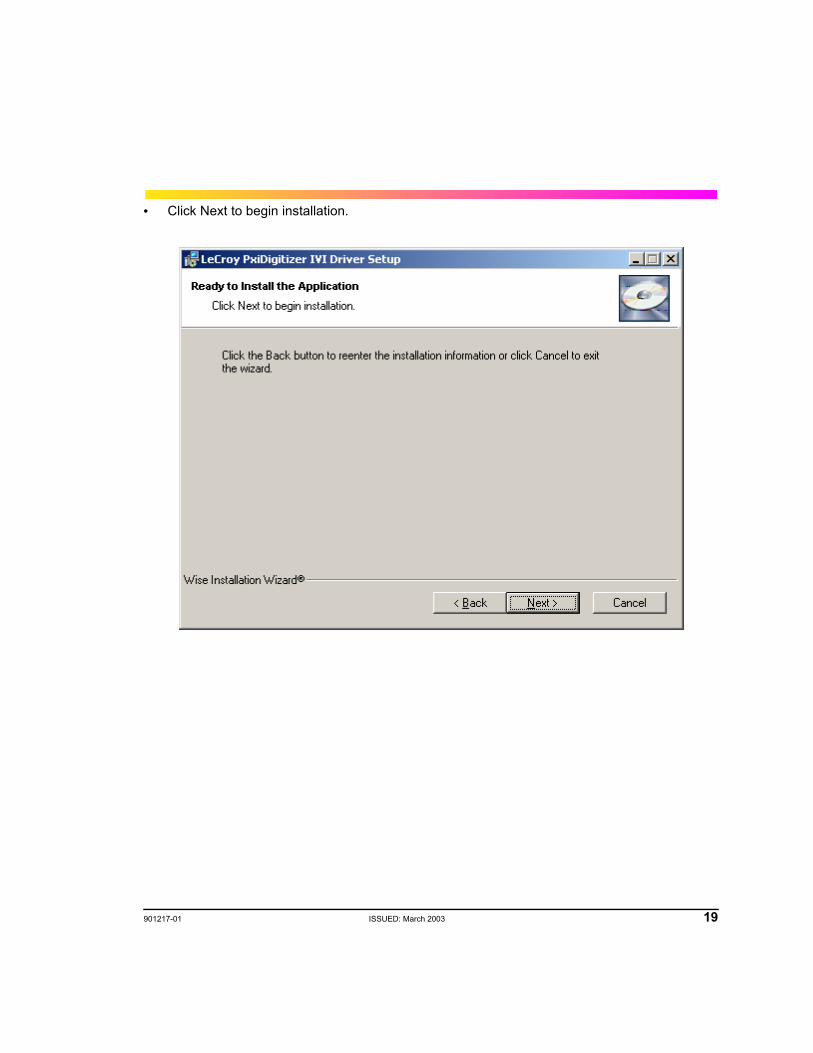
• Click Next to begin installation.
20 ISSUED: March 2003 901217-01
PXD Series Digitizer
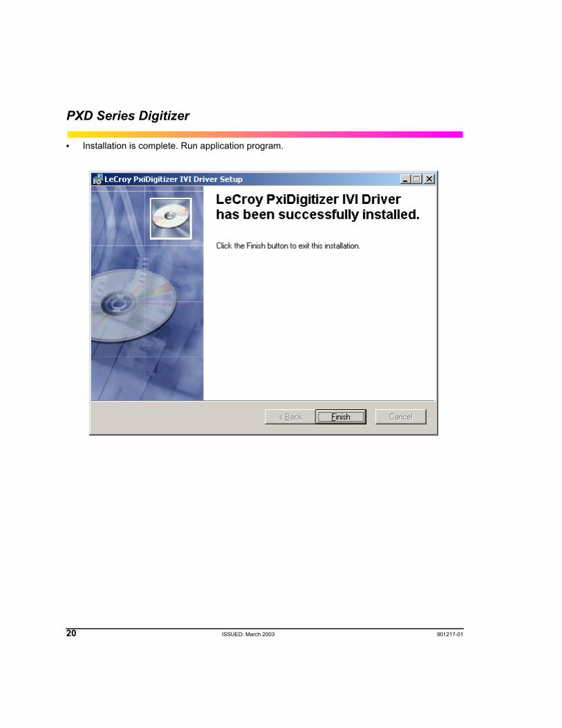
• Installation is complete. Run application program.
901217-01 ISSUED: March 2003 21
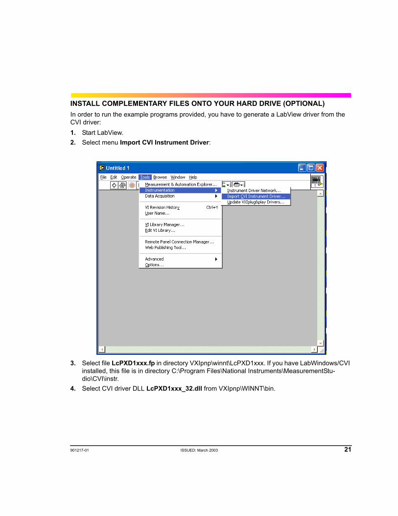
INSTALL COMPLEMENTARY FILES ONTO YOUR HARD DRIVE (OPTIONAL)In order to run the example programs provided, you have to generate a LabView driver from the CVI driver:1. Start LabView.2. Select menu Import CVI Instrument Driver:
3. Select file LcPXD1xxx.fp in directory VXIpnp\winnt\LcPXD1xxx. If you have LabWindows/CVI installed, this file is in directory C:\Program Files\National Instruments\MeasurementStu-dio\CVI\instr.
4. Select CVI driver DLL LcPXD1xxx_32.dll from VXIpnp\WINNT\bin.
22 ISSUED: March 2003 901217-01
PXD Series Digitizer
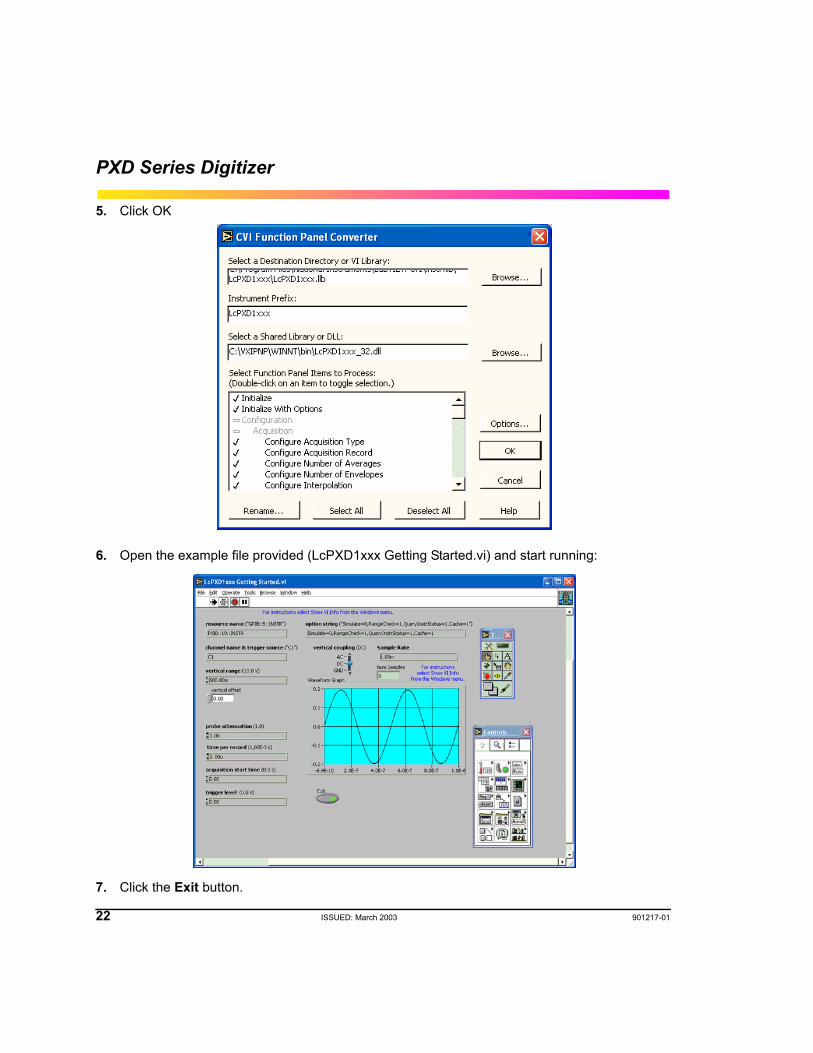
5. Click OK
6. Open the example file provided (LcPXD1xxx Getting Started.vi) and start running:
7. Click the Exit button.

901217-01 ISSUED: March 2003 23
8. Wait until execution is finished.9. Exit from LabView.
§ § §
24 ISSUED: March 2003 901217-01
PXD Series Digitizer
BLANK PAGE

Operation
901217-01 ISSUED: March 2003 25
INTRODUCTIONThis section provides information about the standard acquisition, triggering, and measurement features of the PXD Series Digitizer. LeCroy PXD digitizers are IVI compliant which means that the structure of commands for setting up, capturing, and reading out waveforms follows the structure defined in Section 4 of the IVI Foundation specification (www.IVIfoundation.org). It is recom-mended that you review this section prior to programming the PXD modules. Detailed descriptions of LeCroy commands are included in the Driver Help file.
ACQUISITION MODESThe Digitizer has three modes of operation: NORMAL, RIS (Random Interleaved Sampling), and Sequence. These are defined as follows:NormalIn Normal mode, the Digitizer will input the signals during a specified time window and create a data array with the digitized data, which can be read out by the controller. The user programs the number of points as well as the time window to be digitized on repetitive signals. LeCroy PXD Dig-itizers come with 256 kpoints of memory as standard. For storing longer single-shot signals, opti-mal memory of 4 Mpoints or 8 Mpoints/channel can be added. The maximum sample rate is 2 GS/s, and will vary depending on the specific model and the time window setting.RIS – For Higher Sample RatesRIS (Random Interleaved Sampling) is an acquisition technique that allows effective sampling rates higher than the maximum single-shot sampling rate. It is used on repetitive waveforms with a stable trigger. The maximum effective Digitizer sampling rate of 50 GS/s can be achieved with RIS by making 100 single-shot acquisitions at 500 MS/s. The bins thus acquired are positioned approximately 20 ps apart. The process of acquiring these bins and satisfying the time constraint is a random one. The relative time between ADC sampling instants and the event trigger provides the necessary variation, measured by the timebase to 5 ps resolution.The Digitizer requires multiple triggers to complete an acquisition. The number depends on the sample rate: the higher the sample rate, the more triggers are required. It then interleaves these segments to provide a waveform that is up to 50x faster than the single-shot sampling rate. How-ever, the real-time interval over which the Digitizer collects the waveform data is much longer, and depends on the trigger rate and the amount of interleaving required. The digitizer is capable of acquiring approximately 40,000 RIS acquisitions per second.
26 ISSUED: March 2003 901217-01
PXD Series Digitizer
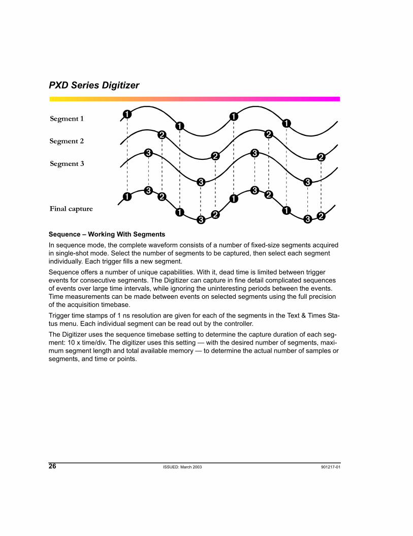
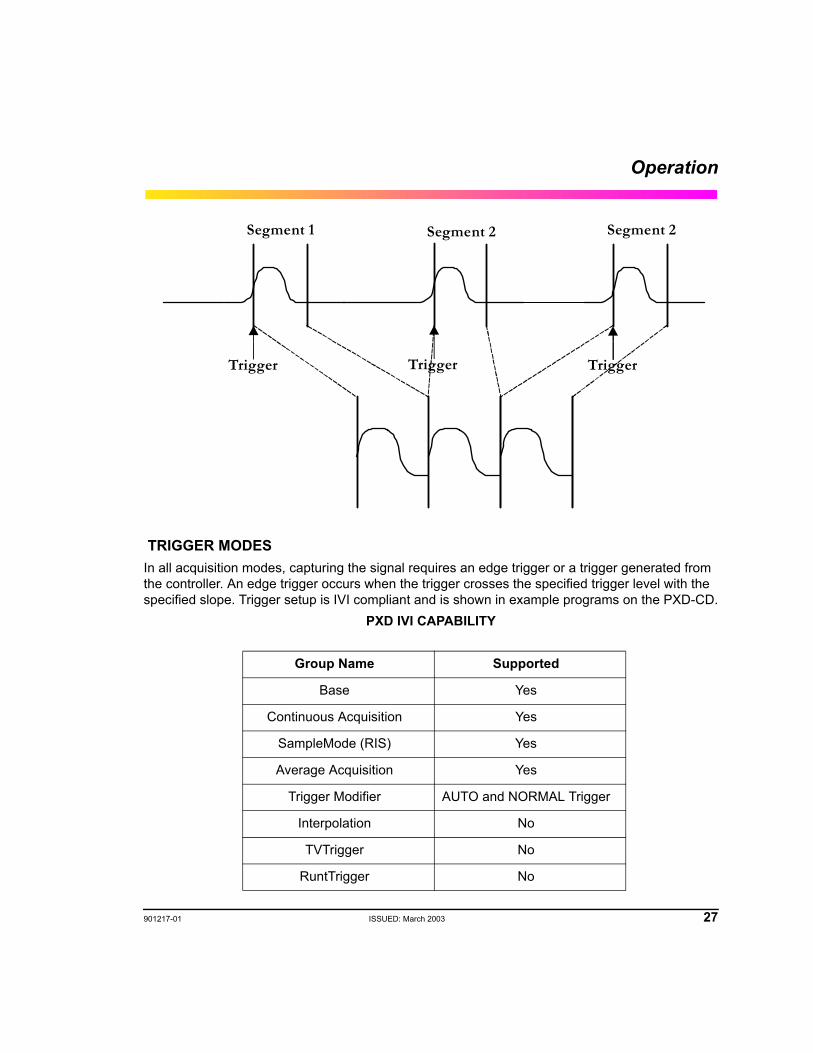
Sequence – Working With SegmentsIn sequence mode, the complete waveform consists of a number of fixed-size segments acquired in single-shot mode. Select the number of segments to be captured, then select each segment individually. Each trigger fills a new segment.Sequence offers a number of unique capabilities. With it, dead time is limited between trigger events for consecutive segments. The Digitizer can capture in fine detail complicated sequences of events over large time intervals, while ignoring the uninteresting periods between the events. Time measurements can be made between events on selected segments using the full precision of the acquisition timebase.Trigger time stamps of 1 ns resolution are given for each of the segments in the Text & Times Sta-tus menu. Each individual segment can be read out by the controller.The Digitizer uses the sequence timebase setting to determine the capture duration of each seg-ment: 10 x time/div. The digitizer uses this setting — with the desired number of segments, maxi-mum segment length and total available memory — to determine the actual number of samples or segments, and time or points.
Segment 1
Segment 3
Segment 2
Final capture
Operation
901217-01 ISSUED: March 2003 27
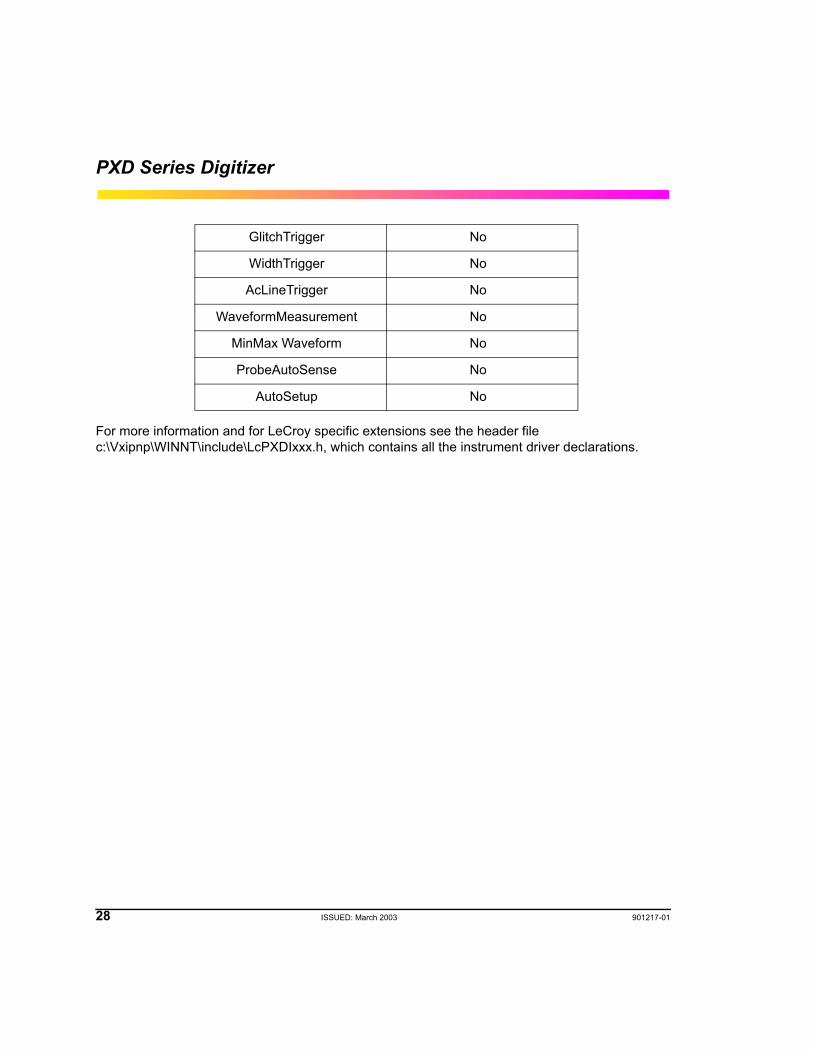
TRIGGER MODESIn all acquisition modes, capturing the signal requires an edge trigger or a trigger generated from the controller. An edge trigger occurs when the trigger crosses the specified trigger level with the specified slope. Trigger setup is IVI compliant and is shown in example programs on the PXD-CD.
PXD IVI CAPABILITY
Group Name Supported
Base Yes
Continuous Acquisition Yes
SampleMode (RIS) Yes
Average Acquisition Yes
Trigger Modifier AUTO and NORMAL Trigger
Interpolation No
TVTrigger No
RuntTrigger No
Segment 1 Segment 2 Segment 2
Trigger Trigger Trigger
28 ISSUED: March 2003 901217-01
PXD Series Digitizer
For more information and for LeCroy specific extensions see the header file c:\Vxipnp\WINNT\include\LcPXDIxxx.h, which contains all the instrument driver declarations.
GlitchTrigger No
WidthTrigger No
AcLineTrigger No
WaveformMeasurement No
MinMax Waveform No
ProbeAutoSense No
AutoSetup No
Operation
901217-01 ISSUED: March 2003 29
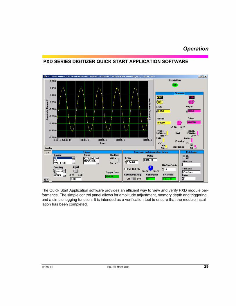
PXD SERIES DIGITIZER QUICK START APPLICATION SOFTWARE
The Quick Start Application software provides an efficient way to view and verify PXD module per-formance. The simple control panel allows for amplitude adjustment, memory depth and triggering, and a simple logging function. It is intended as a verification tool to ensure that the module instal-lation has been completed.
30 ISSUED: March 2003 901217-01
PXD Series Digitizer
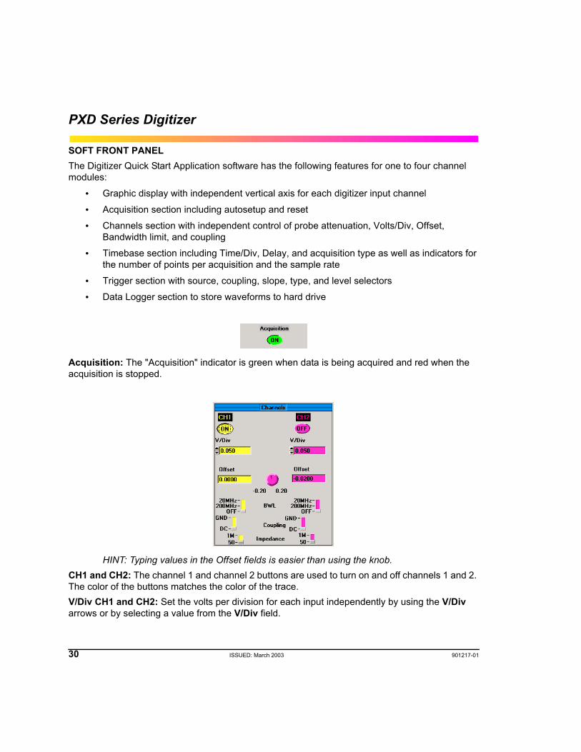
SOFT FRONT PANELThe Digitizer Quick Start Application software has the following features for one to four channel modules:
• Graphic display with independent vertical axis for each digitizer input channel
• Acquisition section including autosetup and reset
• Channels section with independent control of probe attenuation, Volts/Div, Offset, Bandwidth limit, and coupling
• Timebase section including Time/Div, Delay, and acquisition type as well as indicators for the number of points per acquisition and the sample rate
• Trigger section with source, coupling, slope, type, and level selectors
• Data Logger section to store waveforms to hard drive
Acquisition: The "Acquisition" indicator is green when data is being acquired and red when the acquisition is stopped.
HINT: Typing values in the Offset fields is easier than using the knob.CH1 and CH2: The channel 1 and channel 2 buttons are used to turn on and off channels 1 and 2. The color of the buttons matches the color of the trace.V/Div CH1 and CH2: Set the volts per division for each input independently by using the V/Div arrows or by selecting a value from the V/Div field.
Operation
901217-01 ISSUED: March 2003 31
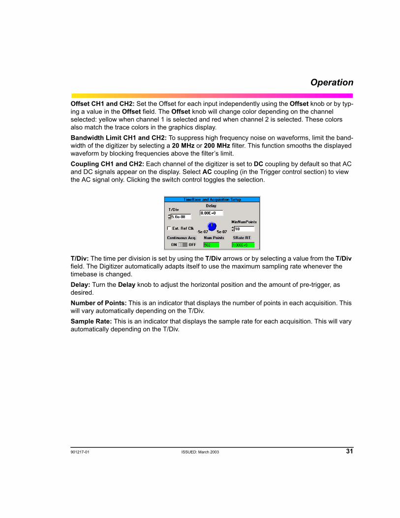
Offset CH1 and CH2: Set the Offset for each input independently using the Offset knob or by typ-ing a value in the Offset field. The Offset knob will change color depending on the channel selected: yellow when channel 1 is selected and red when channel 2 is selected. These colors also match the trace colors in the graphics display.Bandwidth Limit CH1 and CH2: To suppress high frequency noise on waveforms, limit the band-width of the digitizer by selecting a 20 MHz or 200 MHz filter. This function smooths the displayed waveform by blocking frequencies above the filter’s limit.Coupling CH1 and CH2: Each channel of the digitizer is set to DC coupling by default so that AC and DC signals appear on the display. Select AC coupling (in the Trigger control section) to view the AC signal only. Clicking the switch control toggles the selection.
T/Div: The time per division is set by using the T/Div arrows or by selecting a value from the T/Div field. The Digitizer automatically adapts itself to use the maximum sampling rate whenever the timebase is changed.Delay: Turn the Delay knob to adjust the horizontal position and the amount of pre-trigger, as desired.Number of Points: This is an indicator that displays the number of points in each acquisition. This will vary automatically depending on the T/Div.Sample Rate: This is an indicator that displays the sample rate for each acquisition. This will vary automatically depending on the T/Div.
32 ISSUED: March 2003 901217-01
PXD Series Digitizer
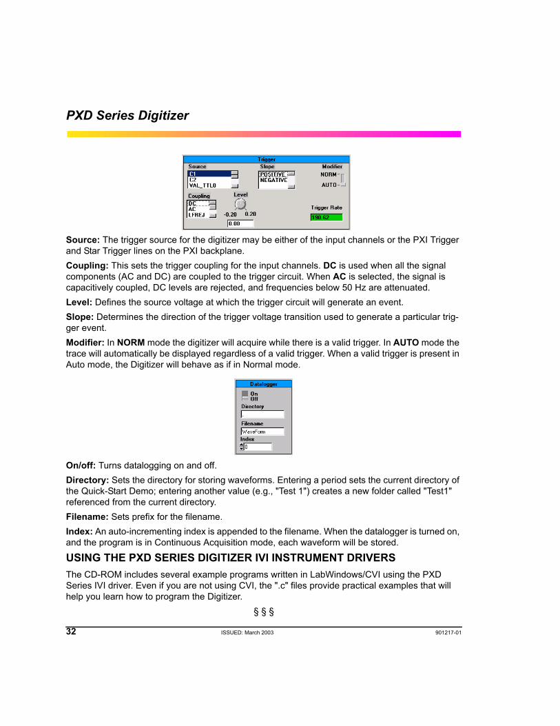
Source: The trigger source for the digitizer may be either of the input channels or the PXI Trigger and Star Trigger lines on the PXI backplane.Coupling: This sets the trigger coupling for the input channels. DC is used when all the signal components (AC and DC) are coupled to the trigger circuit. When AC is selected, the signal is capacitively coupled, DC levels are rejected, and frequencies below 50 Hz are attenuated.Level: Defines the source voltage at which the trigger circuit will generate an event.Slope: Determines the direction of the trigger voltage transition used to generate a particular trig-ger event.Modifier: In NORM mode the digitizer will acquire while there is a valid trigger. In AUTO mode the trace will automatically be displayed regardless of a valid trigger. When a valid trigger is present in Auto mode, the Digitizer will behave as if in Normal mode.
On/off: Turns datalogging on and off.Directory: Sets the directory for storing waveforms. Entering a period sets the current directory of the Quick-Start Demo; entering another value (e.g., "Test 1") creates a new folder called "Test1" referenced from the current directory.Filename: Sets prefix for the filename.Index: An auto-incrementing index is appended to the filename. When the datalogger is turned on, and the program is in Continuous Acquisition mode, each waveform will be stored.
USING THE PXD SERIES DIGITIZER IVI INSTRUMENT DRIVERSThe CD-ROM includes several example programs written in LabWindows/CVI using the PXD Series IVI driver. Even if you are not using CVI, the ".c" files provide practical examples that will help you learn how to program the Digitizer.
§ § §
901217-01 ISSUED: March 2003 33
PXD SERIES DIGITIZER SPECIFICATIONS
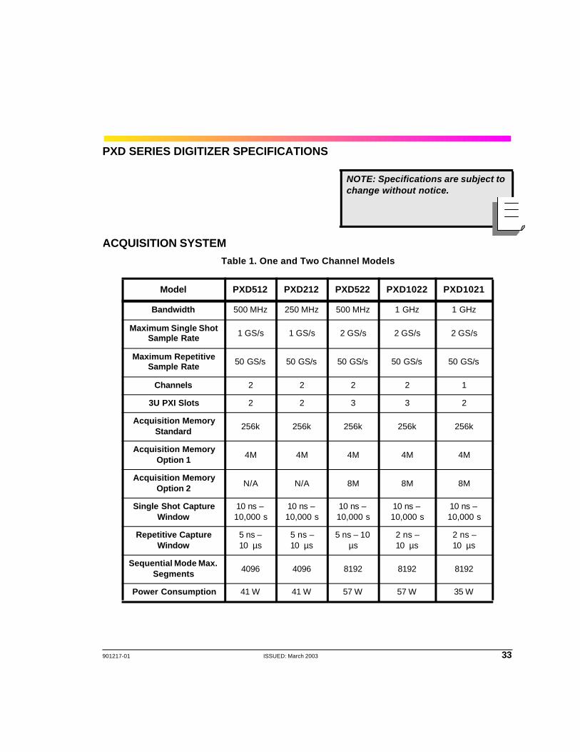
ACQUISITION SYSTEMTable 1. One and Two Channel Models
NOTE: Specifications are subject to change without notice.
Model PXD512 PXD212 PXD522 PXD1022 PXD1021
Bandwidth 500 MHz 250 MHz 500 MHz 1 GHz 1 GHz
Maximum Single Shot Sample Rate 1 GS/s 1 GS/s 2 GS/s 2 GS/s 2 GS/s
Maximum Repetitive Sample Rate 50 GS/s 50 GS/s 50 GS/s 50 GS/s 50 GS/s
Channels 2 2 2 2 1
3U PXI Slots 2 2 3 3 2
Acquisition Memory Standard 256k 256k 256k 256k 256k
Acquisition Memory Option 1 4M 4M 4M 4M 4M
Acquisition Memory Option 2 N/A N/A 8M 8M 8M
Single Shot Capture Window
10 ns – 10,000 s
10 ns – 10,000 s
10 ns – 10,000 s
10 ns – 10,000 s
10 ns – 10,000 s
Repetitive Capture Window
5 ns –10 µs
5 ns – 10 µs
5 ns – 10 µs
2 ns – 10 µs
2 ns – 10 µs
Sequential Mode Max. Segments 4096 4096 8192 8192 8192
Power Consumption 41 W 41 W 57 W 57 W 35 W
34 ISSUED: March 2003 901217-01
PXD Series Digitizer
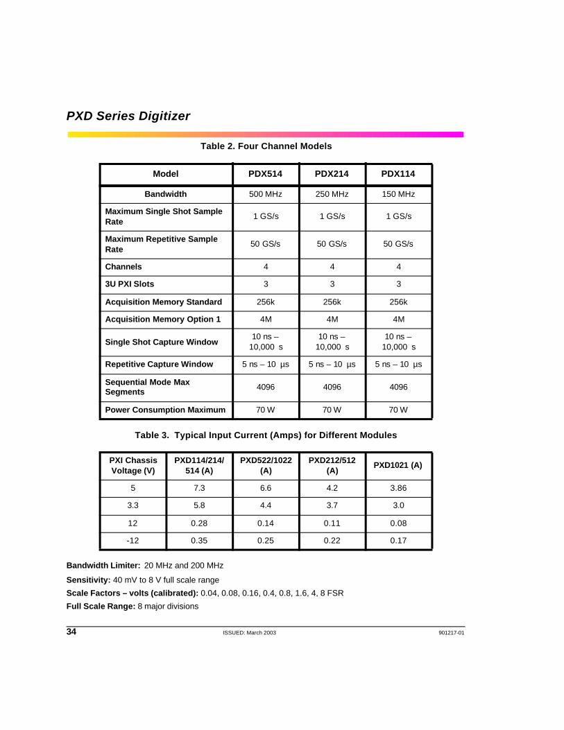
Table 2. Four Channel Models
Table 3. Typical Input Current (Amps) for Different Modules
Bandwidth Limiter: 20 MHz and 200 MHz
Sensitivity: 40 mV to 8 V full scale range
Scale Factors – volts (calibrated): 0.04, 0.08, 0.16, 0.4, 0.8, 1.6, 4, 8 FSR
Full Scale Range: 8 major divisions
Model PDX514 PDX214 PDX114
Bandwidth 500 MHz 250 MHz 150 MHz
Maximum Single Shot Sample Rate
1 GS/s 1 GS/s 1 GS/s
Maximum Repetitive Sample Rate
50 GS/s 50 GS/s 50 GS/s
Channels 4 4 4
3U PXI Slots 3 3 3
Acquisition Memory Standard 256k 256k 256k
Acquisition Memory Option 1 4M 4M 4M
Single Shot Capture Window10 ns –
10,000 s10 ns –
10,000 s10 ns –
10,000 s
Repetitive Capture Window 5 ns – 10 µs 5 ns – 10 µs 5 ns – 10 µs
Sequential Mode Max Segments 4096 4096 4096
Power Consumption Maximum 70 W 70 W 70 W
PXI Chassis Voltage (V)
PXD114/214/514 (A)
PXD522/1022 (A)
PXD212/512 (A)
PXD1021 (A)
5 7.3 6.6 4.2 3.86
3.3 5.8 4.4 3.7 3.0
12 0.28 0.14 0.11 0.08
-12 0.35 0.25 0.22 0.17
901217-01 ISSUED: March 2003 35
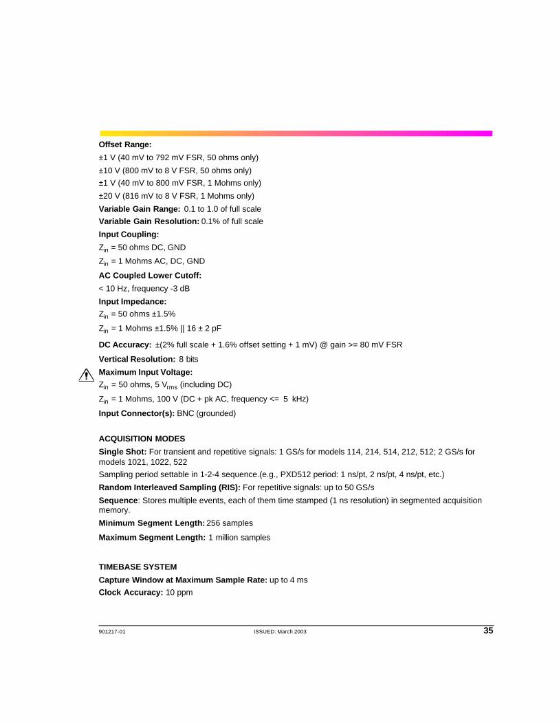
Offset Range:
±1 V (40 mV to 792 mV FSR, 50 ohms only)
±10 V (800 mV to 8 V FSR, 50 ohms only)±1 V (40 mV to 800 mV FSR, 1 Mohms only)
±20 V (816 mV to 8 V FSR, 1 Mohms only)
Variable Gain Range: 0.1 to 1.0 of full scaleVariable Gain Resolution: 0.1% of full scale
Input Coupling:
Zin = 50 ohms DC, GND
Zin = 1 Mohms AC, DC, GND
AC Coupled Lower Cutoff:
< 10 Hz, frequency -3 dB
Input Impedance:Zin = 50 ohms ±1.5%
Zin = 1 Mohms ±1.5% || 16 ± 2 pF
DC Accuracy: ±(2% full scale + 1.6% offset setting + 1 mV) @ gain >= 80 mV FSR
Vertical Resolution: 8 bits
Maximum Input Voltage: Zin = 50 ohms, 5 Vrms (including DC)
Zin = 1 Mohms, 100 V (DC + pk AC, frequency <= 5 kHz)
Input Connector(s): BNC (grounded)
ACQUISITION MODES
Single Shot: For transient and repetitive signals: 1 GS/s for models 114, 214, 514, 212, 512; 2 GS/s for models 1021, 1022, 522Sampling period settable in 1-2-4 sequence.(e.g., PXD512 period: 1 ns/pt, 2 ns/pt, 4 ns/pt, etc.)
Random Interleaved Sampling (RIS): For repetitive signals: up to 50 GS/s
Sequence: Stores multiple events, each of them time stamped (1 ns resolution) in segmented acquisition memory.
Minimum Segment Length: 256 samples
Maximum Segment Length: 1 million samples
TIMEBASE SYSTEM
Capture Window at Maximum Sample Rate: up to 4 msClock Accuracy: 10 ppm
36 ISSUED: March 2003 901217-01
PXD Series Digitizer
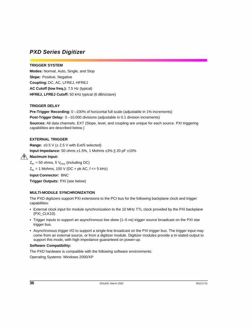
TRIGGER SYSTEM
Modes: Normal, Auto, Single, and Stop
Slope: Positive, Negative Coupling: DC, AC, LFREJ, HFREJ
AC Cutoff (low freq.): 7.5 Hz (typical)
HFREJ, LFREJ Cutoff: 50 kHz typical (6 dB/octave)
TRIGGER DELAY
Pre-Trigger Recording: 0 –100% of horizontal full scale (adjustable in 1% increments)Post-Trigger Delay: 0 –10,000 divisions (adjustable in 0.1 division increments)
Sources: All data channels, EXT (Slope, level, and coupling are unique for each source. PXI triggering capabilities are described below.)
EXTERNAL TRIGGER
Range: ±0.5 V (± 2.5 V with Ext/5 selected)Input Impedance: 50 ohms ±1.5%, 1 Mohms ±3% || 20 pF ±10%
Maximum Input:
Zin = 50 ohms, 5 Vrms (including DC)
Zin = 1 Mohms, 100 V (DC + pk AC, f <= 5 kHz)
Input Connector: BNC
Trigger Outputs: PXI (see below)
MULTI-MODULE SYNCHRONIZATION
The PXD digitizers support PXI extensions to the PCI bus for the following backplane clock and trigger capabilities:
• External clock input for module synchronization to the 10 MHz TTL clock provided by the PXI backplane (PXI_CLK10).
• Trigger inputs to support an asynchronous low skew (1–5 ns) trigger source broadcast on the PXI star trigger bus.
• Asynchronous trigger I/O to support a single-line broadcast on the PXI trigger bus. The trigger input may come from an external source, or from a digitizer module. Digitizer modules provide a tri-stated output to support this mode, with high impedance guaranteed on power-up.
Software Compatibility:
The PXD hardware is compatible with the following software environments:Operating Systems: Windows 2000/XP

901217-01 ISSUED: March 2003 37
Supported Drivers:
• IVI-Scope Driver
• LeCroy PXD Getting Started Application Program
• ActiveX Control
• LabView DriverUPDATE RATESupports PCI Bus transfer rates up to 100 MB/s peak data rates.
GENERALAuto-Calibration: Ensures specified DC and timing accuracy.
Auto-Calibration Time: < 500 ms
Recommended Factory Calibration Interval: one yearTemperature
Operating: 0 to 40 °C when installed in a PXI chassis with a minimum airflow of 5 cfm (PXD 212, 512, 1021) or 15 cfm (PXD 114, 214, 514, 522, 1022) provided to the air inlet of the DigitizerStorage (Non-Op): -40 to +71°C
HumidityOperating: 5 to 80% RH (non-condensing). Upper limit derates to 50% RH above 30 °C.
Storage (Non-op): 5 to 95% RH (non-condensing). Upper limit derates to 75% RH above 30 °C and 45% RH above 40 °C.
Altitude
Operating: Up to 3,048 m (10,000 ft) at or below 25 °C Storage (Non-op): Up to 12,192 m (40,000 ft)
VibrationOperating: Random vibration, 0.31 grms, 5 to 500 Hz, 15 minutes in each of 3 orthogonal axes
Non-operating: Random vibration, 2.4 grms, 5 to 500 Hz, 15 minutes in each of 3 orthogonal axes
Functional Shock: 30 gpeak, half sine, 11 ms, 3 shocks (positive and negative) in each of 3 orthogonal axes, 18 shocks total
Electromagnetic Compatibility: Conforms to EN 61326-1:1998 (Emissions and Immunity)
Safety: Conforms to EN 61010-1:2001 (Installation Category I, Pollution Degree 2)
Certifications: CE Approved
38 ISSUED: March 2003 901217-01
PXD Series Digitizer
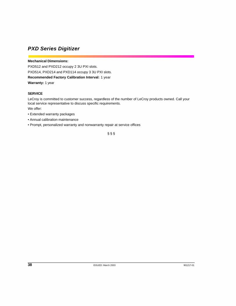
Mechanical Dimensions:
PXD512 and PXD212 occupy 2 3U PXI slots.
PXD514, PXD214 and PXD114 occupy 3 3U PXI slots.Recommended Factory Calibration Interval: 1 year
Warranty: 1 year
SERVICE
LeCroy is committed to customer success, regardless of the number of LeCroy products owned. Call your local service representative to discuss specific requirements. We offer:
• Extended warranty packages
• Annual calibration maintenance• Prompt, personalized warranty and nonwarranty repair at service offices
§ § §