Embed Size (px)
Citation preview

PWVAPI 610
Vertical Turbine PumpVS6 (Can Type)VS1 (Sump Type)

8885 Monroe Rd, Houston, TX 77061 USA
Phone: 713-9562002 Fax: 713-9562141
www.pumpworks610.com
Page 1 of 21
REV 1
INSTRUCTION MANUAL FOR INSTALLATION,
OPERATION, MAINTENANCE AND SPARE PARTS API 610 VERTICAL TRUBINE PUMP
VS6 (CAN TYPE) VS1 (SUMP TYPE)

8885 Monroe Rd, Houston, TX 77061 USA
Phone: 713-9562002 Fax: 713-9562141
www.pumpworks610.com
Page 2 of 21
REV 1
TABLE OF CONTENTS
Section 1 Introduction Page 3
Section 2 Storage Page 4
Section 3 General Description Page 5
Section 4 Barrel Installation Page 6
Section 5 Assembled Pump Installation Page 7
Section 6 Installing the Bowl Assembly Page 7
Section 7 Installing the Column Page 8
Section 8 Installing the Discharge Head Page 9
Section 9 Installing the Driver Stand Page 9
Section 10 Mechanical Seal Installation Page 9
Section 11 Installing the Driver Page 10
Section 12 Pump Start-Up and Operation Page 10
Section 13 Maintenance Page 13
Section 14 Troubleshooting Page 13
Section 15 Pump Disassembly & Reassembly Page 14
Annex A Cross Sections Page 18
Annex B Running-Installed clearances Page 21

8885 Monroe Rd, Houston, TX 77061 USA
Phone: 713-9562002 Fax: 713-9562141
www.pumpworks610.com
Page 3 of 21
REV 1
SECTION 1 – INTRODUCTION
The design, material, and workmanship incorporated in the construction of PW610 Pumps
makes them capable of giving long, trouble-free service. The life and satisfactory service of any
mechanical unit, however, is enhanced and extended by correct application, proper installation,
periodic inspection and careful maintenance.
This instruction manual was prepared to assist operators in understanding the construction and
the correct methods of installing, operating and maintaining these pumps. It is advisable that
rotating components of the pump assembly be covered with a suitable rigid guard to prevent
injury to personnel.
Study thoroughly Sections 1 thru 11 and carefully follow the instructions for installing and
operating. Sections 12 thru 14 are answers to trouble and maintenance questions. Keep this
instruction manual readily available for reference.
RECEIVING AND CHECKING
The pump shall be carefully supported prior unloading from the carrier. Handle all components
carefully. Inspection for damage of the shipping crate shall be made prior to unpacking the
pump. After unpacking, visually inspect the pump and check the following:
1. Contents of the pump assembly against shipping list.
2. All components against damage.
3. Shafting for straightness and damage.
Any shortages or damages should be immediately called to the attention of the local freight
agent of the carrier by which the shipment arrived and proper notation made on the bill. This
shall prevent any controversy when a claim is made and facilitate prompt and satisfactory
adjustment.
MATERIALS AND EQUIPMENT REQUIRED
The material and equipment necessary for installation of the pump will vary with the size of the
pump and the type of installation.
The following list of standard tools and supplies is offered only as a guide:
1. BULK MATERIAL: Anti-Galling Lubricant, Thread Compound, Lubrication Oil, Turbine
Oil, Grease, and solvent (petroleum-base, kerosene, distillate or unleaded gasoline)
2. RIGGING EQUIPMENT: Mobile power hoist, dragline and blocks, elevator clamps,
Clevises-for use with eyebolts, timbers (size, length and quantity as required to
support long pump parts on the floor), and I-Beams or timbers to support pump
over barrel.
3. HAND TOOLS: Pipe wrenches, clean rags, feeler gages, and set of mechanic's tools
(including: files, wire brush, pliers, wire cutters, pocket knife, and pipe wrenches).

8885 Monroe Rd, Houston, TX 77061 USA
Phone: 713-9562002 Fax: 713-9562141
www.pumpworks610.com
Page 4 of 21
REV 1
4. OPTIONAL TOOLS TO FACILITATE PUMP ASSEMBLY AND DISASSEMBLY: Dial indicator
(to assist in motor end shaft adjustment) and Collet driver (to assist in bowl
assembly and disassembly when required).
SECTION 2 – STORAGE
STORAGE
PW610 carefully preserves and protects its products for shipment. However, the effective life of
the preservatives applied at the factory can vary 3 to 18 months depending on the severity of
the environment where the equipment is stored. This section provides procedures for
preparation prior to storage and maintenance during storage of PW610 Pumps. These
procedures are necessary to protect the precision parts of the pumps. Specific procedures for
storing motors, gear-heads and engines, should be obtained from the equipment manufacturer.
This section is intended to be of general assistance to users of PW610 Pumps. It shall not modify,
amend and/or otherwise alter the scope of PW610 Pumps warranty responsibilities to the purchaser
in any way whatsoever.
STORAGE PREPARATION
PW610 vertical pumps require proper preparation for storage and regular maintenance during
storage. The pump shall be considered in storage when it has been delivered to the job site and is
waiting installation.
RECOMMENDED STORAGEPROCEDURES
Controlled storage facilities should be maintained at an even temperature 10°F or more above the
dew point with relative humidity less than 50% and little or no dust. If these requirements cannot be
met the pump is to be considered in uncontrolled storage. For uncontrolled storage periods of 6
months or less, the pump is to be inspected periodically to insure that all preservatives are intact.
All pipe threads and flanged pipe covers are to be sealed with tape, plastic covers or blind flanges
and gaskets if available. The pump must not be stored closer than 6 inches from the ground.
PREPARATIONS FOR UNCONTROLLED LONG TERM STORAGE
When applicable to the pump, storage periods over 6 months require the preceding uncontrolled
storage procedure plus the following:
1. Inspect the lube oil and seal flush piping, and either fill the piping with rust preventative
oil, or recoat the piping periodically to prevent corrosion.
2. Place 10 pounds of moisture absorbing desiccant or 5 pounds of vapor phase inhibitor
crystals near the center of the pump. If the pump is assembled, place an additional one
pound in the discharge nozzle securely fastened to the discharge elbow.
3. Install a moisture indicator near the perimeter of the pump. Cover the pump with 6 mil
minimum thickness black polyethylene or equal and seal it with tape. Provide a small
ventilation hole approximately 1/2 inch diameter.

8885 Monroe Rd, Houston, TX 77061 USA
Phone: 713-9562002 Fax: 713-9562141
www.pumpworks610.com
Page 5 of 21
REV 1
4. Provide a roof or a shed shelter to protect from direct exposure to the elements.
SECTION 3 – GENERAL DESCRIPTION
GENERAL DESCRIPTION
The model PWV pumps are either vertically suspended can pump (VS6) or vertical suspended
sump/wet pit type pumps (VS1) designed to meet wide ranges of process injection and transfer
requirements in the petroleum and petrochemical industries. The PWV pumps also feature capacities
to 7000 GPM, heads to 3500 feet and pressures to 3000 PSIG. Special applications are also available
to meet cryogenics, high temperature or corrosive applications. See Annex A for Cross Sections.
DRIVERS
The most common type drivers supplied are solid shaft electric motors with rigid adjustable type
couplings that permit removal of the complete mechanical seal without removing the driver.
Occasionally right angle gear drives with solid shafts are also provided.
DISCHARGE HEAD
The discharge head may be a fabricated "T" type or "F" type head depending on design
requirements. Ports are provided for connecting suction gage, discharge gage. Flanges are provided
for stuffing box or mechanical seal bypass return and barrel vent piping. The discharge head is
designed with large hand holes for easy mechanical seal or stuffing box adjustment. All discharge
heads are designed and fabricated under ASME section VIII and hydro-tested to 1.5MAWP.
COLUMN
Flanged column construction provides positive shaft and bearing alignment, ease of assembly and
disassembly. Bearings are spaced to provide vibration free operation below shaft first critical speed
to insure long bearing life and reduced shaft wear. The line shaft is supported within the column by
use of integral bearing retainers in the column assembly. Each column flange connection is sealed an
O-ring or gasket depending on temperature and pressure requirements.
BOWL ASSEMBLY
The bowls are generally flanged construction for accurate alignment and ease of assembly and
disassembly. Impellers are enclosed for API compliance; however, open impeller are available
depending on design requirements. Impellers are keyed to the shaft. A special first stage low NPSH
impeller may be provided in certain applications. Each bowl flange connection is sealed an O-ring or
gasket depending on temperature and pressure requirements.
THRUST POT
A thrust pot is utilized when the electric motor or gearbox is not designed to carry the pump down
thrust.

8885 Monroe Rd, Houston, TX 77061 USA
Phone: 713-9562002 Fax: 713-9562141
www.pumpworks610.com
Page 6 of 21
REV 1
BARREL (VS6 ONLY)
The barrel may be fabricated with a below base suction flange or it may be a plain cylinder, for above
base suction, depending on design requirements. The barrel flange to pump head will be sealed by
either an O-ring or gasket depending on temperature and pressure requirements. All barrels are
designed and fabricated under ASME section VIII and hydro-tested to 1.5MAWP.
SECTION 4 – BARREL INSTALLATION
PREPARING THE FOUNDATION
The foundation must be rigid, level and of adequate strength to support the complete weight of the
pump plus the weight of the liquid passing through it. Concrete foundation shall have bolts sized and
located in accordance with the dimensions given on the Pump Certified General Arrangement
Drawing or established by actual measurement of barrel mounting holes.
When the pump is mounted directly on a structural steel frame, pumps shall be located directly over,
or as near as possible to the main building members, beams, or walls. Barrel mounting flange shall be
bolted to the supports to avoid distortion, prevent vibration, and retain proper alignment.
BARREL INSTALLATION
Install the barrel as follows:
1. Position a suitable lifting device over concrete foundation or steel structure opening.
2. Thread two eyebolts diametrically opposite in the barrel flange. Attach a sling to
eyebolts and to hoist hook.
3. Hoist barrel and position over opening. Orient suction flange in the required position (if
below base suction).
4. In the case the barrel is not grouted, complete the barrel installation by following
instructions in Step 5. If barrel is grouted continue with Step 6.
5. If a barrel is being bolted to a structural foundation or the barrel is not grouted to the
concrete foundation, use shims for leveling the barrel mounting plate. Continue to
lower the barrel until the flange rests firmly on the shims.
6. The barrel mounting plate should not be grouted.
7. Grouting the sole plate. Place round metal discs under the soleplate level bolts. Check
the level of the sole palte, utilizing a spirit level across the flange. Use a non-shrinking
grout following manufacturer's recommendations. Pour the grout into the foundation
and force it between the soleplate and the dammed-in area. Level off the grout flush
with the top of the dam. Allow ample time for the grout to cure before installing the
barrel to foundation and installing the pump.
8. Intall barrel mounting plate bolting and gradually and uniformly connect the barrel
mounting flange to the sole plate Install nuts on foundation bolts, tighten them
gradually and uniformly. Check to see that barrel has remained level in all directions
after final tightening.

8885 Monroe Rd, Houston, TX 77061 USA
Phone: 713-9562002 Fax: 713-9562141
www.pumpworks610.com
Page 7 of 21
REV 1
CAUTION: Do not drop any foreign object into the barrel. Such an object can cause serious
damage to the pump and any downstream components. Any foreign object dropped into the
barrel must be retrieved prior to continuing installation of the pump or components.
SECTION 5 – STANDARD PUMP INSTALLATION
PUMP INSTALLATION
Pumps 20 feet or less in length are usually shipped assembled, with the exception of the barrel,
driver, packing, mechanical seal and coupling assembly, spacer or nonspacer type. When provided,
refer to the Certified Pump General Arrangement Drawing for the applicable base plate plan for
locating anchor bolt holes.
INSTALLING A TYPICAL PUMPWORKS 610PWV ASSEMBLED PUMP
1. Install barrel as described in Section 4.
2. Clean the barrel mounting flange and annular groove and install O-ring or gasket as
provided. Clean bottom surface of discharge head mounting flange.
3. Use lifting eyes provided on the driver stand as connected to the discharge head and
thread two eyebolts through bolt holes or use a strap thru the driver stand hand holes
and hoist unit into position over the barrel.
4. Lower the unit and carefully guide it so that unit does not strike sides of the barrel.
Continue to lower unit until discharge head flange engages and rests firmly on the barrel
and hangs plumb in the barrel, then secure with cap screws.
5. Refer to Section 10 through 14 for remaining assembly, startup, maintenance,
disassembly and recommended lubricants for the pump. Refer to job data package for
recommended spare parts.
SECTION 6 – INSTALLING THE BOWL ASSEMBLY (SECTION 6 THRU 9 DISCUSS INSTALLATION BY COMPONENTS)
BOWL ASSEMBLY INSTALLATION
The following bowl installation instructions apply to pumps shipped disassembled.
WARNING: Do not work under a heavy suspended object unless there is a positive support
under It, which will protect personnel should a hoist or sling fall.
CAUTION: Do not attempt to lift bowl assembly by the pump shaft. This will result in
damaging the pump shaft.
Prior to installing bowl assembly check that all cap screws are tight and all required piping is
installed. Remove all accumulated dust, oil or other foreign materials from external surfaces.
Install bowl assembly as follows:

8885 Monroe Rd, Houston, TX 77061 USA
Phone: 713-9562002 Fax: 713-9562141
www.pumpworks610.com
Page 8 of 21
REV 1
1. Position a suitable lifting device over the barrel opening. Place two I-beams supports
across the barrel opening strong enough to safely support the weight of the entire
pump assembly.
2. Place an elevator clamp just below the discharge bowl flange, or thread two
eyebolts through bolt holes in the flange, and hoist into position over the barrel.
3. Lower bowl assembly and carefully guide it so that unit does not strike sides of the
barrel. Continue to lower bowl assembly until elevator clamps or bowl flange rests
firmly on the supports.
4. Place a cover over bowl assembly to prevent entrance of dirt or other foreign
matter.
5. Shaft threads are left hand.
6. When threaded coupling is not installed on the pump shaft, proceed as follows: (1)
Install threaded coupling onto pump shaft screwing it on for one-half its length (2) A
fine wire inserted in the drilled hole at the center of the coupling can be used as a
gage to determine when the coupling is correctly positioned on the pump shaft. (3)
Remove the wire after installing the coupling.
CAUTION: Do not drop any foreign object into the bowl assembly. Such an object can cause
serious damage to the pump and any downstream components. Any foreign object dropped
into the bowl assembly must be retrieved prior to continuing assembly.
SECTION 7 – INSTALLING THE COLUMN
When provided, see the Certified Pump General Arrangement Drawing for the required number of
column and shaft sections required.
1. Check the bowl-shaft and line-shaft for straightness. Average total runout shall not
exceed 0.003” T.I.R. over the shaft or 0.0005”/ft.
2. Apply a thin film of oil to line-shaft and coupling (29) threads (if non-galling material).
Start thread manually until resistance is felt. Complete the joint utilizing a pair of pipe
wrenches. Butting the bottom of line-shaft against the top of pump shaft (30). Use care
not to apply wrenches on bearing journal surfaces.
3. Install two eyebolts diametrically opposite in the upper flange of column (25). Attach a
sling to the eyebolts and to hoist hook. Hoist column section over bowl assembly. Lower
column over line-shaft until column flange engages the discharge bowl flange register.
Insert cap screws through both flanges as possible. Tighten cap screws gradually in
diametrically opposite pairs.
4. Lift bowl and column assembly high enough to allow rotation of the I-beam supports.
Install and tighten remaining cap screws.
5. Lift assembly and remove supports. Slowly lower the bowl and column assembly into
the barrel. Place supports on barrel and continue to lower the assembly until the
column flange comes to rest on the supports.
6. Assemble remaining column and line shaft sections.
NOTE: On most column sizes, the bearing retainer is integral with the column.
7. Install threaded coupling (29) on protruding end of the line-shaft (13), if required.
8. Assemble next column section, intermediate, or top column as required, and make
certain bearing retainer engages the column register, and secure with cap screws
8885 Monroe Rd, Houston, TX 77061 USA
Phone: 713-9562002 Fax: 713-9562141
www.pumpworks610.com
Page 9 of 21
REV 1
provided until all columns and line-shaft sections required for the proper pump setting
have been assembled. Tighten cap screws gradually and uniformly.
NOTE: If non-integral bearing retainers are used on column sections do not over-
tighten flange bolts in order to make flange faces meet. Flange faces will be designed
to be separated by bearing retainer.
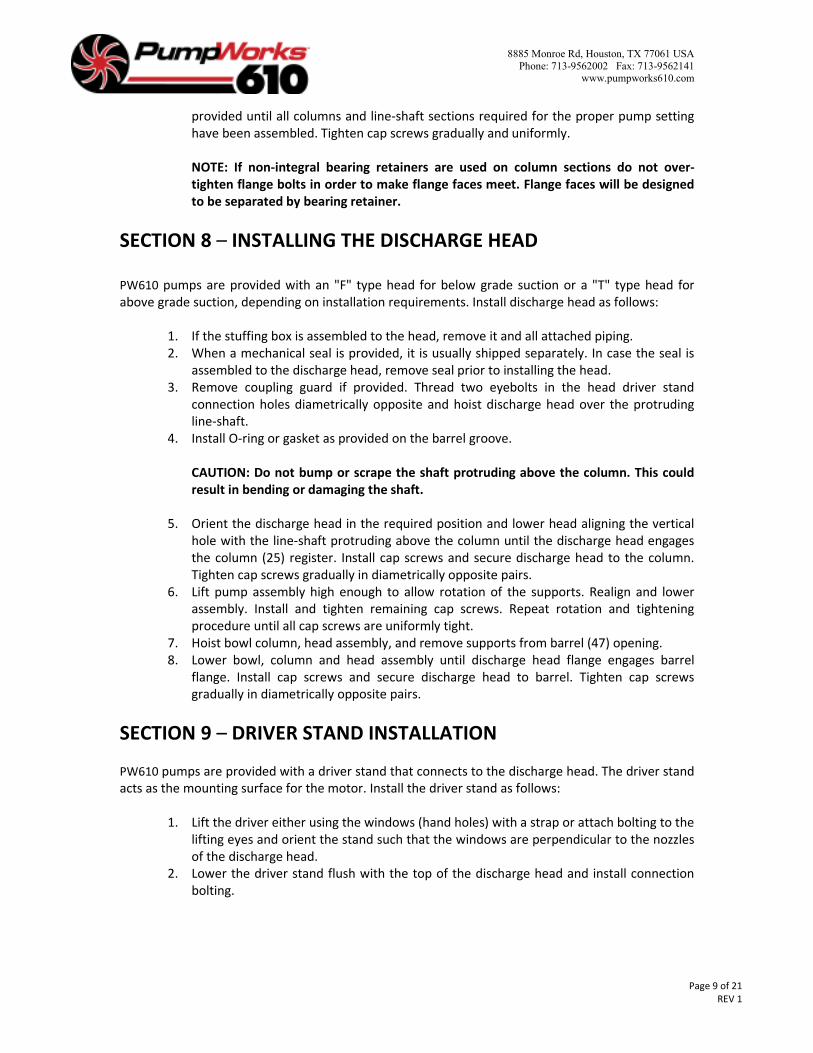
SECTION 8 – INSTALLING THE DISCHARGE HEAD
PW610 pumps are provided with an "F" type head for below grade suction or a "T" type head for
above grade suction, depending on installation requirements. Install discharge head as follows:
1. If the stuffing box is assembled to the head, remove it and all attached piping.
2. When a mechanical seal is provided, it is usually shipped separately. In case the seal is
assembled to the discharge head, remove seal prior to installing the head.
3. Remove coupling guard if provided. Thread two eyebolts in the head driver stand
connection holes diametrically opposite and hoist discharge head over the protruding
line-shaft.
4. Install O-ring or gasket as provided on the barrel groove.
CAUTION: Do not bump or scrape the shaft protruding above the column. This could
result in bending or damaging the shaft.
5. Orient the discharge head in the required position and lower head aligning the vertical
hole with the line-shaft protruding above the column until the discharge head engages
the column (25) register. Install cap screws and secure discharge head to the column.
Tighten cap screws gradually in diametrically opposite pairs.
6. Lift pump assembly high enough to allow rotation of the supports. Realign and lower
assembly. Install and tighten remaining cap screws. Repeat rotation and tightening
procedure until all cap screws are uniformly tight.
7. Hoist bowl column, head assembly, and remove supports from barrel (47) opening.
8. Lower bowl, column and head assembly until discharge head flange engages barrel
flange. Install cap screws and secure discharge head to barrel. Tighten cap screws
gradually in diametrically opposite pairs.
SECTION 9 – DRIVER STAND INSTALLATION
PW610 pumps are provided with a driver stand that connects to the discharge head. The driver stand
acts as the mounting surface for the motor. Install the driver stand as follows:
1. Lift the driver either using the windows (hand holes) with a strap or attach bolting to the
lifting eyes and orient the stand such that the windows are perpendicular to the nozzles
of the discharge head.
2. Lower the driver stand flush with the top of the discharge head and install connection
bolting.
8885 Monroe Rd, Houston, TX 77061 USA
Phone: 713-9562002 Fax: 713-9562141
www.pumpworks610.com
Page 10 of 21
REV 1
SECTION 10 – MECHANICAL SEAL INSTALLATION
Instructions for installing mechanical seals are provided by the seal manufacturer. Consult the seal
manufacturer's instructions (furnished with the seal) for information on the type of seal used.
Additionally, refer to factory furnished outline drawing and seal piping schematic for seal piping
arrangements.
SECTION 11 – DRIVER AND COUPLING INSTALLATION AND
INSTALLATION
INSTALLATION OF SOLID SHAFT DRIVER
NOTE: When pump is provided with a thrust pot, secure driver to discharge head and indicate line
up before installing the thrust pot and flexible coupling are installed.
WARNING: Do not work under a heavy suspended object unless there is a positive support under
it, which will protect personnel should a hoist or sling fail.
The coupling between the driver-shaft and line-shaft may be a nonspacer or a spacer type. The latter
is used on pumps furnished with a mechanical seal to permit servicing the seal without lifting the
driver.
Proceed with installation of the driver as follows:
1. Attach a sling to the lifting lugs of driver. Hoist motor, inspect the mounting surface,
register, and shaft extension, and clean these surfaces thoroughly. If any burrs are
found, remove burrs with a smooth mill file, cleaning thoroughly afterward.
2. Orient the motor conduit box in the required position and align the mounting holes with
the hating tapped holes in the discharge head. Lower the motor until the registers
engage and motor rests on the discharge head. Secure motor with cap screws provided.
3. Check assembly run-outs. Bore Max T.I.R 0.005” – Face Max T.I.R 0.002.
4. On drivers having a non-reverse ratchet or pins manually turn the driver shaft clockwise
viewed from above until the non-reverse ratchet or pins fully engage.
5. Lubricate motor bearings in accordance with instructions given on the lubrication plate
attached to the motor case.
WARNING: The motor must not be tested for direction of rotation when coupled to
the pump. If pump should rotate in the wrong direction, serious damage to the pump
and driver and serious Injury to nearby personnel could result.
6. Make temporary electrical connections according to tagged leads or diagram attached
to the motor. Motor must rotate counterclockwise when viewed from above. See arrow
on pump name plate, if driver does not rotate counterclockwise, change motor rotation
by interchanging any two leads, for three phase only. For single phase, see motor
manufacturer's instructions.
7. MOTOR SHAFT END PLAY ADJUSTMENT: Motor shaft end play if required shall be
checked with a dial indicator prior to connecting pump coupling to solid shaft motor.
Consult the applicable motor manufacturer’s instruction manual for detailed
information on motor shaft end play.

8885 Monroe Rd, Houston, TX 77061 USA
Phone: 713-9562002 Fax: 713-9562141
www.pumpworks610.com
Page 11 of 21
REV 1
8. Coupling Installation:
• Apply thin film of oil on line-shaft key (11) and insert key into line-shaft keyseat.
• Gently lower pump hub over head-shaft
• Thread adjusting nut (6) flush with top of head-shaft.
• Apply a thin film of oil to key and insert it into the driver shaft keyseat. Place the
driver hub (4) over the driveshaft and key sliding it up the shaft until annular groove
is exposed. Install split ring (12) in the groove and slide driver hub down over the
split ring to capture it.
• Install spacer (5) and secure to driver hub (4) with cap screws (8) and nuts (9)
IMPELLER ADJUSTMENT. Impeller adjustment is identical for motors and right angle gear drives.
Adjustment is accomplished by turning adjusting plate (6).
NOTES:
1. Mechanical seal, when provided must not be secured to the shaft prior to impeller adjustment
(open or enclosed impellers). Shaft must move up or down within the seal assembly.
2. For pumps handling liquids between -50 to 200°F, impeller adjustment can be made under
ambient conditions. For liquid temperatures in excess of this range, it is recommended that
Impeller adjustment be made after the pump surface temperature has reached an equilibrium
when charged with the pumpage. In those cases, where this is not feasible due to safety
considerations or impossible due to external ice buildup in cryogenic applications, refer to factory
for specific instructions.
3. When a thrust pot is used, impeller adjustment is accomplished with the pot's adjusting nut and
a dial indicator.
A. OPEN IMPELLERS
1. With the impellers at the bottom, turn adjusting nut (6) towards driver hub or spacer
(4). Obtain 0.015 inch clearance between adjusting plate and driver hub or spacer for
the first 10 feet of column. Add 0.010 for each additional 10 feet of column. EXAMPLE:
Total pump length 50 feet-set impellers at 0.055 inch.
2. After impeller adjustment, align adjusting plate (6) with pump hub (7), and tightly draw
coupling flanges together. This raises impellers amount of clearance between flanges.
3. Set seal after impeller adjustment. Securely tighten all setscrews in the collar. Remove
spacer between the gland plate and collar. Retain spacer for future resetting of seal.
NOTE: When impellers are reset, the seal must also be reset.
B. ENCLOSED IMPELLERS
1. The lifting setting for the pump will be found marked with a lifting tag below the
namplate for the pump. It can also be found on the Certified General Arrangement
Drawing. This setting should be 1/8 to 3/16 clearance between the adjusting nut and the
shaft. Shaft elongation will be compensated on pumps longer than 20ft.
2. After impeller adjustment, align adjusting nut (6) with pump hub (7) and spacer (5).
Insert cap screws (8) and tightly draw coupling flanges together.
3. To set seal, follow step A3, open impellers.

8885 Monroe Rd, Houston, TX 77061 USA
Phone: 713-9562002 Fax: 713-9562141
www.pumpworks610.com
Page 12 of 21
REV 1
SECTION 12 – PUMP STARTUP AND OPERATION
PRE-START PROCEDURE: Consult the applicable manufacturer's instructions for detailed information
for the prime mover (engine or steam turbine) coupling, driveshaft, electric driver, gearhead or
mechanical seal. When applicable to the pump and prior to startup, check the following:
1. Make sure mechanical seal is properly lubricated and all piping to seal connected. Also,
check that all cooling, heating and flushing lines are operating and regulated.
2. Check alignment between pump and driver.
3. Wiring of driver is counterclockwise when viewed from above.
4. All connections to driver and starting device with wiring diagram.
5. Voltage, phase, and frequency on motor nameplate with line circuit.
6. Impeller adjustment.
7. Rotate shaft manually to ensure impellers are not binding.
8. Check that driver bearings are properly lubricated and check oil level in housing.
9. Check that Barrel and auxiliary seal components are properly vented.
NOTE: Particularly on pumping fluids that are near their vapor pressure, adequate
venting is a must for reliable pump operation. The barrel should be continuously
vented back to the vapor side of the suction vessel with liberal size piping.
Additionally, on systems where the suction pressure is below atmospheric pressure
and a standby pump is not isolated from the system, precautions must be taken, to
prevent the entrance of air. This is generally handled by pressurizing the standby
pump from the system's discharge pressure side, through the pump stuffing box or seal
housing.
10. Check Discharge piping and pressure gages for proper operation.
PRIMING
The first stage must always be completely submerged. Pump must not run dry, the rotating parts
within the pump may gall and seize to the stationary parts. The parts must be lubricated by the liquid
being pumped.
PUMP STARTUP
1. Partially close valve in discharge line.
2. Fully open suction side valves on pressurized systems.
3. Vent system when the pump surface temperature has reached an equilibrium.
4. Start pump.
5. When pump is operating at full speed, slowly open discharge valve. If driver overheats
or there is excessive vibration, stop the pump.
NOTE: If the Impellers have not been final adjusted, due to extreme liquid
temperature, they should be adjusted prior to start-up and after pump surface
temperatures have reached an equilibrium.

8885 Monroe Rd, Houston, TX 77061 USA
Phone: 713-9562002 Fax: 713-9562141
www.pumpworks610.com
Page 13 of 21
REV 1
MECHANICAL SEAL
If seal leaks slightly at startup, allow a reasonable amount of time for seal to adjust itself.
Liquids with good lubricating qualities normally take longer to wear in the seal than liquid with lesser
qualities. When a seal starts out with a slight leak and gets progressively less with running, it is
indicative of leakage across the seal faces and that continued running will eliminate leakage. Where
leakage occurs immediately and remains constant, unaffected by running, it usually indicates
secondary seal (shaft packing) damage, or seal faces are warped out of flat.
SECTION 13 – MAINTENANCE
Preventive maintenance includes periodic inspection, re-lubrication of electric motors, gear drives
and prime mover. Systematic inspection of the pump and its components shall be made at regular
intervals. The frequency required depends upon the operating conditions of the pump and its
environment. Consult the applicable manufacturer's instructions for detailed information on
maintenance for the prime mover, driveshaft, electric motors and gear drives. Any deviation in
performance or operation from what is expected can be traced to some specific cause. Variances
from initial performance will indicate changing system conditions, wear, or impending breakdown of
the unit.
WARNING: Before initiating maintenance procedures disconnect all power sources to the
equipment and accessories and completely discharge all parts and accessories which may retain
electric charge. Failure to comply may result in severe personal injury or death.
SECTION 14 – TROUBLESHOOTING
Corrective maintenance procedures include functions of the pump and its components during
troubleshooting for isolating and remedying bad operation. Before pulling the pump bowl from
the well, the Installation and Operation Manual should be reviewed for causes of reduced
performance not related to the condition of the bowl assembly. Some of the possible causes of
reduced performance could be:
1. Incorrect lateral adjustment. (This is especially critical with units utilizing semi-open
impellers).
2. Well conditions such as gas or air in the water.
3. Change in operating conditions such as increased pumping water level or increased
discharge head requirements.
4. Slow motor speed due to overload, low voltage or low frequency.
5. Incorrect direction of rotation.
6. Strainer clogged or suction “sanded in”.
7. Inadequate submergence of pump suction.
After the pump bowls have been pulled but before sending to the shop for repairs,
check the bottom impeller for foreign material such as rocks or wood chips. Also check
the strainer for obstructions.

8885 Monroe Rd, Houston, TX 77061 USA
Phone: 713-9562002 Fax: 713-9562141
www.pumpworks610.com
Page 14 of 21
REV 1
SECTION 15 – PUMP DISASSEMBLY AND REASSEMBLY
PUMP DISASSEMEBLY
NOTE: Pump components should be match marked prior to disassembly
Clear a large area adjacent to the pump as a storage space for pump parts as they are disassembled.
If the pump has a long column, arrange parallel timbers on the ground to support the pump column
and shaft sections horizontally. After disassembly for repair or replacement of pump components,
reassemble in all cases.
WARNING: Do not attempt to lift the entire pump by the lifting lugs of the driver. These lugs and
bolts cannot support the weight of the entire pump.
CAUTION: When lifting the pump use the appropriate lifting eyes located on the driver stand. In
the case where the pump exceeds 20,000 lbs, consider dissassembly by components.
It is recommended that maintenance personnel become thoroughly familiar with the PW610 pump
before performing any removal of the components. Consult the manufacturer’s instructions for
detailed disassembly information for the prime mover, driveshaft, gear drive, motor and mechanical
seal, as applicable.
1. On pumps which are driven through a gear drive remove driveshaft between the gear
drive and prime mover on. Pumps equipped with an electric motor drive, remove the
electrical connection at the conduit box and tag electrical leads at the motor.
WARNING: Before opening the conduit box of an electrical motor, be sure that the
current to the motor is shut off. Severe injury to personnel could result If contact with
live motor leads Is made.
2. Match mark parts in sequence of disassembly to aid in the reassembly procedure.
3. Disconnect the discharge piping from discharge head. If driver is equipped with an oil-
cooling system, remove the external tubing or piping as required.
SOLID SHAFT DRIVER REMOVAL
1. Remove nuts (9) and cap screws (8) and disconnect spacer or nonspacer coupling as
applicable. See Annex A for Cross Sections. 2. Remove cap screws that secure driver to discharge head or driver support (1) and lift
driver off the discharge head, or driver support.
3. Remove nuts (9), cap screws (8), spacer (5), unscrew adjusting plate (6), pump hub (7),
driver hub (4), remove keys (10 and 11) and split ring (12).
WARNING: Do not work under a heavy suspended object unless there is a positive
support under it which will protect personnel should a hoist or sling fail.
4. DRIVER SHAFT END PLAY. When the driver, solid shaft motor or gear drive is
disassembled, shaft end play shall be checked with dial indicator prior to connecting

8885 Monroe Rd, Houston, TX 77061 USA
Phone: 713-9562002 Fax: 713-9562141
www.pumpworks610.com
Page 15 of 21
REV 1
pump coupling to the applicable driver. Consult the applicable driver manufacturer's
instruction manual for detailed information on shaft end play adjustment.
MECHANICAL SEAL REMOVAL
Instructions for each seal are provided with the seal, if instructions are not available, the following
information applies for most seals furnished:
1. INSIDE MOUNTED SEAL-If seal is provided with eccentric washers, swing them into the
slot in the sleeve and lock them into position before loosening setscrews, so that seal
may be reset. If the seal does not have eccentric washers or a spacer, mark position of
seal using a flat scribing tool; before loosening setscrews. Remove gland cap screws, and
slide seal off the shaft.
2. DOUBLE SEAL-If seal is provided with eccentric washers swing them into the slot in the
sleeve and lock them into position before loosening setscrews. Remove cap screws that
secure gland. Carefully slide gland, rotating unit and stationary seat, to ensure not to
damage gaskets and O-rings.
3. TANDEM SEAL-If seal is provided with eccentric washers, swing them into the slot in the
sleeve and lock them into position before loosening setscrews, so that seal may be
reset, If the seal does not have eccentric washers or a spacer, mark position of seal using
a flat scribing tool, before loosening setscrews. Remove gland cap screws, and slide seal
off the shaft.
DISCHARGE HEAD AND COLUMN REMOVAL
1. Remove cap screws (46) that secure discharge head to barrel.
2. If pump is provided with a driver support (1) remove cap screws (2) and hoist off the
discharge head.
3. Pass two slings through hand holes on discharge head or place an elevator clamp
just below the discharge head flange, if discharge does not have hand holes and
hoist entire pump straight upward to a comfortable working height. Fasten an
elevator clamp approximately two feet below the column (25). Place two I-beams
across the barrel opening. Lower pump until the elevator clamp rests on the I-
beams.
4. Remove cap screws (26) and hoist discharge head off the top column (25). Remove
bearing retainer if applicable.
5. Attach the sling to the elevator clamp and raise pump until the next column flange is
above the barrel flange. Fasten another elevator clamp below the next column
flange and lower the pump until elevator clamp rests on the I-beams and remove
the sling.
6. Disconnect line-shaft from threaded coupling and remove from lineshaft (13).
Remove coupling and remove bearing retainer.
NOTE: Shaft threads are left hand. CAUTION: If threaded coupling will not readily
unscrew, apply heat to coupling (not to shaft), for approximately 30 seconds, at
the same time applying torque to the shaft.

8885 Monroe Rd, Houston, TX 77061 USA
Phone: 713-9562002 Fax: 713-9562141
www.pumpworks610.com
Page 16 of 21
REV 1
7. Disconnect additional lengths of column and lineshafts as required until top bowl
(31) is reached.
8. Install two eyebolts diametrically opposite in bowl assembly. Attach a sling to
eyebolts and to hoist hook. Hoist bowl assembly and place horizontally on blocks.
BOWL DISASSEMBLY. The bowl assembly is composed of a suction bell, intermediate bowl, top
bowl, enclosed impellers with taper collets, enclosed impellers with thrust collars, bearings and
a barrel.
NOTE: Match mark bowl assembly In sequence of disassembly to aid In the reassembly
procedure.
TURBINE BOWLS. Turbine bowl impellers are secured to the shaft by either a taper collet or by
standard key construction.
TURBINE BOWL-WEAR RINGS REMOVAL
1. Utilizing a diamond point chisel, cut two "V" shape grooves on the bowl wear ring
approximately 180 degrees apart. Use extreme care not to damage the wear ring
seat.
2. With a chisel or equal, knock the end of one half of the ring in and pry ring out.
3. On special materials, such as chrome steel, set up the bowl in a lathe and machine
the wear ring off. Use extreme care not to machine or damage the ring seat.
TURBINE BOWL-IMPELLER WEAR RING REMOVAL
Set up impeller in a lathe and machine wear ring off. Use extreme care not to machine or
damage ring seat or impeller hub.
BOWL, SUCTION BELL AND RETAINER BEARING REMOVAL
1. Utilizing an arbor press and a piece of pipe or sleeve with outside diameter slightly
smaller than bowl and retainer bearing housing, press the bearing off.
2. Remove suction bell bearing by setting suction bell on a lathe and machine bearing
off. Suction bell bearing may also be removed by using bearing pullers and pulling
bearing out.
NOTE: Bowl bearings are press fit. Do not remove unless replacement Is necessary.
INSPECTION AND REPLACEMENT
1. Clean all pump parts thoroughly with a suitable cleaner.
2. Check bearing retainers for deformation and wear.
3. Check shafts for straightness and excessive wear on bearing surfaces. Check
deflection of shafts; average total runout shall not exceed 0.003” T.I.R
8885 Monroe Rd, Houston, TX 77061 USA
Phone: 713-9562002 Fax: 713-9562141
www.pumpworks610.com
Page 17 of 21
REV 1
4. On pumps equipped with a mechanical seal, check that shaft or sleeve is free of pits,
burrs or sharp edges to prevent cutting or improper sealing of O-ring. Remove burrs
and sharp edges by polishing with a fine crocus cloth.
5. Visually check impellers and bowls for cracks and pitting. Check all bowl bearings for
excessive wear and corrosion.
6. Replace all badly worn or damaged parts with new parts. In addition, replace all
gaskets, o-rings and packing as required.
TURBINE BOWL AND IMPELLER WEAR RING INSTALLATION
Place the bowl on a flat surface with the flange side facing up. Use liquid nitrogen or other
method to shrink wear rings and drop in. Press until the wear ring face is even with the bowl
bore face. Cast Iron or materials that are not easily fused should be secured with installation
pins. 400 series stainless or other materials that can be fused should be welded in place to
secure them.
Impellers should be placed on a flat surface with the eye side facing up. Heat impeller wear rings
until they expand and then drop them on impeller (certain materials should not be heated or
heated too long, especially wear rings with coatings). Press until flush. As before, use installation
pins where appropriate or fuse wear rings where appropriate.
BOWL, SUCTION BELL, AND RETAINER BEARING INSTALLATION
1. Press bearing (28) into spider using an arbor press or equal. See Annex A for Cross
Sections.
2. Press bearing (42) into suction bell (41) using an arbor press or equal.
3. Press bearings (33) into bowl (31). Place the bowl with the flange downward and
press bearing through chamfered side of bowl hub until bearing is flush with hub,
use an arbor press or equal.
4. For running-installed clearances see Annex “B”

8885 Monroe Rd, Houston, TX 77061 USA
Phone: 713-9562002 Fax: 713-9562141
www.pumpworks610.com
Page 18 of 21
REV 1
ANNEX “A” VS-6 & VS-1 CROSS SECTIONS

8885 Monroe Rd, Houston, TX 77061 USA
Phone: 713-9562002 Fax: 713-9562141
www.pumpworks610.com
Page 19 of 21
REV 1

8885 Monroe Rd, Houston, TX 77061 USA
Phone: 713-9562002 Fax: 713-9562141
www.pumpworks610.com
Page 20 of 21
REV 1

8885 Monroe Rd, Houston, TX 77061 USA
Phone: 713-9562002 Fax: 713-9562141
www.pumpworks610.com
Page 21 of 21
REV 1
ANNEX “B”
PWV RUNNING-INSTALLED CLARENCES
PUMP
SIZE
SHAFT DIA. NOMINAL DIAMETRICAL
CLEARNACE – SHAFT TO
BEARING
NOMINAL DIAMETRICAL
CLEARANCE – IMPELLER
WEAR RING TO BOWL
WEAR RING
AXIAL
CLEARANCE
END PLAY
6LK 1 0.006-0.008 0.011-0.013 1/4
6JO 1 0.006-0.008 0.011-0.013 7/16
6JK 1 0.006-0.008 0.011-0.013 3/8
7YK 1 0.006-0.008 0.014-0.016 3/8
8FK 1 3/16 0.006-0.008 0.014-0.016 3/8
8JK 1 3/16 0.006-0.008 0.014-0.016 9/16
8J0 1 3/16 0.006-0.008 0.014-0.016 9/16
8LK 1 3/16 0.006-0.008 0.014-0.016 7/15
8XK 1 3/16 0.006-0.008 0.014-0.016 7/16
10LK 1 1/2 0.007-0.009 0.015-0.017 1/2
10JK 1 1/2 0.007-0.009 0.015-0.017 1/2
10XK 1 1/2 0.007-0.009 0.015-0.017 1/2
10DO 1 1/2 0.007-0.009 0.015-0.017 1/2
10DK 1 1/2 0.007-0.009 0.015-0.017 9/16
10HK 1 1/2 0.007-0.009 0.015-0.017 7/8
10FK 1 11/16 0.007-0.009 0.015-0.017 9/16
11JK 1 11/16 0.007-0.009 0.016-0.018 9/16
12LK 1 11/16 0.007-0.009 0.016-0.018 1/2
12DO 1 11/16 0.007-0.009 0.016-0.018 5/8
12DK 1 11/16 0.007-0.009 0.016-0.018 5/8
12FK 1 11/16 0.007-0.009 0.016-0.018 1/2
14LK 1 15/16 0.007-0.009 0.017-0.019 5/8
14JK 1 15/16 0.007-0.009 0.017-0.019 5/8
14DO 1 15/16 0.007-0.009 0.017-0.019 3/4
14DK 1 15/16 0.007-0.009 0.017-0.019 7/8
14FK 1 15/16 0.007-0.009 0.017-0.019 1
15DK 2 1/4 0.010-0.012 0.018-0.020 7/8
16MK 2 1/4 0.010-0.012 0.019-0.021 9/16
18MK 2 1/4 0.010-0.012 0.020-0.022 5/8
20MK 2 7/16 0.011-0.013 0.021-0.023 3/4
22BK 2 7/16 0.011-0.013 0.022-0.024 11/4
Note: All dimensions in inches