Embed Size (px)
Citation preview
miniDSP Ltd, Hong Kong / www.minidsp.com / Features and speci fications subject to change without prior notice 1
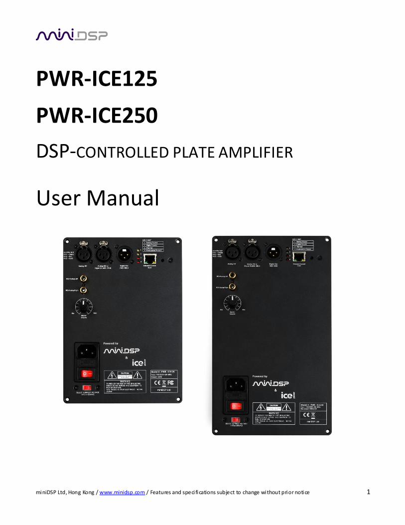
PWR-ICE125
PWR-ICE250
DSP-CONTROLLED PLATE AMPLIFIER
User Manual

miniDSP Ltd, Hong Kong / www.minidsp.com / Features and speci fications subject to change without prior notice 2
Revision history
Revision Description Date
V1.0 Initial revision 28-06-2013 V1.1 Updated typo on wiring 24-07-2013 V2.0 Merged PWR-ICE125 and PWR-ICE250; completely revised 31 August 2016 V2.1 Added 48k (FIR) plugin, new Master Volume selection 18 November 2016
V2.2 Changed plugin name 25 November 2016
miniDSP Ltd, Hong Kong / www.minidsp.com / Features and speci fications subject to change without prior notice 3
CONTENTS
Important Information ....................................................................................................................................5
System Requirements..................................................................................................................................5
Disclaimer/Warning ....................................................................................................................................6
Warranty Terms ..........................................................................................................................................6
Safety Instructions ..........................................................................................................................................7
1 Product Overview ................................................................................................................................... 10
1.1 The miniDSP concept ..................................................................................................................... 11
1.2 Choosing a plugin........................................................................................................................... 11
2 Installation and Setup ............................................................................................................................. 12
2.1 Installation ― Windows ................................................................................................................. 13
2.1.1 Possible Windows installation issues........................................................................................ 13
2.1.2 Plugin installation ................................................................................................................... 13
2.2 Installation ― Mac OS X ................................................................................................................. 14
2.2.1 Possible Mac installation issues ............................................................................................... 14
2.2.2 Plugin installation ................................................................................................................... 14
3 Hardware connectivity ............................................................................................................................ 15
3.1 High voltage WARNING .................................................................................................................. 15
3.2 Main panel .................................................................................................................................... 16
3.3 AC Power ...................................................................................................................................... 17
3.4 Analog audio input......................................................................................................................... 18
3.4.1 Input sensitivity jumpers ......................................................................................................... 18
3.5 Digital audio input and link/passthrough (AES/EBU) ......................................................................... 19
3.6 Ethernet ........................................................................................................................................ 20
3.7 Speaker connections ...................................................................................................................... 21
3.7.1 Output level jumper................................................................................................................ 21
4 Configuring the PWR-ICE Amplifiers ......................................................................................................... 22
4.1 Connecting to a PWR-ICE amplifier ................................................................................................. 23
4.2 Mismatched plugins ....................................................................................................................... 24
4.3 Renaming an AMPLIFIER................................................................................................................. 25
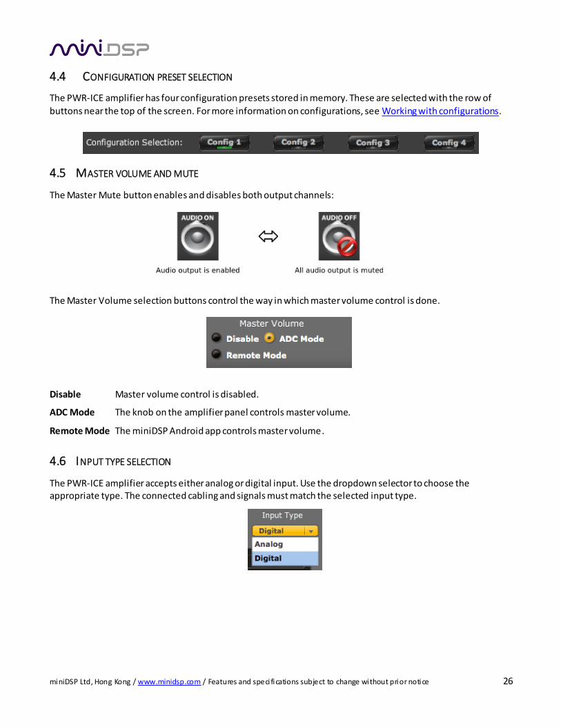
4.4 Configuration preset selection ........................................................................................................ 26
4.5 Master volume and mute ............................................................................................................... 26
4.6 Input type selection ....................................................................................................................... 26
4.7 Channel mode ............................................................................................................................... 27
4.8 Amplifier mode.............................................................................................................................. 28
4.9 Mode combinations ....................................................................................................................... 29
4.10 Input channel configuration............................................................................................................ 30
4.10.1 Channel label ......................................................................................................................... 30
4.10.2 Gain adjustment and level monitoring ..................................................................................... 30
4.10.3 Parametric EQ ........................................................................................................................ 30
4.11 Output channel configuration ......................................................................................................... 31
4.11.1 Channel label ......................................................................................................................... 31
miniDSP Ltd, Hong Kong / www.minidsp.com / Features and speci fications subject to change without prior notice 4
4.11.2 Gain adjustment and level monitoring ..................................................................................... 31
4.11.3 Processing blocks.................................................................................................................... 31
4.11.4 Mute...................................................................................................................................... 32
4.11.5 Invert ..................................................................................................................................... 32
4.11.6 Time delay ............................................................................................................................. 32
4.12 Working with configurations........................................................................................................... 33
4.12.1 Selecting a configuration preset .............................................................................................. 33
4.12.2 Synchronization options.......................................................................................................... 33
4.12.3 Saving and loading configurations............................................................................................ 34
4.12.4 Restoring to defaults............................................................................................................... 35
4.13 Keyboard Shortcuts........................................................................................................................ 35
5 Signal Processing Functions ..................................................................................................................... 36
5.1 Parametric EQ ............................................................................................................................... 36
5.2 Crossover (96k plugin only) ............................................................................................................ 38
5.3 FIR filtering and design (FIR plugin only) .......................................................................................... 39
5.3.1 FIR filtering overview .............................................................................................................. 40
5.3.2 FIR filter design software......................................................................................................... 40
5.3.3 Filter file format ..................................................................................................................... 41
5.3.4 Loading filter coefficients ........................................................................................................ 41
5.4 Custom biquad programming ......................................................................................................... 42
5.4.1 What’s a “biquad? .................................................................................................................. 42
5.4.2 Using custom biquad programming ......................................................................................... 42
5.4.3 Biquad calculation spreadsheet ............................................................................................... 43
5.4.4 Room EQ Wizard (REW) .......................................................................................................... 43
5.5 Compressor ................................................................................................................................... 44
6 Additional Information............................................................................................................................ 45
6.1 Key Specifications .......................................................................................................................... 45
6.1.1 General .................................................................................................................................. 45
6.1.2 PWR-ICE125 ........................................................................................................................... 45
6.1.3 PWR-ICE250 ........................................................................................................................... 45
6.2 Mounting dimensions .................................................................................................................... 46
6.2.1 PWR-ICE125 ........................................................................................................................... 46
6.2.2 PWR-ICE250 ........................................................................................................................... 48
6.2.3 Additional mounting considerations ........................................................................................ 50
6.3 MCU Firmware upgrade ................................................................................................................. 51
6.3.1 Put the amp into bootloader mode.......................................................................................... 51
6.3.2 Windows................................................................................................................................ 51
6.3.3 Mac ....................................................................................................................................... 52
6.4 Troubleshooting ............................................................................................................................ 53
6.5 Obtaining Support.......................................................................................................................... 54

miniDSP Ltd, Hong Kong / www.minidsp.com / Features and speci fications subject to change without prior notice 5
IMPORTANT INFORMATION
Please read the following information before use. In case of any questions, please contact miniDSP via the
support portal at minidsp.desk.com.
SYSTEM REQUIREMENTS
To configure the PWR-ICE amplifiers, you will require a Windows PC or Apple Mac OS X computer with the
following minimum specification:
Windows
PC with 1GHz or higher processor clock speed. Intel® Pentium®/Celeron® family, or AMD K6®/AMD
Athlon®/AMD Duron® family, or compatible processor recommended.
512 megabytes (MB) of RAM or higher
Keyboard and mouse or compatible pointing device
Microsoft• ® Windows® Vista® SP1/ XP pro SP2/Win7/Win8.1/Win10
Microsoft• ® .NET framework v3.5 or later
Adobe AIR environment (latest version)
Adobe Flash player (latest version)
Mac OS X
Intel-based Mac with 1 GHz or higher processor clock speed
512 megabytes (MB) of RAM or higher
Keyboard and mouse or compatible pointing device
Mac OS X 10.8 or higher
Adobe AIR environment (latest version)
Adobe Flash player (latest version)
Both Platforms
For Ethernet connectivity via LAN:
Ethernet router with spare 100 Mbps port
For direct (ZeroConf) Ethernet connectivity:
Ethernet port on computer with 100 Mbps capability. (Recent Apple Macs: a Thunderbolt port with a
Thunderbolt to Ethernet adapter.)

miniDSP Ltd, Hong Kong / www.minidsp.com / Features and speci fications subject to change without prior notice 6
D ISCLAIMER/WARNING
miniDSP cannot be held responsible for any damage that may result from the improper use of this product or
incorrect configuration of its settings. As with any other product, we recommend that you carefully read this
manual and other technical notes to ensure that you fully understand how to operate this product. The PWR-ICE
amplifier is a powerful tool, and misuse or mis-configuration, such as incorrectly set gains or excessive boost, can produce signals that may damage your audio system.
As a general guideline, you should perform the initial configuration of your PWR-ICE amplifier before enabling
audio through any connected output device or amplification. Doing so will help ensure that the software is
correctly configured.
Finally, note that the PWR-ICE amplifier is a very flexible device, and many of the questions we receive at the
tech support department are already answered in this user manual and in the online application notes on the
miniDSP.com website. So please take the time to carefully read this user manual and the online technical support. Thanks for your understanding!
WARRANTY TERMS
miniDSP Ltd warrants this product to be free from defects in materials and workmanship for a period of one
year from the invoice date. Our warranty does not cover failure of the product due to incorrect connection or
installation, improper or undocumented use, unauthorized servicing, modification or alteration of the unit in any way, or any usage outside of that recommended in this manual. If in doubt, contact miniDSP prior to use.

miniDSP Ltd, Hong Kong / www.minidsp.com / Features and speci fications subject to change without prior notice 7
SAFETY INSTRUCTIONS
• Read the information for use
• Please keep this user manual in a safe place during the lifetime of the product. The user manual forms an
integral part of the product. Reselling of the product is only possible if the user manual is available. Any changes made to the product have to be documented in writing and passed on to the buyer in the event of resale.
• Heed all warnings.
• Follow all instructions.
• Do not use this product near water (for example, in damp rooms or near a swimming pool).
• Clean only with dry cloth.
• Do not cover the heat sink. Install in accordance with the user manual.
• Do not install near any heat sources such as radiators, heat registers, stoves, or other apparatus that produce
heat.
• Protect the power cord from being walked on, pinched or damaged in any other way. Pay particular attention to plugs and the point where they exit from the Amplifier Unit.
• The product may only be used in accordance with the information provided in the user manual. Before and
during the usage of the amplifier please ensure that all recommendations, especially the safety
recommendations as detailed in the user manual, are adhered to. The Amplifier Unit is designed for the
amplification of pulsed audio signals and the Amplifier Unit should only be connected to speakers with average
impedance that is not lower than the impedances specified in the User's Manual.
• Do not place the product on an unstable cart, stand, tripod, bracket, or table. The device may fall, causing
serious injury, and serious damage to the device itself.
• The Amplifier Unit can only be disconnected from the power supply by removing the plug, which must be
freely accessible at all times. Unplug this Amplifier Unit during lightning storms or when unused for long periods
of time.
• Refer all servicing to qualified service personnel.
Damages that require service
Unplug the Amplifier Unit from the mains supply and refer to your dealer/distributor or other authorized repair
workshop. Servicing is required when
1. The power-supply cord or plug has been damaged, 2. Liquid has been spilled or objects have fallen into the amplifier, 3. The amplifier has been exposed to rain or moisture, 4. The amplifier has been dropped or suffered damage in any other way, 5. The amplifier exhibits a distinct change from its normal function or performance.
miniDSP Ltd, Hong Kong / www.minidsp.com / Features and speci fications subject to change without prior notice 8
Servicing
Do not attempt to service this product yourself. As opening or removing covers may expose you to dangerous
voltage or other hazards, the amplifier may only be opened by qualified personnel. Please refer to your
dealer/distributor.
Servicing and Replacement Parts
All service and repair work must be carried out by an authorized dealer/distributor. When replacement parts are
required, please ensure that the dealer/distributor only uses replacement parts specified by the manufacturer. The use of unauthorized replacement parts may result in injury and/or damage through fire or electric shock or
other electricity-related hazards.
Safety Check
Upon completion of any service or repairs to this product, ask the dealer/distributor to perform safety checks to
determine that the amplifier is in proper operating condition.
Read the information for use (user manual)
When shipping the product, always use the original shipping carton and packing materials. For maximum
protection, repack the unit as it was originally packed at the factory.
Environments
Use this product only in E1, E2, E3 or E4 environments according to EN55103-2 “Electromagnetic compatibility –
Product family standard for audio, video and audio-visual and entertainment lighting control apparatus for
professional use – Part 2: Immunity”
Ventilation and heat sink
The heat sink is provided to ensure reliable operation of the Amplifier Unit and to protect it from overheating.
The heat sink must not be blocked or covered. This product should not be installed unless proper ventilation is
provided or manufacturer’s instructions have been adhered to.
Water And Moisture
Do not use this product near water (for example, in damp rooms or near a swimming pool).
Cleaning
Unplug the Amplifier Unit from the wall outlet before cleaning. Do not use l iquid or aerosol cleaners.
Power-cord Protection
Power supply cords should be routed so that they are not likely to be walked on or pinched by items placed upon them or against them, paying particular attention to cords and plugs, and the point where they exit from
the Amplifier Unit.
Lightning
For added protection of the product during lightning storms, or when it is left unattended and unused for long
periods of time, unplug it from the wall outlet. This will prevent damage to the product due to lightning and
power-line surges. Disconnection from the mains power supply can only be achieved by removing the plug from
the mains socket and by external disconnection of all poles from the mains.

miniDSP Ltd, Hong Kong / www.minidsp.com / Features and speci fications subject to change without prior notice 9
Interference of external objects and/or liquids with the appliance
Never push objects of any kind into this product through openings as they may touch dangerous voltage points
or short out parts that could result in a fire or electric shock. Never spill liquid of any kind on the amplifier.
Accessories
Do not place this product on an unstable cart, stand, tripod, bracket, or table. The product may fall, causing
serious injury, and serious damage to the product. Any mounting of the product should follow the
manufacturer’s instructions, and should use a mounting accessory recommended by the manufacturer.
Connecting
When you connect the Amplifier Unit to other equipment, turn off the power and unplug all of the equipment
from the supply source. Failure to do so may cause an electric shock and serious personal injury. Read the user's
manual of the other equipment carefully and follow the instructions when making the connections..
Sound Volume
Reduce the volume to minimum before you turn on the amplifier to prevent sudden high levels of noise which
may cause hearing or speaker damage.
Output connectors
WARNING: Output connector marked with the lightning flashes indicate high voltages that are potentially life threatening. Wiring to these terminals requires installation by an instructed person and the use
of ready-made leads or cords. Custom wiring should only be carried out by qualified personnel.
To prevent electric shock, do not operate the product with any of the conductor portion of the speaker wire
exposed.
NOTE: For reasons of safety and performance, use only high-quality fully insulated speaker cables of stranded
copper wire. Use the largest wire size that is economically and physically practical, and make sure the cables are no longer than necessary.
Precautions when connecting to MAINS IN
When mounting or connecting the product always disconnect it from mains. Only connect the product to an
appropriate AC circuit and outlet, according to the requirements indicated on the rating plate.
If a power cut occurs while the amplifier is switched on, it will restart automatically once the power supply has
been restored. All settings prior to the loss of power will be maintained.
IMPORTANT: Always connect the Product to mains through the MAINS IN connector on the Amplifier Unit.
DO NOT REMOVE MAINS CONNECTOR GROUND, IT IS ILLEGAL AND DANGEROUS.
miniDSP Ltd, Hong Kong / www.minidsp.com / Features and speci fications subject to change without prior notice 10
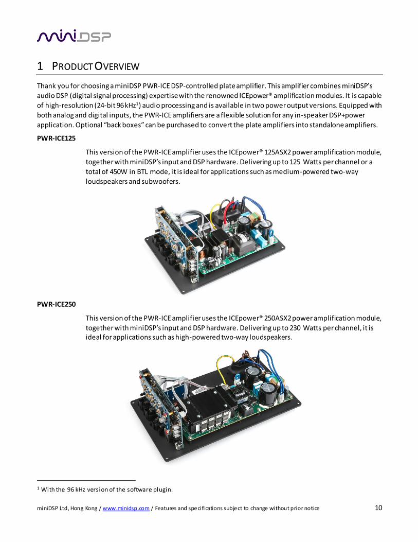
1 PRODUCT OVERVIEW
Thank you for choosing a miniDSP PWR-ICE DSP-controlled plate amplifier. This amplifier combines miniDSP’s
audio DSP (digital signal processing) expertise with the renowned ICEpower® amplification modules. It is capable
of high-resolution (24-bit 96 kHz1) audio processing and is available in two power output versions. Equipped with
both analog and digital inputs, the PWR-ICE amplifiers are a flexible solution for any in-speaker DSP+power
application. Optional “back boxes” can be purchased to convert the plate amplifiers into standalone amplifiers.
PWR-ICE125
This version of the PWR-ICE amplifier uses the ICEpower® 125ASX2 power amplification module,
together with miniDSP’s input and DSP hardware. Delivering up to 125 Watts per channel or a
total of 450W in BTL mode, it is ideal for applications such as medium-powered two-way
loudspeakers and subwoofers.
PWR-ICE250
This version of the PWR-ICE amplifier uses the ICEpower® 250ASX2 power amplification module,
together with miniDSP’s input and DSP hardware. Delivering up to 230 Watts per channel, it is ideal for applications such as high-powered two-way loudspeakers.
1 With the 96 kHz version of the software plugin.
miniDSP Ltd, Hong Kong / www.minidsp.com / Features and speci fications subject to change without prior notice 11
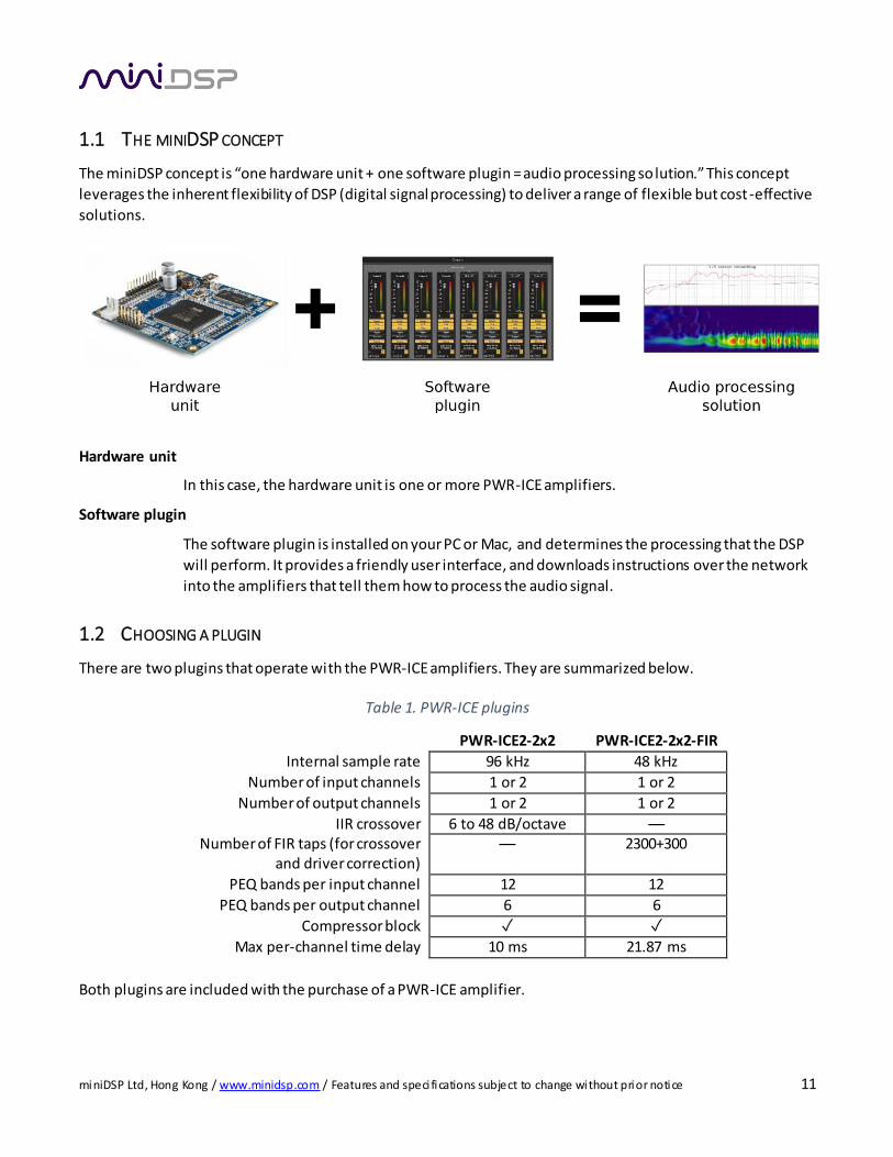
1.1 THE MINIDSP CONCEPT
The miniDSP concept is “one hardware unit + one software plugin = audio processing so lution.” This concept
leverages the inherent flexibility of DSP (digital signal processing) to deliver a range of flexible but cost -effective
solutions.
Hardware unit
In this case, the hardware unit is one or more PWR-ICE amplifiers.
Software plugin
The software plugin is installed on your PC or Mac, and determines the processing that the DSP
will perform. It provides a friendly user interface, and downloads instructions over the network
into the amplifiers that tell them how to process the audio signal.
1.2 CHOOSING A PLUGIN
There are two plugins that operate with the PWR-ICE amplifiers. They are summarized below.
Table 1. PWR-ICE plugins
PWR-ICE2-2x2 PWR-ICE2-2x2-FIR
Internal sample rate 96 kHz 48 kHz
Number of input channels 1 or 2 1 or 2
Number of output channels 1 or 2 1 or 2
IIR crossover 6 to 48 dB/octave — Number of FIR taps (for crossover
and driver correction) — 2300+300
PEQ bands per input channel 12 12
PEQ bands per output channel 6 6
Compressor block
Max per-channel time delay 10 ms 21.87 ms
Both plugins are included with the purchase of a PWR-ICE amplifier.

miniDSP Ltd, Hong Kong / www.minidsp.com / Features and speci fications subject to change without prior notice 12
2 INSTALLATION AND SETUP
If you purchased your product directly from miniDSP, your software will be available from the User Downloads
section of the miniDSP website when your order ships. To access the download, you will need to be logged into
the website with the account you created when purchasing96k plugin.
If you purchased your product from a miniDSP dealer, you will receive a coupon together with the product.
Redeem this coupon and select the Plugin Group “PWR-ICE125/250” at the link below:
https://www.minidsp.com/support/redeem-coupon
The User Downloads link is visible from the dropdown menu at the top right of the website page:
Navigate to the PWR-DSP/PWR-ICE software section. There you will find two packages available for download:
PWR-ICE 2x2 plug-in - Mac&Windows support
This will install the PWR-ICE2-2x2 plugin. This manual will refer to this plugin as the “96k plugin.”
Download this file for both Windows and Mac.
PWR-ICE 2x2 FIR plug-in
This will install the PWR-ICE2-2x2-FIR plugin. This manual will refer to this plugin as the “FIR plugin.” Download this file for both Windows and Mac.
After downloading, unzip the downloaded files (on Windows, right-click and select “Extract All...”; on Mac,
double-click).

miniDSP Ltd, Hong Kong / www.minidsp.com / Features and speci fications subject to change without prior notice 13
2.1 INSTALLATION ― WINDOWS
2.1.1 Possible Windows installation issues
The miniDSP software requires that a number of other frameworks be installed for it to work. For Windows 7 and later, these packages should be installed automatically. For earlier versions of Windows, please download
and install the following frameworks before attempting to install any miniDSP software. You can also manually
install these if you receive an error message that required software is missing.
Microsoft .NET framework (version 3.5 or later)
Latest version of Adobe Air
Microsoft Visual C++ 2010 Redistributable Package: for x86 (32-bit operating system) or x64 (64-bit operating system).
2.1.2 Plugin installation
Note: if you are upgrading from version 1.2 or earlier of the 96k plugin, uninstall that plugin from the Control
Panel before attempting an install.
a. Navigate to the Windows sub-folder of the unzipped download.
b. Double-click on the PWR_ICE2_2x2.exe or PWR_ICE2_2x2_FIR.exe installer program to run it. We
recommend that you accept the default installation settings.
Once installation is complete, the plugin user interface will automatically start. Since the software checks for a
network connection when starting up, a warning such as the following may appear. If so, ensure that “Private
networks...” is checked and “Public networks...” is not checked. Then click on “Allow access.”
miniDSP Ltd, Hong Kong / www.minidsp.com / Features and speci fications subject to change without prior notice 14
2.2 INSTALLATION ― MAC OS X
2.2.1 Possible Mac installation issues
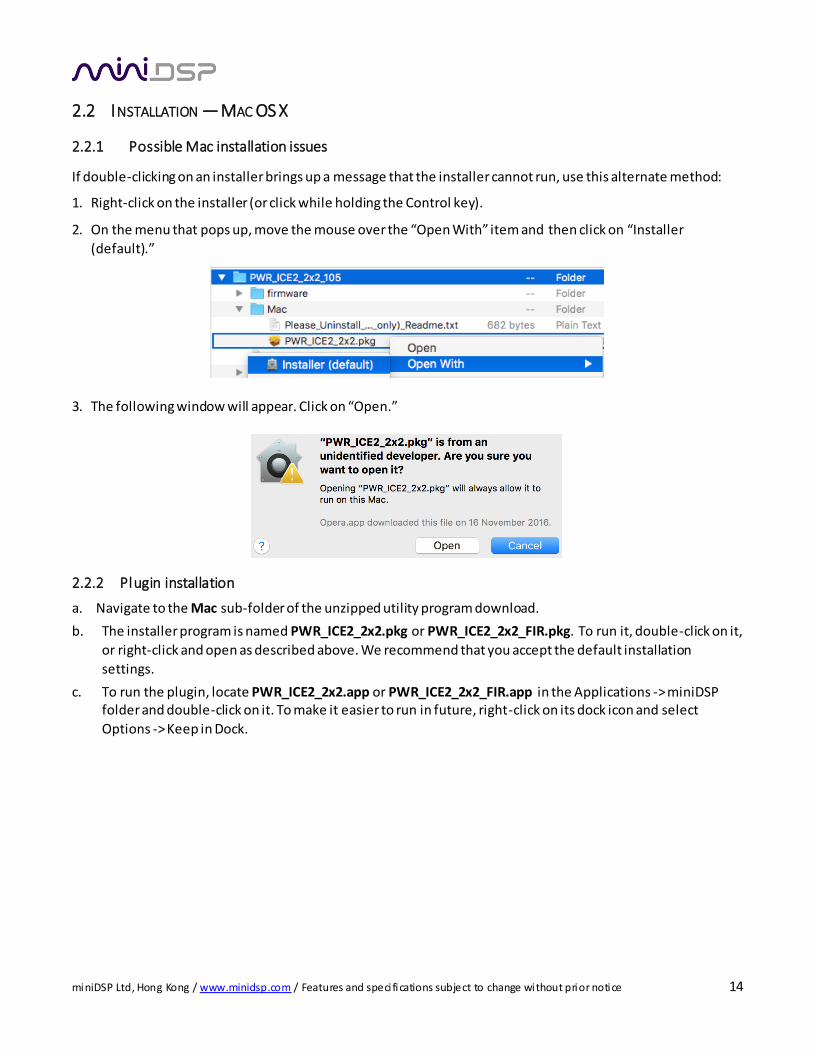
If double-clicking on an installer brings up a message that the installer cannot run, use this alternate method:
1. Right-click on the installer (or click while holding the Control key).
2. On the menu that pops up, move the mouse over the “Open With” item and then click on “Installer
(default).”
3. The following window will appear. Click on “Open.”
2.2.2 Plugin installation
a. Navigate to the Mac sub-folder of the unzipped utility program download.
b. The installer program is named PWR_ICE2_2x2.pkg or PWR_ICE2_2x2_FIR.pkg. To run it, double-click on it,
or right-click and open as described above. We recommend that you accept the default installation
settings.
c. To run the plugin, locate PWR_ICE2_2x2.app or PWR_ICE2_2x2_FIR.app in the Applications -> miniDSP folder and double-click on it. To make it easier to run in future, right-click on its dock icon and select
Options -> Keep in Dock.
miniDSP Ltd, Hong Kong / www.minidsp.com / Features and speci fications subject to change without prior notice 15
3 HARDWARE CONNECTIVITY
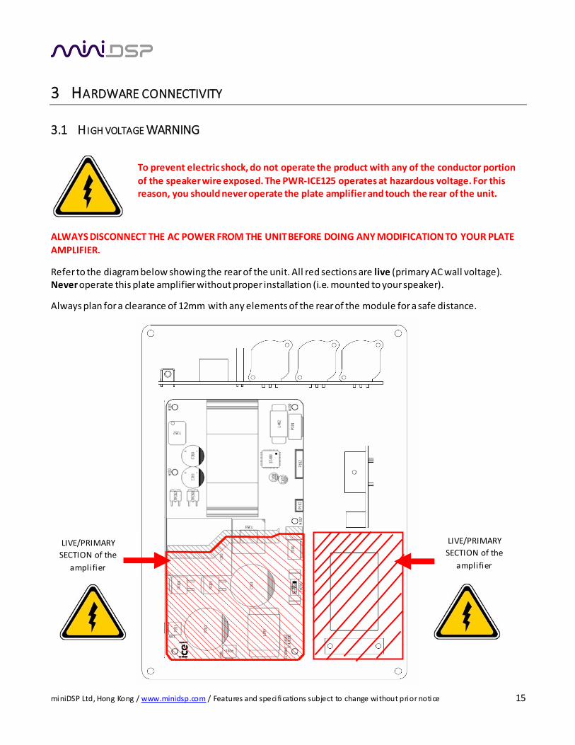
3.1 H IGH VOLTAGE WARNING
To prevent electric shock, do not operate the product with any of the conductor portion
of the speaker wire exposed. The PWR-ICE125 operates at hazardous voltage. For this reason, you should never operate the plate amplifier and touch the rear of the unit.
ALWAYS DISCONNECT THE AC POWER FROM THE UNIT BEFORE DOING ANY MODIFICATION TO YOUR PLATE
AMPLIFIER.
Refer to the diagram below showing the rear of the unit. All red sections are live (primary AC wall voltage). Never operate this plate amplifier without proper installation (i.e. mounted to your speaker).
Always plan for a clearance of 12mm with any elements of the rear of the module for a safe distance.
LIVE/PRIMARY
SECTION of the
amplifier
LIVE/PRIMARY
SECTION of the
amplifier
miniDSP Ltd, Hong Kong / www.minidsp.com / Features and speci fications subject to change without prior notice 16
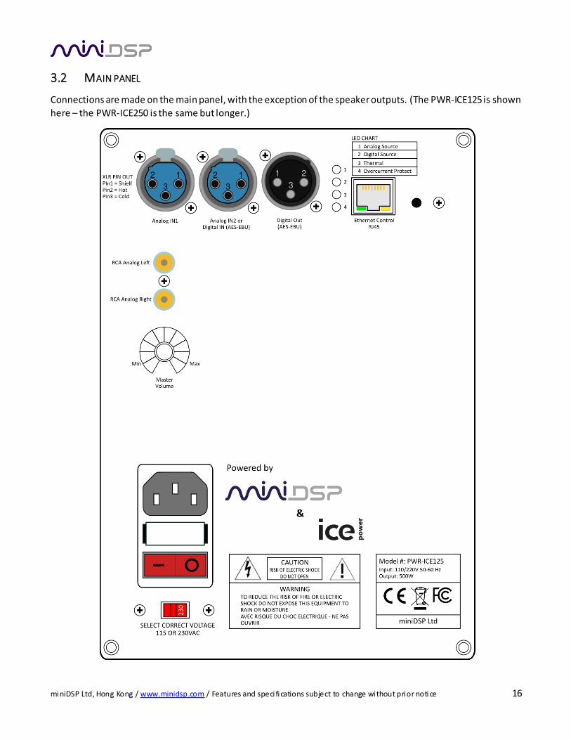
3.2 MAIN PANEL
Connections are made on the main panel, with the exception of the speaker outputs. (The PWR-ICE125 is shown
here – the PWR-ICE250 is the same but longer.)
miniDSP Ltd, Hong Kong / www.minidsp.com / Features and speci fications subject to change without prior notice 17
3.3 AC POWER
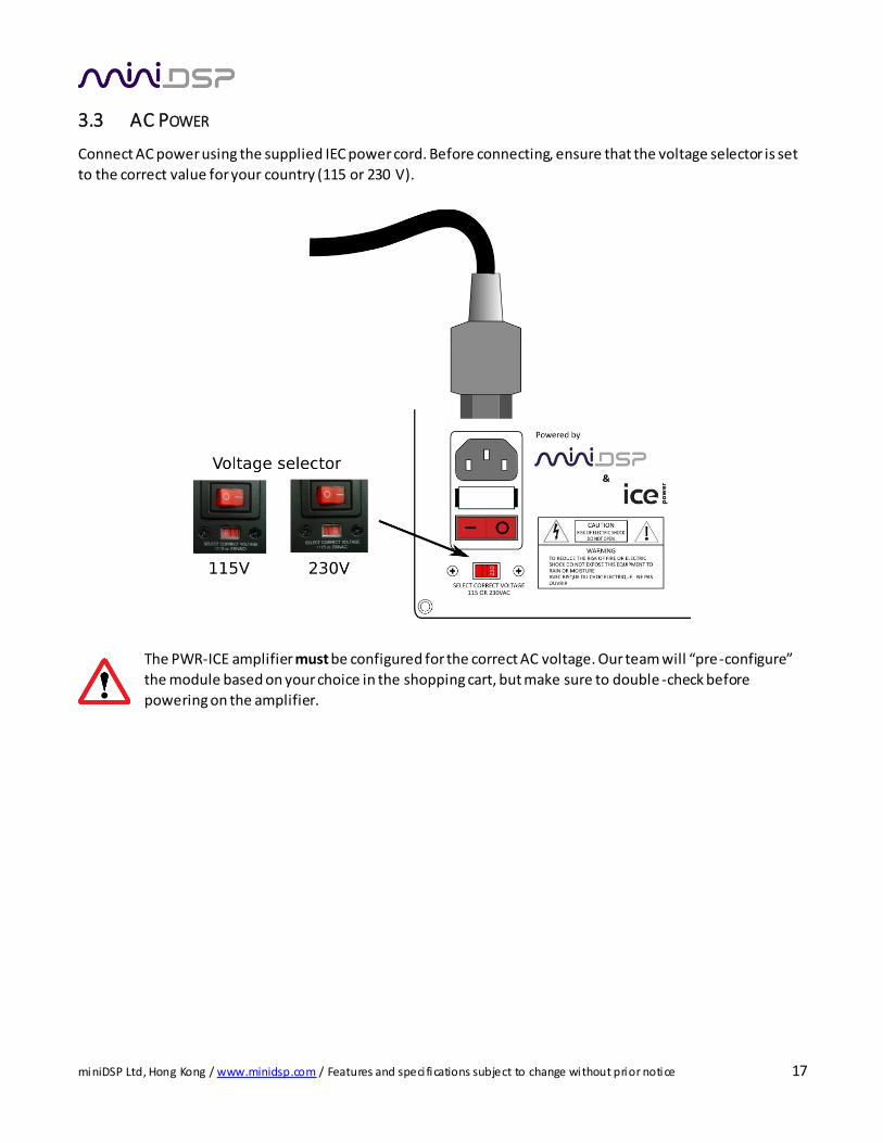
Connect AC power using the supplied IEC power cord. Before connecting, ensure that the voltage selector is set
to the correct value for your country (115 or 230 V).
The PWR-ICE amplifier must be configured for the correct AC voltage. Our team will “pre -configure”
the module based on your choice in the shopping cart, but make sure to double -check before
powering on the amplifier.
miniDSP Ltd, Hong Kong / www.minidsp.com / Features and speci fications subject to change without prior notice 18
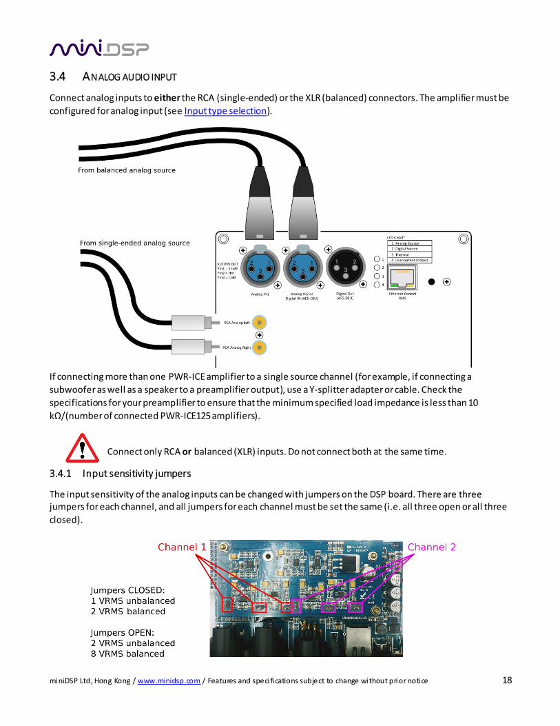
3.4 ANALOG AUDIO INPUT
Connect analog inputs to either the RCA (single-ended) or the XLR (balanced) connectors. The amplifier must be
configured for analog input (see Input type selection).
If connecting more than one PWR-ICE amplifier to a single source channel (for example, if connecting a
subwoofer as well as a speaker to a preamplifier output), use a Y-splitter adapter or cable. Check the
specifications for your preamplifier to ensure that the minimum specified load impedance is less than 10
kΩ/(number of connected PWR-ICE125 amplifiers).
Connect only RCA or balanced (XLR) inputs. Do not connect both at the same time.
3.4.1 Input sensitivity jumpers
The input sensitivity of the analog inputs can be changed with jumpers on the DSP board. There are three jumpers for each channel, and all jumpers for each channel must be set the same (i.e. all three open or all three
closed).
miniDSP Ltd, Hong Kong / www.minidsp.com / Features and speci fications subject to change without prior notice 19
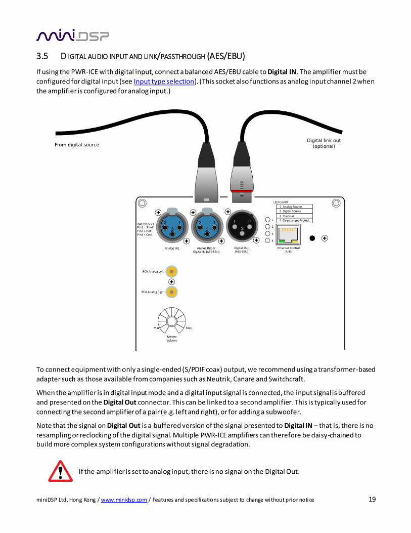
3.5 D IGITAL AUDIO INPUT AND LINK/PASSTHROUGH (AES/EBU)
If using the PWR-ICE with digital input, connect a balanced AES/EBU cable to Digital IN. The amplifier must be
configured for digital input (see Input type selection). (This socket also functions as analog input channel 2 when
the amplifier is configured for analog input.)
To connect equipment with only a single-ended (S/PDIF coax) output, we recommend using a transformer-based
adapter such as those available from companies such as Neutrik, Canare and Switchcraft.
When the amplifier is in digital input mode and a digital input signal is connected, the input signal is buffered
and presented on the Digital Out connector. This can be linked to a second amplifier. This is typically used for
connecting the second amplifier of a pair (e.g. left and right), or for adding a subwoofer.
Note that the signal on Digital Out is a buffered version of the signal presented to Digital IN – that is, there is no
resampling or reclocking of the digital signal. Multiple PWR-ICE amplifiers can therefore be daisy-chained to build more complex system configurations without signal degradation.
If the amplifier is set to analog input, there is no signal on the Digital Out.
miniDSP Ltd, Hong Kong / www.minidsp.com / Features and speci fications subject to change without prior notice 20
3.6 ETHERNET
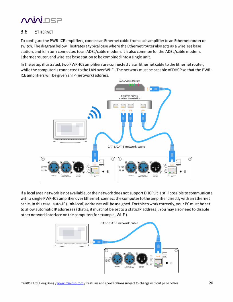
To configure the PWR-ICE amplifiers, connect an Ethernet cable from each amplifier to an Ethernet router or
switch. The diagram below illustrates a typical case where the Ethernet router also acts as a wireless base
station, and is in turn connected to an ADSL/cable modem. It is also common for the ADSL/cable modem,
Ethernet router, and wireless base station to be combined into a single unit.
In the setup illustrated, two PWR-ICE amplifiers are connected via an Ethernet cable to the Ethernet router,
while the computer is connected to the LAN over Wi-Fi. The network must be capable of DHCP so that the PWR-
ICE amplifiers will be given an IP (network) address.
If a local area network is not available, or the network does not support DHCP, it is still possible to communicate
with a single PWR-ICE amplifier over Ethernet: connect the computer to the amplifier directly with an Ethernet
cable. In this case, auto-IP (link-local) addresses will be assigned. For this to work correctly, your PC must be set
to allow automatic IP addresses (that is, it must not be set to a static IP address). You may also need to disable
other network interface on the computer (for example, Wi-Fi).
miniDSP Ltd, Hong Kong / www.minidsp.com / Features and speci fications subject to change without prior notice 21
3.7 SPEAKER CONNECTIONS
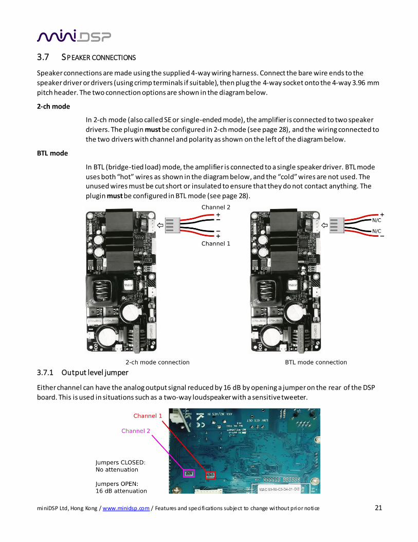
Speaker connections are made using the supplied 4-way wiring harness. Connect the bare wire ends to the
speaker driver or drivers (using crimp terminals if suitable), then plug the 4-way socket onto the 4-way 3.96 mm
pitch header. The two connection options are shown in the diagram below.
2-ch mode
In 2-ch mode (also called SE or single-ended mode), the amplifier is connected to two speaker
drivers. The plugin must be configured in 2-ch mode (see page 28), and the wiring connected to
the two drivers with channel and polarity as shown on the left of the diagram below.
BTL mode
In BTL (bridge-tied load) mode, the amplifier is connected to a single speaker driver. BTL mode
uses both “hot” wires as shown in the diagram below, and the “cold” wires are not used. The unused wires must be cut short or insulated to ensure that they do not contact anything. The
plugin must be configured in BTL mode (see page 28).
3.7.1 Output level jumper
Either channel can have the analog output signal reduced by 16 dB by opening a jumper on the rear of the DSP
board. This is used in situations such as a two-way loudspeaker with a sensitive tweeter.
miniDSP Ltd, Hong Kong / www.minidsp.com / Features and speci fications subject to change without prior notice 22
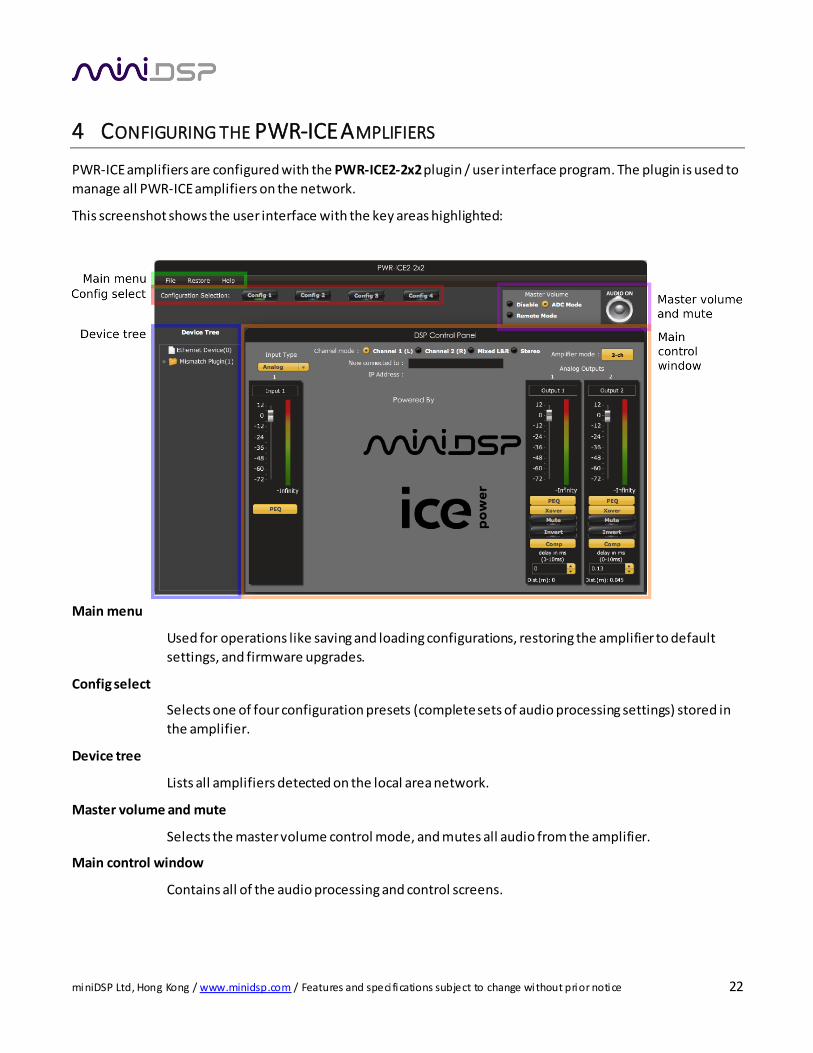
4 CONFIGURING THE PWR-ICE AMPLIFIERS
PWR-ICE amplifiers are configured with the PWR-ICE2-2x2 plugin / user interface program. The plugin is used to
manage all PWR-ICE amplifiers on the network.
This screenshot shows the user interface with the key areas highlighted:
Main menu
Used for operations like saving and loading configurations, restoring the amplifier to default
settings, and firmware upgrades.
Config select
Selects one of four configuration presets (complete sets of audio processing settings) stored in
the amplifier.
Device tree
Lists all amplifiers detected on the local area network.
Master volume and mute
Selects the master volume control mode, and mutes all audio from the amplifier.
Main control window
Contains all of the audio processing and control screens.
miniDSP Ltd, Hong Kong / www.minidsp.com / Features and speci fications subject to change without prior notice 23
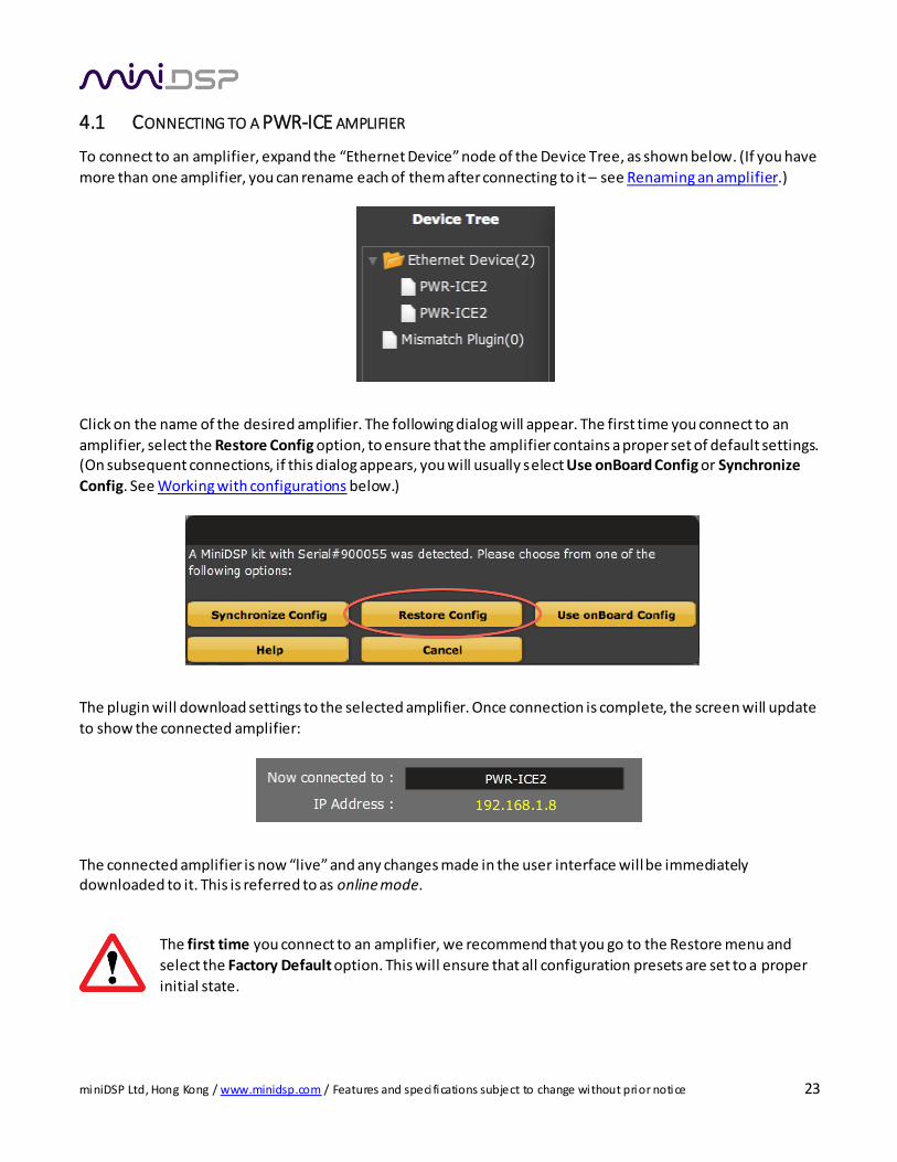
4.1 CONNECTING TO A PWR-ICE AMPLIFIER
To connect to an amplifier, expand the “Ethernet Device” node of the Device Tree, as shown below. (If you have
more than one amplifier, you can rename each of them after connecting to it – see Renaming an amplifier.)
Click on the name of the desired amplifier. The following dialog will appear. The first time you connect to an
amplifier, select the Restore Config option, to ensure that the amplifier contains a proper set of default settings. (On subsequent connections, if this dialog appears, you will usually select Use onBoard Config or Synchronize
Config. See Working with configurations below.)
The plugin will download settings to the selected amplifier. Once connection is complete, the screen will update
to show the connected amplifier:
The connected amplifier is now “live” and any changes made in the user interface will be immediately downloaded to it. This is referred to as online mode.
The first time you connect to an amplifier, we recommend that you go to the Restore menu and
select the Factory Default option. This will ensure that all configuration presets are set to a proper
initial state.
miniDSP Ltd, Hong Kong / www.minidsp.com / Features and speci fications subject to change without prior notice 24
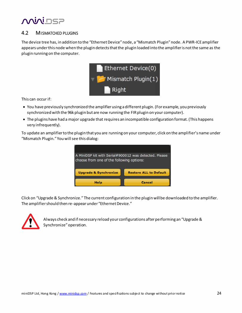
4.2 MISMATCHED PLUGINS
The device tree has, in addition to the “Ethernet Device” node, a “Mismatch Plugin” node. A PWR-ICE amplifier
appears under this node when the plugin detects that the plugin loaded into the amplifier is not the same as the
plugin running on the computer.
This can occur if:
You have previously synchronized the amplifier using a different plugin. (For example, you previously
synchronized with the 96k plugin but are now running the FIR plugin on your computer).
The plugins have had a major upgrade that requires an incompatible configuration format. (This happens
very infrequently).
To update an amplifier to the plugin that you are running on your computer, click on the amplifier’s name under
“Mismatch Plugin.” You will see this dialog:
Click on “Upgrade & Synchronize.” The current configuration in the plugin will be downloaded to the amplifier.
The amplifier should then re-appear under “Ethernet Device.”
Always check and if necessary reload your configurations after performing an “Upgrade &
Synchronize” operation.
miniDSP Ltd, Hong Kong / www.minidsp.com / Features and speci fications subject to change without prior notice 25
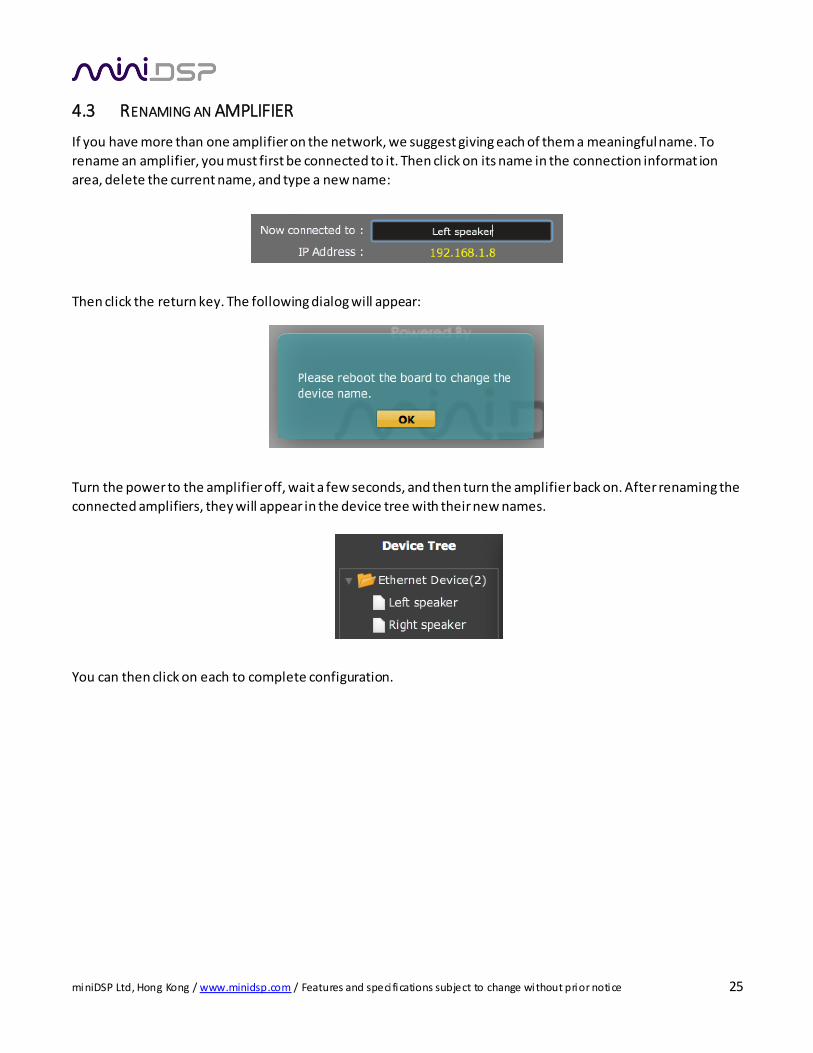
4.3 RENAMING AN AMPLIFIER
If you have more than one amplifier on the network, we suggest giving each of them a meaningful name. To
rename an amplifier, you must first be connected to it. Then click on its name in the connection informat ion
area, delete the current name, and type a new name:
Then click the return key. The following dialog will appear:
Turn the power to the amplifier off, wait a few seconds, and then turn the amplifier back on. After renaming the
connected amplifiers, they will appear in the device tree with their new names.
You can then click on each to complete configuration.
miniDSP Ltd, Hong Kong / www.minidsp.com / Features and speci fications subject to change without prior notice 26
4.4 CONFIGURATION PRESET SELECTION
The PWR-ICE amplifier has four configuration presets stored in memory. These are selected with the row of
buttons near the top of the screen. For more information on configurations, see Working with configurations.
4.5 MASTER VOLUME AND MUTE
The Master Mute button enables and disables both output channels:
The Master Volume selection buttons control the way in which master volume control is done.
Disable Master volume control is disabled.
ADC Mode The knob on the amplifier panel controls master volume.
Remote Mode The miniDSP Android app controls master volume.
4.6 INPUT TYPE SELECTION
The PWR-ICE amplifier accepts either analog or digital input. Use the dropdown selector to choose the appropriate type. The connected cabling and signals must match the selected input type.
miniDSP Ltd, Hong Kong / www.minidsp.com / Features and speci fications subject to change without prior notice 27
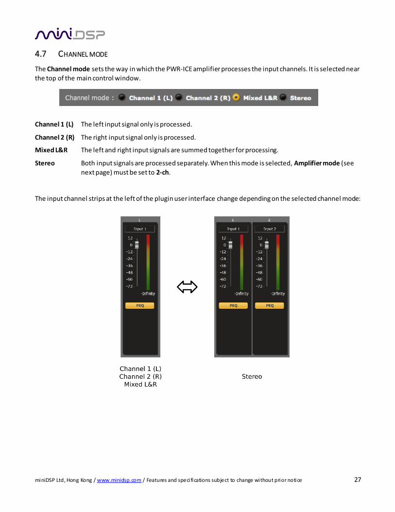
4.7 CHANNEL MODE
The Channel mode sets the way in which the PWR-ICE amplifier processes the input channels. It is selected near
the top of the main control window.
Channel 1 (L) The left input signal only is processed.
Channel 2 (R) The right input signal only is processed.
Mixed L&R The left and right input signals are summed together for processing.
Stereo Both input signals are processed separately. When this mode is selected, Amplifier mode (see
next page) must be set to 2-ch.
The input channel strips at the left of the plugin user interface change depending on the selected channel mode:
miniDSP Ltd, Hong Kong / www.minidsp.com / Features and speci fications subject to change without prior notice 28
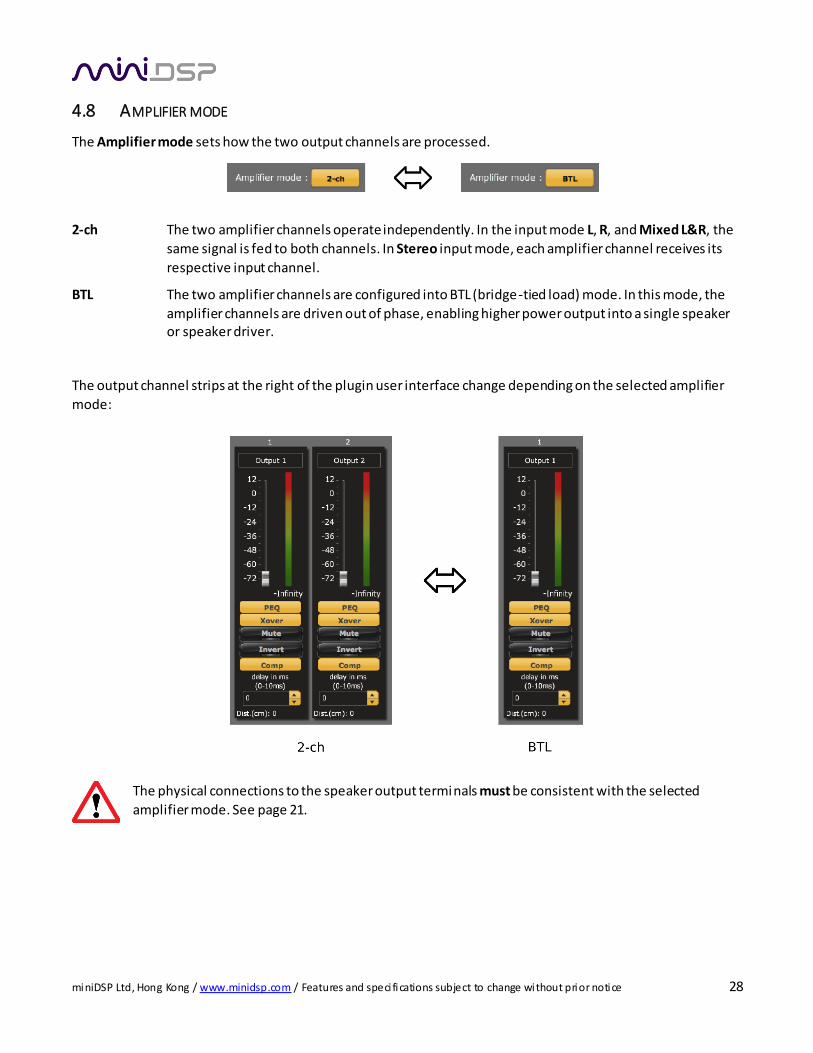
4.8 AMPLIFIER MODE
The Amplifier mode sets how the two output channels are processed.
2-ch The two amplifier channels operate independently. In the input mode L, R, and Mixed L&R, the
same signal is fed to both channels. In Stereo input mode, each amplifier channel receives its
respective input channel.
BTL The two amplifier channels are configured into BTL (bridge-tied load) mode. In this mode, the
amplifier channels are driven out of phase, enabling higher power output into a single speaker or speaker driver.
The output channel strips at the right of the plugin user interface change depending on the selected amplifier
mode:
The physical connections to the speaker output terminals must be consistent with the selected
amplifier mode. See page 21.
miniDSP Ltd, Hong Kong / www.minidsp.com / Features and speci fications subject to change without prior notice 29
4.9 MODE COMBINATIONS
The combination of Channel mode and Amplifier mode determine how the amplifier is used. Table 2
summarizes the various mode combinations and the most typical use.
Table 2. Channel mode, amplifier mode, and typical usage
Channel
mode
Amplifier
mode
Typical usage
L 2-ch Active crossover. Each output channel is connected to one speaker driver.
Typically, one channel is used for the tweeter and one for the woofer (or
woofers). A “FAST” configuration, where one channel is connected to a
fullrange driver and one to a woofer, is another common use for this configuration.
R 2-ch As above, but for the right speaker.
Mixed L&R 2-ch This is not a very common configuration, but it could be used in a situation
where a subwoofer contains two drivers, and each is driven by one amplifier
channel, with the signal taken from the sum of the left and right input channels.
Stereo 2-ch In this configuration, the PWR-ICE amplifier acts as a DSP-controlled stereo
amplifier. One use is when the PWR-ICE amplifier is used together with the
optional “back box” to create a standalone stereo amplifier. Another use can be
a pair of powered speakers, where a single PWR-ICE amplifier module is located
in one speaker box, and a speaker wire is taken across to a second speaker box
(that doesn’t contain an amplifier).
L BTL In this configuration, a single PWR-ICE amplifier acts as a high-power
“monoblock” amplifier for the left channel. Some possible uses are:
When multiple PWR-ICE amps are used in a single speaker, to power a
single driver (typically the woofer).
With the optional “back box,” as a standalone DSP-controlled high power monoblock amplifier.
R BTL As above, but for the right speaker.
Mixed L&R BTL This is the most common configuration when the PWR-ICE amplifier is used to
power a subwoofer. The whole amplifier drives a single subwoofer driver with
the sum of the left and right input channels.
miniDSP Ltd, Hong Kong / www.minidsp.com / Features and speci fications subject to change without prior notice 30
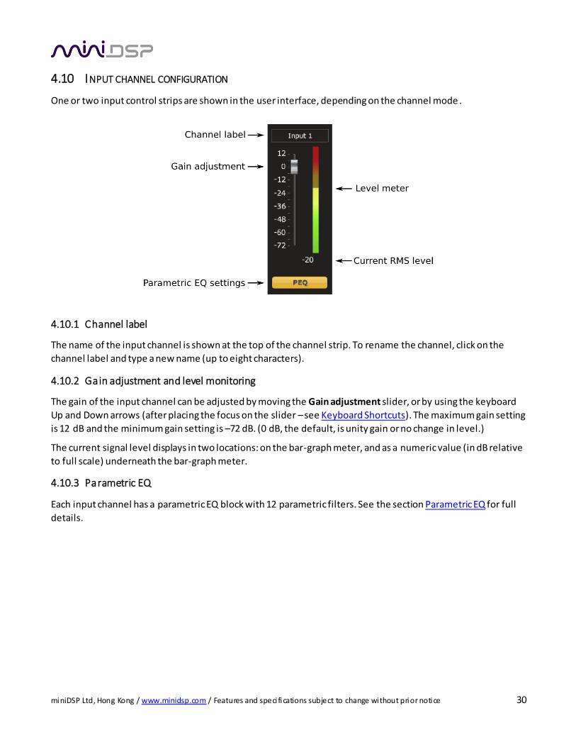
4.10 INPUT CHANNEL CONFIGURATION
One or two input control strips are shown in the user interface, depending on the channel mode .
4.10.1 Channel label
The name of the input channel is shown at the top of the channel strip. To rename the channel, click on the
channel label and type a new name (up to eight characters).
4.10.2 Gain adjustment and level monitoring
The gain of the input channel can be adjusted by moving the Gain adjustment slider, or by using the keyboard
Up and Down arrows (after placing the focus on the slider – see Keyboard Shortcuts). The maximum gain setting
is 12 dB and the minimum gain setting is –72 dB. (0 dB, the default, is unity gain or no change in level.)
The current signal level displays in two locations: on the bar-graph meter, and as a numeric value (in dB relative
to full scale) underneath the bar-graph meter.
4.10.3 Parametric EQ
Each input channel has a parametric EQ block with 12 parametric filters. See the section Parametric EQ for full
details.
miniDSP Ltd, Hong Kong / www.minidsp.com / Features and speci fications subject to change without prior notice 31
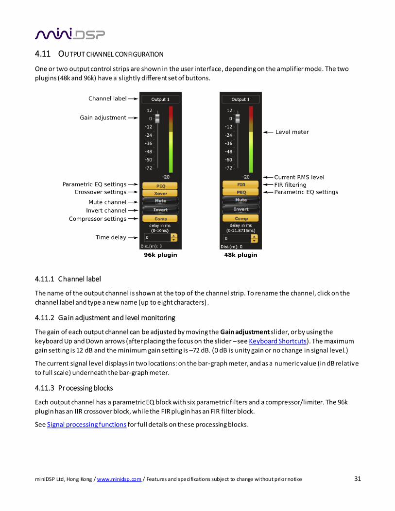
4.11 OUTPUT CHANNEL CONFIGURATION
One or two output control strips are shown in the user interface, depending on the amplifier mode. The two
plugins (48k and 96k) have a slightly different set of buttons.
4.11.1 Channel label
The name of the output channel is shown at the top of the channel strip. To rename the channel, click on the
channel label and type a new name (up to eight characters) .
4.11.2 Gain adjustment and level monitoring
The gain of each output channel can be adjusted by moving the Gain adjustment slider, or by using the
keyboard Up and Down arrows (after placing the focus on the slider – see Keyboard Shortcuts). The maximum
gain setting is 12 dB and the minimum gain setting is –72 dB. (0 dB is unity gain or no change in signal level.)
The current signal level displays in two locations: on the bar-graph meter, and as a numeric value (in dB relative
to full scale) underneath the bar-graph meter.
4.11.3 Processing blocks
Each output channel has a parametric EQ block with six parametric filters and a compressor/limiter. The 96k
plugin has an IIR crossover block, while the FIR plugin has an FIR filter block.
See Signal processing functions for full details on these processing blocks.
miniDSP Ltd, Hong Kong / www.minidsp.com / Features and speci fications subject to change without prior notice 32
4.11.4 Mute
This button mutes the output channel. This is helpful when testing and refining your configuration. (For
example, mute the tweeter to test the woofer, and vice versa.)
4.11.5 Invert
This button inverts the polarity of the output channel. In crossover applications, some slopes (e.g. 12 dB/octave)
typically require that one of the output channels be inverted. In subwoofer applications, this can be helpful to
improve integration with the main speakers.
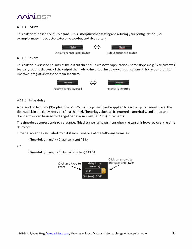
4.11.6 Time delay
A delay of up to 10 ms (96k plugin) or 21.875 ms (FIR plugin) can be applied to each output channel. To set the
delay, click in the delay entry box for a channel. The delay value can be entered numerically, and the up and
down arrows can be used to change the delay in small (0.02 ms) increments.
The time delay corresponds to a distance. This distance is shown in cm when the cursor is h overed over the time
delay box.
Time delay can be calculated from distance using one of the following formulae:
(Time delay in ms) = (Distance in cm) / 34.4
Or:
(Time delay in ms) = (Distance in inches) / 13.54
miniDSP Ltd, Hong Kong / www.minidsp.com / Features and speci fications subject to change without prior notice 33
4.12 WORKING WITH CONFIGURATIONS
The complete set of data that controls the audio processing of the PWR-ICE amplifier is called a configuration.
The PWR-ICE amplifier stores four configuration presets in its internal memory.
There are two modes of operation:
Offline mode
The plugin is running, but has not been connected to any amplifiers listed in the device tree. The
“Now connected to” field will be blank and any changes made in the plugin will not be
downloaded to any amplifiers. This is the state when the plugin is started. It can also occur in
cases where communication with the amplifier is lost, such as a network issue.
Online mode
The plugin is connected to an amplifier, which displays on the “Now connected to” field. Any
changes made to audio processing parameters in the plugin user interface are downloaded
immediately to the PWR-ICE amplifier. The effect of these changes will thus be audible as the
changes are made.
When the plugin goes into online mode, it checks to see whether its local state is consistent with the state of the
amplifier. If not, it brings up a dialog asking you to choose what to do. See Synchronization options.
4.12.1 Selecting a configuration preset
The current configuration is selected by the four buttons in the Configuration Sel ection area.
To switch to a different configuration preset, click on a different button. If the plugin is online, it first checks for
consistency between the local and remote states of the selected plugin. If they are consistent, the real-time
processing in the PWR-ICE amplifier will be updated to the newly selected configuration, and audio processing will then continue. If they are not consistent the dialog described in Synchronization options will appear.
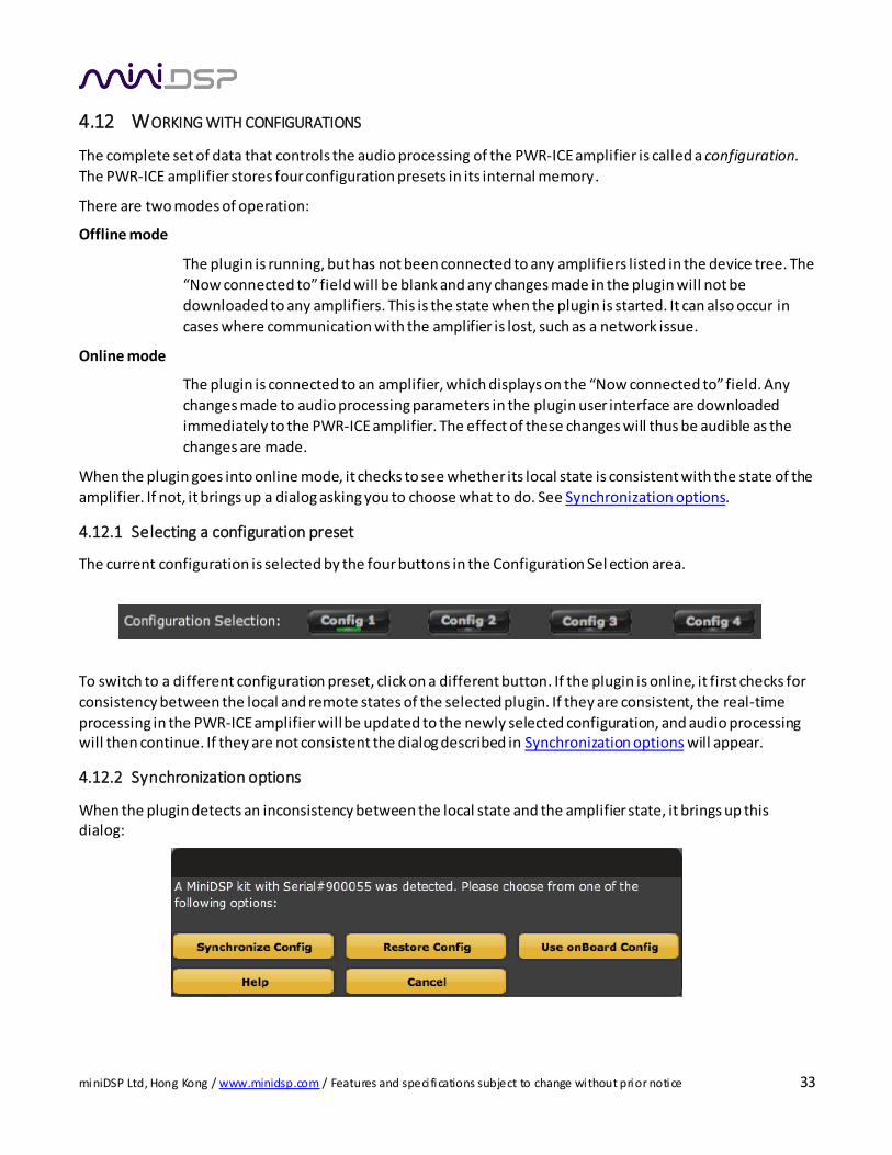
4.12.2 Synchronization options
When the plugin detects an inconsistency between the local state and the amplifier state, it brings up this dialog:
miniDSP Ltd, Hong Kong / www.minidsp.com / Features and speci fications subject to change without prior notice 34
The options are:
Synchronize Config
Download the currently selected configuration into the corresponding configuration preset of
the amplifier. The plugin will then be in online mode.
Restore Config
Restore the data in the currently selected configuration to the factory defaults, in both the plugin and the amplifier. The plugin will then be in online mode.
Use onBoard Config
Upload the configuration data from the amplifier to the plugin. The plugin will then be in online
mode.
Help This option brings up a help screen explaining the options.
Cancel This option cancels the attempt to synchronize the plugin with the amplifier. If the plugin was offline, it remains offline; if the plugin was online, then it remains online but does not switch
configurations.
4.12.3 Saving and loading configurations
Configurations can be saved to and loaded from files. Each configuration is stored in a separate file. It is strongly recommended that each configuration programmed into the PWR-ICE amplifier be saved to a file, to ensure that
the configuration is not lost if the PWR-ICE amplifier is inadvertently reset.
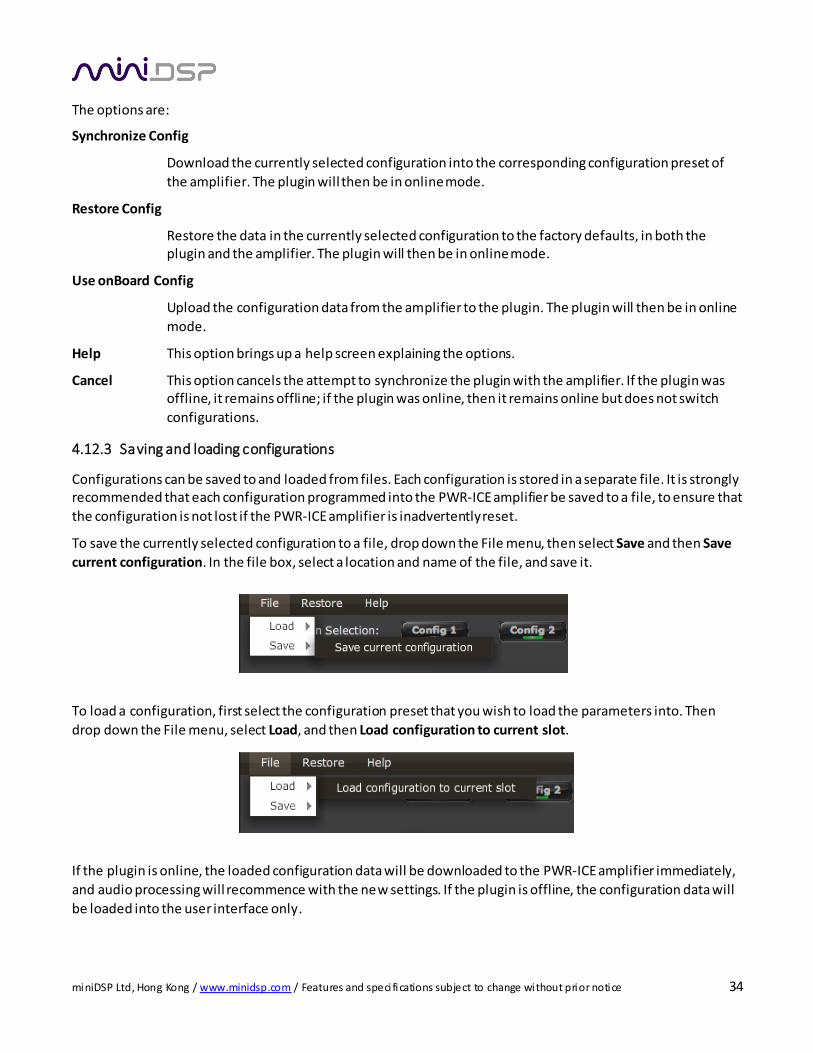
To save the currently selected configuration to a file, drop down the File menu, then select Save and then Save
current configuration. In the file box, select a location and name of the file, and save it.
To load a configuration, first select the configuration preset that you wish to load the parameters into. Then
drop down the File menu, select Load, and then Load configuration to current slot.
If the plugin is online, the loaded configuration data will be downloaded to the PWR-ICE amplifier immediately,
and audio processing will recommence with the new settings. If the plugin is offline, the configuration data will
be loaded into the user interface only.
miniDSP Ltd, Hong Kong / www.minidsp.com / Features and speci fications subject to change without prior notice 35
To copy a configuration from one preset to another, save the configuration to a file, then select a
different configuration preset and reload the file.
4.12.4 Restoring to defaults
Configurations can be reset to factory defaults from the Restore menu. There are two options:
Factory Default
Reset all four configuration presets to the factory default settings.
Current Configuration Only
Reset only the currently selected configuration preset to the factory default settings.
If the plugin is online, the default configuration data will be downloaded to the amplifier immediately.
Otherwise, the reset will take place in the user interface only.
Each configuration should be selected and checked/initialized prior to connecting loudspeakers to
the PWR-ICE amplifier.
4.13 KEYBOARD SHORTCUTS
The PWR-ICE amplifier user interface supports the use of the keyboard for many operations.
Tab The Tab key moves the focus from the current user interface element to the next. A light blue
surrounding box usually indicates the user interface element with the focus. For example, after changing the frequency of parametric filter, the Tab key moves the focus to the gain control, so
that the arrow keys can be used to change that channel’s gain. Shift-Tab moves the focus in the
opposite direction.
Up/down arrows
The up/down arrow keys adjust the value of many parameters:
Output channel gain
Crossover frequency and filter type
PEQ filter frequency, gain, and Q
Space The Space bar toggles buttons that have two states, such as Bypass, Invert, and Mute. If the
focus is on a control button such as PEQ, Xover, or Comp, the Space bar opens the relevant
control screen.
miniDSP Ltd, Hong Kong / www.minidsp.com / Features and speci fications subject to change without prior notice 36
5 SIGNAL PROCESSING FUNCTIONS
5.1 PARAMETRIC EQ
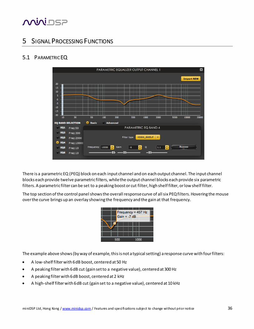
There is a parametric EQ (PEQ) block on each input channel and on each output channel. The input channel
blocks each provide twelve parametric filters, while the output channel blocks each provide six parametric
filters. A parametric filter can be set to a peaking boost or cut filter, high shelf filter, or low shelf filter.
The top section of the control panel shows the overall response curve of all six PEQ filters. Hovering the mouse over the curve brings up an overlay showing the frequency and the gain at that frequency.
The example above shows (by way of example, this is not a typical setting) a response curve with four filters:
A low-shelf filter with 6 dB boost, centered at 50 Hz
A peaking filter with 6 dB cut (gain set to a negative value), centered at 300 Hz
A peaking filter with 6 dB boost, centered at 2 kHz
A high-shelf filter with 6 dB cut (gain set to a negative value), centered at 10 kHz

miniDSP Ltd, Hong Kong / www.minidsp.com / Features and speci fications subject to change without prior notice 37
In detail, the parameters are as follows:
EQ band selection
Click on the radio buttons EQ1, EQ2, etc. to display the parameters for that filter.
Basic/Advanced
By default, each filter is in basic mode, and shows the controls described below. Advanced mode
enables custom biquad programming for almost infinite flexibility in filter implementation. This is described in Custom biquad programming.
Filter type
PEAK Create a dip or a peak in the frequency response.
LOW_SHELF Reduce or increase part of the frequency spectrum below a given frequency.
HIGH_SHELF Reduce or increase part of the frequency spectrum above a given frequency.
SUB_EQ Create a dip or a peak in the frequency response at low frequencies (10 to 50
Hz). This filter type is similar to PEAK but gives more accurate results for low
frequencies. Note that activating any SUB_EQ filter reduces the number of
available filters in that block by one.
Frequency
For the PEAK filter type, this is the center frequency of the peak or dip. For the HIGH_SHELF and LOW_SHELF filter types, this is the frequency at which the gain is half of the set value.
Gain
For the PEAK filter type, this is the gain in dB at the center frequency. For the HIGH_SHELF and
LOW_SHELF filter types, this is the gain in dB reached at high or low frequencies respectively. A
filter has no effect if its gain is set to 0. Gain can be adjusted in increments of 0.1 dB up to +/ - 16
dB.
Q
Q controls the “sharpness” of the filter. For the PEAK filter type, lower Q gives a shallower peak
or dip, while higher Q gives a narrower peak or dip. For the HIGH_SHELF and LOW_SHELF filter
types, Q controls how quickly the filter transitions from no gain to maximum gain.
Bypass
Clicking on the Bypass button disables that filter. (All other filters are still operational unless individually bypassed.)
Import REW
This button selects a file exported from Room EQ Wizard’s automatic equalization function. For
more information, see the section Custom biquad programming and the app note Auto-EQ
tuning with REW.
miniDSP Ltd, Hong Kong / www.minidsp.com / Features and speci fications subject to change without prior notice 38
5.2 CROSSOVER (96K PLUGIN ONLY)
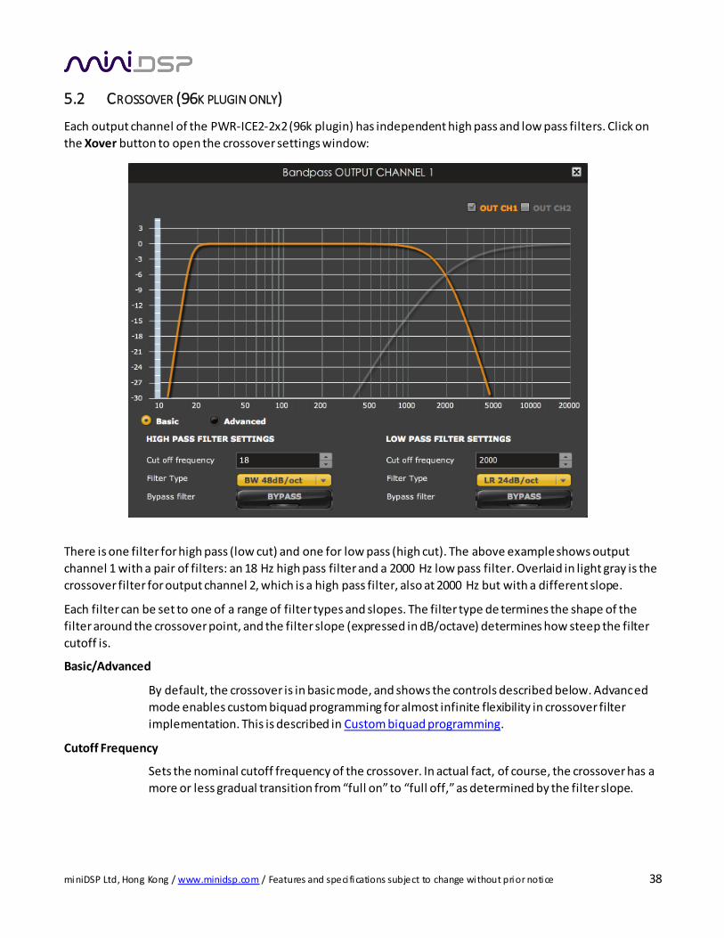
Each output channel of the PWR-ICE2-2x2 (96k plugin) has independent high pass and low pass filters. Click on
the Xover button to open the crossover settings window:
There is one filter for high pass (low cut) and one for low pass (high cut). The above example shows output
channel 1 with a pair of filters: an 18 Hz high pass filter and a 2000 Hz low pass filter. Overlaid in light gray is the
crossover filter for output channel 2, which is a high pass filter, also at 2000 Hz but with a different slope.
Each filter can be set to one of a range of filter types and slopes. The filter type de termines the shape of the
filter around the crossover point, and the filter slope (expressed in dB/octave) determines how steep the filter
cutoff is.
Basic/Advanced
By default, the crossover is in basic mode, and shows the controls described below. Advanced
mode enables custom biquad programming for almost infinite flexibility in crossover filter
implementation. This is described in Custom biquad programming.
Cutoff Frequency
Sets the nominal cutoff frequency of the crossover. In actual fact, of course, the crossover has a
more or less gradual transition from “full on” to “full off,” as determined by the filter slope.
miniDSP Ltd, Hong Kong / www.minidsp.com / Features and speci fications subject to change without prior notice 39
Filter type
Selects the type and slope of the filter. The steeper the slope, the more quick ly frequencies
above or below the cutoff frequency are attenuated. There are three types of filter:
Butterworth (BW)
Available in 6, 12, 18, 24, 30, 36, 42, and 48 dB/octave, Butterworth crossover
filters are 3 dB down at the cutoff frequency.
Linkwitz-Riley (LR)
Available in 12, 24, and 48 dB/octave, Linkwitz-Riley crossover filters are 6 dB
down at the cutoff frequency.
Bessel
Available in 12 dB/octave only, a Bessel filter gives a more gradual roll -off
through the crossover region.
Bypass
Clicking on the Bypass button disables that high pass or low pass filter. (The other filter is still
active, unless specifically bypassed also.)
5.3 FIR FILTERING AND DESIGN (FIR PLUGIN ONLY)
Each output channel of the PWR-ICE2-2x2-FIR (FIR plugin) has an FIR filter that can be used for driver correction
and crossover. The filter banks are asymmetrical (they have different numbers of taps – see next page). FIR
filtering allows construction of complex arbitrary equalization and crossover filters with independent control of
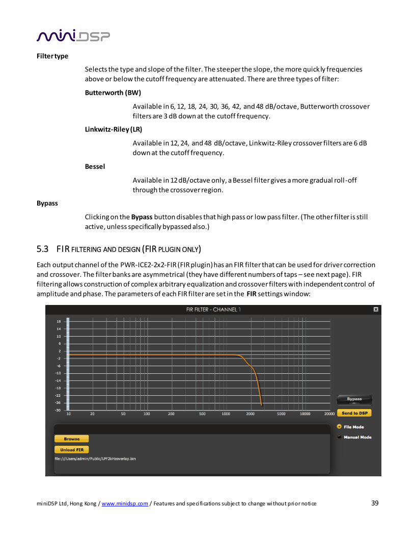
amplitude and phase. The parameters of each FIR filter are set in the FIR settings window:
miniDSP Ltd, Hong Kong / www.minidsp.com / Features and speci fications subject to change without prior notice 40
Browse Opens a filter browser to select a file containing FIR filter coefficients. (See FIR filter file format
below).
Unload FIR Deletes the currently loaded filter coefficients from the plugin (all coefficients are set to zero).
Bypass Disables the FIR filter. The filter is disabled when the button is "lit."
Send to DSP Writes the current set of filter coefficients into the DSP memory.
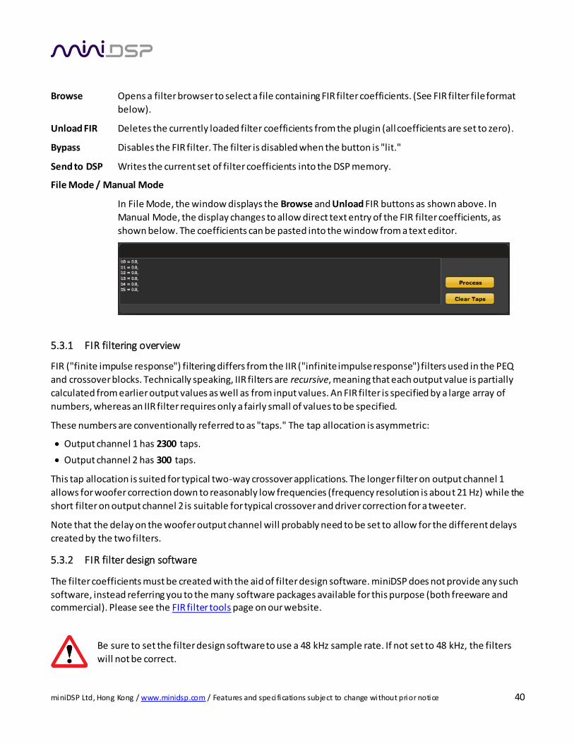
File Mode / Manual Mode
In File Mode, the window displays the Browse and Unload FIR buttons as shown above. In
Manual Mode, the display changes to allow direct text entry of the FIR filter coefficients, as
shown below. The coefficients can be pasted into the window from a text editor.
5.3.1 FIR filtering overview
FIR ("finite impulse response") filtering differs from the IIR ("infinite impulse response") filters used in the PEQ
and crossover blocks. Technically speaking, IIR filters are recursive, meaning that each output value is partially
calculated from earlier output values as well as from input values. An FIR filter is specified by a large array of
numbers, whereas an IIR filter requires only a fairly small of values to be specified.
These numbers are conventionally referred to as "taps." The tap allocation is asymmetric:
Output channel 1 has 2300 taps.
Output channel 2 has 300 taps.
This tap allocation is suited for typical two-way crossover applications. The longer filter on output channel 1
allows for woofer correction down to reasonably low frequencies (frequency resolution is about 21 Hz) while the
short filter on output channel 2 is suitable for typical crossover and driver correction for a tweeter.
Note that the delay on the woofer output channel will probably need to be set to allow for the different delays
created by the two filters.
5.3.2 FIR filter design software
The filter coefficients must be created with the aid of filter design software. miniDSP does not provide any such
software, instead referring you to the many software packages available for this purpose (both freeware and commercial). Please see the FIR filter tools page on our website.
Be sure to set the filter design software to use a 48 kHz sample rate. If not set to 48 kHz, the filters
will not be correct.
miniDSP Ltd, Hong Kong / www.minidsp.com / Features and speci fications subject to change without prior notice 41
5.3.3 Fi lter file format
The filter coefficient file loaded in File Mode uses IEEE 754 single-precision binary floating-point format. The number of entries in the file must not exceed the allocated number of taps.
In Manual Mode, the coefficients must be plain text in this format:
b0 = 1,
b1 = -1,
b2 = 0.5,
b3 = -0.5,
b4 = 0.2,
b5 = 1,
5.3.4 Loading filter coefficients
In File Mode:
a. Click Browse, navigate to the file containing the filter coefficients, and open it. A dialog will appear
confirming the number of coefficients loaded.
b. Confirm that the response curve is as you expect.
c. Press Send to DSP. This will write the coefficients into the DSP's memory.
d. To clear the filter coefficients, click Unload FIR and then Send to DSP.
In Manual Mode:
a. Cut and paste the coefficients from the text output of the design program.
b. Press the Process button.
c. Confirm that the frequency response graph is as you expect.
d. Press Send to DSP. This will write the coefficients into the DSP's memory.
e. To clear the filter coefficients, click Clear Taps and then Send to DSP.
If, after selecting a filter file or setting coefficients, the frequency
response graph does not change as expected, make sure that the filter is not bypassed.
If you clear the filter taps, make sure that you also bypass the
filter, otherwise there will be no audio through that channel.
miniDSP Ltd, Hong Kong / www.minidsp.com / Features and speci fications subject to change without prior notice 42
5.4 CUSTOM BIQUAD PROGRAMMING
Custom biquad programming is available in the parametric EQ and crossover blocks. Its purpose is to allow you
to directly provide the low-level parameters aka biquad coefficients that control the digital filters, thus providing
an almost infinite degree of flexibility.
For example, you can create hybrid crossovers with more than one cutoff frequency, create crossover filter types beyond those provided in the easy-to-use “basic” interface, implement a Linkwitz transform, or mix
crossover and filtering biquads in the same block.
5.4.1 What’s a “biquad?
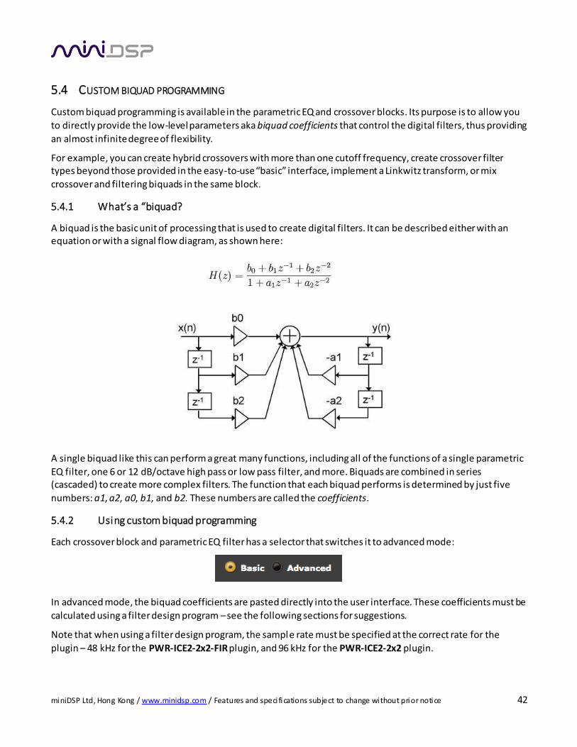
A biquad is the basic unit of processing that is used to create digital filters. It can be described either with an equation or with a signal flow diagram, as shown here:
A single biquad like this can perform a great many functions, including all of the functions of a single parametric
EQ filter, one 6 or 12 dB/octave high pass or low pass filter, and more. Biquads are combined in series (cascaded) to create more complex filters. The function that each biquad performs is determined by just five
numbers: a1, a2, a0, b1, and b2. These numbers are called the coefficients.
5.4.2 Using custom biquad programming
Each crossover block and parametric EQ filter has a selector that switches it to advanced mode:
In advanced mode, the biquad coefficients are pasted directly into the user interface. These coefficients must be
calculated using a filter design program – see the following sections for suggestions.
Note that when using a filter design program, the sample rate must be specified at the correct rate for the
plugin – 48 kHz for the PWR-ICE2-2x2-FIR plugin, and 96 kHz for the PWR-ICE2-2x2 plugin.

miniDSP Ltd, Hong Kong / www.minidsp.com / Features and speci fications subject to change without prior notice 43
Parametric EQ advanced mode
In the parametric EQ blocks, advanced mode allows each individual filter to be speci fied by its
coefficients. After pasting in the biquad coefficients, click on the Process button for them to take
effect.
Parametric EQ file import
Six filters can be set at once by importing a coefficient file from Room EQ Wizard (REW). See
Room EQ Wizard below.
Crossover advanced mode (96k plugin only)
Each Crossover block has eight biquads. In Basic mode, this provides high pass and low pass
filters of up to 48 dB/octave. In Advanced mode, all eight biquads need to be specified. After
pasting in the biquad coefficients, click on the Process button for them to take effect.
5.4.3 Biquad calculation spreadsheet
The community-developed biquad calculation spreadsheet allows more filter types to be calculated, including
notch filters, Linkwitz transforms, and filters with arbitrary Q-factor. Access this spreadsheet here (requires
Microsoft Excel):
http://www.minidsp.com/images/fbfiles/files/All_digital_coefs_v1-20101026.zip
In the spreadsheet, each page has an Fs parameter. Be sure to set this to the correct sample rate for the plugin
you are using – either 48 kHz or 96 kHz.
5.4.4 Room EQ Wizard (REW)
Room EQ Wizard is a free acoustic measurement and analysis tool, available for Windows, Mac and Linux
platforms. It includes the ability to automatically generate a bank of parametric EQ biquads based on a
miniDSP Ltd, Hong Kong / www.minidsp.com / Features and speci fications subject to change without prior notice 44
measurement. These coefficients can be saved to a file from REW and loaded directly into a PEQ bank in a miniDSP plugin. Room EQ Wizard can be downloaded here:
http://www.roomeqwizard.com/#downloads
For guidance on using this feature, please refer to the app note Auto EQ with REW. For the Equalizer setting,
choose “MiniDSP” for the FIR plugin, and “MiniDSP-96k” for the 96k plugin.
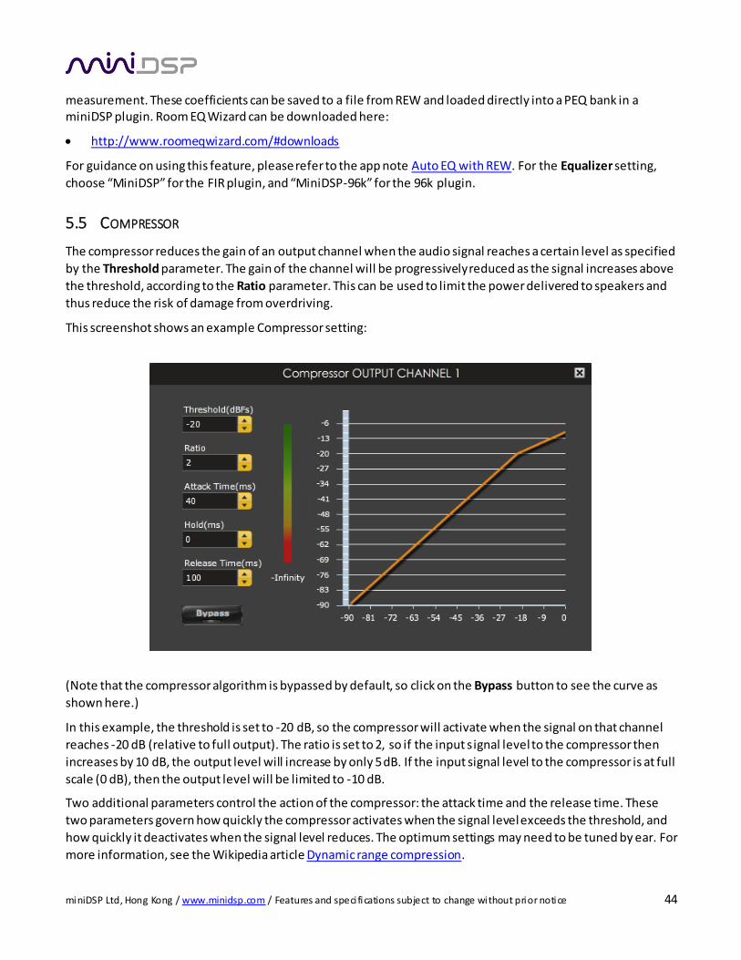
5.5 COMPRESSOR
The compressor reduces the gain of an output channel when the audio signal reaches a certain level as specified
by the Threshold parameter. The gain of the channel will be progressively reduced as the signal increases above
the threshold, according to the Ratio parameter. This can be used to limit the power delivered to speakers and
thus reduce the risk of damage from overdriving.
This screenshot shows an example Compressor setting:
(Note that the compressor algorithm is bypassed by default, so click on the Bypass button to see the curve as
shown here.)
In this example, the threshold is set to -20 dB, so the compressor will activate when the signal on that channel
reaches -20 dB (relative to full output). The ratio is set to 2, so if the input signal level to the compressor then
increases by 10 dB, the output level will increase by only 5 dB. If the input signal level to the compressor is at full
scale (0 dB), then the output level will be limited to -10 dB.
Two additional parameters control the action of the compressor: the attack time and the release time. These
two parameters govern how quickly the compressor activates when the signal level exceeds the threshold, and
how quickly it deactivates when the signal level reduces. The optimum settings may need to be tuned by ear. For
more information, see the Wikipedia article Dynamic range compression.
miniDSP Ltd, Hong Kong / www.minidsp.com / Features and speci fications subject to change without prior notice 45
6 ADDITIONAL INFORMATION
6.1 KEY SPECIFICATIONS
6.1.1 General
Analog inputs Stereo RCA, 1V or 2V RMS maximum input (jumper selectable)
Stereo balanced (XLR), 2V or 8V RMS maximum input (jumper selectable)
Digital input AES/EBU, sample rates up to 216 kHz
Resolution 24-bit, 96 kHz
Protection features Overcurrent and thermal overload protection
Supply voltage 85 to 132 VAC (switch set to “115V”)
170 to 264 VAC (switch set to “230V”)
6.1.2 PWR-ICE125
Power output, SE/2-ch
mode, RL = 4Ω 1
120 W/channel (230V/50Hz AC)
105 W/channel (115V/50Hz AC)
Power output, BTL mode,
RL = 4Ω 2
450 W (230V/50Hz AC)
370 W (115V/50Hz AC)
Dimensions (H x W x D) 153 x 216 x 77 mm
6.1.3 PWR-ICE250
Power output, SE/2-ch
mode, RL = 4Ω 1
230 W/channel (230V/50Hz AC)
200 W/channel (115V/50Hz AC)
Power output, BTL mode, RL = 8Ω 2
500 W (230V/50Hz AC)
420 W (115V/50Hz AC)
Dimensions (H x W x D) 153 x 267.5 x 77 mm
1. 1% THD+N20Hz < f < 20kHz, both channels driven. (AES17 measurement fi lter). Specification provided by ICEpower.
See ICEpower datasheets for 125ASX2 and 250ASX2 for full specifications.
2. 1% THD+N20Hz < f < 20kHz. (AES17 measurement fi lter). Specification provided by ICEpower. See ICEpower datasheets for 125ASX2 and 250ASX2 for full specifications.
miniDSP Ltd, Hong Kong / www.minidsp.com / Features and speci fications subject to change without prior notice 46
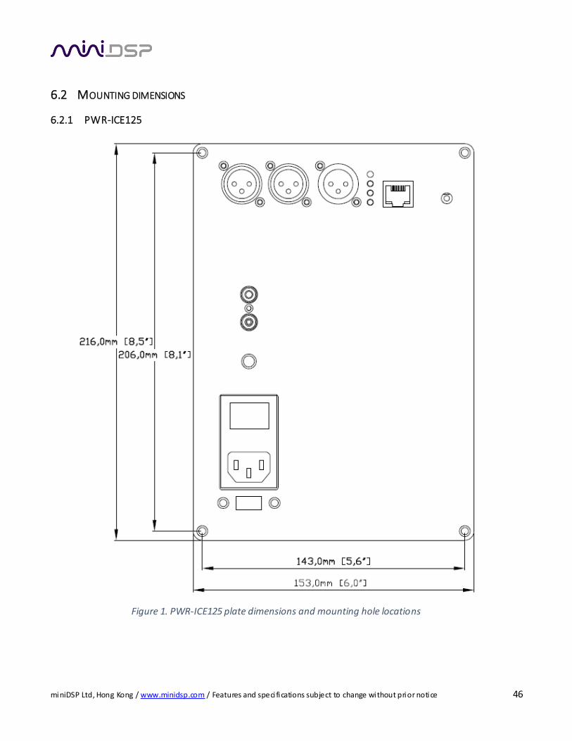
6.2 MOUNTING DIMENSIONS
6.2.1 PWR-ICE125
Figure 1. PWR-ICE125 plate dimensions and mounting hole locations
miniDSP Ltd, Hong Kong / www.minidsp.com / Features and speci fications subject to change without prior notice 47
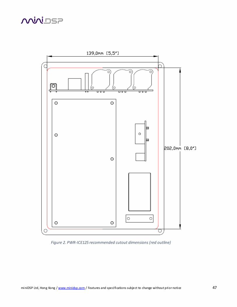
Figure 2. PWR-ICE125 recommended cutout dimensions (red outline)
miniDSP Ltd, Hong Kong / www.minidsp.com / Features and speci fications subject to change without prior notice 48
6.2.2 PWR-ICE250
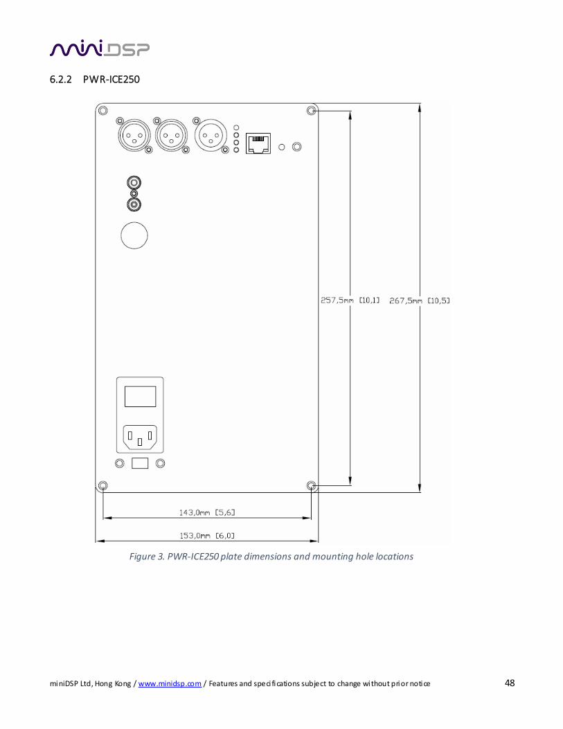
Figure 3. PWR-ICE250 plate dimensions and mounting hole locations
miniDSP Ltd, Hong Kong / www.minidsp.com / Features and speci fications subject to change without prior notice 49
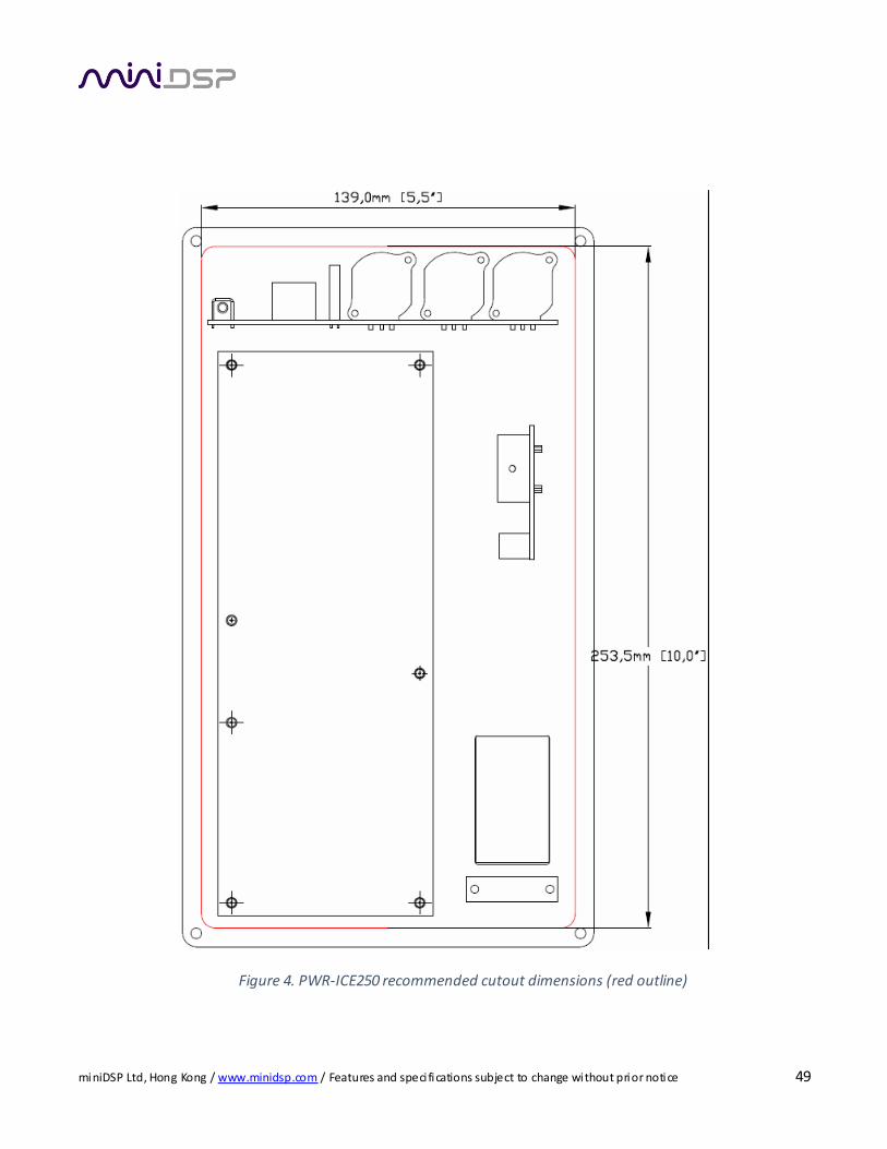
Figure 4. PWR-ICE250 recommended cutout dimensions (red outline)

miniDSP Ltd, Hong Kong / www.minidsp.com / Features and speci fications subject to change without prior notice 50
6.2.3 Additional mounting considerations
Please note the following points:
1. The minimum depth from the front plate is 77mm (3 inches).
2. The plate is not sealed or airtight. Mounting directly into a sealed loudspeaker enclosure is therefore not recommended. Instead, a sub-enclosure should be used.
3. Adequate space and airflow must be allowed around the amplifier to aid cooling. If a separate sub-
enclosure is used, ensure that air can flow around the amplifier module.
4. It must not be possible to touch any exposed high voltage parts of the amplifier while it is powered on.
(For example, if a subwoofer has a sufficiently large port, ensure that it is not possible to insert a hand
and touch the high voltage parts.) See page 15 for locations of high-voltage parts.
miniDSP Ltd, Hong Kong / www.minidsp.com / Features and speci fications subject to change without prior notice 51
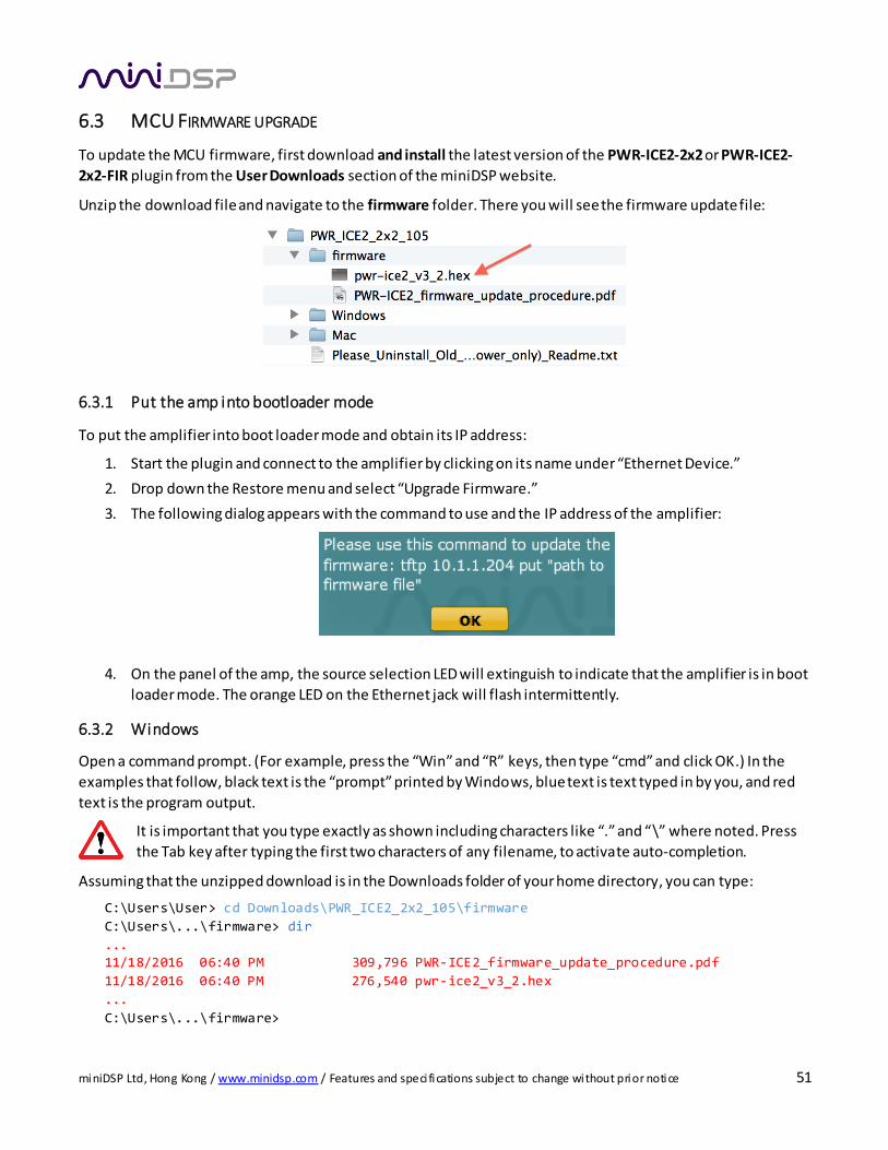
6.3 MCU FIRMWARE UPGRADE
To update the MCU firmware, first download and install the latest version of the PWR-ICE2-2x2 or PWR-ICE2-
2x2-FIR plugin from the User Downloads section of the miniDSP website.
Unzip the download file and navigate to the firmware folder. There you will see the firmware update file:
6.3.1 Put the amp into bootloader mode
To put the amplifier into boot loader mode and obtain its IP address:
1. Start the plugin and connect to the amplifier by clicking on its name under “Ethernet Device.”
2. Drop down the Restore menu and select “Upgrade Firmware.”
3. The following dialog appears with the command to use and the IP address of the amplifier:
4. On the panel of the amp, the source selection LED will extinguish to indicate that the amplifier is in boot
loader mode. The orange LED on the Ethernet jack will flash intermittently.
6.3.2 Windows
Open a command prompt. (For example, press the “Win” and “R” keys, then type “cmd” and click OK.) In the
examples that follow, black text is the “prompt” printed by Windows, blue text is text typed in by you, and red
text is the program output.
It is important that you type exactly as shown including characters like “.” and “\” where noted. Press
the Tab key after typing the first two characters of any filename, to activate auto-completion.
Assuming that the unzipped download is in the Downloads folder of your home directory, you can type:
C:\Users\User> cd Downloads\PWR_ICE2_2x2_105\firmware
C:\Users\...\firmware> dir
... 11/18/2016 06:40 PM 309,796 PWR-ICE2_firmware_update_procedure.pdf
11/18/2016 06:40 PM 276,540 pwr-ice2_v3_2.hex
...
C:\Users\...\firmware>
miniDSP Ltd, Hong Kong / www.minidsp.com / Features and speci fications subject to change without prior notice 52
(The version number “105” may be different.)
You can see in the above list the name of the firmware file, pwr-ice2_v3_2.hex (the version number “v3_2” may
change). Now type the following sequence of commands. Instead of “192.168.1.15” type the number revealed in
the instructions above, and be sure also to type the correct firmware file name:
C:\Users\...\firmware> tftp 192.168.1.15 put pwr-ice2_v3_2.hex
Transfer successful, 2765400 bytes in 12 second(s), 23045 bytes/s
C:\Users\...\firmware>
While the firmware is downloading, the orange LED of the Ethernet jack will light. The download should take
about ten to twenty seconds.
Power off the amplifier, wait a few seconds, and then power it on again. You can now proceed to use it as
normal.
6.3.3 Mac
To load firmware using Mac OS X requires that you use the Terminal program (located in the
Applications/Utilities folder). In the examples that follow, black text is the “prompt” printed by Terminal, blue
text is text typed in by you, and red text is the program output.
It is important that you type exactly as shown including characters like “.” and “/” where noted. Press the Tab key after typing the first two characters of any filename, to activate auto-completion.
Assuming that the unzipped download is in the Downloads folder on your Mac, you can type:
mac:~ me$ cd Downloads/PWR_ICE2_2x2_105/firmware/
mac:firmware me $ ls
PWR-ICE2_firmware_update_procedure.pdf
pwr-ice2_v3_2.hex mac: firmware me $
(The version number “105” may be different.)
You can see in the above list the name of the firmware file, pwr-ice2_v3_2.hex (the version number “v3_2” may
change). Now type the following sequence of commands. Instead of “192.168.1.15” type the number revealed in
the generic instructions above, and be sure also to type the correct firmware file name:
mac:firmware me$ tftp 192.168.1.15 > binary
> rexmt 1
> timeout 60
> put pwr-ice2_v3_2.hex
Sent 276540 bytes in 15.8 seconds
> quit mac:firmware $
While the firmware is downloading, the orange LED of the Ethernet jack will light. The download should take
about ten to twenty seconds.
Power off the amplifier, wait a few seconds, and then power it on again. You can now proceed to use it as
normal.
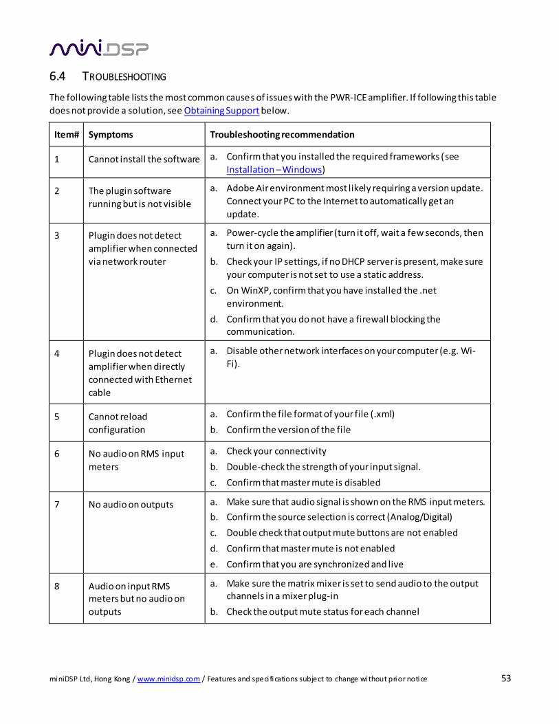
miniDSP Ltd, Hong Kong / www.minidsp.com / Features and speci fications subject to change without prior notice 53
6.4 TROUBLESHOOTING
The following table lists the most common causes of issues with the PWR-ICE amplifier. If following this table
does not provide a solution, see Obtaining Support below.
Item# Symptoms Troubleshooting recommendation
1 Cannot install the software a. Confirm that you installed the required frameworks (see
Installation – Windows)
2 The plugin software
running but is not visible
a. Adobe Air environment most likely requiring a version update.
Connect your PC to the Internet to automatically get an
update.
3 Plugin does not detect
amplifier when connected
via network router
a. Power-cycle the amplifier (turn it off, wait a few seconds, then
turn it on again).
b. Check your IP settings, if no DHCP server is present, make sure
your computer is not set to use a static address.
c. On WinXP, confirm that you have installed the .net
environment.
d. Confirm that you do not have a firewall blocking the communication.
4 Plugin does not detect
amplifier when directly
connected with Ethernet
cable
a. Disable other network interfaces on your computer (e.g. Wi-
Fi).
5 Cannot reload
configuration
a. Confirm the file format of your file (.xml)
b. Confirm the version of the file
6 No audio on RMS input
meters
a. Check your connectivity
b. Double-check the strength of your input signal.
c. Confirm that master mute is disabled
7 No audio on outputs a. Make sure that audio signal is shown on the RMS input meters.
b. Confirm the source selection is correct (Analog/Digital)
c. Double check that output mute buttons are not enabled
d. Confirm that master mute is not enabled
e. Confirm that you are synchronized and live
8 Audio on input RMS meters but no audio on
outputs
a. Make sure the matrix mixer is set to send audio to the output channels in a mixer plug-in
b. Check the output mute status for each channel

miniDSP Ltd, Hong Kong / www.minidsp.com / Features and speci fications subject to change without prior notice 54
6.5 OBTAINING SUPPORT
1. Check the forums on miniDSP.com to see if this issue has already been raised and a solution or solutions
provided.
2. Contact miniDSP via the support portal at minidsp.desk.com with:
a. The specific product you are having an issue with (in this case, PWR-ICE amplifier).
b. A clear explanation of the symptoms you are seeing.
c. A description of the troubleshooting steps (see Troubleshooting above) you performed and the results
obtained.