Embed Size (px)
Citation preview
Pisto
n P
um
ps
A
A-3
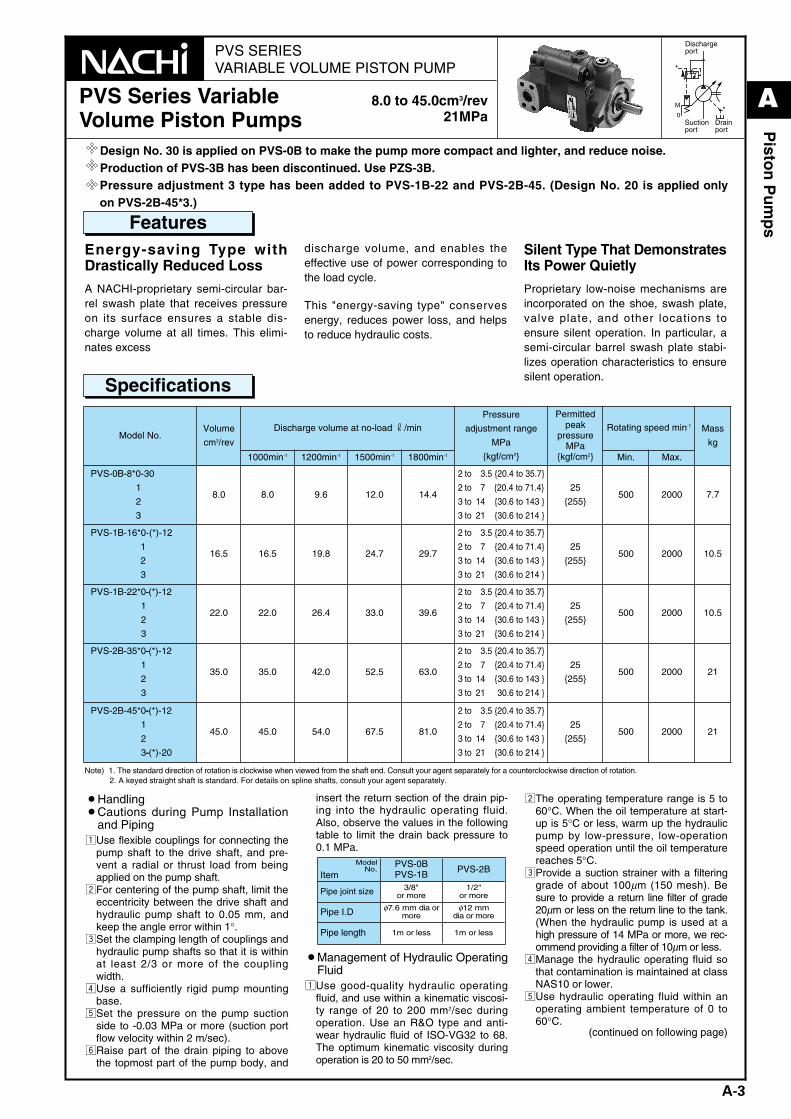
PVS SERIESVARIABLE VOLUME PISTON PUMP
0
M
*
*
Dischargeport
Suctionport
Drainport
PVS Series VariableVolume Piston Pumps
8.0 to 45.0cm3/rev21MPa
Features
Design No. 30 is applied on PVS-0B to make the pump more compact and lighter, and reduce noise.Production of PVS-3B has been discontinued. Use PZS-3B.Pressure adjustment 3 type has been added to PVS-1B-22 and PVS-2B-45. (Design No. 20 is applied onlyon PVS-2B-45*3.)
Specifications
Energy-saving Type withDrastically Reduced Loss
A NACHI-proprietary semi-circular bar-rel swash plate that receives pressureon its surface ensures a stable dis-charge volume at all times. This elimi-nates excess
discharge volume, and enables theeffective use of power corresponding tothe load cycle.
This "energy-saving type" conservesenergy, reduces power loss, and helpsto reduce hydraulic costs.
Silent Type That DemonstratesIts Power Quietly
Proprietary low-noise mechanisms areincorporated on the shoe, swash plate,valve plate, and other locations toensure silent operation. In particular, asemi-circular barrel swash plate stabi-lizes operation characteristics to ensuresilent operation.
¡Handling¡Cautions during Pump Installation
and PipingzUse flexible couplings for connecting the
pump shaft to the drive shaft, and pre-vent a radial or thrust load from beingapplied on the pump shaft.
xFor centering of the pump shaft, limit theeccentricity between the drive shaft andhydraulic pump shaft to 0.05 mm, andkeep the angle error within 1°.
cSet the clamping length of couplings andhydraulic pump shafts so that it is withinat least 2/3 or more of the couplingwidth.
vUse a sufficiently rigid pump mountingbase.
bSet the pressure on the pump suctionside to -0.03 MPa or more (suction portflow velocity within 2 m/sec).
nRaise part of the drain piping to abovethe topmost part of the pump body, and
insert the return section of the drain pip-ing into the hydraulic operating fluid.Also, observe the values in the followingtable to limit the drain back pressure to0.1 MPa.
¡Management of Hydraulic OperatingFluid
zUse good-quality hydraulic operatingfluid, and use within a kinematic viscosi-ty range of 20 to 200 mm2/sec duringoperation. Use an R&O type and anti-wear hydraulic fluid of ISO-VG32 to 68.The optimum kinematic viscosity duringoperation is 20 to 50 mm2/sec.
xThe operating temperature range is 5 to60°C. When the oil temperature at start-up is 5°C or less, warm up the hydraulicpump by low-pressure, low-operationspeed operation until the oil temperaturereaches 5°C.
cProvide a suction strainer with a filteringgrade of about 100µm (150 mesh). Besure to provide a return line filter of grade20µm or less on the return line to the tank.(When the hydraulic pump is used at ahigh pressure of 14 MPa or more, we rec-ommend providing a filter of 10µm or less.
vManage the hydraulic operating fluid sothat contamination is maintained at classNAS10 or lower.
bUse hydraulic operating fluid within anoperating ambient temperature of 0 to60°C.
(continued on following page)
Model No.
ItemPVS-0BPVS-1B PVS-2B
Pipe joint size 3/8"or more
1/2"or more
Pipe I.D φ7.6 mm dia ormore
φ12 mmdia or more
Pipe length 1m or less 1m or less
Model No.Volume
cm3/rev
Discharge volume at no-load r/minPressure
adjustment range
MPa
{kgf/cm2}
Permittedpeak
pressureMPa
{kgf/cm2}
Rotating speed min-1 Mass
kg
1000min-1 1200min-1 1500min-1 1800min-1 Min. Max.
PVS-0B-8*0-30
1
2
3
8.0 8.0 9.6 12.0 14.4
2 to 13.5 {20.4 to 35.7}
2 to 17.5 {20.4 to 71.4}
3 to 14. 5{30.6 to 143 }
3 to 21. 5{30.6 to 214 }
25
{255}500 2000 7.7
PVS-1B-16*0-(*)-12
1
2
3
16.5 16.5 19.8 24.7 29.7
2 to 13.5 {20.4 to 35.7}
2 to 17. 5{20.4 to 71.4}
3 to 14 .5{30.6 to 143 }
3 to 21. 5{30.6 to 214 }
25
{255}500 2000 10.5
PVS-1B-22*0--(*)-12
1
2
3
22.0 22.0 26.4 33.0 39.6
2 to 13.5 {20.4 to 35.7}
2 to 17. 5{20.4 to 71.4}
3 to 14. 5{30.6 to 143 }
3 to 21. 5{30.6 to 214 }
25
{255}500 2000 10.5
PVS-2B-35*0--(*)-12
1
2
3
35.0 35.0 42.0 52.5 63.0
2 to 13.5 {20.4 to 35.7}
2 to 17. 5{20.4 to 71.4}
3 to 14 .5{30.6 to 143 }
3 to 21.{ 30.6 to 214 }
25
{255}500 2000 21
PVS-2B-45*0--(*)-12
1
2
3--(*)-20
45.0 45.0 54.0 67.5 81.0
2 to 13.5 {20.4 to 35.7}
2 to 17. 5{20.4 to 71.4}
3 to 14. 5{30.6 to 143 }
3 to 21 .5{30.6 to 214 }
25
{255}500 2000 21
Note) 1. The standard direction of rotation is clockwise when viewed from the shaft end. Consult your agent separately for a counterclockwise direction of rotation.2. A keyed straight shaft is standard. For details on spline shafts, consult your agent separately.
A_Piston(P01-15)_E.q 03.11.20 0:45 PM Page 3
A
A-4
Pisto
n P
um
ps
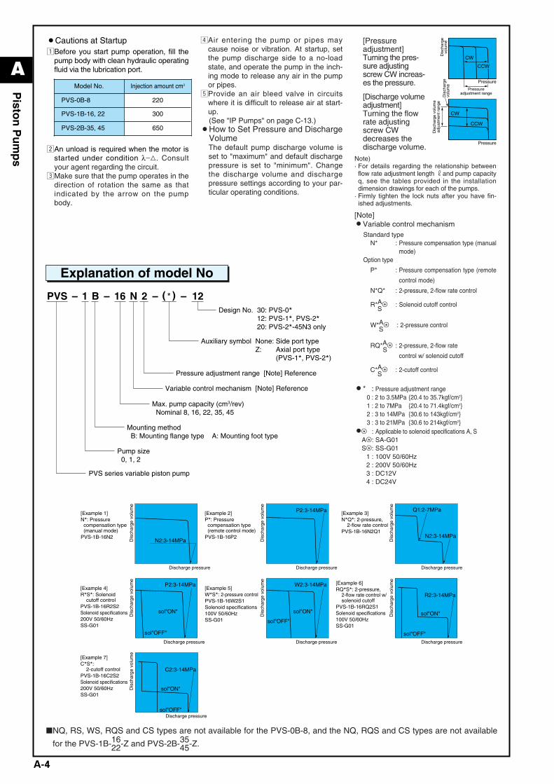
¡Cautions at StartupzBefore you start pump operation, fill the
pump body with clean hydraulic operatingfluid via the lubrication port.
xAn unload is required when the motor isstarted under condition λ_3. Consultyour agent regarding the circuit.
cMake sure that the pump operates in thedirection of rotation the same as thatindicated by the arrow on the pumpbody.
vAir entering the pump or pipes maycause noise or vibration. At startup, setthe pump discharge side to a no-loadstate, and operate the pump in the inch-ing mode to release any air in the pumpor pipes.
bProvide an air bleed valve in circuitswhere it is difficult to release air at start-up. (See "IP Pumps" on page C-13.)
¡How to Set Pressure and DischargeVolumeThe default pump discharge volume isset to "maximum" and default dischargepressure is set to "minimum". Changethe discharge volume and dischargepressure settings according to your par-ticular operating conditions.
[Pressureadjustment]Turning the pres-sure adjustingscrew CW increas-es the pressure.
[Discharge volumeadjustment]Turning the flowrate adjusting screw CWdecreases thedischarge volume.
Note)· For details regarding the relationship betweenflow rate adjustment length rand pump capacityq, see the tables provided in the installationdimension drawings for each of the pumps.
· Firmly tighten the lock nuts after you have fin-ished adjustments.
[Note]¡Variable control mechanism
Standard typeN* : Pressure compensation type (manual
mode)Option type
P* : Pressure compensation type (remote
control mode)
N*Q* : 2-pressure, 2-flow rate control
R*A&* : Solenoid cutoff controlS
W*A&* : 2-pressure controlS
RQ*A&* : 2-pressure, 2-flow rateS
control w/ solenoid cutoff
C*A&* : 2-cutoff controlS
¡* : Pressure adjustment range0 : 2 to 3.5MPa {20.4 to 35.7kgf/cm2}1 : 2 to 7MPa {20.4 to 71.4kgf/cm2}2 : 3 to 14MPa {30.6 to 143kgf/cm2}3 : 3 to 21MPa {30.6 to 214kgf/cm2}
¡&* : Applicable to solenoid specifications A, SA&* : SA-G01S&* : SS-G01
1 : 100V 50/60Hz2 : 200V 50/60Hz3 : DC12V4 : DC24V
122N16B1– – – –PVSDesign No. 30: PVS-0*
12: PVS-1*, PVS-2*20: PVS-2*-45N3 only
Pressure adjustment range [Note] Reference
Variable control mechanism [Note] Reference
Max. pump capacity (cm3/rev) Nominal 8, 16, 22, 35, 45
Mounting method B: Mounting flange type A: Mounting foot type
Pump size 0, 1, 2
PVS series variable piston pump
Auxiliary symbol None:Z:
Side port typeAxial port type(PVS-1*, PVS-2*)
*( )
Explanation of model No
Model No. Injection amount cm3
PVS-0B-8 220
PVS-1B-16, 22 300
PVS-2B-35, 45 650
❚NQ, RS, WS, RQS and CS types are not available for the PVS-0B-8, and the NQ, RQS and CS types are not available
for the PVS-1B-1622-Z and PVS-2B-35
45-Z.
CW
CCW
Pressureadjustment range
Dis
char
gevo
lum
eD
isch
arge
volu
me
Dis
char
ge v
olum
ead
just
men
t ran
ge
CW
CCW
Pressure
Pressure
N2:3-14MPaDis
char
ge v
olum
eD
isch
arge
vol
ume
Dis
char
ge v
olum
eD
isch
arge
vol
ume
Dis
char
ge v
olum
eD
isch
arge
vol
ume
Dis
char
ge v
olum
e
[Example 1]N*: Pressure compensation type (manual mode)PVS-1B-16N2
P2:3-14MPa[Example 2]P*: Pressure compensation type (remote control mode)PVS-1B-16P2
P2:3-14MPa
sol"ON"
sol"OFF"
[Example 4]R*S*: Solenoid cutoff controlPVS-1B-16R2S2Solenoid specifications200V 50/60HzSS-G01
W2:3-14MPa
sol"ON"
sol"OFF"
[Example 5]W*S*: 2-pressure controlPVS-1B-16W2S1Solenoid specifications100V 50/60HzSS-G01
N2:3-14MPa
Q1:2-7MPa
Discharge pressure
[Example 3]N*Q*: 2-pressure, 2-flow rate controlPVS-1B-16N2Q1
R2:3-14MPa
sol"ON"
sol"OFF"Discharge pressure
Discharge pressure
Discharge pressure
Discharge pressure
Discharge pressure
[Example 6]RQ*S*: 2-pressure, 2-flow rate control w/ solenoid cutoffPVS-1B-16RQ2S1Solenoid specifications100V 50/60HzSS-G01
C2:3-14MPa
sol"ON"
sol"OFF"Discharge pressure
[Example 7]C*S*: 2-cutoff controlPVS-1B-16C2S2Solenoid specifications200V 50/60HzSS-G01
A_Piston(P01-15)_E.q 03.11.20 0:45 PM Page 4
A
A-5
Pisto
n P
um
ps
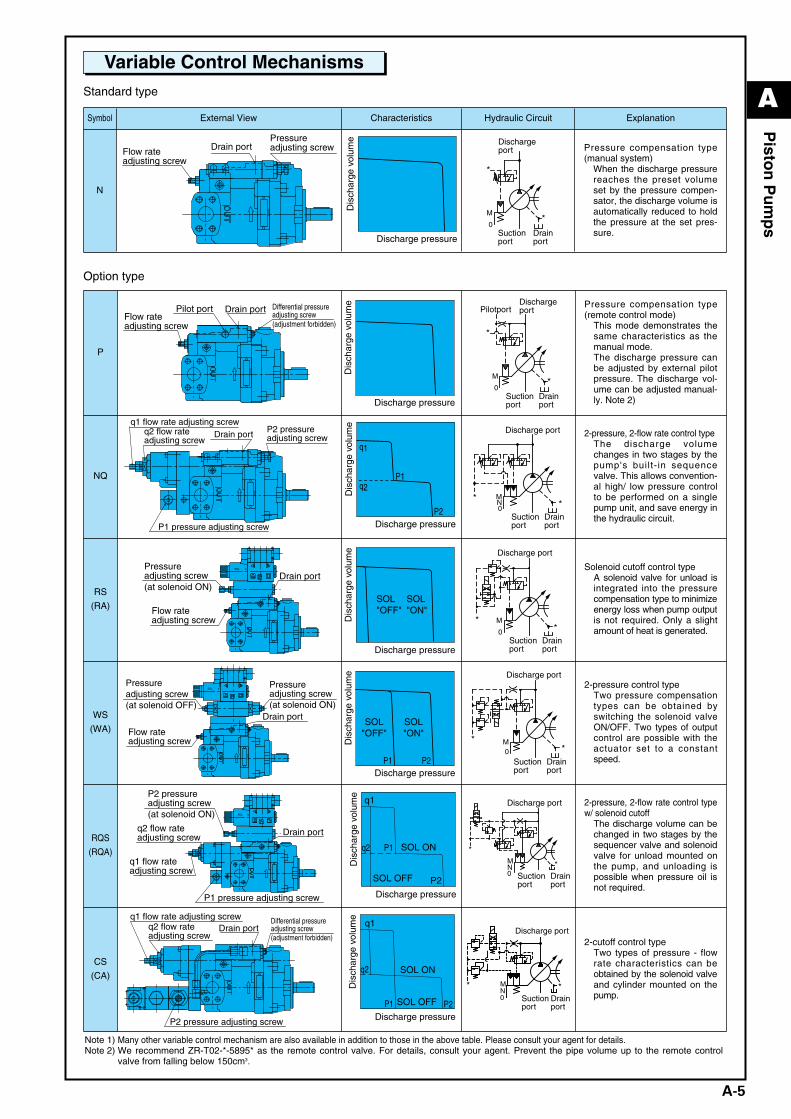
Variable Control MechanismsStandard type
Option type
Symbol External View Characteristics Hydraulic Circuit Explanation
N
NA
CH
I
Drain portPressureadjusting screwFlow rate
adjusting screw
Dis
char
ge v
olum
e
Discharge pressure
0
M
*
*
Dischargeport
Suctionport
Drainport
Pressure compensation type(manual system)
When the discharge pressurereaches the preset volumeset by the pressure compen-sator, the discharge volume isautomatically reduced to holdthe pressure at the set pres-sure.
P
NA
CH
I
Drain portFlow rateadjusting screw
Pilot port Differential pressureadjusting screw(adjustment forbidden)
Dis
char
ge v
olum
e
Discharge pressure
0
M*
*
PilotportDischargeport
Suctionport
Drainport
Pressure compensation type(remote control mode)
This mode demonstrates thesame characteristics as themanual mode.The discharge pressure canbe adjusted by external pilotpressure. The discharge vol-ume can be adjusted manual-ly. Note 2)
NQ
NA
CH
I
P1 pressure adjusting screw
q1 flow rate adjusting screwq2 flow rateadjusting screw
P2 pressureadjusting screwDrain port
q2
q1
P1
P2
Dis
char
ge v
olum
e
Discharge pressure
0
MN *
*
Discharge port
Suctionport
Drainport
2-pressure, 2-flow rate control typeThe discharge volumechanges in two stages by thepump's built- in sequencevalve. This allows convention-al high/ low pressure controlto be performed on a singlepump unit, and save energy inthe hydraulic circuit.
RS
(RA)
SOL b
NA
CH
I
Drain portPressureadjusting screw(at solenoid ON)
Flow rateadjusting screw
SOL"OFF"
SOL"ON"
Dis
char
ge v
olum
e
Discharge pressure
0
M*
*
Discharge port
Suctionport
Drainport
Solenoid cutoff control typeA solenoid valve for unload isintegrated into the pressurecompensation type to minimizeenergy loss when pump outputis not required. Only a slightamount of heat is generated.
WS
(WA)
NA
CH
I
Drain port
Pressureadjusting screw(at solenoid OFF)
Flow rateadjusting screw
Pressureadjusting screw(at solenoid ON)
SOL b
SOL"OFF"
P1 P2
SOL"ON"
Dis
char
ge v
olum
e
Discharge pressure
0M*
*
Discharge port
Suctionport
Drainport
2-pressure control typeTwo pressure compensationtypes can be obtained byswitching the solenoid valveON/OFF. Two types of outputcontrol are possible with theactuator set to a constantspeed.
RQS
(RQA)
SOL b
NA
CH
I
Drain port
P1 pressure adjusting screw
P2 pressureadjusting screw(at solenoid ON)
q1 flow rateadjusting screw
q2 flow rateadjusting screw
P2
q1
q2 P1
SOL OFF
SOL ON
Dis
char
ge v
olum
e
Discharge pressure
*
*0
MN
Discharge port
Suctionport
Drainport
2-pressure, 2-flow rate control typew/ solenoid cutoff
The discharge volume can bechanged in two stages by thesequencer valve and solenoidvalve for unload mounted onthe pump, and unloading ispossible when pressure oil isnot required.
CS
(CA)
NA
CH
I
Drain port
P2 pressure adjusting screw
q1 flow rate adjusting screwq2 flow rateadjusting screw
Differential pressureadjusting screw(adjustment forbidden)
q1
q2
P1 P2SOL OFF
SOL ON
Dis
char
ge v
olum
e
Discharge pressure
* *0
MN
Discharge port
Suctionport
Drainport
2-cutoff control typeTwo types of pressure - flowrate characteristics can beobtained by the solenoid valveand cylinder mounted on thepump.
Note 1) Many other variable control mechanism are also available in addition to those in the above table. Please consult your agent for details.Note 2) We recommend ZR-T02-*-5895* as the remote control valve. For details, consult your agent. Prevent the pipe volume up to the remote control
valve from falling below 150cm3.
A_Piston(P01-15)_E.q 03.11.20 0:45 PM Page 5
A
A-6
Pisto
n P
um
ps
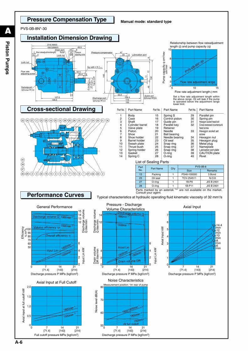
Manual mode: standard type
Typical characteristics at hydraulic operating fluid kinematic viscosity of 32 mm2/s
PVS-0B-8N*-30
List of Sealing Parts
Pressure Compensation Type
Installation Dimension Drawing
Cross-sectional Drawing
Performance Curves
Discharge portSuction port
G(Former PF)1/2G(Former PF)3/4
MINPressure compensator
Lubrication port
Drain portRc3/8
Lock nut
0–0.012
Discharge portG(Former PF)1/2
Lock nut
142
6
29
110130
R46
106.4
4911
47
78
53.2
132
77
3
11
164.5(MAX)
(flow rateadjustmentlength)18 6
19.0
521
.282
.6
149.5
14
127.5
49.5
525.4
214( MAX)
42.5
510
0 –0.0
210 –0.2
5
f–0
.036
–0.0
71
Flow rateadjusting screw
Pressureadjusting screw
Key width 4.76
Part No. Part Name Part No. Part Name Part No. Part Name
123456789
1011121314
BodyCaseShaftCylinder barrelValve platePistonShoeShoe holderBarrel holderSwash plateThrust bushSpring holderGasketSpring C
1516171819202122232425262728
Spring S Control pistonGuide pinParallel keyRetainerNeedleBall bearingNeedle bearingOil sealSnap ringSnap ringSnap ringO-ringO-ring
29303132
33
34353637383940
Parallel pinSpring pinHexagon socket head boltCross-recessed countersunkhead screwHexagon socket setscrewHexagon nutHexagon plugMetal plugNameplateLubrication port plateCAUTION plateRivet
Parts marked by an asterisk "*" are not available on the market.Consult your agent.
10
10
8
6
4
2
3
5 15
PVS-0B-8N*-30
cm3 /
rev
Relationship between flow rateadjustmentlength ( ) and pump capacity (q)
Pum
p ca
paci
ty q
cm
3 /re
v
Flow rate adjustment range
Flow rate adjustment length mm
Discharge volume Q
Volume efficiency ηv
Overall efficiency η
Input Lin
1800min–1
1800min–1
1500min–1
1500min–1
14{143}
7{71.4}
0
5060
15141312
6
4
2
0
708090
100
Discharge pressure P MPa {kgf/cm2}
General Performance
21{214}
Input Lin
Drain volume DR
Discharge volume Q1800min–1
1800min–1
1500min–1
1500min–1
14{143}
7{71.4}
00
2
4
6
4
2
0
14
12
Discharge pressure P MPa {kgf/cm2}
Pressure - DischargeVolume Characteristics
21{214}
1800min–1
1500min–1 1500/1800min–1
1500min–1
14{143}
7{71.4}
0
2.0
1.5
1.0
0.5
0
Full cutoff pressure MPa {kgf/cm2}
Axial Input at Full Cutoff
21{214}
14{143}
7{71.4}
050
60
80
70
Discharge pressure P MPa {kgf/cm2}
At full cutoff
Measurement position: 1m rear of pump
Noise Characteristics
21{214}
Q=14.4r/minQ=12r/minQ=10r/minQ=8r/minQ=6r/min
14{143}
7{71.4}
00
1
2
7
6
5
4
3
Discharge pressure P MPa {kgf/cm2}
Axial Input
21{214}
1800min–1
Effi
cien
cyη,
ηv%
Dis
char
ge v
olum
eQ
lite
r/m
inIn
put L
in k
W
Inpu
t Lin
kW
Dis
char
ge v
olum
eQ
lite
r/m
inD
rain
vol
ume
DR
lite
r/m
in
Axi
al In
put k
W
Axi
al in
put a
t ful
l cut
off k
W
Noi
se le
vel d
B(A
)Set a flow rate adjustment length withinthe above range. Oil will leak if the pumpis operated below the adjustment rangelower limit.
PartNo.
Part Name Q'tyPVS-0B-8
Size Remarks
13 Packing 1 PS46-100000 3 Bond
23 Oil seal 1 TCV-254511 N.O.K
27 O-ring 1 1B-P9 JIS B 2401
28 O-ring 1 1B-P11 JIS B 2401
A_Piston(P01-15)_E.q 03.11.20 0:46 PM Page 6
A
A-7
Pisto
n P
um
ps
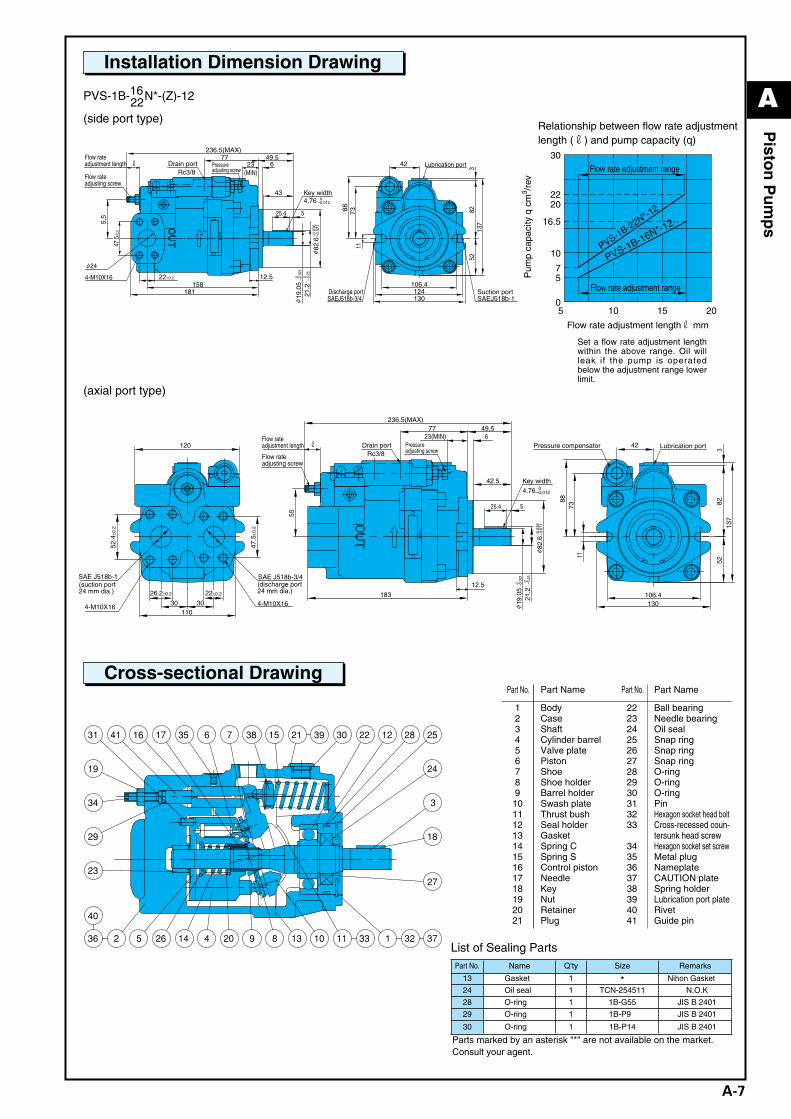
Installation Dimension Drawing
Cross-sectional Drawing
PVS-1B-16N*-(Z)-1222(side port type)
(axial port type)
Parts marked by an asterisk "*" are not available on the market.Consult your agent.
List of Sealing Parts
Part No. Part Name Part No. Part Name
123456789
101112131415161718192021
BodyCaseShaftCylinder barrelValve platePistonShoeShoe holderBarrel holderSwash plateThrust bushSeal holderGasketSpring CSpring SControl pistonNeedleKeyNutRetainerPlug
222324252627282930313233
3435363738394041
Ball bearingNeedle bearingOil sealSnap ringSnap ringSnap ringO-ringO-ringO-ringPinHexagon socket head boltCross-recessed coun-tersunk head screwHexagon socket set screwMetal plugNameplateCAUTION plateSpring holderLubrication port plateRivetGuide pin
Part No. Name Q'ty Size Remarks
13 Gasket 1 * Nihon Gasket
24 Oil seal 1 TCN-254511 N.O.K
28 O-ring 1 1B-G55 JIS B 2401
29 O-ring 1 1B-P9 JIS B 2401
30 O-ring 1 1B-P14 JIS B 2401
(MIN)
NA
CH
I
Drain portRc3/8
Key width4.76 0
–0.012
4-M10X16
24
Lubrication port
Discharge portSAEJ518b-3/4
Suction portSAEJ518b-1
525.4
12.5158
22±0.2
47.5
±0.2
649.577
181
5.5
236.5(MAX)
43
23
106.4
130
52
117388
42
124
8213
73
rFlow rateadjustment length
19.0
521
.282
.6
0–0
.021
0–0
.25
φ
φ
–0.0
36–0
.071
φ
Flow rateadjusting screw
Pressureadjusting screw
NA
CH
I
Rc3/8
4.76 0–0.012
4-M10X164-M10X16
SAE J518b-3/4SAE J518b-1
525.4
12.5
649.577
55
236.5(MAX)
42.5
23(MIN)
183 106.4130
52
1173
88
42
82
137
3
3030110
52.4
±0.2
47.5
±0.2
120 r
19.0
521
.2
82.6
0 –0.0
210 –0
.25
φ
φ
–0.0
36–0
.071
22±0.226.2±0.2
(suction port24 mm dia.)
(discharge port24 mm dia.)
Flow rateadjusting screw
Flow rateadjustment length Drain port Pressure
adjusting screw
Key width
Pressure compensator Lubrication port
5 10 15
10
20
Flow rate adjustment lengthr mm
PVS-1B-16N*-12
PVS-1B-22N*-12
0
30
20
16.5
22
7 5
Flow rate adjustment range
Flow rate adjustment range
Relationship between flow rate adjustmentlength (r) and pump capacity (q)
Pum
p ca
paci
ty q
cm
3 /rev
Set a flow rate adjustment lengthwithin the above range. Oil willleak if the pump is operatedbelow the adjustment range lowerlimit.
A_Piston(P01-15)_E.q 03.11.20 0:46 PM Page 7
A
A-8
Pisto
n P
um
ps
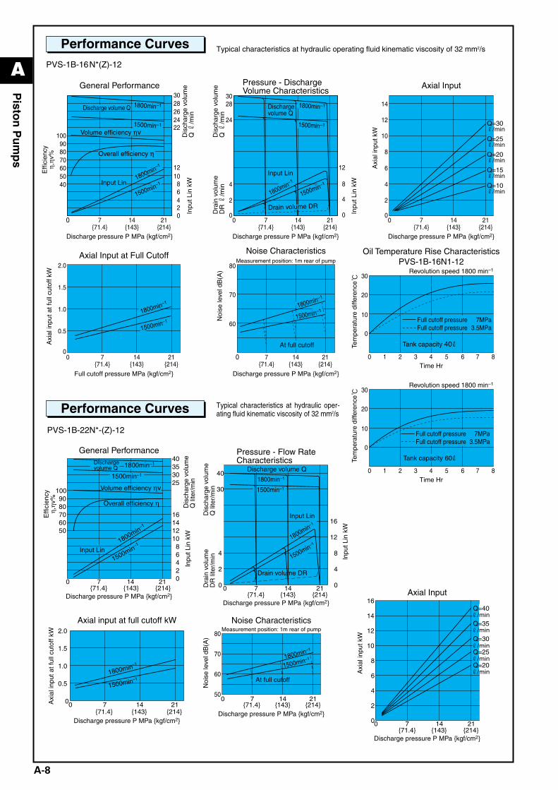
Performance Curves Typical characteristics at hydraulic operating fluid kinematic viscosity of 32 mm2/s
PVS-1B-16N*(Z)-12
Discharge volume Q Dischargevolume Q
Volume efficiency ηv
Overall efficiency η
Input Lin
1800min–1
1800min–1
1500min–1
1500min–1
14{143}
7{71.4}
0
5040
60
3028262422
12
810
42
6
0
708090
100
Discharge pressure P MPa {kgf/cm2}
General Performance
21{214}
Input Lin
Drain volume DR
1800min–1
1800min–1
1500min–1
1500min–1
14{143}
7{71.4}
00
2
4
12
8
4
0
2830
24
Discharge pressure P MPa {kgf/cm2}
Pressure - DischargeVolume Characteristics
21{214}
1800min–1
1500min–1
1800min–1
1500min–1
14{143}
7{71.4}
0
2.0
1.5
1.0
0.5
0
Full cutoff pressure MPa {kgf/cm2}
Axial Input at Full Cutoff
21{214}
14{143}
7{71.4}
0
60
80
70
Discharge pressure P MPa {kgf/cm2}
At full cutoff
Full cutoff pressureFull cutoff pressure
7MPa3.5MPa
Tank capacity 40
Measurement position: 1m rear of pump
Revolution speed 1800 min–1
Noise Characteristics
21{214}
Q=30r/min
Q=25r/min
Q=20r/min
Q=15r/min
Q=10r/min
14{143}
7{71.4}
00
2
4
14
12
10
8
6
Discharge pressure P MPa {kgf/cm2}
Axial Input
21{214}
640 1 3 5 72
0
30
20
10
Time Hr
Oil Temperature Rise CharacteristicsPVS-1B-16N1-12
8
Full cutoff pressureFull cutoff pressure
7MPa3.5MPa
Tank capacity 60
Revolution speed 1800 min–1
640 1 3 5 72
0
30
20
10
Time Hr8
Effi
cien
cyη,
ηv%
Dis
char
ge v
olum
eQ
r/m
inIn
put L
in k
W
Inpu
t Lin
kW
Axi
al in
put k
W
Dra
in v
olum
eD
R r
/min
Dis
char
ge v
olum
eQ
r/m
in
Axi
al in
put a
t ful
l cut
off k
W
Noi
se le
vel d
B(A
)
Tem
pera
ture
diff
eren
ceTe
mpe
ratu
re d
iffer
ence
Performance Curves Typical characteristics at hydraulic oper-ating fluid kinematic viscosity of 32 mm2/s
PVS-1B-22N*-(Z)-12
0 7 14 0
4
8
12
1800min–1
1500min–1
Input Lin
6050
708090
100
40353025
21
1614
10
6
2
{71.4} {143} {214}Discharge pressure P MPa {kgf/cm2}
Overall efficiency η
1800min–1
1500min–1
General PerformanceDischargevolume Q
Dis
char
ge v
olum
eQ
lite
r/m
inIn
put L
in k
W
Effi
cien
cyη,
ηv%
Volume efficiency ηv
2170 14 0
4
8
12
Input Lin
1800min–1
1500min–1
{143}{71.4}
40
{214}
30
16
1800min–1
1500min–1
Pressure - Flow RateCharacteristics
0
2
4
Drain volume DR
Discharge pressure P MPa {kgf/cm2}
Dis
char
ge v
olum
eQ
lite
r/m
inD
rain
vol
ume
DR
lite
r/m
in
Discharge volume Q
Inpu
t Lin
kW
21
14
70 140
4
8
12
{143}
6
{71.4} {214}
2
10
16Axial Input
Q=40
Q=35
Q=30
Q=25
Q=20
r/min
r/min
r/min
r/min
r/min
Discharge pressure P MPa {kgf/cm2}
Axi
al in
put k
W
7
1500min–11800min–1
{214}0
2.0
21140
{143}
0.5
1.0
1.5
Axial input at full cutoff kW
{71.4}Discharge pressure P MPa {kgf/cm2}
Axi
al in
put a
t ful
l cut
off k
W
{143}21
{214}
60
500
80
1800min–1
1500min–1
7 14
70
Noise Characteristics
{71.4}
Measurement position: 1m rear of pump
At full cutoff
Discharge pressure P MPa {kgf/cm2}
Noi
se le
vel d
B(A
)
A_Piston(P01-15)_E.q 03.11.20 0:46 PM Page 8
A
A-9
Pisto
n P
um
ps
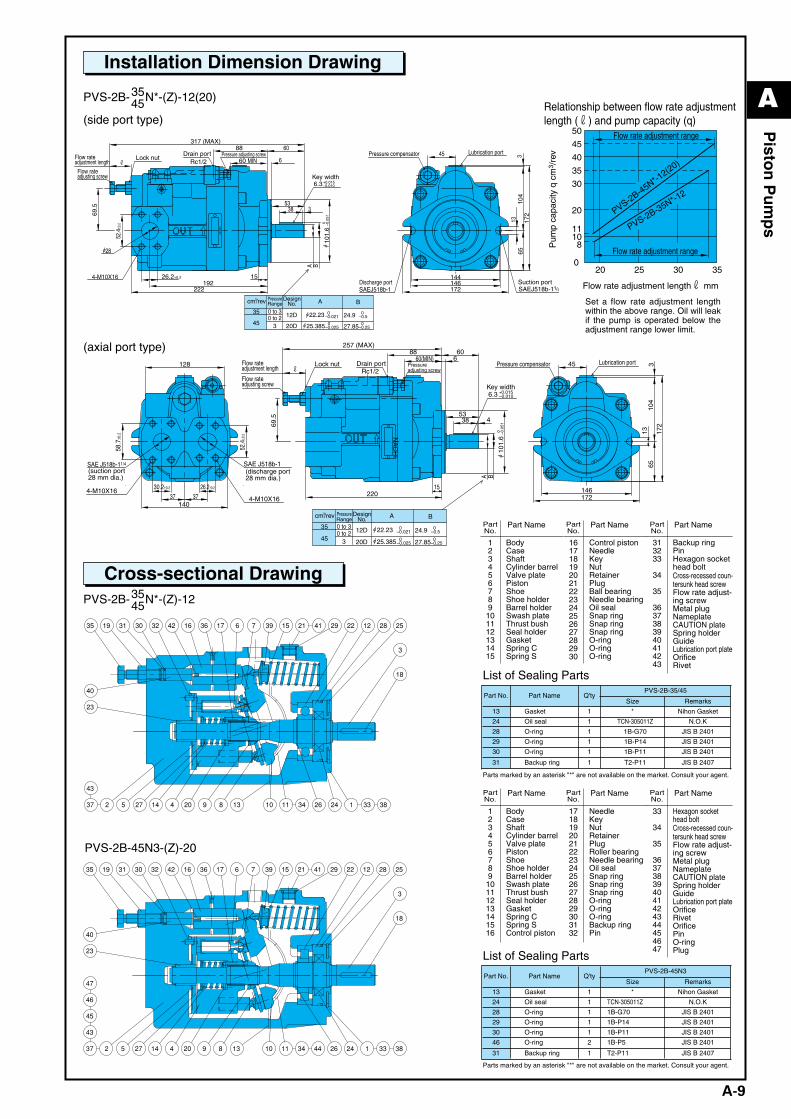
Installation Dimension Drawing
PVS-2B-35N*-(Z)-1245
Cross-sectional Drawing
PVS-2B-35N*-(Z)-12(20)45(side port type)
(axial port type)
PVS-2B-45N3-(Z)-20
PartNo.
Part Name
123456789
101112131415
BodyCaseShaftCylinder barrelValve platePistonShoeShoe holderBarrel holderSwash plateThrust bushSeal holderGasketSpring CSpring S
PartNo.
Part Name
161718192021222324252627282930
Control pistonNeedleKeyNutRetainerPlugBall bearingNeedle bearingOil sealSnap ringSnap ringSnap ringO-ringO-ringO-ring
PartNo.
Part Name
313233
34
35
3637383940414243
Backup ringPinHexagon sockethead boltCross-recessed coun-tersunk head screwFlow rate adjust-ing screwMetal plugNameplateCAUTION plateSpring holderGuideLubrication port plateOrificeRivet
List of Sealing Parts
PartNo.
Part Name
123456789
10111213141516
BodyCaseShaftCylinder barrelValve platePistonShoeShoe holderBarrel holderSwash plateThrust bushSeal holderGasketSpring CSpring SControl piston
PartNo.
Part Name
17181920212223242526272829303132
NeedleKeyNutRetainerPlugRoller bearingNeedle bearingOil sealSnap ringSnap ringSnap ringO-ringO-ringO-ringBackup ringPin
List of Sealing Parts
PartNo.
Part Name
33
34
35
363738394041424344454647
Hexagon sockethead boltCross-recessed coun-tersunk head screwFlow rate adjust-ing screwMetal plugNameplateCAUTION plateSpring holderGuideLubrication port plateOrificeRivetOrificePinO-ringPlug
Parts marked by an asterisk "*" are not available on the market. Consult your agent.
Parts marked by an asterisk "*" are not available on the market. Consult your agent.
NA
CH
I
Pressure adjusting screwLock nut
A Bcm3/rev
0 to 30 to 2
3
22.23 0–0.021
0–0.524.9
25.385 0–0.025
0–0.2527.85
12D
20D
35
45
Pressure compensator Lubrication port
Suction portDischarge port
101.
6
53338
60
6
19215
28
88317 (MAX)
222
69.5
60 MIN
A B
144146172
6513
345
104
172
r
Drain portRc1/2
Key width6.3+0.015
–0.010
4-M10X16
SAEJ518b-1 SAEJ518b-1 4
26.2±0.2
52.4
±0.2 0 –0
.051
1/
Flow rateadjustment length
Flow rateadjusting screw
PressureRange
DesignNo.
020
10
Flow rate adjustment lengthr mm
20
30
40
50
PVS-2B-35N*-12
PVS-2B-45N*-12(20)
45
35
11
8
25 30 35
Flow rate adjustment range
Flow rate adjustment range
Relationship between flow rate adjustmentlength (r) and pump capacity (q)
Pum
p ca
paci
ty q
cm
3 /re
v
NA
CH
I
Drain portLock nut
Key width
Pressure compensator Lubrication port
SAE J518b-1
4-M10X16
53438
6
15
88
69.5
220
6060(MIN)
146172
6513
45 310
417
2
128
52.4
±0.2
58.7
±0.2
30.2±0.2
37 37140
26.2±0.24-M10X16
SAE J518b-11/4
Rc1/2
257 (MAX)
r
6.3 +0.015–0.010
A Bcm3/rev
3
22.23 0–0.021
0–0.524.9
25.385 0–0.025
0–0.2527.85
12D
20D
35
45
101.
6
A B0 –0
.051
Pressureadjusting screw
Flow rateadjustment length
Flow rateadjusting screw
PressureRange
DesignNo.
(suction port28 mm dia.)
(discharge port28 mm dia.)
0 to 30 to 2
Part No. Part Name Q'tyPVS-2B-35/45
Size Remarks
13 Gasket 1 * Nihon Gasket
24 Oil seal 1 TCN-305011Z N.O.K
28 O-ring 1 1B-G70 JIS B 2401
29 O-ring 1 1B-P14 JIS B 2401
30 O-ring 1 1B-P11 JIS B 2401
31 Backup ring 1 T2-P11 JIS B 2407
Part No. Part Name Q'tyPVS-2B-45N3
Size Remarks
13 Gasket 1 * Nihon Gasket
24 Oil seal 1 TCN-305011Z N.O.K
28 O-ring 1 1B-G70 JIS B 2401
29 O-ring 1 1B-P14 JIS B 2401
30 O-ring 1 1B-P11 JIS B 2401
46 O-ring 2 1B-P5 JIS B 2401
31 Backup ring 1 T2-P11 JIS B 2407
Set a flow rate adjustment lengthwithin the above range. Oil will leakif the pump is operated below theadjustment range lower limit.
A_Piston(P01-15)_E.q 03.11.20 0:46 PM Page 9
A
A-10
Pisto
n P
um
ps
Discharge volume Q
Volume efficiency ηv
Overall efficiency η
Input Lin
1800min–1
1800min–1
1500min–1
1500min–1
14{143}
7{71.4}
0
5060
65605550
30
20
10
0
708090
100
Discharge pressure P MPa {kgf/cm2} Discharge pressure P MPa {kgf/cm2}
General Performance
21{214}
Input Lin
14{143}
7{71.4}
00
2
4
30
20
10
0
70
60
50
21{214}
1800min–1
1500min–1
14{143}
7{71.4}
0
4
3
2
1
0
Full cutoff pressure MPa {kgf/cm2}
Axial Input at Full Cutoff
21{214}
14{143}
7{71.4}
00
4
8
28
24
20
16
12
Discharge pressure P MPa {kgf/cm2}
Axial Input
21{214}
Q=60r/min
Q=50r/min
Q=40r/min
Q=30r/min
Effi
cien
cyη,
ηv%
Dis
char
ge v
olum
eQ
r/m
inIn
put L
in k
W
Dischargevolume Q
Drain volumeDR
1800min–1
1800min–1
1500min–1
1500min–1
Pressure - DischargeVolume Characteristics
Inpu
t Lin
kW
Dra
in v
olum
eD
R r
/min
Dis
char
ge v
olum
eQ
r/m
in
Axi
al in
put k
W
Axi
al in
put a
t ful
l cut
off k
W
At full cutoff1500min–
11800min–1
{143}21
{214}
60
500
80
7 14
70
Noise Characteristics
{71.4}
Measurement position: 1m rear of pump
Discharge pressure P MPa {kgf/cm2}
Noi
se le
vel d
B(A
)
21{214}
5060
7{71.4}
0 14{143}
0
10
20
30
Input Lin 1800min–1
1500min–1
708090
100
7580
7065
Overall efficiency η
Volume efficiency ηv
Dischargevolume Q
1500min–1
General Performance
1800min–1
Discharge pressure P MPa {kgf/cm2}
Effi
cien
cyη,
ηv%
Dis
char
ge v
olum
eQ
lite
r/m
inIn
put L
in k
W
70
7
4
{214}
2
0 2114
1800min–1
0
{143}
10
20
1500min–1
30
0
Pressure - DischargeVolume Characteristics
{71.4}
80
60
Discharge pressure P MPa {kgf/cm2}
Input Lin
Discharge volume Q
Drain volume DR
1800min–1
1500min–1
Inpu
t Lin
kW
Dra
in v
olum
eD
R li
ter/
min
Dis
char
ge v
olum
eQ
lite
r/m
in
21
28
70 140
8
16
24
Q=80r/minQ=70r/minQ=60r/min
Q=50r/min
Q=40r/min
{143}
12
{71.4} {214}
4
20
32Axial Input
Discharge pressure P MPa {kgf/cm2}
Axi
al in
put k
W
{143}21
{214}
00
1800min–1
1500min–1
7 14
Axial Input at Full Cutoff
{71.4}
1
2
3
4
Full cutoff pressure MPa {kgf/cm2}
Axi
al in
put a
t ful
l cut
off k
W
At full cutoff1500min–11800min–1
{143}21
{214}
60
500
80
7 14
70
Noise Characteristics
{71.4}
Measurement position: 1m rear of pump
Discharge pressure P MPa {kgf/cm2}
Noi
se le
vel d
B(A
)
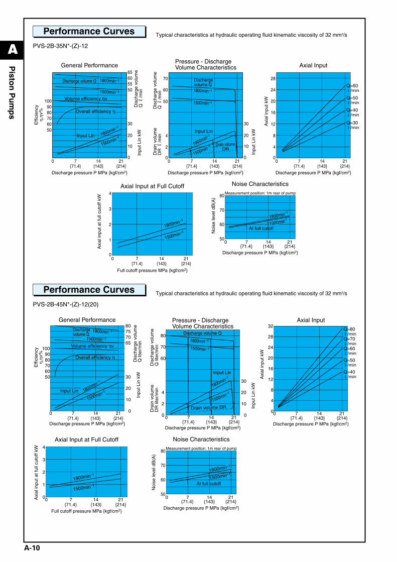
Performance Curves Typical characteristics at hydraulic operating fluid kinematic viscosity of 32 mm2/s
PVS-2B-35N*-(Z)-12
Performance Curves Typical characteristics at hydraulic operating fluid kinematic viscosity of 32 mm2/s
PVS-2B-45N*-(Z)-12(20)
A_Piston(P01-15)_E.q 03.11.20 0:46 PM Page 10
A
A-11
Pisto
n P
um
ps
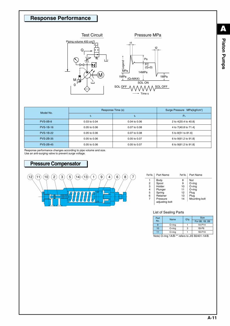
Response Performance
Pressure Compensator
Model No.Response Time (s) Surge Pressure MPa{kgf/cm2}
t1 t2 PS
PVS-0B-8 0.03 to 0.04 0.04 to 0.06 12 to 4{20.4 to 40.8}
PVS-1B-16 0.05 to 0.06 0.07 to 0.08 14 to 7{40.8 to 71.4}
PVS-1B-22 0.05 to 0.06 0.07 to 0.08 15 to 8{51 to 81.6}
PVS-2B-35 0.05 to 0.06 0.05 to 0.07 16 to 9{61.2 to 91.8}
PVS-2B-45 0.05 to 0.06 0.05 to 0.07 16 to 9{61.2 to 91.8}
0
MM
Ps
14MPa
1MPa 1MPa
FC
SOL ONSOL OFFSOL OFF
MPa
Time s
(Q=0)
(Q=MAX)
Q
t1
t2
Test CircuitPiping volume 400 cm3
Pressure MPa
Lege
nd
Response performance changes according to pipe volume and size. Use an anti-surging valve to prevent surge voltage.
Note) O-ring 1A/B-** refers to JIS B2401-1A/B.
List of Sealing Parts
PartNo.
Name Q'tySize
For 0B, 1B, 2B
9 O-ring 1 1A-P14
10 O-ring 3 1B-P6
11 O-ring 1 1B-P10
Part No. Part Name Part No. Part Name
1234567
BodySpoolHolderPlungerSpringRetainerPressure adjusting bolt
891011121314
NutO-ringO-ringO-ringPlugPlugMounting bolt
A_Piston(P01-15)_E.q 03.11.20 0:46 PM Page 11
A
A-12
Pisto
n P
um
ps
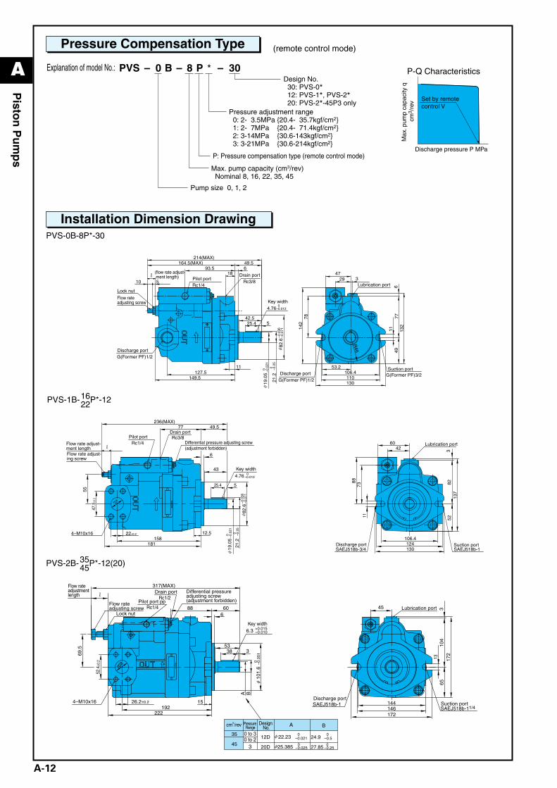
Pressure Compensation Type (remote control mode)
PVS-0B-8P*-30
PVS-2B-35P*-12(20)45
PVS-1B-16P*-1222
Rc1/4
NA
CH
I
Rc3/8
4.76
4–M10x16
SAEJ518b-3/4 SAEJ518b-1
525.4
12.5158
22±0.2
47.5
±0.2
6
49.577
181
55
43
236(MAX)
106.4
130
52
1173
88
42
124
8213
7
360
r
24f
19.0
5
21.2
82.6
0 –0.2
5
0–0
.021
φ
φ–0
.036
–0.0
71
0–0.012
Flow rate adjust-ment lengthFlow rate adjust-ing screw
Pilot portDrain port
Key width
Differential pressure adjusting screw(adjustment forbidden)
Lubrication port
Discharge port Suction port
G(Former PF)3/2
G(Former PF)1/2
Rc3/8
4.760
–0.012
Rc1/4
142
77
29
110130
R46
106.4
4911
47
78
53.2
132
6
3
11
164.5(MAX)6
19.0
5
21.2
82.6
149.5127.5
49.5
525.4
214(MAX)
42.5
510
93.518
0 –0.2
5
0 –0.0
21φ
φ–0
.036
–0.0
71r
(flow rate adjust- ment length) Pilot port
Drain port
Lock nut
Flow rate adjusting screw Key width
Discharge port
Discharge portSuction port
Lubrication port
G(Former PF)1/2
Explanation of model No.:
Pressure adjustment range 0: 2- 3.5MPa {20.4- 35.7kgf/cm2} 1: 2- 7MPa {20.4- 71.4kgf/cm2} 2: 3-14MPa {30.6-143kgf/cm2} 3: 3-21MPa {30.6-214kgf/cm2}
P: Pressure compensation type (remote control mode)
Max. pump capacity (cm3/rev) Nominal 8, 16, 22, 35, 45
Pump size 0, 1, 2
Design No. 30: PVS-0* 12: PVS-1*, PVS-2* 20: PVS-2*-45P3 only
30P8B0– – –PVS *
SAEJ518b-11/4SAEJ518b-1
Rc1/4
NA
CH
I
Rc1/2
4–M10x16
6.3 +0.015–0.010
144146172
6513
45
104
172
3
101.
6
53338
606
1921526.2±0.2
52.4
±0.2
88
317(MAX)
222
69.5
r
28φ
A B0 –0
.051
φ
φ
φ
A Bcm3/rev
3
22.23 0–0.021
0–0.524.9
25.385 0–0.025
0–0.2527.85
12D
20D
35
45
Pilot port pp
Lock nut
Drain port
Flow rate adjusting screw
Differential pressure adjusting screw (adjustment forbidden)
Lubrication port
Discharge portSuction port
Pressure Range
Design No.
Flow rate adjustment length
Key width
0 to 30 to 2
P-Q Characteristics
Set by remotecontrol V
Max
. pum
p ca
paci
ty q
cm
3 /re
v
Discharge pressure P MPa
Installation Dimension Drawing
A_Piston(P01-15)_E.q 03.11.20 0:46 PM Page 12
A
A-13
Pisto
n P
um
ps
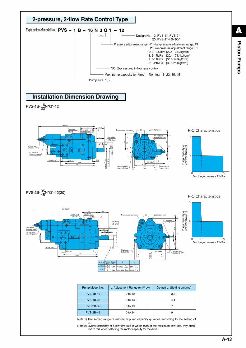
2-pressure, 2-flow Rate Control Type
PVS-1B-16N*Q*-1222
PVS-2B-35N*Q*-12(20)45
(MIN)
NA
CH
I
Rc3/8
4.76 0–0.012
4–M10x16
SAEJ518b-3/4 SAEJ518b-1
525.4
21.2
82.6
12.5158
22±0.2
47.5
±0.2
6
77
181
19.0
5
49.5
43
296(MAX)
23
106.4
130
521173
88
42
12482
137
3
107.5(MAX)
24φ
0–0
.25
–0.0
71–0
.036
0 –0.0
21φ
φ
Drain port P2 pressure adjusting screw
q1 flow rate adjusting screw
q2 flow rate adjusting screw
Key width
Pressure compensator Lubrication port
P1 pressure adjusting screw
Discharge port Suction port
NA
CH
I
Rc1/2
4–M10x16
6.3+0.015–0.010
SAEJ518b-11/4SAEJ518b-1
101.
6
53338
6
1921526.2±0.2
52.4
±0.2
88
222
352(MAX)
60
60(Min)
144146172
6513
45
107.5(MAX)
104
3
172
A B
0 –0.0
51φ
φ
φ
28φ
A Bcm3/rev
3
22.23 0–0.021
0–0.524.9
25.385 0–0.025
0–0.2527.85
12D
20D
35
45
Drain portP2 pressure adjusting screw
q1 flow rate adjusting screw
q2 flow rate adjusting screw
Key width
Pressure compensator Lubrication port
P1 pressure adjusting screw
Discharge portSuction port
Pressure Range
Design No.
0 to 30 to 2
NQ: 2-pressure, 2-flow rate control
Max. pump capacity (cm3/rev) Nominal 16, 22, 35, 45
Pump size 1, 2
Pressure adjustment range N*: High-pressure adjustment range, P2Q*: Low-pressure adjustment range, P10: 2- 3.5MPa {20.4- 35.7kgf/cm2}1: 2- 7MPa {20.4- 71.4kgf/cm2}2: 3-14MPa {30.6-143kgf/cm2}3: 3-21MPa {30.6-214kgf/cm2}
123 1QN16B1– – –12: PVS-1*, PVS-2*20: PVS-2*-45N3Q*
Design No.
Explanation of model No.: PVS
Pump Model No. q2 Adjustment Range (cm3/rev) Default q2 (Setting cm3/rev)
PVS-1B-16 0 to 10 3.3
PVS-1B-22 0 to 13 4.4
PVS-2B-35 0 to 19 7
PVS-2B-45 0 to 24 9
Note 1) The setting range of maximum pump capacity q1 varies according to the setting ofq2.
Note 2) Overall efficiency at a low flow rate is worse than at the maximum flow rate. Pay atten-tion to this when selecting the motor capacity for the drive.
Installation Dimension Drawing
P1
q1
q2
0 P2
P1
q1
q2
0 P2
P-Q Characteristics
Discharge pressure P MPa
Pum
p ca
paci
ty q
cm
3 /re
v (N
ote
2)
P-Q Characteristics
Discharge pressure P MPa
Pum
p ca
paci
ty q
cm
3 /re
v (N
ote
2)
A_Piston(P01-15)_E.q 03.11.20 0:46 PM Page 13
A
A-14
Pisto
n P
um
ps
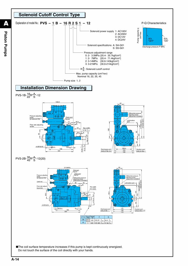
Solenoid Cutoff Control Type
PVS-1B-16R*A*-1222 S
PVS-2B-35R*A*-12(20)45 S
❚The coil surface temperature increases if this pump is kept continuously energized.Do not touch the surface of the coil directly with your hands.
SAEJ518b-3/4 SAEJ518b-1
SOL b
NA
CH
I
Rc3/8
4.76 0–0.012
4–M10x16106.4
130
52
11
124
82
137
3
108
215(
SS
-G01
)17
7(S
A-G
01)
42
525.4
21.2
82.6
12.5158
22±0.2
47.5
±0.2
677
181
55
19.0
5
43
47.449.5
199.8
24φ –0.0
36–0
.071
0 –0.2
5
φ
0–0
.021
Pressure adjusting screw (at solenoid ON)
Drain port
Flow rate adjusting screw
Key width
Lubrication port
Discharge port Suction port
Differential pressure adjusting screw (adjustment forbidden)
SAEJ518b-11/4
Rc1/4
NA
CH
I
SOL bRc1/2
144146172
6513
45
194.
5(S
A-G
01)
236(
SS
-G01
)
90.5 10
43
172
53338
606
1921526.2±0.2
52.4
±0.2
88
317(MAX)
222
69.5
SAEJ518b-1
101.
6
A B0 –0
.051
φ
6.3 +0.015–0.010
4–M10x16
28φ
A B
22.23 0–0.021
0–0.524.9
25.385 0–0.025
0–0.2527.85
12D
20D φ
φ
cm3/rev
3
35
45
Pressure Range
Design No.
Pressure adjusting screw (at solenoid ON)
Lock nut
Flow rate adjust-ing screw
Pilot port
Drain port
Differential pressure adjusting screw (adjustment forbidden)
Key width
Differential pressure adjusting screw (adjustment forbidden)
Lubrication port
Suction portDischarge port
0 to 30 to 2
Pressure adjustment range 0: 2- 3.5MPa {20.4- 35.7kgf/cm2} 1: 2- 7MPa {20.4- 71.4kgf/cm2} 2: 3-14MPa {30.6-143kgf/cm2} 3: 3-21MPa {30.6-214kgf/cm2}
R : Solenoid cutoff controlAS
Max. pump capacity (cm3/rev) Nominal 16, 22, 35, 45
Pump size 1, 2
1: AC100V2: AC200V3: DC12V4: DC24V
Solenoid power supply
A: SA-G01S: SS-G01
Solenoid specifications
122 1SR16B1– – –Explanation of model No.: PVS
Installation Dimension Drawing
SOL"ON"
SOL"OFF"
P-Q Characteristics
Discharge pressure P MPa
Pum
p ca
paci
ty q
cm
3 /re
v
A_Piston(P01-15)_E.q 03.11.20 0:46 PM Page 14
A
A-15
Pisto
n P
um
ps
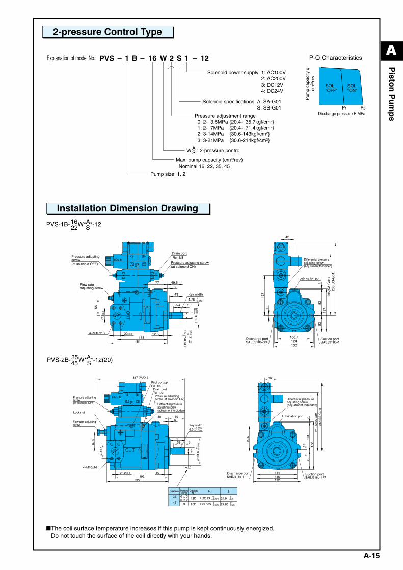
2-pressure Control Type
PVS-1B-16W*A*-1222 S
PVS-2B-35W*A*-12(20)45 S
❚The coil surface temperature increases if this pump is kept continuously energized.Do not touch the surface of the coil directly with your hands.
SOL b
NA
CH
I
Rc 3/8
4–M10x16
SAEJ518b-3/4
525.4
21.2
82.6
12.5158
22±0.2
47.5
±0.2
677
181
55
19.0
5
43
49.5
106.4
130
52
11
42
124
8213
73
127
0 –0.2
5
0 –0.0
21φ
–0.0
36–0
.071
φ
4.76 0–0.012
24φ
233(
SS
-G01
)19
5(S
A-G
01)
Pressure adjusting screw (at solenoid OFF)
Flow rate adjusting screw
Drain port
Pressure adjusting screw (at solenoid ON)
Key width
Discharge port Suction portSAEJ518b-1
Lubrication port
Differential pressure adjusting screw (adjustment forbidden)
SAEJ518b-11/4
Rc 1/4
NA
CH
I
SOL bRc 1/2
4–M10x16
144146172
6513
45
90.5 10
43
172
53338
606
1921526.2±0.2
52.4
±0.2
88
317 (MAX )
222
69.5
28φ
A B
101.
6–0
.051
0φ
6.3 +0.015–0.010
SAEJ518b-1
212.
5(S
A-G
01)
254(
SS
-G01
)
φ
φ
A Bcm3/rev
3
22.23 0–0.021
0–0.524.9
25.385 0–0.025
0–0.2527.85
12D
20D
35
45
Pressure Range
Design No.
Pressure adjusting screw (at solenoid OFF)
Lock nut
Flow rate adjusting screw
Pilot port pp
Drain port
Pressure adjusting screw (at solenoid ON)
Differential pressure adjusting screw (adjustment forbidden)
Key width
Differential pressure adjusting screw (adjustment forbidden)
Lubrication port
Discharge port Suction port
0 to 30 to 2
Pressure adjustment range 0: 2- 3.5MPa {20.4- 35.7kgf/cm2} 1: 2- 7MPa {20.4- 71.4kgf/cm2} 2: 3-14MPa {30.6-143kgf/cm2} 3: 3-21MPa {30.6-214kgf/cm2}
W : 2-pressure controlAS
Max. pump capacity (cm3/rev) Nominal 16, 22, 35, 45
Pump size 1, 2
1: AC100V2: AC200V3: DC12V4: DC24V
Solenoid power supply
A: SA-G01S: SS-G01
Solenoid specifications
122 1SW16B1– – –Explanation of model No.: PVS
Installation Dimension Drawing
SOL"ON"
SOL"OFF"
P1 P2
P-Q Characteristics
Discharge pressure P MPa
Pum
p ca
paci
ty q
cm
3 /re
v
A_Piston(P01-15)_E.q 03.11.20 0:46 PM Page 15
A
A-16
Hyd
raulic P
um
ps
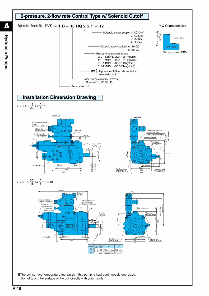
2-pressure, 2-flow rate Control Type w/ Solenoid Cutoff
PVS-1B-16RQ*A*-1222 S
PVS-2B-35RQ*A*-12(20)45 S
❚The coil surface temperature increases if this pump is kept continuously energized.Do not touch the surface of the coil directly with your hands.
SOL b
NA
CH
I
Rc 3/8
525.4
21.2
12.5158
22±0.2
47.5
±0.2
623
77
181 19.0
5
49.5
43
221
296(MAX)
106.4
130
52
11
124
8213
73
42
107.5(MAX)4–M10x16
24φ
0 –0.2
5
0 –0.0
21φ
82.6
–0.0
36–0
.071
φ
4.76 0–0.012
SAEJ518b-3/4 SAEJ518b-1
215(
SS
-G01
)
177(
SA
-G01
)
P2 pressure adjusting screw (at solenoid ON)
Drain portq1 flow rate adjusting screw
q2 flow rate adjusting screw
Key width
Differential pressureadjusting screw(adjustment forbidden)
Lubrication port
P1 pressure adjusting screw
Discharge port Suction port
SOL b
NA
CH
I
Rc 1/2
144146172
65
45
13
90.5
107.5(MAX)
104
317
253338
6
1921526.2±0.2
52.4
±0.2
88
222
352(MAX)
60
28φ
4–M10x16
A B
6.3 +0.015–0.010 19
4.5(
SA
-G01
)
236(
SS
-G01
)
SAEJ518b-11/4SAEJ518b-1
101.
6–0
.051
0φ
φ
φ
A Bcm3/rev
0 30 2
3
22.23 0–0.021
0–0.524.9
25.385 0–0.025
0–0.2527.85
12D
20D
35
45
Pressure Range
Design No.
Pressure adjusting screw (at solenoid ON)
q1 flow rate adjusting screw
q2 flow rate adjusting screw
Drain port
Key width
Lubrication port
P1 pressure adjusting screw
Discharge port Suction port
Differential pressure adjusting screw (adjustment forbidden)
Pressure adjustment range 0: 2- 3.5MPa {20.4- 35.7kgf/cm2} 1: 2- 7MPa {20.4- 71.4kgf/cm2} 2: 3-14MPa {30.6-143kgf/cm2} 3: 3-21MPa {30.6-214kgf/cm2}
RQ : 2-pressure, 2-flow rate control w/ solenoid cutoff
AS
Max. pump capacity (cm3/rev) Nominal 16, 22, 35, 45
Pump size 1, 2
1: AC100V2: AC200V3: DC12V4: DC24V
Solenoid power supply
A: SA-G01S: SS-G01
Solenoid specifications
122 1SRQ16B1– – –Explanation of model No.: PVS
Installation Dimension Drawing
SOL "ON"
SOL "OFF"
Discharge pressure P MPa
Pum
p ca
paci
ty q
cm
3 /re
v
P-Q Characteristics
A_Piston(P16-17)_E.q 03.11.20 0:45 PM Page 16
A
A-17
Hyd
raulic P
um
ps
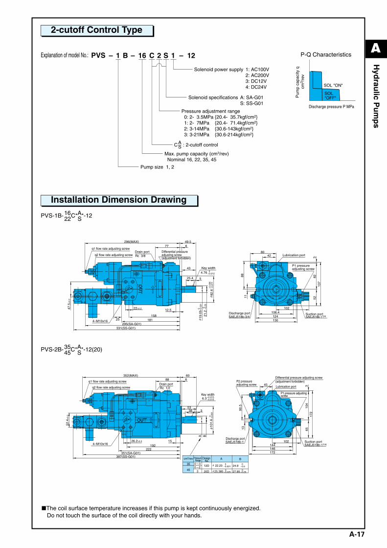
2-cutoff Control Type
PVS-1B-16C*A*-1222 S
PVS-2B-35C*A*-12(20)45 S
❚The coil surface temperature increases if this pump is kept continuously energized.Do not touch the surface of the coil directly with your hands.
NA
CH
I
Rc 3/8
4–M10x16
525.4
12.5
158
22±0.247.5
±0.2
677
181
49.5
43
331(SS-G01)
25295(SA-G01)
296(MAX)
106.4
130
5211
12482
137
342
88
80
102
4.76 0–0.012
21.2
19.0
50 –0.2
5
0 –0.0
21φ
82.6
–0.0
36–0
.071
φ
24
SAEJ518b-3/4 Suction port
q1 flow rate adjusting screw
q2 flow rate adjusting screwDrain port
Key width
Lubrication port
Discharge port
P1 pressure adjusting screw
SAEJ518b-11/4
φ
Differential pressure adjusting screw (adjustment forbidden)
NA
CH
I
Rc 1/2
4–M10x16 144146172
65
45
1390
.5
102
104
317
2
53338
6
1921526.2±0.2
52.4
±0.2
88
222
352(MAX) 60
351(SA-G01)387(SS-G01)
A B
SAEJ518b-11/4SAEJ518b-1
6.3 +0.015–0.010
101.
6–0
.051
0φ
28φ
φ
φ
A Bcm3/rev
0 30 2
3
22.23 0–0.021
0–0.524.9
25.385 0–0.025
0–0.2527.85
12D
20D
35
45
Pressure Range
Design No.
q1 flow rate adjusting screwDrain port
q2 flow rate adjusting screw
Key width
Differential pressure adjusting screw (adjustment forbidden)P2 pressure
adjusting screwLubrication port
P1 pressure adjusting screw
Discharge portSuction port
Pressure adjustment range 0: 2- 3.5MPa {20.4- 35.7kgf/cm2} 1: 2- 7MPa {20.4- 71.4kgf/cm2} 2: 3-14MPa {30.6-143kgf/cm2} 3: 3-21MPa {30.6-214kgf/cm2}
C : 2-cutoff controlAS
Max. pump capacity (cm3/rev) Nominal 16, 22, 35, 45
Pump size 1, 2
1: AC100V2: AC200V3: DC12V4: DC24V
Solenoid power supply
A: SA-G01S: SS-G01
Solenoid specifications
122 1SC16B1– – –Explanation of model No.: PVS
Installation Dimension Drawing
SOL "ON"
SOL"OFF"
Discharge pressure P MPa
Pum
p ca
paci
ty q
cm
3 /re
v
P-Q Characteristics
A_Piston(P16-17)_E.q 03.11.20 0:45 PM Page 17
A
A-18
Pisto
n P
um
ps
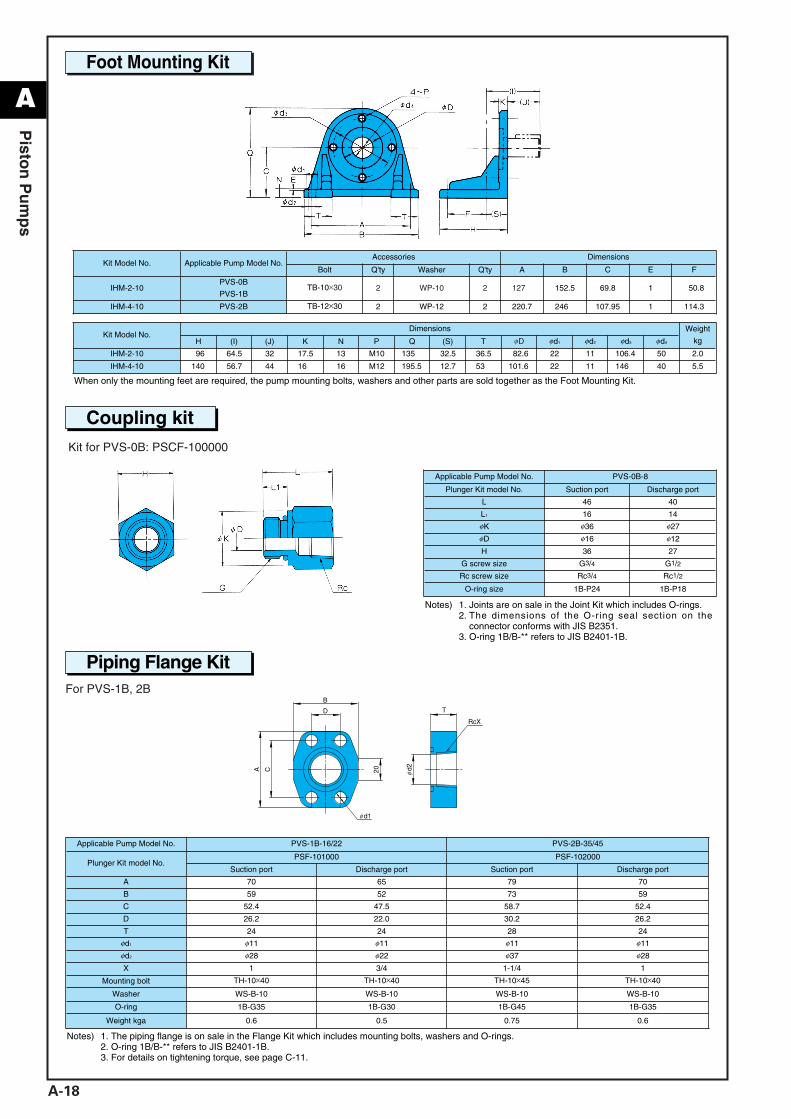
Foot Mounting Kit
Coupling kit
Piping Flange Kit
Kit for PVS-0B: PSCF-100000
For PVS-1B, 2B
Kit Model No. Applicable Pump Model No.Accessories Dimensions
Bolt Q'ty Washer Q'ty A B C E F
IHM-2-10PVS-0B
PVS-1BTB-10×30 2 WP-10 2 127.7 152.5 69.8 1 150.8
IHM-4-10 PVS-2B TB-12×30 2 WP-12 2 220.7 246.5 107.95 1 114.3
Kit Model No.Dimensions Weight
kgH (I) (J) K N P Q (S) T φD φd1 φd2 φd3 φd4
IHM-2-10 96 64.5 32 17.5 13 M10 135 32.5 36.5 82.6 22 11 106.4 50 2.0
IHM-4-10 140 56.7 44 16 16 M12 195.5 12.7 53 101.6 22 11 146 40 5.5
Applicable Pump Model No. PVS-0B-8
Plunger Kit model No. Suction port Discharge port
L 46 40
L1 16 14
φK φ36 φ27
φD φ16 φ12
H 36 27
G screw size G3/4 G1/2
Rc screw size Rc3/4 Rc1/2
O-ring size 1B-P24 1B-P18
When only the mounting feet are required, the pump mounting bolts, washers and other parts are sold together as the Foot Mounting Kit.
Notes) 1. Joints are on sale in the Joint Kit which includes O-rings.2. The dimensions of the O-ring seal section on the
connector conforms with JIS B2351.3. O-ring 1B/B-** refers to JIS B2401-1B.
Notes) 1. The piping flange is on sale in the Flange Kit which includes mounting bolts, washers and O-rings.2. O-ring 1B/B-** refers to JIS B2401-1B.3. For details on tightening torque, see page C-11.
Applicable Pump Model No. PVS-1B-16/22 PVS-2B-35/45
Plunger Kit model No.PSF-101000 PSF-102000
Suction port Discharge port Suction port Discharge port
A 70 65 79 70
B 59 52 73 59
C 52.4 47.5 58.7 52.4
D 26.2 22.0 30.2 26.2
T 24 24 28 24
φd1 φ11 φ11 φ11 φ11
φd2 φ28 φ22 φ37 φ28
X 1 3/4 1-1/4 1
Mounting bolt TH-10×40 TH-10×40 TH-10×45 TH-10×40
Washer WS-B-10 WS-B-10 WS-B-10 WS-B-10
O-ring 1B-G35 1B-G30 1B-G45 1B-G35
Weight kga 0.6 0.5 0.75 0.6
A_Piston(P18-21)_E.q 03.11.20 0:45 PM Page 18
A
A-19
Pisto
n P
um
ps
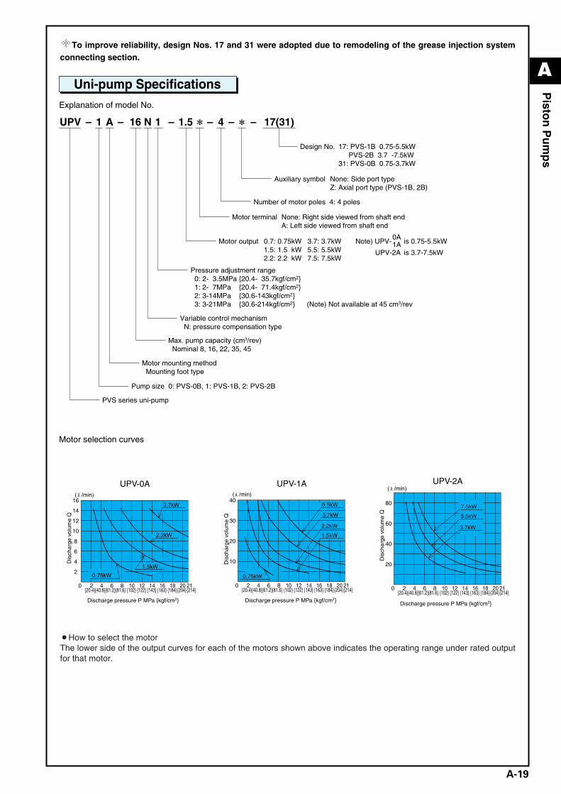
To improve reliability, design Nos. 17 and 31 were adopted due to remodeling of the grease injection systemconnecting section.
Uni-pump SpecificationsExplanation of model No.
Motor selection curves
¡How to select the motorThe lower side of the output curves for each of the motors shown above indicates the operating range under rated outputfor that motor.
UPV-0A
{204}20
{184}18
{163}16
{143}14
{122}{102}{81.6}12
4
6
16
8 10 212 4 60
2
{214}
( /min)
{20.4}{40.8}{61.2}
8
10
12
14
0.75kW
1.5kW
2.2kW
3.7kW
Dis
char
ge v
olum
e Q
Discharge pressure P MPa {kgf/cm2}
10
40
20
30
0.75kW
1.5kW
2.2kW
3.7kW
5.5kW
UPV-1A
{204}20
{184}18
{163}16
{143}14
{122}{102}{81.6}128 10 212 4 60
{214}{20.4}{40.8}{61.2}
( /min)
Dis
char
ge v
olum
e Q
Discharge pressure P MPa {kgf/cm2}
20
80
40
603.7kW
5.5kW
7.5kW
UPV-2A
{204}20
{184}18
{163}16
{143}14
{122}{102}{81.6}128 10 212 4 60
{214}{20.4}{40.8}{61.2}
( /min)
Dis
char
ge v
olum
e Q
Discharge pressure P MPa {kgf/cm2}
Design No. 17: PVS-1B 0.75-5.5kW PVS-2B 3.7 -7.5kW31: PVS-0B 0.75-3.7kW
Pressure adjustment range 0: 2- 3.5MPa {20.4- 35.7kgf/cm2} 1: 2- 7MPa {20.4- 71.4kgf/cm2} 2: 3-14MPa {30.6-143kgf/cm2} 3: 3-21MPa {30.6-214kgf/cm2} (Note) Not available at 45 cm3/rev
Variable control mechanism N: pressure compensation type
Max. pump capacity (cm3/rev) Nominal 8, 16, 22, 35, 45
Motor mounting method Mounting foot type
Pump size 0: PVS-0B, 1: PVS-1B, 2: PVS-2B
PVS series uni-pump
Number of motor poles 4: 4 poles
0.7: 0.75kW 3.7: 3.7kW1.5: 1.5 kW 5.5: 5.5kW2.2: 2.2 kW 7.5: 7.5kW
Motor output
Auxiliary symbol None: Side port typeZ: Axial port type (PVS-1B, 2B)
Motor terminal None: Right side viewed from shaft endA: Left side viewed from shaft end
Note) UPV-
UPV-2A
is 0.75-5.5kW
is 3.7-7.5kW
0A1A
41 1.5N16A1– – –– – 17(31)–UPV
A_Piston(P18-21)_E.q 03.11.20 0:45 PM Page 19
A
A-20
Pisto
n P
um
ps
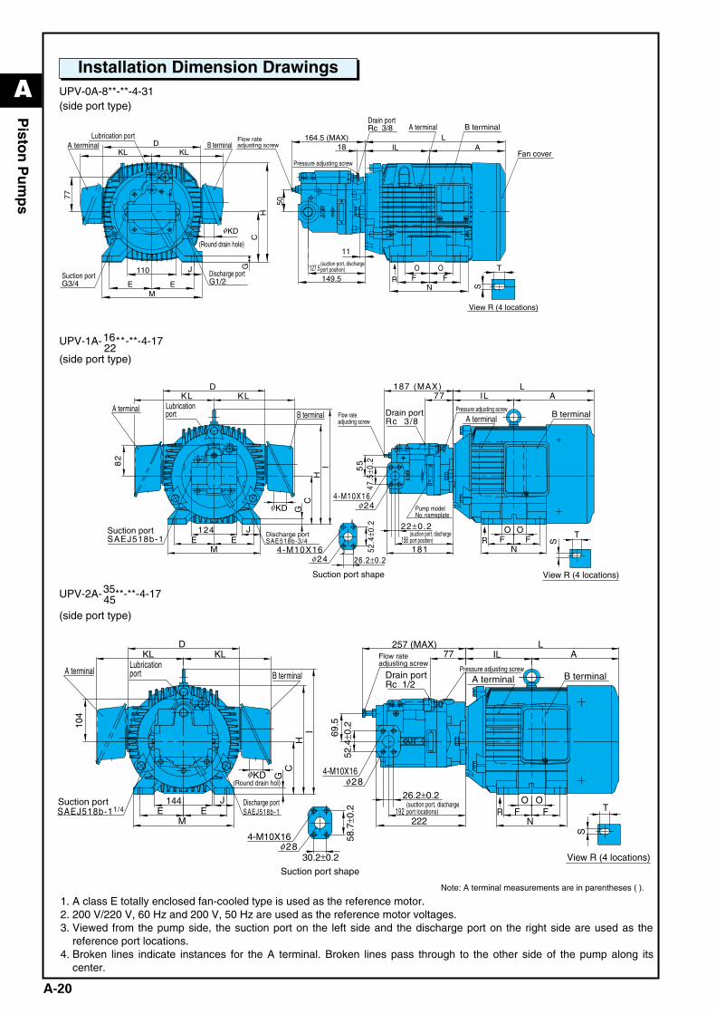
UPV-0A-8**-**-4-31(side port type)
UPV-1A-16**-**-4-1722
(side port type)
UPV-2A-35**-**-4-1745(side port type)
1. A class E totally enclosed fan-cooled type is used as the reference motor.2. 200 V/220 V, 60 Hz and 200 V, 50 Hz are used as the reference motor voltages.3. Viewed from the pump side, the suction port on the left side and the discharge port on the right side are used as the
reference port locations.4. Broken lines indicate instances for the A terminal. Broken lines pass through to the other side of the pump along its
center.
Note: A terminal measurements are in parentheses ( ).
(Round drain hole)
View R (4 locations)
R
Lubrication portB terminalA terminal
Discharge portG1/2
Suction portG3/4
Drain portRc 3/8 A terminal B terminal
Fan cover
110
77
ME E
GC
H
KD
KL KLD
J
11
164.5 (MAX)18
50
LIL A
O OFF
N
T
S
127.5149.5
φ
Flow rateadjusting screw
Pressure adjusting screw
(suction port, dischargeport position)
Suction port shape
R
View R (4 locations)
4-M10X16
Lubricationport B terminal
Suction portSAEJ518b-1
Discharge portSAE518b-3/4
B terminal
4-M10X16
Drain portRc 3/8
24
Pump modelNo. nameplate
A terminal
D
I82
124E E
M
J
CH
G
KL KL
52.4
±0.2
F
77 IL187 (MAX)
47.5
±0.2
55
26.2±0.2
O O
L
N181158 F
22±0.2T
S
A
KDφ
φ
24φ
Flow rateadjusting screw
Pressure adjusting screwA terminal
(suction port, dischargeport position)
View R (4 locations)
Suction port shape
Suction port Discharge portSAEJ518b-1
B terminal
Flow rateadjusting screw
Drain portRc 1/2
B terminal
4-M10X16
4-M10X16
A terminalA terminal
Lubricationport
58.7
±0.2
30.2±0.2
26.2±0.2
69.5
144F
KL
G
L
O
N
O
222
A
JE
104
C
M
52.4
±0.2
H
S
77
TF
257 (MAX)IL
E
I
DKL
192
28φ
SAEJ518b-11/4
28φ
(Round drain hol)KDφ
R(suction port, dischargeport locations)
Pressure adjusting screw
Installation Dimension Drawings
A_Piston(P18-21)_E.q 03.11.20 0:45 PM Page 20
A
A-21
Pisto
n P
um
ps
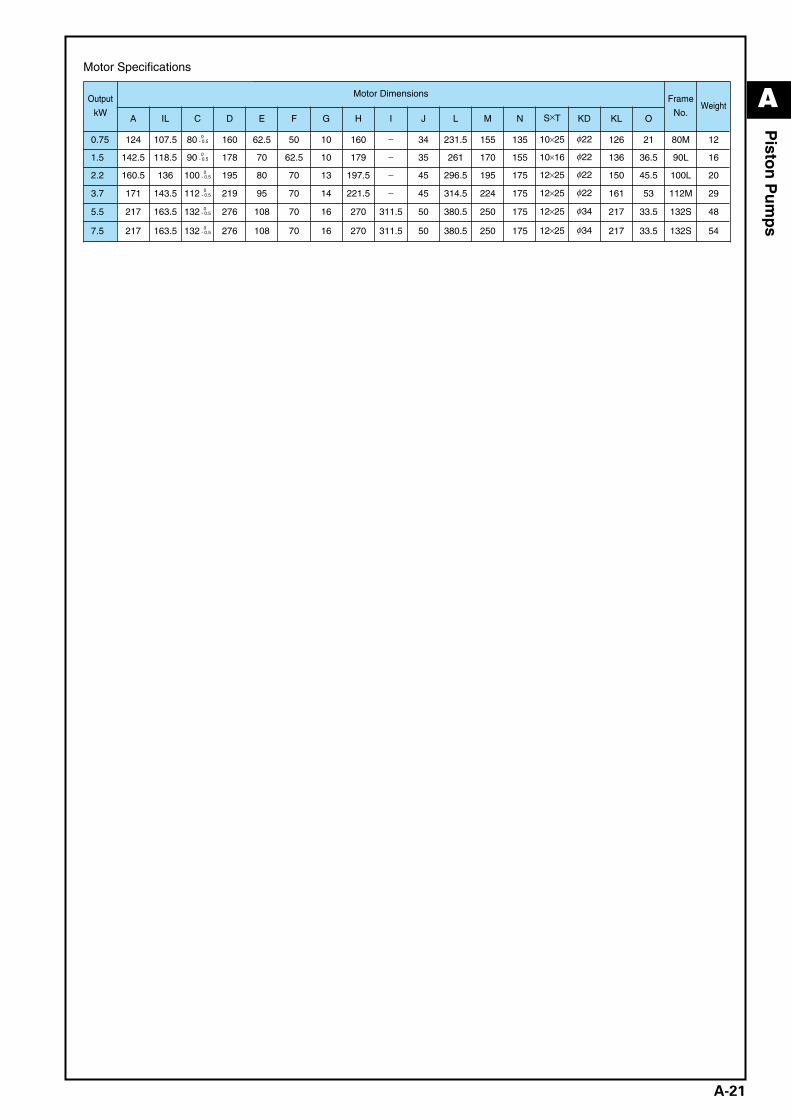
Output
kW
Motor Dimensions Frame
No.Weight
A IL C D E F G H I J L M N S×T KD KL O
0.75 124 107.5 80 0- 0.5 160 62.5 50 10 160 − 34 231.5 155 135 10×25 φ22 126 21 80M 12
1.5 142.5 118.5 90 0- 0.5 178 70 62.5 10 179 − 35 261 170 155 10×16 φ22 136 36.5 90L 16
2.2 160.5 136 100 0- 0.5 195 80 70 13 197.5 − 45 296.5 195 175 12×25 φ22 150 45.5 100L 20
3.7 171 143.5 112 0- 0.5 219 95 70 14 221.5 − 45 314.5 224 175 12×25 φ22 161 53 112M 29
5.5 217 163.5 132 0- 0.5 276 108 70 16 270 311.5 50 380.5 250 175 12×25 φ34 217 33.5 132S 48
7.5 217 163.5 132 0- 0.5 276 108 70 16 270 311.5 50 380.5 250 175 12×25 φ34 217 33.5 132S 54
Motor Specifications
A_Piston(P18-21)_E.q 03.11.20 0:45 PM Page 21