Embed Size (px)
Citation preview
97-600100-15-A03
PVM1010 Inverter Data Monitoring Module
INSTALLATION MANUAL


i
PV PoweredPV Powered designs, manufactures, and markets the solar power industry’s most reliable photovoltaic solar inverter solutions. We’ve assembled a highly experienced solar power electronics design team. Our vision is to spur the widespread adoption and success of solar power, by assisting our distributors, dealers and installers in this dynamic market while ensuring that our products are the best supported, easiest to install, and most reliable solar inverters in the industry. Our innovative approach to performance monitoring provides secure and easy access to system performance and inverter status over the Internet.
Contact InformationPV Powered, Inc. PO Box 7348 Bend, OR 97708
Tel: 541-312-3832 Technical Support: 1-877-312-3832 Fax: 541-383-2348
www.pvpowered.com email: [email protected]
Document CopyrightPV Powered PVM1010 Inverter Data Monitoring Module Installation Manual ©2009 PV Powered. All rights reserved. This manual may not be reproduced or distributed without written permission from PV Powered.
PREFAC
E
Preface

ii
iii
Table of Contents
PVM1010 Installation ...................................................... 11.1 Important Safety Instructions ............................. 11.2 Installation Requirements ................................... 11.3 Internet Connection Requirements ..................... 21.4 Installing and Connecting the PVM1010 ........... 31.5 Installation Checklist .......................................... 71.6 Troubleshooting .................................................. 7
TABLE of CO
NTEN
TS

iv
List of Figures and TablesTable 1-1 RJ45 Wiring schematic .....................................2Figure 1-1 T-568B Compliant CAT5 cable .........................2Figure 1-2 Inverter’s power board and knockouts ..............3Figure 1-3 Connecting the ground cable to the inverter’s
power board .......................................................4Figure 1-4 PVM1010 inserted to the inverter’s power
board ..................................................................4Figure 1-5 Securing the PVM1010 with two screws ..........5Figure 1-6 Plugging in the power cable to the inverter’s
power board .......................................................5Figure 1-7 Plugging the power cable to the PVM1010’s J3
slot .....................................................................6Figure 1-8 Cord grip ...........................................................6Figure 1-9 Connecting the CAT5 cable to the PVM1010’s
RJ45 port ...........................................................6

1
1.1 Important Safety InstructionsPlease read all safety warnings and instructions before beginning the installation of the PVM1010 Inverter Data Monitoring Module. This product has been engineered and manufactured to ensure your personal safety. Improper use may result in potential electrical shock or burns.
The PVM1010 should only be installed by a licensed electrician or qualified solar electric installer. Do not attempt to install this device if you have not been properly trained. If you have any questions, please contact PV Powered Technical Services and Support at 541-312-3832.
!CAUTION
Before connecting the PVM1010 to the PV Powered inverter, make sure that both AC and DC power to the inverter are turned OFF. After turning off the power, wait five minutes before removing the front cover from the inverter.
SUPPORT: Before contacting Technical Services and Support, please refer to the Troubleshooting section of this Installation Manual. For networking issues, contact customer support for your router vendor or internet provider. For other unresolved issues, contact PV Powered Technical Services and Support at 541-312-3832.
1.2 Installation Requirements
PVM1010 Product PackagePV Powered provides the following items in your PVM1010 product package:
• PVM1010 Data Monitoring Module
• Power cable
• Cord grip
• Screws
• Installation manual
Inverters Supported by the PVM1010 ModuleYou need one or more of the following (pre-installed) PVM1010-supported inverters: PVP1100, PVP2000, PVP2500, PVP3000, PVP3500, PVP4800, PVP4600, PVP5200
Required Tools and MaterialsBring the following items to perform the installation (NOT provided by PV Powered):
• Linksys, Netgear, D-link or other broadband router
• Laptop or Netbook – to verify communication to the PVM1010
PVM1010
INSTA
LLATION
PVM1010 Installation
2
• CAT5 cable – to make the connection between the router and the PVM1010
• RJ45 crimping tool
• RJ45 connectors
• Phillips screwdriver
• Digital multimeter – used to test the PVM1010’s voltage supply (optional)
• Cable tester – used to test CAT5 cables (recommend the Fluke networks MicroMapper)
1.3 Internet Connection RequirementsThe PVM1010 will not work until it is connected using an always ON, high-speed broadband connection such as DSL or cable.
• Customers must have Ethernet available at the inverter location. The PVM1010 does NOT support modem connectivity.
• The PVM1010 only supports hard-wired communications to the inverter. The PVM1010 does NOT support wireless communications.
Making a CAT5 CableTo make a new CAT5 cable, you need the following:
• RJ45 crimping tool
• RJ45 connectors
• CAT5 cable
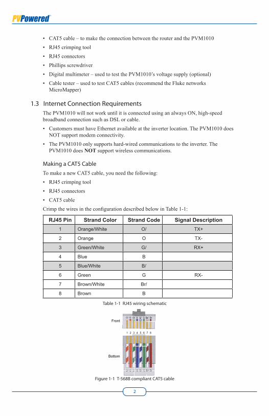
Crimp the wires in the configuration described below in Table 1-1:
RJ45 Pin Strand Color Strand Code Signal Description1 Orange/White O/ TX+
2 Orange O TX-
3 Green/White G/ RX+
4 Blue B
5 Blue/White B/
6 Green G RX-
7 Brown/White Br/
8 Brown B
Table 1-1 RJ45 wiring schematic
Figure 1-1 T-568B compliant CAT5 cable
1 2 3 4 5 6 7 8
Front
Bottom
PV Powered PVM1010 Inverter Data Monitoring Module Installation Manual
3
IMPORTANT: This wiring configuration complies with T-568B standards. This is the only wiring configuration supported by the PVM1010. Any other configuration is not reliable.After you make the CAT5 cable, use a cable tester to verify that your new cable works. The cable tester does not test wire order.
Next you need to complete the steps in the following section to install the PVM1010 before you can verify that data is successfully communicating over the cable.
1.4 Installing and Connecting the PVM1010
Installing the PVM10101. Turn OFF AC and DC power to the inverter. Wait five minutes before removing the
front cover and installing the PVM1010.
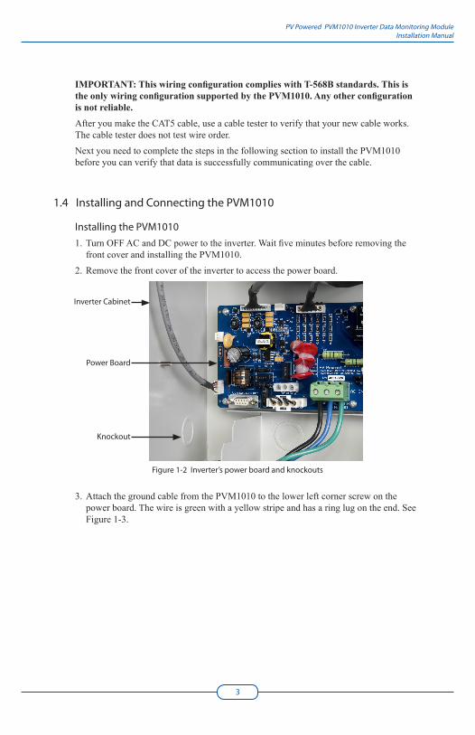
2. Remove the front cover of the inverter to access the power board.
Figure 1-2 Inverter’s power board and knockouts
3. Attach the ground cable from the PVM1010 to the lower left corner screw on the power board. The wire is green with a yellow stripe and has a ring lug on the end. See Figure 1-3.
Inverter Cabinet
Power Board
Knockout
4
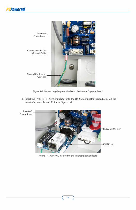
Figure 1-3 Connecting the ground cable to the inverter’s power board
4. Insert the PVM1010 DB-9 connector into the RS232 connector located at J3 on the inverter’s power board. Refer to Figure 1-4.
Figure 1-4 PVM1010 inserted to the inverter’s power board
Inverter’s Power Board
Ground Cable from PVM1010
Connection for the Ground Cable
Inverter’s Power Board
RS232 Connector
PVM1010
PV Powered PVM1010 Inverter Data Monitoring Module Installation Manual
5
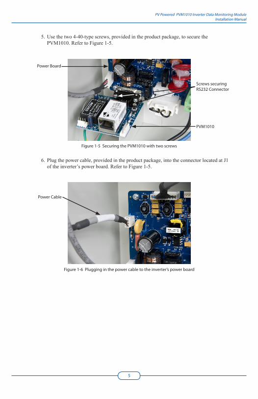
5. Use the two 4-40-type screws, provided in the product package, to secure the PVM1010. Refer to Figure 1-5.
Figure 1-5 Securing the PVM1010 with two screws
6. Plug the power cable, provided in the product package, into the connector located at J1 of the inverter’s power board. Refer to Figure 1-5.
Figure 1-6 Plugging in the power cable to the inverter’s power board
Power Cable
Power Board
Screws securing RS232 Connector
PVM1010
6
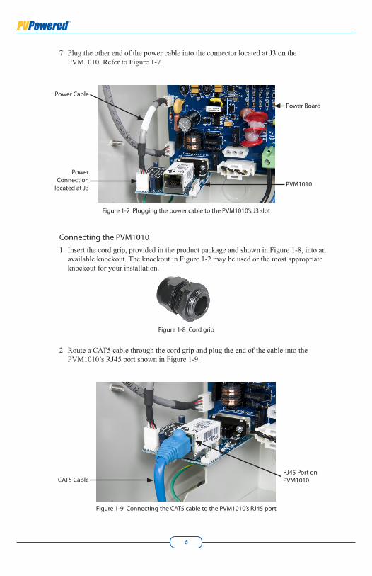
7. Plug the other end of the power cable into the connector located at J3 on the PVM1010. Refer to Figure 1-7.
Figure 1-7 Plugging the power cable to the PVM1010’s J3 slot
Connecting the PVM10101. Insert the cord grip, provided in the product package and shown in Figure 1-8, into an
available knockout. The knockout in Figure 1-2 may be used or the most appropriate knockout for your installation.
Figure 1-8 Cord grip
2. Route a CAT5 cable through the cord grip and plug the end of the cable into the PVM1010’s RJ45 port shown in Figure 1-9.
Figure 1-9 Connecting the CAT5 cable to the PVM1010’s RJ45 port
Power Cable
Power Connection
located at J3
RJ45 Port on PVM1010CAT5 Cable
Power Board
PVM1010

PV Powered PVM1010 Inverter Data Monitoring Module Installation Manual
7
3. After you attach the CAT5 cable to the PVM1010, tighten the grommet on the cord grip.
4. Connect the other end of the CAT5 cable to an Ethernet router, switch, or hub with access to high-speed internet.
CONGRATULATIONS! The PVM1010 is now installed and hooked up to the inverter and the internet.
1.5 Installation Checklist1. Turn ON (re-start) the AC and DC power to the inverter.
2. Wait two to three minutes.
3. Observe the LED lights on the PVM1010. They are located next to the Ethernet port.
The amber LED: Displays continuously (solid ON). If the amber light does not illuminate, there is a problem with the cables. Check the cables and make sure all routers and switches are ON.
The green LED: Flashes intermittently when data is transmitting.
The blue LED: This troubleshooting light flashes during boot up and then displays continuously (solid ON). It should begin to display approximately 45 seconds after you re-start power to the inverter. This light is located between the reset button and the six-pin connector.
4. If any of the lights do not display properly, refer to the Troubleshooting section of this manual.
The blue LED troubleshooting light displays blink codes that indicate issues requiring your attention. If this light is blinking after boot up, refer to the Troubleshooting section of this manual.
5. Before you complete the installation, write down the inverter’s serial number. This number is required to register the PVM1010.
6. Re-attach the front cover to the inverter.
7. Data will begin to display on the website approximately two to three minutes after the PVM1010 is powered up.
8. To register, log in at www.mypvpower.com and follow the registration process.
If a 3rd party data monitoring solution was provided with your system or you are planning to use a 3rd party provider, refer to the instructions provided by the 3rd party data monitoring provider.
1.6 TroubleshootingOne or more of the following indicators might communicate a problem:
• The blue LED light on the PVM1010 is blinking.
• The amber light on the PVM1010 is NOT continuously ON.
• The green light on the PVM1010 is continuously ON for an extended period of time (instead of flickering intermittently during transmissions).
• The data monitoring website does not display inverter data.
When there’s a problem, the blue LED initially displays three blinks in a row, followed by a long pause. Start interpreting the blink codes after the pause.
8
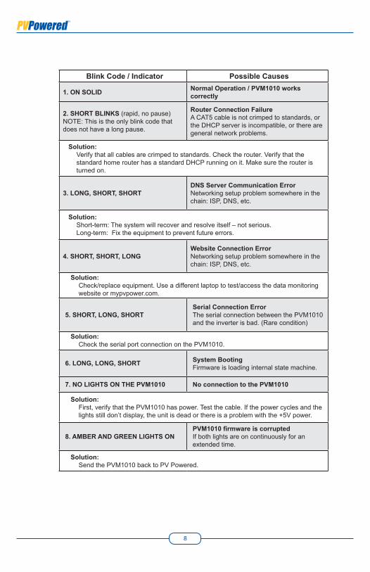
Blink Code / Indicator Possible Causes
1. ON SOLID Normal Operation / PVM1010 works correctly
2. SHORT BLINKS (rapid, no pause)NOTE: This is the only blink code that does not have a long pause.
Router Connection FailureA CAT5 cable is not crimped to standards, or the DHCP server is incompatible, or there are general network problems.
Solution: Verify that all cables are crimped to standards. Check the router. Verify that the standard home router has a standard DHCP running on it. Make sure the router is turned on.
3. LONG, SHORT, SHORTDNS Server Communication ErrorNetworking setup problem somewhere in the chain: ISP, DNS, etc.
Solution:Short-term: The system will recover and resolve itself – not serious. Long-term: Fix the equipment to prevent future errors.
4. SHORT, SHORT, LONGWebsite Connection ErrorNetworking setup problem somewhere in the chain: ISP, DNS, etc.
Solution: Check/replace equipment. Use a different laptop to test/access the data monitoring website or mypvpower.com.
5. SHORT, LONG, SHORTSerial Connection ErrorThe serial connection between the PVM1010 and the inverter is bad. (Rare condition)
Solution: Check the serial port connection on the PVM1010.
6. LONG, LONG, SHORT System BootingFirmware is loading internal state machine.
7. NO LIGHTS ON THE PVM1010 No connection to the PVM1010
Solution:First, verify that the PVM1010 has power. Test the cable. If the power cycles and the lights still don’t display, the unit is dead or there is a problem with the +5V power.
8. AMBER AND GREEN LIGHTS ONPVM1010 firmware is corruptedIf both lights are on continuously for an extended time.
Solution:Send the PVM1010 back to PV Powered.


PO Box 7348 • Bend, OR 97708 • P: 541-312-3832 • www.pvpowered.com