Embed Size (px)
Citation preview
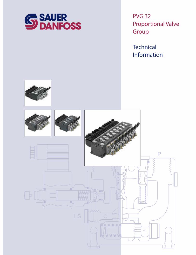
PVG 32
Proportional Valve
Group
Technical
Information
2 520L0344
PVG 32 Proportional Valve Group
Technical Information
Table of revisions
Date Page Changed Rev
69 GD
New back cover GE
All Major update
Revision History
Literature Reference
Literature reference for PVG products
Title Type Order number
Technical Information
Technical Information
Technical Information
Technical Information
FunctionTechnical Information
Technical Information
Technical Information
Technical Information
PVPV / PVPVM Pump Side Module Technical Information
Technical Information
Combination Module PVGI Technical Information
Technical Information
PVG 32 Metric port, 11051935 and Basic module PVBZ, 520L0721.
3520L0344
PVG 32 Proportional Valve Group
Technical Information
General Information
Function
Technical Data
6
6
6
6
6
8
8
8
9
PVG 32 Sectional View
PVPC with check valve for open center PVP
22
22
22
23
Principle
Application
26
PVG 32
28
28
PVE Technical Data 29
32
4 520L0344
PVG 32 Proportional Valve Group
Technical Information
Electrical Actuation
Modules and Code
Numbers
Technical Characteristics
Electrical control of PVG 33
36
PVEM 36
PVEP
38
39
General
5520L0344
PVG 32 Proportional Valve Group
Technical Information
Dimensions
Hydraulic Systems
Other Operating
Conditions
Module Selection Chart
Order Speci"cation
62
Surface Treatment
66
Filtration 68
69
82
6 520L0344
PVG 32 Proportional Valve Group
Technical Information
–
–
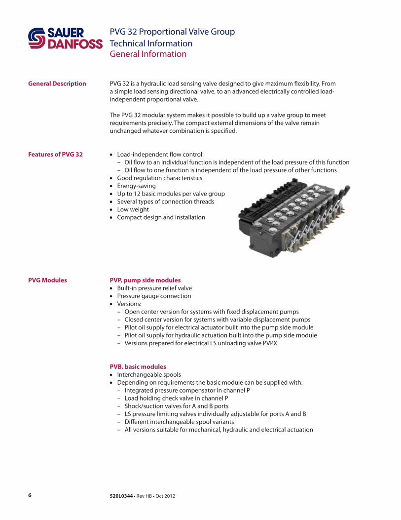
General Description
General Information
PVP, pump side modules
–
–
–
–
–
PVB, basic modules
–
–
–
–
–
–
Features of PVG 32
PVG Modules
7520L0344
PVG 32 Proportional Valve Group
Technical InformationGeneral Information
PVG Modules (continued) Actuation modules
__
–
–
–
–
–
–
–
–
–
–
–
Remote control units
–
–
–
–
–
–
–
–
–
–
–
–
Accessories
8 520L0344
PVG 32 Proportional Valve Group
Technical InformationGeneral Information
FMEA (Failure Mode and E#ect Analysis) IEC EN 61508
Hazard and Risk Analysis ISO 12100-1 / 14121
W
Safety in Application
9520L0344
PVG 32 Proportional Valve Group
Technical InformationGeneral Information
SupplyControl
NeutralDetection
Signal Conditioning
FailureDetection
FaultMonitoring
PVE fault output
SignalConditioning
SupplyMain controller
Hydraulic deactivation
HMI / Joystick
ControlSignal
Emergency stop andMan present switch
Motion detection sensor
PVE
Main control valve
Main power supply(battery)
Joystick neutral switch
P301 317
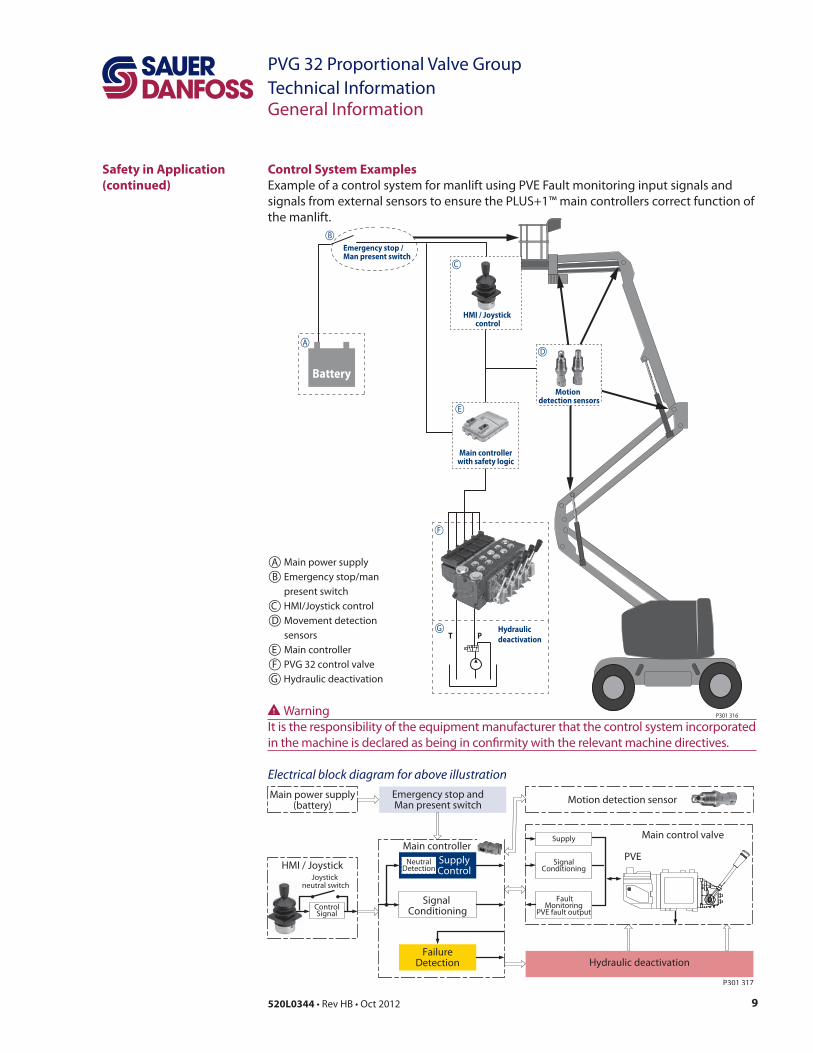
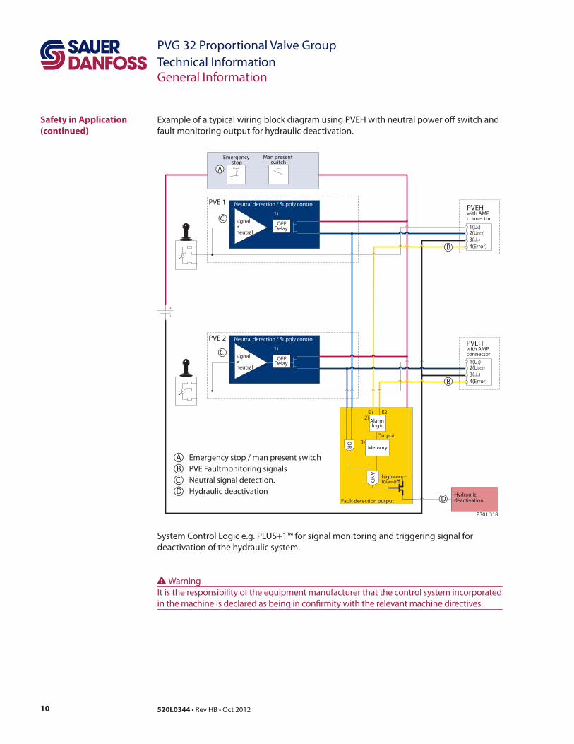
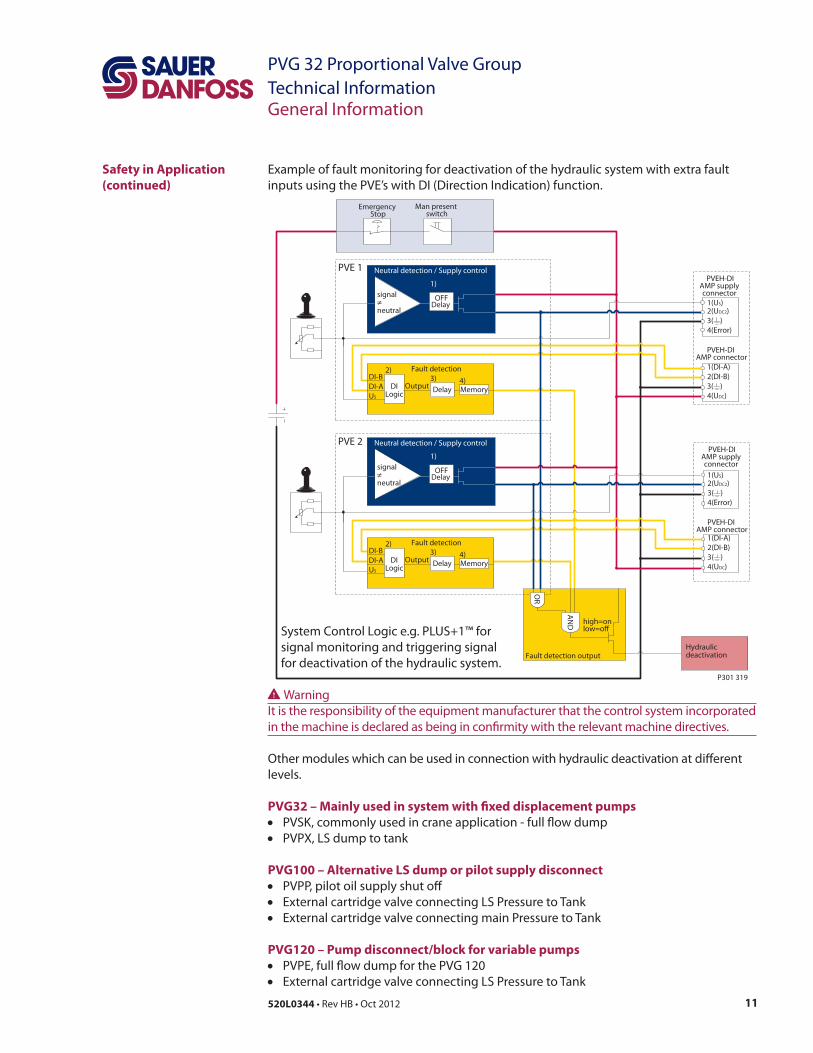
Safety in Application
(continued)
Control System Examples
Electrical block diagram for above illustration
Emergency stop / Man present switch
T P
Battery
Motiondetection sensors
Main controller with safety logic
Hydraulic
deactivation
HMI / Joystick control
A
B
C
D
E
F
G
P301 316
A B
C D Movement detection
E Main controller
F PVG 32 control valve
G
W
10 520L0344
PVG 32 Proportional Valve Group
Technical InformationGeneral Information
Fault detection output
high=onlow=o"
Alarm logic
2)
Memory3)
E1 E2
Output
AN
D
OR
Neutral detection / Supply control
signal≠neutral
OFFDelay
1)
2(UDC2)
3( )
4(Error)
1(US)
PVEH with AMP connector
2(UDC2)
3( )
4(Error)
1(US)
PVEHwith AMP connector
Hydraulicdeactivation
Neutral detection / Supply control
signal≠neutral
OFFDelay
1)
PVE 1
PVE 2
Emergency stop
Man present switch
C
C
D
B
B
A
P301 318
ABCD
W
Safety in Application
(continued)
11520L0344
PVG 32 Proportional Valve Group
Technical InformationGeneral Information
Neutral detection / Supply control
signal≠neutral
OFFDelay
1)
Fault detection output
2(UDC2)
3( )
4(Error)
1(US)
2(DI-B)
3( )
1(DI-A)
PVEH-DI AMP connector
4(UDC)
PVEH-DIAMP supply connector
2(UDC2)
3( )
4(Error)
1(US)
2(DI-B)
3( )
1(DI-A)
PVEH-DI AMP connector
4(UDC)
PVEH-DIAMP supply connector
AN
D
Hydraulicdeactivation
high=onlow=o#
Neutral detection / Supply control
signal≠neutral
OFFDelay
1)
PVE 1
PVE 2
Fault detection
DelayDILogic
MemoryUS
DI-A
DI-B2)
4)3)Output
Fault detection
DelayDILogic
MemoryUS
DI-A
DI-B2)
4)3)Output
OR
Emergency Stop
Man present switch
P301 319
PVG32 – Mainly used in system with "xed displacement pumps
PVG100 – Alternative LS dump or pilot supply disconnect
PVG120 – Pump disconnect/block for variable pumps
W
Safety in Application
(continued)
12 520L0344
PVG 32 Proportional Valve Group
Technical InformationGeneral Information
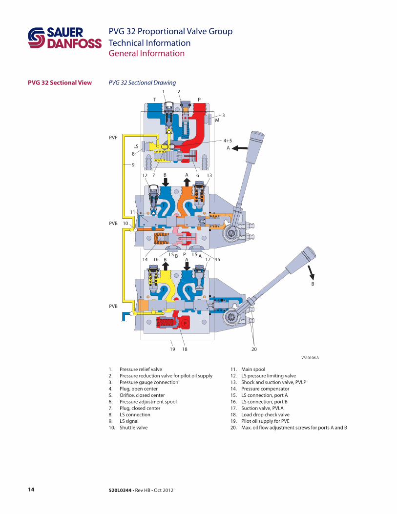
The sectional drawing V310106.A
PVG 32 with Open Center
PVP ("xed displacement
Control Spool
13520L0344
PVG 32 Proportional Valve Group
Technical InformationGeneral Information
PVG 32 with Closed
Center PVP (variable
PVB with Flow Control
Spool
14 520L0344
PVG 32 Proportional Valve Group
Technical InformationGeneral Information
PVG 32 Sectional View PVG 32 Sectional Drawing
1 2
3
4+5
67
9
8
T P
M
ALS
B A12 13
11
10
14 16 17 15
T T
LS B LS AB A
P
T T
B
19
P
18 20
V310106.A
PVP
15520L0344
PVG 32 Proportional Valve Group
Technical InformationGeneral Information
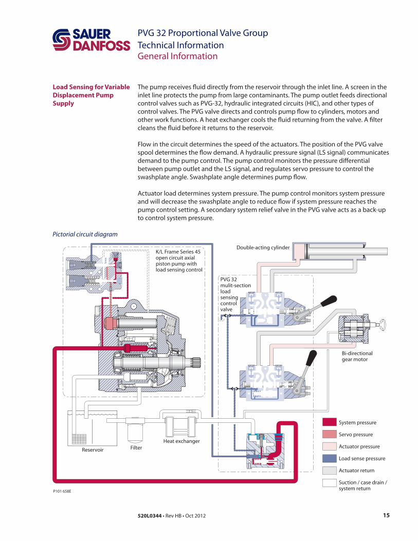
Load Sensing for Variable
Displacement Pump
Supply
Pictorial circuit diagram
System pressure
Servo pressure
Actuator pressure
Load sense pressure
Actuator return
Suction / case drain /system return
K/L Frame Series 45open circuit axialpiston pump withload sensing control
PVG 32mulit-sectionloadsensingcontrolvalve
P101 658E
Reservoir Filter
Heat exchanger
Double-acting cylinder
Bi-directionalgear motor
16 520L0344
PVG 32 Proportional Valve Group
Technical Information
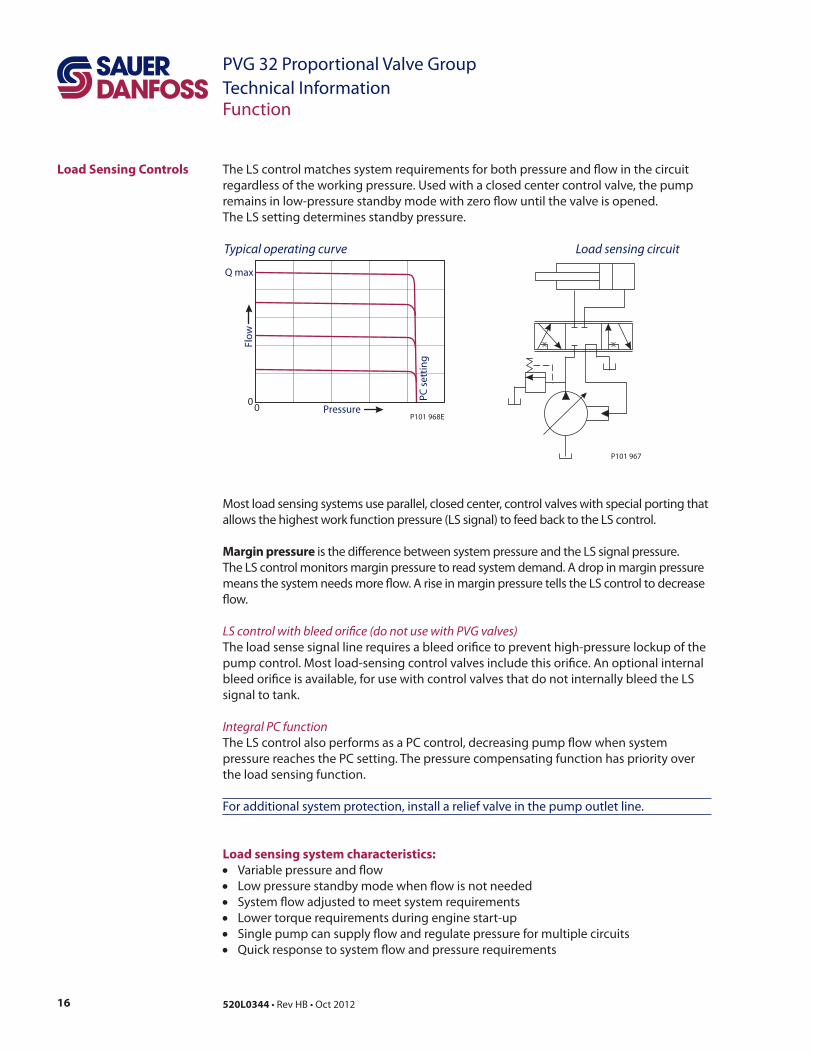
Load Sensing Controls
P101 967
Load sensing circuit
Margin pressure
LS control with bleed ori"ce (do not use with PVG valves)
Integral PC function
Load sensing system characteristics:
Variable pressure and flow
Low pressure standby mode when flow is not needed
System flow adjusted to meet system requirements
Lower torque requirements during engine start-up
Single pump can supply flow and regulate pressure for multiple circuits
Quick response to system flow and pressure requirements
00
P101 968EP
C s
ett
ing
Flo
w
Pressure
Q max
Typical operating curve
Function
17520L0344
PVG 32 Proportional Valve Group
Technical InformationFunction
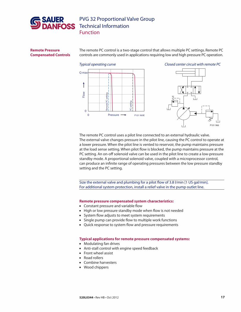
Remote Pressure
Compensated Controls
The remote PC control is a two-stage control that allows multiple PC settings. Remote PC
controls are commonly used in applications requiring low and high pressure PC operation.
P101 966
Closed center circuit with remote PC
Remote pressure compensated system characteristics:
Typical applications for remote pressure compensated systems:
0
0
Q max
Pressure
Flo
w
P101 969E
PC
se
ttin
g
Re
mo
te P
C s
ett
ing
Typical operating curve
18 520L0344
PVG 32 Proportional Valve Group
Technical InformationFunction
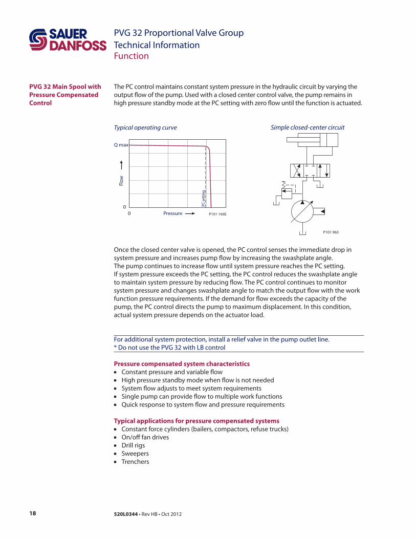
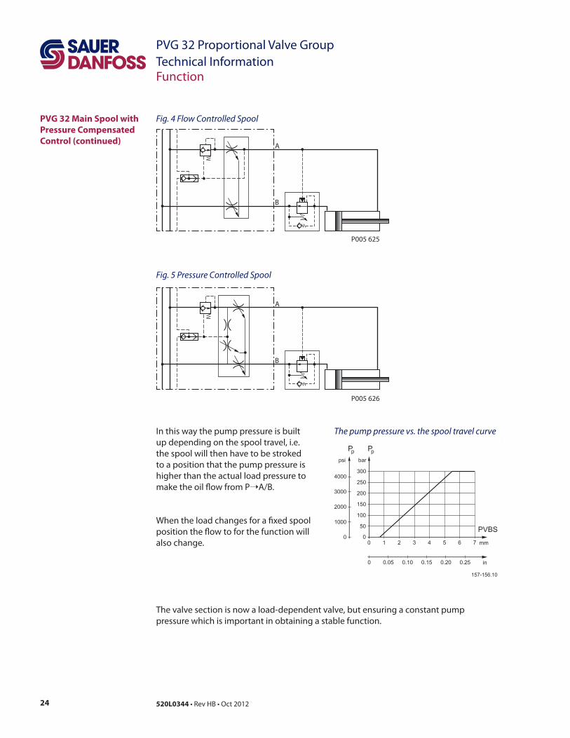
PVG 32 Main Spool with
Pressure Compensated
Control
P101 965
Simple closed-center circuit
0
0
Q max
Pressure
Flo
w
P101 166E
PC
se
ttin
g
Typical operating curve
Pressure compensated system characteristics
Typical applications for pressure compensated systems
19520L0344
PVG 32 Proportional Valve Group
Technical InformationFunction
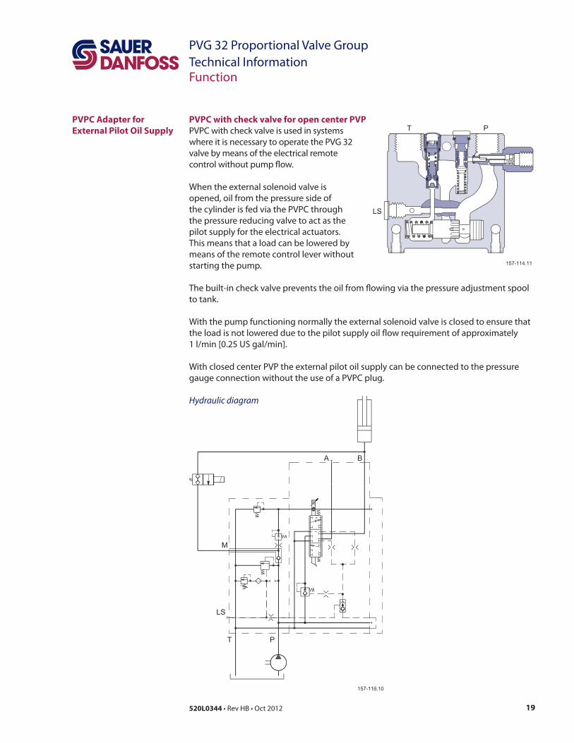
PVPC Adapter for
External Pilot Oil Supply
PVPC with check valve for open center PVP
Hydraulic diagram
20 520L0344
PVG 32 Proportional Valve Group
Technical InformationFunction
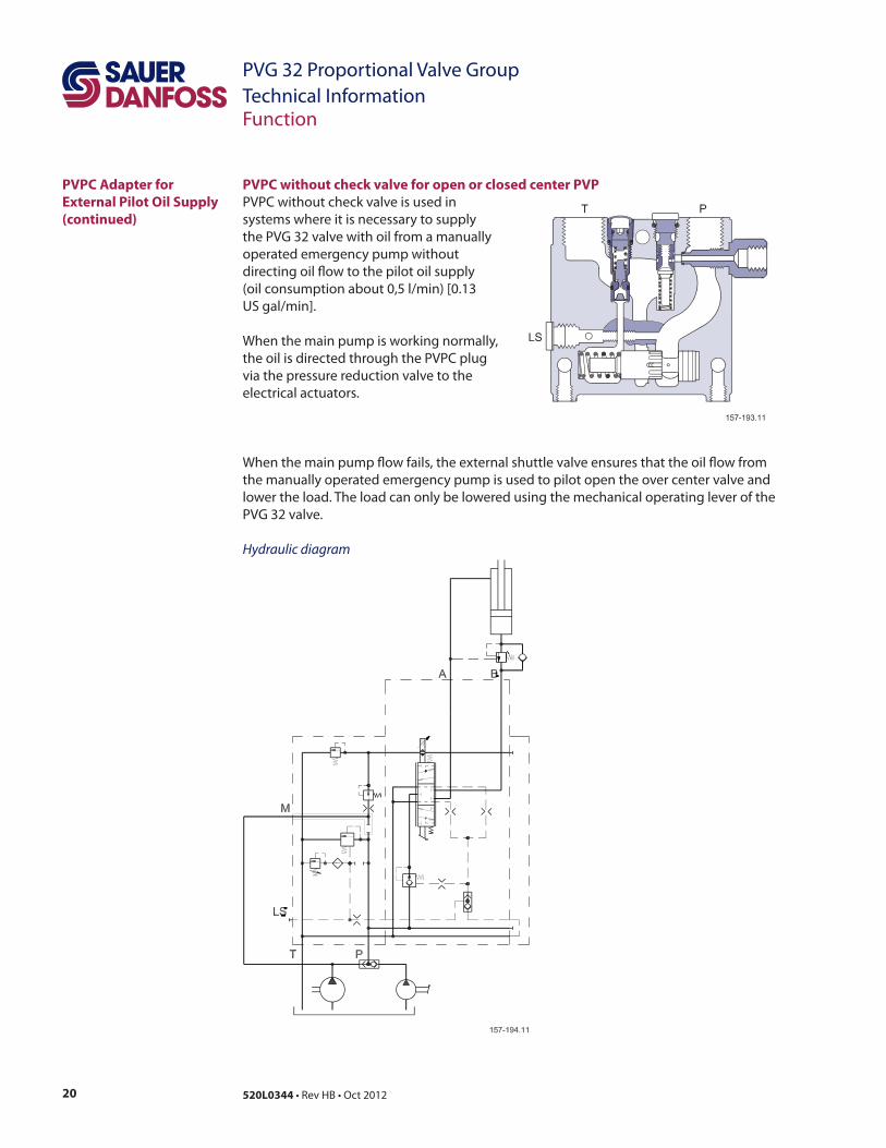
PVPC Adapter for
External Pilot Oil Supply
(continued)
PVPC without check valve for open or closed center PVP
Hydraulic diagram
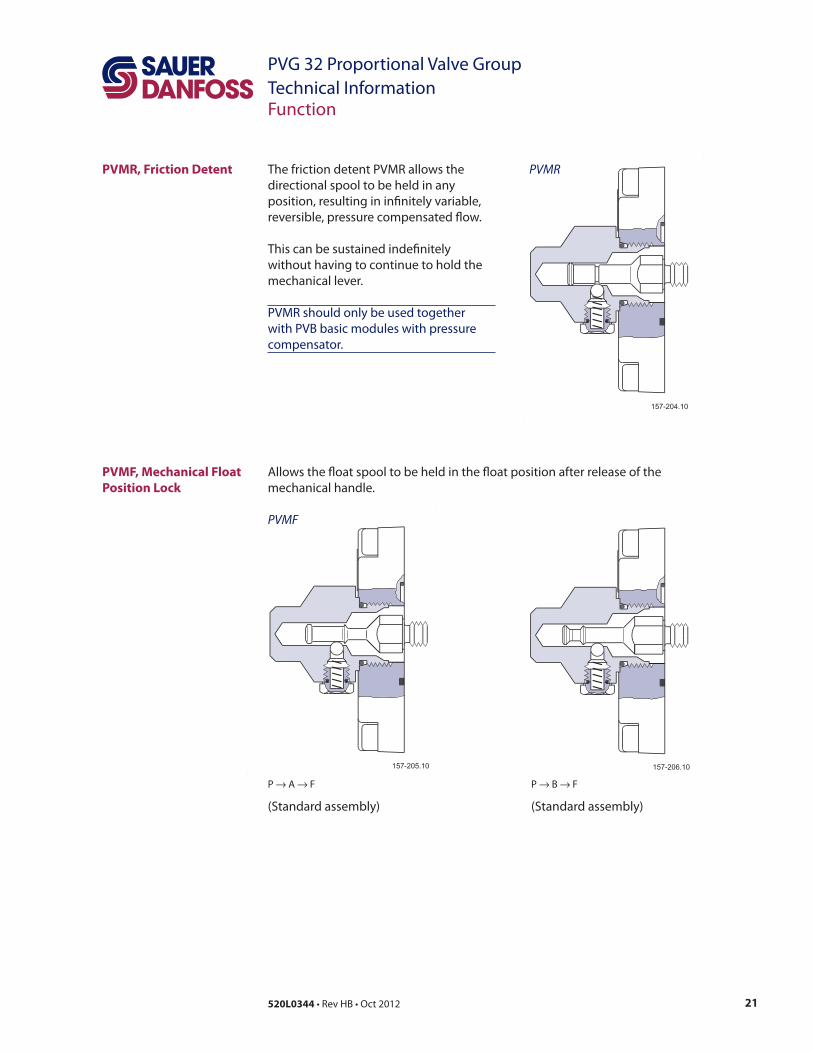
21520L0344
PVG 32 Proportional Valve Group
Technical InformationFunction
PVMRPVMR, Friction Detent
PVMF, Mechanical Float
Position Lock
P → A → F
PVMF
P → → F
22 520L0344
PVG 32 Proportional Valve Group
Technical InformationFunction
PVBS, Main Spools for
Flow Control (Standard)
PVBS, Main Spools for
Pressure Control
PVBS, Main Spools
for Flow Control (with
Linear Characteristic)
23520L0344
PVG 32 Proportional Valve Group
Technical InformationFunction
PVG 32 Main Spool
with Pressure Control
(continued)
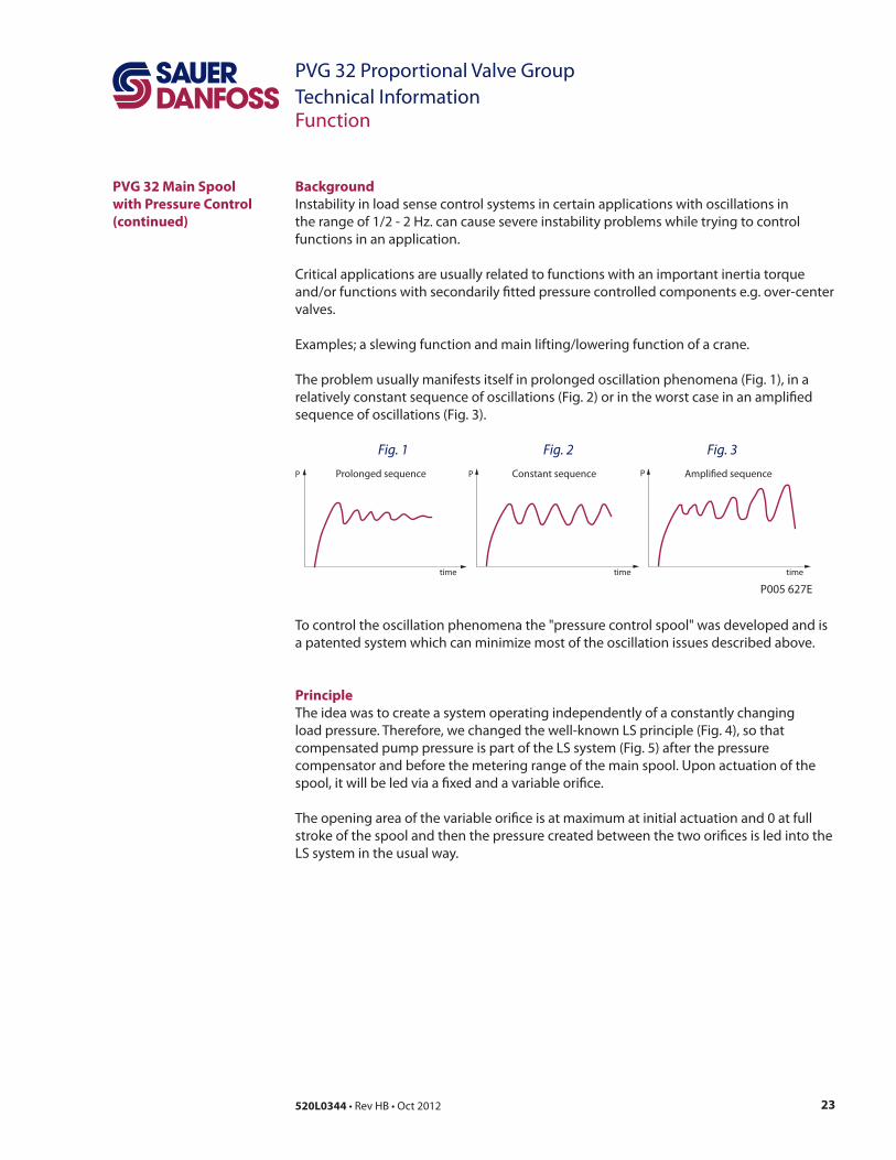
Background
Fig. 1 Fig. 2 Fig. 3
Principle
P P PConstant sequence
timetime time
Prolonged sequence Ampli�ed sequence
P005 627E
24 520L0344
PVG 32 Proportional Valve Group
Technical InformationFunction
PVG 32 Main Spool with
Pressure Compensated
Control (continued)
Fig. 4 Flow Controlled Spool
Fig. 5 Pressure Controlled Spool
The pump pressure vs. the spool travel curve
Ý
B
A
P005 625
B
A
P005 626
25520L0344
PVG 32 Proportional Valve Group
Technical InformationFunction
Application
Sizing
P
p
If P
Limitation
PVG 32 Main Spool with
Pressure Compensated
Control (continued)
26 520L0344
PVG 32 Proportional Valve Group
Technical InformationFunction
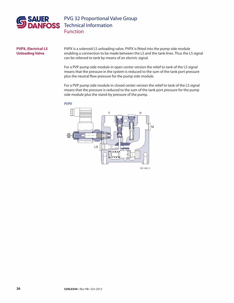
PVPX
PVPX, Electrical LS
Unloading Valve
27520L0344
PVG 32 Proportional Valve Group
Technical InformationTechnical Data
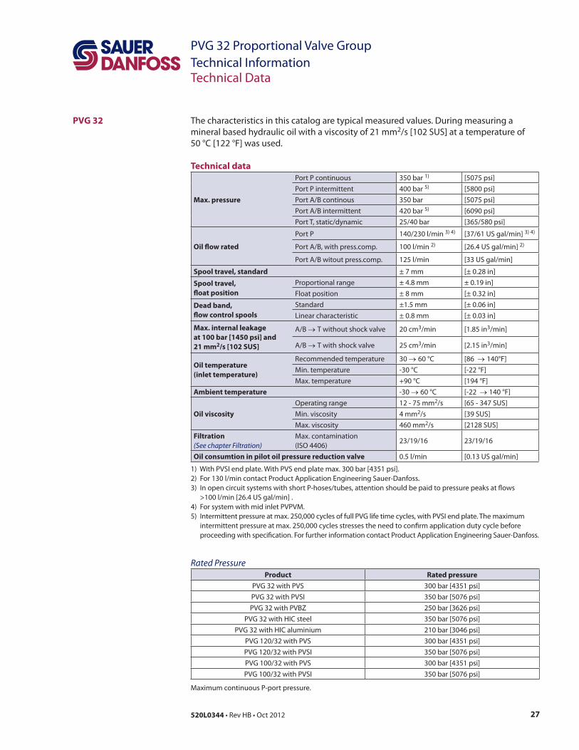
PVG 322
Technical data
Max. pressure
Port P intermittent
Oil $ow rated
Port P
Spool travel, standard
Spool travel,
$oat position ± 8 mm
Dead band,
$ow control spools
Standard
Max. internal leakage
at 100 bar [1450 psi] and
21 mm2/s [102 SUS]
3/min 3
3/min 3
Oil temperature
(inlet temperature)
Ambient temperature
Oil viscosity
2
2
2
Filtration
(See chapter Filtration)
Oil consumtion in pilot oil pressure reduction valve
Rated Pressure
Product Rated pressure
PVG 32 with PVS
PVG 32 with PVSI
28 520L0344
PVG 32 Proportional Valve Group
Technical InformationTechnical Data
PVM, Mechanical
Actuation
Technical data for PVM
Spool displacementOperating Torque
PVM + PVMD PVM + PVE 1) PVM + PVH PVM + PVMR PVM+PVMF
22
– –
– – – –
– – – –
– – – –
Control lever position No
Control range
control lever
proportional
the PVE-Series 4 for PVG 32, PVG 100 and PVG 120 Technical Information, 520L0553
Technical data for PVH
Control range pressure
Max. pilot pressure
Max. pressure on port T*
PVH, Hydraulic Actuation
29520L0344
PVG 32 Proportional Valve Group
Technical InformationTechnical Data
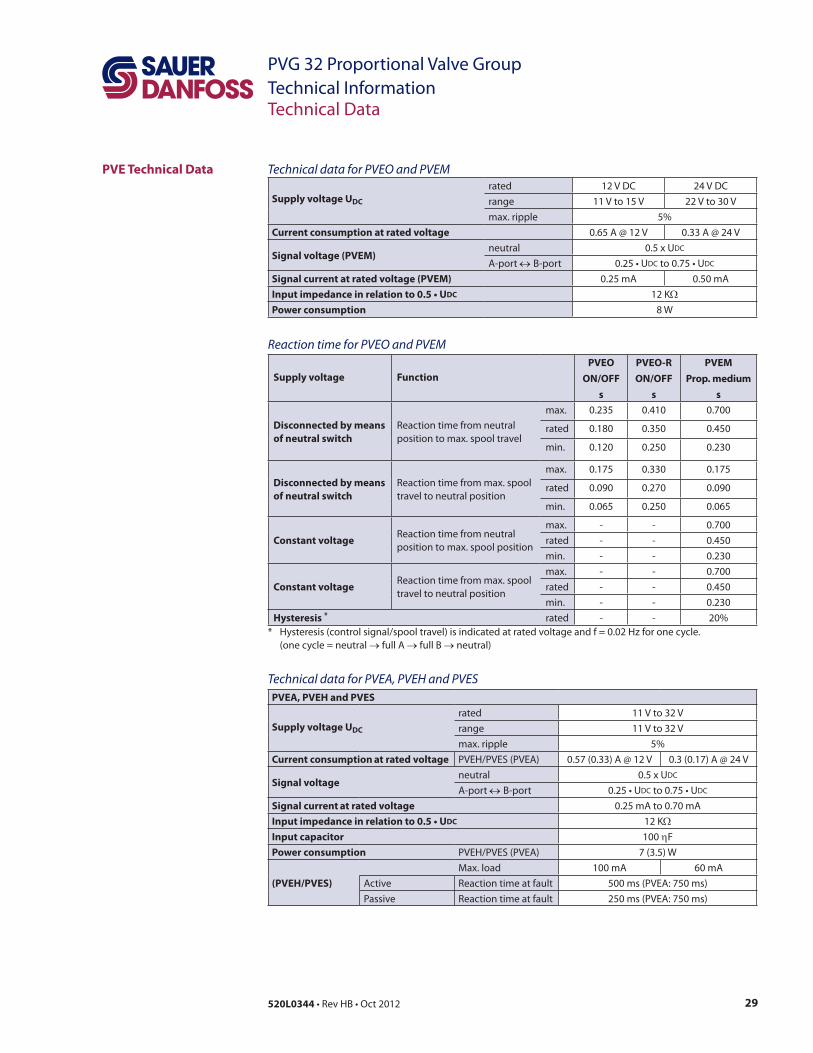
PVE Technical Data Technical data for PVEO and PVEM
Supply voltage UDC
rated
Current consumption at rated voltage
Signal voltage (PVEM)neutral DC
DC DC
Signal current at rated voltage (PVEM)
DC
Power consumption
Reaction time for PVEO and PVEM
Supply voltage Function
PVEO
ON/OFF
s
PVEO-R
ON/OFF
s
PVEM
Prop. medium
s
Disconnected by means
of neutral switchrated
Disconnected by means
of neutral switchrated
Constant voltage rated
Constant voltage rated
Hysteresis * rated
full A
Technical data for PVEA, PVEH and PVES
PVEA, PVEH and PVES
Supply voltage UDC
rated
Current consumption at rated voltage
Signal voltageneutral DC
DC DC
Signal current at rated voltage
DC
Input capacitor F
Power consumption
(PVEH/PVES) Active
30 520L0344
PVG 32 Proportional Valve Group
Technical InformationTechnical Data
PVE Technical Data
(continued)
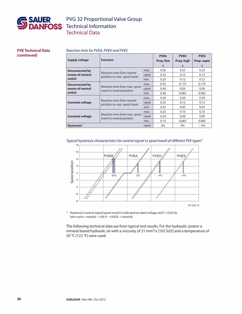
Reaction time for PVEA, PVEH and PVES
Supply voltage Function
PVEA
Prop. "ne
s
PVEH
Prop. high
s
PVES
Prop. super
s
Disconnected by
means of neutral
switch
rated
Disconnected by
means of neutral
switch
rated
Constant voltage rated
Constant voltage rated
Hysteresis * rated
Typical hysteresis characteristics for control signal vs spool travel af di#erent PVE types*
full A
2
31520L0344
PVG 32 Proportional Valve Group
Technical InformationTechnical Data
Oil viscosity *
recommended range 2
minimum 2
maximum 2
Oil temperature
recommended range
minimum
maximum
Ambient temperature recommended range
Filtering in the hydraulic system
2
PVE Technical Data
(continued)
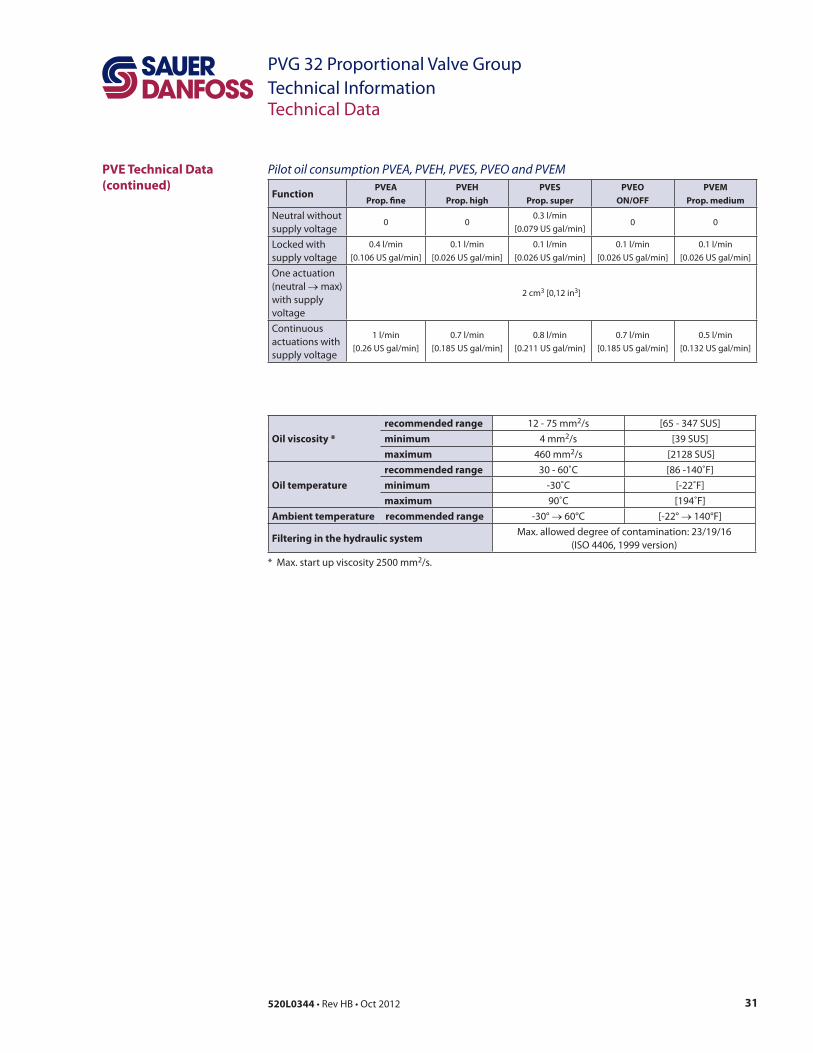
Pilot oil consumption PVEA, PVEH, PVES, PVEO and PVEM
FunctionPVEA
Prop. "ne
PVEH
Prop. high
PVES
Prop. super
PVEO
ON/OFF
PVEM
Prop. medium
Neutral without
(neutral 2 cm3 3
32 520L0344
PVG 32 Proportional Valve Group
Technical InformationTechnical Data
PVPX, Electrical LS
Unloading Valve
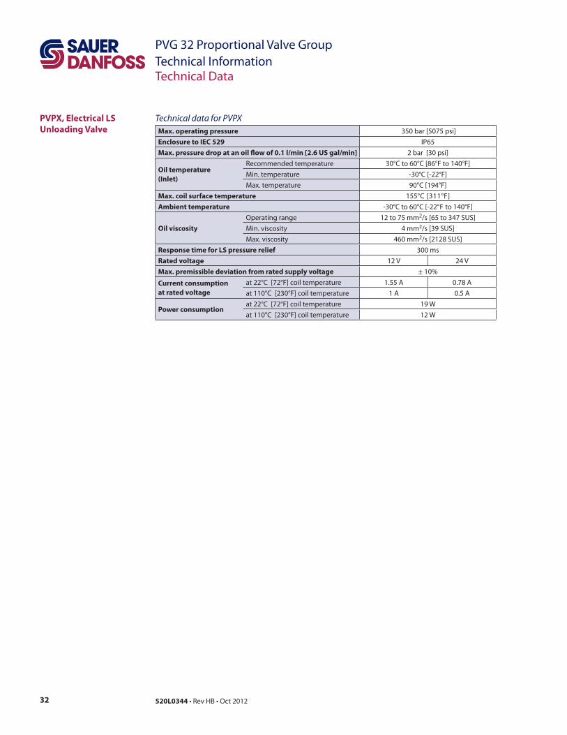
Technical data for PVPX
Max. operating pressure
Enclosure to IEC 529
Max. pressure drop at an oil $ow of 0.1 l/min [2.6 US gal/min]
Oil temperature
(Inlet)
Max. coil surface temperature
Ambient temperature
Oil viscosity
2
2
2
Response time for LS pressure relief
Rated voltage
Max. premissible deviation from rated supply voltage
Current consumption
at rated voltage
Power consumption
33520L0344
PVG 32 Proportional Valve Group
Technical InformationElectrical Actuation
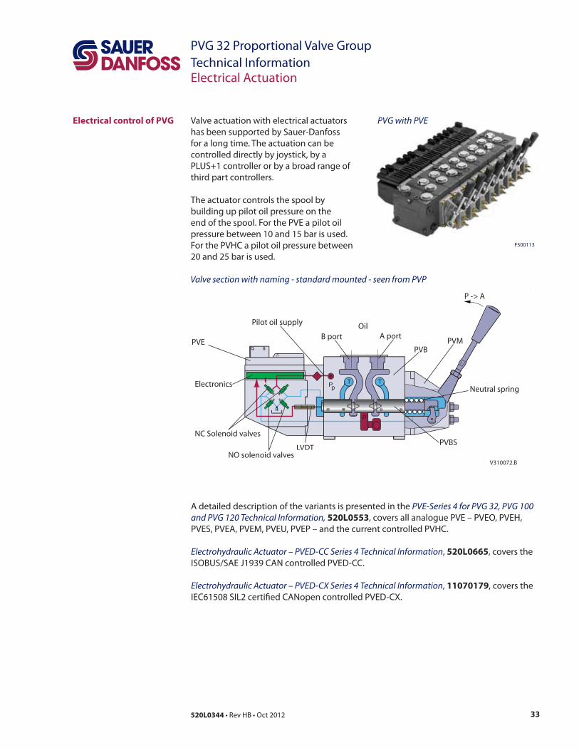
V310072.B
PVE
Electronics
NC Solenoid valves
Pilot oil supply
B port
Oil
A port
PVBPVM
Neutral spring
PVBS
NO solenoid valvesLVDT
P -> A
Electrical control of PVG PVG with PVE
Valve section with naming - standard mounted - seen from PVP
PVE-Series 4 for PVG 32, PVG 100
and PVG 120 Technical Information, 520L0553
Electrohydraulic Actuator – PVED-CC Series 4 Technical Information 520L0665
Electrohydraulic Actuator – PVED-CX Series 4 Technical Information 11070179
34 520L0344
PVG 32 Proportional Valve Group
Technical InformationElectrical Actuation
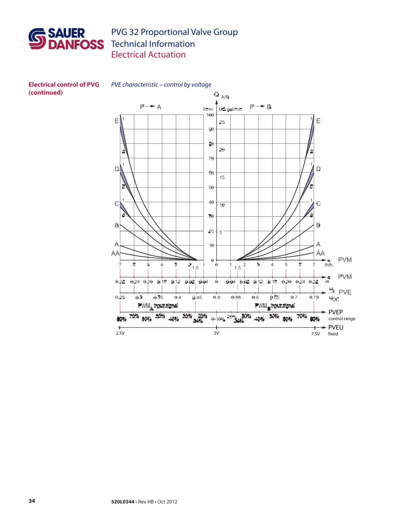
Electrical control of PVG
(continued)
PVE characteristic – control by voltage
PVEPcontrol range
PVEU�xed7.5V5V2.5V
35520L0344
PVG 32 Proportional Valve Group
Technical InformationElectrical Actuation
Closed loop control
Hysteresis for PVE variants*
full A
PVE Technical Information 520L0553
Fault monitoring overview
TypeFault
monitoring
Delay before
error outError mode
Error
output
status
Fault
output on
PVE 1)
LED light
Memory
(reset
needed)
PVEO
PVEM
No fault – – – – – –
PVEA
PVEH
PVEP
PVES
PVEU
Active
No fault < 2 V Green –
DC
No fault < 2 V Green –
DC No
PVE
Float
six pin
Active
Float not active
D
36 520L0344
PVG 32 Proportional Valve Group
Technical InformationElectrical Actuation
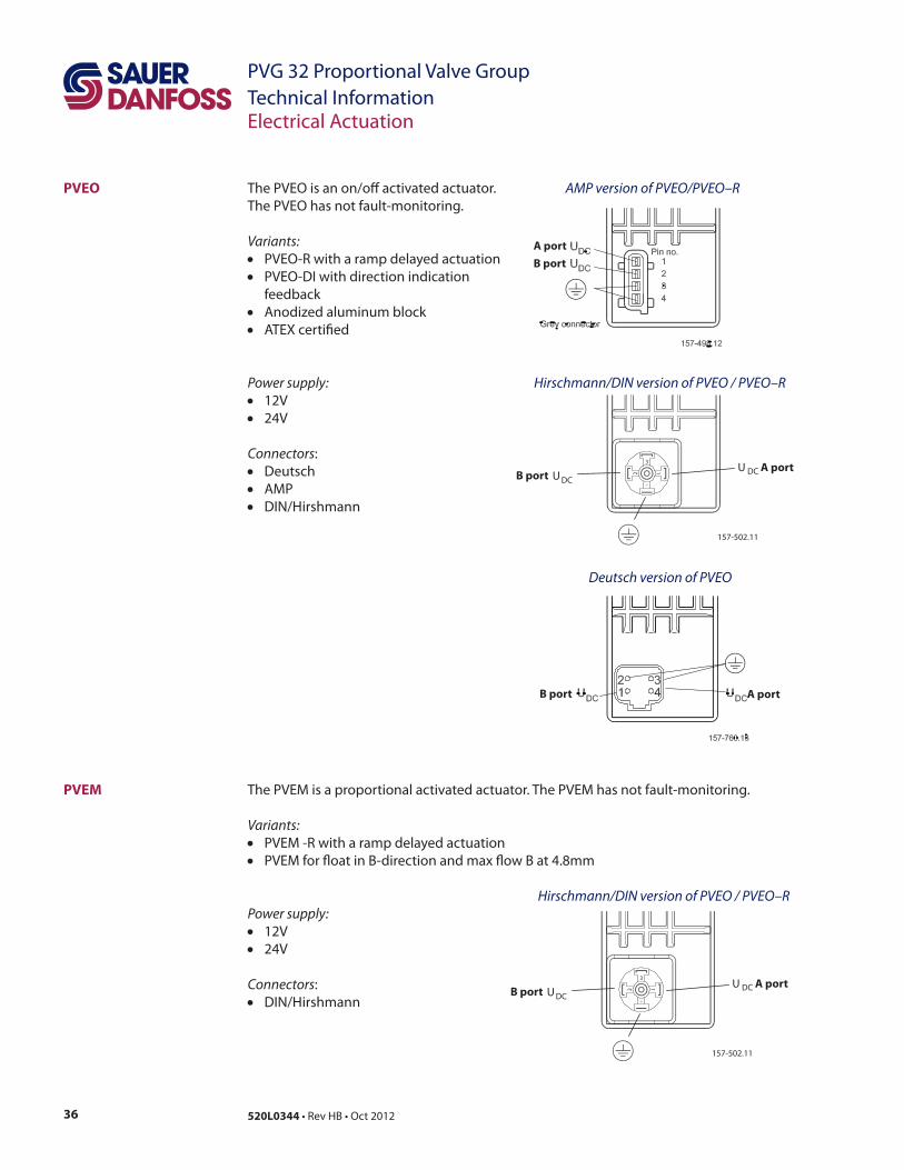
PVEM
Variants:
Power supply:
Connectors
Hirschmann/DIN version of PVEO / PVEO–R
PVEO AMP version of PVEO/PVEO–R
Hirschmann/DIN version of PVEO / PVEO–R
Deutsch version of PVEO
A port
B port
Variants:
feedback
Power supply:
Connectors
AMP
A port
157-502.11
DC
DCUU
3
1
2
A portB port
B port
157-502.11
DC
DCUU
3
1
2
A portB port
37520L0344
PVG 32 Proportional Valve Group
Technical InformationElectrical Actuation
PVEP
Power supply:
Connectors:
Not
connected
Error
Us
321
456
Spool position
UDC
LED
Deutsch version PVEP
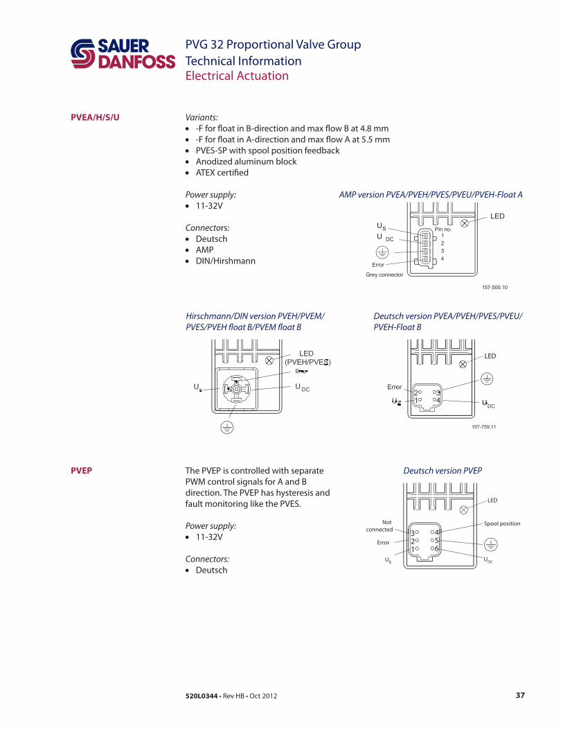
PVEA/H/S/U
LED
AMP version PVEA/PVEH/PVES/PVEU/PVEH-Float A
Deutsch version PVEA/PVEH/PVES/PVEU/
PVEH-Float B
Hirschmann/DIN version PVEH/PVEM/
PVES/PVEH $oat B/PVEM $oat B
Variants:
Power supply:
Connecto
AMP
38 520L0344
PVG 32 Proportional Valve Group
Technical InformationElectrical Actuation
Power supply:
Connecto
PVE with Deutsch connector incl. female connector
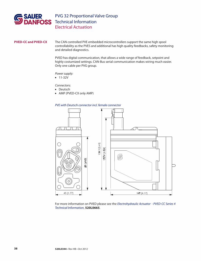
PVED-CC and PVED-CX
Electrohydraulic Actuator - PVED-CC Series 4
Technical Information 520L0665
39520L0344
PVG 32 Proportional Valve Group
Technical InformationElectrical Actuation
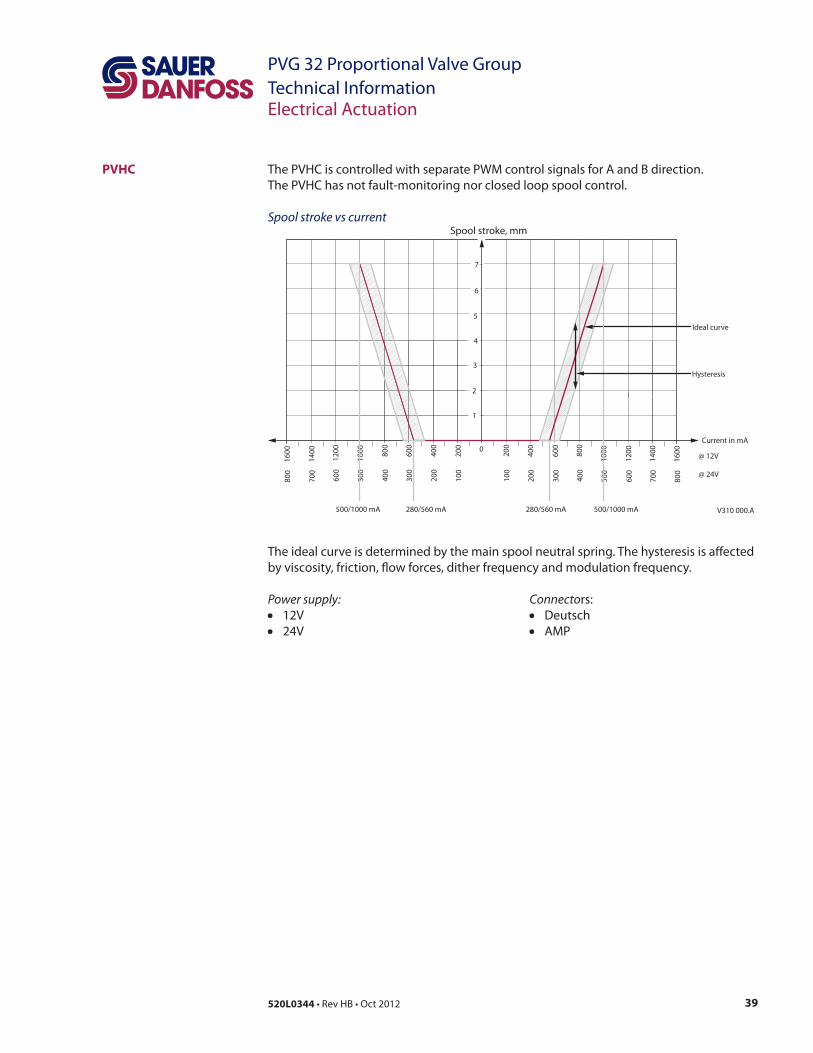
PVHC
Spool stroke vs current
0
40
0
20
0
60
0
1
2
12
00
80
0
10
00
14
00
Current in mA
3
4
5
6
Spool stroke, mm
7
16
00
40
0
20
0
60
0
12
00
80
0
10
00
14
00
16
00
20
0
10
0
30
0
60
0
40
0
50
0
70
0
80
0
20
0
10
0
30
0
60
0
40
0
50
0
70
0
80
0
@ 12V
@ 24V
V310 000.A
Ideal curve
Hysteresis
280/560 mA 500/1000 mA280/560 mA500/1000 mA
Power supply: Connecto
AMP
40 520L0344
PVG 32 Proportional Valve Group
Technical Information
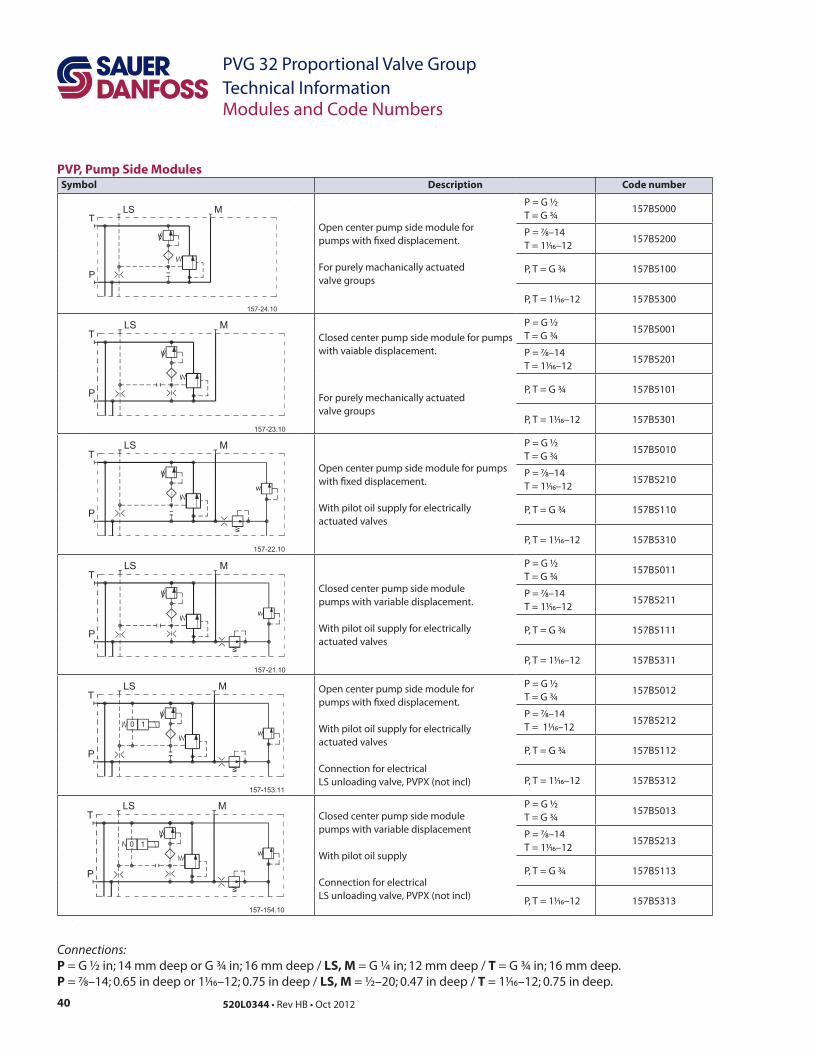
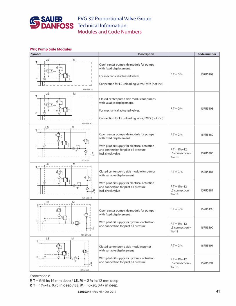
PVP, Pump Side ModulesSymbol Description Code number
7/8–14
1/16
1/16
7/8–14
1/16
1/16
7/8–14
1/16
1/16
7/8–14
1/16
1/16
Connection for electrical
7/8–14
1/16
1/16
Connection for electrical
7/8–14
1/16
1/16
Connections:
P = G ½ in; 14 mm deep or G ¾ in; 16 mm deep / LS, M = G ¼ in; 12 mm deep / T = G ¾ in; 16 mm deep.
P = 7/8–14; 0.65 in deep or 1/16 ; 0.75 in deep / LS, M = ½–20; 0.47 in deep / T = 1/16 ; 0.75 in deep.
41520L0344
PVG 32 Proportional Valve Group
Technical Information
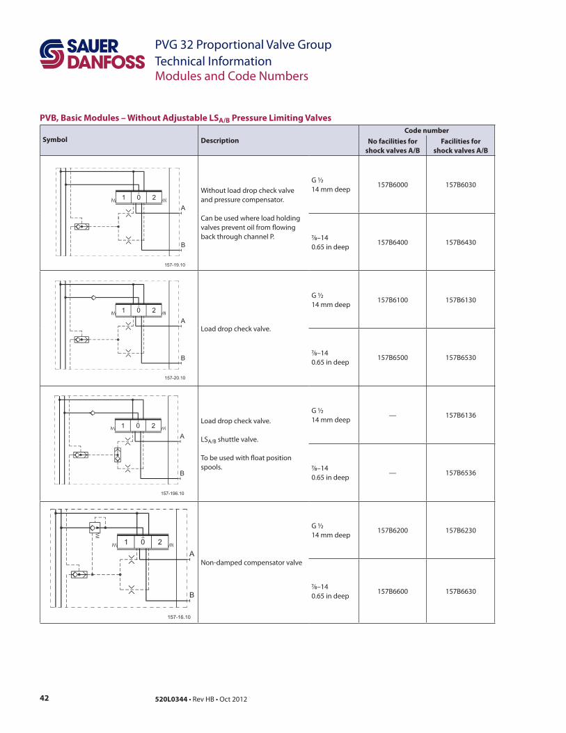
PVP, Pump Side Modules
Symbol Description Code number
1/16
9/16
1/16
9/16
1/16
9/16
1/16
9/16
Connections:
P, T = G ¾ in; 16 mm deep / LS, M = G ¼ in; 12 mm deep
P, T = 1/16 ; 0.75 in deep / LS, M = ½–20; 0.47 in deep.
42 520L0344
PVG 32 Proportional Valve Group
Technical Information
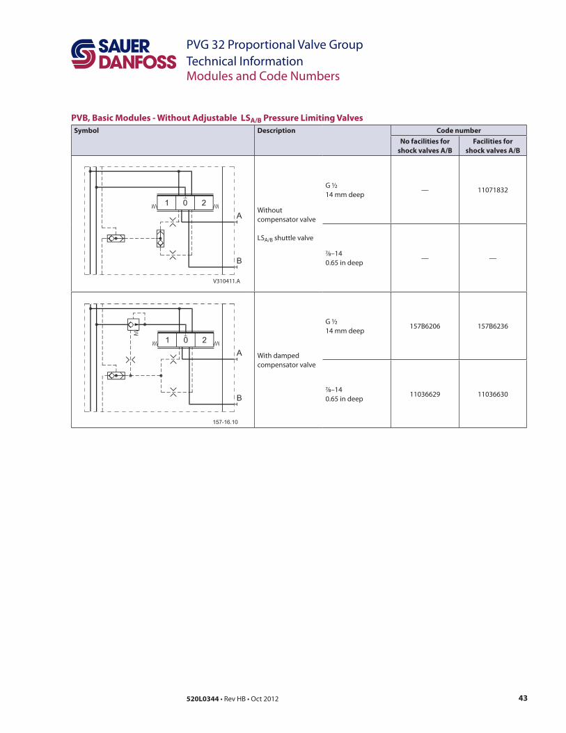
PVB, Basic Modules – Without Adjustable LSA/B Pressure Limiting Valves
Symbol Description
Code number
No facilities for
shock valves A/B
Facilities for
shock valves A/B
7/8–14
7/8–14
—
7/8–14—
7/8–14
43520L0344
PVG 32 Proportional Valve Group
Technical Information
V310411.A
PVB, Basic Modules - Without Adjustable LSA/B Pressure Limiting Valves
Symbol Description Code number
No facilities for
shock valves A/B
Facilities for
shock valves A/B
—
7/8–14— —
7/8–14
44 520L0344
PVG 32 Proportional Valve Group
Technical Information
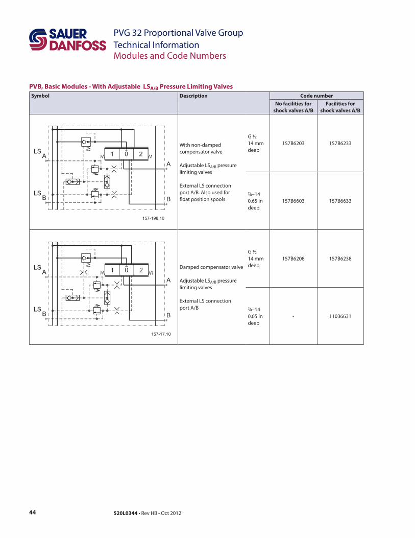
PVB, Basic Modules - With Adjustable LSA/B Pressure Limiting Valves
Symbol Description Code number
No facilities for
shock valves A/B
Facilities for
shock valves A/B
deep
7/8–14
deep
deep
7/8–14
deep
45520L0344
PVG 32 Proportional Valve Group
Technical Information
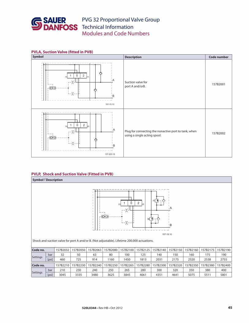
PVLA, Suction Valve ("tted in PVB)Symbol Description Code number
Suction valve for
PVLP, Shock and Suction Valve (Fitted in PVB)
Symbol / Description
Code no.
bar 32 63
Code no.
bar
46 520L0344
PVG 32 Proportional Valve Group
Technical Information
PVM, Mechanical Actuation
Symbol DescriptionCode number
with stop screws w/o stop screws
PVMD, Cover for Mechanical Actuation
Symbol Description Material Code No. Anodized
—
aluminium no
aluminium
no
PVMR, Friction Detent
Symbol Description Material Code number Anodized
aluminium no
aluminium
PVMF, Mechanical Float Position
Symbol Description Material Code number Anodized
aluminium no
PVH, Hydraulic Actuation
Symbol Description Material Code number Anodized
aluminium no
aluminium
no
aluminium no
aluminium
no
47520L0344
PVG 32 Proportional Valve Group
Technical Information
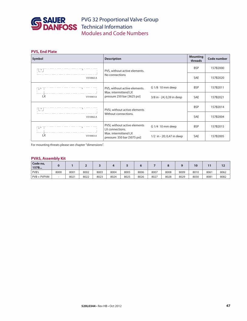
PVS, End Plate
Symbol DescriptionMounting
threadsCode number
V310062.A SAE
V310063.ALX SAE
V310062.A SAE
V310063.ALX SAE
PVAS, Assembly Kit
Code no,
157B...0 1 2 3 4 5 6 7 8 9 10 11 12
48 520L0344
PVG 32 Proportional Valve Group
Technical Information
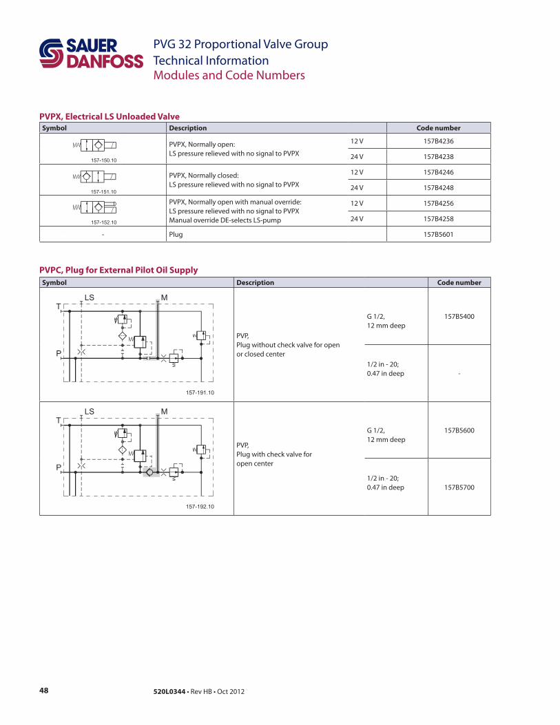
PVPX, Electrical LS Unloaded Valve
Symbol Description Code number
PVPC, Plug for External Pilot Oil Supply
Symbol Description Code number
open center
49520L0344
PVG 32 Proportional Valve Group
Technical Information
General
PVP, Pump Side Module
2
Pressure relief valve characteristic in PVP
Pressure relief valve characteristic
Neutral by-pass pressure drop charastic (open center)
50 520L0344
PVG 32 Proportional Valve Group
Technical Information
Oil $ow characteristics
The oil flow for the individual spool depends on:
Pressure-compensated PVB, open or closed center PVP
The oil flow is dependent on the supplied pump oil flow. The characteristics are plotted
for a pump oil flow, QP, corresponding to the rated max. spool oil flow, QN. Increasing the
pump oil flow to 1,4 × QN will give the same oil flow on the eighth as on the first basic
module.
Please note, the letters AA, A, B, etc. denote spool types. The characteristic below is shown
for spool travel in both directions. All other characteristics are shown for spool travel
in one direction only.
Progressive oil $ow characteristic depending on spool type
157-61.im
PWM for PVEP/T
control range
PVE
PVM
PVM
PVB
S
DC
51520L0344
PVG 32 Proportional Valve Group
Technical Information
Linear oil $ow depending on spool type
S
DC
PVB, Basic Modules
52 520L0344
PVG 32 Proportional Valve Group
Technical Information
PVB without pressure compensation, open center PVP
Oil $ow as a function of spool travel
P
Oil $ow as a function of spool travel characteristic
PVB, Basic Modules
(continued)
53520L0344
PVG 32 Proportional Valve Group
Technical Information
PVB, Basic Module
(continued)
Characteristic for fully displaced $ow control spools
Oil $ow QA/B as a function of supplied pump oil $ow (QP)
P
54 520L0344
PVG 32 Proportional Valve Group
Technical Information
PVB, Basic Module
(continued)
PVB without pressure compensation, closed center PVP
55520L0344
PVG 32 Proportional Valve Group
Technical Information
Characteristic for pressure drop PVB at max. main spool travel PVB, Basic Module
(continued)
Characteristic for pressure drop PVB for open spool in neutral position
56 520L0344
PVG 32 Proportional Valve Group
Technical Information
Load-independent oil $ow characteristic, pressure-compensated PVB
Oil $ow characteristic at LS pressure limiting, pressure-compensated PVB
PVB, Basic Module
(continued)
57520L0344
PVG 32 Proportional Valve Group
Technical Information
PVLP, Shock and Suction
Valve
PVLA, Suction Valve
PVLP, shock valve
PVLP, shock valve characteristic
PVLA, suction valve characteristic
58 520L0344
PVG 32 Proportional Valve Group
Technical Information
Pressure Control Spool Flow Characteristics in Various Positions
Size A:
Size C:
Example 1
Size D:
Example 2
Size E:
Size B:
59520L0344
PVG 32 Proportional Valve Group
Technical Information
Examples of How To Use
the Characteristics for
Pressure Control Spools
Example 1: Determining the oil $ow
–
–
–
–
Example 2: Determining the spool size
–
– P
–A
– previous page, size D
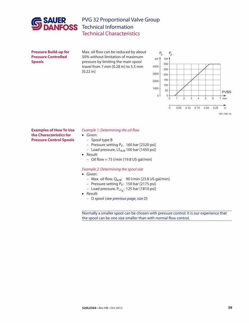
Pressure Build-up for
Pressure Controlled
Spools
60 520L0344
PVG 32 Proportional Valve Group
Technical Information
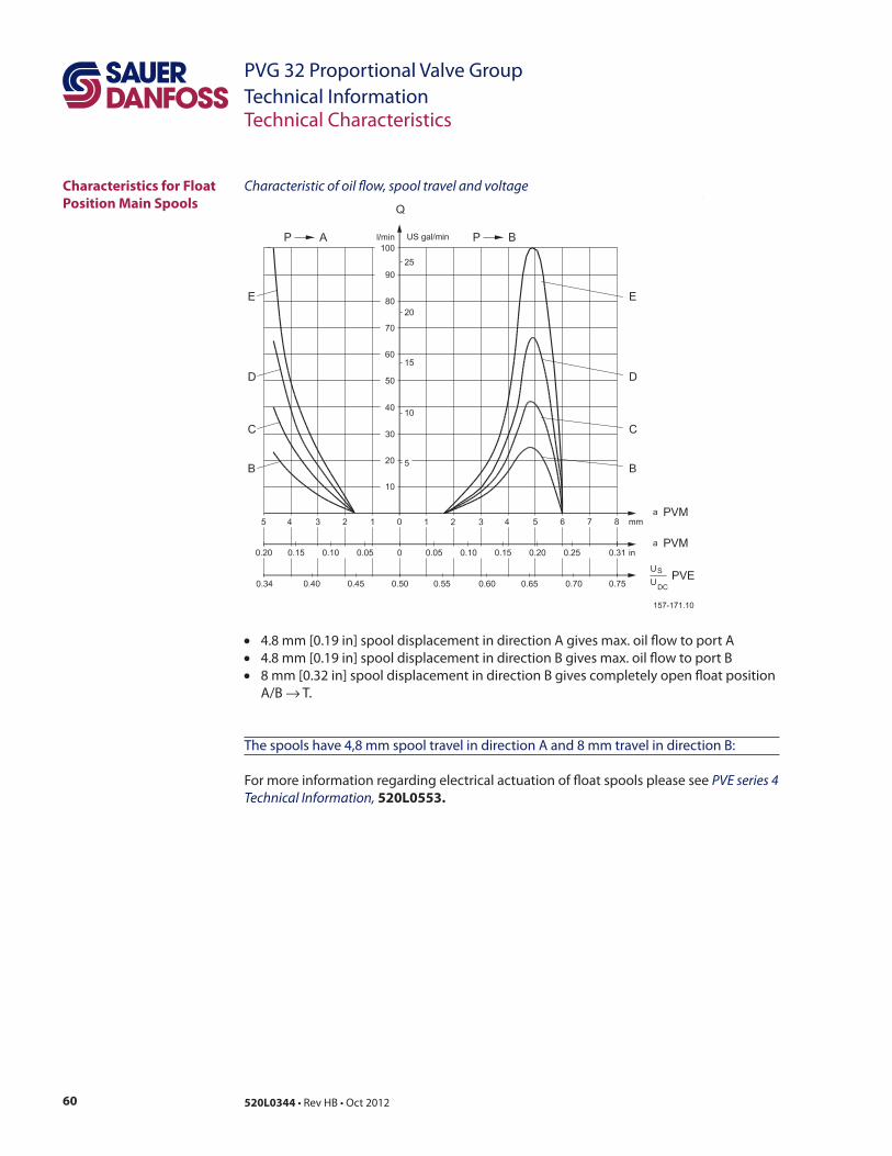
Characteristic of oil $ow, spool travel and voltageCharacteristics for Float
Position Main Spools
→
PVE series 4
Technical Information, 520L0553.
61520L0344
PVG 32 Proportional Valve Group
Technical Information
Characteristics for Float
Position Main Spools
(continued)
Pressure drop A/B → T in $oat position
Pressure drop A/B → T at max. spool travel within the proportional range (4.8 mm) [0.19 in]
62 520L0344
PVG 32 Proportional Valve Group
Technical Information
Dimensions
9/
9/
deep
× /
/8
PVB 1 2 3 4 5 6 7 8 9 10 11 12
L1mm 82 226 322
L2mm 238 336 622
V310344
F
J K
G H
O
N
I QP
L
R
S
/83/8
/
/8
/
A9/
PVG 32 Dimensions
63520L0344
PVG 32 Proportional Valve Group
Technical Information
Dimensions (continued)
/ /2
F
max.290.50[11.437]
107[4.21]
max.290.50[11.437]
12
9[5
.08
]
95
[3.7
4]
7[0
.28
]
M
85
[3.3
5]
17[0.67]
A-A
110[4.33] 60[2.36]
PV
D85
[3.3
5]
58
.5[2
.30
3] 3
2[1
.26
]6
.5[0
.25
6]
33[1.30]
7[0
.28
]
max.200.5[7.894]
13
[0.5
1]
110[4.33]
B-B
60[2.36]
110[4.33]
C-C
60[2.36]
7[0
.28
]
45
[1.7
7]
7[0
.28
]
49.5[1.949]
PVMR/F
107[4.21]
11
7[4
.61
]
13
9[5
.47
2]
~ 1
65
[6.5
0]
44
[1
.73
2]
89.5[3.524]
85.5[3.366]
PVEO
PVEM/PVEH/
PVH
V310141.A
PVES
64 520L0344
PVG 32 Proportional Valve Group
Technical Information
Control Lever Positions Mounted with an angle of 22.5°
22.5˚ 52.5˚ 82.5˚ 112.5˚
142.5˚ 172.5˚
19.5˚
19.5˚
V310014.A
37.5˚67.5˚
97.5˚
127.5˚
157.5˚
187.5˚
19.5˚
19.5˚
V310018.A
Mounted with an angle of 37.5°
Surface Treatment
65520L0344
PVG 32 Proportional Valve Group
Technical Information
Manually Actuated PVG 32 – Fixed Displacement Pump
Example of manually actuated PVG 32 – "xed displacement pump schematic
66 520L0344
PVG 32 Proportional Valve Group
Technical Information
Electrically Actuated PVG 32 – Variable Displacement Pump
Example of electrically actuated PVG 32 – variable displacement pump (electrical actuator, shock valves, relief valve) schematic
67520L0344
PVG 32 Proportional Valve Group
Technical Information
Oil
Mineral oil
Non-$ammable $uids
Particle Content, Degree
of Contamination
Biodegradable oils
Design Guidelines for Hydraulic Fluid Cleanliness Technical Information, 520L0467
Hydraulic Fluids and Lubricants Technical Information, 521L0463
Experience with Bio-Hydraulic Fluids Technical Information, 521L0465.
68 520L0344
PVG 32 Proportional Valve Group
Technical Information
Filtration
System "lters
Internal "lters
69520L0344
PVG 32 Proportional Valve Group
Technical InformationModule Selection Chart
Standard FC Spools
To be used when PVB
is with LSA/B shuttle valveCode number
157B....
To be used when PVB
is without LSA/B shuttle valve
Size Size
Press. compensated $ow
l/min [US gal/min]
ISO symbol Symbol
Press. compensated $ow
l/min [US gal/min]
F
130
[34.3]
E
100
[26.4]
D
65
[17.2]
C
40
[10.6]
B
25
[6.6]
A
10
[2.6]
AA
5
[1.3]
AA
5
[1.3]
A
10
[2.6]
B
25
[6.6]
C
40
[10.6]
D
65
[17.2]
E
100
[26.4]
F
130
[34.3]
→ A
→
70 520L0344
PVG 32 Proportional Valve Group
Technical Information
Standard FC Spools
To be used when PVB
is with LSA/B shuttle valveCode number
157B....
To be used when PVB
is without LSA/B shuttle valve
Size Size
Press. compensated $ow
l/min [US gal/min]
ISO symbol Symbol
Press. compensated $ow
l/min [US gal/min]
F
130
[34.3]
E
100
[26.4]
D
65
[17.2]
C
40
[10.6]
B
25
[6.6]
A
10
[2.6]
AA
5
[1.3]
AA
5
[1.3]
A
10
[2.6]
B
25
[6.6]
C
40
[10.6]
D
65
[17.2]
E
100
[26.4]
F
130
[34.3]
→
→
Float P → → F
Module Selection Chart
157-139.10
157-140.10
71520L0344
PVG 32 Proportional Valve Group
Technical Information
FC Spools for Mechanical Float Position PVMF
To be used when PVB
is with LSA/B shuttle valveCode number
157B....
To be used when PVB
is without LSA/B shuttle valve
Size Size
Press. compensated $ow
l/min [US gal/min]
ISO symbol Symbol
Press. compensated $ow
l/min [US gal/min]
F
130
[34.3]
E
100
[26.4]
D
65
[17.2]
C
40
[10.6]
B
25
[6.6]
A
10
[2.6]
AA
5
[1.3]
AA
5
[1.3]
A
10
[2.6]
B
25
[6.6]
C
40
[10.6]
D
65
[17.2]
E
100
[26.4]
F
130
[34.3]
9823 9822
P → A → F
623 9622
Float P → → F
Module Selection Chart
157-139.10
157-140.10
72 520L0344
PVG 32 Proportional Valve Group
Technical InformationModule Selection Chart
Standard FC Spools, Hydraulic Actuation
To be used when PVB
is with LSA/B shuttle valveCode number
157B....
To be used when PVB
is without LSA/B shuttle valve
Size Size
Press. compensated $ow
l/min [US gal/min]
ISO symbol Symbol
Press. compensated $ow
l/min [US gal/min]
E
100
[26.4]
D
65
[17.2]
C
40
[10.6]
B
25
[6.6]
A
10
[2.6]
AA
5
[1.3]
AA
[1.3]
A
10
[2.6]
B
25
[6.6]
C
40
[10.6]
D
65
[17.2]
E
100
[26.4]
PVMR, FC Spools for Friction Detent
To be used when PVB
is with LSA/B shuttle valveCode number
157B....
To be used when PVB
is without LSA/B shuttle valve
Size Size
Press. compensated $ow
l/min [US gal/min]
ISO symbol Symbol
Press. compensated $ow
l/min [US gal/min]
E
100
[26.4]
D
65
[17.2]
C
40
[10.6]
B
25
[6.6]
A
10
[2.6]
AA
5
[1.3]
AA
[1.3]
A
10
[2.6]
B
25
[6.6]
C
40
[10.6]
D
65
[17.2]
E
100
[26.4]

73520L0344
PVG 32 Proportional Valve Group
Technical Information
FC Spools with Linear Flow Characteristic
To be used when PVB
is with LSA/B shuttle valveCode number
157B....
To be used when PVB
is without LSA/B shuttle valve
Size Size
Press. compensated $ow
l/min [US gal/min]
ISO symbol Symbol
Press. compensated $ow
l/min [US gal/min]
F
130
[34.3]
E
100
[26.4]
D
65
[17.2]
C
40
[10.6]
B
25
[6.6]
A
10
[2.6]
AA
5
[1.3]
AA
5
[1.3]
A
10
[2.6]
B
25
[6.6]
C
40
[10.6]
D
65
[17.2]
E
100
[26.4]
F
130
[34.3]
→
→
Module Selection Chart
74 520L0344
PVG 32 Proportional Valve Group
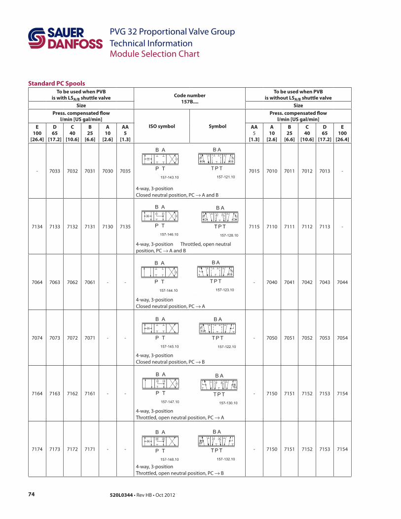
Technical InformationModule Selection Chart
Standard PC Spools
To be used when PVB
is with LSA/B shuttle valve Code number
157B....
To be used when PVB
is without LSA/B shuttle valve
Size Size
Press. compensated $ow
l/min [US gal/min]
ISO symbol Symbol
Press. compensated $ow
l/min [US gal/min]
E
100
[26.4]
D
65
[17.2]
C
40
[10.6]
B
25
[6.6]
A
10
[2.6]
AA
5
[1.3]
AA
[1.3]
A
10
[2.6]
B
25
[6.6]
C
40
[10.6]
D
65
[17.2]
E
100
[26.4]
→
→
→ A
→
→ A
→
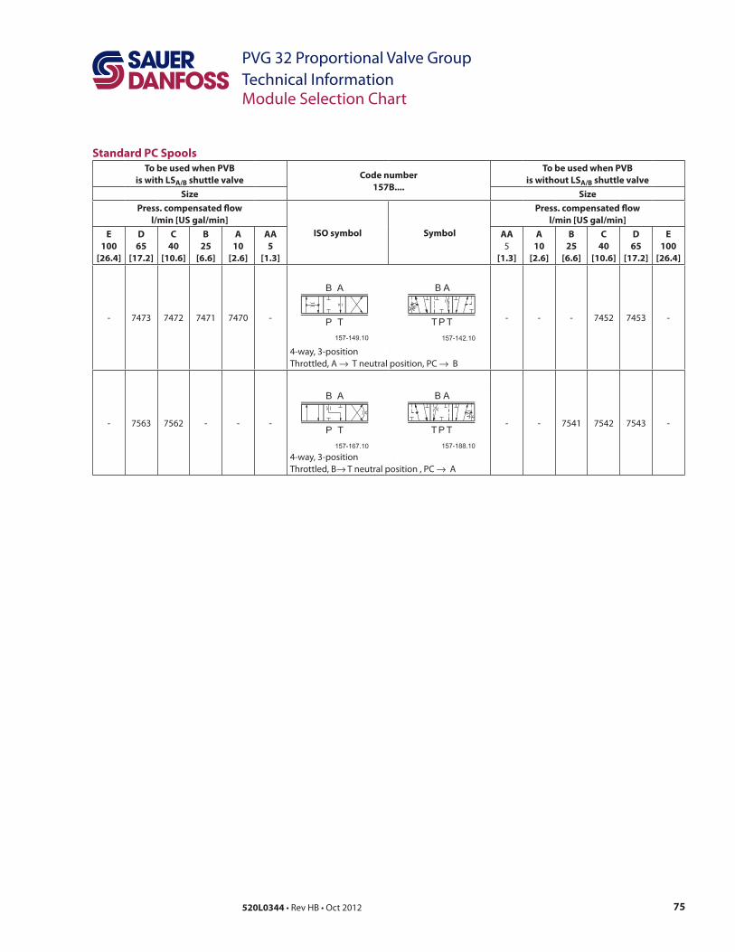
75520L0344
PVG 32 Proportional Valve Group
Technical InformationModule Selection Chart
Standard PC Spools
To be used when PVB
is with LSA/B shuttle valveCode number
157B....
To be used when PVB
is without LSA/B shuttle valve
Size Size
Press. compensated $ow
l/min [US gal/min]
ISO symbol Symbol
Press. compensated $ow
l/min [US gal/min]
E
100
[26.4]
D
65
[17.2]
C
40
[10.6]
B
25
[6.6]
A
10
[2.6]
AA
5
[1.3]
AA
[1.3]
A
10
[2.6]
B
25
[6.6]
C
40
[10.6]
D
65
[17.2]
E
100
[26.4]
→ →
→ → A
76 520L0344
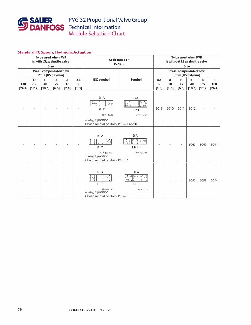
PVG 32 Proportional Valve Group
Technical InformationModule Selection Chart
Standard PC Spools, Hydraulic Actuation
To be used when PVB
is with LSA/B shuttle valveCode number
157B....
To be used when PVB
is without LSA/B shuttle valve
Size Size
Press. compensated $ow
l/min [US gal/min]
ISO symbol Symbol
Press. compensated $ow
l/min [US gal/min]
E
100
[26.4]
D
65
[17.2]
C
40
[10.6]
B
25
[6.6]
A
10
[2.6]
AA
5
[1.3]
AA
[1.3]
A
10
[2.6]
B
25
[6.6]
C
40
[10.6]
D
65
[17.2]
E
100
[26.4]
→
→ A
→
77520L0344
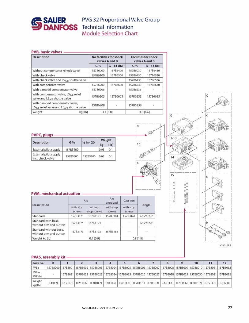
PVG 32 Proportional Valve Group
Technical InformationModule Selection Chart
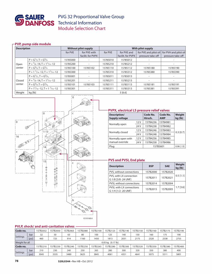
V310168.A
0
16
a
0
14
15
0
c
c
b
1-13
PVAS, assembly kit
Code no. 0 1 2 3 4 5 6 7 8 9 10 11 12
PVPVM
PVB, basic valves
Description No facilities for shock
valves A and B
Facilities for shock
valves A and B
G ½ 7∕8 - 14 UNF G ½ 7∕8 - 14 UNF
relief 6233 6633
6238
PVPC, plugs
Description G ½ ½ in - 20Weight
kg [lb]
—
PVM, mechanical actuation
Description
AluAlu
without
Standard
without arm and button— —
without arm and button— —
78 520L0344
PVG 32 Proportional Valve Group
Technical Information
PVS and PVSI, End plate
Description BSP SAEWeight
kg [lb]
PVLP, shock/ and anti-cavitation valves
Code no.
bar 32 63
Code no.
bar
Module Selection Chart
V310168.A
0
16
a
0
14
15
0
c
c
b
1-13
PVP, pump side module
Description Without pilot supply With pilot supply
for PVE for PVE with for PVE for PVE and for PVE and pilot oil
center
/ 3/
/8 /3/ 3/
/ /
center
/2 3/
/8 /3/ 3/
/ /
PVPX, electrical LS pressure relief valves
Description/
Supply voltage
Code No.
Hirsch.
Code No.
AMP
Weight
kg [lb]
manual override
79520L0344
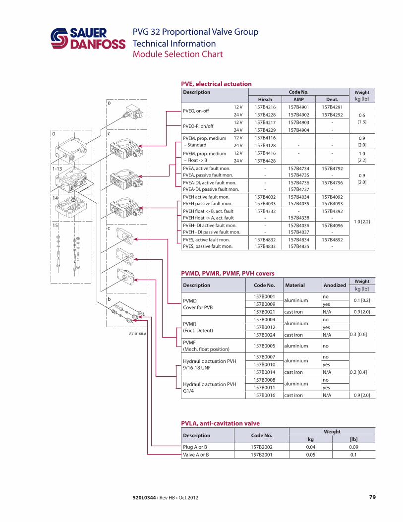
PVG 32 Proportional Valve Group
Technical InformationModule Selection Chart
V310168.A
0
14
15
0
c
c
b
1-13
PVLA, anti-cavitation valve
Description Code No.Weight
kg [lb]
PVMD, PVMR, PVMF, PVH covers
Description Code No. Material AnodizedWeight
PVMD aluminiumno
N/A
aluminiumno
N/A
PVMF aluminium no
aluminiumno
N/A
aluminiumno
N/A
PVE, electrical actuation
Description Code No. Weight
Hirsch AMP Deut.
– Standard
80 520L0344
PVG 32 Proportional Valve Group
Technical Information
Order Speci"cation
–
–
–
– Cover for mechanical actuation PVMD
–
–
–
–
Please state
–
–
–
Standard and option assembly
Reordering
81520L0344
PVG 32 Proportional Valve Group
Technical Information
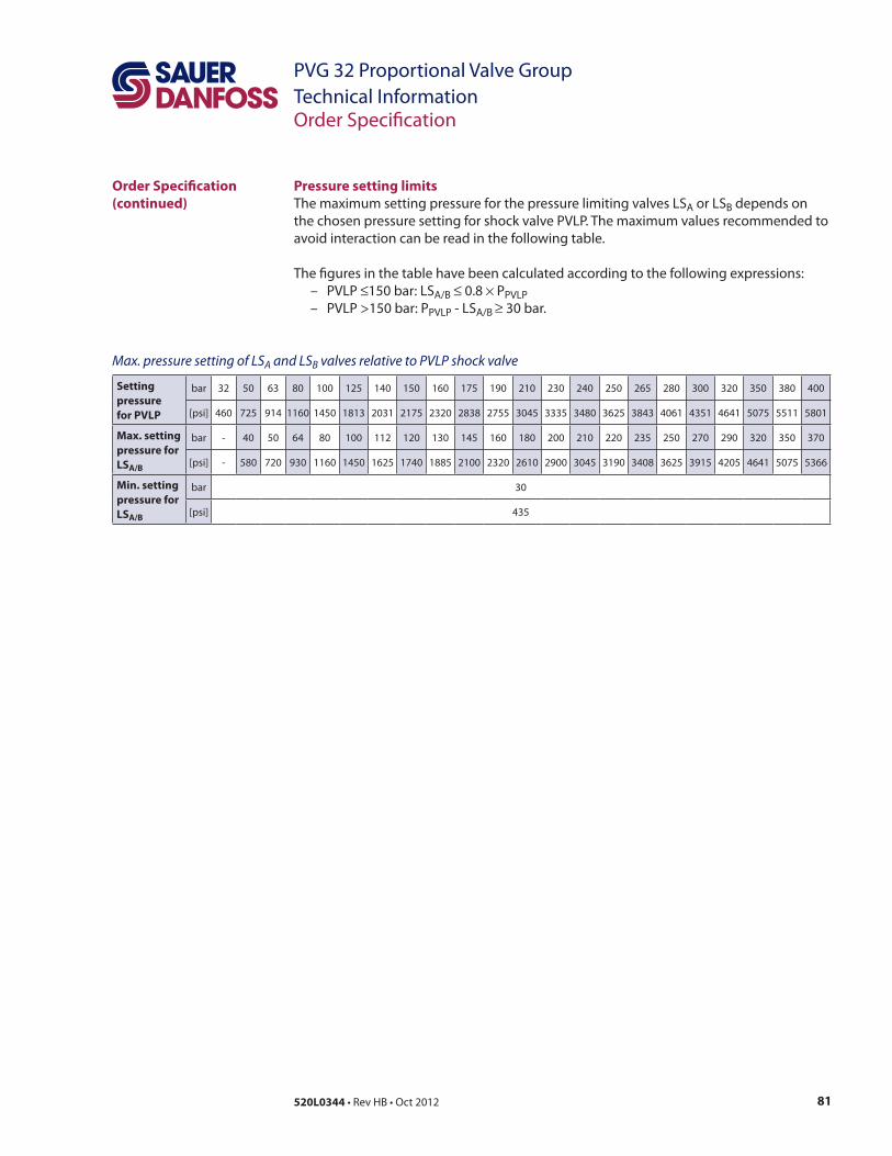
Pressure setting limits
A
– ≤ ≤ × P
– ≥
Setting
pressure
for PVLP
bar 32 63
2838
Max. setting
pressure for
LSA/B
bar
Min. setting
pressure for
LSA/B
bar
Max. pressure setting of LSA and LSB valves relative to PVLP shock valve
Order Speci"cation
(continued)
82 520L0344
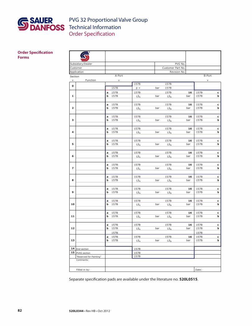
PVG 32 Proportional Valve Group
Technical Information
520L0515
Order Speci"cation
Forms
Section
v Function Extra Features
157B 157B
157B p = bar 157B
157B 157B 157B 157B
157B LSA bar LSB bar 157B
157B 157B 157B 157B
157B LSA bar LSB bar 157B
157B 157B 157B 157B
157B LSA bar LSB bar 157B
157B 157B 157B 157B
157B LSA bar LSB bar 157B
157B 157B 157B 157B
157B LSA bar LSB bar 157B
157B 157B 157B 157B
157B LSA bar LSB bar 157B
157B 157B 157B 157B
157B LSA bar LSB bar 157B
157B 157B 157B 157B
157B LSA bar LSB bar 157B
157B 157B 157B 157B
157B LSA bar LSB bar 157B
157B 157B 157B 157B
157B LSA bar LSB bar 157B
157B 157B 157B 157B
157B LSA bar LSB bar 157B
157B 157B 157B 157B
157B LSA bar LSB bar 157B
157B 157B
157B 157B 157B 157B
157B LSA bar LSB bar 157B
End section 157B
PVAS section 157B
"Reserved for Painting" 157B
Comments:
Filled in by: Date:
Application
v v
Customer
Revision No.
A-Port B-Port
Customer Part No.
PVG No.Subsidiary/Dealer
83520L0344
PVG 32 Proportional Valve Group
Technical Information
Local address:
Sauer-Danfoss GmbH & Co. OHG
Postfach 2460, D-24531 Neumünster
Krokamp 35, D-24539 Neumünster, Germany
Phone: +49 4321 871 0
Fax: +49 4321 871 122
Sauer-Danfoss ApS
DK-6430 Nordborg, Denmark
Phone: +45 7488 4444
Fax: +45 7488 4400
Sauer-Danfoss is a global manufacturer and supplier of high-
quality hydraulic and electronic components. We specialize in
providing state-of-the-art technology and solutions that excel in
the harsh operating conditions of the mobile o# -highway market.
Building on our extensive applications expertise, we work closely
with our customers to ensure exceptional performance for a broad
range of o# -highway vehicles.
We help OEMs around the world speed up system development,
reduce costs and bring vehicles to market faster.
Sauer-Danfoss – Your Strongest Partner in Mobile Hydraulics.
Go to www.sauer-danfoss.com for further product information.
Wherever o# -highway vehicles are at work, so is Sauer-Danfoss.
We o# er expert worldwide support for our customers, ensuring
the best possible solutions for outstanding performance. And with
an extensive network of Global Service Partners, we also provide
comprehensive global service for all of our components.
Please contact the Sauer-Danfoss representative nearest you.
Products we o" er:
Bent Axis Motors
Closed Circuit Axial Piston Pumps
and Motors
Displays
Electrohydraulic Power Steering
Electrohydraulics
Hydraulic Power Steering
Integrated Systems
Joysticks and Control Handles
Microcontrollers and Software
Open Circuit Axial Piston Pumps
Orbital Motors
PLUS+1™ GUIDE
Proportional Valves
Sensors
Steering
Transit Mixer Drives
Members of the Sauer-Danfoss Group:
Comatrol
www.comatrol.com
Schwarzmüller-Inverter
www.schwarzmueller-inverter.com
Turolla
www.turollaocg.com
Valmova
www.valmova.com
Hydro-Gear
www.hydro-gear.com
Sauer-Danfoss-Daikin
www.sauer-danfoss-daikin.com
Sauer-Danfoss (US) Company
2800 East 13th Street
Ames, IA 50010, USA
Phone: +1 515 239 6000
Fax: +1 515 239 6618
Sauer-Danfoss-Daikin LTD.
Shin-Osaka TERASAKI 3rd Bldg. 6F
1-5-28 Nishimiyahara, Yodogawa-ku
Osaka 532-0004, Japan
Phone: +81 6 6395 6066
Fax: +81 6 6395 8585
w w w . s a u e r - d a n f o s s . c o m520L0344