Embed Size (px)
Citation preview
PVG 100 Proportional Valve
Technical Information
2 520L0720 • Rev DA • Sep 2011
PVG 100 Proportional ValveTechnical InformationRevision History
© 2011 Sauer-Danfoss. All rights reserved.
Sauer-Danfoss accepts no responsibility for possible errors in catalogs, brochures and other printed material. Sauer -Danfoss reserves the right to alter its products without prior notice. This also applies to products already ordered provided that such alterations can be made without affecting agreed specifications. All trademarks in this material are properties of their respective owners. Sauer-Danfoss, the Sauer-Danfoss logotype, the Sauer-Danfoss S-icon, PLUS+1™, What really matters is inside® and Know-How in Motion™ are trademarks of the Sauer-Danfoss Group.
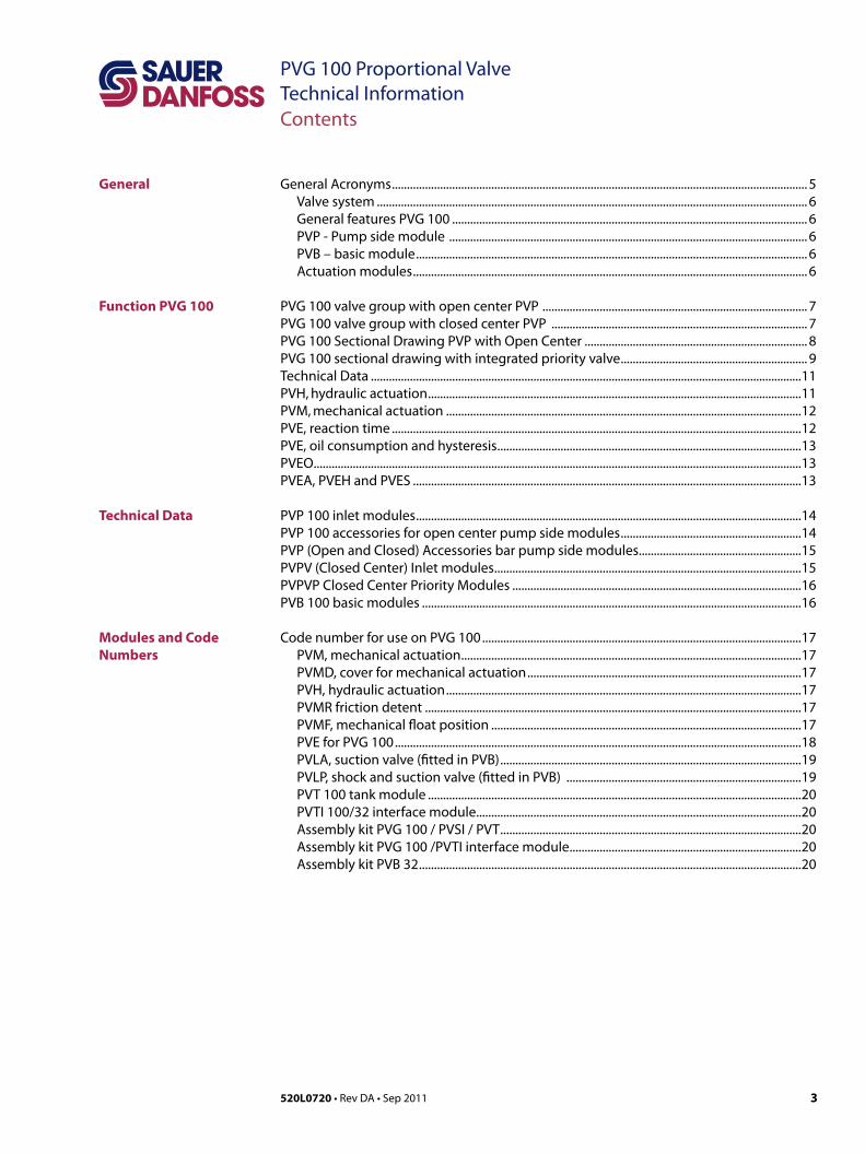
Front cover illustrations: PA270004, F301102, F301196, F301197Drawing: 157-691
Revision History Date Page Changed RevFeb 2007 All Major edition BA
Oct 2009 All Major edition CA
Nov 2009 36-37 Tabel lines moved CB
Nov 2009 16 Line added in table CC
Jan 2010 14, 17, 41 Parts numbers changed CD
Dec 2010 44 New back cover CF
Sep 2011 39-42 New 4 pages: Safety in application section DA
3520L0720 • Rev DA • Sep 2011
PVG 100 Proportional ValveTechnical InformationContents
General Acronyms .......................................................................................................................................... 5Valve system ............................................................................................................................................... 6General features PVG 100 ...................................................................................................................... 6PVP - Pump side module ....................................................................................................................... 6PVB – basic module .................................................................................................................................. 6Actuation modules ................................................................................................................................... 6
PVG 100 valve group with open center PVP ........................................................................................ 7PVG 100 valve group with closed center PVP ..................................................................................... 7PVG 100 Sectional Drawing PVP with Open Center .......................................................................... 8PVG 100 sectional drawing with integrated priority valve .............................................................. 9Technical Data ...............................................................................................................................................11PVH, hydraulic actuation ............................................................................................................................11PVM, mechanical actuation ......................................................................................................................12PVE, reaction time ........................................................................................................................................12PVE, oil consumption and hysteresis .....................................................................................................13PVEO ..................................................................................................................................................................13PVEA, PVEH and PVES .................................................................................................................................13
PVP 100 inlet modules ................................................................................................................................14PVP 100 accessories for open center pump side modules ............................................................14PVP (Open and Closed) Accessories bar pump side modules ......................................................15PVPV (Closed Center) Inlet modules ......................................................................................................15PVPVP Closed Center Priority Modules ................................................................................................16PVB 100 basic modules ..............................................................................................................................16
Code number for use on PVG 100 ..........................................................................................................17PVM, mechanical actuation .................................................................................................................17PVMD, cover for mechanical actuation ...........................................................................................17PVH, hydraulic actuation ......................................................................................................................17PVMR friction detent .............................................................................................................................17PVMF, mechanical float position .......................................................................................................17PVE for PVG 100 .......................................................................................................................................18PVLA, suction valve (fitted in PVB) ....................................................................................................19PVLP, shock and suction valve (fitted in PVB) ..............................................................................19PVT 100 tank module ............................................................................................................................20PVTI 100/32 interface module............................................................................................................20Assembly kit PVG 100 / PVSI / PVT ....................................................................................................20Assembly kit PVG 100 /PVTI interface module .............................................................................20Assembly kit PVB 32 ...............................................................................................................................20
General
Function PVG 100
Technical Data
Modules and Code Numbers
4 520L0720 • Rev DA • Sep 2011
PVG 100 Proportional ValveTechnical Information
Technical Characteristics
Dimensions
Hydraulic Systems
Other Operating Conditions
Modules and Code Numbers
Safety in Application
Module selection chart
Order specification
General .............................................................................................................................................................21PVP, pump side module .............................................................................................................................21Open center flow rating .............................................................................................................................21Flow - US - Ls Margin of full Spool Shift ................................................................................................22PVB, Basic module ........................................................................................................................................23PVLP, shock and suction valve .................................................................................................................24PVLA, suction valve ......................................................................................................................................24
Valve dimension, PVG 100, open center PVP ....................................................................................25Valve dimension, PVG100 / 32, closed center ....................................................................................26Valve dimension, PVG 100, closed center PVP with integrated priority valve........................27General dimensions .....................................................................................................................................28Valve dimension, PVG 100 with open end spool option ................................................................29
Hydraulic systems ........................................................................................................................................30Sample specification (open end spool and standard section).....................................................31
Oil .......................................................................................................................................................................32Mineral oil ..................................................................................................................................................32Non-flammable fluids............................................................................................................................32Biodegradable oils ..................................................................................................................................32
Particle content, degree of contamination .........................................................................................32Filtration...........................................................................................................................................................33
System filters ............................................................................................................................................33Internal filters ...........................................................................................................................................33
PVBS standard Spool Sub-assemblies ..................................................................................................34
Building in Safety .........................................................................................................................................39FMEA (Failure Mode and Effect Analysis) IEC EN 61508 ............................................................39Hazard and Risk Analysis ISO 12100-1 / 14121.............................................................................39
Control System Example ............................................................................................................................40PVG32 – Mainly used in system with fixed displacement pumps .........................................42PVG100 – Alternative LS dump or pilot supply disconnect .....................................................42PVG120 – Pump disconnect/block for variable pumps ............................................................42
Module selection chart ..............................................................................................................................44
Order specification ......................................................................................................................................46
Contents
5520L0720 • Rev DA • Sep 2011
PVG 100 Proportional ValveTechnical Information
Acronyms
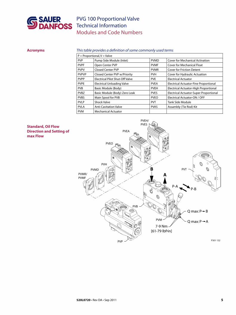
Standard, Oil Flow Direction and Setting of max Flow
This table provides a definition of some commonly used termsP = Proportional, V = Valve
PVP Pump Side Module (Inlet) PVMD Cover for Mechanical Activation
PVPF Open Center PVP PVMF Cover for Mechanical Float
PVPV Closed Center PVP PVMR Cover for Friction Detent
PVPVP Closed Center PVP w/Priority PVH Cover for Hydraulic Actuation
PVPP Electrical Pilot Shut-Off Valve PVE Electrical Actuator
PVPE Electrical Unloading Valve PVEA Electrical Actuator-Fine Proportional
PVB Basic Module (Body) PVEH Electrical Actuator-High Proportional
PVBZ Basic Module (Body) Zero Leak PVES Electrical Actuator-Super Proportional
PVBS Main Spool for PVB PVEO Electrical Actuator-ON / OFF
PVLP Shock Valve PVT Tank Side Module
PVLA Anti-Cavitation Valve PVAS Assambly (Tie Rod) Kit
PVM Mechanical Actuator
Modules and Code Numbers
P301 132
PVEH/PVES
PVEA
PVEO
PVH
PVMD
PVMR/PVMF
PVP
PVM
PVB
PVTBA
P-AP-B
7-9 Nm[61-79 lbf•in]
Q max: P B
Q max: P A
6 520L0720 • Rev DA • Sep 2011
PVG 100 Proportional ValveTechnical InformationGeneral
General Valve systemPVG 100 is a hydraulic load sensing valve, designed to fulfill customer requirements.From a simple load sensing directional valve to an advanced electro hydraulic controlled load independent proportional valve.The PVG 100 modular system makes it possible to build up a valve group to fulfill customer requirements. The compact external dimensions of the valve remains unchanged whatever combination is specified.
General features PVG 100• Load independent flow control
• Oil flow to an individual function is independent of the load on this function• Oil flow to one function is independent of the load pressure of other functions
• Anti – saturation (flow sharing)• In case of saturation, pump flow is shared between all functions, independent of load.
• Good regulation characteristics • Up to 8 PVB 100 basic modules per valve group• Up to 10 PVB 100/32 basic modules per valve group• BSP and UNF connection threads
PVP - Pump side module • Build in load sense relief valve • System pressure up to 350 bar (5075 psi) • Accumulator gauge connection• Full Flow dump valve (open center only) • Pressure gauge connection• Pilot supply shut off • Pilot gauge connection• Versions
• Open center version for systems with fixed displacement pumps • Closed center versions for systems with variable displacement pump• Integrated priority valve
• Integrated pilot supply valve
PVB – basic module• Integrated pilot operated check valves in A and B work ports for low internal leakage• Integrated pressure compensator • Interchangeable spools• Depending on requirements the basic module can be supplied with :
• Shock/suction valves• Different spools
Actuation modulesThe basic module is always fitted with mechanical actuator PVM, which can be combined with the following as required:• Electrical actuator
• PVES – super proportional• PVEH – proportional high• PVED – Can-bus interface• PVEA – proportional, fine• PVEO – ON/OFF
• PVH, cover for hydraulic actuation• PVMD, for mechanical actuation• PVMR, for friction detent*• PVMF, for mechanical float* * Not compatible with PO check modules
7520L0720 • Rev DA • Sep 2011
PVG 100 Proportional ValveTechnical InformationFunction PVG 100
PVG 100 Valve Group with Open Center PVPF
PVG 100 Valve Group with Closed Center PVPV
PVG100 Basic Modules
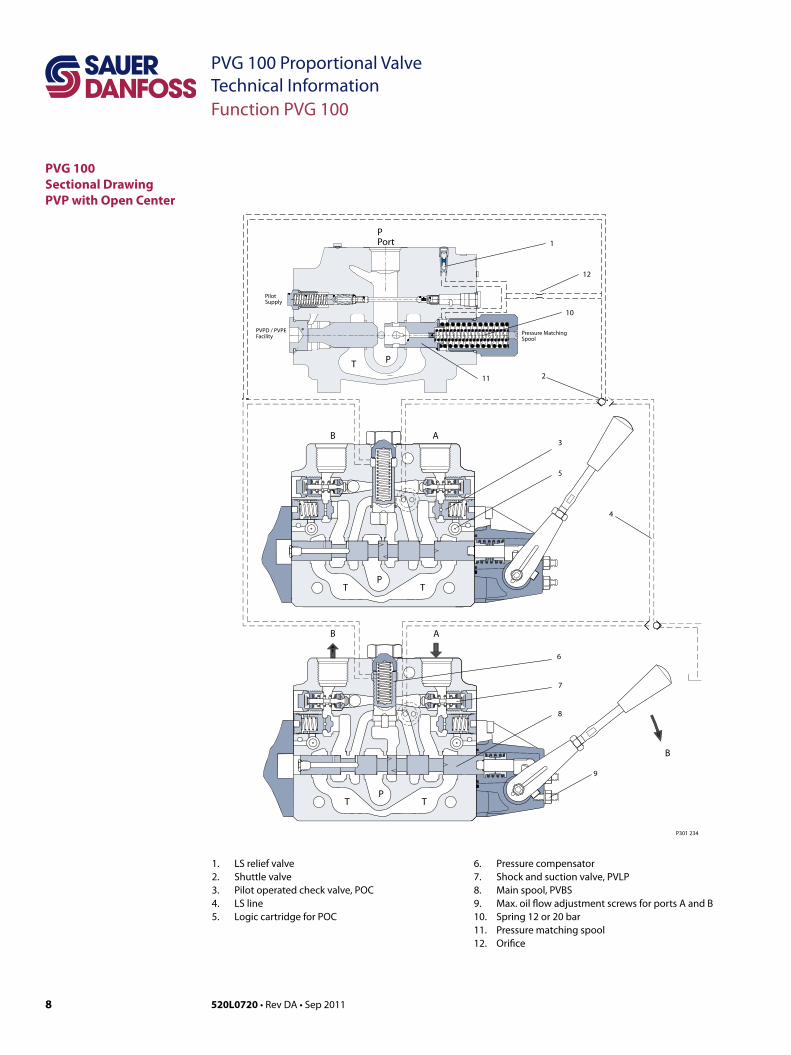
When the pump is started and the main spools in the individual basic modules are in the neutral position, oil flows from the pump, through connection P, across the pressure matching spool to tank. The oil flow led across the pressure matching spool determines the pump pressure (stand-by pressure).When one or more of the main spools are actuated, the highest load pressure is fed through the shuttle valve circuit to the spring chamber behind the pressure matching spool, and completely or partially closes the connection to tank.Pump pressure is applied to the opposite side of the pressure matching spool. The pressure relief valve will open should the load pressure exceed the set value, diverting pump flow back to tank.
In load sensing systems the load pressure is led to the pump regulator via the LS connection.In the neutral position the pump control sets the displacement so that leakage in the system is compensated for, to maintain the set stand-by pressure (pump margin).When a main spool is actuated the pump regulator will adjust the displacement so that the set differential pressure between P and LS is maintained.The pressure relief valve in PVP should be set at a pressure af approx. 20 bar [290 psi] below maximum system pressure (set on the pump or external pressure relief valve).
In a pressure-compensated basic module the compensator maintains a constant pressure drop across the main spool – both when the load changes and when a module with a higher load pressure is actuated.
Besides independent flow the other advantage of post-compensated work sections is the ability to control multifunction operation when flow demand exceeds pump capacity. This means that all work sections will continue to function regardless of differences in their load and regardless of the pump flow. The flow relationships specified between functions will be maintained over the full flow range of the pump.
The shock valves PVLP with fixed setting and the suction valves PVLA on ports A and B are used for the protection of the individual working function against overload and/or cavitation.
With post-compensated valves, the rating of the A- and B work-port flow will depend on the pressure drop across the main spool PVBS. In open center systems, this pressure drop (standby-pressure) is generated by the volume of pump flow led to tank across the pressure adjusting spool in the inlet PVPF. Since the pressure drop varies with pump flow volume led to tank, also the A- and B work-port flow will vary (see further details page 21). In closed center systems, the pressure drop across the main spool equals the standby setting of the pump, measured at the P-port of the valve. The A and B work port flow will remain unchanged as long as the standby is unchanged.
8 520L0720 • Rev DA • Sep 2011
PVG 100 Proportional ValveTechnical Information
PVG 100Sectional DrawingPVP with Open Center
1. LS relief valve 2. Shuttle valve 3. Pilot operated check valve, POC 4. LS line 5. Logic cartridge for POC
6. Pressure compensator 7. Shock and suction valve, PVLP 8. Main spool, PVBS 9. Max. oil flow adjustment screws for ports A and B10. Spring 12 or 20 bar11. Pressure matching spool12. Orifice
Function PVG 100
B A
B A
B
9
8
7
6
3
5
4
T TP
T TP
1
10
12
11 2T P
PPort
PVPD / PVPEFacility
PilotSupply
Pressure MatchingSpool
P301 234
9520L0720 • Rev DA • Sep 2011
PVG 100 Proportional ValveTechnical Information
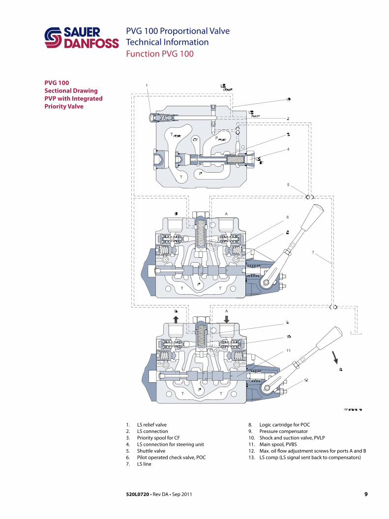
PVG 100Sectional DrawingPVP with Integrated Priority Valve
1. LS relief valve 2. LS connection3. Priority spool for CF4. LS connection for steering unit5. Shuttle valve 6. Pilot operated check valve, POC 7. LS line
8. Logic cartridge for POC9. Pressure compensator 10. Shock and suction valve, PVLP 11. Main spool, PVBS 12. Max. oil flow adjustment screws for ports A and B13. LS comp (LS signal sent back to compensators)
Function PVG 100

10 520L0720 • Rev DA • Sep 2011
PVG 100 Proportional ValveTechnical InformationNotes
Notes
11520L0720 • Rev DA • Sep 2011
PVG 100 Proportional ValveTechnical InformationTechnical Data
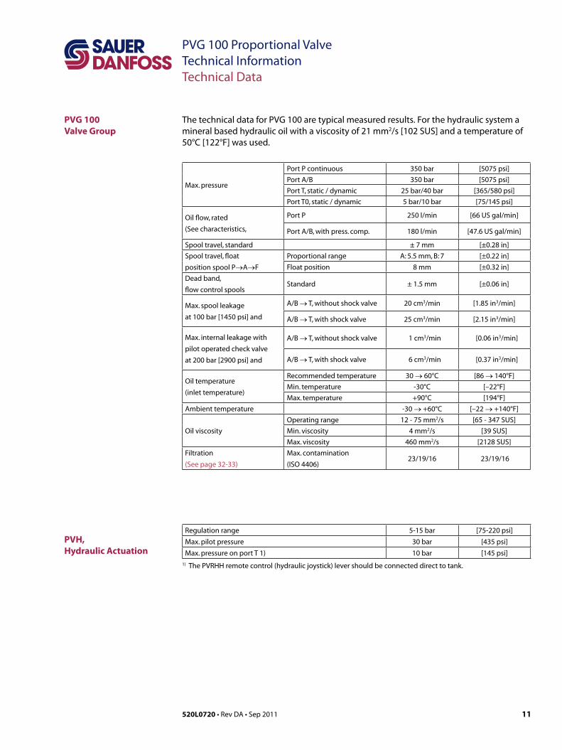
PVG 100Valve Group
PVH, Hydraulic Actuation
The technical data for PVG 100 are typical measured results. For the hydraulic system a mineral based hydraulic oil with a viscosity of 21 mm2/s [102 SUS] and a temperature of 50°C [122°F] was used.
Regulation range 5-15 bar [75-220 psi]
Max. pilot pressure 30 bar [435 psi]
Max. pressure on port T 1) 10 bar [145 psi]
Max. pressure
Port P continuous 350 bar [5075 psi]
Port A/B 350 bar [5075 psi]
Port T, static / dynamic 25 bar/40 bar [365/580 psi]
Port T0, static / dynamic 5 bar/10 bar [75/145 psi]
Oil flow, rated
(See characteristics,
Port P 250 l/min [66 US gal/min]
Port A/B, with press. comp. 180 l/min [47.6 US gal/min]
Spool travel, standard ± 7 mm [±0.28 in]
Spool travel, float
position spool P→A→FProportional range A: 5.5 mm, B: 7 [±0.22 in]
Float position 8 mm [±0.32 in]
Dead band,
flow control spoolsStandard ± 1.5 mm [±0.06 in]
Max. spool leakage
at 100 bar [1450 psi] and
A/B → T, without shock valve 20 cm3/min [1.85 in3/min]
A/B → T, with shock valve 25 cm3/min [2.15 in3/min]
Max. internal leakage with
pilot operated check valve
at 200 bar [2900 psi] and
A/B → T, without shock valve 1 cm3/min [0.06 in3/min]
A/B → T, with shock valve 6 cm3/min [0.37 in3/min]
Oil temperature
(inlet temperature)
Recommended temperature 30 → 60°C [86 → 140°F]
Min. temperature -30°C [–22°F]
Max. temperature +90°C [194°F]
Ambient temperature -30 → +60°C [–22 → +140°F]
Oil viscosity
Operating range 12 - 75 mm2/s [65 - 347 SUS]
Min. viscosity 4 mm2/s [39 SUS]
Max. viscosity 460 mm2/s [2128 SUS]
Filtration
(See page 32-33)
Max. contamination
(ISO 4406)23/19/16 23/19/16
1) The PVRHH remote control (hydraulic joystick) lever should be connected direct to tank.
12 520L0720 • Rev DA • Sep 2011
PVG 100 Proportional ValveTechnical Information
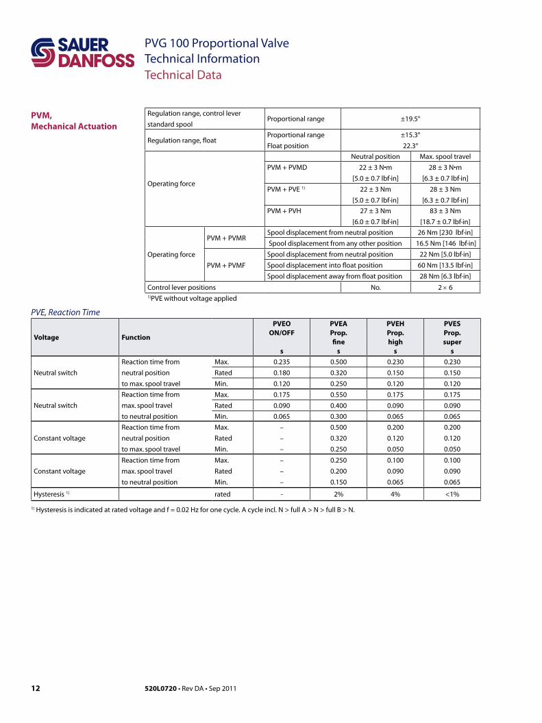
PVM,Mechanical Actuation
PVE, Reaction Time
Regulation range, control leverstandard spool
Proportional range ±19.5°
Regulation range, floatProportional rangeFloat position
±15.3°22.3°
Operating force
Neutral position Max. spool travelPVM + PVMD 22 ± 3 N•m
[5.0 ± 0.7 lbf·in]
28 ± 3 N•m
[6.3 ± 0.7 lbf·in]
PVM + PVE 1) 22 ± 3 Nm
[5.0 ± 0.7 lbf·in]
28 ± 3 Nm
[6.3 ± 0.7 lbf·in]
PVM + PVH 27 ± 3 Nm
[6.0 ± 0.7 lbf·in]
83 ± 3 Nm
[18.7 ± 0.7 lbf·in]
Operating force
PVM + PVMRSpool displacement from neutral position 26 Nm [230 lbf·in]
Spool displacement from any other position 16.5 Nm [146 lbf·in]
PVM + PVMF
Spool displacement from neutral position 22 Nm [5.0 lbf·in]
Spool displacement into float position 60 Nm [13.5 lbf·in]
Spool displacement away from float position 28 Nm [6.3 lbf·in]
Control lever positions No. 2 × 61)PVE without voltage applied
Technical Data
Voltage Function
PVEOON/OFF
s
PVEAProp.fine
s
PVEHProp.high
s
PVES Prop.super
s
Neutral switch
Reaction time from
neutral position
to max. spool travel
Max. 0.235 0.500 0.230 0.230
Rated 0.180 0.320 0.150 0.150
Min. 0.120 0.250 0.120 0.120
Neutral switch
Reaction time from
max. spool travel
to neutral position
Max. 0.175 0.550 0.175 0.175
Rated 0.090 0.400 0.090 0.090
Min. 0.065 0.300 0.065 0.065
Constant voltage
Reaction time from
neutral position
to max. spool travel
Max.
Rated
Min.
–
–
–
0.500
0.320
0.250
0.200
0.120
0.050
0.200
0.120
0.050
Constant voltage
Reaction time from
max. spool travel
to neutral position
Max.
Rated
Min.
–
–
–
0.250
0.200
0.150
0.100
0.090
0.065
0.100
0.090
0.065
Hysteresis 1) rated - 2% 4% <1%
1) Hysteresis is indicated at rated voltage and f = 0.02 Hz for one cycle. A cycle incl. N > full A > N > full B > N.
13520L0720 • Rev DA • Sep 2011
PVG 100 Proportional ValveTechnical Information
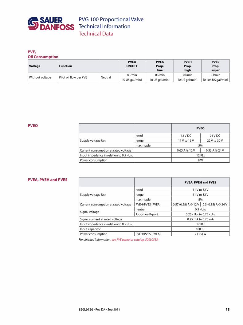
PVE,Oil Consumption
Voltage FunctionPVEO
ON/OFFPVEAProp.fine
PVEHProp.high
PVES Prop.super
Without voltage Pilot oil flow per PVE Neutral0 l/min
[0 US gal/min]
0 l/min
[0 US gal/min]
0 l/min
[0 US gal/min]
0 l/min
[0.106 US gal/min]
Technical Data
PVEO
Supply voltage UDC
rated 12 V DC 24 V DC
range 11 V to 15 V 22 V to 30 V
max. ripple 5%
Current consumption at rated voltage 0.65 A @ 12 V 0.33 A @ 24 V
Input impedance in relation to 0.5 • UDC 12 KΩPower consumption 8 W
PVEA, PVEH and PVES
Supply voltage UDC
rated 11 V to 32 V
range 11 V to 32 V
max. ripple 5%
Current consumption at rated voltage PVEH/PVES (PVEA) 0.57 (0.28) A @ 12 V 0.3 (0.15) A @ 24 V
Signal voltage neutral 0.5 • UDC
A-port ↔ B-port 0.25 • UDC to 0.75 • UDC
Signal currrent at rated voltage 0.25 mA to 0.70 mA
Input impedance in relation to 0.5 • UDC 12 KΩInput capacitor 100 ηF
Power consumption PVEH/PVES (PVEA) 7 (3.5) W
For detailed information, see PVE actuator catalog, 520L0553
PVEO
PVEA, PVEH and PVES
14 520L0720 • Rev DA • Sep 2011
PVG 100 Proportional ValveTechnical InformationModules and Code Numbers
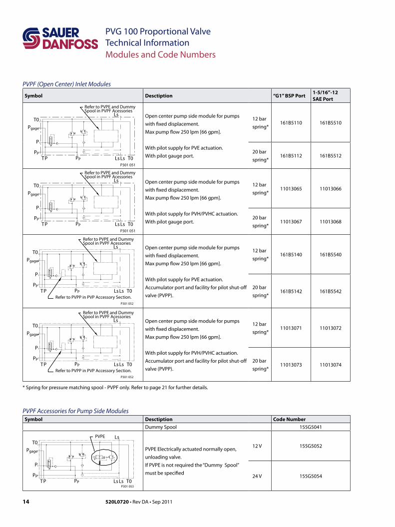
PVPF (Open Center) Inlet Modules
Symbol Desctiption “G1” BSP Port1-5/16”-12SAE Port
T0
P
Pgage
PPPP T0LsLsTP
LsRefer to PVPE and Dummy Spool in PVPF Acessories
P301 051
Open center pump side module for pumps
with fixed displacement.
Max pump flow 250 lpm [66 gpm].
With pilot supply for PVE actuation.
With pilot gauge port.
12 bar
spring*161B5110 161B5510
20 bar
spring*161B5112 161B5512
T0
P
Pgage
PPPP T0LsLsTP
LsRefer to PVPE and Dummy Spool in PVPF Acessories
P301 051
Open center pump side module for pumps
with fixed displacement.
Max pump flow 250 lpm [66 gpm].
With pilot supply for PVH/PVHC actuation.
With pilot gauge port.
12 bar
spring*11013065 11013066
20 bar
spring*11013067 11013068
P301 052
T0
P
Pgage
PPPP T0LsLsTP
Refer to PVPP in PVP Accessory Section.
LsRefer to PVPE and Dummy Spool in PVPF Acessories
Open center pump side module for pumps
with fixed displacement.
Max pump flow 250 lpm [66 gpm].
With pilot supply for PVE actuation.
Accumulator port and facility for pilot shut-off
valve (PVPP).
12 bar
spring*161B5140 161B5540
20 bar
spring*161B5142 161B5542
P301 052
T0
P
Pgage
PPPP T0LsLsTP
Refer to PVPP in PVP Accessory Section.
LsRefer to PVPE and Dummy Spool in PVPF Acessories
Open center pump side module for pumps
with fixed displacement.
Max pump flow 250 lpm [66 gpm].
With pilot supply for PVH/PVHC actuation.
Accumulator port and facility for pilot shut-off
valve (PVPP).
12 bar
spring*11013071 11013072
20 bar
spring*11013073 11013074
* Spring for pressure matching spool - PVPF only. Refer to page 21 for further details.
PVPF Accessories for Pump Side ModulesSymbol Desctiption Code Number
Dummy Spool 155G5041
P301 053
T0
P
Pgage
PPPP T0LsLsTP
PVPE Ls
PVPE Electrically actuated normally open,
unloading valve.
If PVPE is not required the “Dummy Spool”
must be specified
12 V 155G5052
24 V 155G5054
15520L0720 • Rev DA • Sep 2011
PVG 100 Proportional ValveTechnical InformationModules and Code Numbers
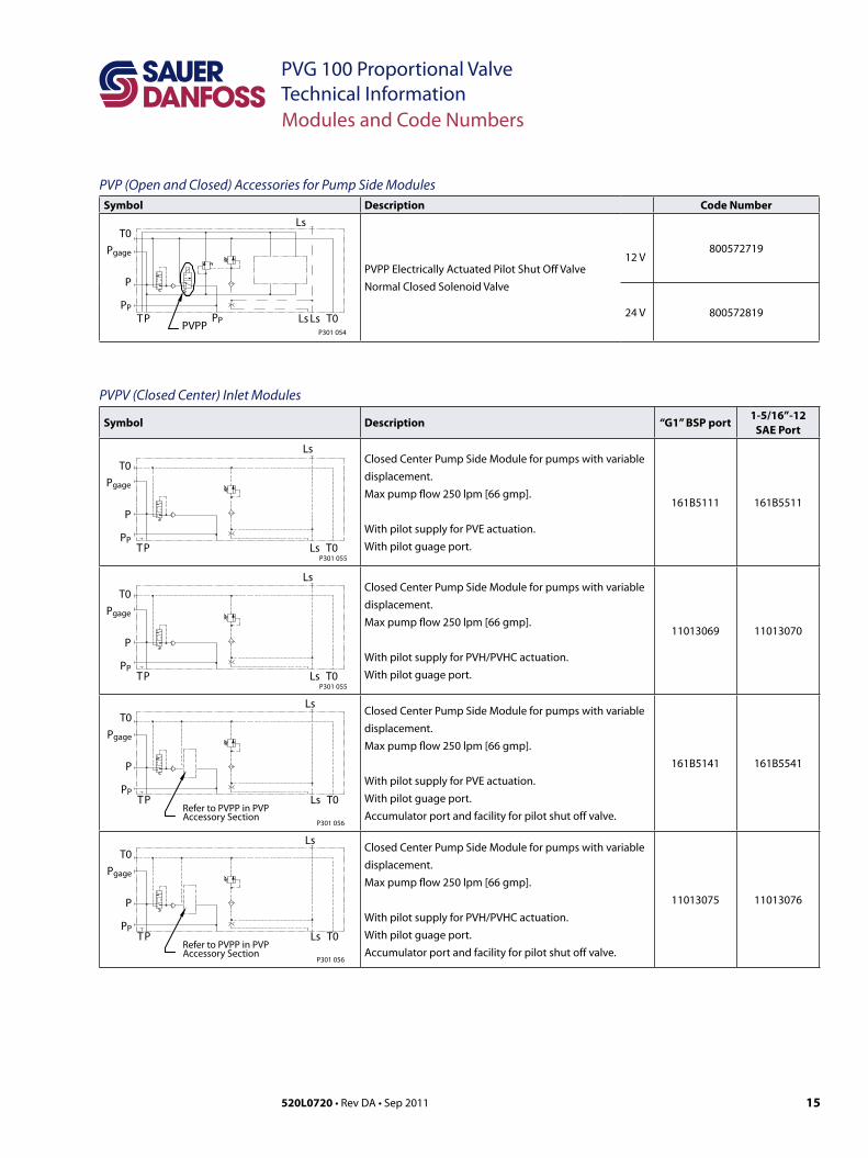
PVP (Open and Closed) Accessories for Pump Side ModulesSymbol Description Code Number
T0
P
Pgage
PPPP T0LsLsTP
Ls
P301 054PVPP
PVPP Electrically Actuated Pilot Shut Off Valve
Normal Closed Solenoid Valve
12 V800572719
24 V 800572819
PVPV (Closed Center) Inlet Modules
Symbol Description “G1” BSP port1-5/16”-12
SAE Port
P301 055
T0
P
Pgage
PPT0LsTP
LsClosed Center Pump Side Module for pumps with variable
displacement.
Max pump flow 250 lpm [66 gmp].
With pilot supply for PVE actuation.
With pilot guage port.
161B5111 161B5511
P301 055
T0
P
Pgage
PPT0LsTP
LsClosed Center Pump Side Module for pumps with variable
displacement.
Max pump flow 250 lpm [66 gmp].
With pilot supply for PVH/PVHC actuation.
With pilot guage port.
11013069 11013070
P301 056
T0
P
Pgage
PPT0LsTP
Ls
Refer to PVPP in PVP Accessory Section
Closed Center Pump Side Module for pumps with variable
displacement.
Max pump flow 250 lpm [66 gmp].
With pilot supply for PVE actuation.
With pilot guage port.
Accumulator port and facility for pilot shut off valve.
161B5141 161B5541
P301 056
T0
P
Pgage
PPT0LsTP
Ls
Refer to PVPP in PVP Accessory Section
Closed Center Pump Side Module for pumps with variable
displacement.
Max pump flow 250 lpm [66 gmp].
With pilot supply for PVH/PVHC actuation.
With pilot guage port.
Accumulator port and facility for pilot shut off valve.
11013075 11013076
16 520L0720 • Rev DA • Sep 2011
PVG 100 Proportional ValveTechnical InformationModules and Code Numbers
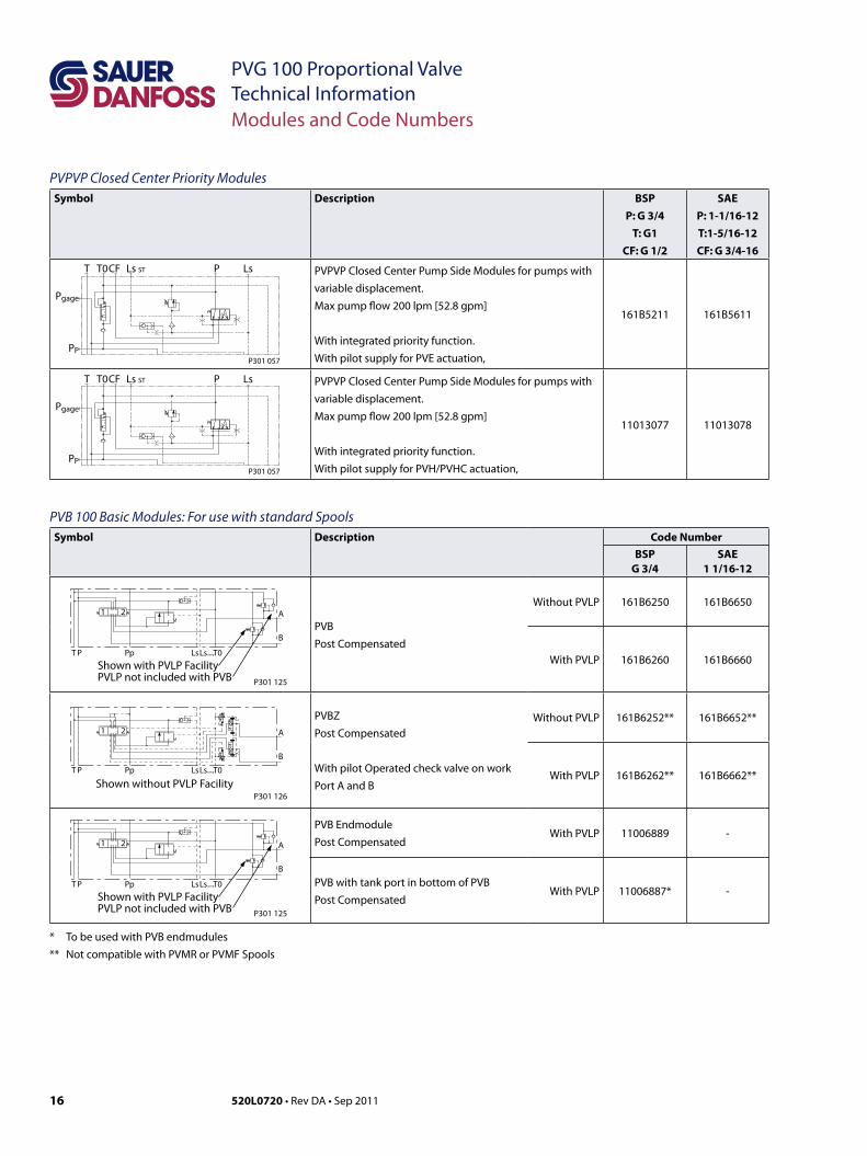
PVPVP Closed Center Priority ModulesSymbol Description BSP
P: G 3/4
T: G1
CF: G 1/2
SAEP: 1-1/16-12
T:1-5/16-12
CF: G 3/4-16
T0
Pgage
PP
CF Ls STT P Ls
P301 057
PVPVP Closed Center Pump Side Modules for pumps with
variable displacement.
Max pump flow 200 lpm [52.8 gpm]
With integrated priority function.
With pilot supply for PVE actuation,
161B5211 161B5611
T0
Pgage
PP
CF Ls STT P Ls
P301 057
PVPVP Closed Center Pump Side Modules for pumps with
variable displacement.
Max pump flow 200 lpm [52.8 gpm]
With integrated priority function.
With pilot supply for PVH/PVHC actuation,
11013077 11013078
PVB 100 Basic Modules: For use with standard SpoolsSymbol Description Code Number
BSPG 3/4
SAE1 1/16-12
P301 125
Shown with PVLP FacilityPVLP not included with PVB
1 2 A
B
T LsLscompT0PpP
PVB
Post Compensated
Without PVLP 161B6250 161B6650
With PVLP 161B6260 161B6660
P301 126Shown without PVLP Facility
1 2 A
B
T LsLscompT0PpP
PVBZ
Post Compensated
With pilot Operated check valve on work
Port A and B
Without PVLP 161B6252** 161B6652**
With PVLP 161B6262** 161B6662**
P301 125
Shown with PVLP FacilityPVLP not included with PVB
1 2 A
B
T LsLscompT0PpP
PVB Endmodule
Post CompensatedWith PVLP 11006889 -
PVB with tank port in bottom of PVB
Post CompensatedWith PVLP 11006887* -
* To be used with PVB endmudules** Not compatible with PVMR or PVMF Spools
17520L0720 • Rev DA • Sep 2011
PVG 100 Proportional ValveTechnical InformationModules and Code Numbers
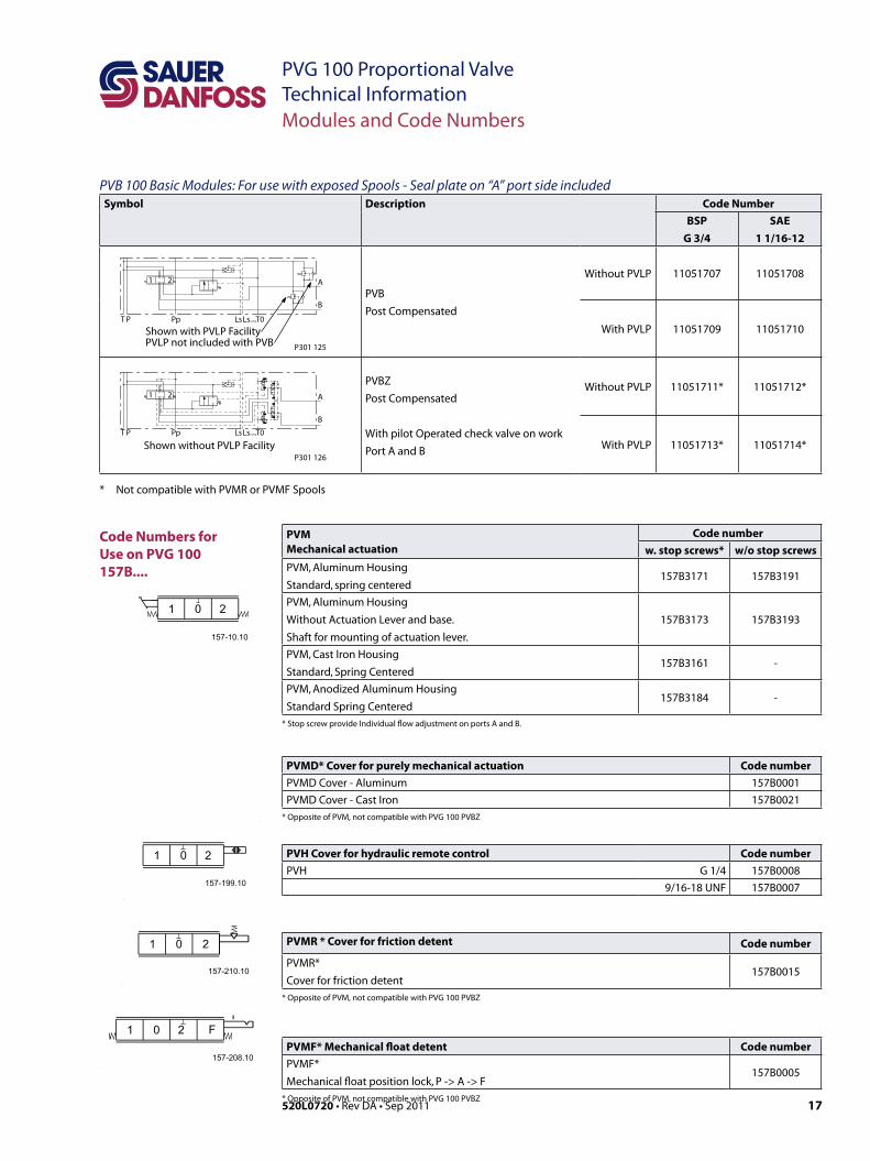
Code Numbers for Use on PVG 100 157B....
PVMMechanical actuation
Code numberw. stop screws* w/o stop screws
PVM, Aluminum Housing
Standard, spring centered157B3171 157B3191
PVM, Aluminum Housing
Without Actuation Lever and base.
Shaft for mounting of actuation lever.
157B3173 157B3193
PVM, Cast Iron Housing
Standard, Spring Centered157B3161 -
PVM, Anodized Aluminum Housing
Standard Spring Centered157B3184 -
* Stop screw provide Individual flow adjustment on ports A and B.
PVMD* Cover for purely mechanical actuation Code numberPVMD Cover - Aluminum 157B0001
PVMD Cover - Cast Iron 157B0021
* Opposite of PVM, not compatible with PVG 100 PVBZ
PVH Cover for hydraulic remote control Code numberPVH G 1/4 157B0008
9/16-18 UNF 157B0007
PVMR * Cover for friction detent Code number
PVMR*
Cover for friction detent157B0015
* Opposite of PVM, not compatible with PVG 100 PVBZ
PVMF* Mechanical float detent Code numberPVMF*
Mechanical float position lock, P -> A -> F157B0005
* Opposite of PVM, not compatible with PVG 100 PVBZ
PVB 100 Basic Modules: For use with exposed Spools - Seal plate on “A” port side includedSymbol Description Code Number
BSP
G 3/4
SAE
1 1/16-12
P301 125
Shown with PVLP FacilityPVLP not included with PVB
1 2 A
B
T LsLscompT0PpP
PVB
Post Compensated
Without PVLP 11051707 11051708
With PVLP 11051709 11051710
P301 126Shown without PVLP Facility
1 2 A
B
T LsLscompT0PpP
PVBZ
Post Compensated
With pilot Operated check valve on work
Port A and B
Without PVLP 11051711* 11051712*
With PVLP 11051713* 11051714*
* Not compatible with PVMR or PVMF Spools
18 520L0720 • Rev DA • Sep 2011
PVG 100 Proportional ValveTechnical InformationModules and Code Numbers
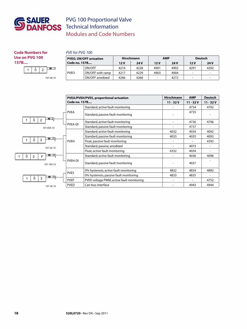
Code Numbers for Use on PVG 100157B....
PVE for PVG 100PVEO, ON/OFF actuationCode no. 157B....
Hirschmann AMP Deutsch12 V 24 V 12 V 24 V 12 V 24 V
PVEO
ON/OFF 4216 4228 4901 4902 4291 4292
ON/OFF with ramp 4217 4229 4903 4904 - -
ON/OFF anodized 4266 4268 - 4272 - -
PVEA/PVEH/PVES, proportional actuationCode no. 157B....
Hirschmann AMP Deutsch11 - 32 V 11 - 32 V 11 - 32 V
PVEA
Standard, active fault monitoring - 4734 4792
Standard, passive fault monitoring -4735
-
PVEA-DIStandard, active fault monitoring - 4736 4796
Standard, passive fault monitoring - 4737 -
PVEH
Standard, active fault monitoring 4032 4034 4092
Standard, passive fault monitoring 4033 4035 4093
Float, passive fault monitoring - - 4392
Standard, passive, anodized - 4073 -
Float, active fault monitoring 4332 4034 -
PVEH-DI
Standard, active fault monitoring - 4036 4096
Standard, passive fault monitoring - 4037-
PVES0% hysteresis, active fault monitoring 4832 4834 4892
0% hysteresis, passive fault monitoring 4833 4835 -
PVEP PVEP, voltage PWM, active fault monitoring - - 4752
PVED Can-bus interface - 4943 4944
19520L0720 • Rev DA • Sep 2011
PVG 100 Proportional ValveTechnical Information
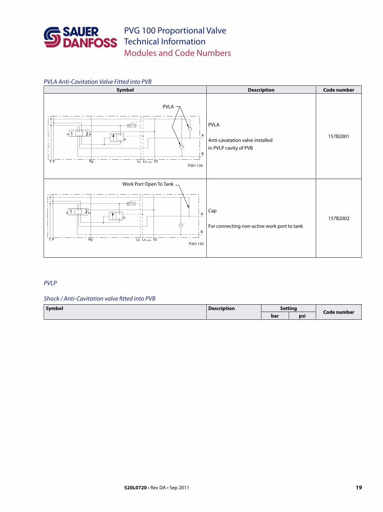
PVLA Anti-Cavitation Valve Fitted into PVBSymbol Description Code number
Pp T0Ls Ls compT P
PVLA
A
B
1 2
P301 134
PVLA
Anti-cavatation valve installed
in PVLP cavity of PVB
157B2001
T P Pp T0Ls Ls comp
Work Port Open To Tank
A
B
1 2
P301 135
Cap
For connecting non-active work port to tank
157B2002
PVLP
Shock / Anti-Cavitation valve fitted into PVBSymbol Description Setting
Code numberbar psi
Modules and Code Numbers
20 520L0720 • Rev DA • Sep 2011
PVG 100 Proportional ValveTechnical InformationModules and Code Numbers
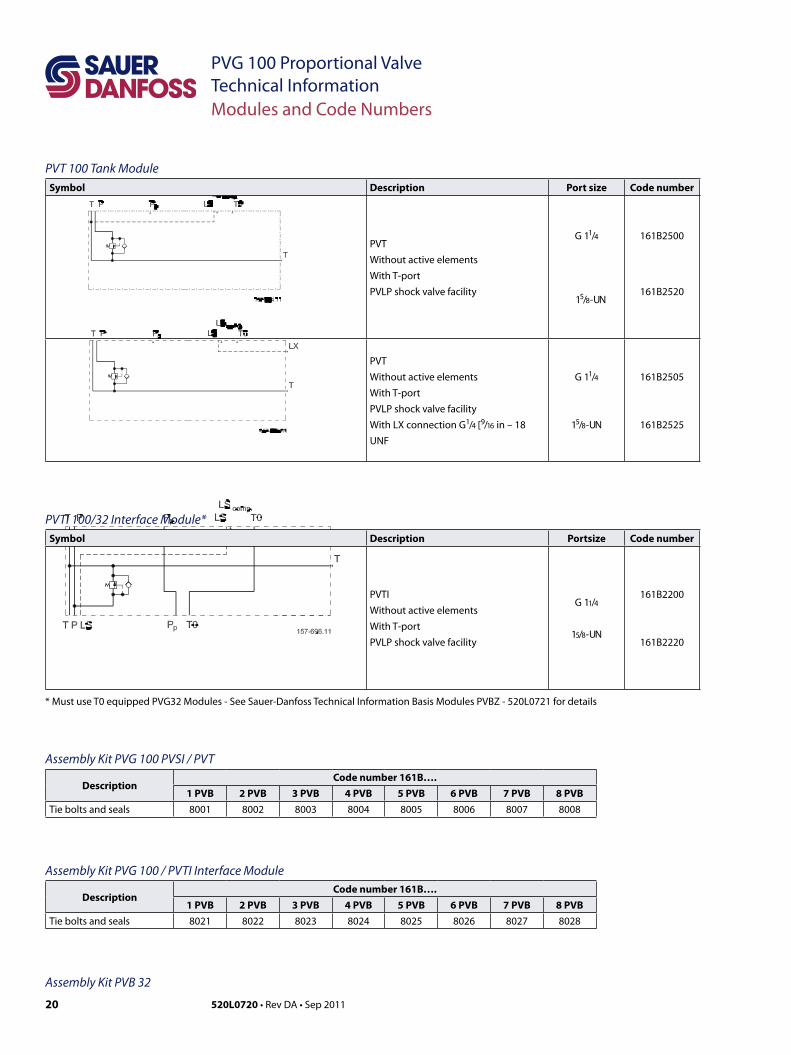
PVT 100 Tank ModuleSymbol Description Port size Code number
PVT
Without active elements
With T-port
PVLP shock valve facility
G 11/4
15/8 - UN
161B2500
161B2520
PVT
Without active elements
With T-port
PVLP shock valve facility
With LX connection G1/4 [ 9/16 in – 18
UNF
G 11/4
15/8 - UN
161B2505
161B2525
PVTI 100/32 Interface Module*Symbol Description Portsize Code number
PVTI
Without active elements
With T-port
PVLP shock valve facility
G 11/4
15/8 - UN
161B2200
161B2220
* Must use T0 equipped PVG32 Modules - See Sauer-Danfoss Technical Information Basis Modules PVBZ - 520L0721 for details
Assembly Kit PVG 100 PVSI / PVT
DescriptionCode number 161B….
1 PVB 2 PVB 3 PVB 4 PVB 5 PVB 6 PVB 7 PVB 8 PVBTie bolts and seals 8001 8002 8003 8004 8005 8006 8007 8008
Assembly Kit PVG 100 / PVTI Interface Module
DescriptionCode number 161B….
1 PVB 2 PVB 3 PVB 4 PVB 5 PVB 6 PVB 7 PVB 8 PVBTie bolts and seals 8021 8022 8023 8024 8025 8026 8027 8028
Assembly Kit PVB 32
21520L0720 • Rev DA • Sep 2011
PVG 100 Proportional ValveTechnical InformationTechnical Characteristics
General
PVPF only Pump Side Module
Open Center Flow Rating
The characteristics in this catalog are typical measured results.During measuring a mineral based hydraulic oil with a viscosity of 21 mm2/s [102 SUS] at a temperature of 50°C [122°F] was used.
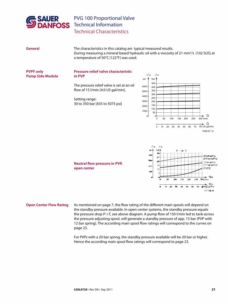
Pressure relief valve characteristic in PVP
The pressure relief valve is set at an oil flow of 15 l/min [4.0 US gal/min].
Setting range: 30 to 350 bar [435 to 5075 psi]
Neutral flow pressure in PVP, open center
As mentioned on page 7, the flow rating of the different main spools will depend on the standby pressure available. In open center systems, the standby pressure equals the pressure drop P->T, see above diagram. A pump flow of 150 l/min led to tank across the pressure adjusting spool, will generate a standby pressure of app. 15 bar (PVP with 12 bar spring). The according main spool flow ratings will correspond to the curves on page 23.
For PVPs with a 20 bar spring, the standby pressure available will be 20 bar or higher. Hence the according main spool flow ratings will correspond to page 23.
22 520L0720 • Rev DA • Sep 2011
PVG 100 Proportional ValveTechnical InformationModules and Code Numbers
Closed Center Flow Rating: Ls Pumps
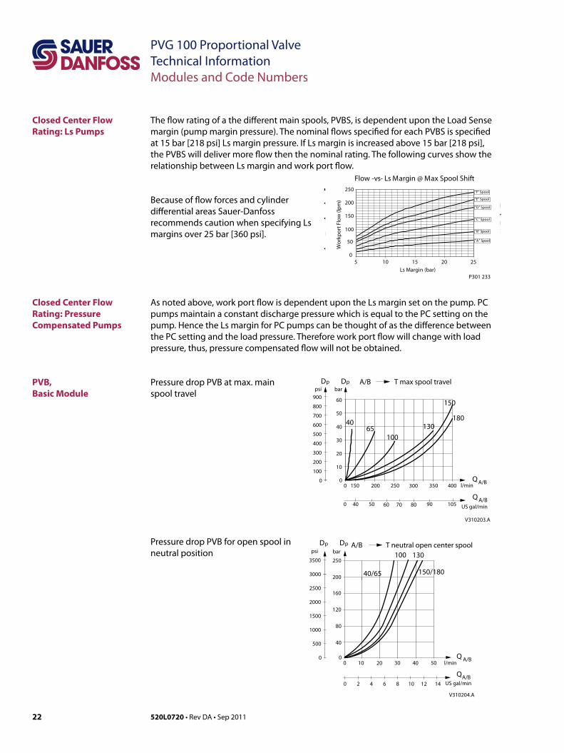
The flow rating of a the different main spools, PVBS, is dependent upon the Load Sense margin (pump margin pressure). The nominal flows specified for each PVBS is specified at 15 bar [218 psi] Ls margin pressure. If Ls margin is increased above 15 bar [218 psi], the PVBS will deliver more flow then the nominal rating. The following curves show the relationship between Ls margin and work port flow.
Closed Center Flow Rating: Pressure Compensated Pumps
As noted above, work port flow is dependent upon the Ls margin set on the pump. PC pumps maintain a constant discharge pressure which is equal to the PC setting on the pump. Hence the Ls margin for PC pumps can be thought of as the difference between the PC setting and the load pressure. Therefore work port flow will change with load pressure, thus, pressure compensated flow will not be obtained.
Because of flow forces and cylinder differential areas Sauer-Danfoss recommends caution when specifying Ls margins over 25 bar [360 psi].
Flow -vs- Ls Margin @ Max Spool Shift
0
50
100
150
200
250
5 10 15 20 25Ls Margin (bar)
Wor
kpor
t Flo
w (l
pm)
"F" Spool
"E" Spool
"D" Spool
"C" Spool
"B" Spool
"A" Spool
P301 233
PVB, Basic Module
Pressure drop PVB at max. main spool travel
Pressure drop PVB for open spool in neutral position
l/min
30
2500
0 150 200
10
20
300 350
40
50
60
4065
100
150
130
400 A/BQ
V310203.A
US gal/min
Q A/B
psi bar
0
pp A/B T max spool travel
100
200
300
400
500
600
700
800
900
D D
180
700 50 10560 8040 90
0 100 20
40
80
30 40 50
160
120
200
l/min
p ppsi bar
0
500
1000
1500
2000
2500
3000
Q A/B
US gal/min86420 1410 12
QA/B
A/B T neutral open center spoolDD
V310204.A
250
40/65
100 130
150/180
3500
23520L0720 • Rev DA • Sep 2011
PVG 100 Proportional ValveTechnical InformationTechnical Characteristics
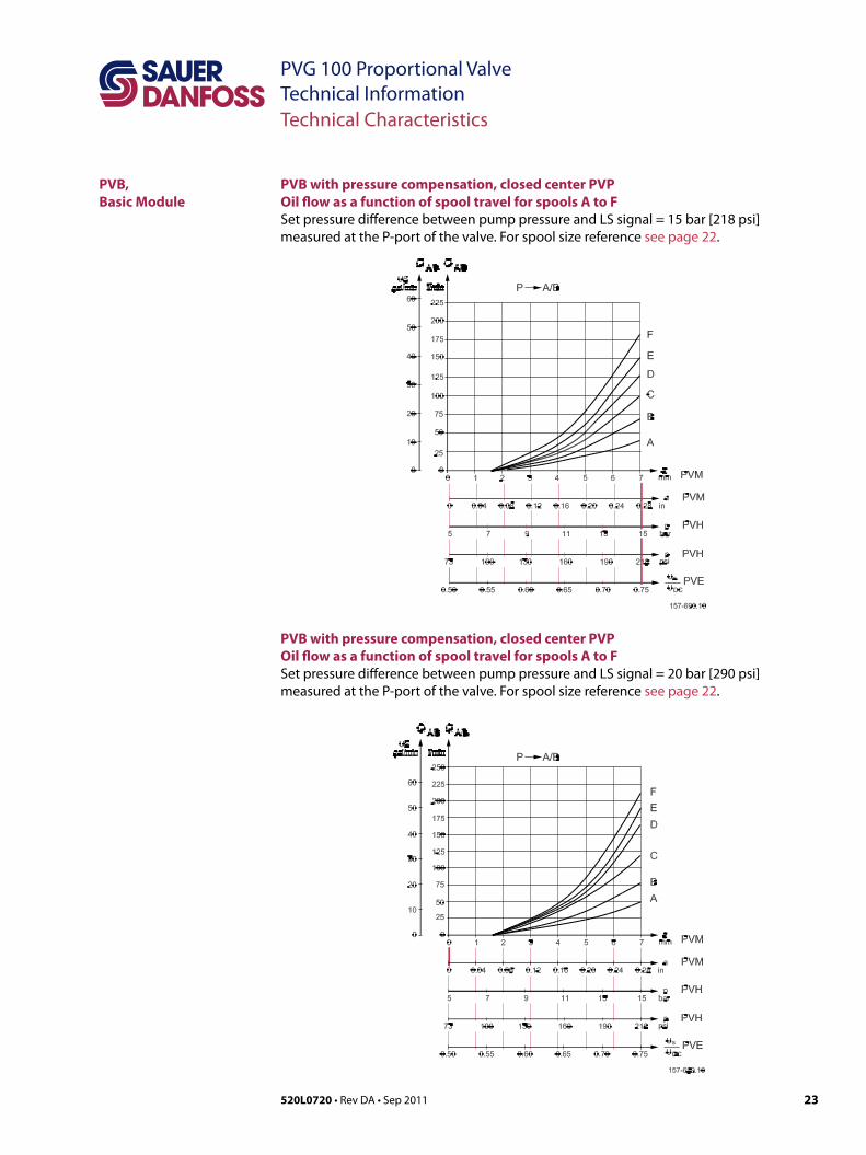
PVB with pressure compensation, closed center PVPOil flow as a function of spool travel for spools A to FSet pressure difference between pump pressure and LS signal = 15 bar [218 psi] measured at the P-port of the valve. For spool size reference see page 22.
PVB, Basic Module
PVB with pressure compensation, closed center PVPOil flow as a function of spool travel for spools A to FSet pressure difference between pump pressure and LS signal = 20 bar [290 psi]measured at the P-port of the valve. For spool size reference see page 22.
24 520L0720 • Rev DA • Sep 2011
PVG 100 Proportional ValveTechnical InformationTechnical Characteristics
PVLP,Shock and Suction Valve
PVLA,Suction Valve
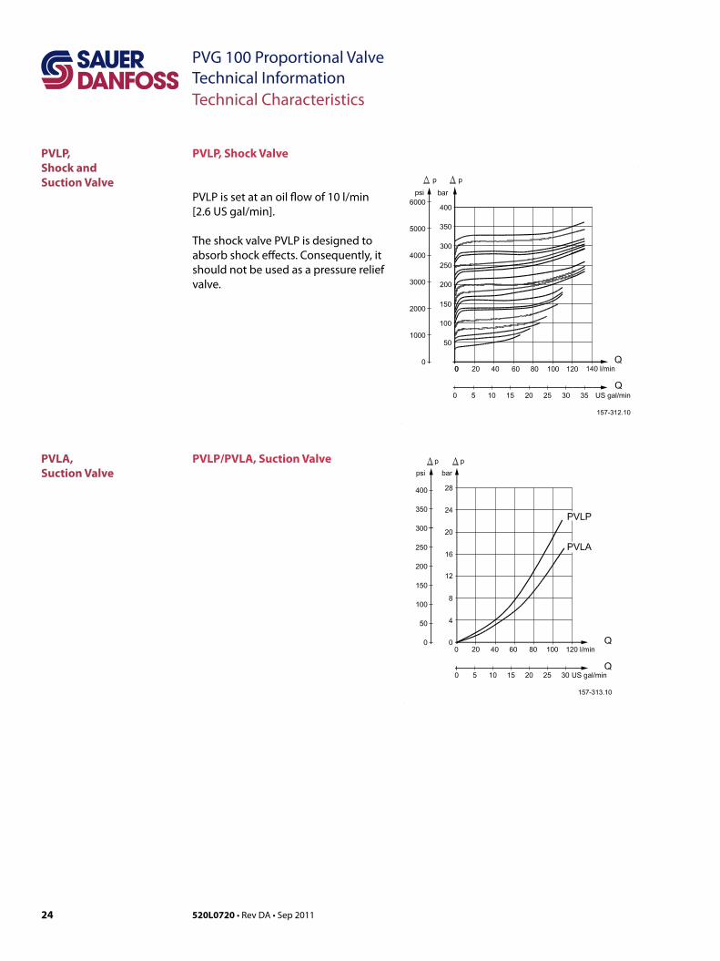
PVLP, Shock Valve
PVLP is set at an oil flow of 10 l/min [2.6 US gal/min].
The shock valve PVLP is designed to absorb shock effects. Consequently, it should not be used as a pressure relief valve.
PVLP/PVLA, Suction Valve
25520L0720 • Rev DA • Sep 2011
PVG 100 Proportional ValveTechnical InformationDimensions
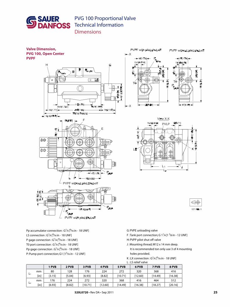
Valve Dimension,PVG 100, Open Center PVPF
1 PVB 2 PVB 3 PVB 4 PVB 5 PVB 6 PVB 7 PVB 8 PVB
L1 mm 80 128 176 224 272 320 368 416
[in] [3.15] [5.04] [6.93] [8.82] [10.71] [12.60] [14.49] [16.38]
L2 mm 176 224 272 320 368 416 464 512
[in] [6.93] [8.82] [10.71] [12.60] [14.49] [16.38] [18.27] [20.16]
G: PVPE unloading valve
F : Tank port connection; G 11/4 [1 5/8 in - 12 UNF]
H: PVPP pilot shut off valve
J : Mounting thread; M12 x 14 mm deep.
It is recommended ton only use 3 of 4 mounting
holes provided.
K : LX connection : G1/4 [9/16 in - 18 UNF]L : LS relief valve
Pp accumulator connection : G1/4 [9/16 in - 18 UNF]
LS connection : G1/4 [9/16 in - 18 UNF]
P gage connection : G1/4 [9/16 in - 18 UNF]
T0 port connection : G1/4 [9/16 in - 18 UNF]
Pp gage connection : G1/4 [9/16 in - 18 UNF]
P: Pump port connection; G1 [15/16 in - 12 UNF]
26 520L0720 • Rev DA • Sep 2011
PVG 100 Proportional ValveTechnical InformationDimensions
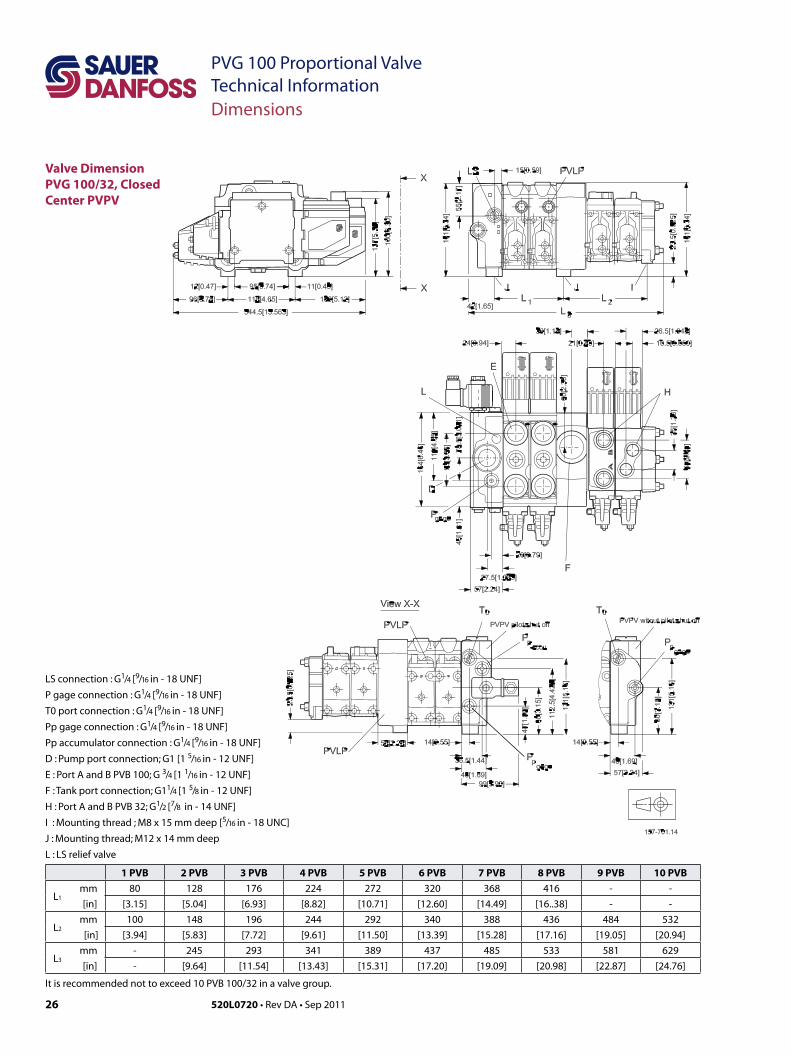
Valve Dimension PVG 100/32, Closed Center PVPV
LS connection : G1/4 [9/16 in - 18 UNF]
P gage connection : G1/4 [9/16 in - 18 UNF]
T0 port connection : G1/4 [9/16 in - 18 UNF]
Pp gage connection : G1/4 [9/16 in - 18 UNF]
Pp accumulator connection : G1/4 [9/16 in - 18 UNF]
D : Pump port connection; G1 [1 5/16 in - 12 UNF]
E : Port A and B PVB 100; G 3/4 [1 1/16 in - 12 UNF]
F : Tank port connection; G11/4 [1 5/8 in - 12 UNF]
H : Port A and B PVB 32; G1/2 [7/8 in - 14 UNF]
I : Mounting thread ; M8 x 15 mm deep [5/16 in - 18 UNC]
J : Mounting thread; M12 x 14 mm deep
L : LS relief valve
1 PVB 2 PVB 3 PVB 4 PVB 5 PVB 6 PVB 7 PVB 8 PVB 9 PVB 10 PVB
L1 mm 80 128 176 224 272 320 368 416 - -
[in] [3.15] [5.04] [6.93] [8.82] [10.71] [12.60] [14.49] [16..38] - -
L2 mm 100 148 196 244 292 340 388 436 484 532
[in] [3.94] [5.83] [7.72] [9.61] [11.50] [13.39] [15.28] [17.16] [19.05] [20.94]
L3 mm - 245 293 341 389 437 485 533 581 629
[in] - [9.64] [11.54] [13.43] [15.31] [17.20] [19.09] [20.98] [22.87] [24.76]
It is recommended not to exceed 10 PVB 100/32 in a valve group.
27520L0720 • Rev DA • Sep 2011
PVG 100 Proportional ValveTechnical Information
2
Dimensions
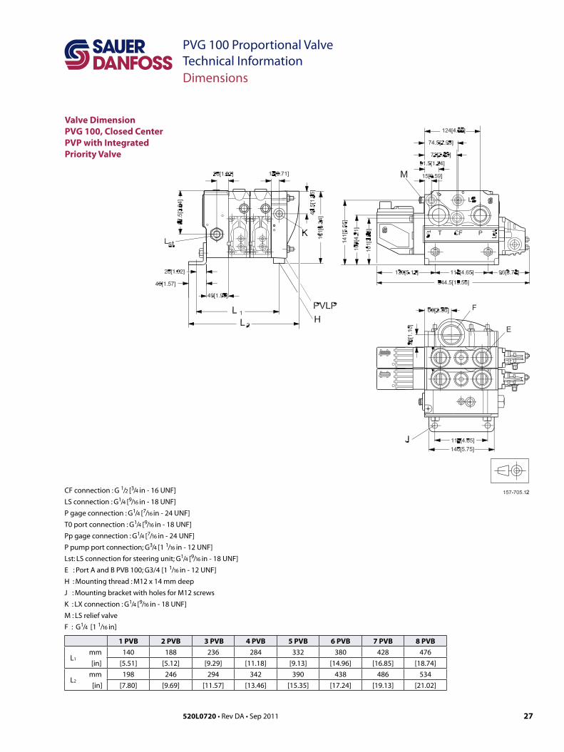
Valve Dimension PVG 100, Closed Center PVP with Integrated Priority Valve
1 PVB 2 PVB 3 PVB 4 PVB 5 PVB 6 PVB 7 PVB 8 PVB
L1 mm 140 188 236 284 332 380 428 476
[in] [5.51] [5.12] [9.29] [11.18] [9.13] [14.96] [16.85] [18.74]
L2 mm 198 246 294 342 390 438 486 534
[in] [7.80] [9.69] [11.57] [13.46] [15.35] [17.24] [19.13] [21.02]
CF connection : G 1/2 [3/4 in - 16 UNF]
LS connection : G1/4 [9/16 in - 18 UNF]
P gage connection : G1/4 [7/16 in - 24 UNF]
T0 port connection : G1/4 [9/16 in - 18 UNF]
Pp gage connection : G1/4 [7/16 in - 24 UNF]
P pump port connection; G3/4 [1 1/16 in - 12 UNF]
Lst: LS connection for steering unit; G1/4 [9/16 in - 18 UNF]
E : Port A and B PVB 100; G3/4 [1 1/16 in - 12 UNF]
H : Mounting thread : M12 x 14 mm deep
J : Mounting bracket with holes for M12 screws
K : LX connection : G1/4 [9/16 in - 18 UNF]
M : LS relief valve
F : G1/4 [1 1/16 in]
28 520L0720 • Rev DA • Sep 2011
PVG 100 Proportional ValveTechnical InformationDimensions
P301 064
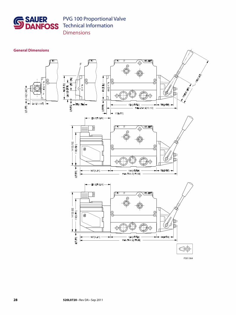
General Dimensions
29520L0720 • Rev DA • Sep 2011
PVG 100 Proportional ValveTechnical Information
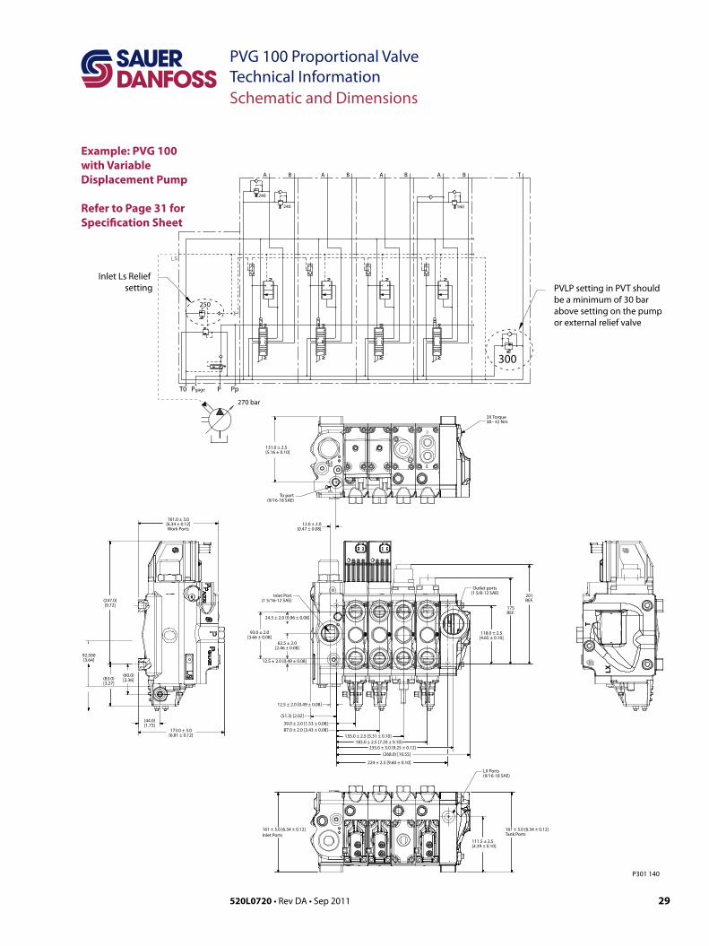
PVLP setting in PVT should be a minimum of 30 bar above setting on the pump or external relief valve
Inlet Ls Relief setting
P301 140
300
250
T0 P PpPgage
A B B B B TA A A
240
240
160
161 ± 3.0 [6.34 ± 0.12]Inlet Ports
161 ± 3.0 [6.34 ± 0.12]Tank Ports
111.5 ± 2.5[4.39 ± 0.10]
LX Ports(9/16-18 SAE)
LX
T
3X Torque38 - 42 Nm
131.0 ± 2.5[5.16 ± 0.10]
To port(9/16-18 SAE)
12.0 ± 2.0[0.47 ± 0.08]
161.0 ± 3.0[6.34 ± 0.12]Work Ports
173.0 ± 3.0[6.81 ± 0.12]
92.500[3.64]
(83.0)[3.27]
(44.0)[1.73]
(60.0)[2.36]
(247.0)[9.72]
12.5 ± 2.0 [0.49 ± 0.08]
12.5 ± 2.0 [0.49 ± 0.08]
39.0 ± 2.0 [1.53 ± 0.08]
224 ± 2.5 [9.60 ± 0.10]
235.0 ± 3.0 [9.25 ± 0.12](268.0) [10.55]
135.0 ± 2.5 [5.31 ± 0.10]183.0 ± 2.5 [7.20 ± 0.10]
201REF.
175REF.
Outlet ports(1 5/8-12 SAE)
118.0 ± 2.5[4.65 ± 0.10]
Inlet Port(1 5/16-12 SAE)
93.0 ± 2.0[3.66 ± 0.08]
62.5 ± 2.0[2.46 ± 0.08]
(51.3) [2.02]
24.5 ± 2.0 [0.96 ± 0.08]
87.0 ± 2.0 [3.43 ± 0.08]
270 bar
Schematic and Dimensions
Example: PVG 100 with Variable Displacement Pump
Refer to Page 31 for Specification Sheet
30 520L0720 • Rev DA • Sep 2011
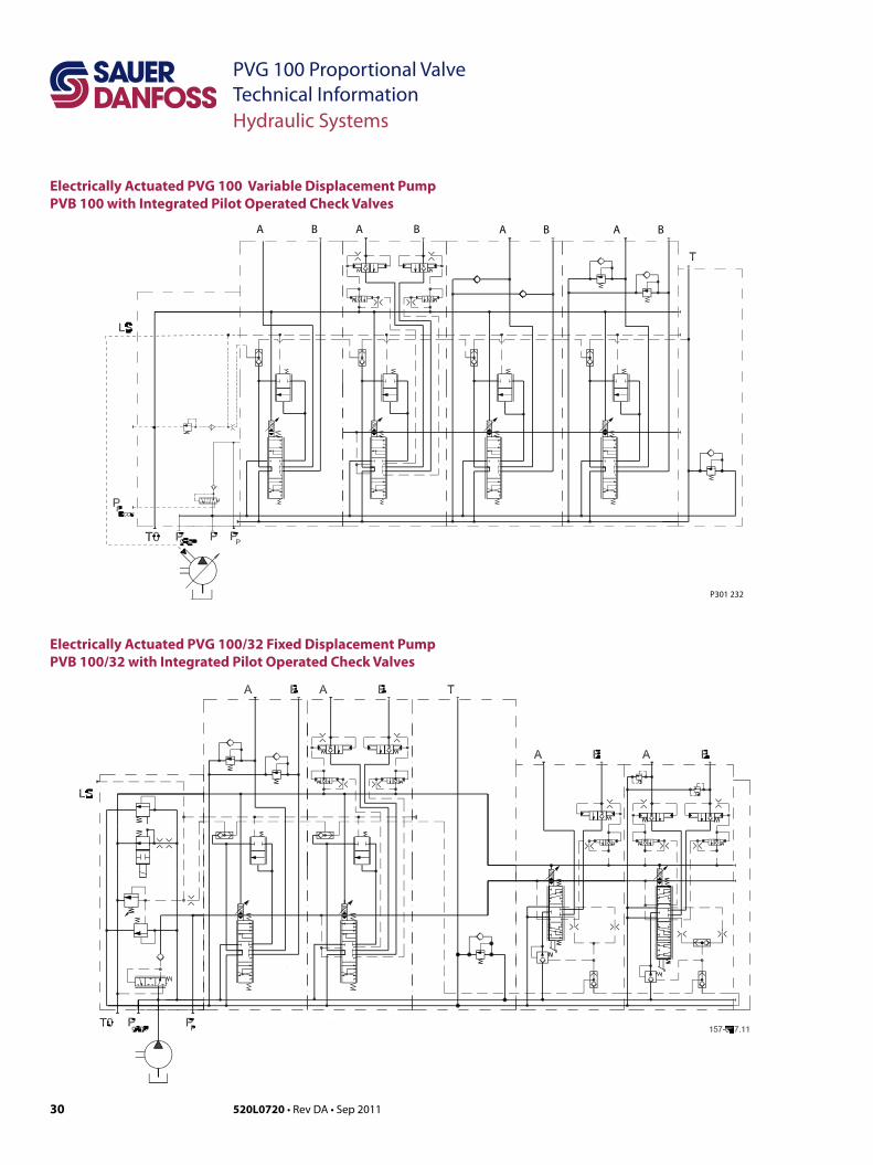
PVG 100 Proportional ValveTechnical InformationHydraulic Systems
Electrically Actuated PVG 100 Variable Displacement PumpPVB 100 with Integrated Pilot Operated Check Valves
P301 232
A AB B A AB B
Electrically Actuated PVG 100/32 Fixed Displacement PumpPVB 100/32 with Integrated Pilot Operated Check Valves
31520L0720 • Rev DA • Sep 2011
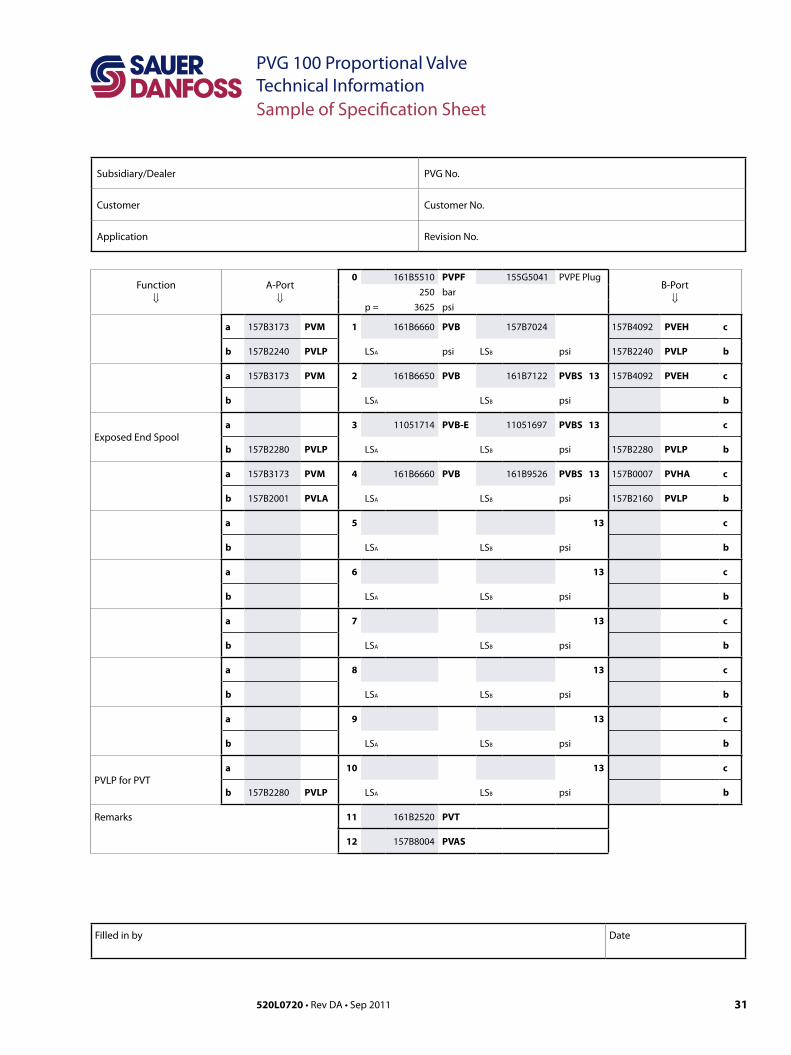
PVG 100 Proportional ValveTechnical InformationSample of Specification Sheet
Subsidiary/Dealer PVG No.
Customer Customer No.
Application Revision No.
Function⇓
A-Port⇓
0 161B5510 PVPF 155G5041 PVPE PlugB-Port⇓
250 bar
p = 3625 psi
a 157B3173 PVM 1 161B6660 PVB 157B7024 157B4092 PVEH c
b 157B2240 PVLP LSA psi LSB psi 157B2240 PVLP b
a 157B3173 PVM 2 161B6650 PVB 161B7122 PVBS 13 157B4092 PVEH c
b LSA LSB psi b
Exposed End Spoola 3 11051714 PVB-E 11051697 PVBS 13 c
b 157B2280 PVLP LSA LSB psi 157B2280 PVLP b
a 157B3173 PVM 4 161B6660 PVB 161B9526 PVBS 13 157B0007 PVHA c
b 157B2001 PVLA LSA LSB psi 157B2160 PVLP b
a 5 13 c
b LSA LSB psi b
a 6 13 c
b LSA LSB psi b
a 7 13 c
b LSA LSB psi b
a 8 13 c
b LSA LSB psi b
a 9 13 c
b LSA LSB psi b
PVLP for PVTa 10 13 c
b 157B2280 PVLP LSA LSB psi b
Remarks 11 161B2520 PVT
12 157B8004 PVAS
Filled in by Date
32 520L0720 • Rev DA • Sep 2011
PVG 100 Proportional ValveTechnical Information
Oil
Particle Content, Degree of Contamination
Other Operating Conditions
The main duty of the oil in a hydraulic system is to transfer energy; but it must also lubricate the moving parts in hydraulic components, protect them against corrosion, and transport dirt particles and heat out of the system. It is therefore important to choose the correct oil with the correct additives. This gives normal operation and long working life.
Mineral oilFor systems with PVG 100 valves Sauer-Danfoss recommends the use of mineral-based hydraulic oil containing additives: Type HLP (DIN 51524) or HM (ISO 6743/4).
Non-flammable fluidsPhosphate-esters (HFDR fluids) can be used without special precautions. However, dynamic seals must be replaced with FPM (Viton) seals. So please contact the Sauer-Danfoss Sales Organization if the PVG 100 valve is to be used with phosphate-esters.The following fluids should only be used according to agreement with the Sales Organization for Sauer-Danfoss:• Water-glycol mixtures (HFC fluids)• Water-oil emulsions (HFB fluids)• Oil-water emulsions (HFAE fluids)
Biodegradable oilsPVG 100 valves can be used in systems with rapeseed oil. The use of rapeseed oil is conditioned by- complying with the demands on viscosity, water content, temperature and filtering etc. (see chapters below and technical data page 7).- adapting the operating conditions to the directions of the oil supplier.
Before using other biodegradable fluids, please consult the Sauer-Danfoss Organization.
Oil filtration must prevent particle content from exceeding an acceptable level, i.e. an acceptable degree of contamination.
Maximum contamination for PVG 100 is 23/19/16 (see ISO 4406. Calibration in accordance with the ACFTD method).
In our experience a degree of contamination of 23/19/16 can be maintained by using a filter fineness as described in the next section.
33520L0720 • Rev DA • Sep 2011
PVG 100 Proportional ValveTechnical InformationOther Operating Conditions
Filtration Effective filtration is the most important precondition in ensuring that a hydraulic system performs reliably and has a long working life. Filter manufacturers issue instructions and recommendations. It is advisable to follow them.
System filtersWhere demands on safety and reliability are very high a pressure filter with bypass and indicator is recommended. Experience shows that a 10 µm nominal filter (or finer) or a 20 µm absolute filter (or finer) is suitable.It is our experience that a return filter is adequate in a purely mechanically operated valve system.
The fineness of a pressure filter must be selected as described by the filter manufacturer so that a particle level of 23/19/16 is not exceeded.
The filter must be fitted with pressure gauge or dirt indicator to make it possible to check the condition of the filter.
In systems with differential cylinders or accumulators the return filter must be sized to suit the max. return oil flow. Pressure filters must be fitted to suit max. pump oil flow.
Internal filtersThe filters built into PVG 100 are not intended to filter the system but to protect important components against large particles. Such particles can appear in the system as a result of pump damage, hose fracture, use of quick-couplings, filter damage, starting up, contamination, etc.
The filter in the electrical actuator PVE protecting the solenoid valves has a mesh of 150 µm.Bursting pressure drop for internal filters is 25 bar [360 psi].
34 520L0720 • Rev DA • Sep 2011
PVG 100 Proportional ValveTechnical Information
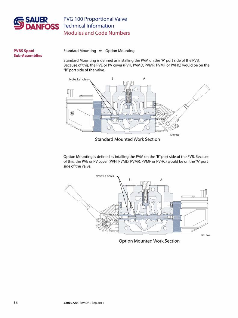
Standard Mounting - vs - Option Mounting
Standard Mounting is defined as installing the PVM on the “A” port side of the PVB. Because of this, the PVE or PV cover (PVH, PVMD, PVMR, PVMF or PVHC) would be on the “B” port side of the valve.
Modules and Code Numbers
PVBS Spool Sub-Assemblies
Option Mounting is defined as intalling the PVM on the “B” port side of the PVB. Because of this, the PVE or PV cover (PVH, PVMD, PVMR, PVMF or PVHC) would be on the “A” port side of the valve.
B A
Standard Mounted Work Section
Note: Ls holes
P301 065
B ANote: Ls holes
Option Mounted Work SectionP301 066
35520L0720 • Rev DA • Sep 2011
PVG 100 Proportional ValveTechnical Information
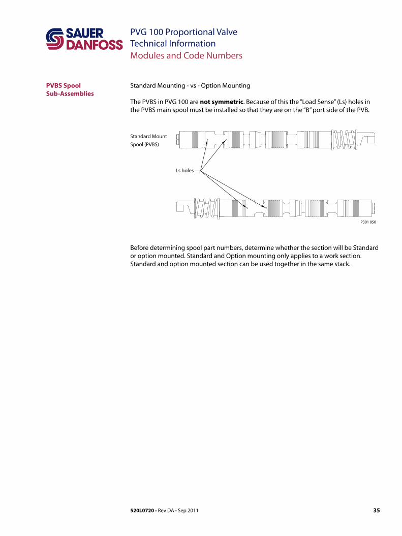
Standard Mounting - vs - Option Mounting
The PVBS in PVG 100 are not symmetric. Because of this the “Load Sense” (Ls) holes in the PVBS main spool must be installed so that they are on the “B” port side of the PVB.
Modules and Code Numbers
PVBS Spool Sub-Assemblies
Before determining spool part numbers, determine whether the section will be Standard or option mounted. Standard and Option mounting only applies to a work section. Standard and option mounted section can be used together in the same stack.
Ls holes
P301 050
Standard Mount
Spool (PVBS)
36 520L0720 • Rev DA • Sep 2011
PVG 100 Proportional ValveTechnical Information
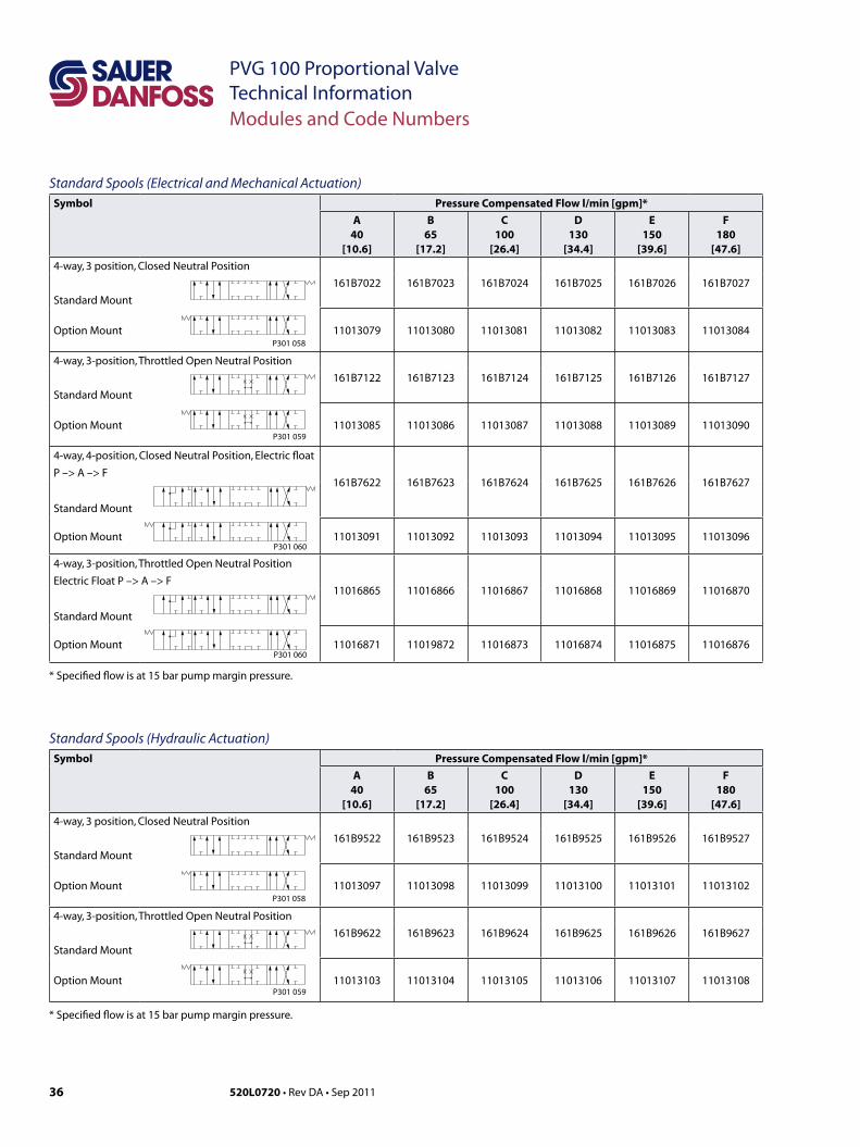
Standard Spools (Electrical and Mechanical Actuation)Symbol Pressure Compensated Flow l/min [gpm]*
A40
[10.6]
B65
[17.2]
C100
[26.4]
D130
[34.4]
E150
[39.6]
F180
[47.6]4-way, 3 position, Closed Neutral Position
161B7022 161B7023 161B7024 161B7025 161B7026 161B7027
Standard Mount
P301 058Option Mount 11013079 11013080 11013081 11013082 11013083 11013084
4-way, 3-position, Throttled Open Neutral Position
161B7122 161B7123 161B7124 161B7125 161B7126 161B7127
Standard Mount
P301 059Option Mount 11013085 11013086 11013087 11013088 11013089 11013090
4-way, 4-position, Closed Neutral Position, Electric float
P –> A –> F161B7622 161B7623 161B7624 161B7625 161B7626 161B7627
Standard Mount
P301 060Option Mount 11013091 11013092 11013093 11013094 11013095 11013096
4-way, 3-position, Throttled Open Neutral Position
Electric Float P –> A –> F11016865 11016866 11016867 11016868 11016869 11016870
Standard Mount
P301 060Option Mount 11016871 11019872 11016873 11016874 11016875 11016876
* Specified flow is at 15 bar pump margin pressure.
Standard Spools (Hydraulic Actuation)Symbol Pressure Compensated Flow l/min [gpm]*
A40
[10.6]
B65
[17.2]
C100
[26.4]
D130
[34.4]
E150
[39.6]
F180
[47.6]4-way, 3 position, Closed Neutral Position
161B9522 161B9523 161B9524 161B9525 161B9526 161B9527
Standard Mount
P301 058Option Mount 11013097 11013098 11013099 11013100 11013101 11013102
4-way, 3-position, Throttled Open Neutral Position
161B9622 161B9623 161B9624 161B9625 161B9626 161B9627
Standard Mount
P301 059Option Mount 11013103 11013104 11013105 11013106 11013107 11013108
* Specified flow is at 15 bar pump margin pressure.
Modules and Code Numbers
37520L0720 • Rev DA • Sep 2011
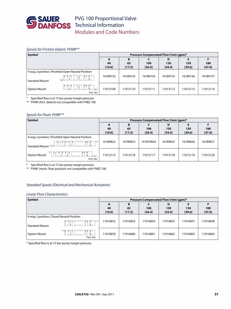
PVG 100 Proportional ValveTechnical InformationModules and Code Numbers
Spools for Friction Detent: PVMR**Symbol Pressure Compensated Flow l/min [gpm]*
A40
[10.6]
B65
[17.2]
C100
[26.4]
D130
[34.4]
E150
[39.6]
F180
[47.6]4-way, 3-position, Throttled Open Neutral Position
161B9732 161B9733 161B9734 161B9735 161B9736 161B9737
Standard Mount
P301 061Option Mount 11013109 11013110 11013111 11013112 11013113 11013114
* Specified flow is at 15 bar pump margin pressure.** PVMR (frict. detent) not compatible with PVBZ 100
Spools for Float: PVMF**Symbol Pressure Compensated Flow l/min [gpm]*
A40
[10.6]
B65
[17.2]
C100
[26.4]
D130
[34.4]
E150
[39.6]
F180
[47.6]4-way, 3 position, Throttled Open Neutral Position
161B9822 161B9823 161B79824 161B9825 161B9826 161B9827
Standard Mount
P301 062
Option Mount 11013115 11013116 11013117 11013118 11013119 11013120
* Specified flow is at 15 bar pump margin pressure.** PVMF (mech. float position) not compatible with PVBZ 100
Standard Spools (Electrical and Mechanical Actuation)
Linear Flow CharacteristicsSymbol Pressure Compensated Flow l/min [gpm]*
A40
[10.6]
B65
[17.2]
C100
[26.4]
D130
[34.4]
E150
[39.6]
F180
[47.6]4-way, 3 position, Closed Neutral Position
11016852 11016823 11016854 11016855 11016857 11016858
Standard Mount
P301 058Option Mount 11016859 11016860 11016861 11016862 11016863 11016864
* Specified flow is at 15 bar pump margin pressure.
38 520L0720 • Rev DA • Sep 2011
PVG 100 Proportional ValveTechnical Information
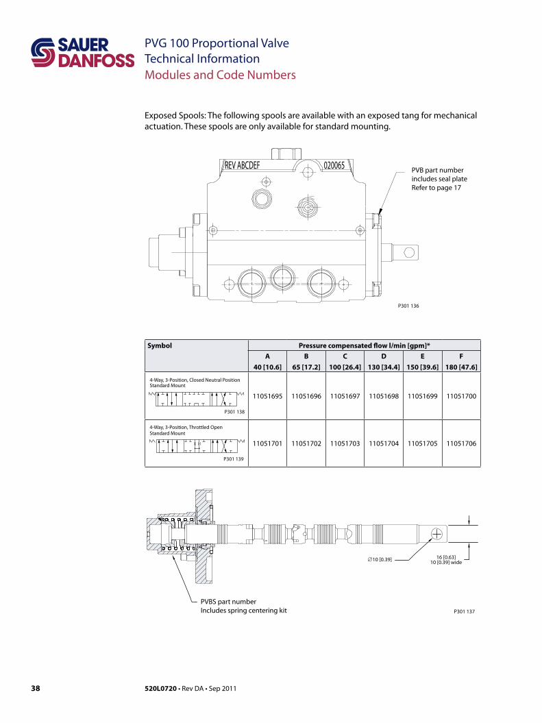
Exposed Spools: The following spools are available with an exposed tang for mechanical actuation. These spools are only available for standard mounting.
Symbol Pressure compensated flow l/min [gpm]*
A
40 [10.6]
B
65 [17.2]
C
100 [26.4]
D
130 [34.4]
E
150 [39.6]
F
180 [47.6]
4-Way, 3-Position, Closed Neutral PositionStandard Mount
P301 138
11051695 11051696 11051697 11051698 11051699 11051700
4-Way, 3-Position, Throttled OpenStandard Mount
P301 139
11051701 11051702 11051703 11051704 11051705 11051706
Modules and Code Numbers
PVB part number includes seal plateRefer to page 17
P301 136
REV ABCDEF 020065
PVBS part numberIncludes spring centering kit P301 137
∅10 [0.39] 16 [0.63]10 [0.39] wide
39520L0720 • Rev DA • Sep 2011
PVG 100 Proportional ValveTechnical InformationSafety in Application
Building in Safety All makes and all types of control valves (incl. proportional valves) can fail. Thus the necessary protection against the serious consequences of function failure should always be built into the system. For each application an assessment should be made for the consequences of pressure failure and uncontrolled or blocked movements.
To determine the degree of protection that is required to be built into the application, system tools such an FMEA (Failure Mode and Effect Analysis) and Hazard and Risk Analysis can be used.
FMEA (Failure Mode and Effect Analysis) IEC EN 61508FMEA is a tool used for analyzing potential risks. This analytical technique is utilized to define, identify, and prioritize the elimination or reduction of known and/or potential failures from a given system before it is released for production.Please refer to IEC FMEA Standard 61508.
Hazard and Risk Analysis ISO 12100-1 / 14121This analysis is a tool used in new applications as it will indicate whether there are special safety considerations to be meet according to the machine directives EN 13849. Dependent on the determined levels conformety this analysis will detirmine if any extra requirements for the product design, development process, production process or maintenance, i.e. the complete product life cycle.
WWarningAll makes/brands and types of directional control valves – inclusive proportional valves – can fail and cause serious damage. It is therefore important to analyze all aspects of the application. Because the proportional valves are used in many different operation conditions and applications, the manufacturer of the application is alone responsible for making the final selection of the products – and assuring that all performance, safety and warning requirements of the application are met. The process of choosing the control system – and safety levels – is governed by the machine directives EN 13849 (Safety related requirements for control systems).
40 520L0720 • Rev DA • Sep 2011
PVG 100 Proportional ValveTechnical Information
SupplyControl
NeutralDetection
Signal Conditioning
FailureDetection
FaultMonitoring
PVE fault output
SignalConditioning
SupplyMain controller
Hydraulic deactivation
HMI / Joystick
ControlSignal
Emergency stop andMan present switch Motion detection sensor
PVE
Main control valve
Main power supply(battery)
Joystick neutral switch
P301 317
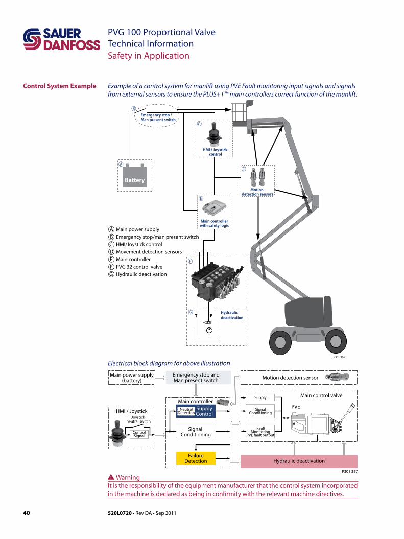
Control System Example
Safety in Application
Example of a control system for manlift using PVE Fault monitoring input signals and signals from external sensors to ensure the PLUS+1™ main controllers correct function of the manlift.
Electrical block diagram for above illustration
Emergency stop / Man present switch
T P
BatteryMotion
detection sensors
Main controller with safety logic
Hydraulic deactivation
HMI / Joystick control
A
B
C
D
E
F
G
P301 316
A Main power supplyB Emergency stop/man present switchC HMI/Joystick controlD Movement detection sensorsE Main controllerF PVG 32 control valveG Hydraulic deactivation
WWarningIt is the responsibility of the equipment manufacturer that the control system incorporated in the machine is declared as being in confirmity with the relevant machine directives.
41520L0720 • Rev DA • Sep 2011
PVG 100 Proportional ValveTechnical Information
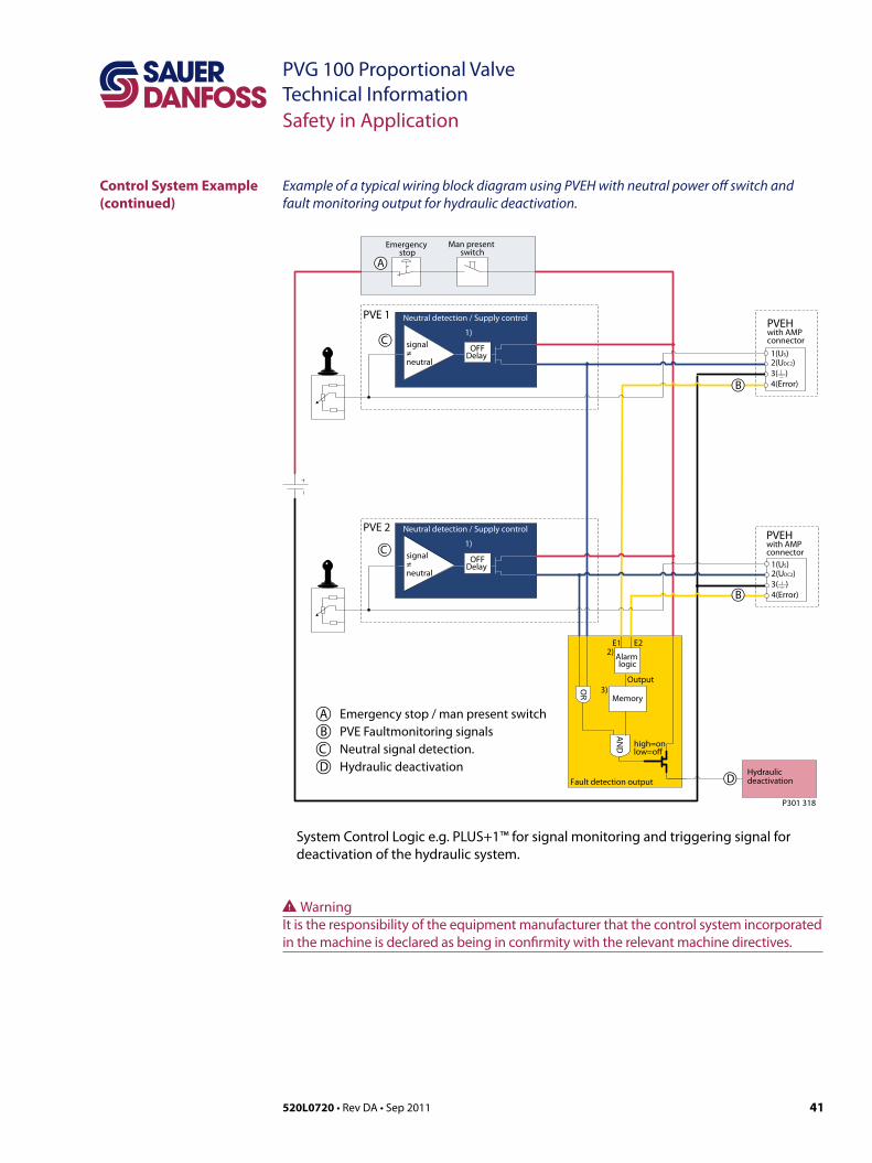
Example of a typical wiring block diagram using PVEH with neutral power off switch and fault monitoring output for hydraulic deactivation.
System Control Logic e.g. PLUS+1™ for signal monitoring and triggering signal for deactivation of the hydraulic system.
Fault detection output
high=onlow=o
Alarm logic
2)
Memory3)
E1 E2
Output
AN
D
OR
Neutral detection / Supply control
signal≠neutral
OFFDelay
1)
2(UDC2)3( )4(Error)
1(US)
PVEH with AMP connector
2(UDC2)3( )4(Error)
1(US)
PVEHwith AMP connector
Hydraulicdeactivation
Neutral detection / Supply control
signal≠neutral
OFFDelay
1)
PVE 1
PVE 2
Emergency stop
Man present switch
C
C
D
B
B
A
P301 318
Safety in Application
A Emergency stop / man present switchB PVE Faultmonitoring signalsC Neutral signal detection.D Hydraulic deactivation
Control System Example (continued)
WWarningIt is the responsibility of the equipment manufacturer that the control system incorporated in the machine is declared as being in confirmity with the relevant machine directives.
42 520L0720 • Rev DA • Sep 2011
PVG 100 Proportional ValveTechnical Information
Neutral detection / Supply control
signal≠neutral
OFFDelay
1)
Fault detection output
2(UDC2)3( )4(Error)
1(US)
2(DI-B)3( )
1(DI-A)
PVEH-DI AMP connector
4(UDC)
PVEH-DIAMP supply connector
2(UDC2)3( )4(Error)
1(US)
2(DI-B)3( )
1(DI-A)
PVEH-DI AMP connector
4(UDC)
PVEH-DIAMP supply connector
AN
D
Hydraulicdeactivation
high=onlow=o
Neutral detection / Supply control
signal≠neutral
OFFDelay
1)
PVE 1
PVE 2
Fault detection
DelayDILogic Memory
US
DI-ADI-B
2)4)3)
Output
Fault detection
DelayDILogic Memory
US
DI-ADI-B
2)4)3)
Output
OR
Emergency Stop
Man present switch
P301 319
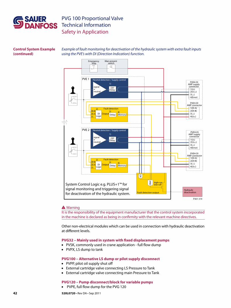
Example of fault monitoring for deactivation of the hydraulic system with extra fault inputs using the PVE’s with DI (Direction Indication) function.
System Control Logic e.g. PLUS+1™ for signal monitoring and triggering signal for deactivation of the hydraulic system.
Control System Example (continued)
Safety in Application
Other non-electrical modules which can be used in connection with hydraulic deactivation at different levels.
PVG32 – Mainly used in system with fixed displacement pumps• PVSK, commonly used in crane application - full flow dump• PVPX, LS dump to tank
PVG100 – Alternative LS dump or pilot supply disconnect• PVPP, pilot oil supply shut off• External cartridge valve connecting LS Pressure to Tank• External cartridge valve connecting main Pressure to Tank
PVG120 – Pump disconnect/block for variable pumps• PVPE, full flow dump for the PVG 120
WWarningIt is the responsibility of the equipment manufacturer that the control system incorporated in the machine is declared as being in confirmity with the relevant machine directives.
43520L0720 • Rev DA • Sep 2011
PVG 100 Proportional ValveTechnical InformationNotes
44 520L0720 • Rev DA • Sep 2011
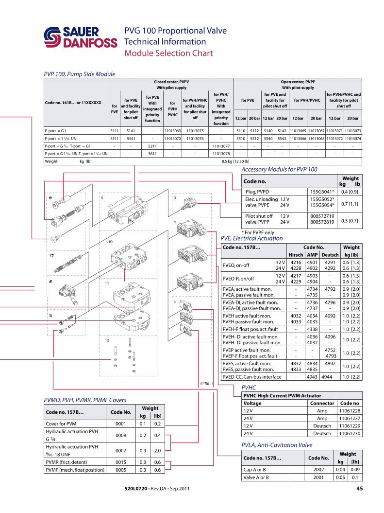
PVG 100 Proportional ValveTechnical InformationModule Selection Chart
PVM, mechanical actuation
Code no. 157B....With stop
screwWithout
stop screw
Standard
3171*
3161**3191 22.5°
3172 – 37.5°
Standard, with base, without
arm and button
3174 3194 37.5°
3175 3195 22.5°
Standard, without base, arm and
button3173 3193 –
Weight kg [lb] 0.4 [0.9]
* Anodized 157B3184
** Cast iron
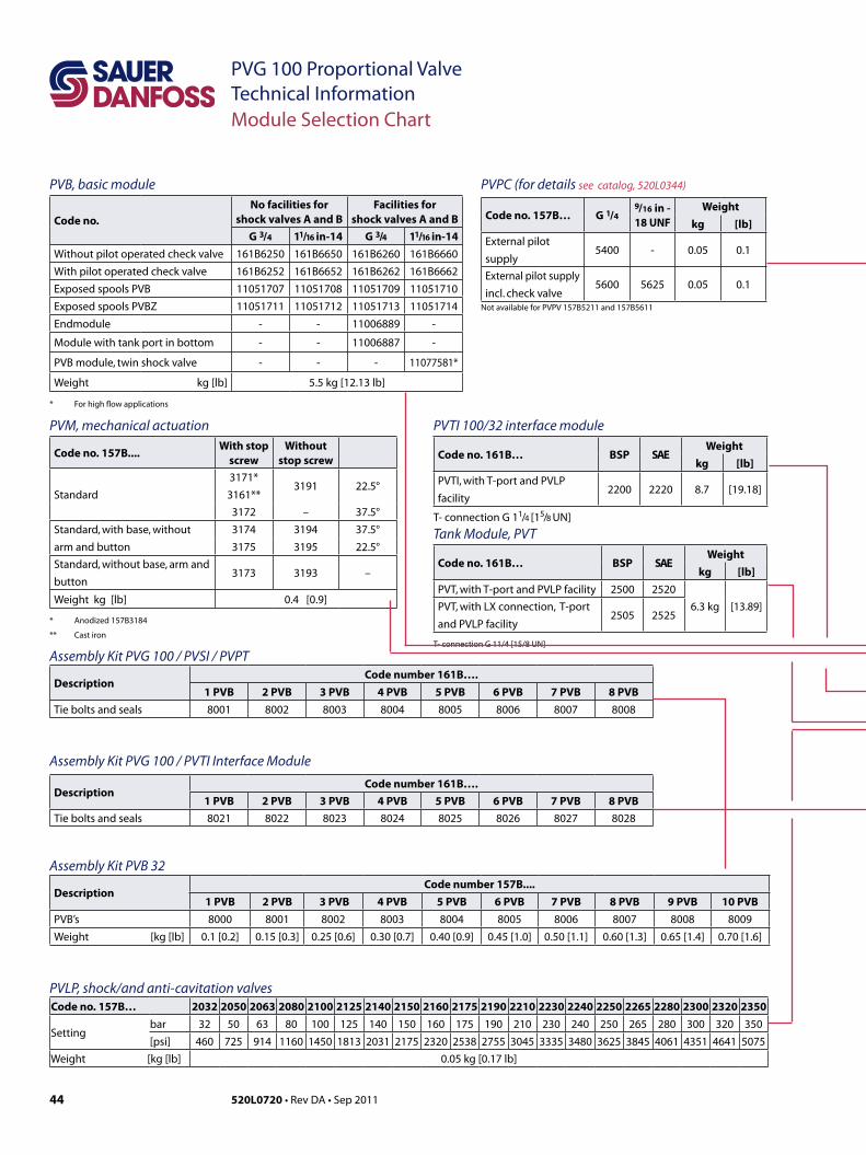
PVB, basic module
Code no.No facilities for
shock valves A and BFacilities for
shock valves A and BG 3/4 11/16 in-14 G 3/4 11/16 in-14
Without pilot operated check valve 161B6250 161B6650 161B6260 161B6660
With pilot operated check valve 161B6252 161B6652 161B6262 161B6662
Exposed spools PVB 11051707 11051708 11051709 11051710
Exposed spools PVBZ 11051711 11051712 11051713 11051714
Endmodule - - 11006889 -
Module with tank port in bottom - - 11006887 -
PVB module, twin shock valve - - - 11077581*
Weight kg [lb] 5.5 kg [12.13 lb]
* For high flow applications
Code no. 157B… 2032 2050 2063 2080 2100 2125 2140 2150 2160 2175 2190 2210 2230 2240 2250 2265 2280 2300 2320 2350
Settingbar 32 50 63 80 100 125 140 150 160 175 190 210 230 240 250 265 280 300 320 350
[psi] 460 725 914 1160 1450 1813 2031 2175 2320 2538 2755 3045 3335 3480 3625 3845 4061 4351 4641 5075
Weight [kg [lb] 0.05 kg [0.17 lb]
DescriptionCode number 157B....
1 PVB 2 PVB 3 PVB 4 PVB 5 PVB 6 PVB 7 PVB 8 PVB 9 PVB 10 PVBPVB’s 8000 8001 8002 8003 8004 8005 8006 8007 8008 8009
Weight [kg [lb] 0.1 [0.2] 0.15 [0.3] 0.25 [0.6] 0.30 [0.7] 0.40 [0.9] 0.45 [1.0] 0.50 [1.1] 0.60 [1.3] 0.65 [1.4] 0.70 [1.6]
PVPC (for details see catalog, 520L0344)
Code no. 157B… G 1/49/16 in -18 UNF
Weightkg [lb]
External pilot
supply5400 - 0.05 0.1
External pilot supply
incl. check valve5600 5625 0.05 0.1
Not available for PVPV 157B5211 and 157B5611
Assembly Kit PVB 32
PVLP, shock/and anti-cavitation valves
Tank Module, PVT
Code no. 161B… BSP SAEWeight
kg [lb]PVT, with T-port and PVLP facility 2500 2520
6.3 kg [13.89]PVT, with LX connection, T-port
and PVLP facility2505 2525
T- connection G 11/4 [15/8 UN]
PVTI 100/32 interface module
Code no. 161B… BSP SAEWeight
kg [lb]PVTI, with T-port and PVLP
facility2200 2220 8.7 [19.18]
T- connection G 11/4 [15/8 UN]
Assembly Kit PVG 100 / PVSI / PVPT
DescriptionCode number 161B….
1 PVB 2 PVB 3 PVB 4 PVB 5 PVB 6 PVB 7 PVB 8 PVBTie bolts and seals 8001 8002 8003 8004 8005 8006 8007 8008
Assembly Kit PVG 100 / PVTI Interface Module
DescriptionCode number 161B….
1 PVB 2 PVB 3 PVB 4 PVB 5 PVB 6 PVB 7 PVB 8 PVBTie bolts and seals 8021 8022 8023 8024 8025 8026 8027 8028
45520L0720 • Rev DA • Sep 2011
PVG 100 Proportional ValveTechnical Information
PVE, Electrical ActuationCode no. 157B… Code No. Weight
Hirsch AMP Deutsch kg [lb]
PVEO, on-off12 V24 V
42164228
49014902
42914292
0.6 [1.3]0.6 [1.3]
PVEO-R, on/off12 V24 V
42174229
49034904
--
0.6 [1.3]0.6 [1.3]
PVEA, active fault mon.PVEA, passive fault mon.
--
47344735
4792-
0.9 [2.0]0.9 [2.0]
PVEA-DI, active fault mon.PVEA-DI, passive fault mon.
--
47364737
4796-
0.9 [2.0]0.9 [2.0]
PVEH active fault mon.PVEH passive fault mon.
40324033
40344035
4092-
1.0 [2.2]1.0 [2.2]
PVEH-F float pos. act. fault - 4338 - 1.0 [2.2]
PVEH- DI active fault mon.PVEH- DI passive fault mon.
--
40364037
4096-
1.0 [2.2]
PVEP active fault mon.PVEP-F float pos. act. fault
--
--
47524793
1.0 [2.2]
PVES, active fault mon.PVES, passive fault mon.
48324833
48344835
4892-
1.0 [2.2]
PVED-CC, Can-bus interface - 4943 4944 1.0 [2.2]
Module Selection Chart
PVP 100, Pump Side Module
Code no. 157B… Code No.Weight
kg [lb]Cover for PVM 0001 0.1 0.2
Hydraulic actuation PVH
G 1/40008 0.2 0.4
Hydraulic actuation PVH9/16 -18 UNF
0007 0.9 2.0
PVMR (frict. detent) 0015 0.3 0.6
PVMF (mech. float position) 0005 0.3 0.6
PVMD, PVH, PVMR, PVMF Covers
PVLA, Anti-Cavitation Valve
Code no. 157B… Code No.Weight
kg [lb]Cap A or B 2002 0.04 0.09
Valve A or B 2001 0.05 0.1
Accessory Moduls for PVP 100
Code no. Weightkg lb
Plug, PVPD 155G5041* 0.4 [0.9]
Elec. unloading 12 Vvalve, PVPE 24 V
155G5052*155G5054* 0.7 [1.1]
Pilot shut off 12 Vvalve, PVPP 24 V
800572719800572819 0.3 [0.7]
* For PVPF only
PVHCPVHC High Current PWM ActuatorVoltage Connector Code no12 V Amp 1106122824 V Amp 1106122712 V Deutsch 1106122924 V Deutsch 11061230
Code no. 161B… or 11XXXXXX
Closed center, PVPVWith pilot supply
Open center, PVPFWith pilot supply
for PVE
for PVEand facility
for pilot shut off
for PVEWith
integratedpriorityfunction
for PVH/PVHC
for PVH/PVHC and facility
for pilot shut off
for PVH/PVHC With
integrated priority function
for PVEfor PVE and facility for
pilot shut offfor PVH/PVHC
for PVH/PVHC and facility for pilot
shut off
12 bar 20 bar 12 bar 20 bar 12 bar 20 bar 12 bar 20 bar
P-port = G 1 5111 5141 - 11013069 11013075 - 5110 5112 5140 5142 11013065 11013067 11013071 11013073
P-port = 1 5/16 UN 5511 5541 - 11013070 11013076 - 5510 5512 5540 5542 11013066 11013068 11013072 11013074
P-port = G 3/4. T-port = G1 - - 5211 - - 11013077 - - - - - - - -
P-port = G 11/16 UN. T -port = 15/16 UN - - 5611 - - 11013078 - - - - - - - -
Weight kg [lb] 8.5 kg [12.30 lb]
46 520L0720 • Rev DA • Sep 2011
PVG 100 Proportional ValveTechnical Information
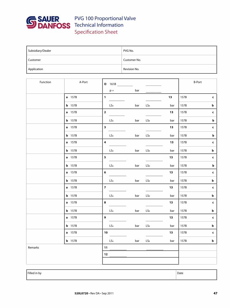
Order specification An order form for Saue-Danfoss PVG 100 hydraulic valve is shown on the next page. The form can be obtained from the Sauer-Danfoss Sales Organization.
Both the module selection chart on the previous pages and the order form are divided into fields 0, 1-10, 11, 12, 13, a, b, and c.
Each module has its own field:0: Pump side module PVP Plug for external pilot oil supply PVPC Electrical unloading valve PVPE Electrical pilot shut off valve PVPE1-10: Basic valves PVB13: Main spool PVBS a: Mechanical actuator PVM c: Cover for mechanical actuation PVMD Cover for hydraulic actuation PVH Electrical actuators PVE b: Shock and suction valve PVLP Suction valve PVLA 11: End plate PVSI Tank module PVT Interface module PVTI 12: Assembly kit PVAS
Please state- Code numbers of all modules required- Required setting (P) for pump side module
Standard and option assemblyThe PVG 100 valve group is assembled the way the module selection chart shows if the code number for PVM is written in field a, and the code number for PVMD, PVE or PVH in field c.The valve group is assembled so that the mechanical actuator is mounted on the opposite end of the basic module, if the code number for PVM is written in field c of the order form and the code numbers for PVMD, PVE or PVH in field a.
ReorderingThe space at the top right-hand corner of the form is for Sauer-Danfoss to fill in. The code number for the whole of the specified valve group (PVG No.) is entered here. In the event of a repeat order all you have to do is enter the number Sauer-Danfoss has given on the initial confirmation of order.
Order Specification
47520L0720 • Rev DA • Sep 2011
PVG 100 Proportional ValveTechnical InformationSpecification Sheet
Subsidiary/Dealer PVG No.
Customer Customer No.
Application Revision No.
Function A-PortO 161B
__________
__________
p = bar __________
B-Port
a 157B
b 157B
1 __________ __________
13 LSA bar LSB bar
157B c
157B b
a 157B
b 157B
2 __________
__________
13 LSA bar LSB bar
157B c
157B b
a 157B
b 157B
3 ___________ __________
13 LSA bar LSB bar
157B c
157B b
a 157B
b 157B
4 ___________ ___________
13 LSA bar LSB bar
157B c
157B b
a 157B
b 157B
5 ___________ ___________
13 LSA bar LSB bar
157B c
157B b
a 157B
b 157B
6 ___________ ___________
13 LSA bar LSB bar
157B c
157B b
a 157B
b 157B
7 ___________ ___________
13 LSA bar LSB bar
157B c
157B b
a 157B
b 157B
8 ___________ ___________
13 LSA bar LSB bar
157B c
157B b
a 157B
b 157B
9 ___________ ___________
13 LSA bar LSB bar
157B c
157B b
a 157B
b 157B
10 ___________ ___________
13 LSA bar LSB bar
157B c
157B b
Remarks 11 ___________ ___________
12 ___________
Filled in by Date
Local address:
Sauer-Danfoss GmbH & Co. OHGPostfach 2460, D-24531 NeumünsterKrokamp 35, D-24539 Neumünster, GermanyPhone: +49 4321 871 0Fax: +49 4321 871 122
Sauer-Danfoss ApSDK-6430 Nordborg, DenmarkPhone: +45 7488 4444Fax: +45 7488 4400
Sauer-Danfoss is a global manufacturer and supplier of high-quality hydraulic and electronic components. We specialize in providing state-of-the-art technology and solutions that excel in the harsh operating conditions of the mobile o -highway market. Building on our extensive applications expertise, we work closely with our customers to ensure exceptional performance for a broad range of o -highway vehicles.
We help OEMs around the world speed up system development, reduce costs and bring vehicles to market faster. Sauer-Danfoss – Your Strongest Partner in Mobile Hydraulics.
Go to www.sauer-danfoss.com for further product information.
Wherever o -highway vehicles are at work, so is Sauer-Danfoss.
We o er expert worldwide support for our customers, ensuring the best possible solutions for outstanding performance. And with an extensive network of Global Service Partners, we also provide comprehensive global service for all of our components.
Please contact the Sauer-Danfoss representative nearest you.
Products we o er:
• Bent Axis Motors
• Closed Circuit Axial Piston Pumps and Motors
• Displays
• Electrohydraulic Power Steering
• Electrohydraulics
• Hydraulic Power Steering
• Integrated Systems
• Joysticks and Control Handles
• Microcontrollers and Software
• Open Circuit Axial Piston Pumps
• Orbital Motors
• PLUS+1™ GUIDE
• Proportional Valves
• Sensors
• Steering
• Transit Mixer Drives
Members of the Sauer-Danfoss Group:
Comatrolwww.comatrol.com
Schwarzmüller-Inverterwww.schwarzmueller-inverter.com
Turolla www.turollaocg.com
Hydro-Gear www.hydro-gear.com
Sauer-Danfoss-Daikinwww.sauer-danfoss-daikin.com
Sauer-Danfoss (US) Company2800 East 13th StreetAmes, IA 50010, USAPhone: +1 515 239 6000Fax: +1 515 239 6618
Sauer-Danfoss-Daikin LTD.Shin-Osaka TERASAKI 3rd Bldg. 6F1-5-28 Nishimiyahara, Yodogawa-kuOsaka 532-0004, JapanPhone: +81 6 6395 6066Fax: +81 6 6395 8585
w w w . s a u e r - d a n f o s s . c o m520L0720 • Rev DA • Sep 2011