Embed Size (px)
Citation preview
MAKING MODERN LIVING POSSIBLE
Service Manual
PVG 100 Proportional Valves
powersolutions.danfoss.com
Revision history Table of revisions
Date Changed Rev
October 2014 Danfoss layout BA
June 2009 First edition AA
Service Manual PVG 100 Proportional Valves
2 11048807 • Rev BA • October 2014

IntroductionOverview..............................................................................................................................................................................................5General Instructions........................................................................................................................................................................ 5
Remove the unit.......................................................................................................................................................................... 5Keep it clean..................................................................................................................................................................................5Replace all O-rings and gaskets............................................................................................................................................. 5Secure the unit............................................................................................................................................................................. 5
Safety Precautions............................................................................................................................................................................6Unintended machine movement..........................................................................................................................................6Flammable cleaning solvents................................................................................................................................................. 6Fluid under pressure.................................................................................................................................................................. 6Personal safety............................................................................................................................................................................. 6Hazardous material.................................................................................................................................................................... 6
Acronyms ............................................................................................................................................................................................7
OperationPVG 100 Group with Open Center PVPF.................................................................................................................................. 8PVG 100 Group with Closed Center PVPV............................................................................................................................... 8PVG 100 Sectional Drawing.......................................................................................................................................................... 9PVPC Plug for External Pilot Oil Supply..................................................................................................................................10
PVPC with Check Valve for Open Center PVP.................................................................................................................10PVPC without Check Valve for Open Center PVP..........................................................................................................10
Friction detent.................................................................................................................................................................................11PVMR Friction Detent..............................................................................................................................................................11PVMF Mechanical Float Position Lock...............................................................................................................................11
PVBS, Main Spools for Flow Control (standard) ................................................................................................................. 12PVBS, Main Spools for Flow Control (with linear characteristics) ................................................................................ 12PVPP Electrical Pilot Shut-Off Valve.........................................................................................................................................12PVPE Electrical Full Flow Unloading Valve............................................................................................................................13
System TroubleshootingOverview........................................................................................................................................................................................... 14Troubleshooting a PVG Valve.................................................................................................................................................... 14No Cylinder/Motor Response in Either Direction when Remote Controller is Actuated..................................... 16Cylinder/Motor Responds in One Direction Only...............................................................................................................16Main Valve Spool Moves without Oil Passing to Cylinder/Motor.................................................................................17Cylinder/Motor Operates without Remote Controller being Operated.................................................................... 17Cylinder/Motor Responds Slowly to Remote Electrical or Hydraulic Controller.....................................................18Erratic Cylinder/Motor Response to Electrical or Hydraulic Controller Operation.................................................18Hydraulic Oil Supply......................................................................................................................................................................18Electrical Supply............................................................................................................................................................................. 19Hydraulic (remote) Pilot Control Pressure............................................................................................................................ 20
PVG 100 Component TroubleshootingOpen Center Pressure Relief Valve...........................................................................................................................................21Closed Center Pressure Relief Valve........................................................................................................................................ 21Pressure Reducing Pilot Valve................................................................................................................................................... 21Pressure Gauge Connection.......................................................................................................................................................23Pressure Matching Spool.............................................................................................................................................................24LS Connection................................................................................................................................................................................. 24LS Signal............................................................................................................................................................................................ 25Shuttle Valve....................................................................................................................................................................................26Main Spool........................................................................................................................................................................................27Shock and Anti-Cavitation Valve PVLP...................................................................................................................................29Pressure Compensator.................................................................................................................................................................30Maximum Oil Flow Adjustment Screws for Ports A and B...............................................................................................31PVM Module.....................................................................................................................................................................................32PVT/PVTI Module............................................................................................................................................................................33PVAS Module................................................................................................................................................................................... 34PVPP Pilot Shut Off Valve............................................................................................................................................................ 35PVPE Unloading Valve ................................................................................................................................................................. 35
Service Manual PVG 100 Proportional Valves
Contents
11048807 • Rev BA • October 2014 3
PVB Pilot Check Valve .................................................................................................................................................................. 35PVEH, PVES, Electrical Actuators...............................................................................................................................................36
Troubleshooting Considerations........................................................................................................................................ 36PVEO On/Off Electrical Actuator...............................................................................................................................................37
PVPC Plug for External Pilot Control..................................................................................................................................38PVMR Friction Module............................................................................................................................................................ 39
Service Manual PVG 100 Proportional Valves
Contents
4 11048807 • Rev BA • October 2014

Overview
This manual includes information for servicing PVG 100 valves. It includes a description of the units andtheir individual components, troubleshooting information, and minor repair procedures.
Performing minor repairs may require removal from the vehicle/machine. Thoroughly clean the unitbefore beginning maintenance, or repair activities. Since dirt and contamination are the greatest enemiesof any type of hydraulic equipment, follow cleanliness requirements strictly. This is especially importantwhen changing the system filter and when removing hoses or plumbing.
A worldwide network of Danfoss Global Service Partners is available for major repairs. Danfoss GlobalService Partners are trained by the factory and certified on a regular basis. You can locate your nearestGlobal Service Partner using the distributor locator at www.Danfoss.com. Click on the Sales and Servicelink.
For specifications and operating parameters on PVG 100 valves, refer to PVG 100 Technical InformationManual 520L0720.
C Caution
Do not attempt to service PVG valves without build sheet specifications for reference.
General Instructions
Follow these general procedures when repairing PVG 100 valves.
Remove the unit
Chock the wheels on the vehicle or lock the mechanism to inhibit movement. Prior to performing repairs,remove the unit from the vehicle/machine. Be aware that hydraulic fluid may be under high pressureand/or hot. Inspect the outside of the motor and fittings for damage. Cap hoses after removal to preventcontamination.
Keep it clean
Cleanliness is a primary means of assuring satisfactory motor life, on either new or repaired units. Cleanthe outside of the motor thoroughly before disassembly. Take care to avoid contamination of the systemports. Cleaning parts by using a clean solvent wash and air drying is usually adequate.
As with any precision equipment, all parts must be kept free of foreign materials and chemicals. Protectall exposed sealing surfaces and open cavities from damage and foreign material. If left unattended,cover the motor with a protective layer of plastic.
Replace all O-rings and gaskets
It is recommended that all O-rings be replaced. Lightly lubricate all O-rings with clean petroleum jellyprior to assembly.
Secure the unit
Service Manual PVG 100 Proportional Valves
Introduction
11048807 • Rev BA • October 2014 5
For repair, place the unit in a stable position with the shaft pointing downward. Secure the motor whileremoving and torquing controls, and valves.Always consider safety precautions before beginning aservice procedure. Protect yourself and others from injury. Take the following general precautionswhenever servicing a hydraulic system.
Safety Precautions
Always consider safety precautions before beginning a service procedure. Protect yourself and othersfrom injury. Take the following general precautions whenever servicing a hydraulic system.
Unintended machine movement
W Warning
Unintended movement of the machine or mechanism may cause injury to the technician or bystanders.To protect against unintended movement, secure the machine or disable/disconnect the mechanismwhile servicing.
Flammable cleaning solvents
W Warning
Some cleaning solvents are flammable. To avoid possible fire, do not use cleaning solvents in an areawhere a source of ignition may be present.
Fluid under pressure
W Warning
Escaping hydraulic fluid under pressure can have sufficient force to penetrate your skin causing seriousinjury and/or infection. This fluid may also be hot enough to cause burns. Use caution when dealing withhydraulic fluid under pressure. Relieve pressure in the system before removing hoses, fittings, gauges, orcomponents. Never use your hand or any other body part to check for leaks in a pressurized line. Seekmedical attention immediately if you are cut by hydraulic fluid.
Personal safety
W Warning
Protect yourself from injury. Use proper safety equipment, including safety glasses, at all times.
Hazardous material
W Warning
Hydraulic fluid contains hazardous material. Avoid prolonged contact with hydraulic fluid. Alwaysdispose of used hydraulic fluid according to state, and federal environmental regulations.
Service Manual PVG 100 Proportional Valves
Introduction
6 11048807 • Rev BA • October 2014
Acronyms
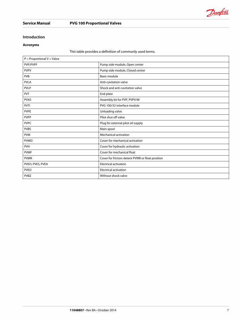
This table provides a definition of commonly used terms.
P = Proportional V = Valve
PVP/PVPF Pump side module, Open center
PVPV Pump side module, Closed center
PVB Basic module
PVLA Anti-cavitation valve
PVLP Shock and anti-cavitation valve
PVT End plate
PVAS Assembly kit for PVP, PVPV/M
PVTI PVG 100/32 interface module
PVPE Unloading valve
PVPP Pilot shut off valve
PVPC Plug for external pilot oil supply
PVBS Main spool
PVM Mechanical activation
PVMD Cover for mechanical activation
PVH Cover for hydraulic activation
PVMF Cover for mechanical float
PVMR Cover for friction detent PVMR or float position
PVEH, PVES, PVEA Electrical activation
PVEO Electrical activation
PVBZ Without shock valve
Service Manual PVG 100 Proportional Valves
Introduction
11048807 • Rev BA • October 2014 7

PVG 100 Group with Open Center PVPF
When the pump is started and the main spools in the individual basic modules are in the neutral position,oil flows from the pump, through connection P, across the pressure matching spool to tank. The oil flowled across the pressure matching spool determines the pump pressure (stand-by pressure).
When one or more of the main spools are actuated, the highest load pressure is fed through the shuttlevalve circuit to the spring chamber behind the pressure matching spool, and completely or partiallycloses the connection to tank.
Pump pressure is applied to the opposite side of the pressure matching spool. The pressure relief valvewill open should the load pressure exceed the set value, diverting pump flow back to tank.
In a pressure-compensated basic module the compensator maintains a constant pressure drop across themain spool – both when the load changes and when a module with a higher load pressure is actuated.
Besides independent flow the other advantage of post-compensated work sections is the ability tocontrol multifunction operation when flow demand exceeds pump capacity. This means that all worksections will continue to function regardless of differences in their load and regardless of the pump flow.The flow relationships specified between functions will be maintained over the full flow range of thepump.
The shock valves PVLP with fixed setting and the suction valves PVLA on ports A and B are used for theprotection of the individual working function against overload and/or cavitation.
PVG 100 Group with Closed Center PVPV
In load sensing systems, the load pressure is led to the pump regulator via the LS connection. In theneutral position, the pump control sets the displacement so that leakage in the system is compensatedfor, to maintain the set stand-by pressure.
When a main spool is actuated, the pump regulator will adjust the displacement so that the setdifferential pressure between P and LS is maintained. The load sense relief valve in PVP should be set at apressure of approximately 30 bar [435 psi] below the maximum system pressure (set on the pump orexternal pressure relief valve).
With post-compensated valves, the rating of the A and B work-port flow will depend on the pressuredrop across the main spool PVBS. In open center systems, this pressure drop (standby-pressure) isgenerated by the volume of pump flow led to tank across the pressure adjusting spool in the inlet PVPF.Since the pressure drop varies with pump flow volume led to tank, also the A and B work-port flow willvary.In closed center systems, the pressure drop across the main spool equals the standby setting of thepump, measured at the P port of the valve. The A and B work port flow will remain unchanged as long asthe standby is unchanged.
Service Manual PVG 100 Proportional Valves
Operation
8 11048807 • Rev BA • October 2014

PVG 100 Sectional Drawing
1. LS relief valve 2. LS connection 3. Priority spool for CF 4. LS connection for steering unit 5. Shuttle valve 6. Pilot operated check valve, POC 7. LS line
8. Logic cartridge for POC 9. Pressure compensator 10. Shock and suction valve, PVLP 11. Main spool, PVBS 12. Max. oil flow adjustment screws for ports A and B 13. LS comp (LS signal sent back to compensators)
Service Manual PVG 100 Proportional Valves
Operation
11048807 • Rev BA • October 2014 9
PVPC Plug for External Pilot Oil Supply
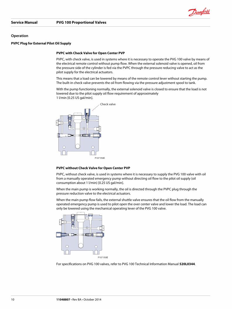
PVPC with Check Valve for Open Center PVP
PVPC, with check valve, is used in systems where it is necessary to operate the PVG 100 valve by means ofthe electrical remote control without pump flow. When the external solenoid valve is opened, oil fromthe pressure side of the cylinder is fed via the PVPC through the pressure reducing valve to act as thepilot supply for the electrical actuators.
This means that a load can be lowered by means of the remote control lever without starting the pump.The built-in check valve prevents the oil from flowing via the pressure adjustment spool to tank.
With the pump functioning normally, the external solenoid valve is closed to ensure that the load is notlowered due to the pilot supply oil flow requirement of approximately 1 l/min [0.25 US gal/min].
P107 958E
Check valve
PVPC without Check Valve for Open Center PVP
PVPC, without check valve, is used in systems where it is necessary to supply the PVG 100 valve with oilfrom a manually operated emergency pump without directing oil flow to the pilot oil supply (oilconsumption about 1 l/min) [0.25 US gal/min].
When the main pump is working normally, the oil is directed through the PVPC plug through thepressure reduction valve to the electrical actuators.
When the main pump flow fails, the external shuttle valve ensures that the oil flow from the manuallyoperated emergency pump is used to pilot open the over center valve and lower the load. The load canonly be lowered using the mechanical operating lever of the PVG 100 valve.
P107 958E
For specifications on PVG 100 valves, refer to PVG 100 Technical Information Manual 520L0344.
Service Manual PVG 100 Proportional Valves
Operation
10 11048807 • Rev BA • October 2014
Friction detent
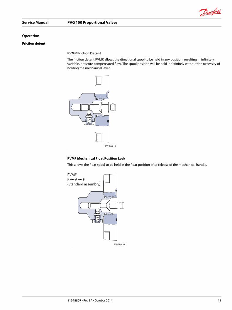
PVMR Friction Detent
The friction detent PVMR allows the directional spool to be held in any position, resulting in infinitelyvariable, pressure compensated flow. The spool position will be held indefinitely without the necessity ofholding the mechanical lever.
PVMF Mechanical Float Position Lock
This allows the float spool to be held in the float position after release of the mechanical handle.
PVMFP A F(Standard assembly)
Service Manual PVG 100 Proportional Valves
Operation
11048807 • Rev BA • October 2014 11

PVMFP A F(Optional assembly)
PVBS, Main Spools for Flow Control (standard)
When using standard flow control spools, the pump pressure is determined by the highest load pressure.This is done either via the pressure adjustment spool in open center PVP (fixed displacement pumps) orvia the pump regulator (variable displacement pumps).
In this way the pump pressure will always correspond to the load pressure plus the stand-by pressure ofthe pressure adjustment spool or the pump regulator.
This will normally give optimum and stable adjustment of the oil flow.
PVBS, Main Spools for Flow Control (with linear characteristics)
PVBS main spools with linear characteristic have a completely proportional ratio between control signaland oil flow in the range beyond the dead band.
PVPP Electrical Pilot Shut-Off Valve
The PVPP is an electrical pilot shut off valve. When de-energized, the valve connects the pilot supply tothe TØ gallery. In the event of a loss of electrical power, the valve is spring-biased with a connection toTØ.
The coil on the valve must be energized for pilot oil to be available in the valve stack.
This safety feature vents all hydraulic controls dependant on the PVG 100 pilot supply to the TØ gallery,thus reducing the possibility of accidental activation of a hydraulic work function.
Service Manual PVG 100 Proportional Valves
Operation
12 11048807 • Rev BA • October 2014
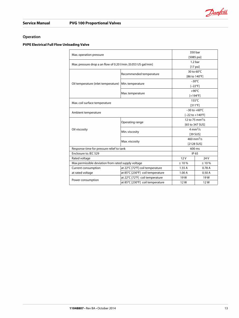
PVPE Electrical Full Flow Unloading Valve
Max. operation pressure 350 bar
[5085 psi]
Max. pressure drop a an flow of 0.20 l/min. [0.053 US gal/min] 1.2 bar
[17 psi]
Recommended temperature
30 to 60°C
[86 to 140°F]
Oil temperature (inlet temperature) Min. temperature –30°C
[–22°F]
Max. temperature
+90°C
[+194°F]
Max. coil surface temperature 155°C
[311°F]
Ambient temperature –30 to +60°C
[–22 to +140°F]
Operating range
12 to 75 mm2/s
[65 to 347 SUS]
Oil viscosity Min. viscosity
4 mm2/s
[39 SUS]
Max. viscosity
460 mm2/s
[2128 SUS]
Response time for pressure relief to tank 600 ms
Enclosure to. IEC 529 IP 65
Rated voltage 12 V 24 V
Max.permissible deviation from rated supply voltage ± 10 % ± 10 %
Current consumption at 22°C [72°F] coil temperature 1.55 A 0.78 A
at rated voltage at 85°C [230°F] coil temperature 1.00 A 0.50 A
Power consumption at 22°C [72°F] coil temperature 19 W 19 W
at 85°C [230°F] coil temperature 12 W 12 W
Service Manual PVG 100 Proportional Valves
Operation
11048807 • Rev BA • October 2014 13
Overview
This section provides general steps to follow if undesirable system conditions are observed. Follow thesteps listed until the problem is solved. Some of the items will be system specific. Always observe thesafety precautions listed in the Introduction section and related to your specific equipment.
Confirm that valve is built properly according to the specification sheet.
If necessary, install a lever to the valve to verify proper mechanical function.
Refer to PVG 100 Technical Information Manual 520L0720 for valve configuration information.
Refer to PVG 100 Parts Manual 520L0888 for part numbers.
W Warning
This troubleshooting guide for the PVG valve assemblies does not cover valves that have been alteredfrom original valve build specifications
Troubleshooting a PVG Valve
THINK - before troubleshooting a problem.
Every fault location process should follow a logical and systematic order.
It is wisest to start at the beginning:• Is the oil level correct when the pump is operating?
• Is the condition of oil and filters acceptable?
• Are pressure, flow, and flow direction as specified?
• Is the oil temperature too high or too low (oil viscosity)?
• Are there any unusual vibrations or noise (cavitation)?
If the driver of the vehicle is available, ask him:• What type of fault it is and how it affects the system?
• How long he has felt that something has been wrong?
• If he has “fiddled” with the components?
• If he has any hydraulic and electrical diagrams available?
Diagrams are often found in the instructions included with vehicles/machines.
Unfortunately they are often so technical that they are not of much use in a fault location situation.However; the diagram usually shows the order of, and the connections between, the individualcomponents.
When a defective component is identified, clean the component and its surroundings before removal.
Remove loose paint from pipes and fittings.
Cover all holes, hoses and pipe ends with plugs or seal with, for example, plastic bags after removal toavoid the entry of dirt during repairs.
Never disassemble hydraulic components outside.
Perform repairs in a workshop on a clean workbench (covered with clean cloth or newspaper).
Make sure that a Danfoss service manual for with the product is handy.
Follow the instructions word for word during disassembly and assembly.
If these instructions are not followed closely the system may not operate correctly after repairs arecompleted.
Note that in some cases special tools are necessary for assembling the product.
Service Manual PVG 100 Proportional Valves
System Troubleshooting
14 11048807 • Rev BA • October 2014

Our service manuals give full guidance on use of special tools.
Troubleshooting flow chart
Problem?
MechanicalMechanicalNoNo
HydraulicHydraulicNoNo
ElectricalElectricalNoNo
ElectronicElectronicNoNo
Software
Problem?Problem?
MechanicalMechanicalNoNo
MechanicalMechanicalNoNo
HydraulicHydraulicNoNo
HydraulicHydraulicHydraulicHydraulicNoNo
ElectricalElectricalNoNo
ElectricalElectricalElectricalElectricalNoNo
ElectronicElectronicNoNo
ElectronicElectronicElectronicElectronicNoNo
SoftwareSoftware
P107 823
Service Manual PVG 100 Proportional Valves
System Troubleshooting
11048807 • Rev BA • October 2014 15
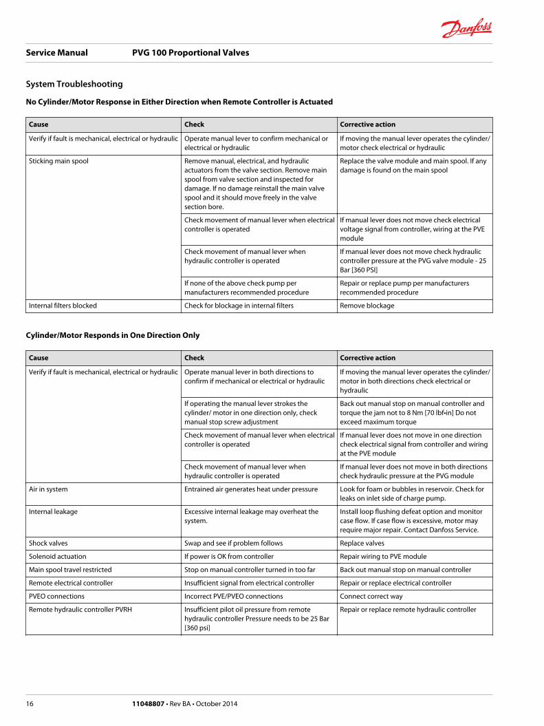
No Cylinder/Motor Response in Either Direction when Remote Controller is Actuated
Cause Check Corrective action
Verify if fault is mechanical, electrical or hydraulic Operate manual lever to confirm mechanical orelectrical or hydraulic
If moving the manual lever operates the cylinder/motor check electrical or hydraulic
Sticking main spool Remove manual, electrical, and hydraulicactuators from the valve section. Remove mainspool from valve section and inspected fordamage. If no damage reinstall the main valvespool and it should move freely in the valvesection bore.
Replace the valve module and main spool. If anydamage is found on the main spool
Check movement of manual lever when electricalcontroller is operated
If manual lever does not move check electricalvoltage signal from controller, wiring at the PVEmodule
Check movement of manual lever whenhydraulic controller is operated
If manual lever does not move check hydrauliccontroller pressure at the PVG valve module - 25Bar [360 PSI]
If none of the above check pump permanufacturers recommended procedure
Repair or replace pump per manufacturersrecommended procedure
Internal filters blocked Check for blockage in internal filters Remove blockage
Cylinder/Motor Responds in One Direction Only
Cause Check Corrective action
Verify if fault is mechanical, electrical or hydraulic Operate manual lever in both directions toconfirm if mechanical or electrical or hydraulic
If moving the manual lever operates the cylinder/motor in both directions check electrical orhydraulic
If operating the manual lever strokes thecylinder/ motor in one direction only, checkmanual stop screw adjustment
Back out manual stop on manual controller andtorque the jam not to 8 Nm [70 lbf•in] Do notexceed maximum torque
Check movement of manual lever when electricalcontroller is operated
If manual lever does not move in one directioncheck electrical signal from controller and wiringat the PVE module
Check movement of manual lever whenhydraulic controller is operated
If manual lever does not move in both directionscheck hydraulic pressure at the PVG module
Air in system Entrained air generates heat under pressure Look for foam or bubbles in reservoir. Check forleaks on inlet side of charge pump.
Internal leakage Excessive internal leakage may overheat thesystem.
Install loop flushing defeat option and monitorcase flow. If case flow is excessive, motor mayrequire major repair. Contact Danfoss Service.
Shock valves Swap and see if problem follows Replace valves
Solenoid actuation If power is OK from controller Repair wiring to PVE module
Main spool travel restricted Stop on manual controller turned in too far Back out manual stop on manual controller
Remote electrical controller Insufficient signal from electrical controller Repair or replace electrical controller
PVEO connections Incorrect PVE/PVEO connections Connect correct way
Remote hydraulic controller PVRH Insufficient pilot oil pressure from remotehydraulic controller Pressure needs to be 25 Bar[360 psi]
Repair or replace remote hydraulic controller
Service Manual PVG 100 Proportional Valves
System Troubleshooting
16 11048807 • Rev BA • October 2014

Main Valve Spool Moves without Oil Passing to Cylinder/Motor
Cause Check Corrective action
Insufficient oil supply to valve Check the pump per manufacturers procedure Repair or replace pump per manufacturersprocedure
Optional pressure compensator in valve sectionnot functioning
Check compensator spool Replace spool
Insufficient load pressure at compensator springchamber
LS drilling holes plugged Clean or replace
Cylinder/motor load too high for pressure settingof the system
Check pressure at the valve If pressure is set to spec. per valve lower load oncylinder/motor
Blocked LS galleries Inspect for blockage in LS galleries Remove blockage in LS galleries
Shuttle valve faulty Inspect shuttle valve Repair or replace
Blocked LS lines to pump controller Inspect LS lines from PCG to pump controller Remove blockage in LS lines from the PVG valveto pump controller
Oil bypassing at shock valve/anticavitation checkvalve
Check if stuck open or damaged Replace valve
Internal leakage in cylinder/motor Inspect for by-passing of oil per cylinder/motormanufacture per manufactures procedure
Repair or replace cylinder/motor permanufactures procedure
Too much leakage in LS spool in pump control Check bleed orifice in LS control Use a LS pump control with no bleed orifice
Load too high for system Check for proper system pressure Adjust pressure to valve specification
Internal leakage in cylinder/motor Inspect for bypassing of oil per cylinder/motormanufacturer specification
Repair or replace cylinder/motor
Shock valve or anti-cavitation check valve faulty Inspect for damage and contamination Repair or replace cylinder/motor
System relief valve pressure set too low for load Install pressure gauge and check pressure Adjust pressure to system specification Lowerload
Cylinder/motor load too high for pressuresettings of system
Check load pressure at PVB-LS port Reduce load pressure if exceeds maximumpressure limit of the system
Maximum system pressure should be approx. 25Bar [365 PSI] above highest load pressure
Adjust maximum system pressure if necessary
Check pump pressure compensator setting Adjust pump pressure compensator setting ifnecessary
Cylinder/Motor Operates without Remote Controller being Operated
Cause Check Corrective action
Spool control tension rod loose Confirm torque on spool control tension rod Torque to 8 Nm [70 lbf•in]
Electrical feedback transducer not in neutralposition
Check the feedback pin in the PVE. It should beloose
Replace module
Remote electrical controller neutral positionswitch faulty
Disconnect the connection at the PVE. It shouldcome back to neutral
Repair or replace faulty switch or wiring atremote controller
Sticking pressure control valve in remotehydraulic controller
Disconnect the hydraulic signal line from valve Repair or replace faulty remote hydrauliccontroller
Sticking main spool in valve section Remove manual, electrical, and hydraulicactuators from the valve section. Remove mainspool from valve section and inspected fordamage. If no damage reinstall the main valvespool. Spool should move freely in the valvesection bore.
Replace the valve module and main spool if anydamage is found on the main spool
Internal fault in the PVE/PVEH/PVEO PVEO check continuity. All other PVE, check LED(Red means internal error)
Replace faulty PVE/PVEH/PVEO
Service Manual PVG 100 Proportional Valves
System Troubleshooting
11048807 • Rev BA • October 2014 17
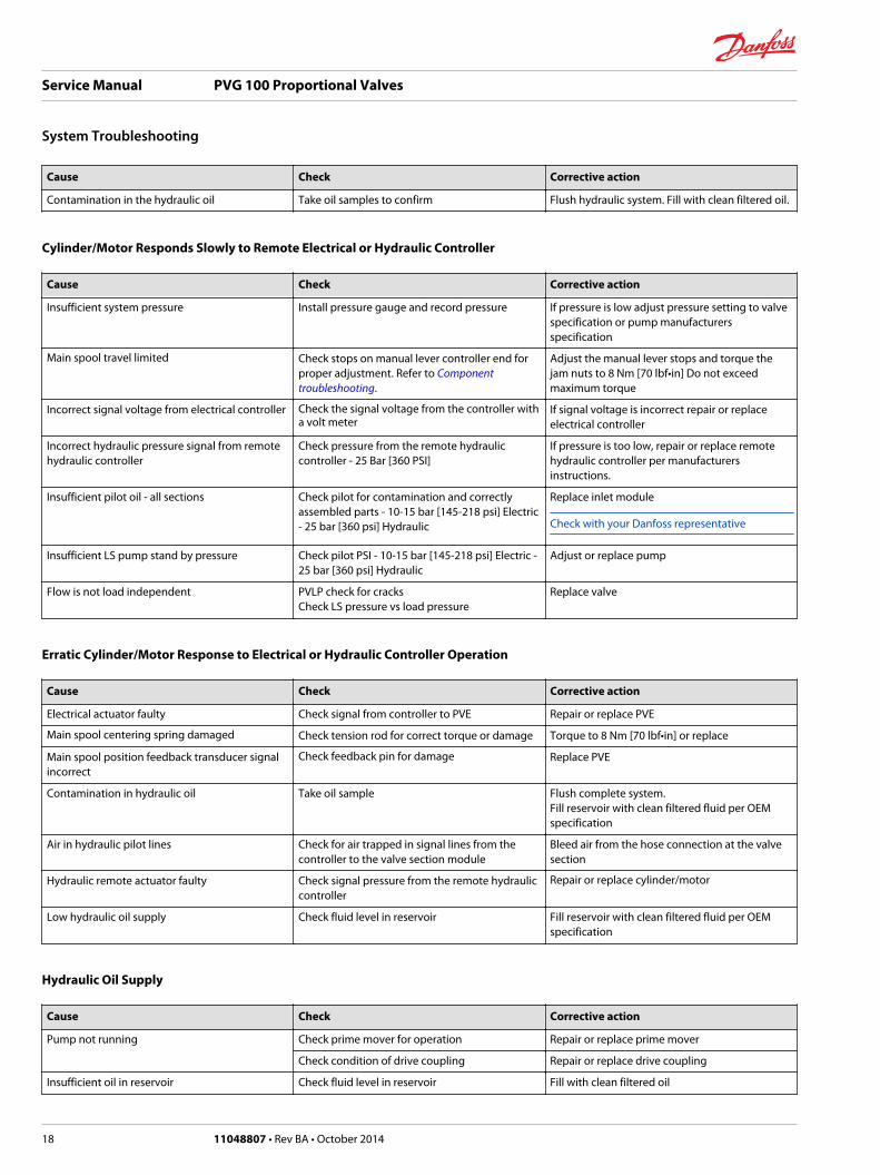
Cause Check Corrective action
Contamination in the hydraulic oil Take oil samples to confirm Flush hydraulic system. Fill with clean filtered oil.
Cylinder/Motor Responds Slowly to Remote Electrical or Hydraulic Controller
Cause Check Corrective action
Insufficient system pressure Install pressure gauge and record pressure If pressure is low adjust pressure setting to valvespecification or pump manufacturersspecification
Main spool travel limited Check stops on manual lever controller end forproper adjustment. Refer to Componenttroubleshooting.
Adjust the manual lever stops and torque thejam nuts to 8 Nm [70 lbf•in] Do not exceedmaximum torque
Incorrect signal voltage from electrical controller Check the signal voltage from the controller witha volt meter
If signal voltage is incorrect repair or replaceelectrical controller
Incorrect hydraulic pressure signal from remotehydraulic controller
Check pressure from the remote hydrauliccontroller - 25 Bar [360 PSI]
If pressure is too low, repair or replace remotehydraulic controller per manufacturersinstructions.
Insufficient pilot oil - all sections Check pilot for contamination and correctlyassembled parts - 10-15 bar [145-218 psi] Electric- 25 bar [360 psi] Hydraulic
Replace inlet module
Check with your Danfoss representative
Insufficient LS pump stand by pressure Check pilot PSI - 10-15 bar [145-218 psi] Electric -25 bar [360 psi] Hydraulic
Adjust or replace pump
Flow is not load independent PVLP check for cracksCheck LS pressure vs load pressure
Replace valve
Erratic Cylinder/Motor Response to Electrical or Hydraulic Controller Operation
Cause Check Corrective action
Electrical actuator faulty Check signal from controller to PVE Repair or replace PVE
Main spool centering spring damaged Check tension rod for correct torque or damage Torque to 8 Nm [70 lbf•in] or replace
Main spool position feedback transducer signalincorrect
Check feedback pin for damage Replace PVE
Contamination in hydraulic oil Take oil sample Flush complete system.Fill reservoir with clean filtered fluid per OEMspecification
Air in hydraulic pilot lines Check for air trapped in signal lines from thecontroller to the valve section module
Bleed air from the hose connection at the valvesection
Hydraulic remote actuator faulty Check signal pressure from the remote hydrauliccontroller
Repair or replace cylinder/motor
Low hydraulic oil supply Check fluid level in reservoir Fill reservoir with clean filtered fluid per OEMspecification
Hydraulic Oil Supply
Cause Check Corrective action
Pump not running Check prime mover for operation Repair or replace prime mover
Check condition of drive coupling Repair or replace drive coupling
Insufficient oil in reservoir Check fluid level in reservoir Fill with clean filtered oil
Service Manual PVG 100 Proportional Valves
System Troubleshooting
18 11048807 • Rev BA • October 2014

Cause Check Corrective action
Leaking or burst supply hose Inspect lines to valve stack Repair or replace damaged hose
Relief valve malfunction Check for contamination and operation of reliefvalve
Repair or replace relief valve
Isolating valves are closed Check that all isolating valves are open and clear
Faulty pump control Check pump compensator for correct operationand setting per pump manufacturers
Repair or replace pump compensator per pumpmanufacturers recommendations
Low standby pressure in PVP - open center pump Check idle standby pressure - 10 Bar [145 PSI] Replace
Check condition of compensator spool spring Replace module due to worn components
Low standby pressure in pump control - variablepump
Check pump LS control for operation and settingStand by pressure should be 15 bar [220 psi]minimum
Repair or replace LS control per pumpmanufacturers procedures
PVP pressure relief valve faulty Check pressure relief valve spool and spring forfreedom of operation
Replace
PVP orifices blocked Check PVP orifices for blockage Remove blockage
Internal filters blocked Check for blockage in internal filters Remove blockage
Supply lines blocked Inspect supply lines for blockages Remove blockage
Internal hydraulic pilot pressure insufficient Inspect pilot oil pressure reducing valve forproper operation
Repair or replace
Blocked LS galleries Check LS galleries for blockage Clean blockage from LS galleries
Shuttle valves faulty Check LS system shuttle valves for wear anddamage
Replace as needed
Check for contamination per specification HPP 030. Refer to Design Guideline for Hydraulic FluidCleanliness, Technical Information Manual 520L0467. If fluid is out of specification, flush hydraulicsystem and fill with clean filtered oil.
Electrical Supply
Cause Check Corrective action
No electrical power Check electrical circuit Repair as needed
Verify emergency stop switch is in the properoperating position
Reset
Neutral position switch faulty Check operation of neutral position switch inremote controller (if connected in circuit) PVRE/PVRES/PVREL
Replace switch
Incorrect signal voltage Check voltage levels at solenoid plug
Proportional operation
Udc: Supply voltage (100%)
Us: Supply signal voltage (25-50-75%)
Ground: Live or ground connection
On-Off Operation
Udc: Supply voltage if selected
Us: Supply voltage if selected
Ground: Live or ground connection
Solenoid valve faulty PVHC Check coil resistance Check data for resistance
Insufficient pilot supply Check pilot pressure - 10-15 bar [145-218 psi]/PVHC 25 bar [360 psi]
Replace
Service Manual PVG 100 Proportional Valves
System Troubleshooting
11048807 • Rev BA • October 2014 19

Cause Check Corrective action
Main spool position feedback transducer signalincorrect
Test oil for contamination and or water content If oil contamination is too high, flush hydraulicsystem or replace oil if necessary. If problempersists change PVE
Incorrect PVE connections Check that the proportional remote electricalcontroller has not been connected to an ON-OFFPVEO solenoid
Connect wires correctly
Hydraulic (remote) Pilot Control Pressure
Cause Check Corrective action
Insufficient pilot pressure Check pilot oil pressure 5-15 bar [72-220 psi]delta between A and B port on remote
PVG100: 5-15 Bar [72-217 PSI]
Insufficient pilot oil supply Check pilot oil flow rate is adequate
Pilot flow should be 1.0 L/min [0.264 GPM] persection
Check pilot lines for blockage Remove blockage
Air in pilot line Check for trapped air in pilot lines Bleed air from pilot lines at PVH
Pilot lines incorrectly sized Check pressure drop Check and reduce length or pilot lines
Increase diameter of pilot lines
Use steel tube for long pilot line runs
Hydraulic remote pilot operator faulty Check operation of hydraulic remote pilotcontroller
Repair or replace
Check supply pressure to hydraulic remotecontroller - minimum 25 bar [360 psi]
Repair or replace
Check and inspect movement of pressure controlvalve in hydraulic controller
Repair per manufacturers procedure, or replace
Check operation of remote hydraulic controller Clean and/or repair as necessary
Service Manual PVG 100 Proportional Valves
System Troubleshooting
20 11048807 • Rev BA • October 2014

Open Center Pressure Relief Valve
Description: Adjustable relief valve. Adjustment range 50 Bar [700 PSI] to 350 Bar [5000 PSI].
Location: The relief is in all PVP Inlet modules
Function: Pilots the unloading valve to open when the load exceeda a set pressure.
Failure mode Cause Corrective action
Will not build pressure Contamination While under pressure, back out to minimumpressure and allow oil to leak by for approx. 5seconds and then readjust to correct pressure -Replace valve
External leaking Damaged seat and poppet Replace complete assembly
Pressure setting is wrong Pressure adjustment backs off (on open centerapplication)
Adjust to model code specification
Serviceability: Non serviceable.
Valve removal tool P/N: 155L6485. Torque to 20 Nm [180 lbf•in].
Closed Center Pressure Relief Valve
Description: Adjustable relief valve. Adjustment range 50 Bar [700 PSI] to 350 Bar [5000 PSI].
Location: The relief is in all PVP Inlet modules
Function: Provides maximum pressure setting below pump pressure setting 30 Bar [450 PSI] Delta forclosed center.
Failure mode Cause Corrective action
Will not build pressure Contamination While under pressure, back out to minimumpressure and allow oil to leak by for approx. 5seconds and then readjust to correct pressure -Replace valve
External leaking Damaged seat and poppet Replace complete assembly
Pressure setting is wrong Pressure adjustment backs off (on open centerapplication)
Adjust to model code specification
Instability when PC and inlet relief has too low ofa delta between them
PC at pump should be set 30 bar above reliefvalve
Adjust to model code specification
Serviceability: Non serviceable.
Valve removal tool P/N: 155L6485. Torque to 20 Nm [180 lbf•in].
Pressure Reducing Pilot Valve
Description: Pressure reducing valve at fixed pressure.
Location: The pressure reducing valve is in all PVP Inlet modules.
Function: Provides 10-15 bar [145-218 psi] internal pressure for electrical (PVE) actuators or provide 25Bar (360 PSI) (PVHC) and supply for external remote hydraulic actuators (HRC). These pressures are onlypresent when the load pressures are high enough to satisfy the required regulated pressure. The opencenter system at low pump flow may only develop 9 Bar (130 PSI)
Service Manual PVG 100 Proportional Valves
PVG 100 Component Troubleshooting
11048807 • Rev BA • October 2014 21

Failure mode Cause Corrective action
Main spools are slow, driven by PVE 13 Bar [190PSI] pilot system
Contamination Disassemble and clean
Pump pressure too low - below 9 Bar [130 PSI] Closed center: System increase stand-by to 13Bar [190 PSI]Open center: Check gear per pump manufactureprocedureCheck system for other components before valveinlet that may provide a path to tank
High T0 pressure. Do not exceed 5 Bar [73 PSI]tank pressure
Clear restrictions in return system.
Oil viscosity 460 mm2/S [2128 SUS] too high(cold oil or incorrect viscosity oil)
Warm up system or replace oil with correctviscosity
Main spools will not move mechanically orelectrical
T0 not being connected to tank or is restricted totank
Connect T0 (PVP) port option to tank or removerestriction
Internal pressure reducing valve partsmisassembled
Reassemble the internal pressure reducing valveparts correctly
PVHC 25 bar [360 psi] pilot system - main spoolsare slow
Contamination Disassemble and clean
Pump pressure too low - below 20 Bar [290 PSI] Closed center: System increase stand-by to 20Bar [290 PSI]Open center: Check gear per pumpmanufacturers procedureCheck system for other components before valveinlet that may provide a path tank
High tank port pressure. Tank pressure shouldnot exceed 5 Bar [73 PSI]
Check for restrictions in return system andremove
Oil viscosity - 460 mm2/S [2128 SUS] too high(cold oil or incorrect viscosity oil)
Warm up system or replace oil with correctviscosity
Serviceability: All internal components can be removed from the cavity, cleaned, inspected andreassembled back into the valve
1. Use a 13 mm hex wrench to remove the plug, and then remove the spring. Spool and cone are notremoveable.
2. Clean all components with clean solvent
3. Correctly reassemble the components back into the cavity and torque the plug to 85 Nm [750lbf•in].Pressure reducing pilot valve
Service Manual PVG 100 Proportional Valves
PVG 100 Component Troubleshooting
22 11048807 • Rev BA • October 2014
13 mm
85 Nm[750 lbf•in]
P107 921E
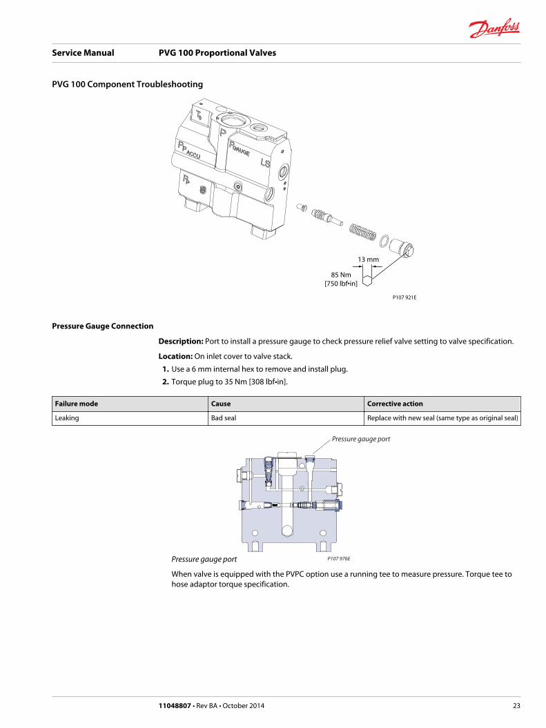
Pressure Gauge Connection
Description: Port to install a pressure gauge to check pressure relief valve setting to valve specification.
Location: On inlet cover to valve stack.
1. Use a 6 mm internal hex to remove and install plug.
2. Torque plug to 35 Nm [308 lbf•in].
Failure mode Cause Corrective action
Leaking Bad seal Replace with new seal (same type as original seal)
Pressure gauge port P107 976E
Pressure gauge port
When valve is equipped with the PVPC option use a running tee to measure pressure. Torque tee tohose adaptor torque specification.
Service Manual PVG 100 Proportional Valves
PVG 100 Component Troubleshooting
11048807 • Rev BA • October 2014 23
PVPC with check valve P107 958E
Check valve
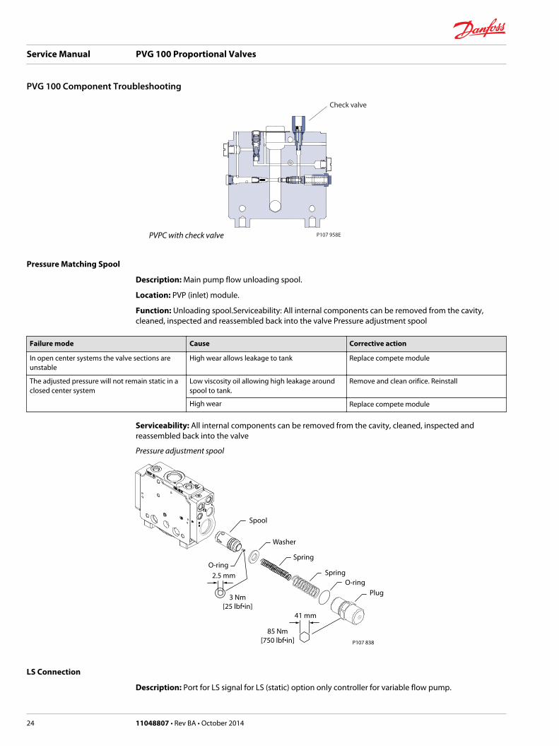
Pressure Matching Spool
Description: Main pump flow unloading spool.
Location: PVP (inlet) module.
Function: Unloading spool.Serviceability: All internal components can be removed from the cavity,cleaned, inspected and reassembled back into the valve Pressure adjustment spool
Failure mode Cause Corrective action
In open center systems the valve sections areunstable
High wear allows leakage to tank Replace compete module
The adjusted pressure will not remain static in aclosed center system
Low viscosity oil allowing high leakage aroundspool to tank.
Remove and clean orifice. Reinstall
High wear Replace compete module
Serviceability: All internal components can be removed from the cavity, cleaned, inspected andreassembled back into the valve
Pressure adjustment spool
P107 838
41 mm
85 Nm[750 lbf•in]
3 Nm[25 lbf•in]
2.5 mm
Plug
Spool
O-ringSpring
Spring
Washer
O-ring
LS Connection
Description: Port for LS signal for LS (static) option only controller for variable flow pump.
Service Manual PVG 100 Proportional Valves
PVG 100 Component Troubleshooting
24 11048807 • Rev BA • October 2014
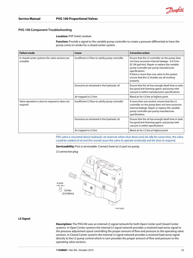
Location: PVP (inlet) module.
Function: Provide a signal to the variable pump controller to create a pressure differential to have thepump come on stroke for a closed center system.
Failure mode Cause Corrective action
In closed center systems the valve sections areunstable
Insufficient LS flow to satisfy pump controller Ensure that the LS controller on the pump doesnot have excessive internal leakage - 0.4 l/min[0.106 gal/min]. Repair or replace the variablepump controller per pump manufacturesspecificationsIf there is more than one valve in the systemensure that the LS shuttles are all workingproperly
Excessive air entrained in the hydraulic oil Ensure that the oil has enough dwell time in tank,has good anti-foaming agent, and pump inletvacuum is within manufacturers specifications
Air trapped in LS line Bleed air for LS line at highest point
Valve operation is slow to respond or does notrespond
Insufficient LS flow to satisfy pump controller If more than one section, ensure that the LScontroller on the pump does not have excessiveinternal leakage. Repair or replace the variablepump controller per pump manufacturesspecifications
Excessive air entrained in the hydraulic oil Ensure that the oil has enough dwell time in tank,has good anti-foaming agent, and pump inletvacuum is within specifications
Air trapped in LS line Bleed air for LS line at highest point
PVG valve is mounted above hydraulic oil reservoir when shut down and sits idle for some time, the valvecould be voided of oil and this would cause the valve to operate erratically and be slow to respond.
Serviceability: Port is serviceable. Connect hose to LS port on pump.
LS connection plug
6 mm
35 Nm [310 lbf•in]
P107 923E
LS Signal
Description: The PVG100 uses an internal LS signal network for both Open Center and Closed Centersystems. In Open Center systems the internal LS signal network provides a resolved load sense signal tothe pressure adjustment spool controlling the proper amount of flow and pressure to the operating valvesections. In Closed Center systems the internal LS signal network provides a resolved load sense signaldirectly to the LS pump control which in turn provides the proper amount of flow and pressure to theoperating valve sections.
Service Manual PVG 100 Proportional Valves
PVG 100 Component Troubleshooting
11048807 • Rev BA • October 2014 25
Location: PVP/PVB Modules.
Function: Directs the highest load pressure to either OC or CC pump control to satisfy the operatingvalve section.
Failure mode Cause Corrective action
No pump pressure developed in one or morevalve sections
LS passages blocked or restricted Disassemble valve. Inspect passages for blockage
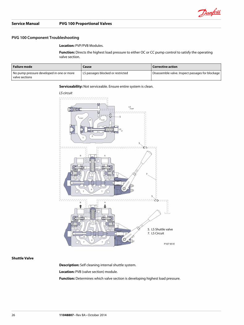
Serviceability: Not serviceable. Ensure entire system is clean.
LS circuit
P107 951E
5
5
5
7
5. LS Shuttle valve7. LS Circuit
Shuttle Valve
Description: Self cleaning internal shuttle system.
Location: PVB (valve section) module.
Function: Determines which valve section is developing highest load pressure.
Service Manual PVG 100 Proportional Valves
PVG 100 Component Troubleshooting
26 11048807 • Rev BA • October 2014

Failure mode Cause Corrective action
Valve sections will not build pressure
Normally it will be one section, but not allsections
Worn shuttle disc Replace complete module (seat is pressed intomodule)
Excessive air entrained in the hydraulic oil Ensure that the oil has enough dwell time in tank,has good anti-foaming agent, and pump inletvacuum is within specifications
Shuttle disk accidentally pushed in Check disk spacing - replace module
Serviceability: Not serviceable. Ensure entire system is clean.
Shuttle valve
P107 841
Ball should movefreely behind disk
Exploded view shows internal parts.Do not disassemble valve.
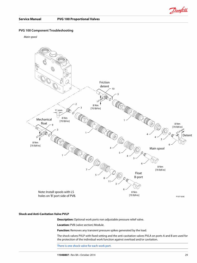
Main Spool
Description: Main directional control.
Location: PVB (valve section) module.
Function: Controls oil flow from pump to work ports A or B.
Failure mode Cause Corrective action
Section will not build pressure in one spooldirection
Load sense passages in spool are blocked Flush out load sense passages in the spool. Spoolwill need to be removed to clean
Main valve spool stuck in valve body (if beingused with electrical actuator)
Refer to Pressure reducing valve Replace PVM and PVE. Be sure that pilot valve isassembled correctly.
Mechanical actuator main valve spool stuck invalve body
Hard particle binding spool in bore Look down into the A and B work ports to see ifthe particle can be removed while the spool is inthe valve body. Replace valve section.
Valve body and spool will need to be replacedper valve specifications
Main spool stuck in valve body Tie rod over torqued Replace tie rod kit which includes section sealsand torque to 28 Nm [248 lbf•in]
Valve stack mounting surface is not flat causing abind on the valve stack
Ensure the mounting surface is flat*
Section will not stroke off Load sense drain holes are plugged Flush out load sense passages in the spool. Spoolwill need to be removed to clean
Service Manual PVG 100 Proportional Valves
PVG 100 Component Troubleshooting
11048807 • Rev BA • October 2014 27
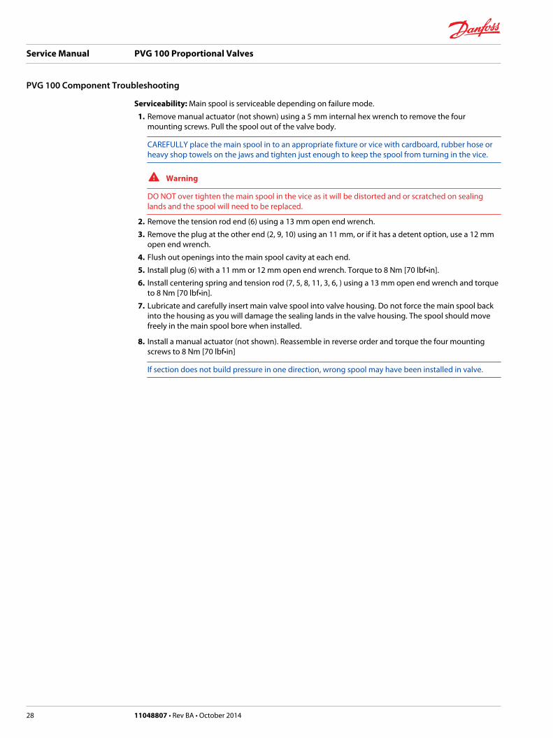
Serviceability: Main spool is serviceable depending on failure mode.
1. Remove manual actuator (not shown) using a 5 mm internal hex wrench to remove the fourmounting screws. Pull the spool out of the valve body.
CAREFULLY place the main spool in to an appropriate fixture or vice with cardboard, rubber hose orheavy shop towels on the jaws and tighten just enough to keep the spool from turning in the vice.
W Warning
DO NOT over tighten the main spool in the vice as it will be distorted and or scratched on sealinglands and the spool will need to be replaced.
2. Remove the tension rod end (6) using a 13 mm open end wrench.
3. Remove the plug at the other end (2, 9, 10) using an 11 mm, or if it has a detent option, use a 12 mmopen end wrench.
4. Flush out openings into the main spool cavity at each end.
5. Install plug (6) with a 11 mm or 12 mm open end wrench. Torque to 8 Nm [70 lbf•in].
6. Install centering spring and tension rod (7, 5, 8, 11, 3, 6, ) using a 13 mm open end wrench and torqueto 8 Nm [70 lbf•in].
7. Lubricate and carefully insert main valve spool into valve housing. Do not force the main spool backinto the housing as you will damage the sealing lands in the valve housing. The spool should movefreely in the main spool bore when installed.
8. Install a manual actuator (not shown). Reassemble in reverse order and torque the four mountingscrews to 8 Nm [70 lbf•in]
If section does not build pressure in one direction, wrong spool may have been installed in valve.
Service Manual PVG 100 Proportional Valves
PVG 100 Component Troubleshooting
28 11048807 • Rev BA • October 2014
Main spool
P107 924E
12 mm
8 Nm [70 lbf·in]
Float B-port
Mechanical float
6
3
8 Nm [70 lbf·in]
11
7
8 5
1
3
9
3
1
11 mm
8 Nm[70 lbf·in]
Main spool
8 Nm [70 lbf·in]
2
6
3
4
5 4
12 mm
Detent
Frictiondetent
8 Nm [70 lbf·in]
8 Nm[70 lbf·in]
3
10
6
3
4
1
4
12.5 mm
Note: Install spools with LS holes on ‘B’ port side of PVB.
Shock and Anti-Cavitation Valve PVLP
Description: Optional work ports non adjustable pressure relief valve.
Location: PVB (valve section) Module.
Function: Removes any transient pressure spikes generated by the load.
The shock valves PVLP with fixed setting and the anti-cavitation valves PVLA on ports A and B are used forthe protection of the individual work function against overload and/or cavitation.
There is one shock valve for each work port.
Service Manual PVG 100 Proportional Valves
PVG 100 Component Troubleshooting
11048807 • Rev BA • October 2014 29

Failure mode Cause Corrective action
Will not build pressure in A or B port Valve may be damaged and not able to seal Replace with correct part number per valvespecification
Serviceability: This valve may be disassembled and cleaned, however, internal parts are not availableseparately. If you suspect valve malfunction, replace with a new valve and test system operation.
PVLP valve
P107 924E
7PVLP
9
8PVLA
10
10
10
13 mm
40 Nm[354 lbf•in]
Pressure Compensator
Description: Maintains a pump margin across the compensator.
Location: PVB (Valve section) Module.
Function: In a pressure-compensated basic module the compensator maintains a constant pressure dropacross the main spool – both when the load changes and when a module with a higher load pressure isactuated.
Failure mode Cause Corrective action
Valve section unstable flow High wear allows leakage Replace complete module
Serviceability: This valve may be disassembled and cleaned, however, internal parts are not availableseparately. If you suspect valve malfunction, replace with a new valve and test system operation.
Pressure compensator valve
P107 975E
Pressure Compensator Spool
Service Manual PVG 100 Proportional Valves
PVG 100 Component Troubleshooting
30 11048807 • Rev BA • October 2014
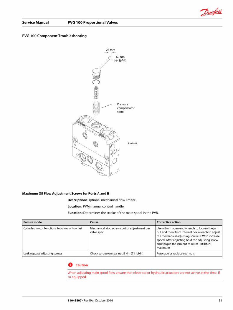
P107 843
27 mm
60 Nm[44 lbf•ft]
Pressure compensator spool
Maximum Oil Flow Adjustment Screws for Ports A and B
Description: Optional mechanical flow limiter.
Location: PVM manual control handle.
Function: Determines the stroke of the main spool in the PVB.
Failure mode Cause Corrective action
Cylinder/motor functions too slow or too fast Mechanical stop screws out of adjustment pervalve spec.
Use a 8mm open end wrench to loosen the jamnut and then 3mm internal hex wrench to adjustthe mechanical adjusting screw CCW to increasespeed. After adjusting hold the adjusting screwand torque the jam nut to 8 Nm [70 lbf•in]maximum
Leaking past adjusting screws Check torque on seal nut 8 Nm [71 lbf•in] Retorque or replace seal nuts
C Caution
When adjusting main spool flow ensure that electrical or hydraulic actuators are not active at the time, ifso equipped.
Service Manual PVG 100 Proportional Valves
PVG 100 Component Troubleshooting
11048807 • Rev BA • October 2014 31
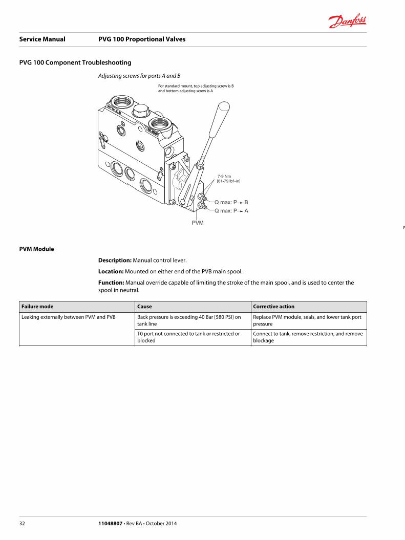
Adjusting screws for ports A and B
P107 816E
For standard mount, top adjusting screw is Band bottom adjusting screw is A
PVM Module
Description: Manual control lever.
Location: Mounted on either end of the PVB main spool.
Function: Manual override capable of limiting the stroke of the main spool, and is used to center thespool in neutral.
Failure mode Cause Corrective action
Leaking externally between PVM and PVB Back pressure is exceeding 40 Bar [580 PSI] ontank line
Replace PVM module, seals, and lower tank portpressure
T0 port not connected to tank or restricted orblocked
Connect to tank, remove restriction, and removeblockage
Service Manual PVG 100 Proportional Valves
PVG 100 Component Troubleshooting
32 11048807 • Rev BA • October 2014
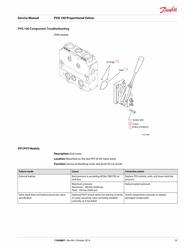
PVM module
P107 848
O-rings
Seal
Screw (x4)
5 mm8 Nm [70 lbf•in]
PVT/PVTI Module
Description: End cover.
Location: Mounted on the last PVT of the valve stack.
Function: Serves as blanking cover and drain for LS circuit.
Failure mode Cause Corrective action
External leaking Back pressure is exceeding 40 Bar [580 PSI] ontank line
Replace PVS module, seals, and lower tank linepressure
Maximum pressure:Aluminum - 300 bar [4500 psi]Steel - 350 bar [5000 psi]
Reduce system pressure
Valve stack does not build pressure per valvespecification
Optional PVLP (shock valve) not seating correctlyin cavity caused by valve not being installedcorrectly, or it has failed
Install components correctly, or replacedamaged components
Service Manual PVG 100 Proportional Valves
PVG 100 Component Troubleshooting
11048807 • Rev BA • October 2014 33
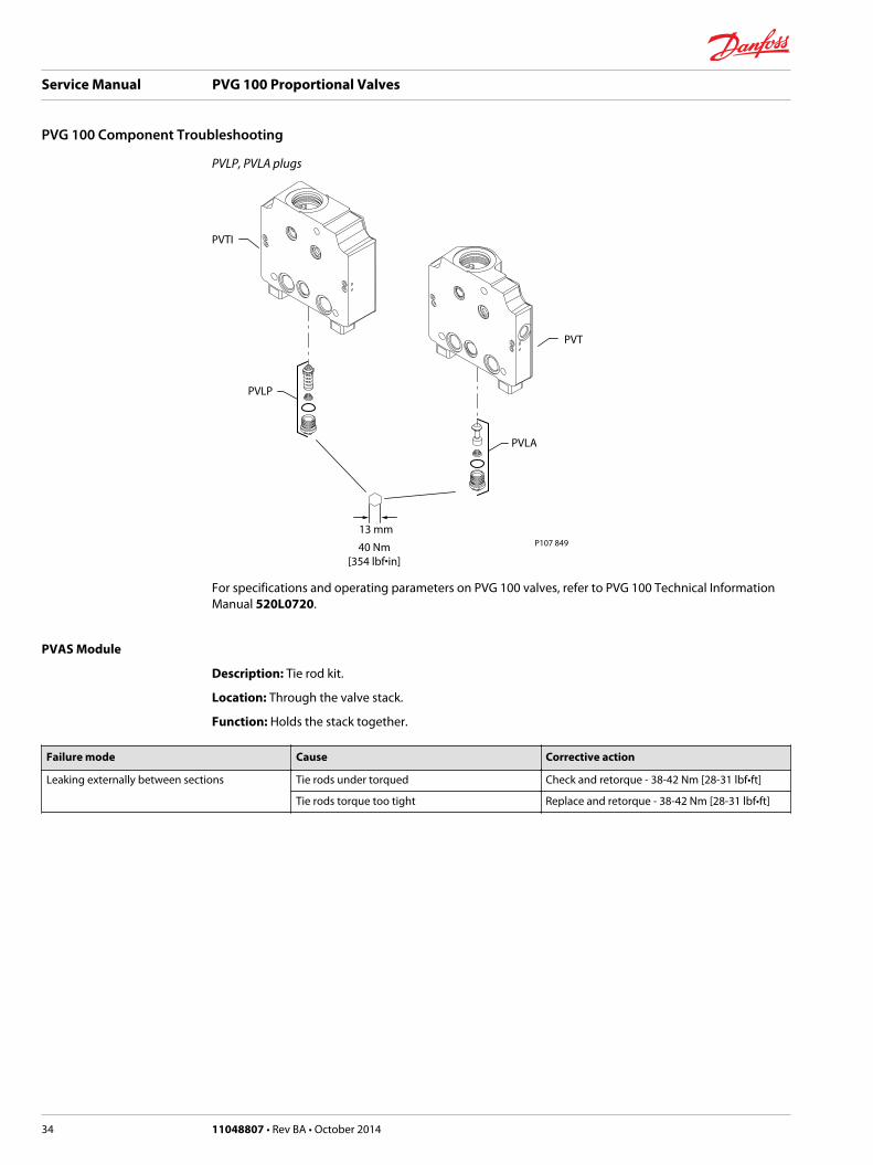
PVLP, PVLA plugs
P107 849
PVLP
PVLA
13 mm
40 Nm[354 lbf•in]
PVTI
PVT
For specifications and operating parameters on PVG 100 valves, refer to PVG 100 Technical InformationManual 520L0720.
PVAS Module
Description: Tie rod kit.
Location: Through the valve stack.
Function: Holds the stack together.
Failure mode Cause Corrective action
Leaking externally between sections Tie rods under torqued Check and retorque - 38-42 Nm [28-31 lbf•ft]
Tie rods torque too tight Replace and retorque - 38-42 Nm [28-31 lbf•ft]
Service Manual PVG 100 Proportional Valves
PVG 100 Component Troubleshooting
34 11048807 • Rev BA • October 2014
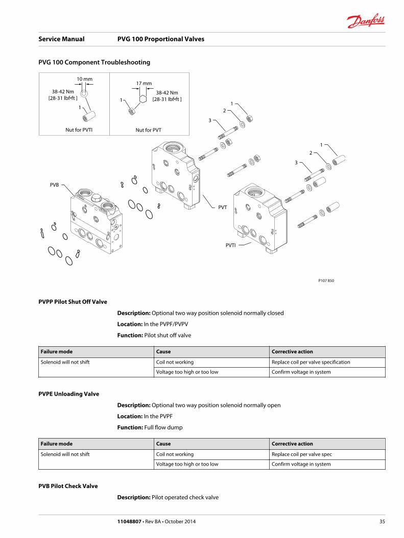
P107 850
PVT
PVB
3
2
38-42 Nm[28-31 lbf•ft ]
1
10 mm
1
17 mm
38-42 Nm[28-31 lbf•ft ]
Nut for PVTI Nut for PVT
PVTI
3
2
1
1
PVPP Pilot Shut Off Valve
Description: Optional two way position solenoid normally closed
Location: In the PVPF/PVPV
Function: Pilot shut off valve
Failure mode Cause Corrective action
Solenoid will not shift Coil not working Replace coil per valve specification
Voltage too high or too low Confirm voltage in system
PVPE Unloading Valve
Description: Optional two way position solenoid normally open
Location: In the PVPF
Function: Full flow dump
Failure mode Cause Corrective action
Solenoid will not shift Coil not working Replace coil per valve spec
Voltage too high or too low Confirm voltage in system
PVB Pilot Check Valve
Description: Pilot operated check valve
Service Manual PVG 100 Proportional Valves
PVG 100 Component Troubleshooting
11048807 • Rev BA • October 2014 35
Location: In the PVB
Function: Low leakage on the work ports
Failure mode Cause Corrective action
Internal leakage Component wear Replace module
Contamination Replace module
PVEH, PVES, Electrical Actuators
Description: Proportional electrical actuator.
Location: On the end of the main spool of the PVB.
Function: Convert an electrical command to move the main spool to a set position.
Troubleshooting Considerations
Wiring Check: It is highly possible that in the case of one PVE failing that there could be a poorconnection between the joystick and the PVE in question. The PVE is reverse polarity protected andsuppression protected; however an intermittent connection could degrade the input electronics to apoint of failure. Inspect all wiring and connectors for corrosion and or pinch points.
Hirshman Receptacle and Mating Connector: Each PVE is supplied with a field installable 4-pinHirshman mating connector and gasket. It is recommended that the gasket be installed between themating connector and PVE receptacle also the rubber grommet be sealed around a multi-wire jacket inorder to seal off moisture from the wiring connections. The PVE is rated for IP65 only when the Hirshmanconnector is sealed.
Temperature Capability: The PVE is rated for 1000 hours @ 160 °F. ambient temperature. Oiltemperature wise, the area of the valve that creates the highest horsepower loss usually creates thehighest temperature in the system. If one PVE section is operated more frequently than others this wouldcreate more heat than any other part of the valve. Under these conditions it is extremely important toinsure that the hydraulic system is well cooled. Oil temperature measurements at the reservoir and at thecenter of the PVG100 valve stack. The valve should be mounted to provide the best ventilation for thePVE electronics. Poor filtration and low fluid levels may also add to temperature.
Failure mode Cause Corrective action
Does not work in either direction LED is green No control voltage from the electrical controller While under pressure, back out to minimumpressure and allow oil to leak by for approx. 5seconds and then readjust to correct pressure -Replace valve
Command pin wire in mating connector isbroken
Repair broken wire
Connector corroded - This condition is caused bywater ingression or ground connection
Replace PVE and mating connector
Does not work in either direction LED is off No power from the battery Check power to electrical actuator
Power pin wire in mating connector is broken Repair broken wire
Connector corroded - This condition is caused bywater ingression or ground connection
Replace PVE and mating connector
Ground connection must be hard wired straightfrom the battery or from the electrical controller
Repair ground connection
LED is flashing Red Control signal is out of range Check wiring harness for short
Service Manual PVG 100 Proportional Valves
PVG 100 Component Troubleshooting
36 11048807 • Rev BA • October 2014
Failure mode Cause Corrective action
Works in one direction (Assuming that themanual control lever and the main spool movefreely both directions)
No control voltage from the electrical controller Ensure voltage from the electrical controllerexists for that direction
Lack of voltage to actuator (Minimum voltage 11volts for 12 volt system and 22 volts for 24 voltsystem)
Check system voltage
Electrical actuator is defective Replace electrical actuator per spec. on the valve
Works intermittently (if LED is green it indicates along on/off
Loose connection between the electricalactuator and controller
Repair connector
Electrical actuator is defective Replace electrical actuator per spec. on the valve
Short in wiring harness Repair wiring harness
Works with no command from controller Short in wiring harness Repair wiring harness
Electrical actuator position feed back out ofadjustment
Replace the electrical actuator per valve spec.
Fine particulate contamination Replace PVE or electric actuator per valve specs.
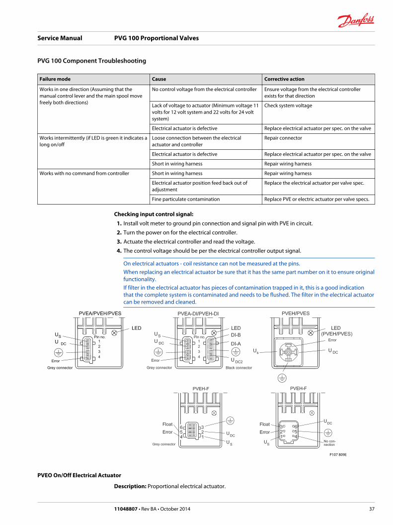
Checking input control signal:1. Install volt meter to ground pin connection and signal pin with PVE in circuit.
2. Turn the power on for the electrical controller.
3. Actuate the electrical controller and read the voltage.
4. The control voltage should be per the electrical controller output signal.
On electrical actuators - coil resistance can not be measured at the pins.When replacing an electrical actuator be sure that it has the same part number on it to ensure originalfunctionality.If filter in the electrical actuator has pieces of contamination trapped in it, this is a good indicationthat the complete system is contaminated and needs to be flushed. The filter in the electrical actuatorcan be removed and cleaned.
P107 809E
PVEO On/Off Electrical Actuator
Description: Proportional electrical actuator.
Service Manual PVG 100 Proportional Valves
PVG 100 Component Troubleshooting
11048807 • Rev BA • October 2014 37

Location: On the end of the main spool of the PVB.
Function: Convert an electrical command to move the main spool to a set position.
Failure mode Cause Corrective action
Does not work in either direction LED is green No control voltage from the electrical controller Check voltage from the electrical controllerResistance check (measures between pin 2 andground):17 OHMs for 12 volt systems63 OHMs for 24 volt systems
Command pin wire in mating connector isbroken
Repair broken wire
Connector corroded Replace PVE and mating connector - Thiscondition is caused by water ingression orground connection
24 volt electrical actuator used on a 12 voltsystem
Replace with the correct electrical actuator for a24 volt system
No power from the battery Check power to electrical actuator
Power pin wire in mating connector is broken Repair broken wire
Ground connection must be hard wired straightfrom the battery or from the electrical controller
Repair ground connection
Works in one direction (Assuming that themanual control lever and the main spool movesfreely both directions)
No control voltage from the electrical controller Ensure voltage from the electrical controllerexists for that direction
Lack of voltage to actuator (Minimum voltage 11volts for 12 volt system and 22 volts for 24 voltsystem
Check system voltage
Electrical actuator is defective Replace electrical actuator per spec. on the valve
Works intermittently (if LED is green it indicates along on/off
Loose connection between the electricalactuator and controller
Repair connector
Electrical actuator is defective Replace electrical actuator per spec. on the valve
Short in wiring harness Repair wiring harness
Works with no command from controller Fine contamination Replace the electrical actuator per valve spec.and flush the complete system and fill withfiltered oil
Short in wiring harness Repair wiring harness
PVPC Plug for External Pilot Control
Description: Pilot oil supply from another pump.
Location: On the top of the PVP.
Function: Provides a hydraulic pilot supply to the valve stack.
Failure mode Cause Corrective action
Main spool moves slow, or not at all, in allsections
External hydraulic pilot pressure is too low Check external hydraulic pressure from pilotpump and/or restrictions
Service Manual PVG 100 Proportional Valves
PVG 100 Component Troubleshooting
38 11048807 • Rev BA • October 2014

PVPC plug for external pilot
P107 958E
Check valve
PVMR Friction Module
Description: Mechanical friction hold.
Location: Mounted on main spool in the PVB.
Function: Infinite mechanical positioning of the main spool.
Failure mode Cause Corrective action
Flow changes Excessive flow across the main spool Reduce flow
Vibration Reduce vibration
Broken spring Replace broken springs
Flow changes or will not stay in detent Check for proper assembly of parts Install parts correctly per specification sheet
Service Manual PVG 100 Proportional Valves
PVG 100 Component Troubleshooting
11048807 • Rev BA • October 2014 39
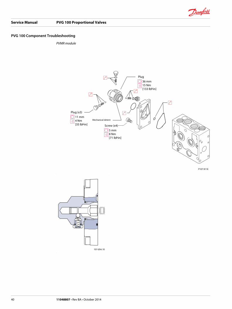
PVMR module
P107 811E
Mechanical detent11 mm4 Nm [35 lbf•in]
Plug (x3)
5 mm8 Nm [71 lbf•in]
Screw (x4)
36 mm15 Nm [133 lbf•in]
Plug
Service Manual PVG 100 Proportional Valves
PVG 100 Component Troubleshooting
40 11048807 • Rev BA • October 2014
Service Manual PVG 100 Proportional Valves
11048807 • Rev BA • October 2014 41
Service Manual PVG 100 Proportional Valves
42 11048807 • Rev BA • October 2014

Service Manual PVG 100 Proportional Valves
11048807 • Rev BA • October 2014 43
Danfoss Power Solutions is a global manufacturer and supplier of high-quality hydraulic andelectronic components. We specialize in providing state-of-the-art technology and solutionsthat excel in the harsh operating conditions of the mobile off-highway market. Building onour extensive applications expertise, we work closely with our customers to ensureexceptional performance for a broad range of off-highway vehicles.
We help OEMs around the world speed up system development, reduce costs and bringvehicles to market faster.
Danfoss – Your Strongest Partner in Mobile Hydraulics.
Go to www.powersolutions.danfoss.com for further product information.
Wherever off-highway vehicles are at work, so is Danfoss. We offer expert worldwide supportfor our customers, ensuring the best possible solutions for outstanding performance. Andwith an extensive network of Global Service Partners, we also provide comprehensive globalservice for all of our components.
Please contact the Danfoss Power Solution representative nearest you.
Local address:
Danfoss Power Solutions GmbH & Co. OHGKrokamp 35D-24539 Neumünster, GermanyPhone: +49 4321 871 0
Danfoss Power Solutions ApSNordborgvej 81DK-6430 Nordborg, DenmarkPhone: +45 7488 2222
Danfoss Power Solutions US Company2800 East 13th StreetAmes, IA 50010, USAPhone: +1 515 239 6000
Danfoss Power Solutions(Shanghai) Co., Ltd.Building #22, No. 1000 Jin Hai RdJin Qiao, Pudong New DistrictShanghai, China 201206Phone: +86 21 3418 5200
Danfoss can accept no responsibility for possible errors in catalogues, brochures and other printed material. Danfoss reserves the right to alter its products without notice. This also applies toproducts already on order provided that such alterations can be made without changes being necessary in specifications already agreed.All trademarks in this material are property of the respective companies. Danfoss and the Danfoss logotype are trademarks of Danfoss A/S. All rights reserved.
11048807 • Rev BA • October 2014 www.danfoss.com © Danfoss A/S, 2013
Products we offer:
• Bent Axis Motors
• Closed Circuit Axial PistonPumps and Motors
• Displays
• Electrohydraulic PowerSteering
• Electrohydraulics
• Hydraulic Power Steering
• Integrated Systems
• Joysticks and ControlHandles
• Microcontrollers andSoftware
• Open Circuit Axial PistonPumps
• Orbital Motors
• PLUS+1® GUIDE
• Proportional Valves
• Sensors
• Steering
• Transit Mixer Drives
Comatrolwww.comatrol.com
Schwarzmüller-Inverterwww.schwarzmueller-inverter.com
Turolla www.turollaocg.com
Valmovawww.valmova.com
Hydro-Gearwww.hydro-gear.com
Daikin-Sauer-Danfosswww.daikin-sauer-danfoss.com