Embed Size (px)
Citation preview
155
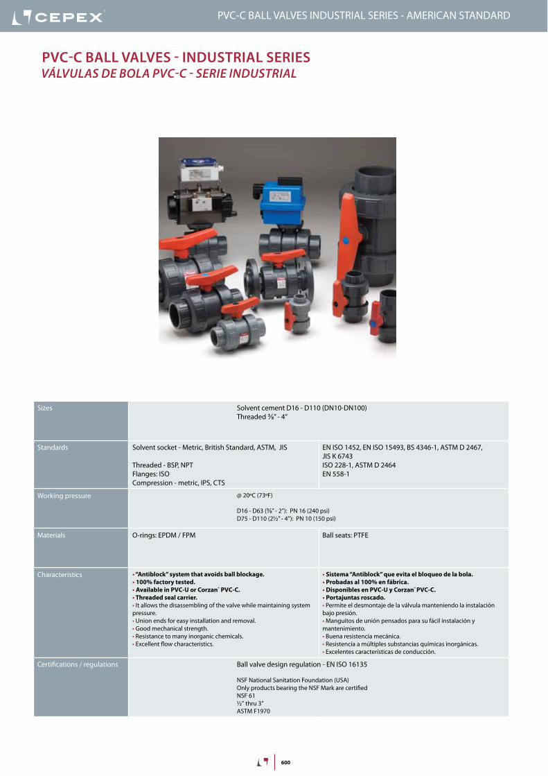
Pvc-U Ball valveS - inDUStrial SerieS válvulaS de bola Pvc-u - Serie induSTrial
Sizes Solvent cement D16 - D110 (DN10-DN100)Threaded ⅜” - 4”
Standards Solvent socket - Metric, British Standard, ASTM, JIS
Threaded - BSP, NPTFlanges: ISOCompression - metric, IPS, CTS
EN ISO 1452, EN ISO 15493, BS 4346-1, ASTM D 2467, JIS K 6743ISO 228-1, ASTM D 2464EN558 Serie 1 DIN 3202-1
Working pressure @ 20ºC (73ºF)
D16 - D63 (⅜” - 2”): PN 16 (240 psi)D75 - D110 (2½” - 4”): PN 10 (150 psi)
Materials O-rings: EPDM / FPM Ball seats: PTFE
Characteristics • “Antiblock” system that avoids ball blockage.• 100% factory tested.• Available in PVC-U or Corzan® PVC-C.• Threaded seal carrier.• It allows the disassembling of the valve while maintaining system pressure.• Union ends for easy installation and removal.• Good mechanical strength.• Resistance to many inorganic chemicals.• Excellent flow characteristics.
• Sistema “Antiblock” que evita el bloqueo de la bola.• Probadas al 100% en fábrica.• Disponibles en PVC-U y Corzan® PVC-C.• Portajuntas roscado.• Permite el desmontaje de la válvula manteniendo la instalación bajo presión.• Manguitos de unión pensados para su fácil instalación y mantenimiento.• Buena resistencia mecánica.• Resistencia a múltiples substancias químicas inorgánicas.• Excelentes características de conducción.
Certifications / regulations Ball valve design regulation - EN ISO 16135
NSF National Sanitation Foundation (USA)Only products bearing the NSF Mark are certifiedNSF 61½” thru 3”ASTM F1970
PVC-U BALL VALVES INDUSTRIAL SERIES

156
FIG. Parts Despiece Material
1 Shaft Eje PVC-U
2 Ball Bola PVC-U
3 Union nut Tuerca PVC-U
4 Handle Conjunto maneta PP
5 End connector Manguito enlace PVC-U
6 Ball seat Asiento bola PTFE
7 Shaft o-ring Junta eje EPDM / FPM
8 Body o-ring Junta cuerpo EPDM / FPM
9 Dampener seal Junta amortiguación EPDM / FPM
10 End connector o-ring Junta manguito EPDM / FPM
11 Adjusting tool Llave de regulación ABS
12 Body Cuerpo PVC-U
13 Seal-carrier Portajuntas PVC-U
1
2
3
4
9
6
7
9
5
810
3
5
6
12
13
10
11
20 years / water flow20 années / fluide de l�eau20 años / fluido de agua20 anos / caudal de água
18
16
14
12
10
8
6
4
2
0
0 10 20 30 40 50 60
Temperature / Température / Temperatura / Temperatura
Pres
sure
/Pre
ssio
n/ P
resió
n/ P
ress
ão
°C32 50 68 86 104 122 140 °F
barpsi270
240
210
180
150
120
90
60
30
0
DN
15
-3/8
”-½
”
DN
20
-¾
”DN
25
-1”
DN
32
-1¼
”
DN
40
-1½
”DN
50
-2”
DN
65
-2½
”
0,1
10 (l/min)
bar
Kv (l/min , p = 1 bar)
0,01
0,001
1
100 1.000 10.000
DN
80
-3”
DN
100
-4”
2,64 (GPM)26,42 264 2.642
1,50
0,15
0,01
15,0
psi
Flow / Débit / Caudal / Caudal
Pres
sure
loss
/Per
tede
char
ge/
Pérd
ida
deca
rga
/Per
dasd
eca
rga
PN 10
PN 16
PreSSUre / teMPeratUre graPhdiaGraMa PreSión / TeMPeraTura
Pres
sure
/ Pr
esió
n
Temperature / Temperatura
vida útil: 25 añosPresión hidrostática máxima que un com-ponente es capaz de soportar en servicio continuo (sin sobrepresión)
PVC-U BALL VALVES INDUSTRIAL SERIES
Life: 25 yearsHydrostatic maximum pressure a comp-nent may outstand in continous service (without overpressure)
157
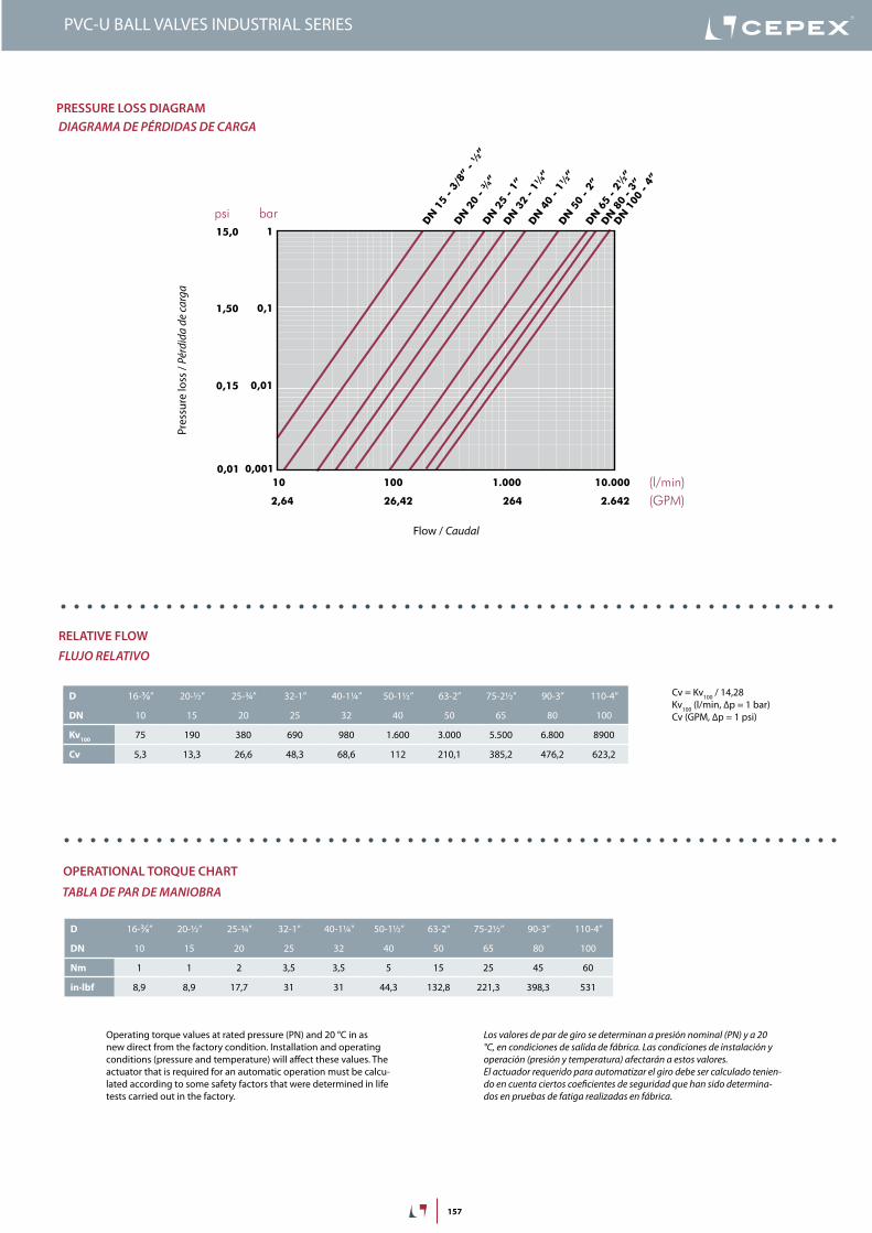
Cv = Kv100 / 14,28Kv100 (l/min, ∆p = 1 bar)Cv (GPM, ∆p = 1 psi)
2,64 26,42 264 2.642
20 years / water flow20 années / fluide de l�eau20 años / fluido de agua20 anos / caudal de água
Temperature / Température / Temperatura / Temperatura
P res
sure
/Pre
ssio
n/ P
resió
n/ P
ress
ão
18
16
14
12
10
8
6
4
2
0
0 10 20 30 40 50 60 70 80 90 °C32 50 68 86 104 122 140 158 176 194 °F
barpsi
DN
15
-3/8
”-½
”
DN
20
-¾
”DN
25
-1”
DN
32
-1¼
”
DN
40
-1½
”DN
50
-2”
DN
65
-2½
”
0,1
10 (l/min)
bar
Kv (l/min , p = 1 bar)
0,01
0,001
1
100 1.000 10.000
DN
80
-3”
DN
100
-4”
(GPM)
1,50
0,15
0,01
15,0
psi
Flow / Débit / Caudal / Caudal
PVC-U
PVC-C
270
240
210
180
150
120
90
60
30
0
Pres
sure
loss
/Per
tede
char
ge/
Pérd
ida
deca
rga
/Per
dasd
eca
rga
PN 10
PN 16
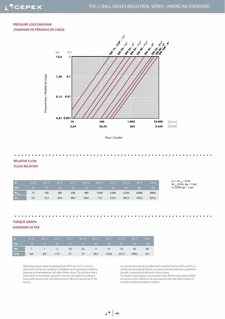
D 16-⅜” 20-½” 25-¾” 32-1” 40-1¼” 50-1½” 63-2” 75-2½” 90-3” 110-4”
DN 10 15 20 25 32 40 50 65 80 100
Kv100 75 190 380 690 980 1.600 3.000 5.500 6.800 8900
Cv 5,3 13,3 26,6 48,3 68,6 112 210,1 385,2 476,2 623,2
PreSSUre lOSS DiagraMdiaGraMa de PÉrdidaS de carGa
relative FlOWFluJo relaTivo
OPeratiOnal tOrQUe chart
Tabla de Par de Maniobra
Pres
sure
loss
/ Pé
rdid
a de
carg
a
Flow / caudal
Operating torque values at rated pressure (PN) and 20 °C in as new direct from the factory condition. Installation and operating conditions (pressure and temperature) will affect these values. The actuator that is required for an automatic operation must be calcu-lated according to some safety factors that were determined in life tests carried out in the factory.
Los valores de par de giro se determinan a presión nominal (Pn) y a 20 °c, en condiciones de salida de fábrica. Las condiciones de instalación y operación (presión y temperatura) afectarán a estos valores. el actuador requerido para automatizar el giro debe ser calculado tenien-do en cuenta ciertos coeficientes de seguridad que han sido determina-dos en pruebas de fatiga realizadas en fábrica.
D 16-⅜” 20-½” 25-¾” 32-1” 40-1¼” 50-1½” 63-2” 75-2½” 90-3” 110-4”
DN 10 15 20 25 32 40 50 65 80 100
Nm 1 1 2 3,5 3,5 5 15 25 45 60
in·lbf 8,9 8,9 17,7 31 31 44,3 132,8 221,3 398,3 531
PVC-U BALL VALVES INDUSTRIAL SERIES
158
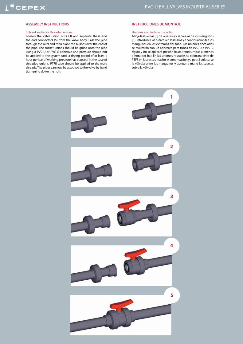
inStrUcciOneS De MOntaje
Uniones encoladas o roscadasAfloje las tuercas (3) de la válvula y sepárelas de los manguitos (5). Introduzca las tuercas en los tubos y a continuación fije los manguitos en los extremos del tubo. Las uniones encoladas se realizarán con un adhesivo para tubos de PVC-U o PVC-C rígido y no se aplicará presión hasta transcurridas al menos 1 hora por bar. En las uniones roscadas se colocará cinta de PTFE en las roscas macho. A continuación ya podrá colocarse la válvula entre los manguitos y apretar a mano las tuercas sobre la válvula.
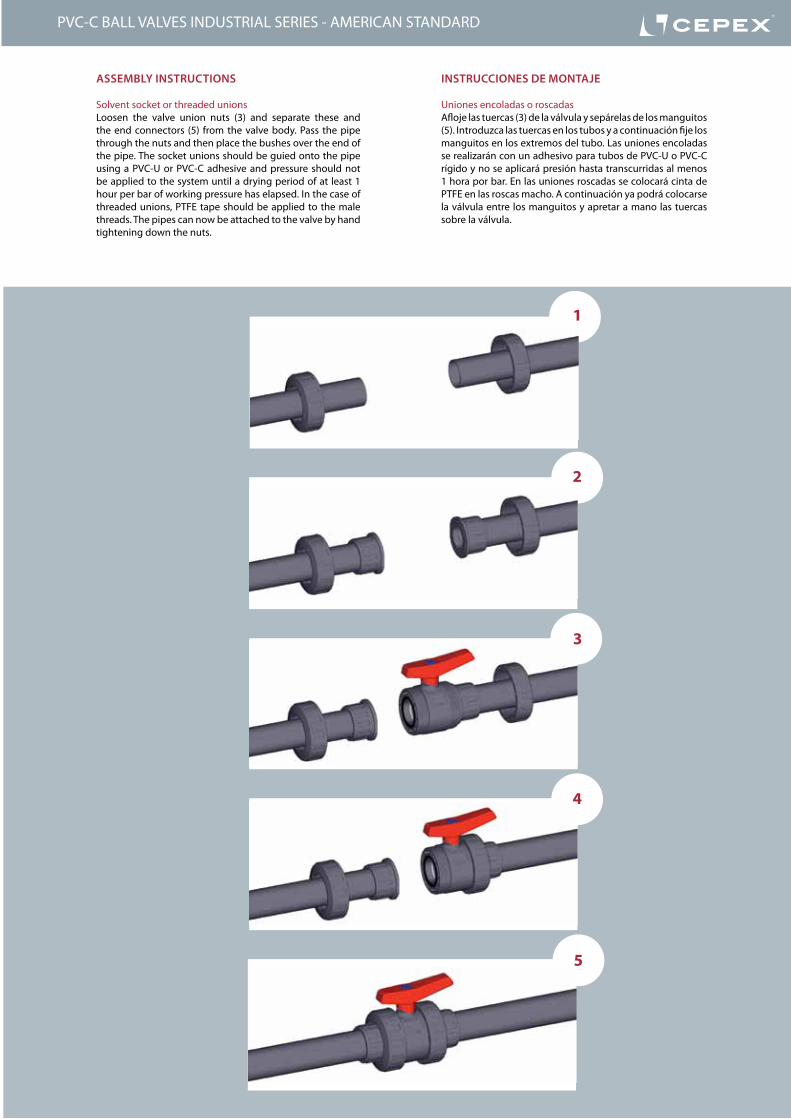
aSSeMBly inStrUctiOnS
Solvent socket or threaded unionsLoosen the valve union nuts (3) and separate these and the end connectors (5) from the valve body. Pass the pipe through the nuts and then place the bushes over the end of the pipe. The socket unions should be guied onto the pipe using a PVC-U or PVC-C adhesive and pressure should not be applied to the system until a drying period of at least 1 hour per bar of working pressure has elapsed. In the case of threaded unions, PTFE tape should be applied to the male threads. The pipes can now be attached to the valve by hand tightening down the nuts.
1
2
3
4
5
PVC-U BALL VALVES INDUSTRIAL SERIES
159
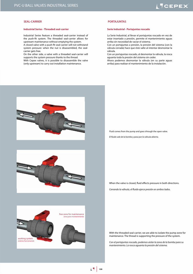
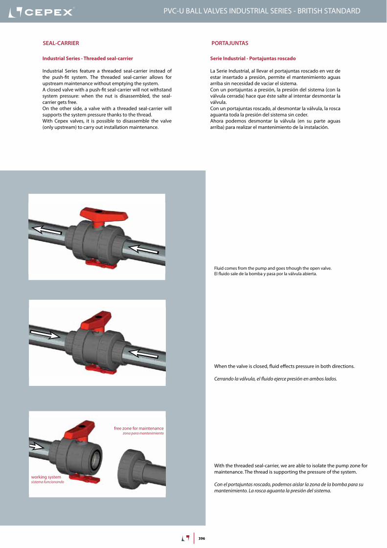
Serie Industrial - Portajuntas roscado
La Serie Industrial, al llevar el portajuntas roscado en vez de estar insertado a presión, permite el mantenimiento aguas arriba sin necesidad de vaciar el sistema.Con un portajuntas a presión, la presión del sistema (con la válvula cerrada) hace que éste salte al intentar desmontar la válvula.Con un portajuntas roscado, al desmontar la válvula, la rosca aguanta toda la presión del sistema sin ceder.Ahora podemos desmontar la válvula (en su parte aguas arriba) para realizar el mantenimiento de la instalación.
Industrial Series - Threaded seal-carrier
Industrial Series feature a threaded seal-carrier instead of the push-fit system. The threaded seal-carrier allows for upstream maintenance without emptying the system.A closed valve with a push-fit seal-carrier will not withstand system pressure: when the nut is disassembled, the seal-carrier gets free.On the other side, a valve with a threaded seal-carrier will supports the system pressure thanks to the thread.With Cepex valves, it is possible to disassemble the valve (only upstream) to carry out installation maintenance.
free zone for maintenancezona para mantenimiento
working systemsistema funcionando
Seal-carrier POrtajUntaS
Fluid comes from the pump and goes trhough the open valve.
el fluido sale de la bomba y pasa por la válvula abierta.
When the valve is closed, fluid effects pressure in both directions.
cerrando la válvula, el fluido ejerce presión en ambos lados.
With the threaded seal-carrier, we are able to isolate the pump zone for maintenance. The thread is supporting the pressure of the system.
con el portajuntas roscado, podemos aislar la zona de la bomba para su mantenimiento. La rosca aguanta la presión del sistema.
PVC-U BALL VALVES INDUSTRIAL SERIES
160
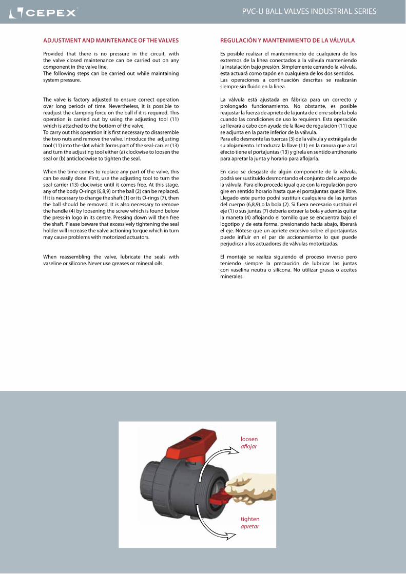
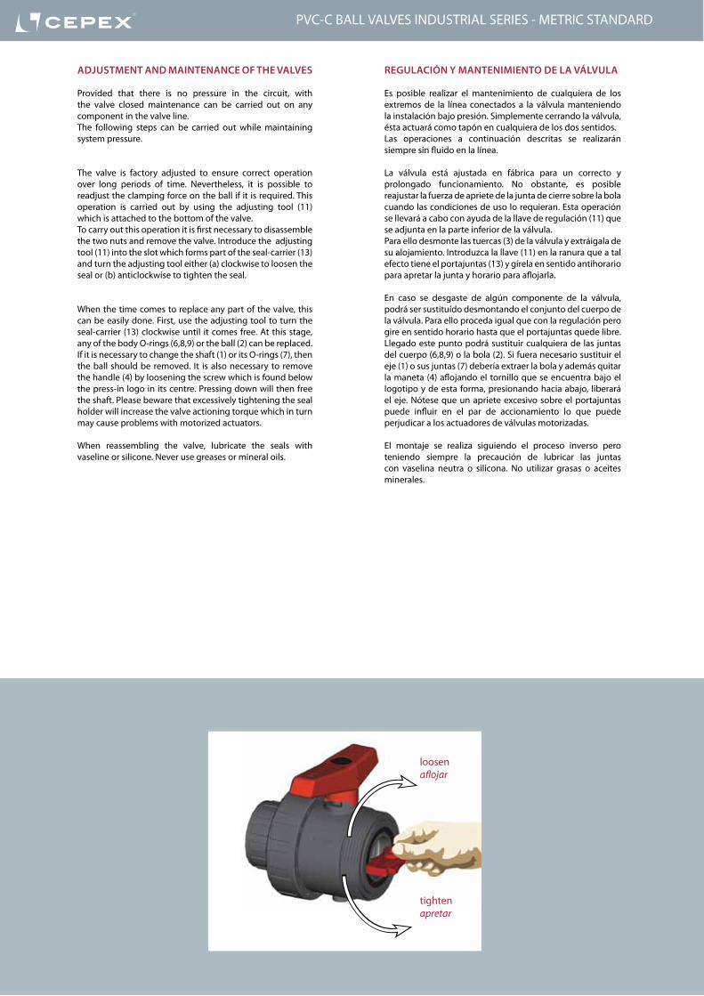
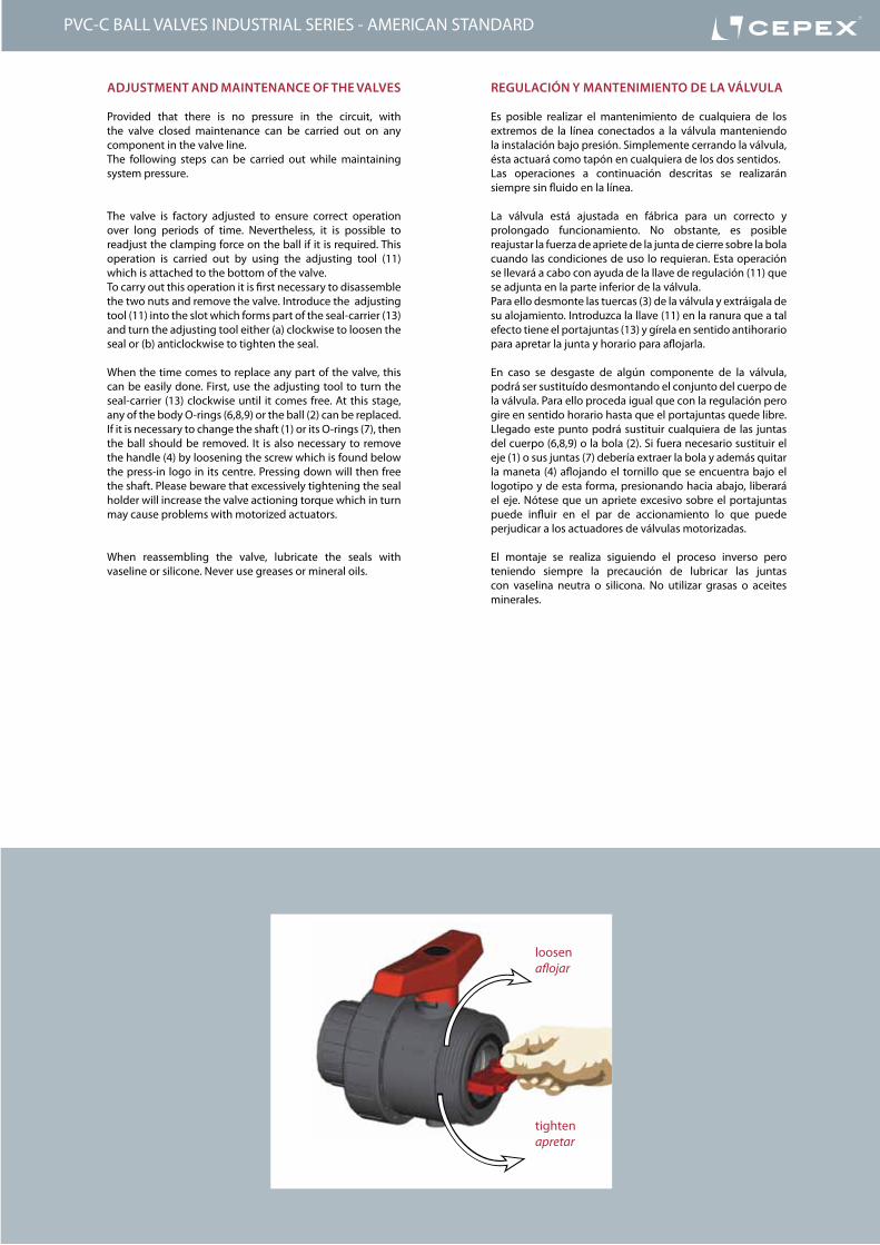
regUlación y ManteniMientO De la válvUla
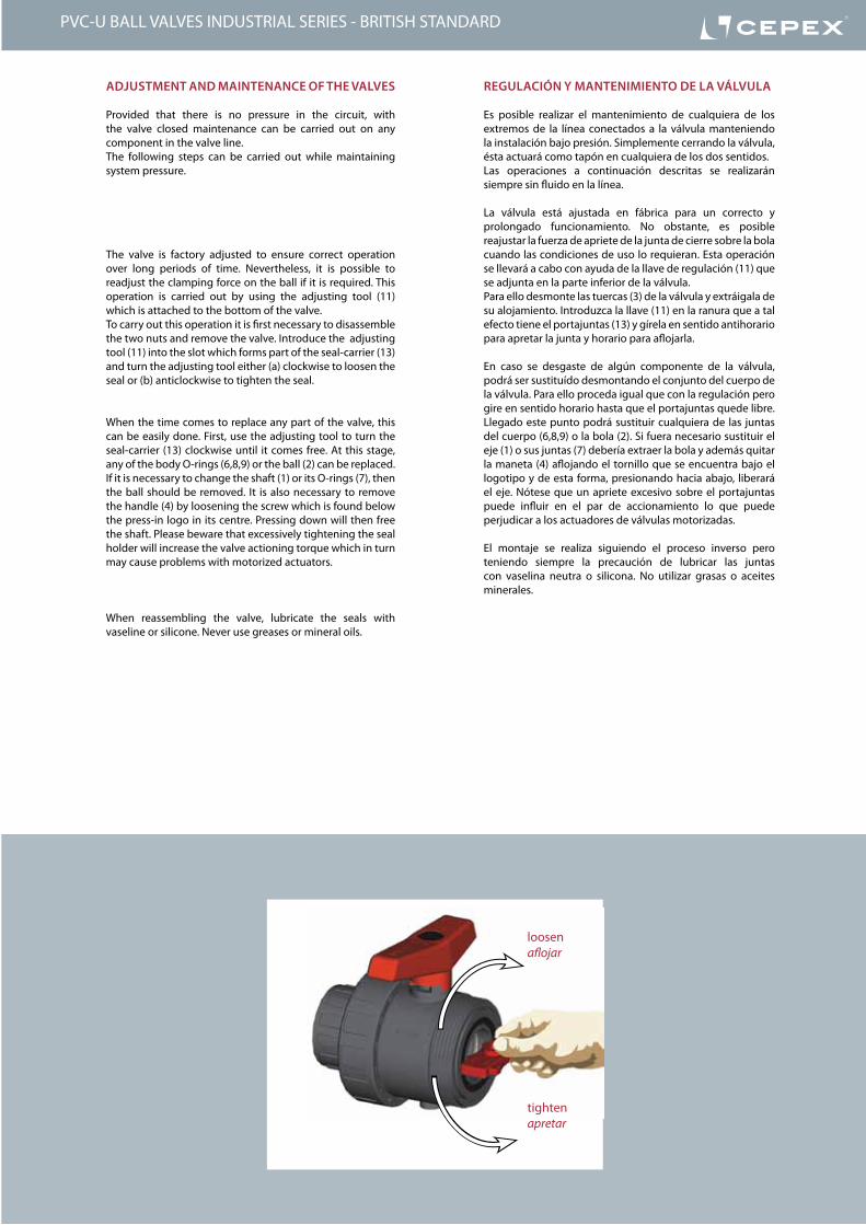
Es posible realizar el mantenimiento de cualquiera de los extremos de la línea conectados a la válvula manteniendo la instalación bajo presión. Simplemente cerrando la válvula, ésta actuará como tapón en cualquiera de los dos sentidos.Las operaciones a continuación descritas se realizarán siempre sin fluido en la línea.
La válvula está ajustada en fábrica para un correcto y prolongado funcionamiento. No obstante, es posible reajustar la fuerza de apriete de la junta de cierre sobre la bola cuando las condiciones de uso lo requieran. Esta operación se llevará a cabo con ayuda de la llave de regulación (11) que se adjunta en la parte inferior de la válvula.Para ello desmonte las tuercas (3) de la válvula y extráigala de su alojamiento. Introduzca la llave (11) en la ranura que a tal efecto tiene el portajuntas (13) y gírela en sentido antihorario para apretar la junta y horario para aflojarla.
En caso se desgaste de algún componente de la válvula, podrá ser sustituído desmontando el conjunto del cuerpo de la válvula. Para ello proceda igual que con la regulación pero gire en sentido horario hasta que el portajuntas quede libre. Llegado este punto podrá sustituir cualquiera de las juntas del cuerpo (6,8,9) o la bola (2). Si fuera necesario sustituir el eje (1) o sus juntas (7) debería extraer la bola y además quitar la maneta (4) aflojando el tornillo que se encuentra bajo el logotipo y de esta forma, presionando hacia abajo, liberará el eje. Nótese que un apriete excesivo sobre el portajuntas puede influir en el par de accionamiento lo que puede perjudicar a los actuadores de válvulas motorizadas.
El montaje se realiza siguiendo el proceso inverso pero teniendo siempre la precaución de lubricar las juntas con vaselina neutra o silicona. No utilizar grasas o aceites minerales.
aDjUStMent anD Maintenance OF the valveS
Provided that there is no pressure in the circuit, with the valve closed maintenance can be carried out on any component in the valve line.The following steps can be carried out while maintaining system pressure.
The valve is factory adjusted to ensure correct operation over long periods of time. Nevertheless, it is possible to readjust the clamping force on the ball if it is required. This operation is carried out by using the adjusting tool (11) which is attached to the bottom of the valve.To carry out this operation it is first necessary to disassemble the two nuts and remove the valve. Introduce the adjusting tool (11) into the slot which forms part of the seal-carrier (13) and turn the adjusting tool either (a) clockwise to loosen the seal or (b) anticlockwise to tighten the seal.
When the time comes to replace any part of the valve, this can be easily done. First, use the adjusting tool to turn the seal-carrier (13) clockwise until it comes free. At this stage, any of the body O-rings (6,8,9) or the ball (2) can be replaced.If it is necessary to change the shaft (1) or its O-rings (7), then the ball should be removed. It is also necessary to remove the handle (4) by loosening the screw which is found below the press-in logo in its centre. Pressing down will then free the shaft. Please beware that excessively tightening the seal holder will increase the valve actioning torque which in turn may cause problems with motorized actuators.
When reassembling the valve, lubricate the seals with vaseline or silicone. Never use greases or mineral oils.
tightenapretar
loosenaflojar
PVC-U BALL VALVES INDUSTRIAL SERIES
161
D DN PN REF. CODE16 10 16 05 73 016 18434
20 15 16 05 73 020 18435
25 20 16 05 73 025 18436
32 25 16 05 73 032 18437
40 32 16 05 73 040 18438
50 40 16 05 73 050 18439
63 50 16 05 73 063 18440
75 65 10 05 73 075 18441
90 80 10 05 73 090 18442
110 100 10 05 73 111 22799
L H E14 84 52
16 84 52
19 108 62
22 124 70
26 142 84
31 167 104
38 198 120
44 232 148
51 269 179
63 359 228
G DN PN REF. CODE⅜” 10 16 05 73 616 18453
½” 15 16 05 73 620 18454
¾” 20 16 05 73 625 18455
1” 25 16 05 73 632 18456
1¼” 32 16 05 73 640 18457
1½” 40 16 05 73 650 18458
2” 50 16 05 73 663 18459
2½” 65 10 05 73 675 18460
3” 80 10 05 73 690 18461
4” 100 10 05 73 711 22800
L H E14 84 52
16 84 52
19 108 62
22 124 70
26 142 84
31 167 104
38 198 120
44 232 148
51 269 179
63 359 228
D DN PN REF. CODE20 15 16 05 69 220 07733
25 20 16 05 69 225 07734
32 25 16 05 69 232 07735
40 32 16 05 69 240 07736
50 40 16 05 69 250 07737
63 50 16 05 69 263 07738
75 65 10 05 69 275 07739
90 80 10 05 69 290 07740
110 80 10 05 69 310 07741
110 100 10 05 69 311 34592
E H K95 130 65
105 150 75
115 160 85
140 180 100
150 200 110
165 230 125
185 290 145
200 310 160
220 350 180
220 418 180
EDD
H
L L
EGG
H
L L
H
DK E
Válvula de bola “Industrial”• Cuerpo en PVC-U• Encolar hembra• Serie métrica• Juntas asiento bola en PTFE• Anillos tóricos en EPDM• Distintivo negro
“Industrial” ball valve• PVC-U body• Female solvent socket• Metric series• Seating joints in PTFE• O-Rings in EPDM• Black dot
UP. 73. SF6 - INDUSTRIAL BALL VALVES
Válvula de bola “Industrial”• Cuerpo en PVC-U• Rosca hembra BSP• Juntas asiento bola en PTFE• Anillos tóricos en EPDM• Distintivo negro
“Industrial” ball valve• PVC-U body• BSP female thread• Seating joints in PTFE• O-Rings in EPDM• Black dot
UP. 73. FT6 - INDUSTRIAL BALL VALVES
Válvula de bola “Industrial”• Cuerpo en PVC-U• Con bridas • Juntas asiento bola en PTFE• Anillos tóricos en EPDM (FPM bajo pedido) • Distintivo negro
“Industrial” ball valve• PVC-U body• With flanges • Seating joints in PTFE• O Rings in EPDM (FPM available on order) • Black dot
UP. 69. FLG6 - INDUSTRIAL BALL VALVES
PVC-U BALL VALVES INDUSTRIAL SERIES
162
D DN PN REF. CODE16 10 16 05 73 016 VI 18444
20 15 16 05 73 020 VI 18445
25 20 16 05 73 025 VI 18670
32 25 16 05 73 032 VI 18446
40 32 16 05 73 040 VI 18447
50 40 16 05 73 050 VI 18448
63 50 16 05 73 063 VI 18449
75 65 10 05 73 075 VI 18450
90 80 10 05 73 090 VI 18451
110 100 10 05 73 111 VI 22801
L H E14 84 52
16 84 52
19 108 62
22 124 70
26 142 84
31 167 104
38 198 120
44 232 148
51 269 179
61 359 228
G DN PN REF. CODE⅜” 10 16 05 73 616 VI 18463
½” 15 16 05 73 620 VI 18464
¾” 20 16 05 73 625 VI 18465
1” 25 16 05 73 632 VI 18466
1¼” 32 16 05 73 640 VI 18467
1½” 40 16 05 73 650 VI 18468
2” 50 16 05 73 663 VI 18469
2½” 65 10 05 73 675 VI 18470
3” 80 10 05 73 690 VI 18471
4” 100 10 05 73 711 VI 22802
L H E14 84 52
16 84 52
19 108 62
22 124 70
26 142 84
31 167 104
38 198 120
44 232 148
51 269 179
61 359 228
EDD
H
L L
EGG
H
L L
Válvula de bola “Industrial”• Cuerpo en PVC-U• Encolar hembra• Serie métrica• Juntas asiento bola en PTFE• Anillos tóricos en FPM• Distintivo verde
“Industrial” ball valve• PVC-U body• Female solvent socket• Metric series• Seating joints in PTFE• O-Rings in FPM• Green dot
UP. 73. SF7 - INDUSTRIAL BALL VALVES
Válvula de bola “Industrial”• Cuerpo en PVC-U• Rosca hembra BSP• Juntas asiento bola en PTFE• Anillos tóricos en FPM• Distintivo verde
“Industrial” ball valve• PVC-U body• BSP female thread• Seating joints in PTFE• O-Rings in FPM• Green dot
UP. 73. FT7 - INDUSTRIAL BALL VALVES
PVC-U BALL VALVES INDUSTRIAL SERIES
392
PVC-U Ball ValVes - inDUsTrial series VálVulas de bola PVC-u - serie iNdusTrial
PVC-U BALL VALVES INDUSTRIAL SERIES - BRITISH STANDARD
Sizes Solvent cement D16 - D110 (DN10-DN100)Threaded ⅜” - 4”
Standards Solvent socket - Metric, British Standard, ASTM, JIS
Threaded - BSP, NPTFlanges: ISOCompression - metric, IPS, CTS
EN ISO 1452, EN ISO 15493, BS 4346-1, ASTM D 2467, JIS K 6743ISO 228-1, ASTM D 2464EN 558-1
Working pressure @ 20ºC (73ºF)
D16 - D63 (⅜” - 2”): PN 16 (240 psi)D75 - D110 (2½” - 4”): PN 10 (150 psi)
Materials O-rings: EPDM / FPM Ball seats: PTFE
Characteristics • “Antiblock” system that avoids ball blockage.• 100% factory tested.• Available in PVC-U or Corzan® PVC-C.• Threaded seal carrier.• It allows the disassembling of the valve while maintaining system pressure.• Union ends for easy installation and removal.• Good mechanical strength.• Resistance to many inorganic chemicals.• Excellent flow characteristics.
• Sistema “Antiblock” que evita el bloqueo de la bola.• Probadas al 100% en fábrica.• Disponibles en PVC-U y Corzan® PVC-C.• Portajuntas roscado.• Permite el desmontaje de la válvula manteniendo la instalación bajo presión.• Manguitos de unión pensados para su fácil instalación y mantenimiento.• Buena resistencia mecánica.• Resistencia a múltiples substancias químicas inorgánicas.• Excelentes características de conducción.
Certifications / regulations Ball valve design regulation - EN ISO 16135
NSF National Sanitation Foundation (USA)Only products bearing the NSF Mark are certifiedNSF 61½” thru 3”ASTM F1970
393
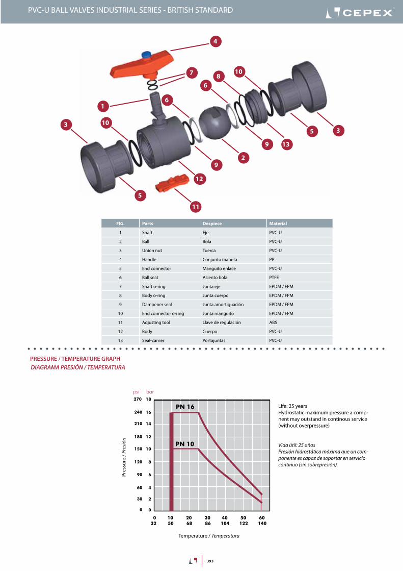
FIG. Parts Despiece Material
1 Shaft Eje PVC-U
2 Ball Bola PVC-U
3 Union nut Tuerca PVC-U
4 Handle Conjunto maneta PP
5 End connector Manguito enlace PVC-U
6 Ball seat Asiento bola PTFE
7 Shaft o-ring Junta eje EPDM / FPM
8 Body o-ring Junta cuerpo EPDM / FPM
9 Dampener seal Junta amortiguación EPDM / FPM
10 End connector o-ring Junta manguito EPDM / FPM
11 Adjusting tool Llave de regulación ABS
12 Body Cuerpo PVC-U
13 Seal-carrier Portajuntas PVC-U
1
2
3
4
9
6
7
9
5
810
3
5
6
12
13
10
11
20 years / water flow20 années / fluide de l�eau20 años / fluido de agua20 anos / caudal de água
18
16
14
12
10
8
6
4
2
0
0 10 20 30 40 50 60
Temperature / Température / Temperatura / Temperatura
Pres
sure
/Pre
ssio
n/ P
resió
n/ P
ress
ão
°C32 50 68 86 104 122 140 °F
barpsi270
240
210
180
150
120
90
60
30
0
DN
15
-3/8
”-½
”
DN
20
-¾
”DN
25
-1”
DN
32
-1¼
”
DN
40
-1½
”DN
50
-2”
DN
65
-2½
”
0,1
10 (l/min)
bar
Kv (l/min , p = 1 bar)
0,01
0,001
1
100 1.000 10.000
DN
80
-3”
DN
100
-4”
2,64 (GPM)26,42 264 2.642
1,50
0,15
0,01
15,0
psi
Flow / Débit / Caudal / Caudal
Pres
sure
loss
/Per
tede
char
ge/
Pérd
ida
deca
rga
/Per
dasd
eca
rga
PN 10
PN 16
PressUre / TeMPeraTUre GraPHdiaGraMa PresiÓN / TeMPeraTura
Pres
sure
/ Pr
esió
n
Temperature / Temperatura
Vida útil: 25 añosPresión hidrostática máxima que un com-ponente es capaz de soportar en servicio continuo (sin sobrepresión)
Life: 25 yearsHydrostatic maximum pressure a comp-nent may outstand in continous service (without overpressure)
PVC-U BALL VALVES INDUSTRIAL SERIES - BRITISH STANDARD
394
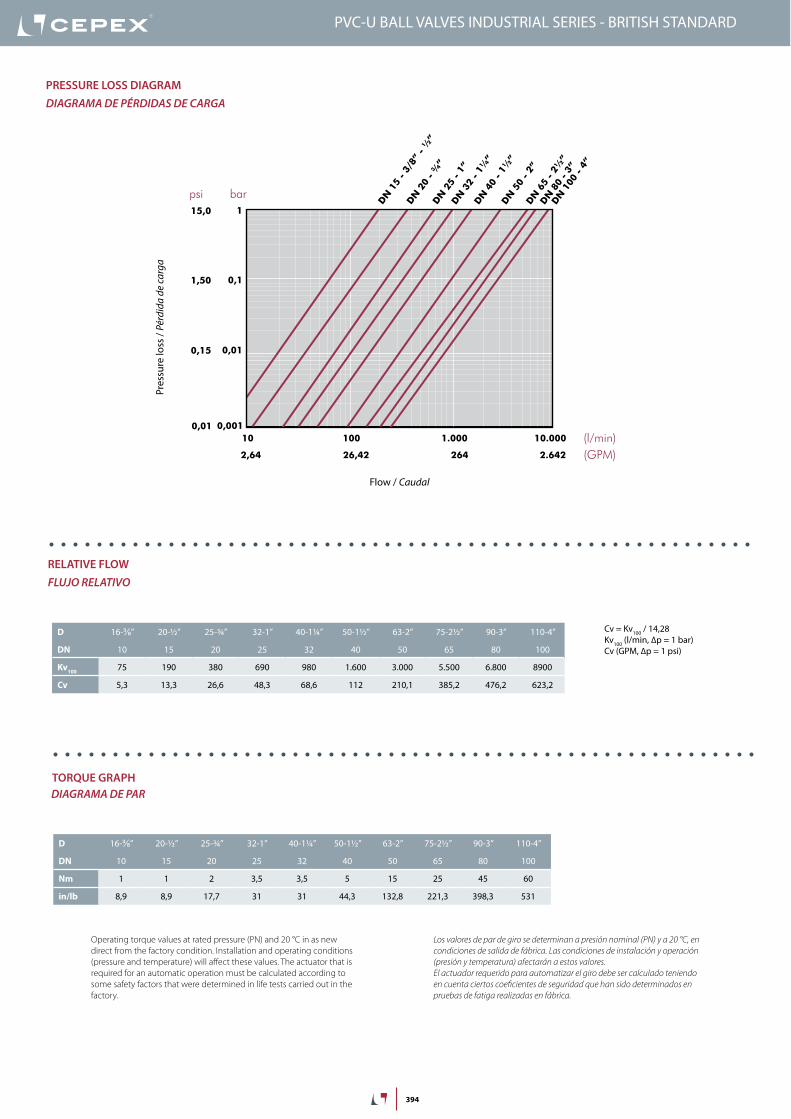
Cv = Kv100 / 14,28Kv100 (l/min, ∆p = 1 bar)Cv (GPM, ∆p = 1 psi)
2,64 26,42 264 2.642
20 years / water flow20 années / fluide de l�eau20 años / fluido de agua20 anos / caudal de água
Temperature / Température / Temperatura / Temperatura
P res
sure
/Pre
ssio
n/ P
resió
n/ P
ress
ão
18
16
14
12
10
8
6
4
2
0
0 10 20 30 40 50 60 70 80 90 °C32 50 68 86 104 122 140 158 176 194 °F
barpsi
DN
15
-3/8
”-½
”
DN
20
-¾
”DN
25
-1”
DN
32
-1¼
”
DN
40
-1½
”DN
50
-2”
DN
65
-2½
”
0,1
10 (l/min)
bar
Kv (l/min , p = 1 bar)
0,01
0,001
1
100 1.000 10.000
DN
80
-3”
DN
100
-4”
(GPM)
1,50
0,15
0,01
15,0
psi
Flow / Débit / Caudal / Caudal
PVC-U
PVC-C
270
240
210
180
150
120
90
60
30
0
Pres
sure
loss
/Per
tede
char
ge/
Pérd
ida
deca
rga
/Per
dasd
eca
rga
PN 10
PN 16
D 16-⅜” 20-½” 25-¾” 32-1” 40-1¼” 50-1½” 63-2” 75-2½” 90-3” 110-4”
DN 10 15 20 25 32 40 50 65 80 100
Kv100 75 190 380 690 980 1.600 3.000 5.500 6.800 8900
Cv 5,3 13,3 26,6 48,3 68,6 112 210,1 385,2 476,2 623,2
PressUre lOss DiaGraMdiaGraMa de PÉrdidas de CarGa
relaTiVe FlOWFluJo relaTiVo
TOrQUe GraPHdiaGraMa de Par
Pres
sure
loss
/ Pé
rdid
a de
carg
a
Flow / Caudal
Operating torque values at rated pressure (PN) and 20 °C in as new direct from the factory condition. Installation and operating conditions (pressure and temperature) will affect these values. The actuator that is required for an automatic operation must be calculated according to some safety factors that were determined in life tests carried out in the factory.
Los valores de par de giro se determinan a presión nominal (PN) y a 20 °C, en condiciones de salida de fábrica. Las condiciones de instalación y operación (presión y temperatura) afectarán a estos valores. El actuador requerido para automatizar el giro debe ser calculado teniendo en cuenta ciertos coeficientes de seguridad que han sido determinados en pruebas de fatiga realizadas en fábrica.
D 16-⅜” 20-½” 25-¾” 32-1” 40-1¼” 50-1½” 63-2” 75-2½” 90-3” 110-4”
DN 10 15 20 25 32 40 50 65 80 100
Nm 1 1 2 3,5 3,5 5 15 25 45 60
in/lb 8,9 8,9 17,7 31 31 44,3 132,8 221,3 398,3 531
PVC-U BALL VALVES INDUSTRIAL SERIES - BRITISH STANDARD

395
insTrUCCiOnes De MOnTaje
Uniones encoladas o roscadasAfloje las tuercas (3) de la válvula y sepárelas de los manguitos (5). Introduzca las tuercas en los tubos y a continuación fije los manguitos en los extremos del tubo. Las uniones encoladas se realizarán con un adhesivo para tubos de PVC-U o PVC-C rígido y no se aplicará presión hasta transcurridas al menos 1 hora por bar. En las uniones roscadas se colocará cinta de PTFE en las roscas macho. A continuación ya podrá colocarse la válvula entre los manguitos y apretar a mano las tuercas sobre la válvula.
asseMBly insTrUCTiOns
Solvent socket or threaded unionsLoosen the valve union nuts (3) and separate these and the end connectors (5) from the valve body. Pass the pipe through the nuts and then place the bushes over the end of the pipe. The socket unions should be guied onto the pipe using a PVC-U or PVC-C adhesive and pressure should not be applied to the system until a drying period of at least 1 hour per bar of working pressure has elapsed. In the case of threaded unions, PTFE tape should be applied to the male threads. The pipes can now be attached to the valve by hand tightening down the nuts.
1
2
3
4
5
PVC-U BALL VALVES INDUSTRIAL SERIES - BRITISH STANDARD
396
Serie Industrial - Portajuntas roscado
La Serie Industrial, al llevar el portajuntas roscado en vez de estar insertado a presión, permite el mantenimiento aguas arriba sin necesidad de vaciar el sistema.Con un portajuntas a presión, la presión del sistema (con la válvula cerrada) hace que éste salte al intentar desmontar la válvula.Con un portajuntas roscado, al desmontar la válvula, la rosca aguanta toda la presión del sistema sin ceder.Ahora podemos desmontar la válvula (en su parte aguas arriba) para realizar el mantenimiento de la instalación.
Industrial Series - Threaded seal-carrier
Industrial Series feature a threaded seal-carrier instead of the push-fit system. The threaded seal-carrier allows for upstream maintenance without emptying the system.A closed valve with a push-fit seal-carrier will not withstand system pressure: when the nut is disassembled, the seal-carrier gets free.On the other side, a valve with a threaded seal-carrier will supports the system pressure thanks to the thread.With Cepex valves, it is possible to disassemble the valve (only upstream) to carry out installation maintenance.
free zone for maintenancezona para mantenimiento
working systemsistema funcionando
seal-Carrier POrTajUnTas
Fluid comes from the pump and goes trhough the open valve.El fluido sale de la bomba y pasa por la válvula abierta.
When the valve is closed, fluid effects pressure in both directions.
Cerrando la válvula, el fluido ejerce presión en ambos lados.
With the threaded seal-carrier, we are able to isolate the pump zone for maintenance. The thread is supporting the pressure of the system.
Con el portajuntas roscado, podemos aislar la zona de la bomba para su mantenimiento. La rosca aguanta la presión del sistema.
PVC-U BALL VALVES INDUSTRIAL SERIES - BRITISH STANDARD
397
reGUlaCión y ManTeniMienTO De la VálVUla
Es posible realizar el mantenimiento de cualquiera de los extremos de la línea conectados a la válvula manteniendo la instalación bajo presión. Simplemente cerrando la válvula, ésta actuará como tapón en cualquiera de los dos sentidos.Las operaciones a continuación descritas se realizarán siempre sin fluido en la línea.
La válvula está ajustada en fábrica para un correcto y prolongado funcionamiento. No obstante, es posible reajustar la fuerza de apriete de la junta de cierre sobre la bola cuando las condiciones de uso lo requieran. Esta operación se llevará a cabo con ayuda de la llave de regulación (11) que se adjunta en la parte inferior de la válvula.Para ello desmonte las tuercas (3) de la válvula y extráigala de su alojamiento. Introduzca la llave (11) en la ranura que a tal efecto tiene el portajuntas (13) y gírela en sentido antihorario para apretar la junta y horario para aflojarla.
En caso se desgaste de algún componente de la válvula, podrá ser sustituído desmontando el conjunto del cuerpo de la válvula. Para ello proceda igual que con la regulación pero gire en sentido horario hasta que el portajuntas quede libre. Llegado este punto podrá sustituir cualquiera de las juntas del cuerpo (6,8,9) o la bola (2). Si fuera necesario sustituir el eje (1) o sus juntas (7) debería extraer la bola y además quitar la maneta (4) aflojando el tornillo que se encuentra bajo el logotipo y de esta forma, presionando hacia abajo, liberará el eje. Nótese que un apriete excesivo sobre el portajuntas puede influir en el par de accionamiento lo que puede perjudicar a los actuadores de válvulas motorizadas.
El montaje se realiza siguiendo el proceso inverso pero teniendo siempre la precaución de lubricar las juntas con vaselina neutra o silicona. No utilizar grasas o aceites minerales.
aDjUsTMenT anD MainTenanCe OF THe ValVes
Provided that there is no pressure in the circuit, with the valve closed maintenance can be carried out on any component in the valve line.The following steps can be carried out while maintaining system pressure.
The valve is factory adjusted to ensure correct operation over long periods of time. Nevertheless, it is possible to readjust the clamping force on the ball if it is required. This operation is carried out by using the adjusting tool (11) which is attached to the bottom of the valve.To carry out this operation it is first necessary to disassemble the two nuts and remove the valve. Introduce the adjusting tool (11) into the slot which forms part of the seal-carrier (13) and turn the adjusting tool either (a) clockwise to loosen the seal or (b) anticlockwise to tighten the seal.
When the time comes to replace any part of the valve, this can be easily done. First, use the adjusting tool to turn the seal-carrier (13) clockwise until it comes free. At this stage, any of the body O-rings (6,8,9) or the ball (2) can be replaced.If it is necessary to change the shaft (1) or its O-rings (7), then the ball should be removed. It is also necessary to remove the handle (4) by loosening the screw which is found below the press-in logo in its centre. Pressing down will then free the shaft. Please beware that excessively tightening the seal holder will increase the valve actioning torque which in turn may cause problems with motorized actuators.
When reassembling the valve, lubricate the seals with vaseline or silicone. Never use greases or mineral oils.
tightenapretar
loosenaflojar
PVC-U BALL VALVES INDUSTRIAL SERIES - BRITISH STANDARD
398
L H E16 84 52
16 84 52
19 108 62
22 124 70
26 142 84
31 167 104
38 198 120
44 232 148
51 269 179
63 359 228
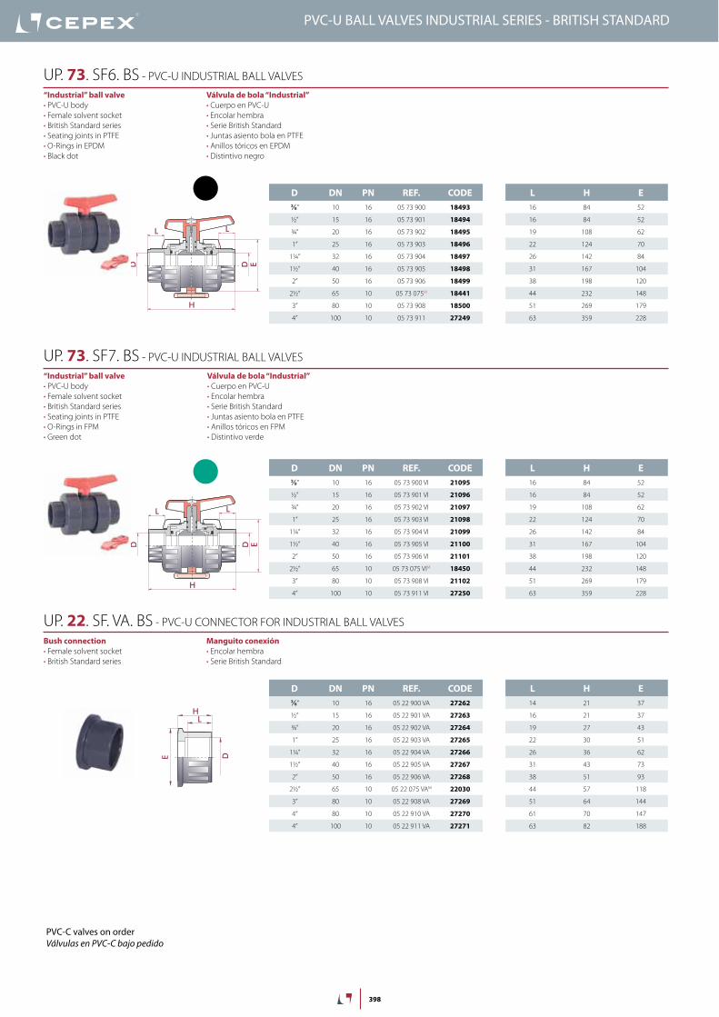
D DN PN REF. CODE⅜” 10 16 05 73 900 18493
½” 15 16 05 73 901 18494
¾” 20 16 05 73 902 18495
1” 25 16 05 73 903 18496
1¼” 32 16 05 73 904 18497
1½” 40 16 05 73 905 18498
2” 50 16 05 73 906 18499
2½” 65 10 05 73 075M 18441
3” 80 10 05 73 908 18500
4” 100 10 05 73 911 27249
EDD
H
L L
Válvula de bola “Industrial”• Cuerpo en PVC-U• Encolar hembra• Serie British Standard• Juntas asiento bola en PTFE• Anillos tóricos en EPDM• Distintivo negro
“Industrial” ball valve• PVC-U body• Female solvent socket• British Standard series• Seating joints in PTFE• O-Rings in EPDM• Black dot
UP. 73. SF6. BS - PVC-U INDUSTRIAL BALL VALVES
L H E16 84 52
16 84 52
19 108 62
22 124 70
26 142 84
31 167 104
38 198 120
44 232 148
51 269 179
63 359 228
D DN PN REF. CODE⅜” 10 16 05 73 900 VI 21095
½” 15 16 05 73 901 VI 21096
¾” 20 16 05 73 902 VI 21097
1” 25 16 05 73 903 VI 21098
1¼” 32 16 05 73 904 VI 21099
1½” 40 16 05 73 905 VI 21100
2” 50 16 05 73 906 VI 21101
2½” 65 10 05 73 075 VIM 18450
3” 80 10 05 73 908 VI 21102
4” 100 10 05 73 911 VI 27250
EDD
H
L L
Válvula de bola “Industrial”• Cuerpo en PVC-U• Encolar hembra• Serie British Standard• Juntas asiento bola en PTFE• Anillos tóricos en FPM• Distintivo verde
“Industrial” ball valve• PVC-U body• Female solvent socket• British Standard series• Seating joints in PTFE• O-Rings in FPM• Green dot
UP. 73. SF7. BS - PVC-U INDUSTRIAL BALL VALVES
L H E14 21 37
16 21 37
19 27 43
22 30 51
26 36 62
31 43 73
38 51 93
44 57 118
51 64 144
61 70 147
63 82 188
D DN PN REF. CODE⅜” 10 16 05 22 900 VA 27262
½” 15 16 05 22 901 VA 27263
¾” 20 16 05 22 902 VA 27264
1” 25 16 05 22 903 VA 27265
1¼” 32 16 05 22 904 VA 27266
1½” 40 16 05 22 905 VA 27267
2” 50 16 05 22 906 VA 27268
2½” 65 10 05 22 075 VAM 22030
3” 80 10 05 22 908 VA 27269
4” 80 10 05 22 910 VA 27270
4” 100 10 05 22 911 VA 27271
H
L
E D
Manguito conexión• Encolar hembra• Serie British Standard
Bush connection• Female solvent socket• British Standard series
UP. 22. SF. VA. BS - PVC-U CONNECTOR FOR INDUSTRIAL BALL VALVES
PVC-C valves on orderVálvulas en PVC-C bajo pedido
PVC-U BALL VALVES INDUSTRIAL SERIES - BRITISH STANDARD
470
PVC-U Ball ValVes - inDUsTrial series VálVulas de bola PVC-u - serie iNdusTrial
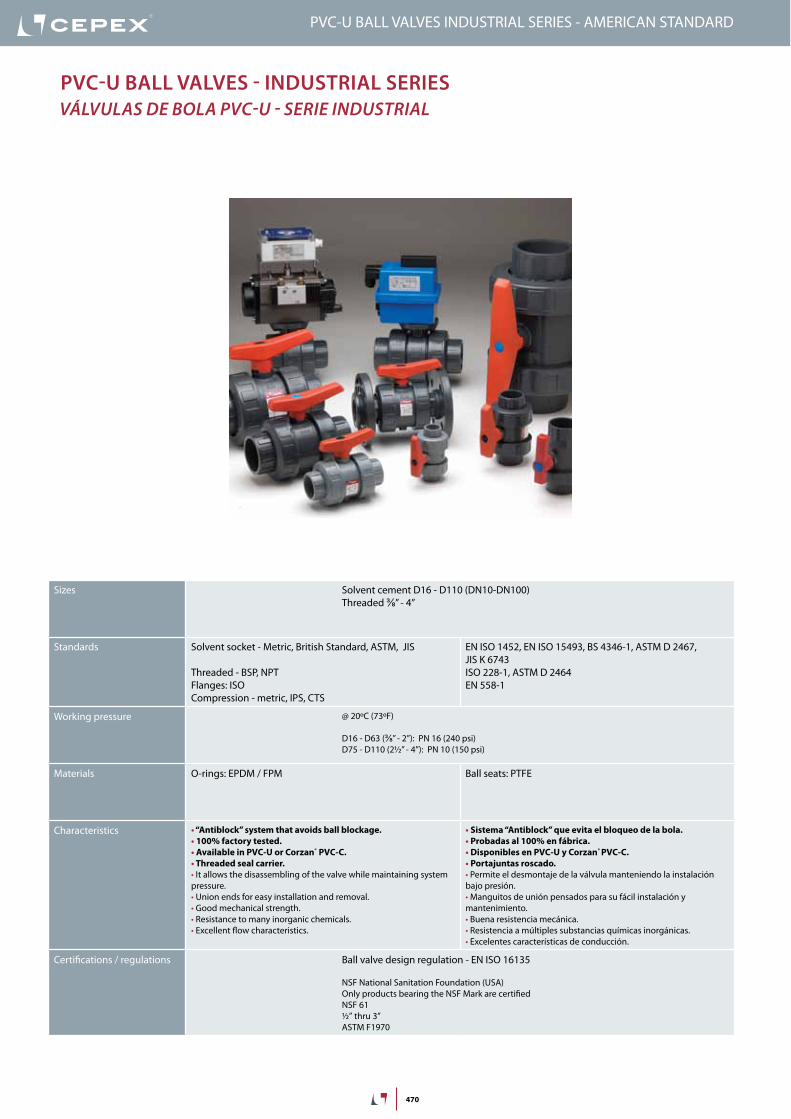
PVC-U BALL VALVES INDUSTRIAL SERIES - AMERICAN STANDARD
Sizes Solvent cement D16 - D110 (DN10-DN100)Threaded ⅜” - 4”
Standards Solvent socket - Metric, British Standard, ASTM, JIS
Threaded - BSP, NPTFlanges: ISOCompression - metric, IPS, CTS
EN ISO 1452, EN ISO 15493, BS 4346-1, ASTM D 2467, JIS K 6743ISO 228-1, ASTM D 2464EN 558-1
Working pressure @ 20ºC (73ºF)
D16 - D63 (⅜” - 2”): PN 16 (240 psi)D75 - D110 (2½” - 4”): PN 10 (150 psi)
Materials O-rings: EPDM / FPM Ball seats: PTFE
Characteristics • “Antiblock” system that avoids ball blockage.• 100% factory tested.• Available in PVC-U or Corzan® PVC-C.• Threaded seal carrier.• It allows the disassembling of the valve while maintaining system pressure.• Union ends for easy installation and removal.• Good mechanical strength.• Resistance to many inorganic chemicals.• Excellent flow characteristics.
• Sistema “Antiblock” que evita el bloqueo de la bola.• Probadas al 100% en fábrica.• Disponibles en PVC-U y Corzan® PVC-C.• Portajuntas roscado.• Permite el desmontaje de la válvula manteniendo la instalación bajo presión.• Manguitos de unión pensados para su fácil instalación y mantenimiento.• Buena resistencia mecánica.• Resistencia a múltiples substancias químicas inorgánicas.• Excelentes características de conducción.
Certifications / regulations Ball valve design regulation - EN ISO 16135
NSF National Sanitation Foundation (USA)Only products bearing the NSF Mark are certifiedNSF 61½” thru 3”ASTM F1970

471
FIG. Parts Despiece Material
1 Shaft Eje PVC-U
2 Ball Bola PVC-U
3 Union nut Tuerca PVC-U
4 Handle Conjunto maneta PP
5 End connector Manguito enlace PVC-U
6 Ball seat Asiento bola PTFE
7 Shaft o-ring Junta eje EPDM / FPM
8 Body o-ring Junta cuerpo EPDM / FPM
9 Dampener seal Junta amortiguación EPDM / FPM
10 End connector o-ring Junta manguito EPDM / FPM
11 Adjusting tool Llave de regulación ABS
12 Body Cuerpo PVC-U
13 Seal-carrier Portajuntas PVC-U
1
2
3
4
9
6
7
9
5
810
3
5
6
12
13
10
11
PVC-U BALL VALVES INDUSTRIAL SERIES - AMERICAN STANDARD
20 years / water flow20 années / fluide de l�eau20 años / fluido de agua20 anos / caudal de água
18
16
14
12
10
8
6
4
2
0
0 10 20 30 40 50 60
Temperature / Température / Temperatura / Temperatura
Pres
sure
/Pre
ssio
n/ P
resió
n/ P
ress
ão
°C32 50 68 86 104 122 140 °F
barpsi270
240
210
180
150
120
90
60
30
0
DN
15
-3/8
”-½
”
DN
20
-¾
”DN
25
-1”
DN
32
-1¼
”
DN
40
-1½
”DN
50
-2”
DN
65
-2½
”
0,1
10 (l/min)
bar
Kv (l/min , p = 1 bar)
0,01
0,001
1
100 1.000 10.000
DN
80
-3”
DN
100
-4”
2,64 (GPM)26,42 264 2.642
1,50
0,15
0,01
15,0
psi
Flow / Débit / Caudal / Caudal
Pres
sure
loss
/Per
tede
char
ge/
Pérd
ida
deca
rga
/Per
dasd
eca
rga
PN 10
PN 16
PressUre / TeMPeraTUre GraPHdiaGraMa PresiÓN / TeMPeraTura
Pres
sure
/ Pr
esió
n
Temperature / Temperatura
Vida útil: 25 añosPresión hidrostática máxima que un com-ponente es capaz de soportar en servicio continuo (sin sobrepresión)
Life: 25 yearsHydrostatic maximum pressure a comp-nent may outstand in continous service (without overpressure)
472
Cv = Kv100 / 14,28Kv100 (l/min, ∆p = 1 bar)Cv (GPM, ∆p = 1 psi)
2,64 26,42 264 2.642
20 years / water flow20 années / fluide de l�eau20 años / fluido de agua20 anos / caudal de água
Temperature / Température / Temperatura / Temperatura
P res
sure
/Pre
ssio
n/ P
resió
n/ P
ress
ão
18
16
14
12
10
8
6
4
2
0
0 10 20 30 40 50 60 70 80 90 °C32 50 68 86 104 122 140 158 176 194 °F
barpsi
DN
15
-3/8
”-½
”
DN
20
-¾
”DN
25
-1”
DN
32
-1¼
”
DN
40
-1½
”DN
50
-2”
DN
65
-2½
”
0,1
10 (l/min)
bar
Kv (l/min , p = 1 bar)
0,01
0,001
1
100 1.000 10.000
DN
80
-3”
DN
100
-4”
(GPM)
1,50
0,15
0,01
15,0
psi
Flow / Débit / Caudal / Caudal
PVC-U
PVC-C
270
240
210
180
150
120
90
60
30
0
Pres
sure
loss
/Per
tede
char
ge/
Pérd
ida
deca
rga
/Per
dasd
eca
rga
PN 10
PN 16
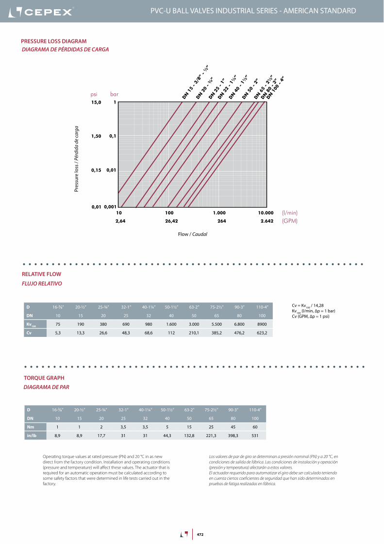
D 16-⅜” 20-½” 25-¾” 32-1” 40-1¼” 50-1½” 63-2” 75-2½” 90-3” 110-4”
DN 10 15 20 25 32 40 50 65 80 100
Kv100 75 190 380 690 980 1.600 3.000 5.500 6.800 8900
Cv 5,3 13,3 26,6 48,3 68,6 112 210,1 385,2 476,2 623,2
PressUre lOss DiaGraMdiaGraMa de PÉrdidas de CarGa
relaTiVe FlOW
FluJo relaTiVo
TOrQUe GraPH
diaGraMa de Par
Pres
sure
loss
/ Pé
rdid
a de
carg
a
Flow / Caudal
PVC-U BALL VALVES INDUSTRIAL SERIES - AMERICAN STANDARD
Operating torque values at rated pressure (PN) and 20 °C in as new direct from the factory condition. Installation and operating conditions (pressure and temperature) will affect these values. The actuator that is required for an automatic operation must be calculated according to some safety factors that were determined in life tests carried out in the factory.
Los valores de par de giro se determinan a presión nominal (PN) y a 20 °C, en condiciones de salida de fábrica. Las condiciones de instalación y operación (presión y temperatura) afectarán a estos valores. El actuador requerido para automatizar el giro debe ser calculado teniendo en cuenta ciertos coeficientes de seguridad que han sido determinados en pruebas de fatiga realizadas en fábrica.
D 16-⅜” 20-½” 25-¾” 32-1” 40-1¼” 50-1½” 63-2” 75-2½” 90-3” 110-4”
DN 10 15 20 25 32 40 50 65 80 100
Nm 1 1 2 3,5 3,5 5 15 25 45 60
in/lb 8,9 8,9 17,7 31 31 44,3 132,8 221,3 398,3 531
473
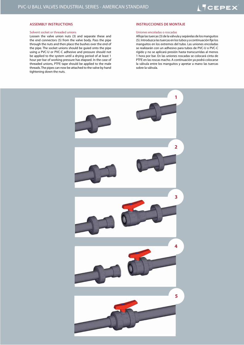
insTrUCCiOnes De MOnTaje
Uniones encoladas o roscadasAfloje las tuercas (3) de la válvula y sepárelas de los manguitos (5). Introduzca las tuercas en los tubos y a continuación fije los manguitos en los extremos del tubo. Las uniones encoladas se realizarán con un adhesivo para tubos de PVC-U o PVC-C rígido y no se aplicará presión hasta transcurridas al menos 1 hora por bar. En las uniones roscadas se colocará cinta de PTFE en las roscas macho. A continuación ya podrá colocarse la válvula entre los manguitos y apretar a mano las tuercas sobre la válvula.
asseMBly insTrUCTiOns
Solvent socket or threaded unionsLoosen the valve union nuts (3) and separate these and the end connectors (5) from the valve body. Pass the pipe through the nuts and then place the bushes over the end of the pipe. The socket unions should be guied onto the pipe using a PVC-U or PVC-C adhesive and pressure should not be applied to the system until a drying period of at least 1 hour per bar of working pressure has elapsed. In the case of threaded unions, PTFE tape should be applied to the male threads. The pipes can now be attached to the valve by hand tightening down the nuts.
1
2
3
4
5
PVC-U BALL VALVES INDUSTRIAL SERIES - AMERICAN STANDARD
474
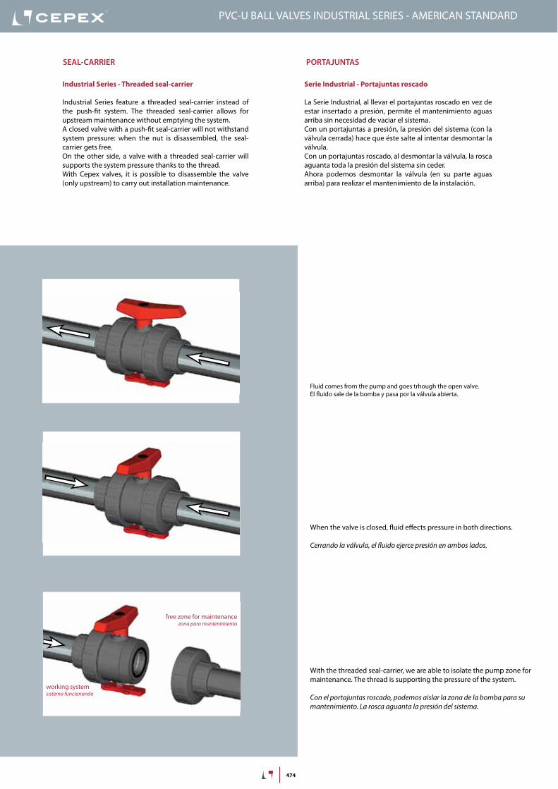
Serie Industrial - Portajuntas roscado
La Serie Industrial, al llevar el portajuntas roscado en vez de estar insertado a presión, permite el mantenimiento aguas arriba sin necesidad de vaciar el sistema.Con un portajuntas a presión, la presión del sistema (con la válvula cerrada) hace que éste salte al intentar desmontar la válvula.Con un portajuntas roscado, al desmontar la válvula, la rosca aguanta toda la presión del sistema sin ceder.Ahora podemos desmontar la válvula (en su parte aguas arriba) para realizar el mantenimiento de la instalación.
Industrial Series - Threaded seal-carrier
Industrial Series feature a threaded seal-carrier instead of the push-fit system. The threaded seal-carrier allows for upstream maintenance without emptying the system.A closed valve with a push-fit seal-carrier will not withstand system pressure: when the nut is disassembled, the seal-carrier gets free.On the other side, a valve with a threaded seal-carrier will supports the system pressure thanks to the thread.With Cepex valves, it is possible to disassemble the valve (only upstream) to carry out installation maintenance.
free zone for maintenancezona para mantenimiento
working systemsistema funcionando
seal-Carrier POrTajUnTas
Fluid comes from the pump and goes trhough the open valve.El fluido sale de la bomba y pasa por la válvula abierta.
When the valve is closed, fluid effects pressure in both directions.
Cerrando la válvula, el fluido ejerce presión en ambos lados.
With the threaded seal-carrier, we are able to isolate the pump zone for maintenance. The thread is supporting the pressure of the system.
Con el portajuntas roscado, podemos aislar la zona de la bomba para su mantenimiento. La rosca aguanta la presión del sistema.
PVC-U BALL VALVES INDUSTRIAL SERIES - AMERICAN STANDARD
475
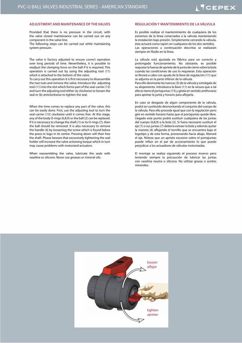
reGUlaCión y ManTeniMienTO De la VálVUla
Es posible realizar el mantenimiento de cualquiera de los extremos de la línea conectados a la válvula manteniendo la instalación bajo presión. Simplemente cerrando la válvula, ésta actuará como tapón en cualquiera de los dos sentidos.Las operaciones a continuación descritas se realizarán siempre sin fluido en la línea.
La válvula está ajustada en fábrica para un correcto y prolongado funcionamiento. No obstante, es posible reajustar la fuerza de apriete de la junta de cierre sobre la bola cuando las condiciones de uso lo requieran. Esta operación se llevará a cabo con ayuda de la llave de regulación (11) que se adjunta en la parte inferior de la válvula.Para ello desmonte las tuercas (3) de la válvula y extráigala de su alojamiento. Introduzca la llave (11) en la ranura que a tal efecto tiene el portajuntas (13) y gírela en sentido antihorario para apretar la junta y horario para aflojarla.
En caso se desgaste de algún componente de la válvula, podrá ser sustituído desmontando el conjunto del cuerpo de la válvula. Para ello proceda igual que con la regulación pero gire en sentido horario hasta que el portajuntas quede libre. Llegado este punto podrá sustituir cualquiera de las juntas del cuerpo (6,8,9) o la bola (2). Si fuera necesario sustituir el eje (1) o sus juntas (7) debería extraer la bola y además quitar la maneta (4) aflojando el tornillo que se encuentra bajo el logotipo y de esta forma, presionando hacia abajo, liberará el eje. Nótese que un apriete excesivo sobre el portajuntas puede influir en el par de accionamiento lo que puede perjudicar a los actuadores de válvulas motorizadas.
El montaje se realiza siguiendo el proceso inverso pero teniendo siempre la precaución de lubricar las juntas con vaselina neutra o silicona. No utilizar grasas o aceites minerales.
aDjUsTMenT anD MainTenanCe OF THe ValVes
Provided that there is no pressure in the circuit, with the valve closed maintenance can be carried out on any component in the valve line.The following steps can be carried out while maintaining system pressure.
The valve is factory adjusted to ensure correct operation over long periods of time. Nevertheless, it is possible to readjust the clamping force on the ball if it is required. This operation is carried out by using the adjusting tool (11) which is attached to the bottom of the valve.To carry out this operation it is first necessary to disassemble the two nuts and remove the valve. Introduce the adjusting tool (11) into the slot which forms part of the seal-carrier (13) and turn the adjusting tool either (a) clockwise to loosen the seal or (b) anticlockwise to tighten the seal.
When the time comes to replace any part of the valve, this can be easily done. First, use the adjusting tool to turn the seal-carrier (13) clockwise until it comes free. At this stage, any of the body O-rings (6,8,9) or the ball (2) can be replaced.If it is necessary to change the shaft (1) or its O-rings (7), then the ball should be removed. It is also necessary to remove the handle (4) by loosening the screw which is found below the press-in logo in its centre. Pressing down will then free the shaft. Please beware that excessively tightening the seal holder will increase the valve actioning torque which in turn may cause problems with motorized actuators.
When reassembling the valve, lubricate the seals with vaseline or silicone. Never use greases or mineral oils.
tightenapretar
loosenaflojar
PVC-U BALL VALVES INDUSTRIAL SERIES - AMERICAN STANDARD
476
D DN PN REF. CODE⅜” 15 16 05 73 900 MA 21124
½” 15 16 05 73 901 MA 21125
¾” 20 16 05 73 902 MA 21126
1” 25 16 05 73 903 MA 21127
1¼” 32 16 05 73 904 MA 21128
1½” 40 16 05 73 905 MA 21129
2” 50 16 05 73 906 MA 21130
2½” 65 10 05 73 907 MA 21131
3” 80 10 05 73 908 MA 21132
4” 80 10 05 73 910 MA 21133
4” 100 10 05 73 911 MA 22064
L H E14 84 52
16 84 52
19 108 62
22 124 70
26 142 84
31 167 104
38 198 120
44 232 148
51 269 179
63 359 228
63 359 228
G DN PN REF. CODE⅜” 15 16 05 73 800 21134
½” 15 16 05 73 801 21135
¾” 20 16 05 73 802 21136
1” 25 16 05 73 803 21137
1¼” 32 16 05 73 804 21138
1½” 40 16 05 73 805 21139
2” 50 16 05 73 806 21140
2½” 65 10 05 73 807 21141
3” 80 10 05 73 808 21142
4” 100 10 05 73 811 22063
L H E14 84 52
16 84 52
19 108 62
22 124 70
26 142 84
31 167 104
38 198 120
44 232 148
51 269 179
63 359 228
EDD
H
L L
EGG
H
L L
Válvula de bola “Industrial”• Cuerpo en PVC-U• Encolar hembra• Serie ASTM• Juntas asiento bola en PTFE• Anillos tóricos en EPDM• Distintivo negro
“Industrial” ball valve• PVC-U body• Female solvent socket• ASTM series• Seating joints in PTFE• O-Rings in EPDM• Black dot
UP. 73. SF6. MA - PVC-U INDUSTRIAL BALL VALVE
Válvula de bola “Industrial”• Cuerpo en PVC-U• Rosca hembra NPT• Juntas asiento bola en PTFE• Anillos tóricos en EPDM• Distintivo negro
“Industrial” ball valve• PVC-U body• NPT female thread• Seating joints in PTFE• O-Rings in EPDM• Black dot
UP. 73. FT6. MA - PVC-U INDUSTRIAL BALL VALVE
PVC-U BALL VALVES INDUSTRIAL SERIES - AMERICAN STANDARD
477
D DN PN REF. CODE⅜” 15 16 05 73 900 AV 21144
½” 15 16 05 73 901 AV 21145
¾” 20 16 05 73 902 AV 21146
1” 25 16 05 73 903 AV 21147
1¼” 32 16 05 73 904 AV 21148
1½” 40 16 05 73 905 AV 21149
2” 50 16 05 73 906 AV 21150
2½” 65 10 05 73 907 AV 21131VIT
3” 80 10 05 73 908 AV 21132VIT
4” 100 10 05 73 911 AV 22064VIT
L H E14 84 52
16 84 52
19 108 62
22 124 70
26 142 84
31 167 104
38 198 120
44 232 148
51 269 179
61 359 228
G DN PN REF. CODE⅜” 15 16 05 73 800 VI 21154
½” 15 16 05 73 801 VI 21155
¾” 20 16 05 73 802 VI 21156
1” 25 16 05 73 803 VI 21157
1¼” 32 16 05 73 804 VI 21158
1½” 40 16 05 73 805 VI 21159
2” 50 16 05 73 806 VI 21160
2½” 65 10 05 73 807 VI 21161
3” 80 10 05 73 808 VI 21162
4” 100 10 05 73 811 VI 22063VIT
L H E14 84 52
16 84 52
19 108 62
22 124 70
26 142 84
31 167 104
38 198 120
44 232 148
51 269 179
61 359 228
EDD
H
L L
EGG
H
L L
Válvula de bola “Industrial”• Cuerpo en PVC-U• Encolar hembra• Serie ASTM• Juntas asiento bola en PTFE• Anillos tóricos en FPM• Distintivo verde
“Industrial” ball valve• PVC-U body• Female solvent socket• ASTM series• Seating joints in PTFE• O-Rings in FPM• Green dot
UP. 73. SF7.MA - PVC-U INDUSTRIAL BALL VALVE
Válvula de bola “Industrial”• Cuerpo en PVC-U• Rosca hembra NPT• Juntas asiento bola en PTFE• Anillos tóricos en FPM• Distintivo verde
“Industrial” ball valve• PVC-U body• NPT female thread• Seating joints in PTFE• O-Rings in FPM• Green dot
UP. 73. FT7.MA - PVC-U INDUSTRIAL BALL VALVE
PVC-U BALL VALVES INDUSTRIAL SERIES - AMERICAN STANDARD
567
PVC-C Ball ValVes - inDUsTrial series VálVulas de bola PVC-C - serie iNdusTrial
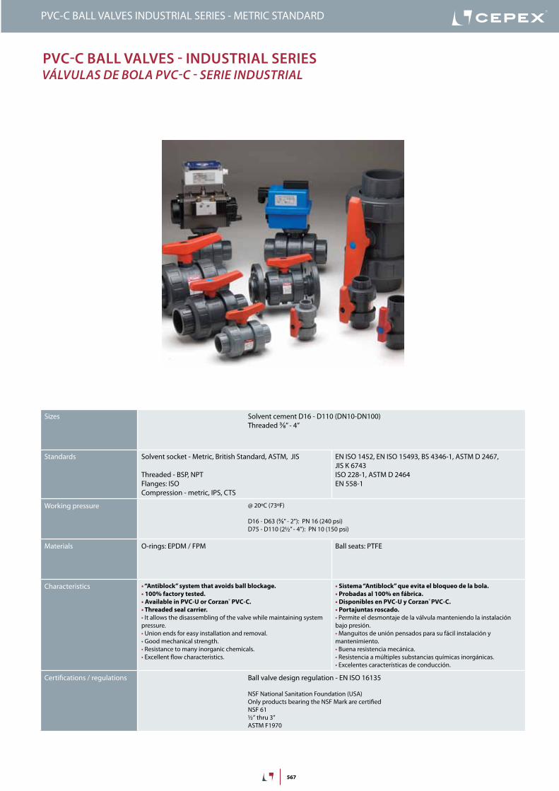
PVC-C BALL VALVES INDUSTRIAL SERIES - METRIC STANDARD
Sizes Solvent cement D16 - D110 (DN10-DN100)Threaded ⅜” - 4”
Standards Solvent socket - Metric, British Standard, ASTM, JIS
Threaded - BSP, NPTFlanges: ISOCompression - metric, IPS, CTS
EN ISO 1452, EN ISO 15493, BS 4346-1, ASTM D 2467, JIS K 6743ISO 228-1, ASTM D 2464EN 558-1
Working pressure @ 20ºC (73ºF)
D16 - D63 (⅜” - 2”): PN 16 (240 psi)D75 - D110 (2½” - 4”): PN 10 (150 psi)
Materials O-rings: EPDM / FPM Ball seats: PTFE
Characteristics • “Antiblock” system that avoids ball blockage.• 100% factory tested.• Available in PVC-U or Corzan® PVC-C.• Threaded seal carrier.• It allows the disassembling of the valve while maintaining system pressure.• Union ends for easy installation and removal.• Good mechanical strength.• Resistance to many inorganic chemicals.• Excellent flow characteristics.
• Sistema “Antiblock” que evita el bloqueo de la bola.• Probadas al 100% en fábrica.• Disponibles en PVC-U y Corzan® PVC-C.• Portajuntas roscado.• Permite el desmontaje de la válvula manteniendo la instalación bajo presión.• Manguitos de unión pensados para su fácil instalación y mantenimiento.• Buena resistencia mecánica.• Resistencia a múltiples substancias químicas inorgánicas.• Excelentes características de conducción.
Certifications / regulations Ball valve design regulation - EN ISO 16135
NSF National Sanitation Foundation (USA)Only products bearing the NSF Mark are certifiedNSF 61½” thru 3”ASTM F1970
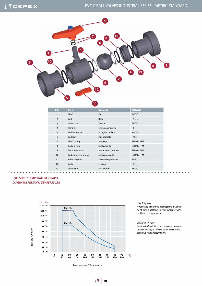
568
FIG. Parts Despiece Material
1 Shaft Eje PVC-C
2 Ball Bola PVC-C
3 Union nut Tuerca PVC-C
4 Handle Conjunto maneta PP
5 End connector Manguito enlace PVC-C
6 Ball seat Asiento bola PTFE
7 Shaft o-ring Junta eje EPDM / FPM
8 Body o-ring Junta cuerpo EPDM / FPM
9 Dampener seal Junta amortiguación EPDM / FPM
10 End connector o-ring Junta manguito EPDM / FPM
11 Adjusting tool Llave de regulación ABS
12 Body Cuerpo PVC-C
13 Seal-carrier Portajuntas PVC-C
1
2
3
4
9
6
7
9
5
810
3
5
6
12
13
10
11
PressUre / TeMPeraTUre GraPHdiaGraMa PresiÓN / TeMPeraTura
PN 16
PN 10
Pres
sure
/ Pr
esió
n
Temperature / Temperatura
Vida útil: 25 añosPresión hidrostática máxima que un com-ponente es capaz de soportar en servicio continuo (sin sobrepresión)
Life: 25 yearsHydrostatic maximum pressure a comp-nent may outstand in continous service (without overpressure)
PVC-C BALL VALVES INDUSTRIAL SERIES - METRIC STANDARD
569
PVC-C BALL VALVES INDUSTRIAL SERIES - METRIC STANDARD
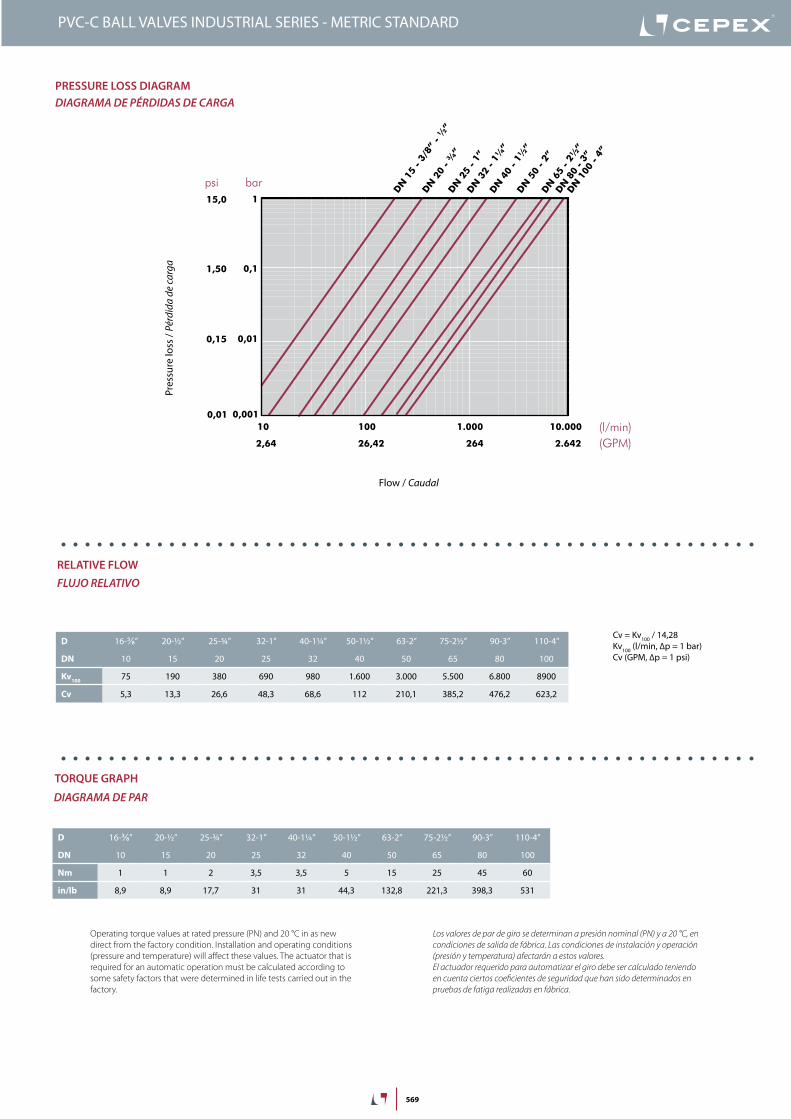
Cv = Kv100 / 14,28Kv100 (l/min, ∆p = 1 bar)Cv (GPM, ∆p = 1 psi)
20 years / water flow20 années / fluide de l�eau20 años / fluido de agua20 anos / caudal de água
18
16
14
12
10
8
6
4
2
0
0 10 20 30 40 50 60
Temperature / Température / Temperatura / Temperatura
Pres
sure
/Pre
ssio
n/ P
resió
n/ P
ress
ão
°C32 50 68 86 104 122 140 °F
barpsi270
240
210
180
150
120
90
60
30
0
DN
15
-3/8
”-½
”
DN
20
-¾
”DN
25
-1”
DN
32
-1¼
”
DN
40
-1½
”DN
50
-2”
DN
65
-2½
”
0,1
10 (l/min)
bar
Kv (l/min , p = 1 bar)
0,01
0,001
1
100 1.000 10.000
DN
80
-3”
DN
100
-4”
2,64 (GPM)26,42 264 2.642
1,50
0,15
0,01
15,0
psi
Flow / Débit / Caudal / Caudal
Pres
sure
loss
/Per
tede
char
ge/
Pérd
ida
deca
rga
/Per
dasd
eca
rga
PN 10
PN 16
D 16-⅜” 20-½” 25-¾” 32-1” 40-1¼” 50-1½” 63-2” 75-2½” 90-3” 110-4”
DN 10 15 20 25 32 40 50 65 80 100
Kv100 75 190 380 690 980 1.600 3.000 5.500 6.800 8900
Cv 5,3 13,3 26,6 48,3 68,6 112 210,1 385,2 476,2 623,2
PressUre lOss DiaGraMdiaGraMa de PÉrdidas de CarGa
relaTiVe FlOWFluJo relaTiVo
TOrQUe GraPH
diaGraMa de Par
Pres
sure
loss
/ Pé
rdid
a de
carg
a
Flow / Caudal
Operating torque values at rated pressure (PN) and 20 °C in as new direct from the factory condition. Installation and operating conditions (pressure and temperature) will affect these values. The actuator that is required for an automatic operation must be calculated according to some safety factors that were determined in life tests carried out in the factory.
Los valores de par de giro se determinan a presión nominal (PN) y a 20 °C, en condiciones de salida de fábrica. Las condiciones de instalación y operación (presión y temperatura) afectarán a estos valores. El actuador requerido para automatizar el giro debe ser calculado teniendo en cuenta ciertos coeficientes de seguridad que han sido determinados en pruebas de fatiga realizadas en fábrica.
D 16-⅜” 20-½” 25-¾” 32-1” 40-1¼” 50-1½” 63-2” 75-2½” 90-3” 110-4”
DN 10 15 20 25 32 40 50 65 80 100
Nm 1 1 2 3,5 3,5 5 15 25 45 60
in/lb 8,9 8,9 17,7 31 31 44,3 132,8 221,3 398,3 531
570
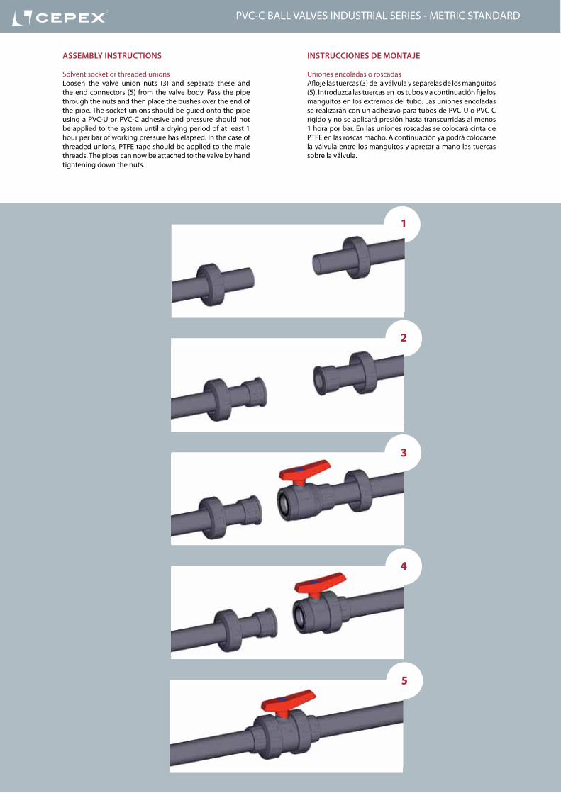
insTrUCCiOnes De MOnTaje
Uniones encoladas o roscadasAfloje las tuercas (3) de la válvula y sepárelas de los manguitos (5). Introduzca las tuercas en los tubos y a continuación fije los manguitos en los extremos del tubo. Las uniones encoladas se realizarán con un adhesivo para tubos de PVC-U o PVC-C rígido y no se aplicará presión hasta transcurridas al menos 1 hora por bar. En las uniones roscadas se colocará cinta de PTFE en las roscas macho. A continuación ya podrá colocarse la válvula entre los manguitos y apretar a mano las tuercas sobre la válvula.
asseMBly insTrUCTiOns
Solvent socket or threaded unionsLoosen the valve union nuts (3) and separate these and the end connectors (5) from the valve body. Pass the pipe through the nuts and then place the bushes over the end of the pipe. The socket unions should be guied onto the pipe using a PVC-U or PVC-C adhesive and pressure should not be applied to the system until a drying period of at least 1 hour per bar of working pressure has elapsed. In the case of threaded unions, PTFE tape should be applied to the male threads. The pipes can now be attached to the valve by hand tightening down the nuts.
1
2
3
4
5
PVC-C BALL VALVES INDUSTRIAL SERIES - METRIC STANDARD

571
Serie Industrial - Portajuntas roscado
La Serie Industrial, al llevar el portajuntas roscado en vez de estar insertado a presión, permite el mantenimiento aguas arriba sin necesidad de vaciar el sistema.Con un portajuntas a presión, la presión del sistema (con la válvula cerrada) hace que éste salte al intentar desmontar la válvula.Con un portajuntas roscado, al desmontar la válvula, la rosca aguanta toda la presión del sistema sin ceder.Ahora podemos desmontar la válvula (en su parte aguas arriba) para realizar el mantenimiento de la instalación.
Industrial Series - Threaded seal-carrier
Industrial Series feature a threaded seal-carrier instead of the push-fit system. The threaded seal-carrier allows for upstream maintenance without emptying the system.A closed valve with a push-fit seal-carrier will not withstand system pressure: when the nut is disassembled, the seal-carrier gets free.On the other side, a valve with a threaded seal-carrier will supports the system pressure thanks to the thread.With Cepex valves, it is possible to disassemble the valve (only upstream) to carry out installation maintenance.
free zone for maintenancezona para mantenimiento
working systemsistema funcionando
seal-Carrier POrTajUnTas
Fluid comes from the pump and goes trhough the open valve.El fluido sale de la bomba y pasa por la válvula abierta.
When the valve is closed, fluid effects pressure in both directions.
Cerrando la válvula, el fluido ejerce presión en ambos lados.
With the threaded seal-carrier, we are able to isolate the pump zone for maintenance. The thread is supporting the pressure of the system.
Con el portajuntas roscado, podemos aislar la zona de la bomba para su mantenimiento. La rosca aguanta la presión del sistema.
PVC-C BALL VALVES INDUSTRIAL SERIES - METRIC STANDARD
572
reGUlaCión y ManTeniMienTO De la VálVUla
Es posible realizar el mantenimiento de cualquiera de los extremos de la línea conectados a la válvula manteniendo la instalación bajo presión. Simplemente cerrando la válvula, ésta actuará como tapón en cualquiera de los dos sentidos.Las operaciones a continuación descritas se realizarán siempre sin fluido en la línea.
La válvula está ajustada en fábrica para un correcto y prolongado funcionamiento. No obstante, es posible reajustar la fuerza de apriete de la junta de cierre sobre la bola cuando las condiciones de uso lo requieran. Esta operación se llevará a cabo con ayuda de la llave de regulación (11) que se adjunta en la parte inferior de la válvula.Para ello desmonte las tuercas (3) de la válvula y extráigala de su alojamiento. Introduzca la llave (11) en la ranura que a tal efecto tiene el portajuntas (13) y gírela en sentido antihorario para apretar la junta y horario para aflojarla.
En caso se desgaste de algún componente de la válvula, podrá ser sustituído desmontando el conjunto del cuerpo de la válvula. Para ello proceda igual que con la regulación pero gire en sentido horario hasta que el portajuntas quede libre. Llegado este punto podrá sustituir cualquiera de las juntas del cuerpo (6,8,9) o la bola (2). Si fuera necesario sustituir el eje (1) o sus juntas (7) debería extraer la bola y además quitar la maneta (4) aflojando el tornillo que se encuentra bajo el logotipo y de esta forma, presionando hacia abajo, liberará el eje. Nótese que un apriete excesivo sobre el portajuntas puede influir en el par de accionamiento lo que puede perjudicar a los actuadores de válvulas motorizadas.
El montaje se realiza siguiendo el proceso inverso pero teniendo siempre la precaución de lubricar las juntas con vaselina neutra o silicona. No utilizar grasas o aceites minerales.
aDjUsTMenT anD MainTenanCe OF THe ValVes
Provided that there is no pressure in the circuit, with the valve closed maintenance can be carried out on any component in the valve line.The following steps can be carried out while maintaining system pressure.
The valve is factory adjusted to ensure correct operation over long periods of time. Nevertheless, it is possible to readjust the clamping force on the ball if it is required. This operation is carried out by using the adjusting tool (11) which is attached to the bottom of the valve.To carry out this operation it is first necessary to disassemble the two nuts and remove the valve. Introduce the adjusting tool (11) into the slot which forms part of the seal-carrier (13) and turn the adjusting tool either (a) clockwise to loosen the seal or (b) anticlockwise to tighten the seal.
When the time comes to replace any part of the valve, this can be easily done. First, use the adjusting tool to turn the seal-carrier (13) clockwise until it comes free. At this stage, any of the body O-rings (6,8,9) or the ball (2) can be replaced.If it is necessary to change the shaft (1) or its O-rings (7), then the ball should be removed. It is also necessary to remove the handle (4) by loosening the screw which is found below the press-in logo in its centre. Pressing down will then free the shaft. Please beware that excessively tightening the seal holder will increase the valve actioning torque which in turn may cause problems with motorized actuators.
When reassembling the valve, lubricate the seals with vaseline or silicone. Never use greases or mineral oils.
tightenapretar
loosenaflojar
PVC-C BALL VALVES INDUSTRIAL SERIES - METRIC STANDARD

573
G DN PN REF. CODE⅜” 10 16 35 73 616 22814
½” 15 16 35 73 620 22815
¾” 20 16 35 73 625 22816
1” 25 16 35 73 632 22817
1¼” 32 16 35 73 640 22818
1½” 40 16 35 73 650 22819
2” 50 16 35 73 663 22820
2½” 65 10 35 73 675 22821
3” 80 10 35 73 690 22822
4” 100 10 35 73 711 26445
L H E14 84 52
16 84 52
19 108 62
22 124 70
26 142 84
31 167 104
38 198 120
44 232 148
51 269 179
63 359 228
D DN PN REF. CODE16 10 16 35 73 016 VI 22824
20 15 16 35 73 020 VI 22825
25 20 16 35 73 025 VI 22826
32 25 16 35 73 032 VI 22827
40 32 16 35 73 040 VI 22828
50 40 16 35 73 050 VI 22829
63 50 16 35 73 063 VI 22830
75 65 10 35 73 075 VI 22831
90 80 10 35 73 090 VI 22832
110 100 10 35 73 111 VI 26446
G DN PN REF. CODE⅜” 10 16 35 73 616 VI 22834
½” 15 16 35 73 620 VI 22835
¾” 20 16 35 73 625 VI 22836
1” 25 16 35 73 632 VI 22837
1¼” 32 16 35 73 640 VI 22838
1½” 40 16 35 73 650 VI 22839
2” 50 16 35 73 663 VI 22840
2½” 65 10 35 73 675 VI 22841
3” 80 10 35 73 690 VI 22842
4” 100 10 35 73 711 VI 26447
L H E14 84 52
16 84 52
19 108 62
22 124 70
26 142 84
31 167 104
38 198 120
44 232 148
51 269 179
63 359 228
EDD
H
L L
EGG
H
L L
EGG
H
L L
Válvula de bola “Industrial”• Cuerpo en Corzan® PVC-C• Rosca hembra BSP• Juntas asiento bola en PTFE• Anillos tóricos en EPDM• Distintivo negro
“Industrial” ball valve• Corzan® PVC-C body• BSP female thread• Seating joints in PTFE• O Rings in EPDM• Black dot
CP. 73. FT6 - PVC-C INDUSTRIAL BALL VALVE
Válvula de bola “Industrial”• Cuerpo en Corzan® PVC-C• Encolar hembra• Serie métrica• Juntas asiento bola en PTFE• Anillos tóricos en FPM• Distintivo verde
“Industrial” ball valve• Corzan® PVC-C body• Female solvent socket• Metric series• Seating joints in PTFE• O-Rings in FPM• Green dot
CP. 73. SF7 - PVC-C INDUSTRIAL BALL VALVE
Válvula de bola “Industrial”• Cuerpo en Corzan® PVC-C• Rosca hembra BSP• Serie métrica• Juntas asiento bola en PTFE• Anillos tóricos en FPM• Distintivo verde
“Industrial” ball valve• Corzan® PVC-C body• BSP female thread• Seating joints in PTFE• O-Rings in FPM• Green dot
CP. 73. FT7 - PVC-C INDUSTRIAL BALL VALVE
L H E14 84 52
16 84 52
19 108 62
22 124 70
26 142 84
31 167 104
38 198 120
44 232 148
51 269 179
63 359 228
PVC-C BALL VALVES INDUSTRIAL SERIES - METRIC STANDARD
G DN PN REF. CODE16 10 16 35 73 016 22804
20 15 16 35 73 020 22805
25 20 16 35 73 025 22806
32 25 16 35 73 032 22807
40 32 16 35 73 040 22808
50 40 16 35 73 050 22809
63 50 16 35 73 063 22810
75 65 10 35 73 075 22811
90 80 10 35 73 090 22812
110 100 10 35 73 111 26444
L H E14 84 52
16 84 52
19 108 62
22 124 70
26 142 84
31 167 104
38 198 120
44 232 148
51 269 179
63 359 228
EGG
H
L L
Válvula de bola “Industrial”• Cuerpo en Corzan® PVC-C• Rosca hembra BSP• Juntas asiento bola en PTFE• Anillos tóricos en EPDM• Distintivo negro
“Industrial” ball valve• Corzan® PVC-C body• BSP female thread• Seating joints in PTFE• O Rings in EPDM• Black dot
CP. 73. FT6 - PVC-C INDUSTRIAL BALL VALVE
600
PVC-C Ball ValVes - inDUsTrial series VálVulas de bola PVC-C - serie iNdusTrial
PVC-C BALL VALVES INDUSTRIAL SERIES - AMERICAN STANDARD
Sizes Solvent cement D16 - D110 (DN10-DN100)Threaded ⅜” - 4”
Standards Solvent socket - Metric, British Standard, ASTM, JIS
Threaded - BSP, NPTFlanges: ISOCompression - metric, IPS, CTS
EN ISO 1452, EN ISO 15493, BS 4346-1, ASTM D 2467, JIS K 6743ISO 228-1, ASTM D 2464EN 558-1
Working pressure @ 20ºC (73ºF)
D16 - D63 (⅜” - 2”): PN 16 (240 psi)D75 - D110 (2½” - 4”): PN 10 (150 psi)
Materials O-rings: EPDM / FPM Ball seats: PTFE
Characteristics • “Antiblock” system that avoids ball blockage.• 100% factory tested.• Available in PVC-U or Corzan® PVC-C.• Threaded seal carrier.• It allows the disassembling of the valve while maintaining system pressure.• Union ends for easy installation and removal.• Good mechanical strength.• Resistance to many inorganic chemicals.• Excellent flow characteristics.
• Sistema “Antiblock” que evita el bloqueo de la bola.• Probadas al 100% en fábrica.• Disponibles en PVC-U y Corzan® PVC-C.• Portajuntas roscado.• Permite el desmontaje de la válvula manteniendo la instalación bajo presión.• Manguitos de unión pensados para su fácil instalación y mantenimiento.• Buena resistencia mecánica.• Resistencia a múltiples substancias químicas inorgánicas.• Excelentes características de conducción.
Certifications / regulations Ball valve design regulation - EN ISO 16135
NSF National Sanitation Foundation (USA)Only products bearing the NSF Mark are certifiedNSF 61½” thru 3”ASTM F1970

601
PVC-C BALL VALVES INDUSTRIAL SERIES - AMERICAN STANDARD
FIG. Parts Despiece Material
1 Shaft Eje PVC-C
2 Ball Bola PVC-C
3 Union nut Tuerca PVC-C
4 Handle Conjunto maneta PP
5 End connector Manguito enlace PVC-C
6 Ball seat Asiento bola PTFE
7 Shaft o-ring Junta eje EPDM / FPM
8 Body o-ring Junta cuerpo EPDM / FPM
9 Dampener seal Junta amortiguación EPDM / FPM
10 End connector o-ring Junta manguito EPDM / FPM
11 Adjusting tool Llave de regulación ABS
12 Body Cuerpo PVC-C
13 Seal-carrier Portajuntas PVC-C
1
2
3
4
9
6
7
9
5
810
3
5
6
12
13
10
11
PressUre / TeMPeraTUre GraPHdiaGraMa PresiÓN / TeMPeraTura
PN 16
PN 10
Pres
sure
/ Pr
esió
n
Temperature / Temperatura
Vida útil: 25 añosPresión hidrostática máxima que un com-ponente es capaz de soportar en servicio continuo (sin sobrepresión)
Life: 25 yearsHydrostatic maximum pressure a comp-nent may outstand in continous service (without overpressure)
602
PVC-C BALL VALVES INDUSTRIAL SERIES - AMERICAN STANDARD
Cv = Kv100 / 14,28Kv100 (l/min, ∆p = 1 bar)Cv (GPM, ∆p = 1 psi)
20 years / water flow20 années / fluide de l�eau20 años / fluido de agua20 anos / caudal de água
18
16
14
12
10
8
6
4
2
0
0 10 20 30 40 50 60
Temperature / Température / Temperatura / Temperatura
Pres
sure
/Pre
ssio
n/ P
resió
n/ P
ress
ão
°C32 50 68 86 104 122 140 °F
barpsi270
240
210
180
150
120
90
60
30
0
DN
15
-3/8
”-½
”
DN
20
-¾
”DN
25
-1”
DN
32
-1¼
”
DN
40
-1½
”DN
50
-2”
DN
65
-2½
”
0,1
10 (l/min)
bar
Kv (l/min , p = 1 bar)
0,01
0,001
1
100 1.000 10.000
DN
80
-3”
DN
100
-4”
2,64 (GPM)26,42 264 2.642
1,50
0,15
0,01
15,0
psi
Flow / Débit / Caudal / Caudal
Pres
sure
loss
/Per
tede
char
ge/
Pérd
ida
deca
rga
/Per
dasd
eca
rga
PN 10
PN 16
D 16-⅜” 20-½” 25-¾” 32-1” 40-1¼” 50-1½” 63-2” 75-2½” 90-3” 110-4”
DN 10 15 20 25 32 40 50 65 80 100
Kv100 75 190 380 690 980 1.600 3.000 5.500 6.800 8900
Cv 5,3 13,3 26,6 48,3 68,6 112 210,1 385,2 476,2 623,2
PressUre lOss DiaGraMdiaGraMa de PÉrdidas de CarGa
relaTiVe FlOWFlUjO relaTiVO
TOrQUe GraPH
diaGraMa de Par
Pres
sure
loss
/ Pé
rdid
a de
carg
a
Flow / Caudal
Operating torque values at rated pressure (PN) and 20 °C in as new direct from the factory condition. Installation and operating conditions (pressure and temperature) will affect these values. The actuator that is required for an automatic operation must be calculated according to some safety factors that were determined in life tests carried out in the factory.
Los valores de par de giro se determinan a presión nominal (PN) y a 20 °C, en condiciones de salida de fábrica. Las condiciones de instalación y operación (presión y temperatura) afectarán a estos valores. El actuador requerido para automatizar el giro debe ser calculado teniendo en cuenta ciertos coeficientes de seguridad que han sido determinados en pruebas de fatiga realizadas en fábrica.
D 16-⅜” 20-½” 25-¾” 32-1” 40-1¼” 50-1½” 63-2” 75-2½” 90-3” 110-4”
DN 10 15 20 25 32 40 50 65 80 100
Nm 1 1 2 3,5 3,5 5 15 25 45 60
in/lb 8,9 8,9 17,7 31 31 44,3 132,8 221,3 398,3 531
603
PVC-C BALL VALVES INDUSTRIAL SERIES - AMERICAN STANDARD
insTrUCCiOnes De MOnTaje
Uniones encoladas o roscadasAfloje las tuercas (3) de la válvula y sepárelas de los manguitos (5). Introduzca las tuercas en los tubos y a continuación fije los manguitos en los extremos del tubo. Las uniones encoladas se realizarán con un adhesivo para tubos de PVC-U o PVC-C rígido y no se aplicará presión hasta transcurridas al menos 1 hora por bar. En las uniones roscadas se colocará cinta de PTFE en las roscas macho. A continuación ya podrá colocarse la válvula entre los manguitos y apretar a mano las tuercas sobre la válvula.
asseMBly insTrUCTiOns
Solvent socket or threaded unionsLoosen the valve union nuts (3) and separate these and the end connectors (5) from the valve body. Pass the pipe through the nuts and then place the bushes over the end of the pipe. The socket unions should be guied onto the pipe using a PVC-U or PVC-C adhesive and pressure should not be applied to the system until a drying period of at least 1 hour per bar of working pressure has elapsed. In the case of threaded unions, PTFE tape should be applied to the male threads. The pipes can now be attached to the valve by hand tightening down the nuts.
1
2
3
4
5

604
Serie Industrial - Portajuntas roscado
La Serie Industrial, al llevar el portajuntas roscado en vez de estar insertado a presión, permite el mantenimiento aguas arriba sin necesidad de vaciar el sistema.Con un portajuntas a presión, la presión del sistema (con la válvula cerrada) hace que éste salte al intentar desmontar la válvula.Con un portajuntas roscado, al desmontar la válvula, la rosca aguanta toda la presión del sistema sin ceder.Ahora podemos desmontar la válvula (en su parte aguas arriba) para realizar el mantenimiento de la instalación.
Industrial Series - Threaded seal-carrier
Industrial Series feature a threaded seal-carrier instead of the push-fit system. The threaded seal-carrier allows for upstream maintenance without emptying the system.A closed valve with a push-fit seal-carrier will not withstand system pressure: when the nut is disassembled, the seal-carrier gets free.On the other side, a valve with a threaded seal-carrier will supports the system pressure thanks to the thread.With Cepex valves, it is possible to disassemble the valve (only upstream) to carry out installation maintenance.
free zone for maintenancezona para mantenimiento
working systemsistema funcionando
seal-Carrier POrTajUnTas
Fluid comes from the pump and goes trhough the open valve.El fluido sale de la bomba y pasa por la válvula abierta.
When the valve is closed, fluid effects pressure in both directions.
Cerrando la válvula, el fluido ejerce presión en ambos lados.
With the threaded seal-carrier, we are able to isolate the pump zone for maintenance. The thread is supporting the pressure of the system.
Con el portajuntas roscado, podemos aislar la zona de la bomba para su mantenimiento. La rosca aguanta la presión del sistema.
PVC-C BALL VALVES INDUSTRIAL SERIES - AMERICAN STANDARD
605
reGUlaCión y ManTeniMienTO De la VálVUla
Es posible realizar el mantenimiento de cualquiera de los extremos de la línea conectados a la válvula manteniendo la instalación bajo presión. Simplemente cerrando la válvula, ésta actuará como tapón en cualquiera de los dos sentidos.Las operaciones a continuación descritas se realizarán siempre sin fluido en la línea.
La válvula está ajustada en fábrica para un correcto y prolongado funcionamiento. No obstante, es posible reajustar la fuerza de apriete de la junta de cierre sobre la bola cuando las condiciones de uso lo requieran. Esta operación se llevará a cabo con ayuda de la llave de regulación (11) que se adjunta en la parte inferior de la válvula.Para ello desmonte las tuercas (3) de la válvula y extráigala de su alojamiento. Introduzca la llave (11) en la ranura que a tal efecto tiene el portajuntas (13) y gírela en sentido antihorario para apretar la junta y horario para aflojarla.
En caso se desgaste de algún componente de la válvula, podrá ser sustituído desmontando el conjunto del cuerpo de la válvula. Para ello proceda igual que con la regulación pero gire en sentido horario hasta que el portajuntas quede libre. Llegado este punto podrá sustituir cualquiera de las juntas del cuerpo (6,8,9) o la bola (2). Si fuera necesario sustituir el eje (1) o sus juntas (7) debería extraer la bola y además quitar la maneta (4) aflojando el tornillo que se encuentra bajo el logotipo y de esta forma, presionando hacia abajo, liberará el eje. Nótese que un apriete excesivo sobre el portajuntas puede influir en el par de accionamiento lo que puede perjudicar a los actuadores de válvulas motorizadas.
El montaje se realiza siguiendo el proceso inverso pero teniendo siempre la precaución de lubricar las juntas con vaselina neutra o silicona. No utilizar grasas o aceites minerales.
aDjUsTMenT anD MainTenanCe OF THe ValVes
Provided that there is no pressure in the circuit, with the valve closed maintenance can be carried out on any component in the valve line.The following steps can be carried out while maintaining system pressure.
The valve is factory adjusted to ensure correct operation over long periods of time. Nevertheless, it is possible to readjust the clamping force on the ball if it is required. This operation is carried out by using the adjusting tool (11) which is attached to the bottom of the valve.To carry out this operation it is first necessary to disassemble the two nuts and remove the valve. Introduce the adjusting tool (11) into the slot which forms part of the seal-carrier (13) and turn the adjusting tool either (a) clockwise to loosen the seal or (b) anticlockwise to tighten the seal.
When the time comes to replace any part of the valve, this can be easily done. First, use the adjusting tool to turn the seal-carrier (13) clockwise until it comes free. At this stage, any of the body O-rings (6,8,9) or the ball (2) can be replaced.If it is necessary to change the shaft (1) or its O-rings (7), then the ball should be removed. It is also necessary to remove the handle (4) by loosening the screw which is found below the press-in logo in its centre. Pressing down will then free the shaft. Please beware that excessively tightening the seal holder will increase the valve actioning torque which in turn may cause problems with motorized actuators.
When reassembling the valve, lubricate the seals with vaseline or silicone. Never use greases or mineral oils.
tightenapretar
loosenaflojar
PVC-C BALL VALVES INDUSTRIAL SERIES - AMERICAN STANDARD

606
G DN PN REF. CODE½” 15 16 35 73 801 D 22230
¾” 20 16 35 73 802 D 22231
1” 25 16 35 73 803 D 22232
1¼” 32 16 35 73 804 D 22233
1½” 40 16 35 73 805 D 22234
2” 50 16 35 73 806 D 22235
2½” 65 10 35 73 807 22248
3” 80 10 35 73 808 22249
4” 100 10 35 73 811 22250
L H E16 84 52
19 108 62
22 124 70
26 142 84
31 167 104
38 198 120
44 232 148
51 269 179
63 359 228
EGG
H
L L
Válvula de bola “Industrial”• Cuerpo en Corzan® PVC-C• Rosca hembra NPT• Juntas asiento bola en PTFE• Anillos tóricos en EPDM• Distintivo negro
“Industrial” ball valve• Corzan® PVC-C body• NPT female thread• Seating joints in PTFE• O Rings in EPDM• Black dot
CP. 73. FT6. MA - PVC-C INDUSTRIAL BALL VALVE
D DN PN REF. CODE½” 15 16 35 73 901 MA 25216
¾” 20 16 35 73 902 MA 25217
1” 25 16 35 73 903 MA 25218
1¼” 32 16 35 73 904 MA 25219
1½” 40 16 35 73 905 MA 25220
2” 50 16 35 73 906 MA 25221
2½” 65 10 35 73 907 MA 22245
3” 80 10 35 73 908 MA 22246
4” 100 10 35 73 911 MA 22247
L H E16 84 52
19 108 62
22 124 70
26 142 84
31 167 104
38 198 120
44 232 148
51 269 179
63 359 228
EDD
H
L L
Válvula de bola “Industrial”• Cuerpo en Corzan® PVC-C• Encolar hembra• Serie ASTM• Juntas asiento bola en PTFE• Anillos tóricos en EPDM• Distintivo negro
“Industrial” ball valve• Corzan® PVC-C body• Female solvent socket• ASTM series• Seating joints in PTFE• O-Rings in EPDM• Black dot
CP. 73. SF6. MA - PVC-C INDUSTRIAL BALL VALVE
PVC-C BALL VALVES INDUSTRIAL SERIES - AMERICAN STANDARD
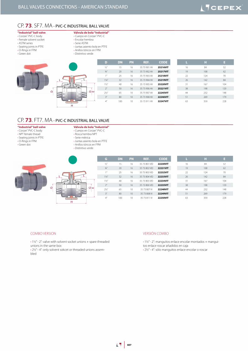
607
D DN PN REF. CODE½” 15 16 35 73 901 AV 25216VIT
¾” 20 16 35 73 902 AV 25217VIT
1” 25 16 35 73 903 AV 25218VIT
1¼” 32 16 35 73 904 AV 25219VIT
1½” 40 16 35 73 905 AV 25220VIT
2” 50 16 35 73 906 AV 25221VIT
2½” 65 10 35 73 907 AV 22245VIT
3” 80 10 35 73 908 AV 22246VIT
4” 100 10 35 73 911 AV 22247VIT
G DN PN REF. CODE½” 15 16 35 73 801 VID 22230VIT
¾” 20 16 35 73 802 VID 22231VIT
1” 25 16 35 73 803 VID 22232VIT
1¼” 32 16 35 73 804 VID 22233VIT
1½” 40 16 35 73 805 VID 22234VIT
2” 50 16 35 73 806 VID 22235VIT
2½” 65 10 35 73 807 VI 22248VIT
3” 80 10 35 73 808 VI 22249VIT
4” 100 10 35 73 811 VI 22250VIT
L H E16 84 52
19 108 62
22 124 70
26 142 84
31 167 104
38 198 120
44 232 148
51 269 179
63 359 228
EDD
H
L L
EGG
H
L L
Válvula de bola “Industrial”• Cuerpo en Corzan® PVC-C• Encolar hembra• Serie ASTM• Juntas asiento bola en PTFE• Anillos tóricos en FPM• Distintivo verde
“Industrial” ball valve• Corzan® PVC-C body• Female solvent socket• ASTM series• Seating joints in PTFE• O-Rings in FPM• Green dot
CP. 73. SF7. MA - PVC-C INDUSTRIAL BALL VALVE
Válvula de bola “Industrial”• Cuerpo en Corzan® PVC-C• Rosca hembra NPT• Serie métrica• Juntas asiento bola en PTFE• Anillos tóricos en FPM• Distintivo verde
“Industrial” ball valve• Corzan® PVC-C body• NPT female thread• Seating joints in PTFE• O-Rings in FPM• Green dot
CP. 73. FT7. MA - PVC-C INDUSTRIAL BALL VALVE
L H E16 84 52
19 108 62
22 124 70
26 142 84
31 167 104
38 198 120
44 232 148
51 269 179
63 359 228
VERSIÓN COMBO
• 1½” - 2”: manguitos enlace encolar montados + mangui-tos enlace roscar añadidos en caja• 2½” - 4”: sólo manguitos enlace encolar o roscar
COMBO VERSION
• 1½” - 2”: valve with solvent socket unions + spare threadedunions in the same box• 2½” - 4”: only solvent sokcet or threaded unions assem-bled
BALL VALVES CONNECTIONS - AMERICAN STANDARD


![CSF - 04 Valvulas Retencao [Modo de compatibilidad]cepex.com/pricelists/csf/CSF - 04 Valvulas Retencao_PT.pdf · Montagem entre flanges na válvula de clapeta Fácil instalação,](https://img.pdfslide.us/doc/110x75/5c08b23b09d3f29f288c532f/csf-04-valvulas-retencao-modo-de-compatibilidadcepexcompricelistscsfcsf.jpg)


![Pvc-U Ball valveS - [StD] SerieS - cepex.com · con vaselina neutra o silicona. No utilizar grasas o aceites minerales. aDjUStMent anD Maintenance OF the valveS Provided that there](https://img.pdfslide.us/doc/110x75/5c0d5df909d3f2cb6c8d88b2/pvc-u-ball-valves-std-series-cepexcom-con-vaselina-neutra-o-silicona.jpg)