Embed Size (px)
Citation preview
PVC Soil& waste ranges
marleypd.co.uk
32 | MARLEY PVC Soil & Waste
PVCu Soil and Waste Systems
Marley Plumbing & Drainage offer a comprehensive
range of soil and waste systems. Available with
a variety of jointing methods, Marley products
are manufactured to UK and European standards
and are designed for use on commercial and
residential projects.
PVCu soil & waste systems are available with
push-fit or solvent weld joints, offering a choice
of installation methods.
Innovation & Expertise
Product specification information
This guide contains design and installation information for Marley PVCu soil & waste drainage systems. All documentation can be downloaded from marleypd.co.uk
Key
ABS = Acrylonitrile butadiene styrene
PVCu = Poly vinyl chloride un-plasticised
PP = Polypropylene
BS EN ISO 9001:2008BS EN ISO 14001:2004
4 Marley soil & waste systems
6 Solvent waste – PVCu
8 Solvent waste – ABS
10 Push-fit waste – PP
12 Condense and Overflow system
14 Push-fit soil – PVCu
19 Solvent soil – PVCu
25 Accessories
27 WC connectors
29 WC manifold system
32 Design
40 Installation data
47 Site work
48 British & European Standards
49 Key
51 Marley system solutions
Contents
MARLEY PVC Soil & Waste |
5
Life4
MARLEY PVC Soil & Waste |
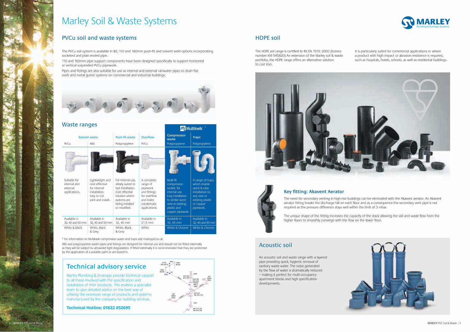
Key fitting: Akavent AeratorThe need for secondary venting in high-rise buildings can be eliminated with the Akavent aerator. An Akavent aerator fitting breaks the discharge fall on each floor and as a consequence the secondary vent pipe is not required as the pressure difference stays well within the limit of 3 mbar.
The unique shape of the fitting increases the capacity of the stack allowing the soil and waste flow from the higher floors to smoothly converge with the flow on the lower floor.
Solvent waste Push-fit waste OverflowCompression waste
Traps
PVCu ABS Polypropylene PVCu Polypropylene Polypropylene
Suitable for internal and external applications.
Lightweight and cost effective for internal installation. Easy to cut joint and install.
For internal use, ideally suited to fast installation. Cost effective solution where systems are being installed or modified.
A complete range of pipework and fittings for overflow and boiler condensate applications.
Multi-fit compression socket, for internal use. Easy installation to similar sized new or existing plastic and copper pipework.
A range of traps, which enable quick & easy installation to any new or existing plastic or copper pipework.
Available in 32, 40 and 50 mm
Available in 32, 40 and 50 mm
Available in 32, 40 mm
Available in 21.5 mm
Available in 32, 40 mm
Available in 32, 40 and 50 mm
White & Black White, Black & Grey
White, Black & Grey
White White & Chrome White & Chrome
The HDPE soil range is certified to BS EN 1519: 2000 (licence number KM 545820) An extension of the Marley soil & waste portfolio, the HDPE range offers an alternative solution to cast iron.
It is particularly suited for commercial applications or where a product with high impact or abrasion resistance is required, such as hospitals, hotels, schools, as well as residential buildings.
* For information on Multikwik compression waste and traps visit marleypd.co.uk.
ABS and polypropylene waste pipes and fittings are designed for internal use and should not be fitted externally as they will be subject to ultraviolet light degradation. If fitted externally it is recommended that they are protected by the application of a suitable paint or are boxed in.
Technical advisory serviceMarley Plumbing & Drainage provide technical support to all those involved with the specification and installation of their products. This enables a specialist team to give detailed advice on the best way of utilising the extensive range of products and systems manufactured by the company for building services.
Technical Hotline: 01622 852695UFC1
S411195S421150
SVD4KT2
KAP2
KAP2
2No KR210
S201156S411195GW059
40mm
110mm
110mm
WCSBS40MKS2
WCSBS40MKS2
WHBB032R
WHBB032R
S2411034No S411195
2No S1211453No S411195
KBA22KB22
KXT21
HDPE soil
Waste ranges
PVCu soil and waste systems
An acoustic soil and waste range with a layered pipe providing quick, hygienic removal of sanitary waste water. The noise generated by the flow of water is dramatically reduced – making it perfect for multi-occupancy apartment blocks and high specification developments.
Acoustic soil
Marley Soil & Waste Systems
The PVCu soil system is available in 82, 110 and 160mm push-fit and solvent weld options incorporating socketed and plain ended pipe.
110 and 160mm pipe support components have been designed specifically to support horizontal or vertical suspended PVCu pipework.
Pipes and fittings are also suitable for use as internal and external rainwater pipes to drain flat roofs and metal gutter systems on commercial and industrial buildings.
*
4 | MARLEY PVC Soil & Waste
MARLEY PVC Soil & Waste || MARLEY PVC Soil & Waste 76
Solvent waste – PVCu
PIPESize mm Code Length Colour Qty
32 KP104 4m W B 10
40 KP204 4m W B 10
50 KP304 4m W B 5
Double spigot
STRAIGHT COUPLINGSSize mm Code A B Colour Qty
32 KSC1 46 20 W B 60
40 KSC2 53 24 W B 30
50 KSC3 66 28 W B 30
Size mm Code A B C Colour Qty
32 KEC1 86 61 20 W 10
40 KEC2 90 64 23 W 10
50 KEC3 82 50 30 W 10
Expansion/adaptor
PIPE CLIPSSize mm Code A B Colour Qty
32 KF1 57 30 W B G 100
40 KF2 62 30 W B G 100
50 KF3 77 41 W B G 80
Open PVCu
Size mm Code A B Colour Qty
32 WC3 76 30 W B 100
40 WC4 82 30 W B 100
50 WC5 100 38 W 80
Saddle
BENDSSize mm Code Angle A B Colour Qty
32 KB1 88½° 57 18 W B 50
40 KB2 88½° 62 21 W B 30
50 KB3 88½° 78 28 W B 10
Solvent sockets
Size mm Code Angle A B Colour Qty
32 KB12 45° 29 18 W B 10
40 KB22 45° 33 21 W B 20
50 KB32 45° 42 28 W B 20
Solvent sockets
Size mm Code Angle A B Colour Qty
32 KBA12 45° 24 23 W 40
40 KBA22 45° 35 26 W 20
Solvent socket/spigot
B
A
B
A
C
B
A
B
A
B
A
B
A
B
A
C
B
A
B
A
B
A
B
A
B
A
C
B
A
B
A
B
A
B
A
B
A
C
B
A
B
A
B
A
B
A
B
A
C
B
A
B
A
B
A
B
A
B
A
C
B
A
B
A
B
A
B
A
B
A
A
BC
B
A
B
A
B
A
B
A
B
A
A
BC
B
A
B
A
B
A
BENDSSize mm Code Angle A B C D Colour Qty
40 KBK25 90° 48 48 23 23 W B 20
50 KBK35 90° 59 50 20 28 W 10
Knuckle bend/boss adaptor KBK35 is a Radius Bend which can solvent weld over a boss upstand
Size mm Code Angle A B Colour Qty
32 KBS1 87½° 92 18 W 20
40 KBS2 87½° 92 23 W 20
Solvent socket/spigot
TEESSize mm Code Angle A B Colour Qty
32 KT1 88½° 92 57 W B 30
40 KT2 88½° 106 62 W B 20
50 KT3 88½° 135 78 W B 10
Solvent sockets
Size mm Code Angle A B Colour Qty
40 KT21 45° 117 78 W 20
50 KT31 45° 149 100 W 10
Solvent sockets
CROSS TEESize mm Code Angle A B Colour Qty
40 KXT21 88½° 106 62 W 10
50 KXT31 88½° 140 87 W 10
Solvent sockets
ACCESS PLUGSize mm Code A B C Colour Qty
32 KAP1 22 53 8 W B 10
40 KAP2 25 57 8 W B 10
50 KAP3 33 71 8 W B 10SOCKET REDUCERSize mm Code A B Colour Qty
32-21.5 KR175 22 20 W 100
40-32 KR210 28 22 W B 80
50-32 KR310 32 28 W 40
50-40 KR320 32 28 W B 40
Solvent spigot/socketIRON ADAPTORS
Female
Size mm Code A B C Colour Qty
32 KFA1 50 25 20 W 10
40 KFA2 53 25 24 W 10
50 KFA3 60 25 28 W 10
Solvent socket/BSP thread
Male
Size mm Code A B C Colour Qty
32 KMA1 44 20 20 W 50
40 KMA2 47 20 24 W 40
50 KMA3 53 20 28 W 40
Solvent socket/BSP thread
B
A
B
A
A
BC
B
A
B
A
B
A
B
A
B
A
A
BC
B
A
B
A
B
A
B
A
B
A
A
BC
B
A
B
A
B
A
B
A
B
A
A
B C
A
BC
A
B
B
A
C
A
B
A
B
A
A
B C
A
BC
A
B
B
A
C
A
B
A
B
A
A
B C
A
BC
A
B
B
A
C
A
B
A
B
A
A
B C
A
BC
A
B
B
A
C
A
B
A
B
A
A
B C
A
BC
A
B
B
A
C
A
BD
AC
A
C
B
D
E
A
C
B
D
C
A
B
A
C
B
PVCc Solvent weld pipe is manufactured to BS EN 1566 CAD drawing available to download from marleypd.co.ukPVCu Solvent weld fittings are manufactured to BS 5255
PVCc Solvent weld pipe is manufactured to BS EN 1566PVCu Solvent weld fittings are manufactured to BS 5255
98 MARLEY PVC Soil & Waste || MARLEY PVC Soil & Waste
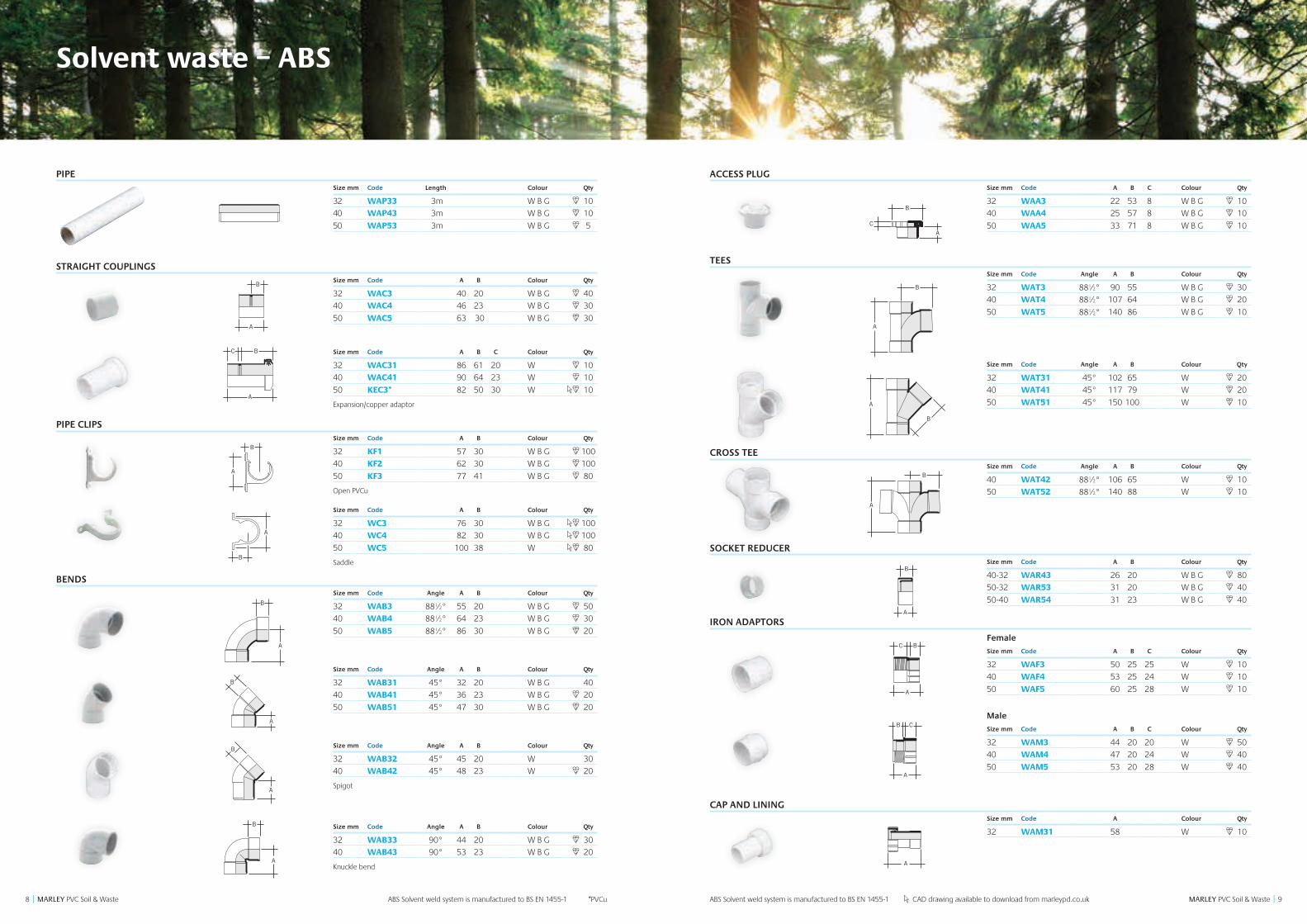
Solvent waste – ABS
PIPESize mm Code Length Colour Qty
32 WAP33 3m W B G 10
40 WAP43 3m W B G 10
50 WAP53 3m W B G 5
STRAIGHT COUPLINGSSize mm Code A B Colour Qty
32 WAC3 40 20 W B G 40
40 WAC4 46 23 W B G 30
50 WAC5 63 30 W B G 30
Size mm Code A B C Colour Qty
32 WAC31 86 61 20 W 10
40 WAC41 90 64 23 W 10
50 KEC3* 82 50 30 W 10
Expansion/copper adaptor
PIPE CLIPSSize mm Code A B Colour Qty
32 KF1 57 30 W B G 100
40 KF2 62 30 W B G 100
50 KF3 77 41 W B G 80
Open PVCu
Size mm Code A B Colour Qty
32 WC3 76 30 W B G 100
40 WC4 82 30 W B G 100
50 WC5 100 38 W 80
Saddle
BENDSSize mm Code Angle A B Colour Qty
32 WAB3 88½° 55 20 W B G 50
40 WAB4 88½° 64 23 W B G 30
50 WAB5 88½° 86 30 W B G 20
Size mm Code Angle A B Colour Qty
32 WAB31 45° 32 20 W B G 40
40 WAB41 45° 36 23 W B G 20
50 WAB51 45° 47 30 W B G 20
Size mm Code Angle A B Colour Qty
32 WAB32 45° 45 20 W 30
40 WAB42 45° 48 23 W 20
Spigot
Size mm Code Angle A B Colour Qty
32 WAB33 90° 44 20 W B G 30
40 WAB43 90° 53 23 W B G 20
Knuckle bend
B
A
B
A
C
B
A
B
A
B
A
B
A
B
A
C
B
A
B
A
B
A
B
A
B
A
C
B
A
B
A
B
A
B
A
B
A
C
B
A
B
A
B
A
B
A
B
A
C
B
A
B
A
B
A
B
A
B
A
C
B
A
B
A
B
A
B
A
B
A
A
BC
B
A
B
A
B
A
B
A
B
A
A
BC
B
A
B
A
B
A
ACCESS PLUGSize mm Code A B C Colour Qty
32 WAA3 22 53 8 W B G 10
40 WAA4 25 57 8 W B G 10
50 WAA5 33 71 8 W B G 10
TEESSize mm Code Angle A B Colour Qty
32 WAT3 88½° 90 55 W B G 30
40 WAT4 88½° 107 64 W B G 20
50 WAT5 88½° 140 86 W B G 10
Size mm Code Angle A B Colour Qty
32 WAT31 45° 102 65 W 20
40 WAT41 45° 117 79 W 20
50 WAT51 45° 150 100 W 10
CROSS TEESize mm Code Angle A B Colour Qty
40 WAT42 88½° 106 65 W 10
50 WAT52 88½° 140 88 W 10
SOCKET REDUCERSize mm Code A B Colour Qty
40-32 WAR43 26 20 W B G 80
50-32 WAR53 31 20 W B G 40
50-40 WAR54 31 23 W B G 40
IRON ADAPTORS
Female
Size mm Code A B C Colour Qty
32 WAF3 50 25 25 W 10
40 WAF4 53 25 24 W 10
50 WAF5 60 25 28 W 10
Male
Size mm Code A B C Colour Qty
32 WAM3 44 20 20 W 50
40 WAM4 47 20 24 W 40
50 WAM5 53 20 28 W 40
CAP AND LININGSize mm Code A Colour Qty
32 WAM31 58 W 10
B
A
B
A
A
BC
B
A
B
A
B
A
B
A
B
A
A
BC
B
A
B
A
B
AB
A
B
A
C
B
A
A
B C
A
B
A
BC
A
B
A
B
A
C
B
A
A
B C
A
B
A
BC
A
B
A
B
A
C
B
A
A
B C
A
B
A
BC
A
B
A
B
A
C
B
A
A
B C
A
B
A
BC
A
B
A
B
A
C
B
A
A
B C
A
B
A
BC
A
B
A
B
A
C
B
A
A
B C
A
B
A
BC
AA
B
ABS Solvent weld system is manufactured to BS EN 1455-1 CAD drawing available to download from marleypd.co.ukABS Solvent weld system is manufactured to BS EN 1455-1 *PVCu
1110 MARLEY PVC Soil & Waste || MARLEY PVC Soil & Waste
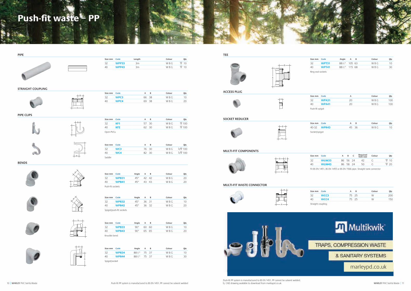
Push-fit waste – PP
PIPESize mm Code Length Colour Qty
32 WPP33 3m W B G 10
40 WPP43 3m W B G 10
STRAIGHT COUPLINGSize mm Code A B Colour Qty
32 WPC3 66 38 W B G 10
40 WPC4 69 38 W B G 20
PIPE CLIPSSize mm Code A B Colour Qty
32 KF1 57 30 W B G 100
40 KF2 62 30 W B G 100
Open PVCu
Size mm Code A B Colour Qty
32 WC3 76 30 W B G 100
40 WC4 82 30 W B G 100
Saddle
BENDS
Size mm Code Angle A B Colour Qty
32 WPB31 45° 42 42 W B G 20
40 WPB41 45° 43 43 W B G 20
Push-fit sockets
Size mm Code Angle A B Colour Qty
32 WPB32 45° 36 31 W B G 10
40 WPB42 45° 36 32 W B G 20
Spigot/push-fit sockets
Size mm Code Angle A B Colour Qty
32 WPB33 90° 60 60 W B G 10
40 WPB43 90° 65 65 W B G 20
Knuckle bend
Size mm Code Angle A B Colour Qty
32 WPB34 88½° 75 37 W B G 10
40 WPB44 88½° 75 37 W B G 30
Spigot/socket
B
A
B
A
C
B
A
B
A
B
A
B
A
B
A
C
B
A
B
A
B
A
B
A
B
A
C
B
A
B
A
B
A
B
A
B
A
B
A
B
A
B
A
B
A
B
A
B
A
B
A
A
B
B
A
B
A
A
B
A
A
B
B
A
B
A
A
B
A
TEESize mm Code Angle A B Colour Qty
32 WPT31 88½° 105 63 W B G 10
40 WPT41 88½° 115 68 W B G 30
Ring seal sockets
ACCESS PLUGSize mm Code A Colour Qty
32 WPA31 20 W B G 100
40 WPA41 20 W B G 100
Push-fit spigot
SOCKET REDUCERSize mm Code A B Colour Qty
40-32 WPR43 45 36 W B G 10
Socket/spigot
MULTI-FIT COMPONENTS
Size mm Code A B C Required hole size Colour Qty
32 WUM33 86 56 24 42 G 10
40 WUM43 86 58 24 50 G 20
Fit BS EN 1451, BS EN 1455 or BS EN 1566 pipe. Straight tank connector
MULTI-FIT WASTE CONNECTOR
Size mm Code A B Colour Qty
32 WCC3 75 25 W 200
40 WCC4 75 25 W 150
Straight coupling
A
B
B
A
B
A
A
B
A
A
B
B
A
B
A
A
B
A
A
B
B
A
B
A
A
B
A
A
B C
B
A
A
B C
B
A
Push-fit PP system is manufactured to BS EN 1451. PP cannot be solvent welded. CAD drawing available to download from marleypd.co.ukPush-fit PP system is manufactured to BS EN 1451. PP cannot be solvent welded
marleypd.co.uk
1312 MARLEY PVC Soil & Waste || MARLEY PVC Soil & Waste
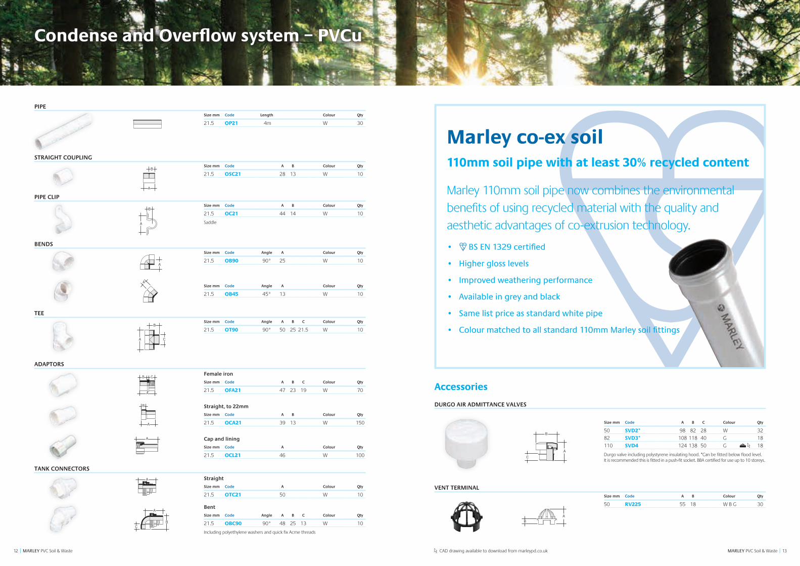
PIPESize mm Code Length Colour Qty
21.5 OP21 4m W 30
STRAIGHT COUPLINGSize mm Code A B Colour Qty
21.5 OSC21 28 13 W 10
PIPE CLIPSize mm Code A B Colour Qty
21.5 OC21 44 14 W 10
Saddle
BENDSSize mm Code Angle A Colour Qty
21.5 OB90 90° 25 W 10
Size mm Code Angle A Colour Qty
21.5 OB45 45° 13 W 10
TEESize mm Code Angle A B C Colour Qty
21.5 OT90 90° 50 25 21.5 W 10
ADAPTORS
Female iron
Size mm Code A B C Colour Qty
21.5 OFA21 47 23 19 W 70
Straight, to 22mm
Size mm Code A B Colour Qty
21.5 OCA21 39 13 W 150
Cap and lining
Size mm Code A Colour Qty
21.5 OCL21 46 W 100
TANK CONNECTORS
Straight
Size mm Code A Colour Qty
21.5 OTC21 50 W 10
Bent
Size mm Code Angle A B C Colour Qty
21.5 OBC90 90° 48 25 13 W 10
Including polyethylene washers and quick fix Acme threads
C
B
A
A
A
A
B
B
A
A
B C
A
B
A
A
A
CB
C
B
A
A
A
A
B
B
A
A
B C
A
B
A
A
A
CB
C
B
A
A
A
A
B
B
A
A
B C
A
B
A
A
A
CB
C
B
A
A
A
A
B
B
A
A
B C
A
B
A
A
A
CB
C
B
A
A
A
A
B
B
A
A
B C
A
B
A
A
A
CB
C
B
A
A
A
A
B
B
A
A
B C
A
B
A
A
A
CB
C
B
A
A
A
A
B
B
A
A
B C
A
B
A
A
A
CB
C
B
A
A
A
A
B
B
A
A
B C
A
B
A
A
A
CB
C
B
A
A
A
A
B
B
A
A
B C
A
B
A
A
A
CB
C
B
A
A
A
A
B
B
A
A
B C
A
B
A
A
A
CB
C
B
A
A
A
A
B
B
A
A
B C
A
B
A
A
A
CB
Accessories
DURGO AIR ADMITTANCE VALVES
Size mm Code A B C Colour Qty
50 SVD2* 98 82 28 W 32
82 SVD3* 108 118 40 G 18
110 SVD4 124 138 50 G 18
Durgo valve including polystyrene insulating hood. *Can be fitted below flood level. It is recommended this is fitted in a push-fit socket. BBA certified for use up to 10 storeys.
VENT TERMINALSize mm Code A B Colour Qty
50 RV225 55 18 W B G 30
A
C
B
B
A
C
AB
A
C
B
B
A
C
AB
Marley 110mm soil pipe now combines the environmental benefits of using recycled material with the quality and aesthetic advantages of co-extrusion technology.
• BS EN 1329 certified
• Higher gloss levels
• Improved weathering performance
• Available in grey and black
• Same list price as standard white pipe
• Colour matched to all standard 110mm Marley soil fittings
Marley co-ex soil110mm soil pipe with at least 30% recycled content
Condense and Overflow system – PVCu
CAD drawing available to download from marleypd.co.uk
1514 MARLEY PVC Soil & Waste || MARLEY PVC Soil & Waste
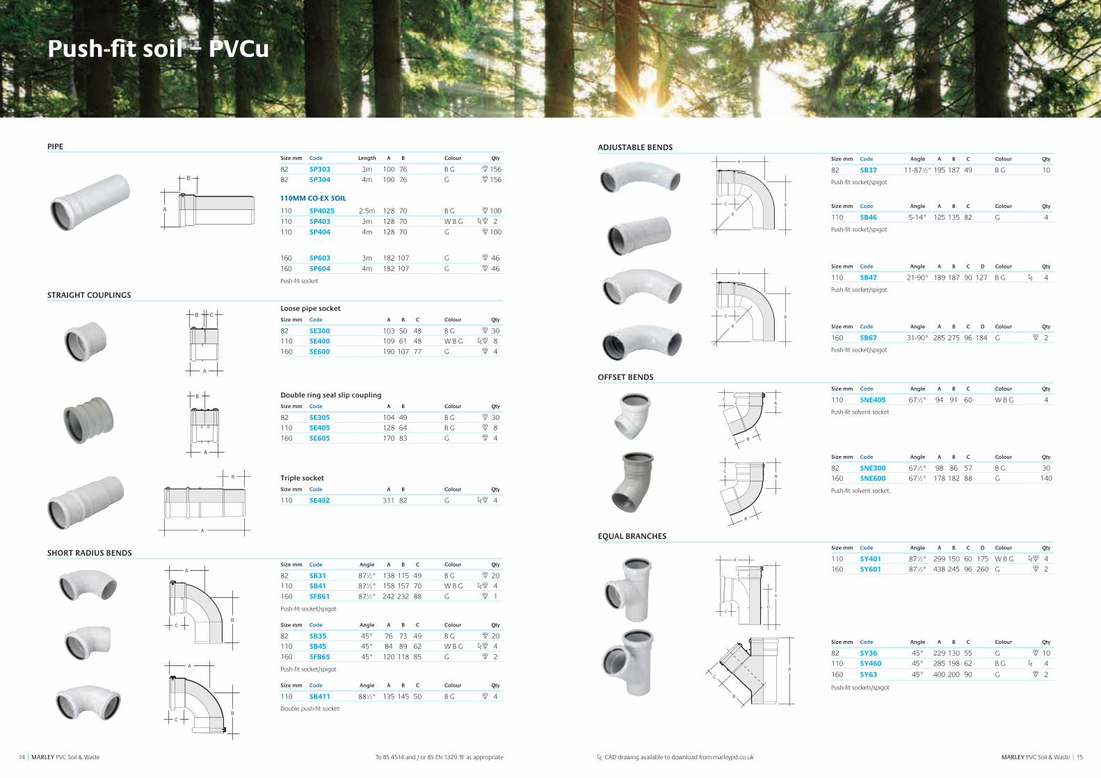
Push-fit soil – PVCu
PIPESize mm Code Length A B Colour Qty
82 SP303 3m 100 76 B G 156
82 SP304 4m 100 76 G 156
110 SP4025 2.5m 128 70 B G 100
110 SP403 3m 128 70 W B G 2
110 SP404 4m 128 70 G 100
160 SP603 3m 182 107 G 46
160 SP604 4m 182 107 G 46
Push-fit socket
STRAIGHT COUPLINGS
Loose pipe socket
Size mm Code A B C Colour Qty
82 SE300 103 50 48 B G 30
110 SE400 109 61 48 W B G 8
160 SE600 190 107 77 G 4
Double ring seal slip coupling
Size mm Code A B Colour Qty
82 SE305 104 49 B G 30
110 SE405 128 64 B G 8
160 SE605 170 83 G 4
Triple socket
Size mm Code A B Colour Qty
110 SE402 311 82 G 4
SHORT RADIUS BENDSSize mm Code Angle A B C Colour Qty
82 SB31 87½° 138 115 49 B G 20
110 SB41 87½° 158 157 70 W B G 4
160 SFB61 87½° 242 232 88 G 1
Push-fit socket/spigot
Size mm Code Angle A B C Colour Qty
82 SB35 45° 76 73 49 B G 20
110 SB45 45° 84 89 62 W B G 4
160 SFB65 45° 120 118 85 G 2
Push-fit socket/spigot
Size mm Code Angle A B C Colour Qty
110 SB411 88½° 135 145 50 B G 4
Double push-fit socket
ADJUSTABLE BENDSSize mm Code Angle A B C Colour Qty
82 SB37 11-87½° 195 187 49 B G 10
Push-fit socket/spigot
Size mm Code Angle A B C Colour Qty
110 SB46 5-14° 125 135 82 G 4
Push-fit socket/spigot
Size mm Code Angle A B C D Colour Qty
110 SB47 21-90° 189 187 90 127 B G 4
Push-fit socket/spigot
Size mm Code Angle A B C D Colour Qty
160 SB67 31-90° 285 275 96 184 G 2
Push-fit socket/spigot
OFFSET BENDSSize mm Code Angle A B C Colour Qty
110 SNE405 67½° 94 91 60 W B G 4
Push-fit solvent socket
Size mm Code Angle A B C Colour Qty
82 SNE300 67½° 98 86 57 B G 30
160 SNE600 67½° 178 182 88 G 140
Push-fit solvent socket.
EQUAL BRANCHESSize mm Code Angle A B C D Colour Qty
110 SY401 87½° 299 150 60 175 W B G 4
160 SY601 87½° 438 245 96 260 G 2
Size mm Code Angle A B C Colour Qty
82 SY36 45° 229 130 55 G 10
110 SY460 45° 285 198 62 B G 4
160 SY63 45° 400 200 90 G 2
Push-fit sockets/spigot
B
A
B
A
C
B
A
B
A
A C
B
B
A
C
B
A
C
A
B
BC
A
BC
A
CB
A
A
B
C
BC
A
BC
A
BC
A
CB
A
A
B
C
BC
A
A
B
C
AC
B
A
BC
D
B
A
D
C
BC
A
B
A
B
A
C
B
A
AC
B
A
B
C
A
B
C
AC
B
A
BC
D
B
A
D
C
BC
A
BD
AC
A
C
B
D
76
A
C
B
D
C
A
B
A
C
B
A
B
C
CAD drawing available to download from marleypd.co.uk
110MM CO-EX SOIL
To BS 4514 and / or BS EN 1329 'B' as appropriate
1716 MARLEY PVC Soil & Waste || MARLEY PVC Soil & Waste
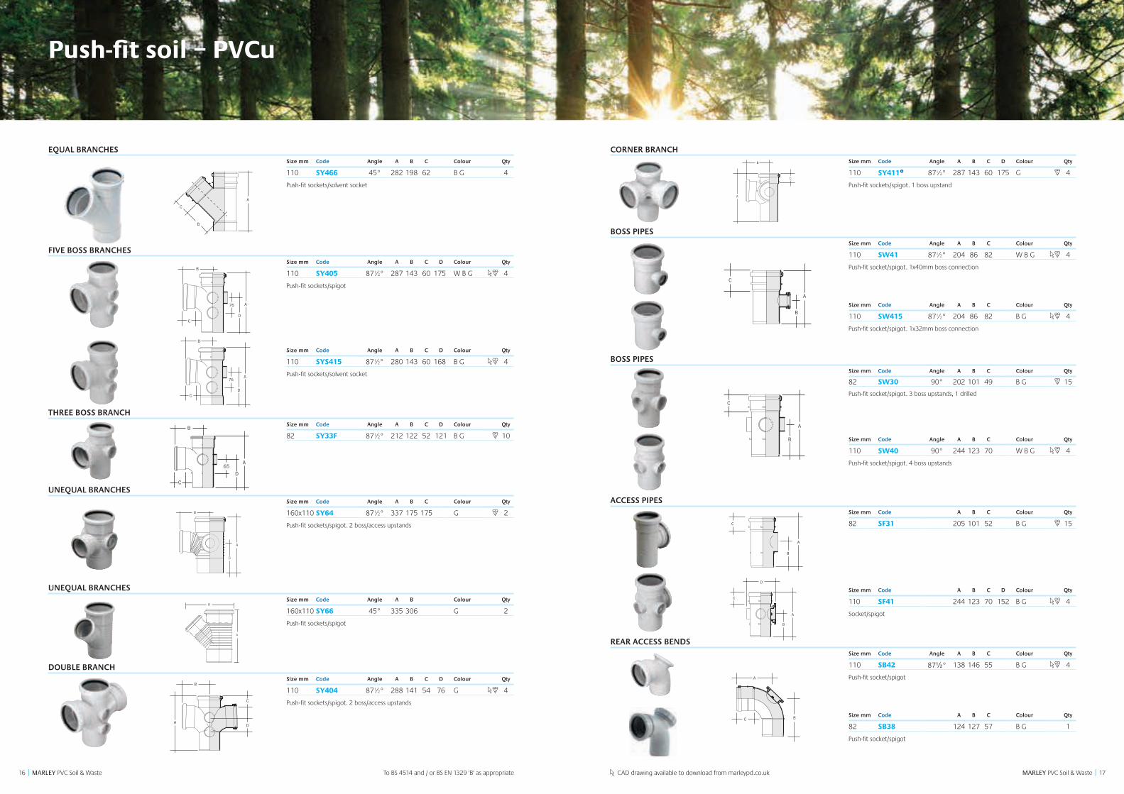
CORNER BRANCHSize mm Code Angle A B C D Colour Qty
110 SY411£ 87½° 287 143 60 175 G 4
Push-fit sockets/spigot. 1 boss upstand
BOSS PIPESSize mm Code Angle A B C Colour Qty
110 SW41 87½° 204 86 82 W B G 4
Push-fit socket/spigot. 1x40mm boss connection
Size mm Code Angle A B C Colour Qty
110 SW415 87½° 204 86 82 B G 4
Push-fit socket/spigot. 1x32mm boss connection
BOSS PIPESSize mm Code Angle A B C Colour Qty
82 SW30 90° 202 101 49 B G 15
Push-fit socket/spigot. 3 boss upstands, 1 drilled
Size mm Code Angle A B C Colour Qty
110 SW40 90° 244 123 70 W B G 4
Push-fit socket/spigot. 4 boss upstands
ACCESS PIPESSize mm Code A B C Colour Qty
82 SF31 205 101 52 B G 15
Size mm Code A B C D Colour Qty
110 SF41 244 123 70 152 B G 4
Socket/spigot
REAR ACCESS BENDSSize mm Code Angle A B C Colour Qty
110 SB42 87½° 138 146 55 B G 4
Push-fit socket/spigot
Size mm Code A B C Colour Qty
82 SB38 124 127 57 B G 1
Push-fit socket/spigot
A
B
B
A
C
C
B
A
A
A
C
B
CB
A
C
B
A
C
B
Push-fit soil – PVCu
EQUAL BRANCHESSize mm Code Angle A B C Colour Qty
110 SY466 45° 282 198 62 B G 4
Push-fit sockets/solvent socket
FIVE BOSS BRANCHESSize mm Code Angle A B C D Colour Qty
110 SY405 87½° 287 143 60 175 W B G 4
Push-fit sockets/spigot
Size mm Code Angle A B C D Colour Qty
110 SYS415 87½° 280 143 60 168 B G 4
Push-fit sockets/solvent socket
THREE BOSS BRANCHSize mm Code Angle A B C D Colour Qty
82 SY33F 87½° 212 122 52 121 B G 10
UNEQUAL BRANCHESSize mm Code Angle A B C Colour Qty
160x110 SY64 87½° 337 175 175 G 2
Push-fit sockets/spigot. 2 boss/access upstands
UNEQUAL BRANCHESSize mm Code Angle A B Colour Qty
160x110 SY66 45° 335 306 G 2
Push-fit sockets/spigot
DOUBLE BRANCHSize mm Code Angle A B C D Colour Qty
110 SY404 87½° 288 141 54 76 G 4
Push-fit sockets/spigot. 2 boss/access upstands
BD
AC
A
C
B
D
76
A
C
B
D
C
A
B
A
C
B
A
C
B
D
76
A
C
B
D
E
SYS415
A
C
B
D
76
SYS405
A
B
C
A
B
C
A
C
B
D
C
B
A
A
C
B
D65
SY33F
A
B
C
A
B
C
A
C
B
D
C
B
A
A
C
B
D65
SY33F
To BS 4514 and / or BS EN 1329 'B' as appropriate
A
B
C
B
A
C
C
B
A
A
A
C
B
CB
A
C
B
A
C
B
CAD drawing available to download from marleypd.co.uk
B
A
C
C
B
A
A
A
C
B
CB
A
C
B
A
C
B
A
C
B
F
E A
C
B
D
A
B C
B
A
B
A
A
A
C
C
B
B
D
D
A
B
C
A
B
C
A
C
B
D
C
B
A
A
C
B
D65
SY33F
A
BC
1918 MARLEY PVC Soil & Waste || MARLEY PVC Soil & Waste
CAB
CAB
B
A
B
A
A
B
A
C
B
C B
A
C
B
A
CA
B
C
A
BD
110mm 500mm
750mm
12
3
BA
AC
B
B
A
C B
A
C
A
B
AB
C
SA110
A
C
B
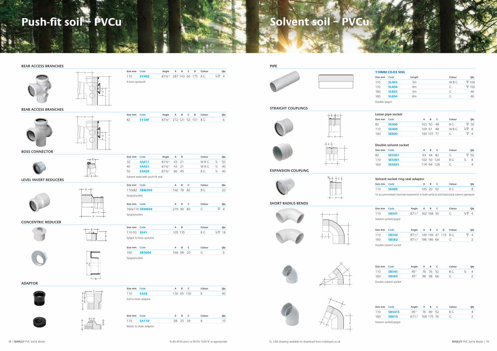
REAR ACCESS BRANCHESSize mm Code Angle A B C D Colour Qty
110 SY402 87½° 287 143 60 175 B G 4
4 boss upstands
REAR ACCESS BRANCHESSize mm Code Angle A B C D Colour Qty
82 SY34F 87½° 212 121 52 101 B G 6
BOSS CONNECTORSize mm Code Angle A B Colour Qty
32 SA411 87½° 43 21 W B G 50
40 SA421 87½° 43 21 W B G 40
50 SA420 87½° 66 45 B G 40
Solvent weld with push-fit sealLEVEL INVERT REDUCERS
Size mm Code A B C Colour Qty
110x82 SRM304 192 78 82 B G 20
Spigot/socket
Size mm Code A B C Colour Qty
160x110 SRM604 219 90 82 G 4
Spigot/socket
CONCENTRIC REDUCERSize mm Code A B Colour Qty
110-50 SE41 105 135 B G 18
Spigot to boss upstand
Size mm Code A B C Colour Qty
160 SRS604 168 68 20 G 6
Spigot/socket
ADAPTORSize mm Code A B C Colour Qty
110 SA42 130 65 130 B 40
Soil to drain adaptor
Size mm Code A B C Colour Qty
110 SA110 58 25 34 B 10
Waste to drain adaptor
Push-fit soil – PVCu
To BS 4514 and / or BS EN 1329 'B' as appropriate
A
B
C
A
C
B
A
C
B
D
76
A
C
B
A
B
C
A
C
B
A
C
B
D
76
A
C
B
CAD drawing available to download from marleypd.co.uk
CAB
CAB
B
A
B
A
A
B
A
C
B
C B
A
C
B
A
CA
B
C
A
BD
110mm 500mm
750mm
12
3
BA
C
B
A
Solvent soil – PVCu
PIPE
110MM CO-EX SOIL
Size mm Code Length Colour Qty
110 SL403 3m W B G 100
110 SL404 4m G 100
160 SL603 3m G 46
160 SL604 4m G 46
Double spigot
STRAIGHT COUPLINGS
Loose pipe socket
Size mm Code A B C Colour Qty
82 SE300 103 50 48 B G 30
110 SE400 109 61 48 W B G 8
160 SE600 190 107 77 G 4
Double solvent socket
Size mm Code A B C Colour Qty
82 SES301 93 44 82 G 50
110 SES401 102 50 124 B G 8
160 SES601 174 64 128 G 4
EXPANSION COUPLING
Solvent socket ring seal adaptor
Size mm Code A B C Colour Qty
110 SE409 105 20 52 B G 8
To accommodate thermal movement in both vertical and horizontal solvent pipework
SHORT RADIUS BENDSSize mm Code Angle A B C Colour Qty
110 SBS41 87½° 162 168 50 G 4
Solvent socket/spigot
Size mm Code Angle A B C D Colour Qty
110 SBS42 87½° 149 149 47 119 B G 4
160 SBS62 87½° 186 186 66 G 2
Double solvent socket
Size mm Code Angle A B C Colour Qty
110 SBS45 45° 76 76 52 B G 4
160 SBS65 45° 98 98 66 G 2
Double solvent socket
Size mm Code Angle A B C Colour Qty
110 SBS415 45° 76 89 52 B G 4
160 SB615 67½° 168 175 76 G 2
Solvent socket/spigot
B
A
B
A
C
B
A
C
A
B
B
A
C
BC
A
BC
A
CB
A
A
B
C
BC
A
BC
A
BC
A
CB
A
A
B
C
BC
A
A
BC
B
A
B
A
C
B
A
B
A
B
A
C
B
A
2120 MARLEY PVC Soil & Waste || MARLEY PVC Soil & Waste
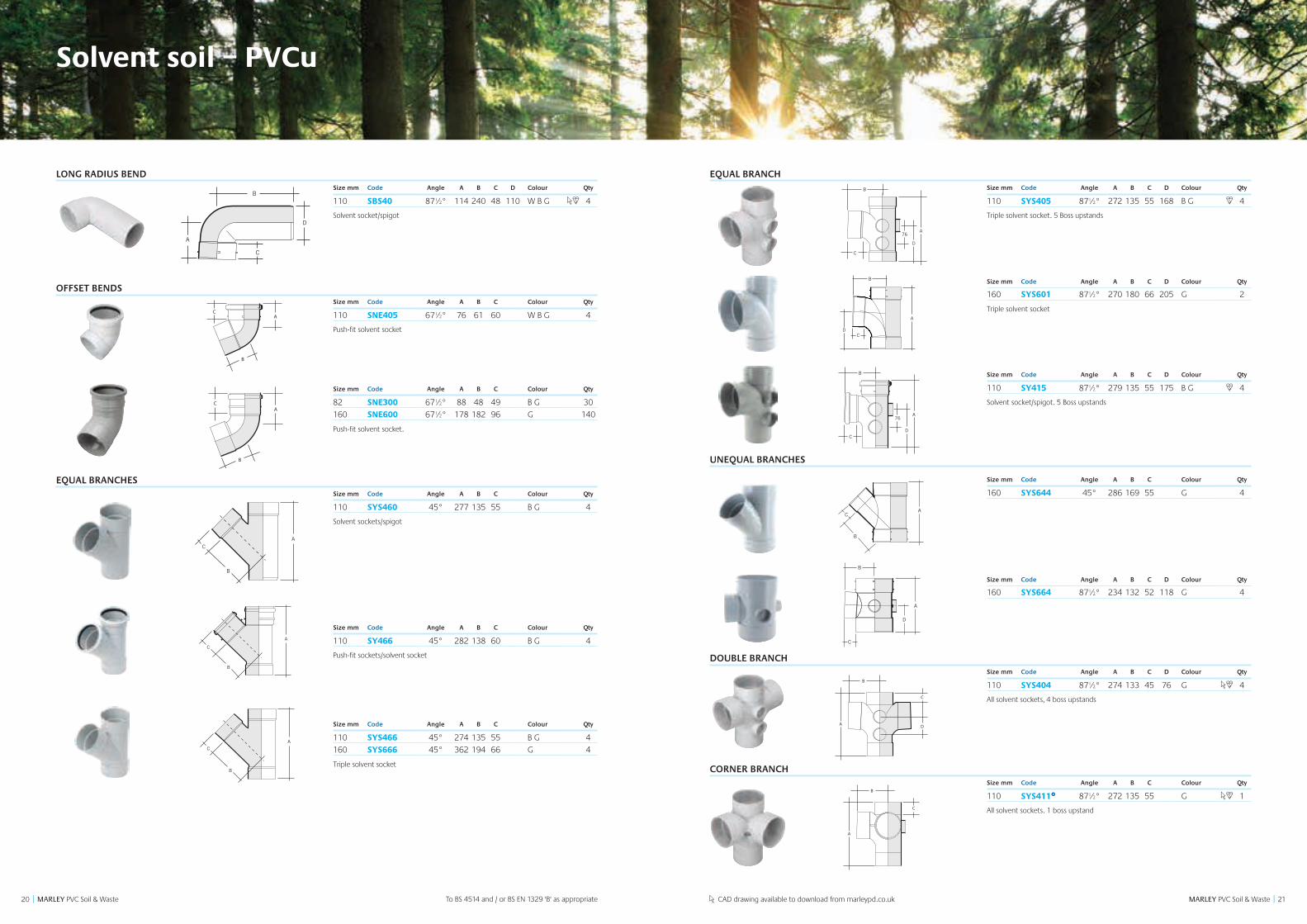
LONG RADIUS BENDSize mm Code Angle A B C D Colour Qty
110 SBS40 87½° 114 240 48 110 W B G 4
Solvent socket/spigot
OFFSET BENDSSize mm Code Angle A B C Colour Qty
110 SNE405 67½° 76 61 60 W B G 4
Push-fit solvent socket
Size mm Code Angle A B C Colour Qty
82 SNE300 67½° 88 48 49 B G 30
160 SNE600 67½° 178 182 96 G 140
Push-fit solvent socket.
EQUAL BRANCHESSize mm Code Angle A B C Colour Qty
110 SYS460 45° 277 135 55 B G 4
Solvent sockets/spigot
Size mm Code Angle A B C Colour Qty
110 SY466 45° 282 138 60 B G 4
Push-fit sockets/solvent socket
Size mm Code Angle A B C Colour Qty
110 SYS466 45° 274 135 55 B G 4
160 SYS666 45° 362 194 66 G 4
Triple solvent socket
A
B
C
Solvent soil – PVCu
A
B
C
AC
B
A
BC
D
B
A
D
C
BC
A
To BS 4514 and / or BS EN 1329 'B' as appropriate
A
B
C
A
B
C
CAD drawing available to download from marleypd.co.uk
AC
B
A
B
C
EQUAL BRANCHSize mm Code Angle A B C D Colour Qty
110 SYS405 87½° 272 135 55 168 B G 4
Triple solvent socket. 5 Boss upstands
Size mm Code Angle A B C D Colour Qty
160 SYS601 87½° 270 180 66 205 G 2
Triple solvent socket
Size mm Code Angle A B C D Colour Qty
110 SY415 87½° 279 135 55 175 B G 4
Solvent socket/spigot. 5 Boss upstands
UNEQUAL BRANCHES
Size mm Code Angle A B C Colour Qty
160 SYS644 45° 286 169 55 G 4
Size mm Code Angle A B C D Colour Qty
160 SYS664 87½° 234 132 52 118 G 4
DOUBLE BRANCHSize mm Code Angle A B C D Colour Qty
110 SYS404 87½° 274 133 45 76 G 4
All solvent sockets, 4 boss upstands
CORNER BRANCHSize mm Code Angle A B C Colour Qty
110 SYS411£ 87½° 272 135 55 G 1
All solvent sockets. 1 boss upstand
A
C
B
D
B
CA
B
C
A
D
A
C
B
A
C
B
D
76
A
C
B
D
E
SYS415
A
C
B
D
76
SYS405
A
C
B
D
76
SYS415
A
D
B
B
C
B
C
C
A
A
D
2322 MARLEY PVC Soil & Waste || MARLEY PVC Soil & Waste
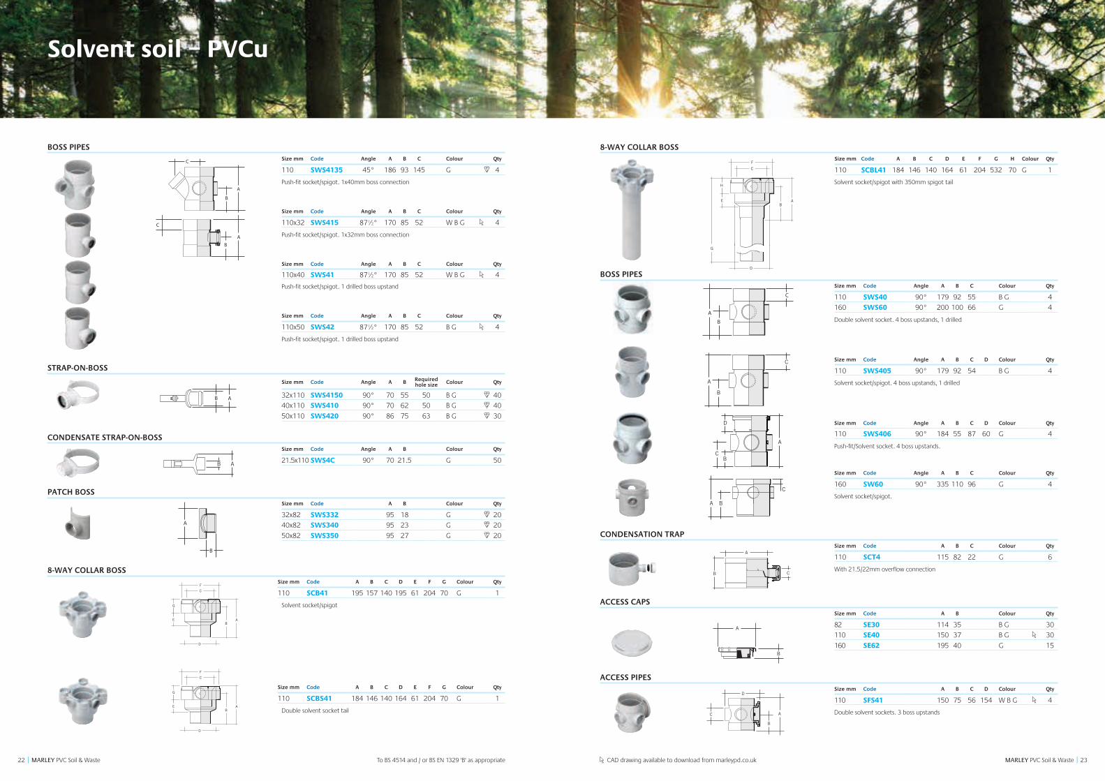
BOSS PIPESSize mm Code Angle A B C Colour Qty
110 SWS4135 45° 186 93 145 G 4
Push-fit socket/spigot. 1x40mm boss connection
Size mm Code Angle A B C Colour Qty
110x32 SWS415 87½° 170 85 52 W B G 4
Push-fit socket/spigot. 1x32mm boss connection
Size mm Code Angle A B C Colour Qty
110x40 SWS41 87½° 170 85 52 W B G 4
Push-fit socket/spigot. 1 drilled boss upstand
Size mm Code Angle A B C Colour Qty
110x50 SWS42 87½° 170 85 52 B G 4
Push-fit socket/spigot. 1 drilled boss upstand
STRAP-ON-BOSS
Size mm Code Angle A B Required hole size Colour Qty
32x110 SWS4150 90° 70 55 50 B G 40
40x110 SWS410 90° 70 62 50 B G 40
50x110 SWS420 90° 86 75 63 B G 30
CONDENSATE STRAP-ON-BOSSSize mm Code Angle A B Colour Qty
21.5x110 SWS4C 90° 70 21.5 G 50
PATCH BOSSSize mm Code A B Colour Qty
32x82 SWS332 95 18 G 20
40x82 SWS340 95 23 G 20
50x82 SWS350 95 27 G 20
8-WAY COLLAR BOSSSize mm Code A B C D E F G Colour Qty
110 SCB41 195 157 140 195 61 204 70 G 1
Solvent socket/spigot
Size mm Code A B C D E F G Colour Qty
110 SCBS41 184 146 140 164 61 204 70 G 1
Double solvent socket tail
To BS 4514 and / or BS EN 1329 'B' as appropriate
Solvent soil – PVCu
A
C
B
A
C
B
C
B
A
B A
B
A
A
C
B
A
C
B
C
B
A
B A
B
A
B A
E
G
D
AB
C
F
E
G
D
AB
C
F
A
C
B
A
C
B
C
B
A
B A
B
A
A
C
B
CAD drawing available to download from marleypd.co.uk
8-WAY COLLAR BOSSSize mm Code A B C D E F G H Colour Qty
110 SCBL41 184 146 140 164 61 204 532 70 G 1
Solvent socket/spigot with 350mm spigot tail
BOSS PIPESSize mm Code Angle A B C Colour Qty
110 SWS40 90° 179 92 55 B G 4
160 SWS60 90° 200 100 66 G 4
Double solvent socket. 4 boss upstands, 1 drilled
Size mm Code Angle A B C D Colour Qty
110 SWS405 90° 179 92 54 B G 4
Solvent socket/spigot. 4 boss upstands, 1 drilled
Size mm Code Angle A B C D Colour Qty
110 SWS406 90° 184 55 87 60 G 4
Push-fit/Solvent socket. 4 boss upstands.
Size mm Code Angle A B C Colour Qty
160 SW60 90° 335 110 96 G 4
Solvent socket/spigot.
CONDENSATION TRAPSize mm Code A B C Colour Qty
110 SCT4 115 82 22 G 6
With 21.5/22mm overflow connection
ACCESS CAPSSize mm Code A B Colour Qty
82 SE30 114 35 B G 30
110 SE40 150 37 B G 30
160 SE62 195 40 G 15
ACCESS PIPESSize mm Code A B C D Colour Qty
110 SFS41 150 75 56 154 W B G 4
Double solvent sockets. 3 boss upstands
F
E A
C
B
D
A
B C
B
A
B
A
A
A
C
C
B
B
D
D
F
E A
C
B
D
A
B C
B
A
B
A
A
A
C
C
B
B
D
D
F
E A
C
B
D
A
B C
B
A
B
A
A
A
C
C
B
B
D
D
A
C
B
E
H
D
A
G
C
B
F
E
D
A
G
C
B
F
G
A
C
B
A
B
D
C
A
C
B
2524 MARLEY PVC Soil & Waste || MARLEY PVC Soil & Waste
ACCESS PIPESSize mm Code A B C D Colour Qty
160 SF611 287 144 138 223 G 2
Double solvent sockets
REAR ACCESS BENDSize mm Code Angle A B C Colour Qty
110 SBS420 87½° 131 128 54 B G 4
Double solvent socket
BOSS CONNECTORS
Size mm Code A B Colour Qty
32 SA415 35 20 G 50
40 SA425 30 25 B G 50
50 SA435 58 28 G 50
Solvent weld with solvent weld joint
Size mm Code Angle A B C D Colour Qty
40 KBK25 90° 48 48 23 23 W B 20
50 KBK35 90° 59 50 20 28 W 10
Solvent weld
Size mm Code A B Colour Qty
32 SA411 43 21 W B G 50
40 SA421 43 21 W B G 40
50 SA420 66 45 B G 40
CONCENTRIC REDUCERS
Size mm Code A B C Colour Qty
110-50 SE41 105 135 B G 18
Spigot to boss upstand. Spigot/Socket
Size mm Code A B C Colour Qty
160-110 SRS604 168 68 20 G 6
Spigot/Socket
ECCENTRIC REDUCERSSize mm Code A B Colour Qty
82-50 SRM30 66 35 B G 90
Spigot tail
Size mm Code A B C Colour Qty
110-50 SRM402 48 25 19 B G 10 Solvent socket to boss upstand
Solvent soil – PVCu
CAB
CAB
B
A
B
A
A
B
A
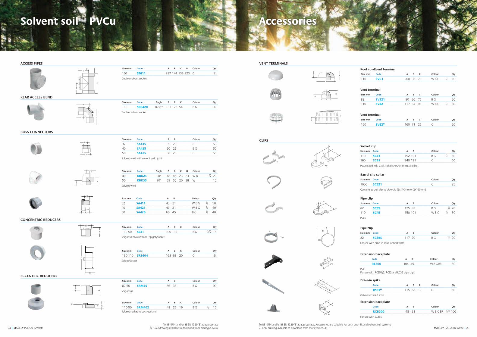
C
B
C B
A
C
B
A
CA
B
C
A
BD
110mm 500mm
750mm
12
3
BA
AB
CAB
CAB
B
A
B
A
A
B
A
C
B
C B
A
C
B
A
CA
B
C
A
BD
110mm 500mm
750mm
12
3
BA
CAB
CAB
B
A
B
A
A
B
A
C
B
C B
A
C
B
A
CA
B
C
A
BD
110mm 500mm
750mm
12
3
BA
A
BC
CAB
CAB
B
A
B
A
A
B
A
C
B
C B
A
C
B
A
CA
B
C
A
BD
110mm 500mm
750mm
12
3
BA
BD
AC
A
C
B
D
76
A
C
B
D
C
A
B
A
C
B
A
C
B
D
CAB
CAB
B
A
B
A
A
B
A
C
B
C B
A
C
B
A
CA
B
C
A
BD
110mm 500mm
750mm
12
3
BA
To BS 4514 and/or BS EN 1329 'B' as appropriate CAD drawing available to download from marleypd.co.uk
CAB
CAB
B
A
B
A
A
B
A
C
B
C B
A
C
B
A
CA
B
C
A
BD
110mm 500mm
750mm
12
3
BA
VENT TERMINALS
Roof cowl/vent terminal
Size mm Code A B C Colour Qty
110 SVC1 200 98 70 W B G 10
Vent terminal
Size mm Code A B C Colour Qty
82 SV321 90 30 75 B G 30
110 SV42 117 34 95 W B G 60
Vent terminal
Size mm Code A B C Colour Qty
160 SV62£ 160 71 25 G 20
CLIPS
Socket clip
Size mm Code A B Colour Qty
110 SC41 152 101 B G 50
160 SC61 240 121 G 50
PVC coated mild steel, includes 6x20mm nut and bolt
Barrel clip collar
Size mm Code Colour Qty
1000 SC621 G 25
Converts socket clip to pipe clip (3x110mm or 2x160mm)
Pipe clip
Size mm Code A B Colour Qty
82 SC35 125 93 B G 20
110 SC45 150 101 W B G 50
PVCu
Pipe clip
Size mm Code A B Colour Qty
82 SC35S 117 70 B G 20
For use with drive-in spike or backplate.
Extension backplate
Code A B Colour Qty
RT200 104 45 W B G BR 50
PVCu For use with RC251/2, RCE2 and RC32 pipe clips
Drive-in spike
Code A B C Colour Qty
RSS1£ 115 58 19 G 50
Galvanised mild steel
Extension backplate
Code A B Colour Qty
RCB300 48 31 W B G BR 100
For use with SC35S
AB
A
B
AC
B
A
B
AB
A
B
AC
B
A
B
AB
A
B
AC
B
A
B
BA
To BS 4514 and/or BS EN 1329 'B' as appropriate. Accessories are suitable for both push-fit and solvent soil systems CAD drawing available to download from marleypd.co.uk
Accessories
C
B
A
Accessories
AB
A
B
AC
B
A
B
AB
A
B
AC
B
A
B
A
A
B
A
B
B
A
A
A
B
B
A
AC
C
B
B
A
B
A
A
27
Product range
26 MARLEY PVC Soil & Waste || MARLEY PVC Soil & Waste
CLIPS
Extension Bracket
Code A B Colour Qty
110 RT250 243 114 B G 20
Cover plate
Code A B Colour Qty
110 RT2501 111 35 B G 1
For use with RT250
Pipe clip
Code A B Colour Qty
110 RPC1 137 111 B G 20
Socket clip
Code A B Colour Qty
110 RSC1 141 119 B G 1
DURGO AIR ADMITTANCE VALVES
Size mm Code A B C Colour Qty
50 SVD2* 98 82 28 W 32
82 SVD3* 108 118 40 G 18
110 SVD4 124 138 50 G 18
Durgo valve including polystyrene insulating hood. *Can be fitted below flood level. It is recommended this is fitted in a push-fit socket
Weathering collar
Size mm Code A B C Colour Qty
82 SV31* 51 94 25 B 100
110 SV43 57 130 25 W B G 35
PVCu for solvent joint to pipe *Available in black rubber only.
WEATHERING SLATESSize mm Code A B Colour Qty
400 SAS40 400 400 G 5
Flat. Manufactured from aluminium and rubber
Size mm Code A B Colour Qty
450 SAS45 450 450 G 5
610 SAS61 610 610 G 5
Inclined. Manufactured from aluminium and rubber
CAD drawing available to download from marleypd.co.uk
Accessories
To BS 4514 and/or BS EN 1329 'B' as appropriate. Accessories are suitable for both push-fit and solvent soil systems
CAB
CAB
B
A
B
A
A
B
A
C
B
C B
A
C
B
A
CA
B
C
A
BD
110mm 500mm
750mm
12
3
BA
CAB
CAB
B
A
B
A
A
B
A
C
B
C B
A
C
B
A
CA
B
C
A
BD
110mm 500mm
750mm
12
3
BA
CAB
CAB
B
A
B
A
A
B
A
C
B
C B
A
C
B
A
CA
B
C
A
BD
110mm 500mm
750mm
12
3
BA
A=111 (HOLE-SAW SIZE)B=35
A
B
WC connectors
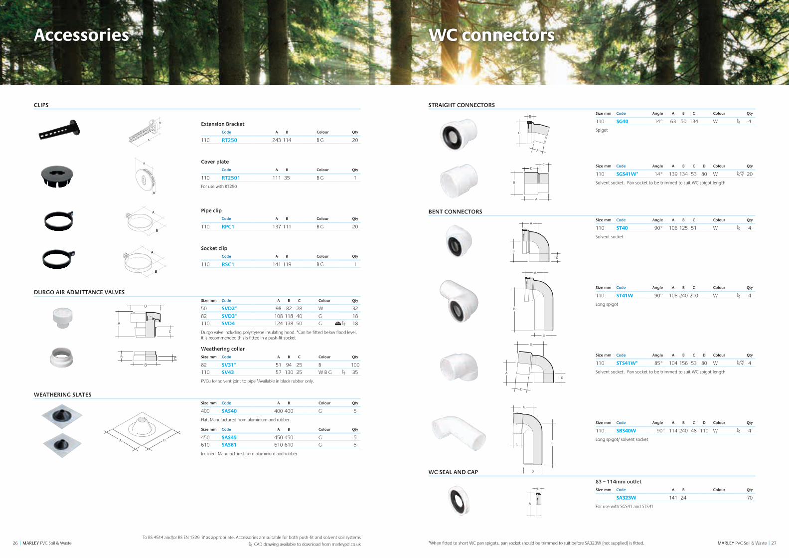
STRAIGHT CONNECTORS Size mm Code Angle A B C Colour Qty
110 SG40 14° 63 50 134 W 4
Spigot
Size mm Code Angle A B C D Colour Qty
110 SGS41W* 14° 139 134 53 80 W 20
Solvent socket. Pan socket to be trimmed to suit WC spigot length
BENT CONNECTORS Size mm Code Angle A B C Colour Qty
110 ST40 90° 106 125 51 W 4
Solvent socket
Size mm Code Angle A B C Colour Qty
110 ST41W 90° 106 240 210 W 4
Long spigot
Size mm Code Angle A B C D Colour Qty
110 STS41W* 85° 104 156 53 80 W 4
Solvent socket. Pan socket to be trimmed to suit WC spigot length
Size mm Code Angle A B C D Colour Qty
110 SBS40W 90° 114 240 48 110 W 4
Long spigot/ solvent socket
WC SEAL AND CAP
83 – 114mm outlet
Size mm Code A B Colour Qty
SA323W 141 24 70
For use with SGS41 and STS41
C
A
B
C
B
A
B
A
C
B
C
A
D
A
B
C
D
B
A
C
A
B
C
B
A
B
A
C
B
C
A
D
A
B
C
D
B
A
C
A
B
C
B
A
B
A
C
B
C
A
D
A
B
C
D
B
A
C
A
B
C
B
A
B
A
C
B
C
A
D
A
B
C
D
B
A
C
A
B
C
B
A
B
A
C
B
C
A
D
A
B
C
D
B
A
A
B
C
AC
B
A
BC
D
B
A
D
C
BC
A
C
A
B
C
B
A
B
A
C
B
C
A
D
A
B
C
D
B
A
WC connectors
A
B
A=137B=111
A
B
A=141B=119
A
B
*When fitted to short WC pan spigots, pan socket should be trimmed to suit before SA323W (not supplied) is fitted.
2928 MARLEY PVC Soil & Waste || MARLEY PVC Soil & Waste
Universal push-fit WC connectors
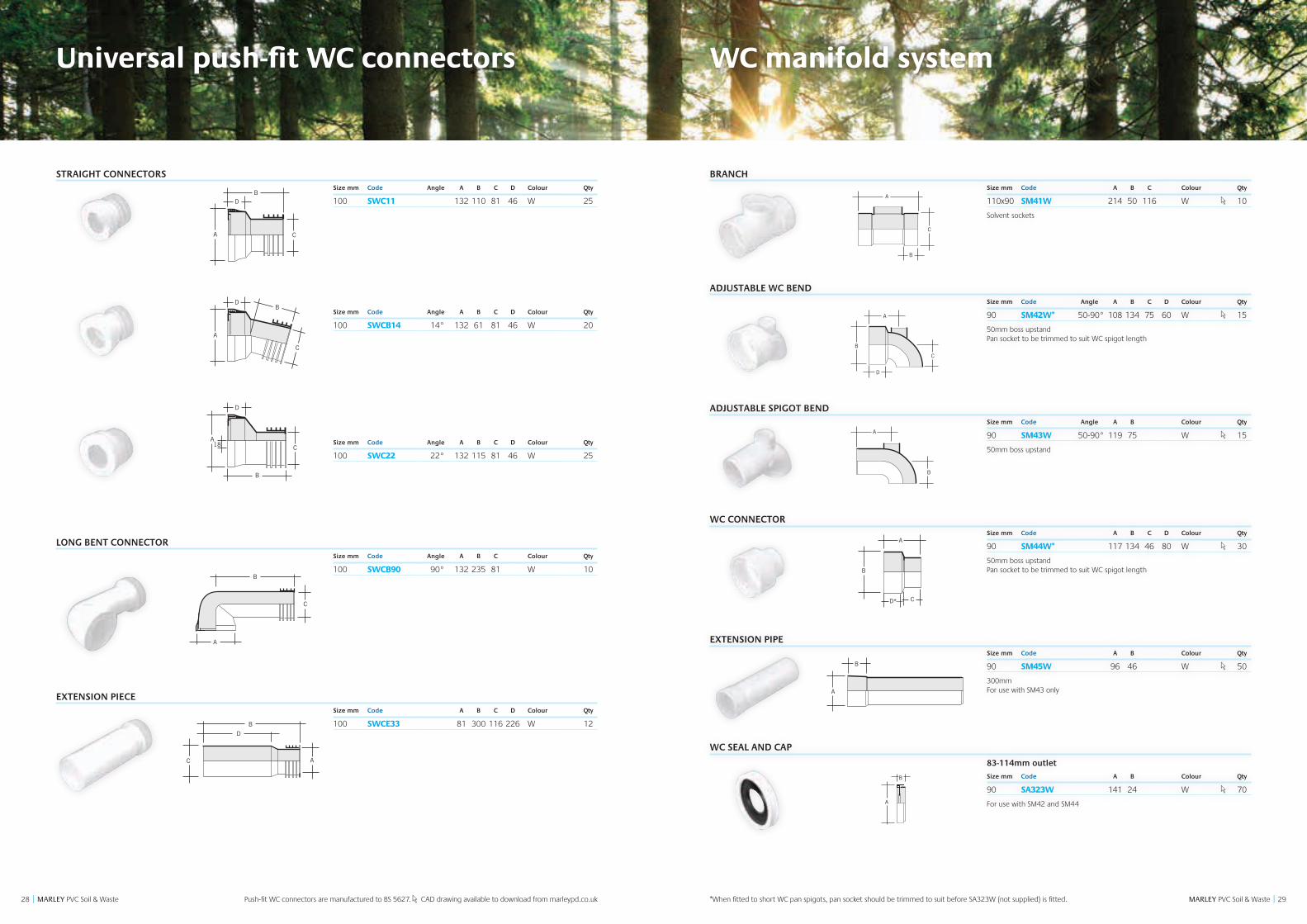
STRAIGHT CONNECTORS Size mm Code Angle A B C D Colour Qty
100 SWC11 132 110 81 46 W 25
Size mm Code Angle A B C D Colour Qty
100 SWCB14 14° 132 61 81 46 W 20
Size mm Code Angle A B C D Colour Qty
100 SWC22 22° 132 115 81 46 W 25
LONG BENT CONNECTOR Size mm Code Angle A B C Colour Qty
100 SWCB90 90° 132 235 81 W 10
EXTENSION PIECE Size mm Code A B C D Colour Qty
100 SWCE33 81 300 116 226 W 12
A
DB
C
A
D
C
B
A
D
B
C18
A
D
B
CE
A
B
C
C
A
B
D
A
DB
C
A
D
C
B
A
D
B
C18
A
D
B
CE
A
B
C
C
A
B
D
A
DB
C
A
D
C
B
A
D
B
C18
A
D
B
CE
A
B
C
C
A
B
D
A
DB
C
A
D
C
B
A
D
B
C18
A
D
B
CE
A
B
CC
A
BD
A
DB
C
A
D
C
B
A
D
B
C18
A
D
B
CE
A
B
CC
A
BD
Push-fit WC connectors are manufactured to BS 5627. CAD drawing available to download from marleypd.co.uk
WC manifold system
BRANCH Size mm Code A B C Colour Qty
110x90 SM41W 214 50 116 W 10
Solvent sockets
ADJUSTABLE WC BEND Size mm Code Angle A B C D Colour Qty
90 SM42W* 50-90° 108 134 75 60 W 15
50mm boss upstand Pan socket to be trimmed to suit WC spigot length
ADJUSTABLE SPIGOT BEND Size mm Code Angle A B Colour Qty
90 SM43W 50-90° 119 75 W 15
50mm boss upstand
WC CONNECTOR Size mm Code A B C D Colour Qty
90 SM44W* 117 134 46 80 W 30
50mm boss upstand Pan socket to be trimmed to suit WC spigot length
EXTENSION PIPE Size mm Code A B Colour Qty
90 SM45W 96 46 W 50
300mm For use with SM43 only
WC SEAL AND CAP
83-114mm outlet
Size mm Code A B Colour Qty
90 SA323W 141 24 W 70
For use with SM42 and SM44
B
C
A
D
C
A
B
A
B
B
C
A
D*
B
A
B
C
A
D
C
A
B
A
B
B
C
A
D*
B
A
B
C
A
D
C
A
B
A
B
B
C
A
D*
B
A
B
C
A
D
C
A
B
A
B
B
C
A
D*
B
A
B
C
A
D
C
A
B
A
B
B
C
A
D*
B
A
C
A
B
C
B
A
B
A
C
B
C
A
D
A
B
C
D
B
A
*When fitted to short WC pan spigots, pan socket should be trimmed to suit before SA323W (not supplied) is fitted.
31
Product range
30 MARLEY PVC Soil & Waste || MARLEY PVC Soil & Waste
Fire protection
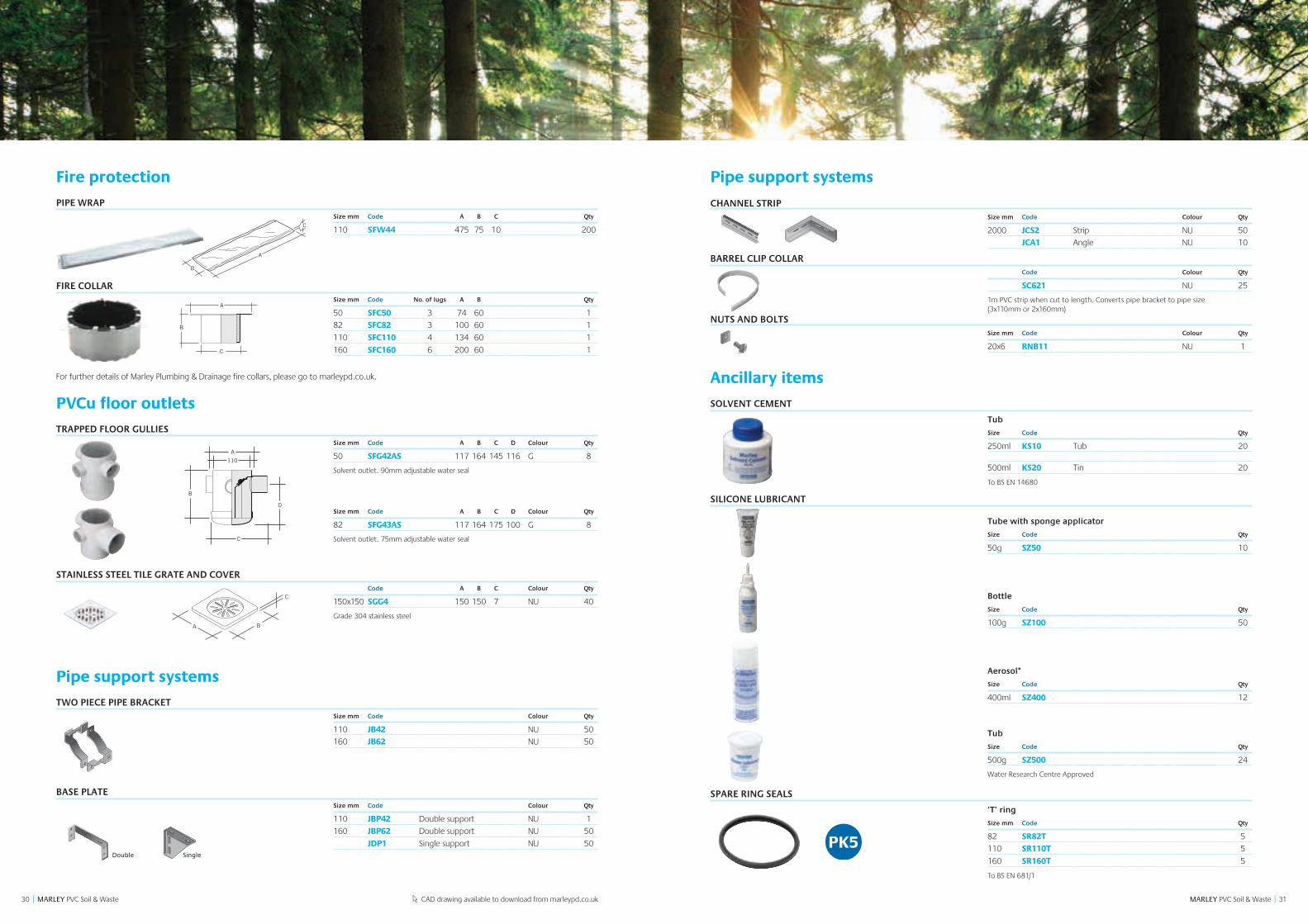
PIPE WRAP Size mm Code A B C Qty
110 SFW44 475 75 10 200
FIRE COLLAR Size mm Code No. of lugs A B Qty
50 SFC50 3 74 60 1
82 SFC82 3 100 60 1
110 SFC110 4 134 60 1
160 SFC160 6 200 60 1
For further details of Marley Plumbing & Drainage fire collars, please go to marleypd.co.uk.
PVCu floor outlets
TRAPPED FLOOR GULLIES Size mm Code A B C D Colour Qty
50 SFG42AS 117 164 145 116 G 8
Solvent outlet. 90mm adjustable water seal
Size mm Code A B C D Colour Qty
82 SFG43AS 117 164 175 100 G 8
Solvent outlet. 75mm adjustable water seal
STAINLESS STEEL TILE GRATE AND COVER Code A B C Colour Qty
150x150 SGG4 150 150 7 NU 40
Grade 304 stainless steel
Pipe support systems
TWO PIECE PIPE BRACKET Size mm Code Colour Qty
110 JB42 NU 50
160 JB62 NU 50
BASE PLATE Size mm Code Colour Qty
110 JBP42 Double support NU 1
160 JBP62 Double support NU 50
JDP1 Single support NU 50
A
B
C
A
B
C
B
A
110
C
D
C
BA
CAD drawing available to download from marleypd.co.uk
Pipe support systems
CHANNEL STRIPSize mm Code Colour Qty
2000 JCS2 Strip NU 50
JCA1 Angle NU 10
BARREL CLIP COLLAR Code Colour Qty
SC621 NU 25
1m PVC strip when cut to length. Converts pipe bracket to pipe size (3x110mm or 2x160mm)
NUTS AND BOLTSSize mm Code Colour Qty
20x6 RNB11 NU 1
Ancillary items
SOLVENT CEMENT
Tub
Size Code Qty
250ml KS10 Tub 20
500ml KS20 Tin 20
To BS EN 14680
SILICONE LUBRICANT
Tube with sponge applicator
Size Code Qty
50g SZ50 10
Bottle
Size Code Qty
100g SZ100 50
Aerosol*
Size Code Qty
400ml SZ400 12
Tub
Size Code Qty
500g SZ500 24
Water Research Centre Approved
SPARE RING SEALS
‘T’ ring
Size mm Code Qty
82 SR82T 5
110 SR110T 5
160 SR160T 5
To BS EN 681/1
Pipe support- Nut/bolt
Pipe support- channel strip
Pipe support- single plate
Pipe support- Channel angle
Soil & vent JB32
Pipe support- D/supp base plate
SingleDouble
3332 MARLEY PVC Soil & Waste || MARLEY PVC Soil & Waste All documentation is available to download from marleypd.co.uk Technical hotline: 01622 852695
Design
L = 450mm up to three storeys high L = 740mm up to five storeys high L = one storey height, over five storeys
UBL488 or 2 – UB455 bends
SWS415/41 boss pipe
L
Secondary ventilated stack
Stack size Secondary vent Maximum capacity (l/s)
(mm) (mm) Swept entries
82 50 3.4
110 50 7.3
160 80 18.3
Primary ventilated stack
Stack size Maximum capacity (l/s)
(mm) Swept entries
82 2.6
110 5.2
160 12.4
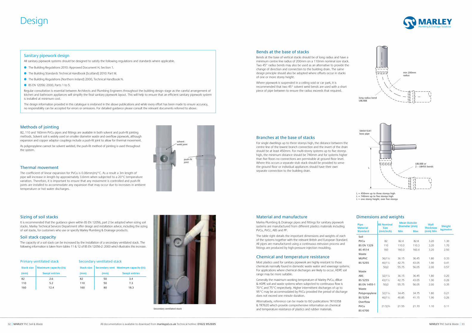
long radius bend UBL488
min 200mm radius
Methods of jointing82, 110 and 160mm PVCu pipes and fittings are available in both solvent and push-fit jointing methods. Solvent soil is widely used on smaller diameter waste and overflow pipework, although expansion and copper adaptor couplings include a push-fit joint to allow for thermal movement.
As polypropylene cannot be solvent welded, the push-fit method of jointing is used throughout the system.
Thermal movementThe coefficient of linear expansion for PVCu is 0.06mm/m/°C. As a result a 3m length of pipe will increase in length by approximately 3.6mm when subjected to a 20°C temperature variation. Therefore, it is important to ensure that any movement is controlled and push-fit joints are installed to accommodate any expansion that may occur due to increases in ambient temperature or hot water discharges.
solvent weld joint
push-fit joint
Bends at the base of stacksBends at the base of vertical stacks should be of long radius and have a minimum centre line radius of 200mm on a 110mm nominal size stack. Two 45° radius bends may also be used as an alternative to provide the change of direction and connection to the building drain. The same design principle should also be adopted where offsets occur in stacks of one or more storey height.
Where pipework is suspended in a ceiling void or car park, it is recommended that two 45° solvent weld bends are used with a short piece of pipe between to ensure the radius exceeds that required.
Sanitary pipework design All sanitary pipework systems should be designed to satisfy the following regulations and standards where applicable.
● The Building Regulations 2010: Approved Document H, Section 1.
● The Building Standards Technical Handbook (Scotland) 2010: Part M.
● The Building Regulations (Northern Ireland) 2000, Technical Handbook N.
● BS EN 12056: 2000, Parts 1 to 5.
Regular consultation is essential between Architects and Plumbing Engineers throughout the building design stage as the careful arrangement of kitchen and bathroom appliances will simplify the final sanitary pipework layout. This will help to ensure that an efficient sanitary pipework system is installed at minimum cost.
The design information provided in this catalogue is endorsed in the above publications and while every effort has been made to ensure accuracy, no responsibility can be accepted for errors or omissions. For detailed guidance please consult the relevant documents referred to above.
Branches at the base of stacksFor single dwellings up to three storeys high, the distance between the centre line of the lowest branch connection and the invert of the drain should be at least 450mm. For multi-storey systems up to five storeys high, the minimum distance should be 740mm and for systems higher than five floors no connections are permissible at ground floor level. Where this occurs a separate stub stack should be provided to serve the ground floor or individual appliances should have their own separate connection to the building drain.
Material and manufactureMarley Plumbing & Drainage pipes and fittings for sanitary pipework systems are manufactured from different plastics materials including PVCu, PVCc, ABS and PP.
The table right details the important dimensions and weights of each of the systems together with the relevant British and European Standard. All pipes are manufactured using a continuous extrusion process and fittings are produced by high-pressure injection moulding.
Chemical and temperature resistanceMost plastics used for sanitary pipework are highly resistant to those chemicals normally found in domestic waste water and sewerage systems. For applications where chemical discharges are likely to occur, HDPE soil range may be more suitable.
Generally the maximum working temperature of Marley PVCu, dBlue & HDPE soil and waste systems when subjected to continuous flow is 70°C and 75°C respectively. Higher intermittent discharges of up to 95°C may be accommodated by PVCu provided the period of discharge does not exceed one minute duration.
Alternatively, reference can be made to ISO publications TR10358 & TR7620 which provide comprehensive information on chemical and temperature resistance of plastics and rubber materials.
Sizing of soil stacksIt is recommended that the guidance given within BS EN 12056, part 2 be adopted when sizing soil stacks. Marley Technical Services Department offer design and installation advice, including the sizing of soil stacks, for customers who use or specify Marley Plumbing & Drainage products.
Soil stack capacity The capacity of a soil stack can be increased by the installation of a secondary ventilated stack. The following information is taken from tables 11 & 12 of BS EN 12056-2: 2000 which illustrates this increase.
Secondary ventilated stack
Dimensions and weights
Pipe Material Standard
BS Nominal Size
(mm/inch)
Mean Outside Diameter (mm)
Wall Thickness (mm) Min
Weight kg/metre
Min Max
Soil
PVCu 82 82.4 82.8 3.20 1.30
BS EN 1329 110 110.0 110.3 3.20 1.70
BS 4514 160 160.0 160.4 3.20 2.50
Waste
MUPVC 36/1¼ 36.15 36.45 1.80 0.33
BS 5255 40/1½ 42.75 43.05 1.90 0.41
50/2 55.75 56.05 2.00 0.57
Waste
ABS 32/1¼ 36.15 36.45 1.80 0.20
BS 5255 43/1½ 42.75 43.05 1.90 0.26
BS EN 1455-1 50/2 55.75 56.05 2.00 0.35
Waste
Polypropylene 32/1¼ 34.45 34.75 1.80 0.21
BS 5254 40/1½ 40.85 41.15 1.90 0.26
Overflow
PVCu 21.5/¾ 21.55 21.70 1.10 0.11
BS 6700
3534 MARLEY PVC Soil & Waste || MARLEY PVC Soil & Waste
Design
All documentation is available to download from marleypd.co.uk Technical hotline: 01622 852695
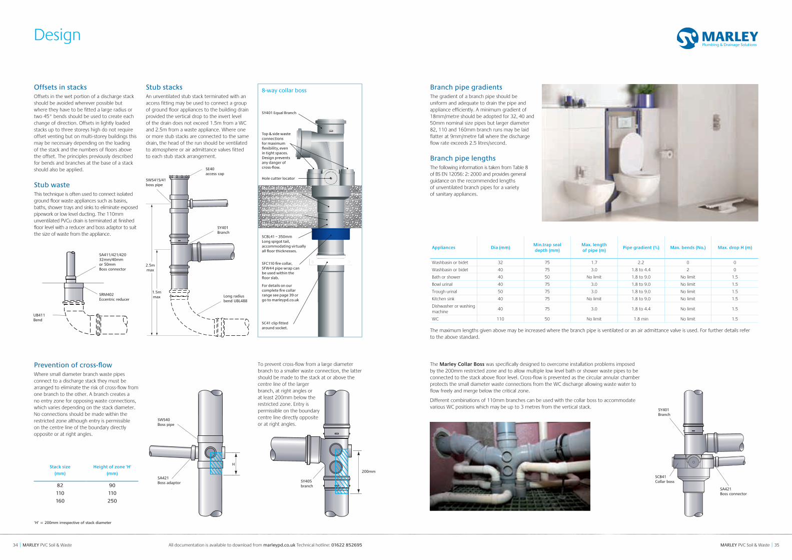
Prevention of cross-flowWhere small diameter branch waste pipes connect to a discharge stack they must be arranged to eliminate the risk of cross-flow from one branch to the other. A branch creates a no entry zone for opposing waste connections, which varies depending on the stack diameter. No connections should be made within the restricted zone although entry is permissible on the centre line of the boundary directly opposite or at right angles.
Offsets in stacksOffsets in the wet portion of a discharge stack should be avoided wherever possible but where they have to be fitted a large radius or two 45° bends should be used to create each change of direction. Offsets in lightly loaded stacks up to three storeys high do not require offset venting but on multi-storey buildings this may be necessary depending on the loading of the stack and the numbers of floors above the offset. The principles previously described for bends and branches at the base of a stack should also be applied.
Stub wasteThis technique is often used to connect isolated ground floor waste appliances such as basins, baths, shower trays and sinks to eliminate exposed pipework or low level ducting. The 110mm unventilated PVCu drain is terminated at finished floor level with a reducer and boss adaptor to suit the size of waste from the appliance.
Stub stacksAn unventilated stub stack terminated with an access fitting may be used to connect a group of ground floor appliances to the building drain provided the vertical drop to the invert level of the drain does not exceed 1.5m from a WC and 2.5m from a waste appliance. Where one or more stub stacks are connected to the same drain, the head of the run should be ventilated to atmosphere or air admittance valves fitted to each stub stack arrangement.
SE40 access cap
SWS415/41boss pipe
SY401Branch
Long radiusbend UBL488
1.5mmax
2.5mmax
SA411/421/42032mm/40mm or 50mm Boss connector
SRM402Eccentric reducer
UB411Bend
‘H’ = 200mm irrespective of stack diameter
Stack size
(mm)
Height of zone 'H'
(mm)
82 90
110 110
160 250
SWS40Boss pipe
SA421Boss adaptor
H
The Marley Collar Boss was specifically designed to overcome installation problems imposed by the 200mm restricted zone and to allow multiple low level bath or shower waste pipes to be connected to the stack above floor level. Cross-flow is prevented as the circular annular chamber protects the small diameter waste connections from the WC discharge allowing waste water to flow freely and merge below the critical zone.
Different combinations of 110mm branches can be used with the collar boss to accommodate various WC positions which may be up to 3 metres from the vertical stack.
Top & side waste connections for maximum flexibility, even in tight spaces. Design prevents any danger of cross-flow.
SY401 Equal Branch
Hole cutter locator
No need for pipe to be cut on site, saving installation time. Comes complete with pre-chamfered spigot tail for easy jointing.
Factory fitted, air tested joint ensuring long term integrity.
SCBL41 – 350mm Long spigot tail, accommodating virtually all floor thicknesses.
SFC110 fire collar, SFW44 pipe wrap can be used within the floor slab.
For details on our complete fire collar range see page 39 or go to marleypd.co.uk
SC41 clip fitted around socket.
61mm
SA421Boss connector
SY401Branch
SCB41Collar boss
8-way collar boss
To prevent cross-flow from a large diameter branch to a smaller waste connection, the latter should be made to the stack at or above the centre line of the larger branch, at right angles or at least 200mm below the restricted zone. Entry is permissible on the boundary centre line directly opposite or at right angles.
SY405branch
200mm
Branch pipe gradientsThe gradient of a branch pipe should be uniform and adequate to drain the pipe and appliance efficiently. A minimum gradient of 18mm/metre should be adopted for 32, 40 and 50mm nominal size pipes but larger diameter 82, 110 and 160mm branch runs may be laid flatter at 9mm/metre fall where the discharge flow rate exceeds 2.5 litres/second.
Branch pipe lengthsThe following information is taken from Table 8 of BS EN 12056: 2: 2000 and provides general guidance on the recommended lengths of unventilated branch pipes for a variety of sanitary appliances.
Appliances Dia (mm)Min.trap seal depth (mm)
Max. length of pipe (m)
Pipe gradient (%) Max. bends (No.) Max. drop H (m)
Washbasin or bidet 32 75 1.7 2.2 0 0
Washbasin or bidet 40 75 3.0 1.8 to 4.4 2 0
Bath or shower 40 50 No limit 1.8 to 9.0 No limit 1.5
Bowl urinal 40 75 3.0 1.8 to 9.0 No limit 1.5
Trough urinal 50 75 3.0 1.8 to 9.0 No limit 1.5
Kitchen sink 40 75 No limit 1.8 to 9.0 No limit 1.5
Dishwasher or washing machine
40 75 3.0 1.8 to 4.4 No limit 1.5
WC 110 50 No limit 1.8 min No limit 1.5
The maximum lengths given above may be increased where the branch pipe is ventilated or an air admittance valve is used. For further details refer to the above standard.
3736 MARLEY PVC Soil & Waste || MARLEY PVC Soil & Waste
Design
All documentation is available to download from marleypd.co.uk Technical hotline: 01622 852695
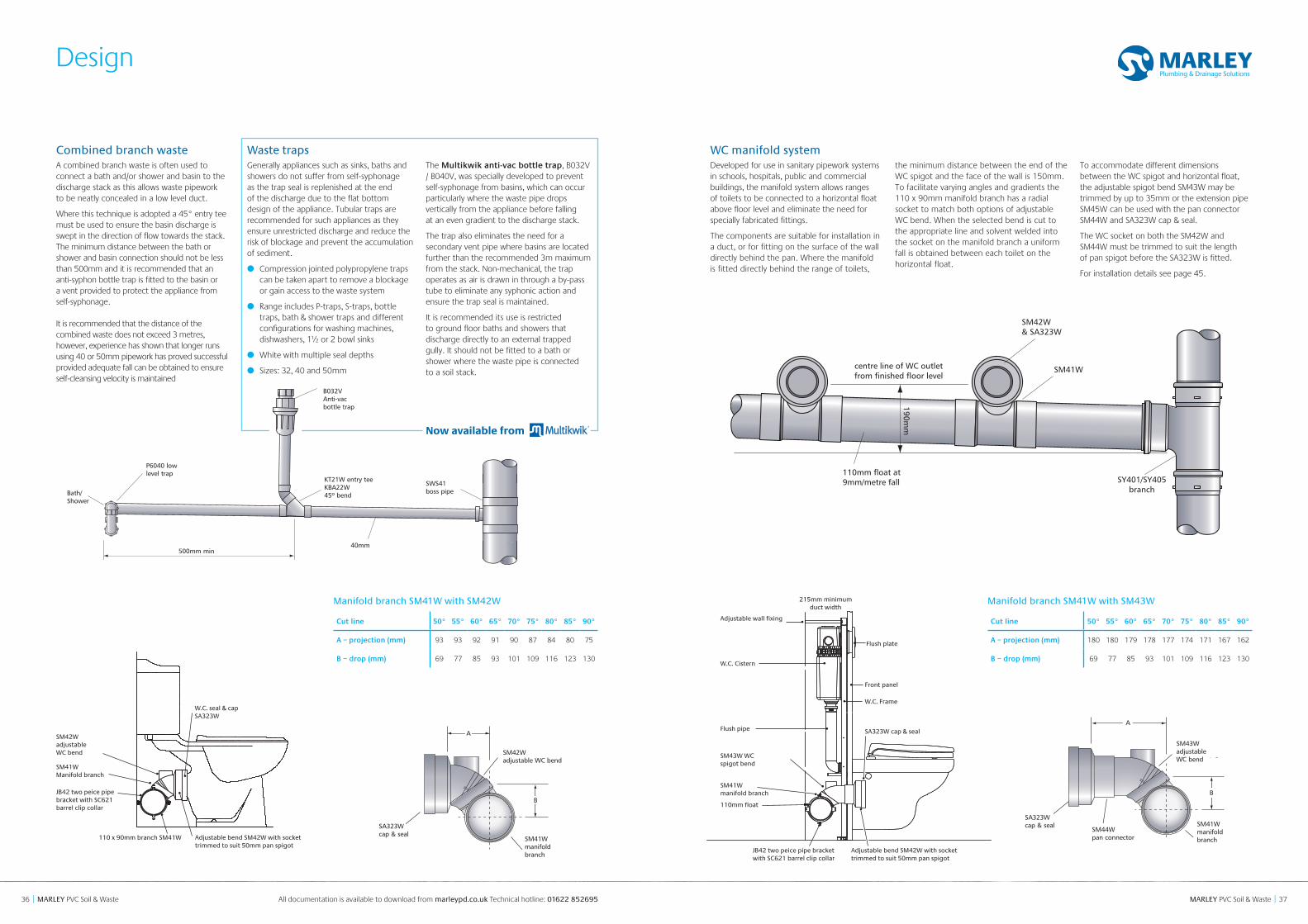
WC manifold systemDeveloped for use in sanitary pipework systems in schools, hospitals, public and commercial buildings, the manifold system allows ranges of toilets to be connected to a horizontal float above floor level and eliminate the need for specially fabricated fittings.
The components are suitable for installation in a duct, or for fitting on the surface of the wall directly behind the pan. Where the manifold is fitted directly behind the range of toilets,
the minimum distance between the end of the WC spigot and the face of the wall is 150mm. To facilitate varying angles and gradients the 110 x 90mm manifold branch has a radial socket to match both options of adjustable WC bend. When the selected bend is cut to the appropriate line and solvent welded into the socket on the manifold branch a uniform fall is obtained between each toilet on the horizontal float.
To accommodate different dimensions between the WC spigot and horizontal float, the adjustable spigot bend SM43W may be trimmed by up to 35mm or the extension pipe SM45W can be used with the pan connector SM44W and SA323W cap & seal.
The WC socket on both the SM42W and SM44W must be trimmed to suit the length of pan spigot before the SA323W is fitted.
For installation details see page 45. A
B
SA323Wcap & seal
SM41Wmanifold branch
SM42Wadjustable bend
SM42W& SA323W
SM41W
SY401/SY405branch
110mm float at9mm/metre fall
centre line of WC outletfrom finished floor level
190mm
Manifold branch SM41W with SM43W
Cut line 50° 55° 60° 65° 70° 75° 80° 85° 90°
A – projection (mm) 180 180 179 178 177 174 171 167 162
B – drop (mm) 69 77 85 93 101 109 116 123 130
Manifold branch SM41W with SM42W
Cut line 50° 55° 60° 65° 70° 75° 80° 85° 90°
A – projection (mm) 93 93 92 91 90 87 84 80 75
B – drop (mm) 69 77 85 93 101 109 116 123 130
35303530
pan connectorSM44W
manifold branchSM41W
manifold branch
adjustable spigot bendSM43W
adjustable bendSM42W
cap & sealSA323W
cap & sealSA323W
SM41W
B
B
A
A
SM41W manifold branch
SA323W cap & seal
SM42W adjustable WC bend
35303530
pan connectorSM44W
manifold branchSM41W
manifold branch
adjustable spigot bendSM43W
adjustable bendSM42W
cap & sealSA323W
cap & sealSA323W
SM41W
B
B
A
A
SM41W manifold branch
SM44W pan connector
SA323W cap & seal
SM43W adjustable WC bend
A
B
A
B
Adjustable wall fixing
215mm minimum duct width
W.C. Cistern
Flush plate
W.C. Frame
Front panel
SA323W cap & sealFlush pipe
SM43W WC spigot bend
SM41W manifold branch
110mm float
JB42 two peice pipe bracket with SC621 barrel clip collar
SM41W Manifold branch
SM42W adjustable WC bend
W.C. seal & cap SA323W
JB42 two peice pipe bracket with SC621 barrel clip collar
110 x 90mm branch SM41W Adjustable bend SM42W with socket trimmed to suit 50mm pan spigot
Adjustable bend SM42W with socket trimmed to suit 50mm pan spigot
Combined branch wasteA combined branch waste is often used to connect a bath and/or shower and basin to the discharge stack as this allows waste pipework to be neatly concealed in a low level duct.
Where this technique is adopted a 45° entry tee must be used to ensure the basin discharge is swept in the direction of flow towards the stack. The minimum distance between the bath or shower and basin connection should not be less than 500mm and it is recommended that an anti-syphon bottle trap is fitted to the basin or a vent provided to protect the appliance from self-syphonage.
It is recommended that the distance of the combined waste does not exceed 3 metres, however, experience has shown that longer runs using 40 or 50mm pipework has proved successful provided adequate fall can be obtained to ensure self-cleansing velocity is maintained
Now available from
Waste trapsGenerally appliances such as sinks, baths and showers do not suffer from self-syphonage as the trap seal is replenished at the end of the discharge due to the flat bottom design of the appliance. Tubular traps are recommended for such appliances as they ensure unrestricted discharge and reduce the risk of blockage and prevent the accumulation of sediment.
● Compression jointed polypropylene traps can be taken apart to remove a blockage or gain access to the waste system
● Range includes P-traps, S-traps, bottle traps, bath & shower traps and different configurations for washing machines, dishwashers, 1½ or 2 bowl sinks
● White with multiple seal depths
● Sizes: 32, 40 and 50mm
The Multikwik anti-vac bottle trap, B032V / B040V, was specially developed to prevent self-syphonage from basins, which can occur particularly where the waste pipe drops vertically from the appliance before falling at an even gradient to the discharge stack.
The trap also eliminates the need for a secondary vent pipe where basins are located further than the recommended 3m maximum from the stack. Non-mechanical, the trap operates as air is drawn in through a by-pass tube to eliminate any syphonic action and ensure the trap seal is maintained.
It is recommended its use is restricted to ground floor baths and showers that discharge directly to an external trapped gully. It should not be fitted to a bath or shower where the waste pipe is connected to a soil stack.
P6040 lowlevel trap
Bath/Shower
B032VAnti-vacbottle trap
KT21W entry teeKBA22W 45º bend
SWS41boss pipe
500mm min40mm
3938 MARLEY PVC Soil & Waste || MARLEY PVC Soil & Waste
Design
All documentation is available to download from marleypd.co.uk Technical hotline: 01622 852695
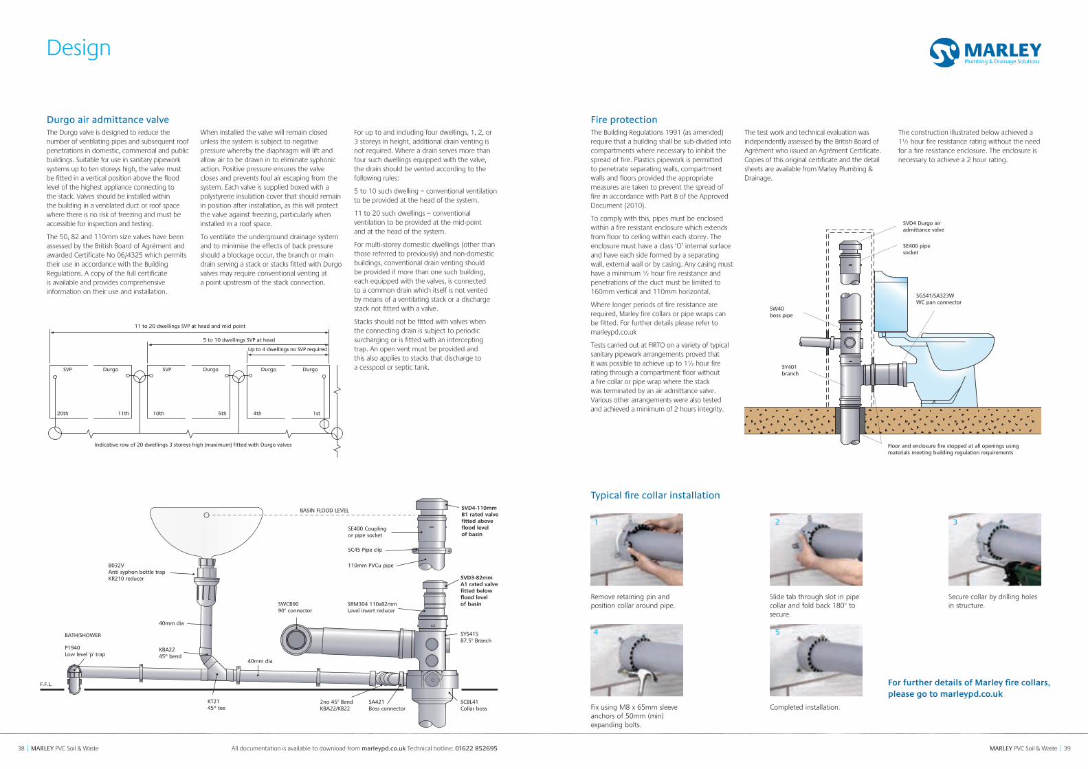
Durgo air admittance valveThe Durgo valve is designed to reduce the number of ventilating pipes and subsequent roof penetrations in domestic, commercial and public buildings. Suitable for use in sanitary pipework systems up to ten storeys high, the valve must be fitted in a vertical position above the flood level of the highest appliance connecting to the stack. Valves should be installed within the building in a ventilated duct or roof space where there is no risk of freezing and must be accessible for inspection and testing.
The 50, 82 and 110mm size valves have been assessed by the British Board of Agrément and awarded Certificate No 06/4325 which permits their use in accordance with the Building Regulations. A copy of the full certificate is available and provides comprehensive information on their use and installation.
When installed the valve will remain closed unless the system is subject to negative pressure whereby the diaphragm will lift and allow air to be drawn in to eliminate syphonic action. Positive pressure ensures the valve closes and prevents foul air escaping from the system. Each valve is supplied boxed with a polystyrene insulation cover that should remain in position after installation, as this will protect the valve against freezing, particularly when installed in a roof space.
To ventilate the underground drainage system and to minimise the effects of back pressure should a blockage occur, the branch or main drain serving a stack or stacks fitted with Durgo valves may require conventional venting at a point upstream of the stack connection.
For up to and including four dwellings, 1, 2, or 3 storeys in height, additional drain venting is not required. Where a drain serves more than four such dwellings equipped with the valve, the drain should be vented according to the following rules:
5 to 10 such dwelling – conventional ventilation to be provided at the head of the system.
11 to 20 such dwellings – conventional ventilation to be provided at the mid-point and at the head of the system.
For multi-storey domestic dwellings (other than those referred to previously) and non-domestic buildings, conventional drain venting should be provided if more than one such building, each equipped with the valves, is connected to a common drain which itself is not vented by means of a ventilating stack or a discharge stack not fitted with a valve.
Stacks should not be fitted with valves when the connecting drain is subject to periodic surcharging or is fitted with an intercepting trap. An open vent must be provided and this also applies to stacks that discharge to a cesspool or septic tank.
SYS415 87.5° Branch
SRM304 110x82mm Level invert reducer
SE400 Coupling or pipe socket
BASIN FLOOD LEVEL
BATH/SHOWER
F.F.L.
SC45 Pipe clip
110mm PVCu pipeB032VAnti syphon bottle trap KR210 reducer
KBA2245º bend
40mm dia
40mm dia
P1940Low level 'p' trap
SWCB9090° connector
KT2145º tee
SCBL41Collar boss
SA421 Boss connector
2no 45° Bend KBA22/KB22
20th
SVP SVP DurgoDurgo Durgo Durgo
Up to 4 dwellings no SVP required
5 to 10 dwellings SVP at head
11 to 20 dwellings SVP at head and mid point
11th 10th 5th 4th 1st
Indicative row of 20 dwellings 3 storeys high (maximum) fitted with Durgo valves
Fire protectionThe Building Regulations 1991 (as amended) require that a building shall be sub-divided into compartments where necessary to inhibit the spread of fire. Plastics pipework is permitted to penetrate separating walls, compartment walls and floors provided the appropriate measures are taken to prevent the spread of fire in accordance with Part B of the Approved Document (2010).
To comply with this, pipes must be enclosed within a fire resistant enclosure which extends from floor to ceiling within each storey. The enclosure must have a class ‘O’ internal surface and have each side formed by a separating wall, external wall or by casing. Any casing must have a minimum ½ hour fire resistance and penetrations of the duct must be limited to 160mm vertical and 110mm horizontal.
Where longer periods of fire resistance are required, Marley fire collars or pipe wraps can be fitted. For further details please refer to marleypd.co.uk
Tests carried out at FIRTO on a variety of typical sanitary pipework arrangements proved that it was possible to achieve up to 1½ hour fire rating through a compartment floor without a fire collar or pipe wrap where the stack was terminated by an air admittance valve. Various other arrangements were also tested and achieved a minimum of 2 hours integrity.
The test work and technical evaluation was independently assessed by the British Board of Agrément who issued an Agrément Certificate. Copies of this original certificate and the detail sheets are available from Marley Plumbing & Drainage.
The construction illustrated below achieved a 1½ hour fire resistance rating without the need for a fire resistance enclosure. The enclosure is necessary to achieve a 2 hour rating.
SW40boss pipe
SY401branch
SVD4 Durgo airadmittance valve
SGS41/SA323WWC pan connector
Floor and enclosure fire stopped at all openings using materials meeting building regulation requirements
SE400 pipesocket
Typical fire collar installation
For further details of Marley fire collars, please go to marleypd.co.uk
SVD4-110mm B1 rated valve fitted above flood level of basin
SVD3-82mm A1 rated valve fitted below flood level of basin
Remove retaining pin and position collar around pipe.
Slide tab through slot in pipe collar and fold back 180° to secure.
Secure collar by drilling holes in structure.
Fix using M8 x 65mm sleeve anchors of 50mm (min) expanding bolts.
Completed installation.
1 2 3
4 5
4140 MARLEY PVC Soil & Waste || MARLEY PVC Soil & Waste
Installation data
All documentation is available to download from marleypd.co.uk Technical hotline: 01622 852695
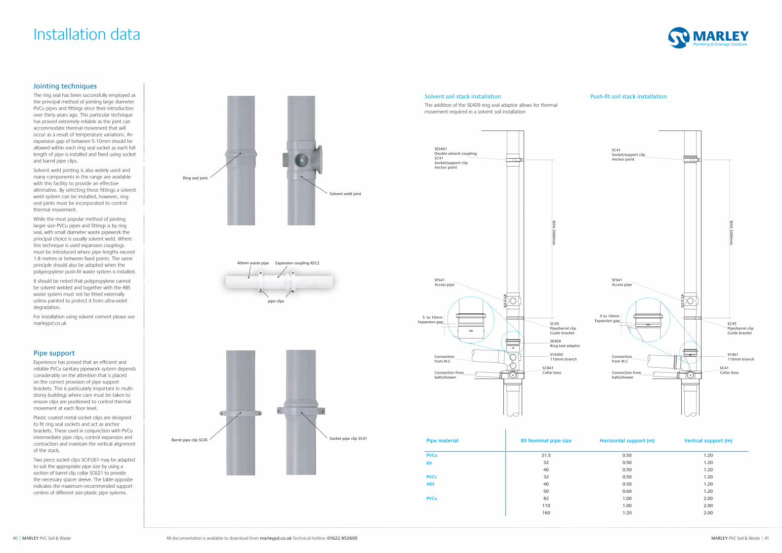
Jointing techniquesThe ring seal has been successfully employed as the principal method of jointing large diameter PVCu pipes and fittings since their introduction over thirty years ago. This particular technique has proved extremely reliable as the joint can accommodate thermal movement that will occur as a result of temperature variations. An expansion gap of between 5-10mm should be allowed within each ring seal socket as each full length of pipe is installed and fixed using socket and barrel pipe clips.
Solvent weld jointing is also widely used and many components in the range are available with this facility to provide an effective alternative. By selecting these fittings a solvent weld system can be installed, however, ring seal joints must be incorporated to control thermal movement.
While the most popular method of jointing larger size PVCu pipes and fittings is by ring seal, with small diameter waste pipework the principal choice is usually solvent weld. Where this technique is used expansion couplings must be introduced where pipe lengths exceed 1.8 metres or between fixed points. The same principle should also be adopted when the polypropylene push-fit waste system is installed.
It should be noted that polypropylene cannot be solvent welded and together with the ABS waste system must not be fitted externally unless painted to protect it from ultra-violet degradation.
For installation using solvent cement please see marleypd.co.uk
Pipe supportExperience has proved that an efficient and reliable PVCu sanitary pipework system depends considerably on the attention that is placed on the correct provision of pipe support brackets. This is particularly important in multi-storey buildings where care must be taken to ensure clips are positioned to control thermal movement at each floor level.
Plastic coated metal socket clips are designed to fit ring seal sockets and act as anchor brackets. These used in conjunction with PVCu intermediate pipe clips, control expansion and contraction and maintain the vertical alignment of the stack.
Two piece socket clips SC41/61 may be adapted to suit the appropriate pipe size by using a section of barrel clip collar SC621 to provide the necessary spacer sleeve. The table opposite indicates the maximum recommended support centres of different size plastic pipe systems.
Pipe material BS Nominal pipe size Horizontal support (m) Vertical support (m)
PVCu 21.5 0.50 1.20
pp 32 0.50 1.20
40 0.50 1.20
PVCc 32 0.50 1.20
ABS 40 0.50 1.20
50 0.60 1.20
PVCu 82 1.00 2.00
110 1.00 2.00
160 1.20 2.00
Ring seal joint
Solvent weld joint
Expansion coupling KEC2
pipe clips
40mm waste pipe
Barrel pipe clip SC45 Socket pipe clip SC41
SES401Double solvent couplingSC41Socket/support clipAnchor point
SC45Pipe/barrel clipGuide bracket
SFS41Access pipe
SYS405110mm branch
Connectionfrom W.C
Connection frombath/shower
SCB41Collar boss
SE409Ring seal adaptor
SC41Socket/support clipAnchor point
SC45Pipe/barrel clipGuide bracket
SFS41Access pipe
SY401110mm branch
Connectionfrom W.C
Connection frombath/shower
SC41Collar boss
MA
X 2
00
0m
m
MA
X 2
00
0m
m
5 to 10mmExpansion gap
5 to 10mm Expansion gap
Solvent soil stack installation
The addition of the SE409 ring seal adaptor allows for thermal movement required in a solvent soil installation
Push-fit soil stack installation
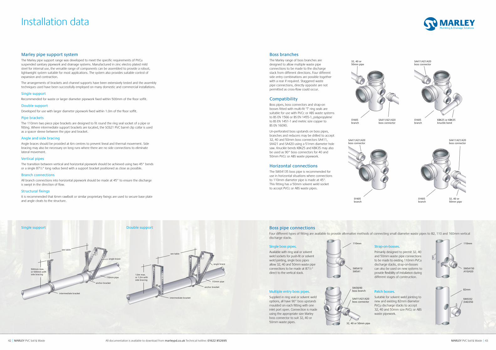
4342 MARLEY PVC Soil & Waste || MARLEY PVC Soil & Waste
Installation data
All documentation is available to download from marleypd.co.uk Technical hotline: 01622 852695
Marley pipe support systemThe Marley pipe support range was developed to meet the specific requirements of PVCu suspended sanitary pipework and drainage systems. Manufactured in zinc electro plated mild steel for internal use, the versatile range of components can be assembled to provide a robust, lightweight system suitable for most applications. The system also provides suitable control of expansion and contraction.
The arrangements of brackets and channel supports have been extensively tested and the assembly techniques used have been successfully employed on many domestic and commercial installations.
Single support
Recommended for waste or larger diameter pipework fixed within 500mm of the floor soffit.
Double support
Developed for use with larger diameter pipework fixed within 1.0m of the floor soffit.
Pipe brackets
The 110mm two piece pipe brackets are designed to fit round the ring seal socket of a pipe or fitting. Where intermediate support brackets are located, the SC621 PVC barrel clip collar is used as a spacer sleeve between the pipe and bracket.
Angle and side bracing
Angle braces should be provided at 6m centres to prevent lineal and thermal movement. Side bracing may also be necessary on long runs where there are no side connections to eliminate lateral movement.
Vertical pipes
The transition between vertical and horizontal pipework should be achieved using two 45° bends or a single 87½° long radius bend with a support bracket positioned as close as possible.
Branch connections
All branch connections into horizontal pipework should be made at 45° to ensure the discharge is swept in the direction of flow.
Structural fixings
It is recommended that 6mm rawlbolt or similar proprietary fixings are used to secure base plate and angle cleats to the structure.
Double supportSingle support
500mm max.or 600mm withside bracing
anchor bracket
angle brace
intermediate bracket
anchor bracket
1.0m
750mm max.or 1.0m withside bracing
1.2m max.
anchor bracket
angle brace
intermediate bracket
intermediatebracket
1.0m max. or 1.2m withside bracing
angle brace
see table
110mm pipe
110mm pipe
110mm pipe
see table
Single boss pipes.
Available with ring seal or solvent weld sockets for push-fit or solvent weld jointing, single boss pipes allow 32, 40 and 50mm waste pipe connections to be made at 87½° direct to the vertical stack.
Strap-on-bosses.
Primarily designed to permit 32, 40 and 50mm waste pipe connections to be made to existing 110mm PVCu discharge stacks, strap-on-bosses can also be used on new systems to provide flexibility of installation during different stages of construction.
Multiple entry boss pipes.
Supplied in ring seal or solvent weld options, all have 90° boss upstands moulded on each fitting with one inlet port open. Connection is made using the appropriate size Marley boss connector to suit 32, 40 or 50mm waste pipes.
Patch bosses.
Suitable for solvent weld jointing to new and existing 82mm diameter PVCu discharge stacks to accept 32, 40 and 50mm size PVCc or ABS waste pipework.
Boss pipe connectionsFour different types of fitting are available to provide alternative methods of connecting small diameter waste pipes to 82, 110 and 160mm vertical discharge stacks.
110mm
SWS415/ SWS41
110mm
SWS4150 /410/420
82mm
SWS332 /340/350
SW30/40 boss branch
SA411/421/420 boss connector
32, 40 or 50mm pipe
SA411/421/420 boss connector
32, 40 or 50mm pipe
SY405 branch
SA411/421/420 boss connector
SY405 branch
KBK25 or KBK35 knuckle bend
SA411/421/420 boss connector
SY405 branch
SA411/421/420 boss connector
SY405 branch
32, 40 or 50mm pipe
Boss branchesThe Marley range of boss branches are designed to allow multiple waste pipe connections to be made to the discharge stack from different directions. Four different side entry combinations are possible together with a rear if required. Staggered waste pipe connections, directly opposite are not permitted as cross-flow could occur.
CompatibilityBoss pipes, boss connectors and strap-on bosses fitted with multi-fit ‘T’ ring seals are suitable for use with PVCc or ABS waste systems to BS EN 1566 or BS EN 1455-1, polypropylene to BS EN 1451-1 and metric size copper to BS EN 16090.
Un-perforated boss upstands on boss pipes, branches and reducers may be drilled to accept 32, 40 and 50mm boss connectors SA411, SA421 and SA420 using a 51mm diameter hole saw. Knuckle bends KBK25 and KBK35 may also be used as 90° boss connectors for 40 and 50mm PVCc or ABS waste pipework.
Horizontal connectionsThe SWS4135 boss pipe is recommended for use in horizontal situations where connections to 110mm diameter pipe is made at 45°. This fitting has a 50mm solvent weld socket to accept PVCc or ABS waste pipes.
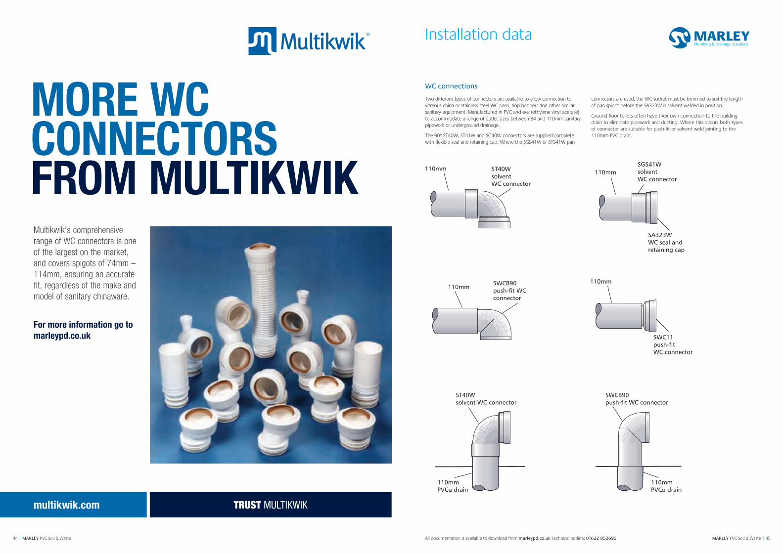
45MARLEY PVC Soil & Waste || MARLEY PVC Soil & Waste All documentation is available to download from marleypd.co.uk Technical hotline: 01622 852695
Installation data
44
ST40W solvent WC connector
SWCB90push-fit WC connector
110mmPVCu drain
110mmPVCu drain
ST40WsolventWC connector
SWCB90push-fit WC connector
110mm 110mm
SGS41WsolventWC connector
SA323WWC seal andretaining cap
SWC11push-fitWC connector
110mm 110mm
ST40W solvent WC connector
SWCB90push-fit WC connector
110mmPVCu drain
110mmPVCu drain
ST40WsolventWC connector
SWCB90push-fit WC connector
110mm 110mm
SGS41WsolventWC connector
SA323WWC seal andretaining cap
SWC11push-fitWC connector
110mm 110mm
ST40W solvent WC connector
SWCB90push-fit WC connector
110mmPVCu drain
110mmPVCu drain
ST40WsolventWC connector
SWCB90push-fit WC connector
110mm 110mm
SGS41WsolventWC connector
SA323WWC seal andretaining cap
SWC11push-fitWC connector
110mm 110mm
ST40W solvent WC connector
SWCB90push-fit WC connector
110mmPVCu drain
110mmPVCu drain
ST40WsolventWC connector
SWCB90push-fit WC connector
110mm 110mm
SGS41WsolventWC connector
SA323WWC seal andretaining cap
SWC11push-fitWC connector
110mm 110mm
ST40W solvent WC connector
SWCB90push-fit WC connector
110mmPVCu drain
110mmPVCu drain
ST40WsolventWC connector
SWCB90push-fit WC connector
110mm 110mm
SGS41WsolventWC connector
SA323WWC seal andretaining cap
SWC11push-fitWC connector
110mm 110mm
ST40W solvent WC connector
SWCB90push-fit WC connector
110mmPVCu drain
110mmPVCu drain
ST40WsolventWC connector
SWCB90push-fit WC connector
110mm 110mm
SGS41WsolventWC connector
SA323WWC seal andretaining cap
SWC11push-fitWC connector
110mm 110mm
WC connections
Two different types of connectors are available to allow connection to vitreous china or stainless steel WC pans, slop hoppers and other similar sanitary equipment. Manufactured in PVC and eva (ethylene vinyl acetate) to accommodate a range of outlet sizes between 84 and 110mm sanitary pipework or underground drainage.
The 90º ST40W, ST41W and SG40W connectors are supplied complete with flexible seal and retaining cap. Where the SGS41W or STS41W pan
connectors are used, the WC socket must be trimmed to suit the length of pan spigot before the SA323W is solvent welded in position.
Ground floor toilets often have their own connection to the building drain to eliminate pipework and ducting. Where this occurs both types of connector are suitable for push-fit or solvent weld jointing to the 110mm PVC drain.
Multikwik's comprehensive range of WC connectors is one of the largest on the market, and covers spigots of 74mm – 114mm, ensuring an accurate fit, regardless of the make and model of sanitary chinaware.
multikwik.com
MORE WCCONNECTORS FROM MULTIKWIK
For more information go to marleypd.co.uk
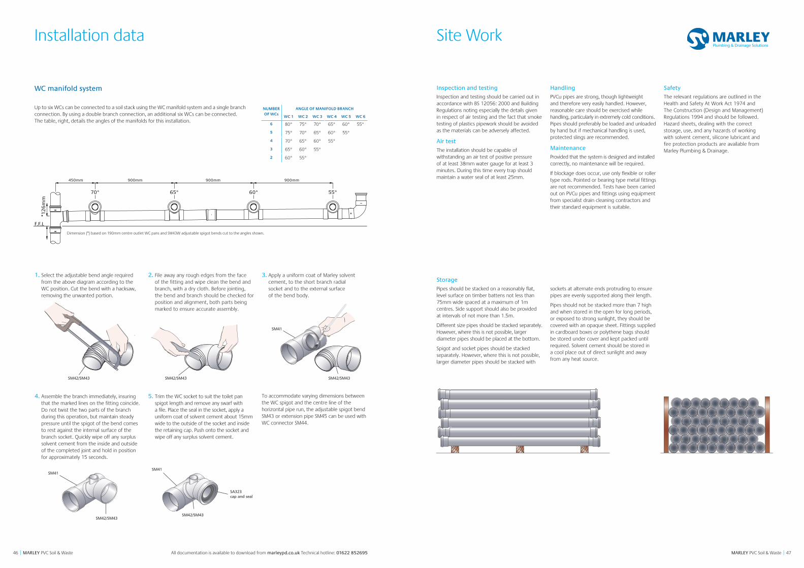
4746 MARLEY PVC Soil & Waste || MARLEY PVC Soil & Waste All documentation is available to download from marleypd.co.uk Technical hotline: 01622 852695
Site WorkInstallation data
Inspection and testing
Inspection and testing should be carried out in accordance with BS 12056: 2000 and Building Regulations noting especially the details given in respect of air testing and the fact that smoke testing of plastics pipework should be avoided as the materials can be adversely affected.
Air test
The installation should be capable of withstanding an air test of positive pressure of at least 38mm water gauge for at least 3 minutes. During this time every trap should maintain a water seal of at least 25mm.
Handling
PVCu pipes are strong, though lightweight and therefore very easily handled. However, reasonable care should be exercised while handling, particularly in extremely cold conditions. Pipes should preferably be loaded and unloaded by hand but if mechanical handling is used, protected slings are recommended.
Maintenance
Provided that the system is designed and installed correctly, no maintenance will be required.
If blockage does occur, use only flexible or roller type rods. Pointed or bearing type metal fittings are not recommended. Tests have been carried out on PVCu pipes and fittings using equipment from specialist drain cleaning contractors and their standard equipment is suitable.
Safety
The relevant regulations are outlined in the Health and Safety At Work Act 1974 and The Construction (Design and Management) Regulations 1994 and should be followed. Hazard sheets, dealing with the correct storage, use, and any hazards of working with solvent cement, silicone lubricant and fire protection products are available from Marley Plumbing & Drainage.
Storage
Pipes should be stacked on a reasonably flat, level surface on timber battens not less than 75mm wide spaced at a maximum of 1m centres. Side support should also be provided at intervals of not more than 1.5m.
Different size pipes should be stacked separately. However, where this is not possible, larger diameter pipes should be placed at the bottom.
Spigot and socket pipes should be stacked separately. However, where this is not possible, larger diameter pipes should be stacked with
sockets at alternate ends protruding to ensure pipes are evenly supported along their length.
Pipes should not be stacked more than 7 high and when stored in the open for long periods, or exposed to strong sunlight, they should be covered with an opaque sheet. Fittings supplied in cardboard boxes or polythene bags should be stored under cover and kept packed until required. Solvent cement should be stored in a cool place out of direct sunlight and away from any heat source.
Up to six WCs can be connected to a soil stack using the WC manifold system and a single branch connection. By using a double branch connection, an additional six WCs can be connected. The table, right, details the angles of the manifolds for this installation.
NUMBER OF WCs
ANGLE OF MANIFOLD BRANCH
WC 1 WC 2 WC 3 WC 4 WC 5 WC 6
6 80° 75° 70° 65° 60° 55°
5 75° 70° 65° 60° 55°
4 70° 65° 60° 55°
3 65° 60° 55°
2 60° 55°
Dimension (*) based on 190mm centre outlet WC pans and SM43W adjustable spigot bends cut to the angles shown.
450mm
70° 65° 60° 55°
900mm 900mm 900mm
*12
6m
m
F.F.L
WC manifold system
4. Assemble the branch immediately, insuring that the marked lines on the fitting coincide. Do not twist the two parts of the branch during this operation, but maintain steady pressure until the spigot of the bend comes to rest against the internal surface of the branch socket. Quickly wipe off any surplus solvent cement from the inside and outside of the completed joint and hold in position for approximately 15 seconds.
5. Trim the WC socket to suit the toilet pan spigot length and remove any swarf with a file. Place the seal in the socket, apply a uniform coat of solvent cement about 15mm wide to the outside of the socket and inside the retaining cap. Push onto the socket and wipe off any surplus solvent cement.
To accommodate varying dimensions between the WC spigot and the centre line of the horizontal pipe run, the adjustable spigot bend SM43 or extension pipe SM45 can be used with WC connector SM44.
SM41
SM42/SM43
SM41
SA323 cap and seal
SM42/SM43
1. Select the adjustable bend angle required from the above diagram according to the WC position. Cut the bend with a hacksaw, removing the unwanted portion.
2. File away any rough edges from the face of the fitting and wipe clean the bend and branch, with a dry cloth. Before jointing, the bend and branch should be checked for position and alignment, both parts being marked to ensure accurate assembly.
3. Apply a uniform coat of Marley solvent cement, to the short branch radial socket and to the external surface of the bend body.
SM42/SM43 SM42/SM43 SM42/SM43
SM41
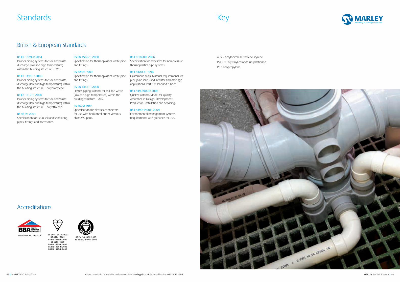
4948 MARLEY PVC Soil & Waste || MARLEY PVC Soil & Waste
Standards
Certificate No. 06/4325BS EN ISO 9001: 2008
BS EN ISO 14001: 2004
BS EN 1329-1 : 2000 BS 4514 : 2001
BS EN 1566-1: 2000 BS 5255: 1989
BS EN 1455-1: 2000 BS EN 1451-1: 2000 BS EN 1519-1: 2000
CERTI
FIED
TOWATER INDUSTRYSPECIFICATION
Accreditations
British & European Standards
BS EN 1329-1: 2014 Plastics piping systems for soil and waste discharge (low and high temperature) within the building structure – PVCu.
BS EN 1451-1: 2000 Plastics piping systems for soil and waste discharge (low and high temperature) within the building structure – polypropylene.
BS EN 1519-1: 2000 Plastics piping systems for soil and waste discharge (low and high temperature) within the building structure – polyethylene.
BS 4514: 2001 Specification for PVCu soil and ventilating pipes, fittings and accessories.
BS EN 1566-1: 2000 Specification for thermoplastics waste pipe and fittings.
BS 5255: 1989 Specification for thermoplastics waste pipe and fittings.
BS EN 1455-1: 2000 Plastics piping systems for soil and waste (low and high temperature) within the building structure – ABS.
BS 5627: 1984 Specification for plastics connectors for use with horizontal outlet vitreous china WC pans.
BS EN 14680: 2006 Specification for adhesives for non-pressure thermoplastics pipe systems.
BS EN 681-1: 1996 Elastomeric seals. Material requirements for pipe joint seals used in water and drainage applications. Part 1 vulcanised rubber.
BS EN ISO 9001: 2008 Quality systems. Model for Quality Assurance in Design, Development, Production, Installation and Servicing.
BS EN ISO 14001: 2004 Environmental management systems. Requirements with guidance for use.
All documentation is available to download from marleypd.co.uk Technical hotline: 01622 852695
ABS = Acrylonitrile butadiene styrene
PVCu = Poly vinyl chloride un-plasticised
PP = Polypropylene
Key
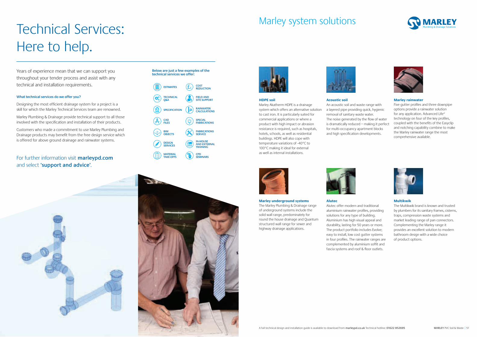
5150 MARLEY PVC Soil & Waste || MARLEY PVC Soil & Waste
Marley system solutions
HDPE soil Marley Akatherm HDPE is a drainage system which offers an alternative solution to cast iron. It is particularly suited for commercial applications or where a product with high impact or abrasion resistance is required, such as hospitals, hotels, schools, as well as residential buildings. HDPE will also cope with temperature variations of -40°C to 100°C making it ideal for external as well as internal installations.
Acoustic soil An acoustic soil and waste range with a layered pipe providing quick, hygienic removal of sanitary waste water. The noise generated by the flow of water is dramatically reduced – making it perfect for multi-occupancy apartment blocks and high specification developments.
Marley rainwater Five gutter profiles and three downpipe options provide a rainwater solution for any application. Advanced Life4 technology on four of the key profiles, coupled with the benefits of the Easyclip and notching capability combine to make the Marley rainwater range the most comprehensive available.
Marley underground systems The Marley Plumbing & Drainage range of underground systems include the solid wall range, predominately for round the house drainage and Quantum structured wall range for sewer and highway drainage applications.
Alutec Alutec offer modern and traditional aluminium rainwater profiles, providing solutions for any type of building. Aluminium has high visual appeal and durability, lasting for 50 years or more. The product portfolio includes Evolve; easy to install, low cost gutter systems in four profiles. The rainwater ranges are complemented by aluminium soffit and fascia systems and roof & floor outlets.
Multikwik The Multikwik brand is known and trusted by plumbers for its sanitary frames, cisterns, traps, compression waste systems and market leading range of pan connectors. Complementing the Marley range it provides an excellent solution to modern bathroom design with a wide choice of product options.
A full technical design and installation guide is available to download from marleypd.co.uk Technical hotline: 01622 852695
ESTIMATES ££COSTREDUCTION
TECHNICAL Q&A
FIELD AND SITE SUPPORT
SPECIFICATION RAINWATER CALCULATIONS
CADFILES
SPECIALFABRICATIONS
BIMOBJECTS
FABRICATIONS SERVICE
DESIGNSERVICES
IN-HOUSEAND EXTERNAL TRAINING
MATERIALTAKE-OFFS
CPDSEMINARS
Below are just a few examples of the technical services we offer:
Years of experience mean that we can support you
throughout your tender process and assist with any
technical and installation requirements.
What technical services do we offer you?
Designing the most effi cient drainage system for a project is a skill for which the Marley Technical Services team are renowned.
Marley Plumbing & Drainage provide technical support to all those involved with the specifi cation and installation of their products.
Customers who made a commitment to use Marley Plumbing and Drainage products may benefi t from the free design service which is offered for above ground drainage and rainwater systems.
For further information visit marleypd.com and select ‘support and advice’.
Technical Services:Here to help.

marleypd.co.uk For general enquiries and details of your nearest stockist please call the customer services department: Tel: 01622 852585Email: [email protected]
To place an order
For delivery to England & WalesEmail: [email protected]: 01622 851111For delivery to ScotlandEmail: [email protected]: 01698 810307
For all estimate requestsEmail: [email protected]
For Technical advice please call 01622 852695
Head OfficeLenham, Maidstone Kent ME17 2DE Tel: 01622 858888 Fax: 01622 858725
ScotlandBirkenshaw Industrial Estate Uddingston, Glasgow G71 5PA Tel: 01698 815231 Fax: 01698 810307
Export DivisionLenham, Maidstone Kent ME17 2DE England Tel: +44 (0)1622 858888 Fax: +44 (0)1622 850778
May 2016