Embed Size (px)
Citation preview
PVC Conduit & Fittings Versatile applications from housing to heavy industry
CM
E /
PV
C C
ondu
it &
Fitt
ings
/ G
CC
07/
10

PVC conduit & fittings 3
PVC CONDUIT & FITTINGS
Contents
Corrugated Conduit.................................... 5
Rigid PVC Conduit...................................... 5
20mm Junction Boxes................................ 5
25mm Junction Boxes................................ 6
20mm Deep Junction Boxes....................... 6
25mm Deep Junction Boxes....................... 7
Junction Box Lids....................................... 7
Female Adaptors......................................... 7
Plain Couplings........................................... 8
Expansion Couplings.................................. 8
Bends.......................................................... 8
Conduit Mounting Accessories................... 8
Adaptable Boxes......................................... 9
Bending Springs.......................................... 9
PVC Jointing Cement.................................. 9
PVC conduit & fittings4
PRODUCT FEATURES
PVC CONDUIT & FITTINGS
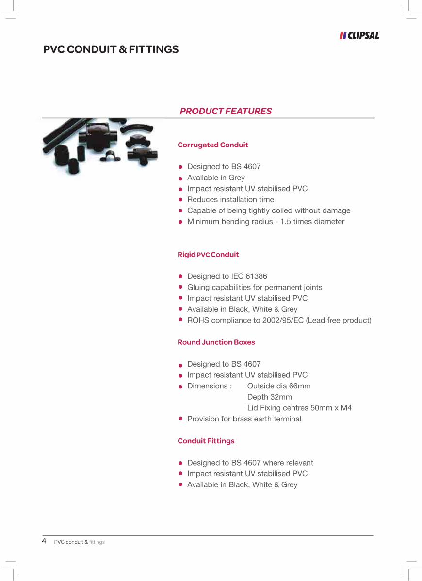
Corrugated Conduit
Designed to BS 4607 Available in Grey Impact resistant UV stabilised PVC Reduces installation time Capable of being tightly coiled without damage Minimum bending radius - 1.5 times diameter
Rigid Pvc Conduit Designed to IEC 61386 Gluing capabilities for permanent joints Impact resistant UV stabilised PVC Available in Black, White & Grey ROHS compliance to 2002/95/EC (Lead free product)
Round Junction Boxes Designed to BS 4607 Impact resistant UV stabilised PVC Dimensions : Outside dia 66mm Depth 32mm Lid Fixing centres 50mm x M4 Provision for brass earth terminal
Conduit Fittings
Designed to BS 4607 where relevant Impact resistant UV stabilised PVC Available in Black, White & Grey
PVC conduit & fittings 5
PVC CONDUIT & FITTINGS
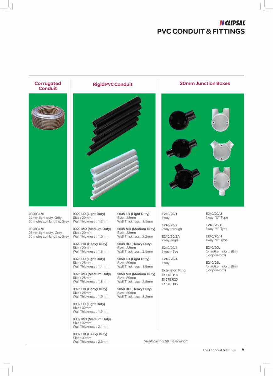
Corrugated Conduit
Rigid Pvc Conduit 20mm Junction Boxes
9020CLM20mm light duty, Grey50 metre coil lengths, Grey
9025CLM25mm light duty, Grey50 metre coil lengths, Grey
9020 LD (Light Duty)Size : 20mmWall Thickness : 1.2mm
9020 MD (Medium Duty)Size : 20mmWall Thickness : 1.6mm
9020 HD (Heavy Duty)Size : 20mmWall Thickness : 1.8mm
9025 LD (Light Duty)Size : 25mmWall Thickness : 1.4mm
9025 MD (Medium Duty)Size : 25mmWall Thickness : 1.8mm
9025 HD (Heavy Duty)Size : 25mmWall Thickness : 1.9mm
9032 LD (Light Duty)Size : 32mmWall Thickness : 1.5mm
9032 MD (Medium Duty)Size : 32mmWall Thickness : 2.1mm
9032 HD (Heavy Duty)Size : 32mmWall Thickness : 2.5mm
9038 LD (Light Duty)Size : 38mmWall Thickness : 1.5mm
9038 MD (Medium Duty)Size : 38mmWall Thickness : 2.2mm
9038 HD (Heavy Duty)Size : 38mmWall Thickness : 2.5mm
9050 LD (Light Duty)Size : 50mmWall Thickness : 1.9mm
9050 MD (Medium Duty)Size : 50mmWall Thickness : 2.5mm
9050 HD (Heavy Duty)Size : 50mmWall Thickness : 3.2mm
E240/20/11way
E240/20/22way through
E240/20/2A2way angle
E240/20/33way - Tee
E240/20/44way
Extension RingE157ER16E157ER25E157ER35
E240/20/U2way “U” Type
E240/20/Y3way “Y” Type
E240/20/H4way “H” Type
E240/20L4 b ack kno cko ut s 20mm (Loop-in-box)
E240/25L4 b ack kno cko ut s 25mm (Loop-in-box)
*Available in 2.90 meter length
PVC conduit & fittings4
PRODUCT FEATURES
PVC CONDUIT & FITTINGS
Corrugated Conduit
Designed to BS 4607 Available in Grey Impact resistant UV stabilised PVC Reduces installation time Capable of being tightly coiled without damage Minimum bending radius - 1.5 times diameter
Rigid Pvc Conduit Designed to IEC 61386 Gluing capabilities for permanent joints Impact resistant UV stabilised PVC Available in Black, White & Grey ROHS compliance to 2002/95/EC (Lead free product)
Round Junction Boxes Designed to BS 4607 Impact resistant UV stabilised PVC Dimensions : Outside dia 66mm Depth 32mm Lid Fixing centres 50mm x M4 Provision for brass earth terminal
Conduit Fittings
Designed to BS 4607 where relevant Impact resistant UV stabilised PVC Available in Black, White & Grey
PVC conduit & fittings 5
PVC CONDUIT & FITTINGS
Corrugated Conduit
Rigid Pvc Conduit 20mm Junction Boxes
9020CLM20mm light duty, Grey50 metre coil lengths, Grey
9025CLM25mm light duty, Grey50 metre coil lengths, Grey
9020 LD (Light Duty)Size : 20mmWall Thickness : 1.2mm
9020 MD (Medium Duty)Size : 20mmWall Thickness : 1.6mm
9020 HD (Heavy Duty)Size : 20mmWall Thickness : 1.8mm
9025 LD (Light Duty)Size : 25mmWall Thickness : 1.4mm
9025 MD (Medium Duty)Size : 25mmWall Thickness : 1.8mm
9025 HD (Heavy Duty)Size : 25mmWall Thickness : 1.9mm
9032 LD (Light Duty)Size : 32mmWall Thickness : 1.5mm
9032 MD (Medium Duty)Size : 32mmWall Thickness : 2.1mm
9032 HD (Heavy Duty)Size : 32mmWall Thickness : 2.5mm
9038 LD (Light Duty)Size : 38mmWall Thickness : 1.5mm
9038 MD (Medium Duty)Size : 38mmWall Thickness : 2.2mm
9038 HD (Heavy Duty)Size : 38mmWall Thickness : 2.5mm
9050 LD (Light Duty)Size : 50mmWall Thickness : 1.9mm
9050 MD (Medium Duty)Size : 50mmWall Thickness : 2.5mm
9050 HD (Heavy Duty)Size : 50mmWall Thickness : 3.2mm
E240/20/11way
E240/20/22way through
E240/20/2A2way angle
E240/20/33way - Tee
E240/20/44way
Extension RingE157ER16E157ER25E157ER35
E240/20/U2way “U” Type
E240/20/Y3way “Y” Type
E240/20/H4way “H” Type
E240/20L4 b ack kno cko ut s 20mm (Loop-in-box)
E240/25L4 b ack kno cko ut s 25mm (Loop-in-box)
*Available in 2.90 meter length
PVC conduit & fittings6
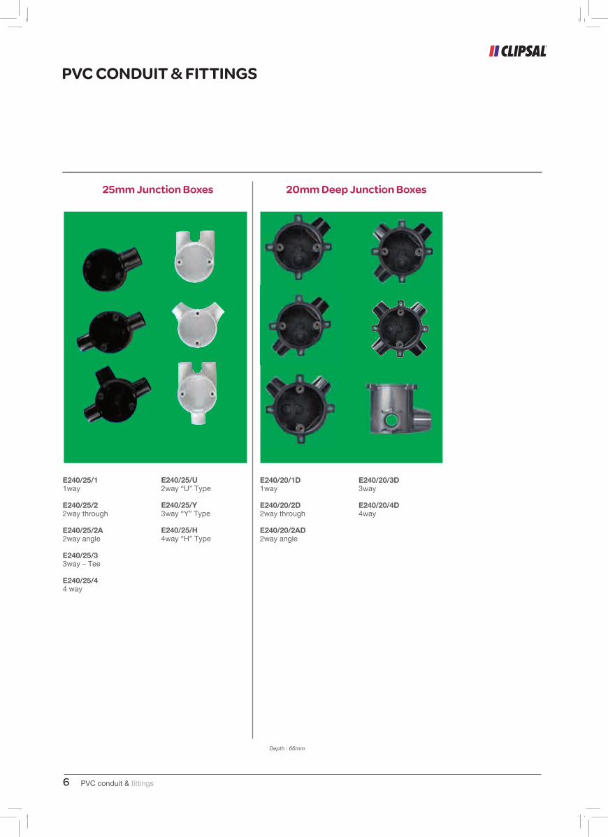
Depth : 66mm
PVC CONDUIT & FITTINGS
25mm Junction Boxes 20mm Deep Junction Boxes
E240/25/11way
E240/25/22way through
E240/25/2A2way angle
E240/25/33way – Tee
E240/25/44 way
E240/25/U2way “U” Type
E240/25/Y3way “Y” Type
E240/25/H4way “H” Type
E240/20/1D1way
E240/20/2D2way through
E240/20/2AD2way angle
E240/20/3D3way
E240/20/4D4way
PVC conduit & fittings 7
PVC CONDUIT & FITTINGS
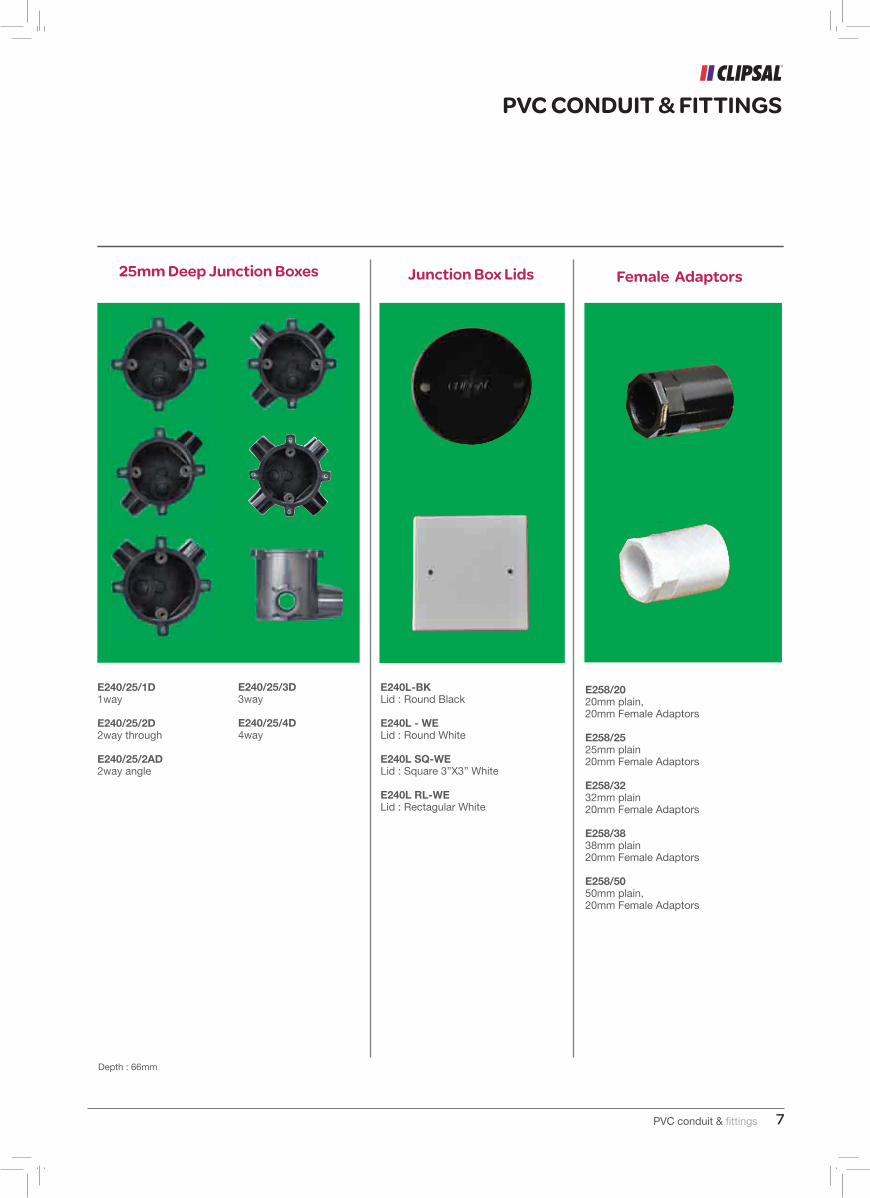
25mm Deep Junction Boxes Junction Box Lids Female Adaptors
Depth : 66mm
E240/25/1D1way
E240/25/2D2way through
E240/25/2AD2way angle
E240/25/3D3way
E240/25/4D4way
E240L-BKLid : Round Black
E240L - WELid : Round White
E240L SQ-WELid : Square 3”X3” White
E240L RL-WELid : Rectagular White
E258/2020mm plain,20mm Female Adaptors
E258/2525mm plain20mm Female Adaptors
E258/3232mm plain20mm Female Adaptors
E258/3838mm plain20mm Female Adaptors
E258/5050mm plain,20mm Female Adaptors
PVC conduit & fittings6
Depth : 66mm
PVC CONDUIT & FITTINGS
25mm Junction Boxes 20mm Deep Junction Boxes
E240/25/11way
E240/25/22way through
E240/25/2A2way angle
E240/25/33way – Tee
E240/25/44 way
E240/25/U2way “U” Type
E240/25/Y3way “Y” Type
E240/25/H4way “H” Type
E240/20/1D1way
E240/20/2D2way through
E240/20/2AD2way angle
E240/20/3D3way
E240/20/4D4way
PVC conduit & fittings 7
PVC CONDUIT & FITTINGS
25mm Deep Junction Boxes Junction Box Lids Female Adaptors
Depth : 66mm
E240/25/1D1way
E240/25/2D2way through
E240/25/2AD2way angle
E240/25/3D3way
E240/25/4D4way
E240L-BKLid : Round Black
E240L - WELid : Round White
E240L SQ-WELid : Square 3”X3” White
E240L RL-WELid : Rectagular White
E258/2020mm plain,20mm Female Adaptors
E258/2525mm plain20mm Female Adaptors
E258/3232mm plain20mm Female Adaptors
E258/3838mm plain20mm Female Adaptors
E258/5050mm plain,20mm Female Adaptors
PVC conduit & fittings8
PVC CONDUIT & FITTINGS
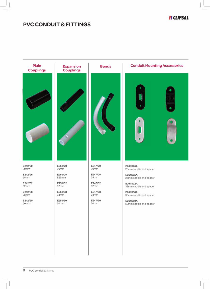
Plain Couplings
E242/2020mm
E242/2525mm
E242/3232mm
E242/3838mm
E242/5050mm
Expansion Couplings
Bends Conduit Mounting Accessories
E251/2020mm
E251/25E25mm
E251/3232mm
E251/3838mm
E251/5050mm
E247/2020mm
E247/2525mm
E247/3232mm
E247/3838mm
E247/5050mm
E261S20A20mm saddle and spacer
E261S25A25mm saddle and spacer
E261S32A32mm saddle and spacer
E261S38A38mm saddle and spacer
E261S50A50mm saddle and spacer
PVC conduit & fittings 9
Designed to BS 4607
PVC CONDUIT & FITTINGS
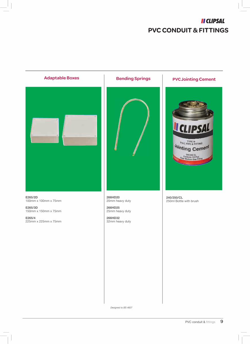
Adaptable Boxes Bending Springs Pvc Jointing Cement
E265/2D100mm x 100mm x 75mm
E265/3D150mm x 150mm x 75mm
E265/4225mm x 225mm x 75mm
266HD2020mm heavy duty
266HD2525mm heavy duty
266HD3232mm heavy duty
240/250/CL250ml Bottle with brush
PVC conduit & fittings8
PVC CONDUIT & FITTINGS
Plain Couplings
E242/2020mm
E242/2525mm
E242/3232mm
E242/3838mm
E242/5050mm
Expansion Couplings
Bends Conduit Mounting Accessories
E251/2020mm
E251/25E25mm
E251/3232mm
E251/3838mm
E251/5050mm
E247/2020mm
E247/2525mm
E247/3232mm
E247/3838mm
E247/5050mm
E261S20A20mm saddle and spacer
E261S25A25mm saddle and spacer
E261S32A32mm saddle and spacer
E261S38A38mm saddle and spacer
E261S50A50mm saddle and spacer
PVC conduit & fittings 9
Designed to BS 4607
PVC CONDUIT & FITTINGS
Adaptable Boxes Bending Springs Pvc Jointing Cement
E265/2D100mm x 100mm x 75mm
E265/3D150mm x 150mm x 75mm
E265/4225mm x 225mm x 75mm
266HD2020mm heavy duty
266HD2525mm heavy duty
266HD3232mm heavy duty
240/250/CL250ml Bottle with brush
PVC conduit & fittings10 1
Rigid PVC Conduits
PVC Conduit, Fittings & Accessories
PVC CONDUIT & FITTINGS
PVC conduit & fittings 11
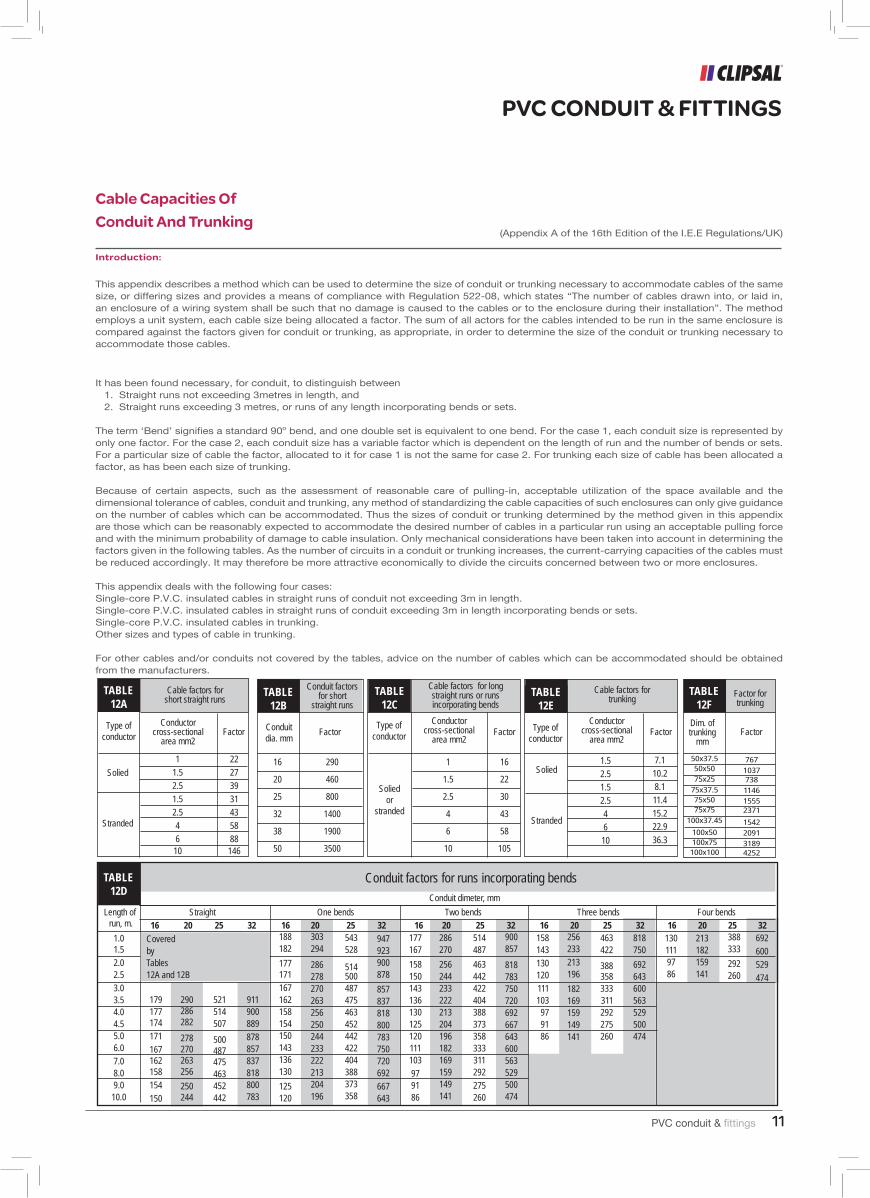
Cable Capacities Of Conduit And Trunking
PVC CONDUIT & FITTINGS
(Appendix A of the 16th Edition of the I.E.E Regulations/UK)
Introduction:
This appendix describes a method which can be used to determine the size of conduit or trunking necessary to accommodate cables of the same size, or differing sizes and provides a means of compliance with Regulation 522-08, which states “The number of cables drawn into, or laid in, an enclosure of a wiring system shall be such that no damage is caused to the cables or to the enclosure during their installation”. The method employs a unit system, each cable size being allocated a factor. The sum of all actors for the cables intended to be run in the same enclosure is compared against the factors given for conduit or trunking, as appropriate, in order to determine the size of the conduit or trunking necessary to accommodate those cables.
It has been found necessary, for conduit, to distinguish between 1. Straight runs not exceeding 3metres in length, and 2. Straight runs exceeding 3 metres, or runs of any length incorporating bends or sets.
The term ‘Bend’ signifies a standard 90o bend, and one double set is equivalent to one bend. For the case 1, each conduit size is represented by only one factor. For the case 2, each conduit size has a variable factor which is dependent on the length of run and the number of bends or sets. For a particular size of cable the factor, allocated to it for case 1 is not the same for case 2. For trunking each size of cable has been allocated a factor, as has been each size of trunking.
Because of certain aspects, such as the assessment of reasonable care of pulling-in, acceptable utilization of the space available and the dimensional tolerance of cables, conduit and trunking, any method of standardizing the cable capacities of such enclosures can only give guidance on the number of cables which can be accommodated. Thus the sizes of conduit or trunking determined by the method given in this appendix are those which can be reasonably expected to accommodate the desired number of cables in a particular run using an acceptable pulling force and with the minimum probability of damage to cable insulation. Only mechanical considerations have been taken into account in determining the factors given in the following tables. As the number of circuits in a conduit or trunking increases, the current-carrying capacities of the cables must be reduced accordingly. It may therefore be more attractive economically to divide the circuits concerned between two or more enclosures.
This appendix deals with the following four cases:Single-core P.V.C. insulated cables in straight runs of conduit not exceeding 3m in length.Single-core P.V.C. insulated cables in straight runs of conduit exceeding 3m in length incorporating bends or sets.Single-core P.V.C. insulated cables in trunking.Other sizes and types of cable in trunking.
For other cables and/or conduits not covered by the tables, advice on the number of cables which can be accommodated should be obtained from the manufacturers.
TABLE12A
Type ofconductor
Conductorcross-sectional
area mm2Factor
Cable factors for short straight runs
TABLE12B
Solied
1
1.5
2.5
1.5
2.5
4
610
22
27
39
31
43
58
88146
Stranded
Conduitdia. mm
Factor
16
20
25
32
38
50
Conduit factors for short
straight runs
290
460
800
1400
1900
3500
Type ofconductor
TABLE12C
Soliedor
stranded
1
1.5
2.5
4
6
10
Conductorcross-sectional
area mm2Factor
16
22
30
43
58
105
Cable factors for long straight runs or runs incorporating bends
TABLE12E
Type ofconductor
Cable factors for trunking
Conductorcross-sectional
area mm2Factor
TABLE12F
Dim. of trunking
mmFactor
Factor fortrunking
Solied
Stranded
1.5
2.5
1.5
2.5
4
6
10
7.1
10.2
8.1
11.4
15.2
22.9
36.3
50x37.550x50
75x25
75x37.575x5075x75
100x37.45
100x50100x75100x100
767
1037738
1146
15552371
1542
2091
31894252
1.01.5
2.02.5
3.03.54.04.55.06.0
7.08.09.0
10.0
179177174
171
167162158
154
150
290286282
278270263256
250244
521514507
500487475463452442
911900889
878857837818800783
188182
177171
167162158154150143136130
125120
303294
286278270263256250244233222213204196
543528
514500487475463452442422404388373358
947923900878
857837818800783750720692
667643
177167
158150143136130125120111103
979186
286270
256244233222213204196182169159149141
514487
463442422404388373358333311292
275260
900857
818783750720692667643600563529500474
158143
130120
111103
979186
256233
213196
182169159149141
463422
388358333311292275260
818750
692643600563529500474
1301119786
213182159141
388333
292260
692
600
529
474
16 20 25 32 16 20 25 32 16 20 25 32 16 20 25 32 16 20 25 32Straight One bends Two bends Three bends Four bends
TABLE12D
Length of run, m.
Conduit factors for runs incorporating bendsConduit dimeter, mm
Covered by Tables12A and 12B
1
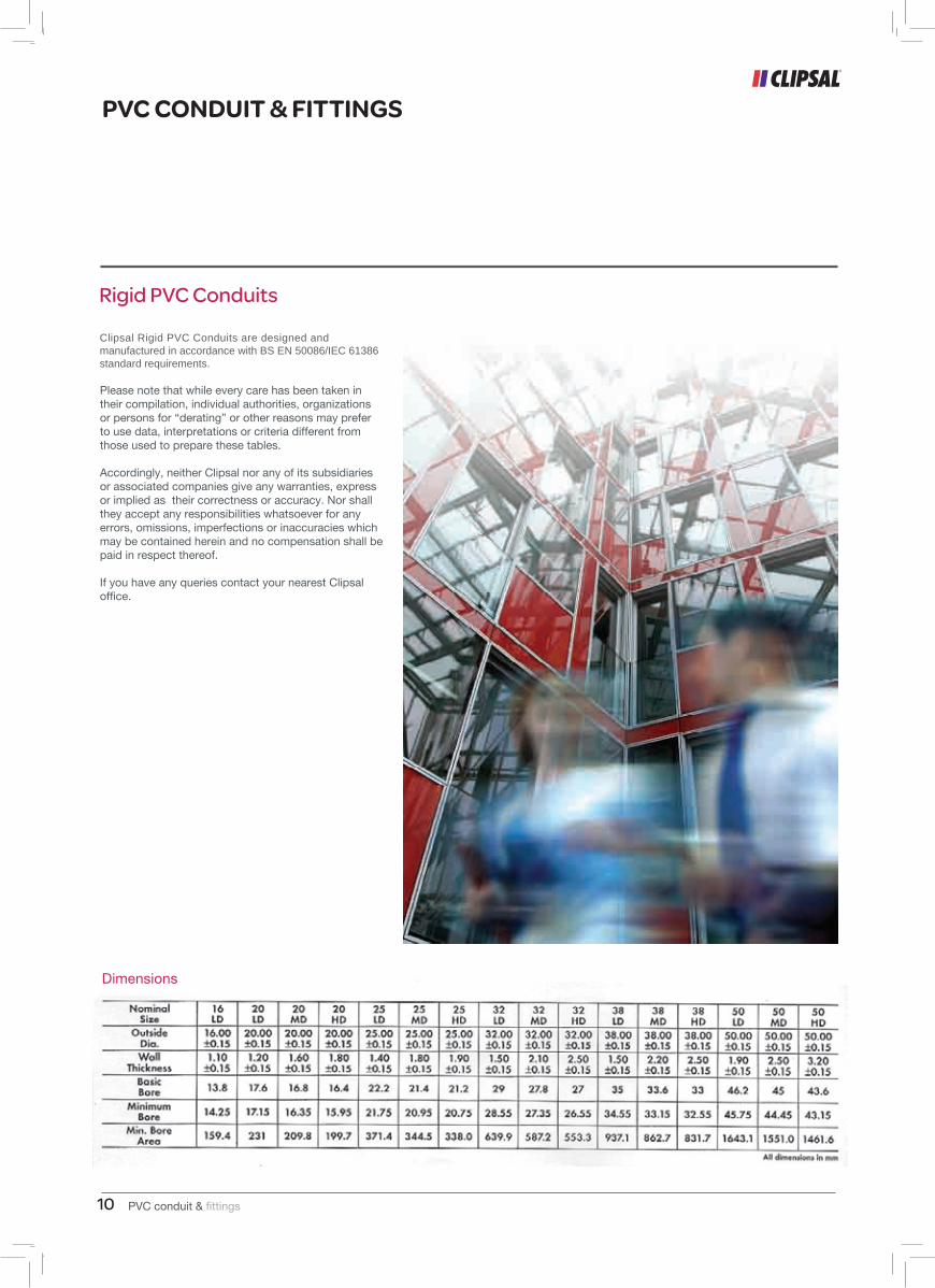
Rigid PVC Conduits
PVC Conduit, Fittings & Accessories
Clipsal Rigid PVC Conduits are designed and manufactured in accordance with BS EN 50086/IEC 61386 standard requirements.
PVC conduit & fittings10 1
Rigid PVC Conduits
PVC Conduit, Fittings & Accessories
PVC CONDUIT & FITTINGS
PVC conduit & fittings 11
Cable Capacities Of Conduit And Trunking
PVC CONDUIT & FITTINGS
(Appendix A of the 16th Edition of the I.E.E Regulations/UK)
Introduction:
This appendix describes a method which can be used to determine the size of conduit or trunking necessary to accommodate cables of the same size, or differing sizes and provides a means of compliance with Regulation 522-08, which states “The number of cables drawn into, or laid in, an enclosure of a wiring system shall be such that no damage is caused to the cables or to the enclosure during their installation”. The method employs a unit system, each cable size being allocated a factor. The sum of all actors for the cables intended to be run in the same enclosure is compared against the factors given for conduit or trunking, as appropriate, in order to determine the size of the conduit or trunking necessary to accommodate those cables.
It has been found necessary, for conduit, to distinguish between 1. Straight runs not exceeding 3metres in length, and 2. Straight runs exceeding 3 metres, or runs of any length incorporating bends or sets.
The term ‘Bend’ signifies a standard 90o bend, and one double set is equivalent to one bend. For the case 1, each conduit size is represented by only one factor. For the case 2, each conduit size has a variable factor which is dependent on the length of run and the number of bends or sets. For a particular size of cable the factor, allocated to it for case 1 is not the same for case 2. For trunking each size of cable has been allocated a factor, as has been each size of trunking.
Because of certain aspects, such as the assessment of reasonable care of pulling-in, acceptable utilization of the space available and the dimensional tolerance of cables, conduit and trunking, any method of standardizing the cable capacities of such enclosures can only give guidance on the number of cables which can be accommodated. Thus the sizes of conduit or trunking determined by the method given in this appendix are those which can be reasonably expected to accommodate the desired number of cables in a particular run using an acceptable pulling force and with the minimum probability of damage to cable insulation. Only mechanical considerations have been taken into account in determining the factors given in the following tables. As the number of circuits in a conduit or trunking increases, the current-carrying capacities of the cables must be reduced accordingly. It may therefore be more attractive economically to divide the circuits concerned between two or more enclosures.
This appendix deals with the following four cases:Single-core P.V.C. insulated cables in straight runs of conduit not exceeding 3m in length.Single-core P.V.C. insulated cables in straight runs of conduit exceeding 3m in length incorporating bends or sets.Single-core P.V.C. insulated cables in trunking.Other sizes and types of cable in trunking.
For other cables and/or conduits not covered by the tables, advice on the number of cables which can be accommodated should be obtained from the manufacturers.
TABLE12A
Type ofconductor
Conductorcross-sectional
area mm2Factor
Cable factors for short straight runs
TABLE12B
Solied
1
1.5
2.5
1.5
2.5
4
610
22
27
39
31
43
58
88146
Stranded
Conduitdia. mm
Factor
16
20
25
32
38
50
Conduit factors for short
straight runs
290
460
800
1400
1900
3500
Type ofconductor
TABLE12C
Soliedor
stranded
1
1.5
2.5
4
6
10
Conductorcross-sectional
area mm2Factor
16
22
30
43
58
105
Cable factors for long straight runs or runs incorporating bends
TABLE12E
Type ofconductor
Cable factors for trunking
Conductorcross-sectional
area mm2Factor
TABLE12F
Dim. of trunking
mmFactor
Factor fortrunking
Solied
Stranded
1.5
2.5
1.5
2.5
4
6
10
7.1
10.2
8.1
11.4
15.2
22.9
36.3
50x37.550x50
75x25
75x37.575x5075x75
100x37.45
100x50100x75
100x100
767
1037738
1146
15552371
1542
2091
31894252
1.01.5
2.02.5
3.03.54.04.55.06.0
7.08.09.0
10.0
179177174
171
167162158
154
150
290286282
278270263256
250244
521514507
500487475463452442
911900889
878857837818800783
188182
177171
167162158154150143136130
125120
303294
286278270263256250244233222213204196
543528
514500487475463452442422404388373358
947923900878
857837818800783750720692
667643
177167
158150143136130125120111103
979186
286270
256244233222213204196182169159149141
514487
463442422404388373358333311292
275260
900857
818783750720692667643600563529500474
158143
130120
111103979186
256233
213196
182169159149141
463422
388358333311292275260
818750
692643600563529500474
1301119786
213182159141
388333
292260
692
600
529
474
16 20 25 32 16 20 25 32 16 20 25 32 16 20 25 32 16 20 25 32Straight One bends Two bends Three bends Four bends
TABLE12D
Length of run, m.
Conduit factors for runs incorporating bendsConduit dimeter, mm
Covered by Tables12A and 12B
1
Rigid PVC Conduits
PVC Conduit, Fittings & Accessories
PVC conduit & fittings12
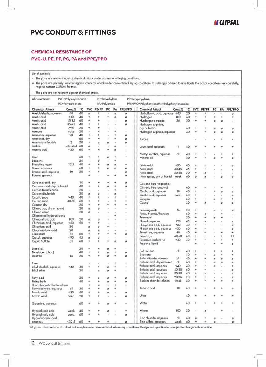
CHEMICAL RESISTANCE OF PVC-U, PE, PP, PC, PA and PPE/PPO
PVC CONDUIT & FITTINGS
PVC conduit & fittings 13
CHEMICAL RESISTANCE OF PVC-U
The resistance against chemical attack basically on the mechanical stress of the plastic part, the time of exposure, the temperature and the concentration of the media. In view of the various environmental conditions laboratory tests under standard conditions are only of limited value for practical use. Under critical conditions tests should be made according to actual conditions to be stated by the user.
Mechanical stress and temperature
Mechanical stress can be minimized at the installation, taking care that the system is being installed as stressfree as possible, e.g. using large bending radii, leaving space for thermal expansion at the joints and taking care, that fixings are not fastened too firmly. Using insulating systems at higher temperatures, the thermal expansion must be taken into account to avoid later stresses on the installed system by using expansion joints and allow gliding within the fixings. At higher temperatures it must be taken into consideration that especially in sealed closed systems, temperatures may occur exceeding the surrounding temperatures. This can be due to additional heat through the cables or heat radiation (sunlight), the following survey gives general information about possible incompatibilities occurring during installation or use.
Chemical resistance of PVC Systems
PVC offers excellent resistance against most chemicals used in the building industry. Care shall be taken with chemicals like carbon tetrachloride acetone, chlorinated hydrocarbons and benzene.
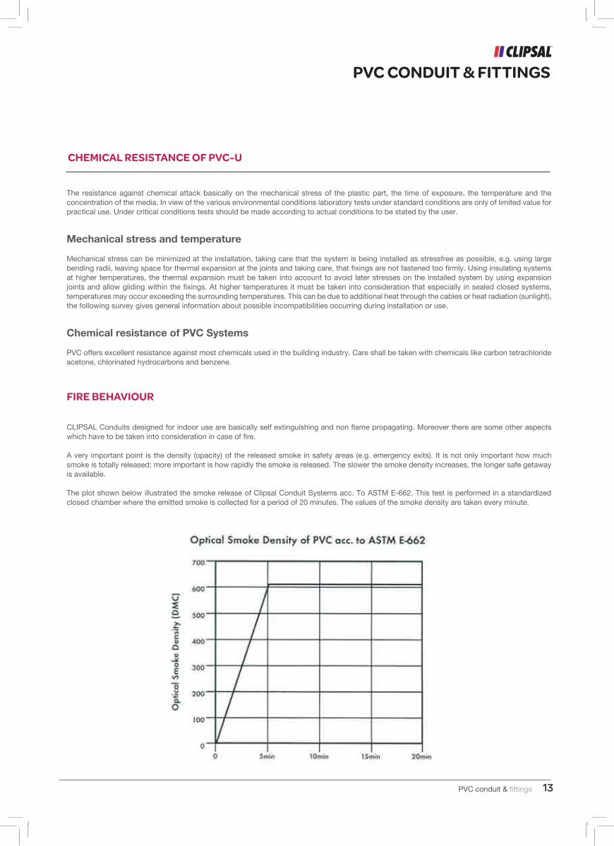
FIRE BEHAVIOUR
CLIPSAL Conduits designed for indoor use are basically self extinguishing and non flame propagating. Moreover there are some other aspects which have to be taken into consideration in case of fire.
A very important point is the density (opacity) of the released smoke in safety areas (e.g. emergency exits). It is not only important how much smoke is totally released; more important is how rapidly the smoke is released. The slower the smoke density increases, the longer safe getaway is available.
The plot shown below illustrated the smoke release of Clipsal Conduit Systems acc. To ASTM E-662. This test is performed in a standardized closed chamber where the emitted smoke is collected for a period of 20 minutes. The values of the smoke density are taken every minute.
PVC CONDUIT & FITTINGS
PVC conduit & fittings12
CHEMICAL RESISTANCE OF PVC-U, PE, PP, PC, PA and PPE/PPO
PVC CONDUIT & FITTINGS
PVC conduit & fittings 13
CHEMICAL RESISTANCE OF PVC-U
The resistance against chemical attack basically on the mechanical stress of the plastic part, the time of exposure, the temperature and the concentration of the media. In view of the various environmental conditions laboratory tests under standard conditions are only of limited value for practical use. Under critical conditions tests should be made according to actual conditions to be stated by the user.
Mechanical stress and temperature
Mechanical stress can be minimized at the installation, taking care that the system is being installed as stressfree as possible, e.g. using large bending radii, leaving space for thermal expansion at the joints and taking care, that fixings are not fastened too firmly. Using insulating systems at higher temperatures, the thermal expansion must be taken into account to avoid later stresses on the installed system by using expansion joints and allow gliding within the fixings. At higher temperatures it must be taken into consideration that especially in sealed closed systems, temperatures may occur exceeding the surrounding temperatures. This can be due to additional heat through the cables or heat radiation (sunlight), the following survey gives general information about possible incompatibilities occurring during installation or use.
Chemical resistance of PVC Systems
PVC offers excellent resistance against most chemicals used in the building industry. Care shall be taken with chemicals like carbon tetrachloride acetone, chlorinated hydrocarbons and benzene.
FIRE BEHAVIOUR
CLIPSAL Conduits designed for indoor use are basically self extinguishing and non flame propagating. Moreover there are some other aspects which have to be taken into consideration in case of fire.
A very important point is the density (opacity) of the released smoke in safety areas (e.g. emergency exits). It is not only important how much smoke is totally released; more important is how rapidly the smoke is released. The slower the smoke density increases, the longer safe getaway is available.
The plot shown below illustrated the smoke release of Clipsal Conduit Systems acc. To ASTM E-662. This test is performed in a standardized closed chamber where the emitted smoke is collected for a period of 20 minutes. The values of the smoke density are taken every minute.
PVC CONDUIT & FITTINGS
PVC conduit & fittings14
Notes

PVC conduit & fittings14
Notes

www.clipsal.ae
FactoryPO. Box: 8080Saif Zone, Sharjah-UAEPh: +971 6 5570555, Fax: +971 6 5570707